Airspan Networks ASMAX698 WiMAX Outdoor CPE User Manual AirStream 4000
Airspan Networks Inc WiMAX Outdoor CPE AirStream 4000
UserManual.wiki
>
Airspan Networks
>
ASMAX698 User Manual
User manual rev2
Navigation menu
Upload a User Manual
Namespaces
Wiki Guide
HTML
PDF
Info
Views
User Manual
Discussion / Help
Navigation

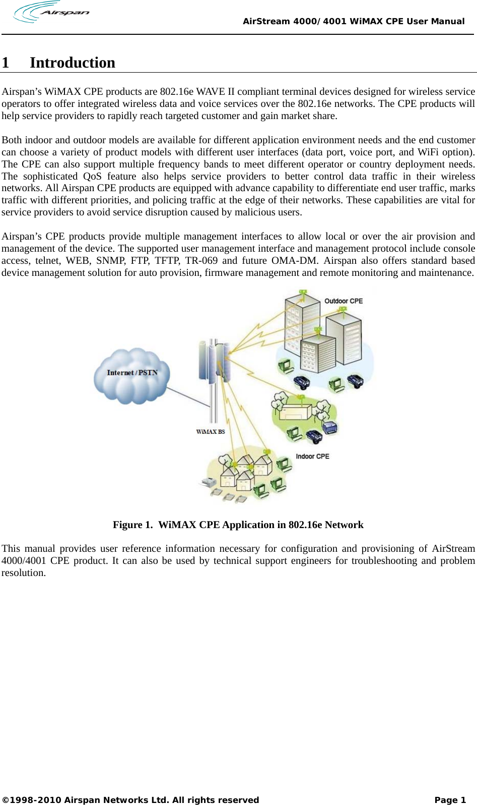
![AirStream 4000/4001 WiMAX CPE User Manual ©1998-2010 Airspan Networks Ltd. All rights reserved Page 10 The lower right frame of the web page has three buttons: Effective configuration data are stored in RAM (Random Access Memory). Once the CPE is powered off, all effective configurations in RAM will be lost unless they are saved into non-volatile flash memory. Information Users are advised to save configuration changes, after Applying changes in the Detailed Configuration Window. Device configuration in RAM can be saved, by clicking on [Save Data] button, into non-volatile flash memory, which can be reloaded automatically every time when CPE boots up. Device configuration can be restored to factory default by clicking on [Clear Data]. Resetting system will shutdown all processes and reboots the CPE device. The system software will be reloaded. The system software will read configuration data saved in non-volatile flash memory during the boot process.](https://usermanual.wiki/Airspan-Networks/ASMAX698/User-Guide-1448748-Page-15.png)
![AirStream 4000/4001 WiMAX CPE User Manual ©1998-2010 Airspan Networks Ltd. All rights reserved Page 46 4. Select the file “iad.prg”, click the “Open” button. 5. Click the [Load] button. 6. Reset system after loading finished. 11.2.1.2 Save system configurations from CPE The steps of backup configuration files via HTTP are as follows: 1. Choose the type of backup file as "Data" in the “File Type" column. 2. Click the “backup" button. 3. Click the “Save” button. 4. Select the file name and click the “Save” button. Information Many web browsers implemented security features which blocks downloading of a file. Check your browser settings to see if no File Save dialogue box appears. 11.2.2 Load or Backup over TFTP An external host running TFTP server can be used to backup the device configuration data, or restore configuration data to the IX253P device. Information The external host in this case serves as the TFTP server. The IAD serves as a TFTP client. 11.2.2.1 Load System Files from a TFTP Server](https://usermanual.wiki/Airspan-Networks/ASMAX698/User-Guide-1448748-Page-51.png)
![AirStream 4000/4001 WiMAX CPE User Manual ©1998-2010 Airspan Networks Ltd. All rights reserved Page 48 Parameters that are prone to cause operational failure are forbidden from access, e.g. change of dial number. Both admin and user has preferred language, and password setting. User name is the identifier of user, use admin or user to log on. Level is the privilege level of a certain user. Language defines default display language of web management pages for a user. Click on the “User Account” in Configuration Tree. The following will be shown in the detailed configuration window. The table on top of the page displays the user accounts that are already provisioned in the IX253P CPE. 11.4 System Time Click on “Date and Time” in the configuration tree in the left frame of browser window. The System Time will be displayed in the middle of the web page. 11.4.1 Date and Time Configuration The web page does not update the displayed time automatically. Click on [Refresh] button to view current system time.](https://usermanual.wiki/Airspan-Networks/ASMAX698/User-Guide-1448748-Page-53.png)
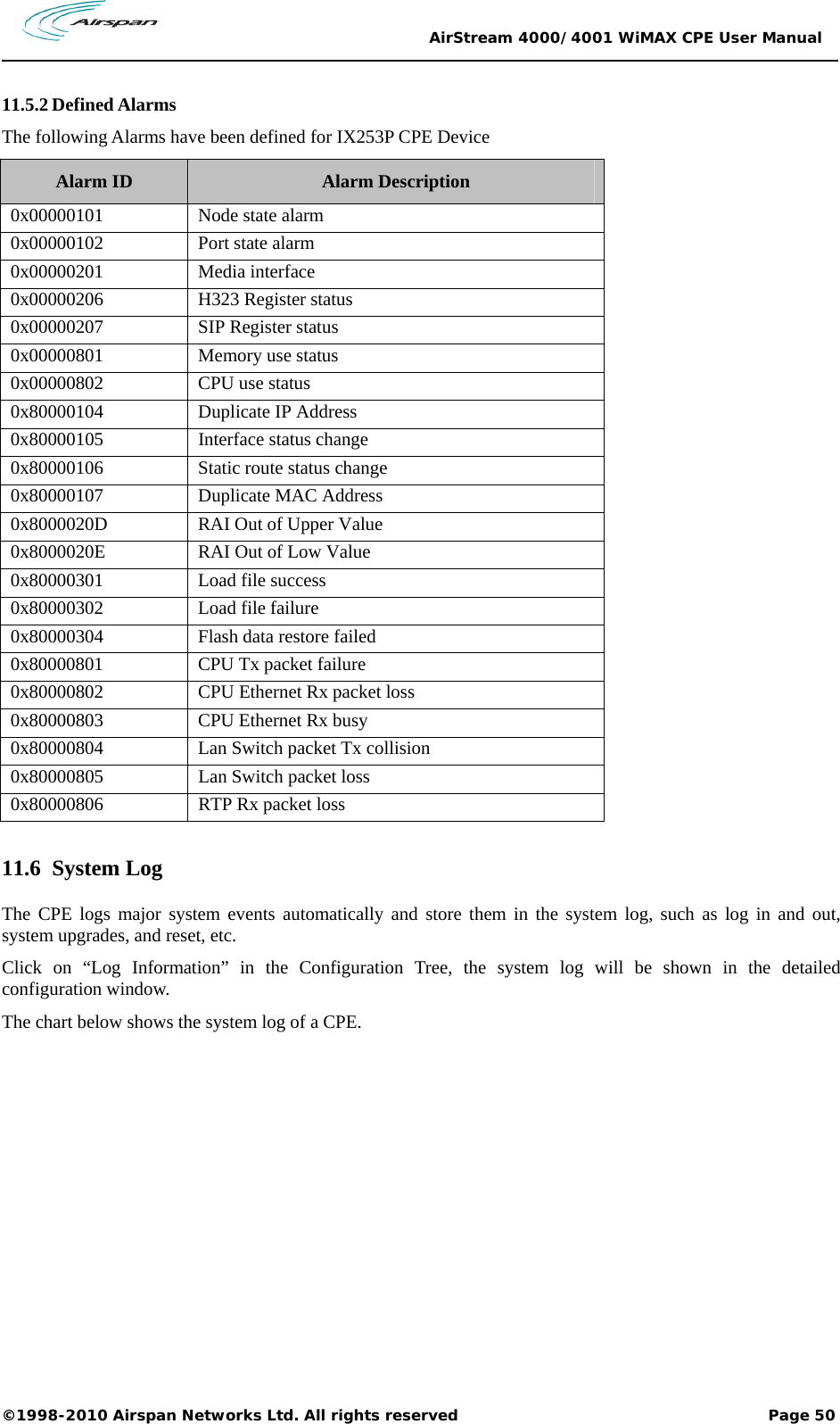
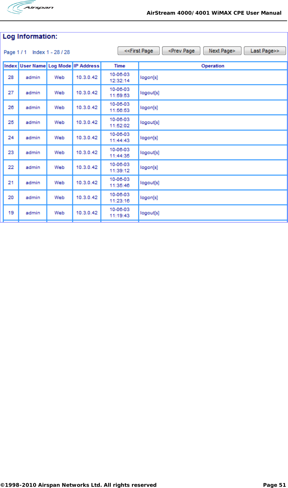
![AirStream 4000/4001 WiMAX CPE User Manual ©1998-2010 Airspan Networks Ltd. All rights reserved Page 49 To set system time, type in all the fields and click the [Apply] button. 11.4.2 NTP Server Configuration The CPE also supports the NTP (Network Timing Protocol) to synchronize its system time with a clock source with higher accuracy. 11.5 Alarms Information The CPE capture system faults and report them in the Alarms Information web management page. The Alarm information provides traces of fault and helps troubleshooting the device. 11.5.1 Current and History Alarm Click on “Alarm Information” in the Configuration Tree. All current and historical alarms will be displayed in the detailed configuration window.](https://usermanual.wiki/Airspan-Networks/ASMAX698/User-Guide-1448748-Page-54.png)