Airspan Networks AU545ENB25 LTE Mobile Digital Station User Manual AirUnity 545 eNB User Guide
Airspan Networks Inc LTE Mobile Digital Station AirUnity 545 eNB User Guide
Users Manual

AirUnity 545 eNB 2.5GHz (B41) User Guide
Part Number: UGD-D01127
System Release: 15.5
Revision: A
Published: February 2017

© Copyright by Airspan Networks Inc., 2016-2017. All rights reserved worldwide.
Legal Notices
The information contained within this document is proprietary, privileged and intended only for the
recipient. As such, the information is subject to all relevant copyright, patent and other laws protecting
intellectual property, as well as any specific agreements protecting Airspan Networks Ltd. rights in the
aforesaid information. Neither this document nor the information contained herein may be published,
reproduced, transmitted or disclosed to third parties, in whole or in part, without the express, prior,
written permission of Airspan Networks Ltd. In addition, any use of this document or the information
contained herein for the purposes other than those for which it is disclosed is strictly forbidden.
Airspan Networks Ltd. reserves the right, without prior notice or liability, to make changes in
equipment design or specifications.
Information supplied by Airspan Networks Ltd. is believed in good faith to be accurate and reliable,
while every care has been taken in preparing these documents. However, Airspan Networks Ltd. does
not make any representations and gives no warranties of whatever nature in respect of these
documents, including without limitation, the accuracy or completeness of any information, facts and/or
opinions contained therein. No responsibility is assumed by Airspan Networks Ltd. for the use of the
documents nor for the rights of third parties which may be effected in any way by the use thereof. The
provision of these documents (and the documents themselves) does not constitute professional
advice of any kind. Any representation(s) in these documents concerning performance of Airspan
Networks Ltd. product(s) are for informational purposes only and are not warranties of future
performance, either expressed or implied. Airspan Networks Ltd., its affiliates, directors, employees
and agents shall not be held liable for any damages or losses, of any nature whatsoever, arising from
any use of and/or reliance on the documents.
These documents may contain flaws, omissions or typesetting errors; no warranty is granted nor
liability assumed in relation thereto unless specifically undertaken in Airspan Networks Ltd. sales
contract or order confirmation. Information contained herein is periodically updated and changes will
be incorporated into subsequent editions. If you have encountered an error, please notify Airspan
Networks Ltd.
Product performance figures quoted within this document are indicative and for information purposes only.
UK WEEE Registration number: WEEE/AB0207WZ. For more information, see WEEE Information for Airspan
Customers and Recyclers.
Acknowledgements
© Intel Corporation http://www.intel.com/
© Microsoft Corporation http://www.microsoft.com

UGD-D01127 Airspan Commercial and Internal Use i
Table of Contents
Document Information ............................................................................. 2
Abstract .................................................................................................................. 2
Revision History ..................................................................................................... 2
Warnings and Cautions ........................................................................... 3
Human Exposure to Radio Frequencies ................................................................ 3
Radio Interference ................................................................................................. 3
Modifications .......................................................................................................... 3
General .................................................................................................................. 3
Important Safety Instructions ............................................................................ 3
Safety ..................................................................................................................... 3
Adherence to European Directive 1999/5/EC ........................................................ 5
Warning Symbols ................................................................................................... 5
Service Information ................................................................................................ 5
UL Information ....................................................................................................... 6
DECLARATION OF CONFORMITY....................................................................... 6
FCC Notice ............................................................................................................ 7
Federal Communication Commission Notice .......................................... 7
FCC Radiation Exposure Statement: ...................................................... 7
Maximum Output TX Total Power ........................................................... 8
Power Consumption ............................................................................................... 8
Antenna Usage ...................................................................................................... 9
Antenna Types ....................................................................................................... 9
About This Document ........................................................................... 10
Purpose ................................................................................................................ 10
Intended Audience ............................................................................................... 10
Document Conventions ........................................................................................ 10
Customer Care Help Desk .................................................................... 11
Airspan Encourages Comments .......................................................................... 11
1 Overview ........................................................................................... 12

AirUnity 545 eNB 2.5GHz (B41) User Guide
UGD-D01127 Airspan Commercial and Internal Use ii
1.1 Management ................................................................................................. 12
1.2 AirUnity 545 eNB Unit Frequency Ranges .................................................... 12
2 Physical Description .......................................................................... 13
2.1 AirUnity 545 eNB 2.5GHz (B41) .................................................................... 13
2.1.1 Physical Dimensions .................................................................................... 13
2.1.2 Digital Display (Touch Screen) ..................................................................... 14
2.1.3 SIM Card ...................................................................................................... 14
2.2 Synchronisation ............................................................................................. 14
2.2.1 Synchronisation Compliance ........................................................................ 14
2.2.2 Frequency Accuracy ..................................................................................... 14
2.2.3 Phase Accuracy ........................................................................................... 14
2.3 Power Supply ................................................................................................ 14
2.4 Internal Battery .............................................................................................. 15
2.5 GPS Antenna ................................................................................................ 15
3 Hardware Security ............................................................................. 16
3.1 Factory Generation of Device Key................................................................. 16
3.2 Protected SIMs .............................................................................................. 16
3.3 Unused Port Security .................................................................................... 16
3.4 Tamper Detection .......................................................................................... 16
4 Installation ......................................................................................... 17
5 Management and Configuration ........................................................ 20
6 Standards Compliance ...................................................................... 21
6.1 CE Marking ................................................................................................... 21
6.2 Environmental ............................................................................................... 21
6.3 EMC 21
6.4 Safety 21
6.5 ROHS & WEEE Compliance ......................................................................... 22
6.6 Reliability and Maintenance .......................................................................... 22
A Abbreviations .................................................................................... 23

AirUnity 545 eNB 2.5GHz (B41) User Guide
UGD-D01127 Airspan Commercial and Internal Use iii
Figures
Figure 1: AirUnity 545 eNB B41 - front ................................................................................................. 13
Figure 2: Initial start ............................................................................................................................... 17
Figure 3: Place on Windowsill ............................................................................................................... 17
Figure 4: Test for Best Location ............................................................................................................ 18
Figure 5: Check Results and Reposition ............................................................................................... 18
Figure 6: Final position plugged in ........................................................................................................ 19
Tables
Table 1: AirUnity 545 eNB FCC Maximum Output TX Total Power ....................................................... 8
Table 2: Power Consumption .................................................................................................................. 8
Table 3: Antenna Types - Technical ....................................................................................................... 9
Table 4: Typographic Conventions ....................................................................................................... 10
Table 5: Frequency Ranges .................................................................................................................. 12
Table 6: AirUnity 545 eNB B41 Physical Dimentions ........................................................................... 13
Table 7: GPS Antenna .......................................................................................................................... 15
Table 8: GPS Antenna Parameters ...................................................................................................... 15
Table 9: Environmental Compliance ..................................................................................................... 21

AirUnity 545 eNB 2.5GHz (B41) User Guide
UGD-D01127 Airspan Commercial and Internal Use 2
Document Information
Abstract
This document details a description of and initial configuration of Airspan’s AIRUNITY 545 eNB B41
(LTE) unit.
Revision History
Revision Details
Date
Summary of Changes
0.1
January 2017
Initial draft document & comments
A
February 2017
Name change
After comments
Publish

AirUnity 545 eNB 2.5GHz (B41) User Guide
UGD-D01127 Airspan Commercial and Internal Use 3
Warnings and Cautions
Human Exposure to Radio Frequencies
The AirUnity 545 eNB B41 antennas should be installed with a minimum distance of 20 CM from your
body.
Radio Interference
This equipment generates, uses, and can radiate radio frequency energy and, if not installed and
used in accordance with the instructions, may cause harmful interference to internal vehicle radio
communications.
Please ensure a maximum separation between the AirUnity 545 eNB B41’s antenna and other
antennas.
Modifications
Any changes and modifications to this device that are not expressly approved by Airspan Networks
may void the user's authority to operate the equipment.
General
Only qualified personnel should be allowed to install, replace, and service the equipment.
The device cannot be sold retail, to the general public or by mail order. It must be sold to
operators.
Installation must be controlled.
Installation must be performed by licensed professionals.
Installation requires special training. The AirUnity eNB B41 unit should be installed ONLY by
experienced installation professionals who are familiar with local building and safety codes
and, wherever applicable, are licensed by the appropriate government regulatory authorities.
Failure to do so may void Airspan's product warranty and may expose the end user or the
service provider to legal and financial liabilities. Airspan and its resellers or distributors are not
liable for injury, damage or violation of regulations associated with the installation of outdoor
units or antennas.
The AirUnity eNB B41 does not provide protection from hazard energy in case of single fault
condition.
Power supply shall be limited up to 4A in normal and single fault condition.
Important Safety Instructions
Read and Save these instructions
This Installation Guide contains instructions and warnings that should be followed during
installation, and operation.
Failure to follow these instructions could cause bodily injury and/or product failure
Safety
1. Read this guide and follow all operating and safety instructions.
2. Supply cord is not shipped with the unit and is to be provided by user. Installation is to be
performed by a qualified electrician according to local codes. Installation to be done in
accordance with the National Electrical Code (NEC), ANSI/NFPA 70, the Canadian
Electrical Code (CEC), Part I, CAN/CSA C22.1, and when applicable, the National
Electrical Safety Code, IEEE C2.

AirUnity 545 eNB 2.5GHz (B41) User Guide
UGD-D01127 Airspan Commercial and Internal Use 4
3. Static sensitive components inside - do not remove the lid or base: No user serviceable
parts inside.
4. Position the power cord to avoid possible damage; do not overload circuits.
5. Do not place this product on or near a direct heat source, and avoid placing objects on
the terminal.
6. Use only a damp cloth for cleaning. Do not use liquid or aerosol cleaners. Disconnect the
power before cleaning.
7. It is the user’s responsibility to install this device in accordance with the local electrical
codes.
8. Installation of the AirUnity eNB unit must be performed by a professional installer.
9. The circuit breaker where connected should be easily accessible in case you have to
disconnect the device.
10. When installed in the final configuration, the product must comply with the applicable
Safety Standards and regulatory requirements of the country in which it is installed. If
necessary, consult with the appropriate regulatory agencies and inspection authorities to
ensure compliance.
Note: Airspan products do not contain hazardous substances (as defined in UK Control of
Substances Hazardous to Health Regulations 1989 and the Dangerous Substances Regulations
1990). At the end of any Airspan products life cycle, the customer should consult with Airspan to
ensure that the product is disposed of in conformance with the relevant regulatory requirements.
AirUnity 545 eNB 2.5GHz (B41) User Guide
UGD-D01127 Airspan Commercial and Internal Use 5
Adherence to European Directive 1999/5/EC
European Council Recommendation 1999/5/EC details basic restrictions and reference levels on
human exposure to electromagnetic fields as advised by the ICNIRP. Adherence to these
recommended restrictions and reference levels should provide a high level of protection as regards
the established health effects that may result from exposure to electromagnetic fields.
Airspan equipment is compliant with CE and R&TTE regulations and be operated in all EU (European
Union) locations listed below:
Country Code
BE
EL
LT
PT
BG
ES
LU
RO
CZ
FR
HU
SI
DK
HR
MT
SK
DE
IT
NL
FI
EE
CY
AT
SE
IE
LV
PL
UK
Warning Symbols
The following symbols may be encountered during installation or troubleshooting. These warning
symbols mean danger. Bodily injury may result if you are not aware of the safety hazards involved in
working with electrical equipment and radio transmitters. Familiarize yourself with standard safety
practices before continuing.
Caution, hot surface
Caution
Electro-Magnetic Radiation
DC
Service Information
Refer all repairs to qualified service personnel. Do not modify any part of this device, as this will void
the warranty.
Disconnect the power to this product and return it for service if the following conditions apply:
a. The unit does not function after following the operating instructions outlined in this
manual.
b. The product has been dropped or the housing is damaged.
Locate the serial number of the terminal and record this on your registration card for future reference.
Also record the MAC address, located on the product sticker.

AirUnity 545 eNB 2.5GHz (B41) User Guide
UGD-D01127 Airspan Commercial and Internal Use 6
UL Information
- The circuit where the equipment is connected must be properly grounded according with NEC and
other local safety code requirements.
- Reminder to all the BWA system installers: Attention to Section 820-40 of the NEC which provides
guidelines for proper grounding and, in particular, specifies that the cable ground shall be connected
to the grounding system of the building, as close to the point of cable entry as is practical.
DECLARATION OF CONFORMITY
European Community, Switzerland, Norway, Iceland, and Liechtenstein
Declaration of Conformity with Regard to the R&TTE Directive 1999/5/EC
English:
This equipment is in compliance with the essential requirements and other relevant provisions of
Directive 1999/5/EC.
Deutsch:
Dieses Gerät entspricht den grundlegenden Anforderungen und den weiteren entsprecheneden
Vorgaben der Richtlinie 1999/5/EU.
Dansk:
Dette udstyr er i overensstemmelse med de væsentlige krav og andre relevante bestemmelser i
Directiv 1999/5/EF.
Español:
Este equipo cumple con los requisitos esenciales asi como con otras disposiciones de la Directive
1999/5/EC.
Greek:
ΜΕ ΤΗΝ ΠΑΡΟΥΣΑ Airspan ΔΗΛΩΝΕΙ ΟΤΙ Ο ΕΞΟΠΛΙΣΜΟΣ ΣΥΜΜΟΡΦΩΝΕΤΑΙ ΠΡΟΣ ΤΙΣ
ΟΥΣΙΩΔΕΙΣ ΑΠΑΙΤΗΣΕΙΣ ΚΑΙ ΤΙΣ ΛΟΙΠΕΣ ΣΧΕΤΙΚΕΣ ΔΙΑΤΑΞΕΙΣ ΤΗΣ ΟΔΗΓΙΑΣ 1999/5/ΕΚ.
Français:
Cet appareil est conforme aux exigencies essentialles et aux autres dispositions pertinantes de la
Directive 1999/5/EC.
Íslenska:
Þessi búnaður samrýmist lögboðnum kröfum og öðrum ákvæðum tilskipunar 1999/5/ESB.
Italiano:
Questo apparato é conforme ai requisiti essenziali ed agli altri principi sanciti dalla Direttiva
1999/5/EC.
Nederlands:
Deze apparatuur voldoet aan de belangrijkste eisen en andere voorzieningen van richtlijn
1999/5/EC.
Norsk:
Dette utstyret er i samsvar med de grunnleggende krav og andre relevante bestemmelser i EU-
directiv 1999/5/EC.
Português:
Este equipamento satisfaz os requisitos essenciais e outras provisões da Directiva 1999/5/EC.
Suomalainen:
Tämä laite täyttää direktiivin 1999/5/EY oleelliset vaatimukset ja on siinä asetettujen muidenkin
ehtojen mukainen.

AirUnity 545 eNB 2.5GHz (B41) User Guide
UGD-D01127 Airspan Commercial and Internal Use 7
Svenska:
Denna utrustning är i överensstämmelse med de väsentliga kraven och andra relevanta
bestämmelser i Direktiv 1999/5/EC.
Român:
Acest echipament este în conformitate cu cerinţele esenţiale şi alte prevederi relevante ale Directivei
1999/5/CE.
The Declaration of Conformity related to this product can be obtained from PLM@Airspan.com.
FCC Notice
Federal Communication Commission Notice
The United States Federal Communication Commission (FCC) and the Canadian Department of
Communications have established certain rules governing the use of electronic equipment. Part 15,
Class B.
This device complies with Part 15 of FCC rules. Operation is subject to the following two conditions:
1. This device may not cause harmful interference, and
2. This device must accept any interference received, including interference that may cause
undesired operation. This equipment has been tested and found to comply with the limits for
a Class B digital device, pursuant to Part 15 of the FCC Rules. These limits are designed to
provide reasonable protection against harmful interference in a residential installation. This
equipment generates uses and can radiate radio frequency energy, and if not installed and
used in accordance with the instructions, may cause harmful interference to radio
communications. However, there is no guarantee that interference will not occur in a
particular installation. If this equipment does cause harmful interference to radio or television
reception, which can be determined by turning off and on, the user is encouraged to try to
correct the interference by one or more of the following measures:
Reorient or relocate the receiving antenna.
Increase the separation between the equipment and receiver.
Connect the equipment into an outlet on a circuit different from that to which the receiver
is connected.
Consult the dealer or an experienced technician for help.
Note: The AirUnity 545 eNB B41 unit is intended for internal use.
IMPORTANT NOTE:
FCC Radiation Exposure Statement:
This equipment complies with FCC radiation exposure limits set forth for an uncontrolled environment.
This equipment should be installed and operated with minimum distance of 20 cm between the
radiator & your body. This transmitter must not be co-located or operating in conjunction with any
other antenna or transmitter.

AirUnity 545 eNB 2.5GHz (B41) User Guide
UGD-D01127 Airspan Commercial and Internal Use 8
Maximum Output TX Total Power
Table 1: AirUnity 545 eNB FCC Maximum Output TX Total Power
Frequency Band
(MHz)
TX (dBm)
EIRP (dBm)
Antenna Gain
(dBi)
Variant
2506-2680
27.8
36.8
9
AirUnity 545
Caution: Do not set maximum output TX power to higher than local regulations.
Power Consumption
AirUnity 545 eNB B41 has a Max nominal power consumption of 55W. AirUnity 545 eNB B41 power
consumption is described in the following table:
Table 2: Power Consumption
Duplex
Tx Total Power at RF Port
(dBm)
Nominal Power Consumption (W)
TDD
27.8
55

AirUnity 545 eNB 2.5GHz (B41) User Guide
UGD-D01127 Airspan Commercial and Internal Use 9
Antenna Usage
AirUnity 545 eNB B41 unit has four (4) RF ports that are connected to two (2) dual-port antennas
arrays. Each antenna array is mounted on opposite sides internally within the Airspan product
housing. This is so that one antenna array faces forwards and one antenna array faces outwards for
optimized coverage.
Antenna Types
There are internally mounted antennas connected to the AirUnity 545 eNB B41 unit which are
designed specifically for this use and are specified below.
Table 3: Antenna Types - Technical
Antenna Array Type
LTE Band
Frequency Range
(MHz)
Gain
(dBi)
Part number
Dual Slant ±45° - Antenna A
41
2496 – 2690
9
AW3509-2
Dual Slant ±45° - Antenna B
41
2496 – 2690
9
AW3509-1
Note: The antennas are assembled and connected internally in the factory during installation into
the unit.

AirUnity 545 eNB 2.5GHz (B41) User Guide
UGD-D01127 Airspan Commercial and Internal Use 10
About This Document
Purpose
This User Guide is intended as an instruction manual for professionals to provide step-by-step
instructions for setting up and initial configuration of the AirUnity 545 eNB B41 unit.
Intended Audience
This guide is intended for persons who are responsible for installing and performing initial
configuration of the AirUnity 545 eNB B41 unit.
These persons should have a working knowledge of the equipment.
Document Conventions
This document uses the following typographic conventions.
Table 4: Typographic Conventions
Convention
Element
Blue underlined text
Cross-reference links.
Bold text
Keyboard buttons and GUI elements.
Command
Command names or phrases.
Computer output
Text displayed by the computer.
Hyperlinks
Website and e-mail addresses.
Danger
Signifies a hazardous situation—if not avoided—will
cause death or serious injury. Describes how to avoid
it.
Warning
Signifies a hazardous situation—if not avoided—can
cause death or serious personal injury. Describes
how to avoid it.
Caution
Signifies a hazardous situation—if not avoided—can
void the product warranty, and cause property
damage. Describes how to avoid it.
Important
Provides necessary information to explain a task.
Note
Provides additional information.
Tip
Provides helpful hints.

AirUnity 545 eNB 2.5GHz (B41) User Guide
UGD-D01127 Airspan Commercial and Internal Use 11
Customer Care Help Desk
Airspan’s Customer Care Help Desk offers prompt and efficient customer support services.
Note: To avail Airspan’s Customer Care Help Desk support, you must be a registered user and
must have a valid support contract. To register, click here and fill the Registration form.
To create and update issue logs, send e-mails to Customer Care Help Desk. Once you submit your
issue, the system generates a new issue and sends an issue number for your reference. The system
uses this issue number to categorize and store e-mails under the appropriate issue.
To help Customer Care Help Desk identify your issue, include the issue number and your Customer
Care Helpdesk account details in all further communications.
Main Operations
Airspan Communications Ltd.
Capital Point
33 Bath Road
Slough, Berkshire
SL1 3UF, United Kingdom
Tel: +44-1895-467-100
Worldwide Headquarters
Airspan Networks Inc.
777, Yamato Road, Suite 105
Boca Raton, FL 3341-4408, USA
Tel: +1 561 893 8670
Airspan Encourages Comments
Airspan welcomes any feedback and suggestions that help to improve the quality of the
documentation. Send your feedback to documentfeedback@airspan.com.

AirUnity 545 eNB 2.5GHz (B41) User Guide
UGD-D01127 Airspan Commercial and Internal Use 12
1 Overview
The Airspan AirUnity 545 eNB B41 unit is a product in the Airspan product suite. The Wireless
protocols that come with this product ensure data security and isolation from interference
generated by other radio frequencies.
The AirUnity 545 eNB B41 unit supports MIMO antenna technology and high power output.
1.1 Management
Software is upgraded locally and remotely.
Designed for local and remote management via Netspan (WEB management).
1.2 AirUnity 545 eNB Unit Frequency Ranges
The table below lists the frequency range of AirUnity 545 eNB units currently available. This table will
grow as more models become available.
Table 5: Frequency Ranges
Frequency Band
Channel Bandwidth
41
20MHz
AirUnity 545 eNB 2.5GHz (B41) User Guide
UGD-D01127 Airspan Commercial and Internal Use 13
2 Physical Description
This section provides a description of the components of the AirUnity 545 eNB B41:
Dimensions
Connector
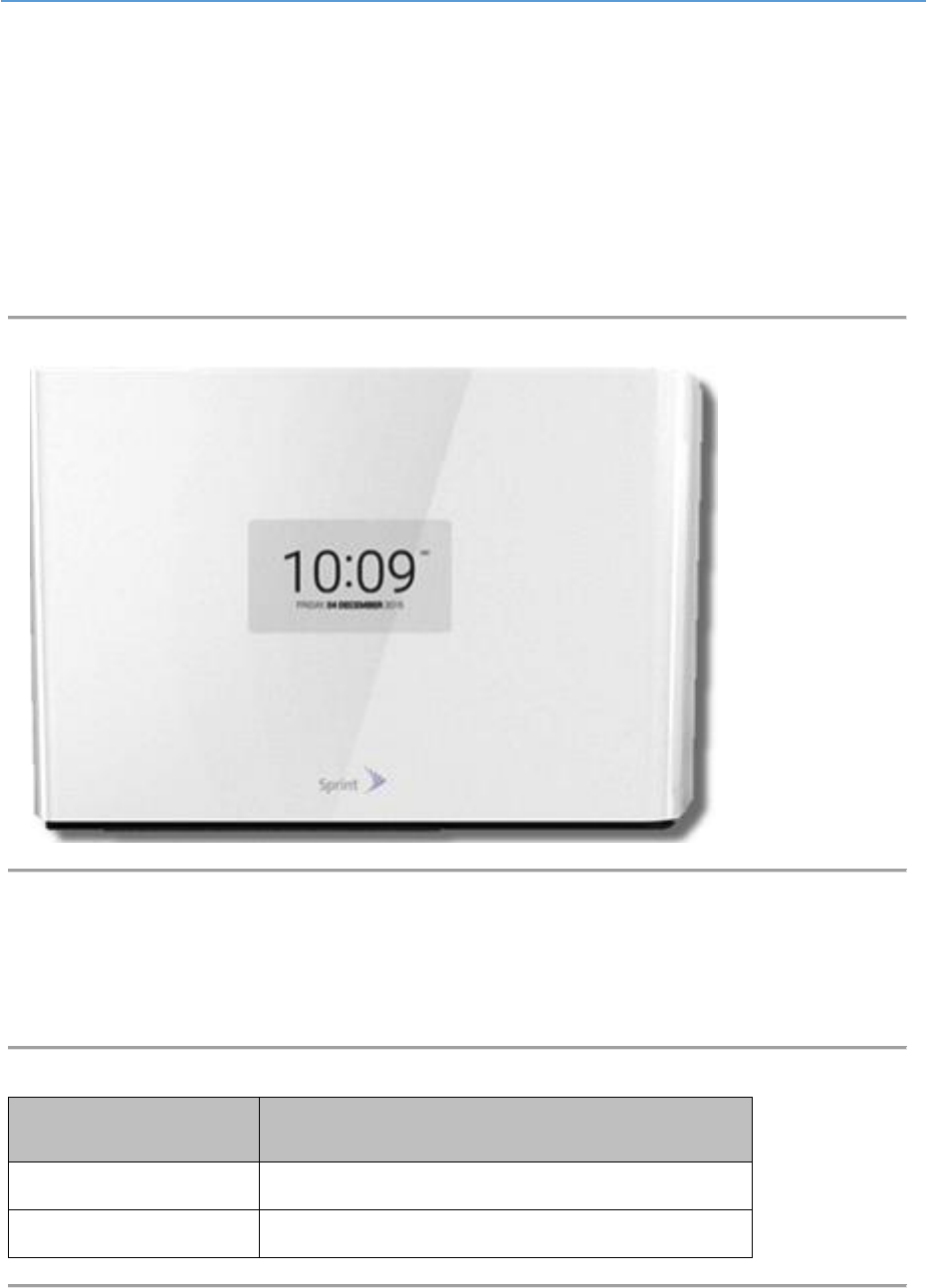
2.1 AirUnity 545 eNB 2.5GHz (B41)
The AirUnity 545 eNB B41.
Figure 1: AirUnity 545 eNB B41 - front
2.1.1 Physical Dimensions
The table below lists the physical dimensions of the AirUnity 545 eNB B41.
Table 6: AirUnity 545 eNB B41 Physical Dimentions
Parameter
Value
H x W x D
245mm x 333mm x 96mm
Weight
4Kg

AirUnity 545 eNB 2.5GHz (B41) User Guide
UGD-D01127 Airspan Commercial and Internal Use 14
2.1.2 Digital Display (Touch Screen)
AirUnity 545 unit has 5.17” digital touch display to allow user to interact with the device and obtain
following information:
Power on
RN-UE status
eNB status
Number of end user(s) connected
Location (GPS)
Macro received signal level
Best Location Indicator / Installation Instructions
Unit Reset (hidden mechanism)
The user interface provides information to enable the end user to determine the optimal location for
AirUnity 545 operation.
2.1.3 SIM Card
AirUnity 545 provides an embedded SIM and a standard SIM card holder for the operator-provided
SIM, (installed during assembly). Security details are provisioned for the RN-UE in the same fashion
and generally on the same systems as for the Access UEs.
2.2 Synchronisation
AS545 contains an integrated GPS receiver, which is used for location timing and synchronisation.
2.2.1 Synchronisation Compliance
AirUnity meets the synchronization requirements as they are defined in TS 36.104 and TS 36.133.
Inter eNodeB synchronization is supported to enable both 1PPS frame synchronization for TDD
interference avoidance and frequency synchronization for ICI avoidance.
2.2.2 Frequency Accuracy
For Frequency stability, the same source is used for RF frequency and data clock generation. The
modulated carrier frequency of the eNodeB has an accuracy of ±0.05ppm observed over a period of
one subframe (1ms).
2.2.3 Phase Accuracy
Phase accuracy, (required for TD-LTE interference coordination and for both TD-LTE and FDD-LTE
when considering MBSFN or ABS) is 1µs or better.
2.3 Power Supply
AirUnity 545 is powered via an AC mains (line power) adapter which provides local DC power to the
unit:
AC/DC power convertor supports:

AirUnity 545 eNB 2.5GHz (B41) User Guide
UGD-D01127 Airspan Commercial and Internal Use 15
AC input voltage range US: 100-240V±10% at 50/60Hz
DC output voltage range: 10V – 14V
DC cable length: 1.5M
2.4 Internal Battery
AirUnity 545 has an internal battery to support installation. The battery only supplies around 60
minutes power to the backhaul device to allow identification of the best backhaul location.
2.5 GPS Antenna
Table 7: GPS Antenna
Band
Function
Location
1575 MHz
GPS
Internal
Table 8: GPS Antenna Parameters
Parameter
GPS Band
L1
Frequency
1575.42 +3
Polarization
Right Hand Circular
Gain at 90° Elevation
4dBic

AirUnity 545 eNB 2.5GHz (B41) User Guide
UGD-D01127 Airspan Commercial and Internal Use 16
3 Hardware Security
3.1 Factory Generation of Device Key
Each device has a private key and associated certificate which is used to authenticate itself when
initiating communications. This private key is generated in the factory, and so is the corresponding
vendor certificate. This capability necessary in order to support large scale plug and play
deployments.
This device key is stored on the AirUnity 545 to allow it to authenticate to the network. If the private
key is compromised, then the device can be masqueraded by an attacker towards the operator’s core
network. Therefore, it is stored in an encrypted form.
In later releases a device-specific key will be introduced, this is a random number blown into on-SoC
eFuses during manufacture. This offers two points of additional protection namely: the key is not
discoverable by decompiling the code (an attacker will need to run code on the device in order to read
the eFuses); and the key can only be used to obtain the private key of a single device (because each
encryption key is unique).
3.2 Protected SIMs
The design of the systems provides the option to solder an embedded SIM to the board instead of
using a removable SIM; this removes the temptation to steal the SIM. Additionally, the operator can
ensure that these SIMs can only be used with the Relay APN, which would make them unusable with
an ordinary mobile phone (because relay traffic uses nested GTP-U tunnels).
3.3 Unused Port Security
Unused interfaces on the SoCs within AirUnity 545 are protected against attack by ensuring that the
corresponding pins are not connected to tracks on the circuit board. In addition to this hardware
protection the device drivers within the SoCs which service these ports are disabled.
3.4 Tamper Detection
Simple tamper detection is provided in AirUnity 545 by the use of tamper-evident labels.
Hardware Ready for Secure Boot
The SoCs within the AirUnity 545 unit supports secure boot. This is to be enabled by a software
download in a later release. Enabling secure boot ensures that only trusted software will run on the
SoCs internal to AirUnity 545.
AirUnity 545 eNB 2.5GHz (B41) User Guide
UGD-D01127 Airspan Commercial and Internal Use 17
4 Installation
Note: Please refer to the included Quick Start Guide to find best location and how to install the
AirUnity 545.
Note: The optimal window for the AirUnity 545 is the side of the building with a direct line of sight to
the provider’s tower
The AirUnity 545 unit is placed on the windowsill to receive the signal from outdoors and boost it
indoors. The following steps instruct on the proper positioning of the AirUnity 545 unit for optimal
service.
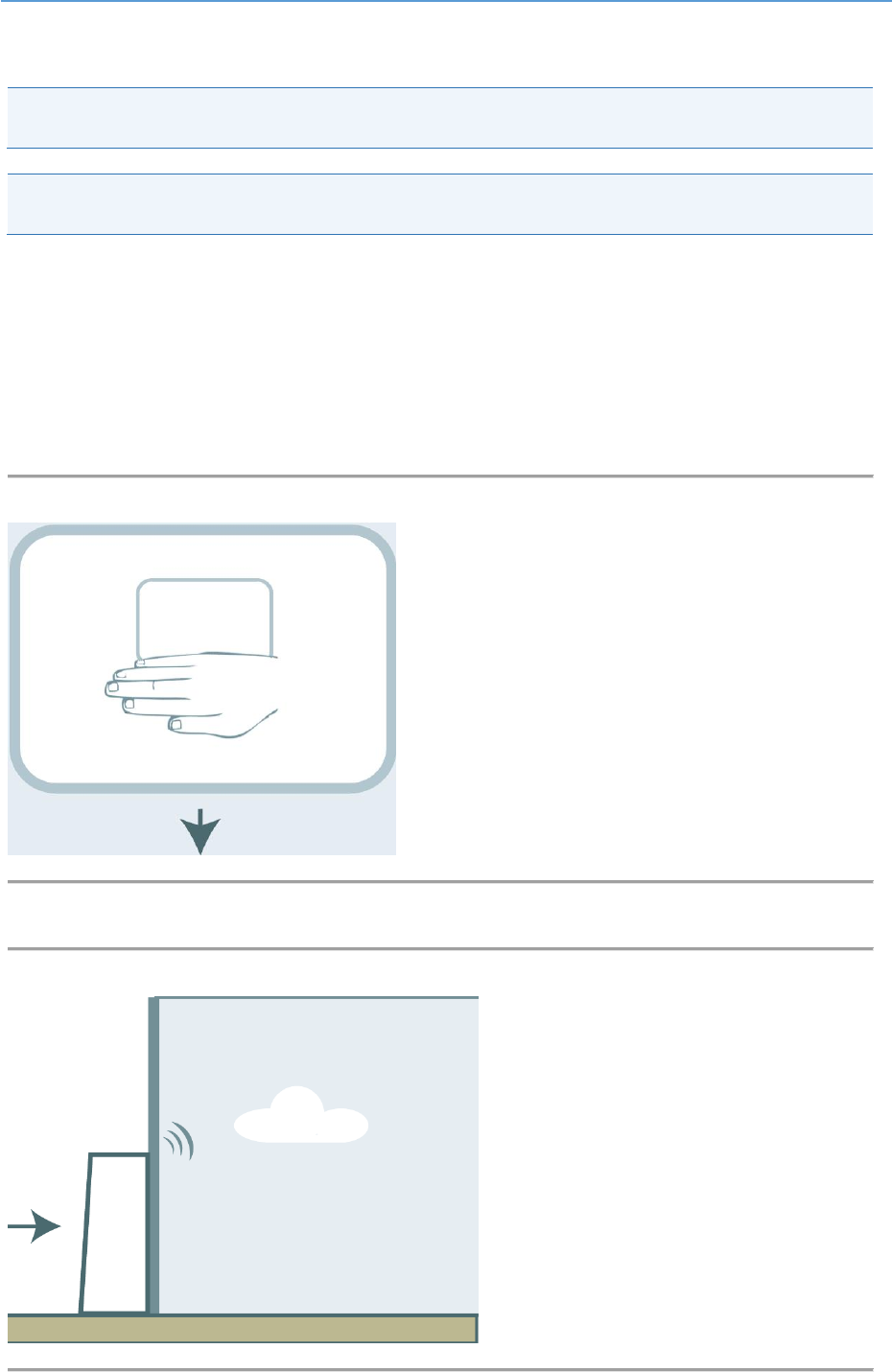
1. Remove the AirUnity 545 unit from the packaging.
2. Remove the Power Supply (included) from the packaging.
3. Place your hand on the unit blow the screen for two (20 seconds and remove it in order to
start the unit, as shown below:
Figure 2: Initial start
4. Place unit against a suitable window and tap Test Location.
Figure 3: Place on Windowsill
AirUnity 545 eNB 2.5GHz (B41) User Guide
UGD-D01127 Airspan Commercial and Internal Use 18
Note: Windows must be close to an available power supply outlet.
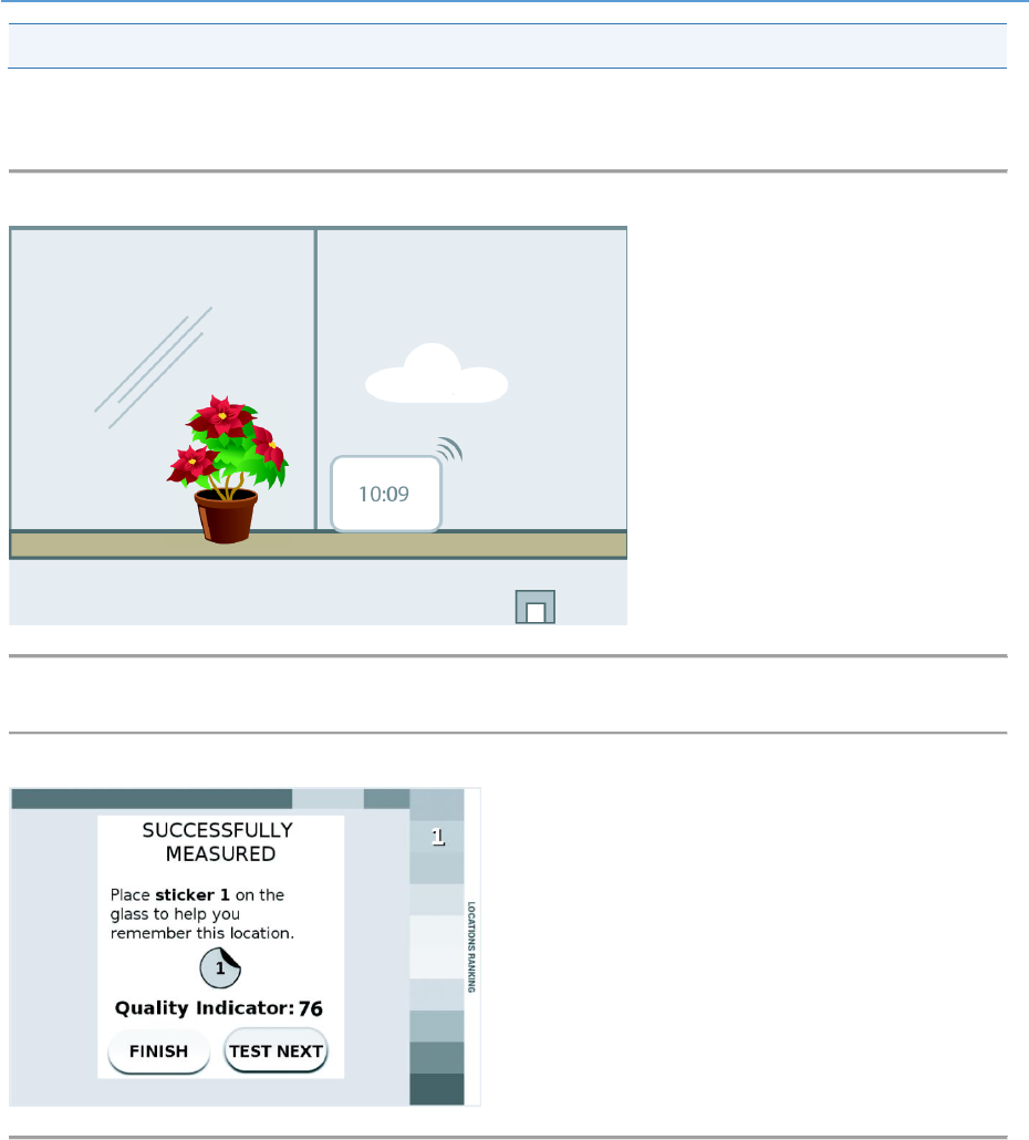
5. Wait while the service strength is measured. The Setup Wizard will indicate when to move
the unit.
Figure 4: Test for Best Location
6. Check results, compare and place the unit on the best windowsill position.
Figure 5: Check Results and Reposition
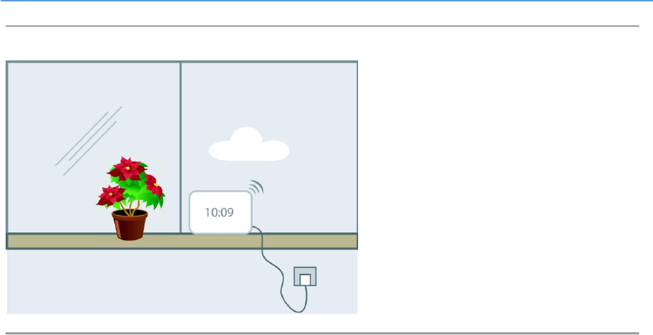
7. Connect unit to permanent charger and wait 2-3 minutes.
AirUnity 545 eNB 2.5GHz (B41) User Guide
UGD-D01127 Airspan Commercial and Internal Use 19
Figure 6: Final position plugged in
8. You are done.

AirUnity 545 eNB 2.5GHz (B41) User Guide
UGD-D01127 Airspan Commercial and Internal Use 20
5 Management and Configuration
AirUnity 545 supports FCAPS capabilities including the following:
Configuration Management
Inventory Management
Fault Management
Performance Management
Software Management
Diagnostics
AirUnity 545 is managed via remotely via Airspan’s EMS (Netspan) using SNMP and supports
management using a default IP address. The EMS is automatically detected via plug and play
procedures implemented in the AirUnity 545 and Netspan software.
Airspan’s Netspan element management system supports management of all Airspan products.

AirUnity 545 eNB 2.5GHz (B41) User Guide
UGD-D01127 Airspan Commercial and Internal Use 21
6 Standards Compliance
6.1 CE Marking
AirUnity 545 conforms to the European Union R&TTE Directive, and is therefore CE marked
accordingly.
6.2 Environmental
AirUnity 545 meets the following environmental requirements:
ETSI EN 300-019-1-3 Operational (weather protected locations)
ETSI EN 300-019-1-1 Storage (weather protected, not temperature controlled locations)
ETSI EN 300-019-1-2 Transportation
Table 9: Environmental Compliance
Type
Details
Standard Compliance
Operating temperature
-5°C to 45°C
ETSI 300 019 1-3 Class 3.1
Operating humidity
5% - 85% non-condensing
ETSI 300 019 1-3 Class 3.1
Storage temperature
-20°C to 70°C
N/A
Storage humidity
5% - 95% non-condensing
N/A
Rain and dust ingress
protection
IP40
N/A
Operational altitude
70-106 kPa as well as:
From -60m to 1800m @ 40C
From 1800m to 4000m @ 30C
N/A
Solar radiation
700 W/m2
ETSI 300 019 1-3 Class 3.1
6.3 EMC
Complies with the EMC requirement as specified by ETSI EN 301 489-1 V1.9.2 (2011-09) Class A, as
well as EN 301 489-4 V1.4.1 (2009-05) and IEC61000-4 series.
6.4 Safety
Conforms to IEC 60950, UL 60950, and EN 60950-1:2006.
In addition to this specification, the following specifications covering human exposure to radio
frequency electromagnetic fields are also met:
EN 50385:2002 Product standard to demonstrate the compliances of radio base stations and
fixed terminal stations for wireless telecommunication systems with the basic restrictions or
the reference levels related to human exposure to radio frequency electromagnetic fields (110
- 40 GHz). General public.

AirUnity 545 eNB 2.5GHz (B41) User Guide
UGD-D01127 Airspan Commercial and Internal Use 22
EN 50401:2006 Product standard to demonstrate the compliance of fixed equipment for radio
transmission (110 - 40 GHz) intended for use in wireless telecommunication networks with the
basic restrictions or the reference levels related to general public exposure to radio frequency
electromagnetic fields, when put into service.
6.5 ROHS & WEEE Compliance
The chemical content of the equipment and its packaging meets the EU ROHS directive -
2002/95/EC (ROHS) – compliant with ROHS6 (up to 2009)
The WEEE symbol is present on the product label as per the requirements of European
directive 2002/96/EC
6.6 Reliability and Maintenance
The AirUnity 545 contains no user-serviceable parts. The following reliability data assumes worst
case requirements. Overall reliability is improved when considering the dual transceivers as a
redundancy factor (this consideration is not included in the quoted figures).
Average Mean Time between Failures (MTBF) = 10 years.

AirUnity 545 eNB 2.5GHz (B41) User Guide
UGD-D01127 Airspan Commercial and Internal Use 23
A Abbreviations
Term
Expansion
3GPP
3rd Generation Partnership Project, responsible for LTE
AV-eNB
AirVelocity eNodeB
BER
Bit Error Rate
CN
Core Network
CP
Cyclic Prefix
dB
Decibel. A logarithmic unit used to describe a ratio (such as power ratio in
radio telecommunications)
dBm
An abbreviation for the power ratio in decibels (dB) of the measured power
referenced to one milliwatt (mW). It is used as a convenient measure of
absolute power because of its capability to express both very large and very
small values in a short form
DL
Downlink
EMS
Element Management System
eNodeB
Evolved Node B, is the element in E-UTRAN of LTE
ESP
Encapsulating Security Payloads (ESP) provide confidentiality, data-origin
authentication, connectionless integrity, an anti-replay service (a form of
partial sequence integrity), and limited traffic-flow confidentiality
E-UTRAN
Evolved Universal Terrestrial Radio Access Network, is the air interface of
3GPP's Long Term Evolution
FDD
Frequency-Division Duplexing. A transceiver mode where the transmitter and
receiver operate at different carrier frequencies
GPS
Global Positioning System
IPsec
Internet Protocol Security is a protocol suite for securing Internet Protocol
(IP) communications by authenticating and encrypting each IP packet of a
communication session
LED
Light Emitting Diode
LTE
Long Term Evolution
MAC
Medium Access Controller – responsible for several functions such
Scheduling, Packet (De) Multiplexing, etc…
MCS
Modulation and Coding Scheme
MIMO
Multiple-Input Multiple-Output
MME
Mobility Management Entity is the key control-node for the LTE access-
network. It is responsible, among other things for idle mode UE tracking and
paging procedure including retransmissions
MTBF
Mean Time Between Failures
OFDMA
Orthogonal Frequency-Division Multiple Access (OFDMA) is a multiple
access version of OFDM digital modulation scheme, used for eNodeB
transmissions to UEs
PDCP
Packet Data Convergence Protocol. A Sub-Layer in LTE responsible for
Security, IP Header (De) Compression, etc…
PTP
Precision Time Protocol is used to synchronize clocks throughout a network.
In this document, PTP is referring to IEEE1588-2008 protocol
QAM
Quadrature Amplitude Modulation
QPSK
Quadrature Phase Shift Keying
RB
Resource Block
RLC
Radio Link Control. A Sub-Layer in LTE responsible for Ack/Nack, error
correction, packet reordering, etc…
ROHS
Restriction Of Hazardous Substances
RRC
Radio Resource Control. A Sub-Layer in LTE responsible for Broadcast of
system information, paging, security functions, radio bearer control, etc…
RRM
Radio Resource Management is used to cover all functions that are related
to the assignment and sharing of radio resources among UEs
SC-FDMA
Single-Carrier FDMA is a frequency-division multiple access scheme, dealing
with the assignment of multiple users to a shared communication resource.
Used in LTE for UE transmissions to the eNodeB
SDR
Software Defined Radio
TDD
Time-Division Duplexing. A transceiver mode where the transmitter and
receiver operate on the same carrier frequency
UE
User Equipment. The end user in LTE

AirUnity 545 eNB 2.5GHz (B41) User Guide
UGD-D01127 Airspan Commercial and Internal Use 24
Term
Expansion
UL
Uplink
WEEE
Waste Electrical and Electronic Equipment