Airspan Networks H4K425 Base station of LTE fixed cellular system User Manual AirHarmony 4400 ext Installation Guide
Airspan Networks Inc Base station of LTE fixed cellular system AirHarmony 4400 ext Installation Guide
Users Manual

AirHarmony-4400 Installation Guide
External Cavity Filters
Part Number: UGD-D01186
System Release: 15.0
Revision: A
Published: December 2016

© Copyright by Airspan Networks Ltd., 2016-2016. All rights reserved worldwide.
Legal Notices
The information contained within this document is proprietary, privileged and intended only for the recipient. As such, the
information is subject to all relevant copyright, patent and other laws protecting intellectual property, as well as any
specific agreements protecting Airspan Networks Ltd. rights in the aforesaid information. Neither this document nor the
information contained herein may be published, reproduced, transmitted or disclosed to third parties, in whole or in part,
without the express, prior, written permission of Airspan Networks Ltd. In addition, any use of this document or the
information contained herein for the purposes other than those for which it is disclosed is strictly forbidden.
Airspan Networks Ltd. reserves the right, without prior notice or liability, to make changes in equipment design or
specifications.
Information supplied by Airspan Networks Ltd. is believed in good faith to be accurate and reliable, while every care has
been taken in preparing these documents. However, Airspan Networks Ltd. does not make any representations and gives
no warranties of whatever nature in respect of these documents, including without limitation, the accuracy or
completeness of any information, facts and/or opinions contained therein. No responsibility is assumed by Airspan
Networks Ltd. for the use of the documents nor for the rights of third parties which may be effected in any way by the use
thereof. The provision of these documents (and the documents themselves) does not constitute professional advice of any
kind. Any representation(s) in these documents concerning performance of Airspan Networks Ltd. product(s) are for
informational purposes only and are not warranties of future performance, either expressed or implied. Airspan Networks
Ltd., its affiliates, directors, employees and agents shall not be held liable for any damages or losses, of any nature
whatsoever, arising from any use of and/or reliance on the documents.
These documents may contain flaws, omissions or typesetting errors; no warranty is granted nor liability assumed in
relation thereto unless specifically undertaken in Airspan Networks Ltd. sales contract or order confirmation. Information
contained herein is periodically updated and changes will be incorporated into subsequent editions. If you have
encountered an error, please notify Airspan Networks Ltd.
Product performance figures quoted within this document are indicative and for information purposes only.
UK WEEE Registration number: WEEE/AB0207WZ. For more information, see WEEE Information for Airspan
Customers and Recyclers.
Acknowledgements
© Intel Corporation http://www.intel.com/
© Microsoft Corporation http://www.microsoft.com

UGD-D01186 Airspan Commercial and Internal Use i
Table of Contents
Document Information ...................................................................................... 2
Abstract ................................................................................................................................. 2
Revision History ..................................................................................................................... 2
Warnings and Cautions ...................................................................................... 3
Human Exposure to Radio Frequencies ................................................................................ 3
Radio Interference ................................................................................................................ 3
Modifications ........................................................................................................................ 3
General .................................................................................................................................. 3
Général .................................................................................................................................. 3
Important Safety Instructions ......................................................................................... 4
Safety ..................................................................................................................................... 4
Securite.................................................................................................................................. 5
Warning of Hazardous Voltages ............................................................................................ 5
Attention aux Voltages Hasardeux ........................................................................................ 5
Adherence to European Directive 1999/5/EC ....................................................................... 6
Warning Symbols .................................................................................................................. 6
Service Information ............................................................................................................... 6
UL Information ...................................................................................................................... 7
Lightning Protection .............................................................................................................. 7
Outdoor Ethernet Cabling ..................................................................................................... 8
DECLARATION OF CONFORMITY ........................................................................................... 8
GPS Compliance .................................................................................................................... 9
Maximum Output TX Total Power ...................................................................... 9
Power Consumption ............................................................................................................ 10
Antenna System .................................................................................................................. 10
Long Switched Beam Antenna ............................................................................................ 10
External Antenna ................................................................................................................. 11

AirHarmony-4400 (External Cavity Filters) Installation Guide
UGD-D01186 Airspan Commercial and Internal Use ii
About This Document ...................................................................................... 12
Purpose ............................................................................................................................... 12
Intended Audience .............................................................................................................. 12
Document Conventions ....................................................................................................... 12
Document Organization ...................................................................................................... 13
Related Reading .................................................................................................................. 13
Customer Care Help Desk ................................................................................ 14
Airspan Encourages Comments .......................................................................................... 14
1 Introduction ................................................................................................. 15
1.1 AirHarmony-4400 ........................................................................................................ 15
1.2 Deployment ................................................................................................................. 15
2 Getting Started ............................................................................................ 17
2.1 Workflow of Installation .............................................................................................. 17
2.2 AirHarmony-4400 Installation Checklist ...................................................................... 18
3 Verifying Prerequisites ................................................................................. 18
3.1 Verifying Site Requirements ........................................................................................ 18
3.2 Verify Installation Requirements ................................................................................. 18
3.2.1 Verify the Tools ........................................................................................................... 18
3.2.2 Verify the Parts and Kits .............................................................................................. 19
3.2.3 Power Supply and Current .......................................................................................... 21
3.2.4 Panels .......................................................................................................................... 22
3.2.5 Physical Dimensions .................................................................................................... 23
3.2.6 Environmental ............................................................................................................. 24
4 Installing AirHarmony-4400 ......................................................................... 25
4.1 Rear External Filter Set Assembly ................................................................................ 25
4.2 Front External Filter Set Assembly .............................................................................. 28
4.3 Connecting the GPS Antenna ...................................................................................... 33
4.4 Pole/Wall Mount Assembly ......................................................................................... 35
4.4.1 Mounting on a Wooden Pole ...................................................................................... 35

AirHarmony-4400 (External Cavity Filters) Installation Guide
UGD-D01186 Airspan Commercial and Internal Use iii
4.4.2 Mounting on a Non-Wooden Pole .............................................................................. 37
4.4.3 Mounting on a Wall ..................................................................................................... 38
4.5 Securing AirHarmony-4400 to the Mounting Plate ..................................................... 40
5 AirHarmony-4400 Connections .................................................................... 44
5.1 Grounding .................................................................................................................... 44
5.2 Remote Antenna Assembly ......................................................................................... 44
5.2.1 Connecting RF Jumper Cables to External Antenna .................................................... 44
5.2.2 Weather-proofing the Antenna Connections ............................................................. 45
5.3 Cable Connections ....................................................................................................... 46
5.3.1 Copper Ethernet Cable Assembly ................................................................................ 46
Assembly Instructions ............................................................................................................. 46
5.4 Fiber Ethernet (SFP) Cable Installation ........................................................................ 47
5.4.1 SFP Cable Connection .................................................................................................. 47
5.5 Connecting the AC Power Cable to AirHarmony-4400 ................................................ 49
5.5.1 Power Cable Preparation ............................................................................................ 49
5.5.2 Securing Connector Clamp .......................................................................................... 53
A Job Sheet ..................................................................................................... 54
B Abbreviations ............................................................................................... 55
Figures
Figure 1: AirHarmony-4400 with external cavity filters & cover .......................................................... 11
Figure 2: AirHarmony-4400 with Front & Rear Filter Sets & cover ...................................................... 16
Figure 3: Workflow................................................................................................................................ 17
Figure 4: AirHarmony-4400 Unit, Bottom panel ................................................................................... 22
Figure 5: AirHarmony-4400 Unit, Top panel ......................................................................................... 23
Figure 6: AIrHarmony-4400 - in Horizontal Position prior to Rear External Filters Set Assembly ........ 25
Figure 7: Rear External Filters' Set ........................................................................................................ 26
Figure 8: Mounting Rear External Filters' set ....................................................................................... 26
Figure 9: Back Bracket Assembly .......................................................................................................... 27
Figure 10: Fitting RF Connector ............................................................................................................ 27
Figure 11. Tighten the Filter Screws ..................................................................................................... 27
Figure 12: Tighten Hex Head Bolts ........................................................................................................ 28
Figure 13: AIrHarmony-4400 in Prone Position Prior to Front External Filter Assembly...................... 28
Figure 14: External Filters' Set .............................................................................................................. 29

AirHarmony-4400 (External Cavity Filters) Installation Guide
UGD-D01186 Airspan Commercial and Internal Use iv
Figure 15: External Filters' Set slots & fastenings ................................................................................. 29
Figure 16: Mounting External Filters' set on Sun-shield ....................................................................... 30
Figure 17: Opening cover ...................................................................................................................... 30
Figure 18. Cover opened ....................................................................................................................... 31
Figure 19: Align and fit filter to connector ............................................................................................ 31
Figure 20: Tighten screws on filter........................................................................................................ 32
Figure 21: Align and fit second filter to connector ............................................................................... 32
Figure 22: Tighten filter bridge screws on Sun-Shield .......................................................................... 33
Figure 23: Tighten screws on cover ...................................................................................................... 33
Figure 24: Attaching GPS antenna to unit ............................................................................................. 34
Figure 25: Pole/Wall mounting plate .................................................................................................... 35
Figure 26: Mounting plate on pole ....................................................................................................... 36
Figure 27: Through-bolt & Mounting plate ........................................................................................... 37
Figure 28: Pole/Wall mounting plate (w/o bolt) ................................................................................... 37
Figure 29: Mounting plate mounted ..................................................................................................... 38
Figure 30: Mounting Plate on Wall ....................................................................................................... 39
Figure 31: Lift unit and fit the slotted holes unto studs on top of mounting plate .............................. 40
Figure 32: Align Pins .............................................................................................................................. 41
Figure 33: AirHarmony mounted on Wooden Pole .............................................................................. 41
Figure 34: AirHarmony mounted on Concrete Pole ............................................................................. 42
Figure 35: AirHarmony being mounted on a Wall ................................................................................ 43
Figure 36: Grounding ............................................................................................................................ 44
Figure 37: DIN 4.1/9.5 connectors (external thread) ............................................................................ 45
Figure 38: Gland connector - copper .................................................................................................... 46
Figure 39: Ethernet Cable through connector ...................................................................................... 46
Figure 40: LC duplex cable assembly .................................................................................................... 47
Figure 41: Cable connector hook up to the board connector .............................................................. 47
Figure 42: Slide on inner housing .......................................................................................................... 48
Figure 43: Slide over and click ............................................................................................................... 49
Figure 44: AC connector ........................................................................................................................ 49
Figure 45: AC Connector disassembled ................................................................................................ 50
Figure 46: Strip wire .............................................................................................................................. 50
Figure 47: power cable assembly .......................................................................................................... 50
Figure 48: Connector on cable .............................................................................................................. 50
Figure 49: Plug pins ............................................................................................................................... 51
Figure 50: Pin assignment ..................................................................................................................... 51
Figure 51: Attaching wires .................................................................................................................... 51
Figure 52: Connector Clamp ................................................................................................................. 52
Figure 53: Power cable attached to AirHarmony-4400 ........................................................................ 52
Figure 54: Securing the connection ...................................................................................................... 53
Tables
Table 1: AirHarmony-4400DF B41 Full Band FCC Maximum Output TX Total Power............................. 9
Table 2: AirHarmony-4400DH B41 High Band FCC Maximum Output TX Total Power .......................... 9
Table 3: AirHarmony-4400DL B41 Low Band FCC Maximum Output TX Total Power .......................... 10
Table 4: AirHarmony-4400 ETSI Maximum Output TX Total Power ..................................................... 10
Table 5: Power Consumption ................................................................................................................ 10

AirHarmony-4400 (External Cavity Filters) Installation Guide
UGD-D01186 Airspan Commercial and Internal Use v
Table 6: Typographic Conventions ........................................................................................................ 12
Table 7. Minimum Hardware Requirements ........................................................................................ 18
Table 8. Parts & Kits .............................................................................................................................. 19
Table 9. Amperage Draw....................................................................................................................... 22
Table 10: AirHarmony-4400 Physical Dimensions ................................................................................ 23
Table 11: AirHarmony-4400 Environment Compliance ........................................................................ 24
Table 12: Job Sheet ............................................................................................................................... 54

AirHarmony-4400 (External Cavity Filters) Installation Guide
UGD-D01186 Airspan Commercial and Internal Use 2
Document Information
Abstract
This document details procedures for installing the Airspan’s AirHarmony-4400 EXT, a Macro-class
eNodeB variant and its place in the Airspan product suite. This document is intended for qualified
personnel with a working knowledge of LTE.
Revision History
Revision Details
Date
Summary of Changes
Rev 0.1
November 2016
Initial document – draft
Comments
Rev A
December 2016
Publish

AirHarmony-4400 (External Cavity Filters) Installation Guide
UGD-D01186 Airspan Commercial and Internal Use 3
Warnings and Cautions
Human Exposure to Radio Frequencies
The AirHarmony-4400 antennas should be operated from a minimum safe distance of 4.6m
Radio Interference
The AirHarmony generates, uses, and can radiate radio frequency energy and, if not installed and
used in accordance with the instructions, may cause harmful interference to radio communications.
However, there is no guarantee that interference will not occur in a particular installation. If this
equipment does cause harmful interference to radio or television reception, which can be
determined by turning the equipment on and off, the technician is encouraged to try to correct the
interference by performing one or more of the following measures:
Re-orientate or relocate the unit
Increase separation between the units and/or End Devices
Connect the equipment to a circuit different from that to which the power source is
connected
Modifications
Any changes and modifications to this device that are not expressly approved by Airspan Networks
may void the user's authority to operate the equipment.
General
Only qualified personnel should be allowed to install, replace, and service the equipment.
The device cannot be sold retail, to the general public or by mail order. It must be sold to
operators.
Installation must be controlled.
Installation must be performed by licensed professionals.
Installation requires special training. The AirHarmony-4400 should be installed ONLY by
experienced installation professionals who are familiar with local building and safety codes
and, wherever applicable, are licensed by the appropriate government regulatory
authorities. Failure to do so may void Airspan's product warranty and may expose the end
user or the service provider to legal and financial liabilities. Airspan and its resellers or
distributors are not liable for injury, damage or violation of regulations associated with the
installation of outdoor units or antennas.
The device is to be installed in a Restricted Access Location.
Surge Arrestors and Transient Voltage Surge Suppressors installed external to the ITE are
required to comply with the appropriate CEC/NEC requirements.
Général
Seul le personnel qualifié peut être autorisé pour installer ou remplacer l’équipement ainsi
qu’effectuer les opérations de maintenance pour cet équipement.
L’équipement ne peut pas être vendu en grande distribution ou par commande via email à
destination du public. Il doit être vendu aux opérateurs de télécommunications.
Son installation doit être contrôlée.
Son Installation doit être effectuée par des professionnels autorises.

AirHarmony-4400 (External Cavity Filters) Installation Guide
UGD-D01186 Airspan Commercial and Internal Use 4
Son installation requiert une formation spécifique du personnel. L’AirHarmony-4400, radio
et antenne doit être installe UNIQUEMENT par des installateurs professionnels
expérimentés et ayant une connaissance des constructions locales et règles de sécurité, ainsi
que, dès que nécessaire, disposant d’un agreement des autorités gouvernementales de
régulation. Toute enfreinte a ces obligations peut annuler la garantie délivrée par Airspan
pour ces produits et peut exposer l’utilisateur final ou le fournisseur de services a des
dommages légaux et financiers.
Airspan et ses revendeurs ou ses distributeurs ne sont pas responsables des blessures,
dommages ou violations de la régulation en vigueur lies a l’installation du système extérieur
ou des antennes.
L’Equipment doit être installe dans une zone a accès réduit et contrôle.
Parafoudres et Protections contre les surtensions transitoires doivent etre installés a
l’exterieur de l’équipement ITE sont tenus de se conformer aux exigences relatives aux
normes CEC/NEC concernées
Important Safety Instructions
Read and Save these instructions
This Installation Guide contains instructions and warnings that should be followed during
installation, and operation.
Failure to follow these instructions could cause bodily injury and/or product failure
Safety
1. Read this guide and follow all operating and safety instructions.
2. Static sensitive components inside - do not remove the lid or base: No user serviceable
parts inside.
3. The ground connection should be made before connecting to supply connections.
4. Position the power cord to avoid possible damage; do not overload circuits.
5. Do not place this product on or near a direct heat source, and avoid placing objects on
the terminal.
6. To avoid electrical shock do not install this device during adverse conditions such as rain
or inclement weather.
7. Use only a damp cloth for cleaning. Do not use liquid or aerosol cleaners. Disconnect the
power before cleaning.
8. The units should not be located too near power lines or other electrical power circuits,
where it can come into contact with such power lines or circuits.
9. The radio transceiver must be properly grounded to protect against power surges and
accumulated static electricity. It is the user’s responsibility to install this device in
accordance with the local electrical codes.
10. Installation of the AirHarmony-4400 must be contracted to a professional installer.
11. The circuit breaker should be easily accessible in case you have to disconnect the device.
12. When installed in the final configuration, the product must comply with the applicable
Safety Standards and regulatory requirements of the country in which it is installed. If
necessary, consult with the appropriate regulatory agencies and inspection authorities
to ensure compliance.

AirHarmony-4400 (External Cavity Filters) Installation Guide
UGD-D01186 Airspan Commercial and Internal Use 5
Securite
1. Lire attentivement ce guide et suivre les instructions d’utilisation et de sécurité.
2. Des composants sensibles a électricité statique sont utilisés à l’intérieur. Ne pas retirer le
coffre ou la base. Aucune pièce a l’intérieur est d’utilité pour l’utilisateur.
3. La connexion "terre" doit être effectuée en priorité et avant d'effectuer les connexions à
la source d'alimentation (phase et neutre).
4. Positionner le cordon d’alimentation de façon à éviter des dommages potentiels. Ne pas
surcharger les circuits.
5. Ne pas placer ce produit sur ou à proximité d’une source directe de chaleur et éviter de
placer des objets sur le terminal.
6. Afin d’éviter des problèmes électriques, ne pas installer cet équipement au cours
d’évènements climatiques difficiles comme averses ou météo non clémente.
7. Utiliser uniquement chiffon de coton pour nettoyage. Ne pas utiliser de produits liquides
ou d’aérosols. Déconnecter le produit de la source d’alimentation avant nettoyage.
8. L’unité ne doit pas être située trop près de lignes électriques ou autres circuits de
puissance, avec lesquels il pourrait entrer en contact.
9. L’émetteur radio doit être correctement relie a la terre afin de le protéger contre les
surtensions ou accumulation d’électricité statique. L’utilisateur est tenu responsable de
l’installation du produit conformément aux règles électrique en vigueur localement.
10. L’installation de AirHarmony-4400 doit être contractualisée avec un installateur
professionnel.
11. L’interrupteur de circuit électrique doit être facilement accessible afin de pouvoir
déconnecter l’équipement.
12. Lors de l’installation de la configuration finale, le produit doit être conforme aux
Standards de Sécurité en vigueur ainsi qu’aux exigences réglementaires du pays dans
lequel il est installé. Si nécessaire, consulter les agences règlementaires appropriées,
ainsi que les autorités chargées de l’inspection afin de garantir la conformité.
Warning of Hazardous Voltages
On AC installations, hazardous voltages exist. Use caution when verifying or working with AC power.
Remove metal jewelry that could come into contact with AC power.
On DC sections, short-circuiting the low voltage, low impedance circuits can cause severe arcing that
may result in burns or eye damage. Remove rings, watches etc. to avoid shorting DC circuits.
Note: Airspan products do not contain hazardous substances (as defined in UK Control of
Substances Hazardous to Health Regulations 1989 and the Dangerous Substances Regulations
1990). At the end of any Airspan products life cycle, the customer should consult with Airspan to
ensure that the product is disposed of in conformance with the relevant regulatory requirements.
Attention aux Voltages Hasardeux
Sur les installations de réseau électrique de type courant alternatif (CA), des voltages hasardeux
peuvent survenir. Garder une Attention particulière lors d’une vérification ou de travaux sur réseau
électrique CA. Retirer tous bijoux en métal qui pourraient entrer en contact avec l’alimentation ou le
réseau CA.
AirHarmony-4400 (External Cavity Filters) Installation Guide
UGD-D01186 Airspan Commercial and Internal Use 6
Sur les portions de réseau électrique de type courant continu (CC), un circuit basse impédance peut
causer de sérieux arcs électriques qui pourraient bruler ou endommager les yeux. Retirer bagues,
anneaux, montres etc… afin d’éviter les court-circuit sur le réseau CC.
Adherence to European Directive 1999/5/EC
European Council Recommendation 1999/5/EC details basic restrictions and reference levels on
human exposure to electromagnetic fields as advised by the ICNIRP. Adherence to these
recommended restrictions and reference levels should provide a high level of protection as regards
the established health effects that may result from exposure to electromagnetic fields.
Airspan equipment is compliant with CE and R&TTE regulations and can be operated in all EU
(European Union) locations listed below:
Country Code
BE
EL
LT
PT
BG
ES
LU
RO
CZ
FR
HU
SI
DK
HR
MT
SK
DE
IT
NL
FI
EE
CY
AT
SE
IE
LV
PL
UK
Warning Symbols
The following symbols may be encountered during installation or troubleshooting. These warning
symbols mean danger. Bodily injury may result if you are not aware of the safety hazards involved in
working with electrical equipment and radio transmitters. Familiarize yourself with standard safety
practices before continuing.
Caution, hot surface
Caution
Electro-Magnetic
Radiation
High Voltage
Service Information
Refer all repairs to qualified service personnel. Do not modify any part of this device, as this will void
the warranty.
Disconnect the power to this product and return it for service if the following conditions apply:

AirHarmony-4400 (External Cavity Filters) Installation Guide
UGD-D01186 Airspan Commercial and Internal Use 7
a. The terminal does not function after following the operating instructions outlined in this
manual.
b. The product has been dropped or the housing is damaged.
Locate the serial number of the terminal and record this on your registration card for future
reference. Also record the MAC address, located on the product sticker.
UL Information
- The equipment must be properly grounded according with NEC and other local safety code
requirements.
- Reminder to all the BWA system installers: Attention to Section 820-40 of the NEC which provides
guidelines for proper grounding and, in particular, specifies that the cable ground shall be connected
to the grounding system of the building, as close to the point of cable entry as is practical.
- AirHarmony-4400 is designed to operate in environmental conditions complying with IP66 and
relevant standards.
Lightning Protection
WARNING: The following notes are general recommendations for the system. The wireless
equipment should be installed by a qualified professional installer and must follow local and national
codes for electrical grounding and safety. Failure to meet safety requirements and/or use of non-
standard practices and procedures could result in personal injury and damage to equipment. A direct
lightning strike may cause serious damage even if these guidelines are followed.
All outdoor wireless equipment is susceptible to lightning damage from a direct hit or induced
current from a near strike. Lightning protection and grounding practices in local and national
electrical codes serve to minimize equipment damage, service outages, and serious injury. Reasons
for lightning damage are summarized as:
- Poorly grounded tower/antenna sites that can conduct high lightning strike energy into equipment.
- Lack of properly installed lightning protection equipment that can cause equipment failures from
lightning induced currents.
A lighting protection system provides a means by which the energy may enter earth without passing
through and damaging parts of a structure. A lightning protection system does not prevent lightning
from striking; it provides a means for controlling it and preventing damage by providing a low
resistance path for the discharge of energy to travel safely to ground. Improperly grounded
connections are also a source of noise that can cause sensitive equipment to malfunction.
A good tower grounding system disperses most of the surge energy from a tower strike away from
the building and equipment.
To limit the equipment damage due to a lightning strike, the following practices are recommended
for the wireless system:
- Provide direct grounding from the antenna mounting bracket, the radio and antenna and the
lightning/surge protectors to the same ground point at the base of the tower or a ground bus on the
building. Use the grounding screws on the antenna bracket and the radio and antenna for
terminating the ground wires.

AirHarmony-4400 (External Cavity Filters) Installation Guide
UGD-D01186 Airspan Commercial and Internal Use 8
- The AC wall outlet ground must be connected to the same grounding system as the eNodeB.
Outdoor Ethernet Cabling
- Ethernet cable connected to should be outdoor grade with UV protection.
- Use shielded out CAT5e (minimum) cabled terminated with metallic RJ45 connectors.
- In order to protect the indoor unit, install surge protection circuits on all copper cables on their
entrance to the building.
- Surge protection circuit must use a minimum 16AWG grounding cable.
DECLARATION OF CONFORMITY
European Community, Switzerland, Norway, Iceland, and Liechtenstein
Declaration of Conformity with Regard to the R&TTE Directive 1999/5/EC
English:
This equipment is in compliance with the essential requirements and other relevant provisions of Directive
1999/5/EC.
Deutsch:
Dieses Gerät entspricht den grundlegenden Anforderungen und den weiteren entsprecheneden Vorgaben der
Richtlinie 1999/5/EU.
Dansk:
Dette udstyr er i overensstemmelse med de væsentlige krav og andre relevante bestemmelser i Directiv
1999/5/EF.
Español:
Este equipo cumple con los requisitos esenciales asi como con otras disposiciones de la Directive 1999/5/EC.
Greek:
ΜΕ ΤΗΝ ΠΑΡΟΥΣΑ Airspan ΔΗΛΩΝΕΙ ΟΤΙ Ο ΕΞΟΠΛΙΣΜΟΣ ΣΥΜΜΟΡΦΩΝΕΤΑΙ ΠΡΟΣ ΤΙΣ ΟΥΣΙΩΔΕΙΣ ΑΠΑΙΤΗΣΕΙΣ
ΚΑΙ ΤΙΣ ΛΟΙΠΕΣ ΣΧΕΤΙΚΕΣ ΔΙΑΤΑΞΕΙΣ ΤΗΣ ΟΔΗΓΙΑΣ 1999/5/ΕΚ.
Français:
Cet appareil est conforme aux exigencies essentialles et aux autres dispositions pertinantes de la Directive
1999/5/EC.
Íslenska:
Þessi búnaður samrýmist lögboðnum kröfum og öðrum ákvæðum tilskipunar 1999/5/ESB.
Italiano:
Questo apparato é conforme ai requisiti essenziali ed agli altri principi sanciti dalla Direttiva 1999/5/EC.
Nederlands:
Deze apparatuur voldoet aan de belangrijkste eisen en andere voorzieningen van richtlijn 1999/5/EC.
Norsk:
Dette utstyret er i samsvar med de grunnleggende krav og andre relevante bestemmelser i EU-directiv
1999/5/EC.
Português:
Este equipamento satisfaz os requisitos essenciais e outras provisões da Directiva 1999/5/EC.

AirHarmony-4400 (External Cavity Filters) Installation Guide
UGD-D01186 Airspan Commercial and Internal Use 9
Suomalainen:
Tämä laite täyttää direktiivin 1999/5/EY oleelliset vaatimukset ja on siinä asetettujen muidenkin ehtojen
mukainen.
Svenska:
Denna utrustning är i överensstämmelse med de väsentliga kraven och andra relevanta bestämmelser i
Direktiv 1999/5/EC.
Român:
Acest echipament este în conformitate cu cerinţele esenţiale şi alte prevederi relevante ale Directivei
1999/5/CE.
The Declaration of Conformity related to this product can be obtained from PLM@Airspan.com.
GPS Compliance
The GPS is in compliance with the essential requirements and other relevant provisions of Directive
1999/5/EC."
The GPS complies with the following EMC Common Regulatory Testing standards:
EN55022: Radiated and Conducted Emissions
CISPR 22: Class B
EN 50081-1: Generic Emissions Class B
EN 50082-1: Generic Immunity Class B
EN 61000-4-2: Electrostatic Discharge Immunity
EN 61000-4-3: Radiated RF EM Field Immunity Test
EN 61000-4-4: Electrical Fast Transient/Burst Test
EN 61000-4-6: Conducted Immunity
EN 61000-4-8: Magnetic Field Immunity
Note: A GPS is recommended for synchronizing between LTE sectors.
Note: An optional GPS Lightning/Surge protector is available from Airspan when installing the GPS
antenna in a remote location for lightning prone deployments.
Maximum Output TX Total Power
Table 1: AirHarmony-4400DF B41 Full Band FCC Maximum Output TX Total Power
Frequency Band
FCC
TX EIRP
Antenna Gain
2496 – 2690 MHz
46.20 dBm
64.20 dBm
18dBi
Table 2: AirHarmony-4400DH B41 High Band FCC Maximum Output TX Total Power
Frequency Band
FCC
TX EIRP
Antenna Gain
2618 – 2690 MHz
46.20 dBm
64.20 dBm
18dBi
AirHarmony-4400 (External Cavity Filters) Installation Guide
UGD-D01186 Airspan Commercial and Internal Use 10
Table 3: AirHarmony-4400DL B41 Low Band FCC Maximum Output TX Total Power
Frequency Band
FCC
TX EIRP
Antenna Gain
2496 – 2568 MHz
46.20 dBm
64.20 dBm
18dBi
Table 4: AirHarmony-4400 ETSI Maximum Output TX Total Power
Frequency Band
ETSI
TX EIRP
Antenna Gain
2496 – 2690 MHz
46 dBm
64 dBm
18dBi
Caution: Do not set maximum output TX power to higher than local regulations.
Power Consumption
AirHarmony-4400 power consumption is described in the following table:
Table 5: Power Consumption
Duplex
Tx Power at RF Port (dBm)
Nominal Power Consumption (W)
TDD- FC1
2 x 43
265
FDD
2 x 43
340
Antenna System
AirHarmony-4400 comes in a range of frequency variants that can be mounted with different
antenna options and formats. A typical installation will have a cross-polar sector or dual slant
antenna connected to the approprate Cavity filter of the AirHarmony-4400 variant unit. Various
antennas are designed specifically for AirHarmony-4400 deployments; specifications are available
from Airspan separately.
Long Switched Beam Antenna
Long Switched Beam antenna variant includes a steerable antenna mounted on the unit with the
following specification. The antenna is a multi-element cross polarized (dual slant) design which can
be used in directional or Omni modes of operation.
Scenario #1 - The long switched beam antenna is mounted directly on the unit and connected via its
two RF ports and the control port. The GPS antenna is either mounted on the top of the unit (if
conditions allow) or mounted separately with approved lightning protection.
Scenario #2 - The long switched beam antenna is mounted on the pole above the unit connected via
its two RF ports and the control port.
AirHarmony-4400 (External Cavity Filters) Installation Guide
UGD-D01186 Airspan Commercial and Internal Use 11
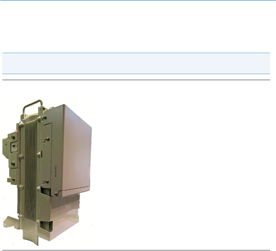
External Antenna
The externally mounted antenna should be a dual slant or cross polarized fixed antenna which are
connected via two (2) DIN connectors located on the top panel or to the external Cavity filter. The
antenna should be mounted to its appropriate mounting facility.
Note: When utilized in conjunction with iRelay as backhaul maintain a vertical separation of at least
2 ft. (0.6 m).
Figure 1: AirHarmony-4400 with external cavity filters & cover

AirHarmony-4400 (External Cavity Filters) Installation Guide
UGD-D01186 Airspan Commercial and Internal Use 12
About This Document
Purpose
This guide provides the workflow and step-by-step procedures for installing the Airspan’s
AirHarmony-4400 Macro-class eNodeB variant. These procedures include:
Verify prerequisites
Assemble Front Filter set
Assemble Rear Filter set
Mount GPS
Install Mounting bracket
Install the AirHarmony-4400
Mount Antenna (either LSBA or external antenna)
Mount iRelay (if applicable)
Connect to External Antenna (if applicable)
Connect and manage cables
Intended Audience
This guide is intended for persons who are responsible for installing the AirHarmony-4400.
These persons should have a working knowledge of the equipment.
AirHarmony can be tightly integrated with Airspan’s iBridge and iRelay transport solutions.
AirHarmony-4400 supports an integrated PoE interface which powers and connects either iBridge,
iRelay, or a third party WiFi Access Point. This configuration creates a single piece installation that
supports full end to end IPv6 plug and play deployment by just adding power. For more details
please refer to the iBridge and iRelay product specifications.
Document Conventions
This document uses the following typographic conventions.
Table 6: Typographic Conventions
Convention
Element
Blue underlined text
Cross-reference links.
Bold text
Keyboard buttons and GUI elements.
Command
Command names or phrases.
Computer output
Text displayed by the computer.
Hyperlinks
Website and e-mail addresses.
Danger
Signifies a hazardous situation—if not avoided—will cause
death or serious injury. Describes how to avoid it.
Warning
Signifies a hazardous situation—if not avoided—can cause
death or serious personal injury. Describes how to avoid it.
AirHarmony-4400 (External Cavity Filters) Installation Guide
UGD-D01186 Airspan Commercial and Internal Use 13
Convention
Element
Caution
Signifies a hazardous situation—if not avoided—can void
the product warranty, and cause property damage.
Describes how to avoid it.
Important
Provides necessary information to explain a task.
Note
Provides additional information.
Tip
Provides helpful hints.
Document Organization
Chapter
Contents
Introduction
Provides a comprehensive overview of AirHarmony-4400 and its
installation.
Getting Started
Provides workflows for initial install and workflow.
Verifying Prerequisites
Lists the hardware, software, and client requirements for
installation.
AirHarmony-4400 Installation
Describes how to install AirHarmony-4400.
GPS Installation
Describes how to install the GPS antenna.
Connect and Manage Cables
Describes how to connect the cables.
Job Sheet
Provides information that aids users in performing the installation.
Abbreviations
Lists the abbreviations used in this document and their expansions.
Related Reading
The following documents contain related information:
AirHarmony-4400 Hardware Product Specification
Airspan LTE Commissioning Manual

AirHarmony-4400 (External Cavity Filters) Installation Guide
UGD-D01186 Airspan Commercial and Internal Use 14
Customer Care Help Desk
Airspan’s Customer Care Help Desk offers prompt and efficient customer support services.
Note: To avail Airspan’s Customer Care Help Desk support, you must be a registered user and must
have a valid support contract. To register, click here and fill the Registration form.
To create and update issue logs, send e-mails to Customer Care Help Desk. Once you submit your
issue, the system generates a new issue and sends an issue number for your reference. The system
uses this issue number to categorize and store e-mails under the appropriate issue.
To help Customer Care Help Desk identify your issue, include the issue number and your Customer
Care Helpdesk account details in all further communications.
Main Operations
Airspan Communications Ltd.
Capital Point
33 Bath Road
Slough, Berkshire
SL1 3UF, United Kingdom
Tel: +44-1895-467-100
Worldwide Headquarters
Airspan Networks Inc.
777, Yamato Road, Suite 105
Boca Raton, FL 3341-4408, USA
Tel: +1 561 893 8670
Airspan Encourages Comments
Airspan welcomes any feedback and suggestions that help to improve the quality of the
documentation. Send your feedback to documentfeedback@airspan.com.

AirHarmony-4400 (External Cavity Filters) Installation Guide
UGD-D01186 Airspan Commercial and Internal Use 15
1 Introduction
This section provides a descriptive overview of the Airspan’s AirHarmony-4400 with external cavity
filters a Macro-class eNodeB variant and its place in the Airspan product suite.
This document is intended for readers with LTE working knowledge.
All information in this document is for general information only, and is subject for change without
notice.
1.1 AirHarmony-4400
AirHarmony-4400 is part of Airspan’s carrier-class LTE Advanced small cell eNodeB family.
AirHarmony-4400 is a Macro-class product that supports 3GPP’s Long Term Evolution (LTE) eNodeB
specifications, providing high-speed data, mobility, Voice over LTE, and broadcast/multicast services
in order to meet the demands of the LTE Mobile Carriers.
AirHarmony-4400 is a compact, easy to install Macro-class eNodeB, allowing an operator to deploy
LTE broadband services using existing infrastructure or Street Furniture (e.g. street lamps, power
poles, building rooftop or sides etc…)
AirHarmony-4400 employs Software Defined Radio (SDR) technology, together with two transmit
and receive paths for each sector and a GPS antenna and receiver – all in a highly integrated,
physically small and light, All-Outdoor package, targeted to blend seamlessly into the urban
environment. This compact outdoor product minimizes physical footprint, power consumption and
operator OPEX.
AirHarmony-4400 is a 2T2R solution that enables a flexible deployment scenarios, but can achieve
higher coverage and throughput by combing multiple eNodeBs enabling the support of 4T4R, 4T8R,
and 8T8R.
AirHarmony-4400 implements 2 x 20W transmitters (2 x 43 dBm) and fully supports the standard LTE
(Uu/S1/X2) interfaces.
All Airspan eNodeB products, including AirHarmony-4400, are interoperable with a rich portfolio of
3rd party end user devices, including many handsets, indoor UEs, outdoor UEs and USB dongles from
several ODMs, using various chipsets. For an updated of interoperability list, please contact your
nearest Airspan Sales Representative.
Additionally, AirHarmony can be tightly integrated with Airspan’s iBridge and iRelay transport
solutions. AirHarmony-4400 supports an integrated PoE interface which powers and connects either
iBridge, iRelay, or a third party Wi-Fi Access Point. This configuration creates a single installation that
fully supports end to end IPv6 plug and play deployment by just adding power. For more details
please refer to the iBridge and iRelay product specifications.
Note: For management please refer to the Airspan LTE Commissioning Manual as well as Netspan.
1.2 Deployment
A highly flexible and scalable 4G Base Station, the AirHarmony-4400 is capable of supporting LTE
profiles across multiple frequency bands.
AirHarmony-4400 (External Cavity Filters) Installation Guide
UGD-D01186 Airspan Commercial and Internal Use 16
Note: AirHarmony-4400 must be properly grounded (16AWG minimum) according with NEC and
other local safety code requirements.
Warning: Required - circuit breaker for AC power source -16A for EU installation and 20A for US
installation. Minimum – 10A.
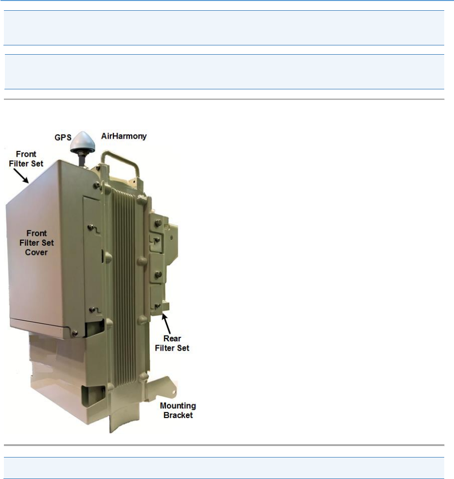
Figure 2: AirHarmony-4400 with Front & Rear Filter Sets & cover
Note: External Filters set are sold separately and are installed on site by the customer.
AirHarmony-4400 (External Cavity Filters) Installation Guide
UGD-D01186 Airspan Commercial and Internal Use 17
2 Getting Started
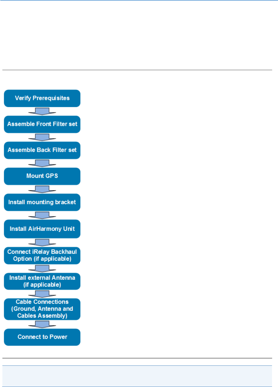
2.1 Workflow of Installation
The Workflow to install the AirHarmony-4400 is displayed in the following diagram:
Figure 3: Workflow
Caution: Antennas and External filters must be connected and attached before AirHarmony-4400 is
powered on.
AirHarmony-4400 (External Cavity Filters) Installation Guide
UGD-D01186 Airspan Commercial and Internal Use 18
2.2 AirHarmony-4400 Installation Checklist
Plan the installation of the AirHarmony-4400 by using the Installation Checklist, which you can find
as a removable job aid in Appendix A for this guide.
3 Verifying Prerequisites
Prior to installing the AirHarmony-4400, verify the required safety, power, tools, parts and
components. This chapter includes the hardware, software, and client requirements for installation.
Important: Set up requirements for the installation is detailed in the Job Sheet, see Appendix_A.
3.1 Verifying Site Requirements
To set up the AirHarmony-4400, an IP connection to a Netspan server is required.
3.2 Verify Installation Requirements
3.2.1 Verify the Tools
Table 7. Minimum Hardware Requirements
Tool
Use
Medium Phillips head screw driver
for securing the M5 Pan Head screws on Filter sets
#13 wrench
for securing the M8 Hex Head bolts on the
Pole/wall mount
Small flat blade screw driver (insulated
shaft recommended)
For AC power cable preparation
pliers
For AC power cable preparation
Knife
For AC cable preparation
Small side cutters
For AC power cable preparation
Wire strippers
For AC power cable preparation
1/2” Socket Wrench
For 5/16” Hex head (Lag) bolts when wall mounting
AirHarmony-4400 (External Cavity Filters) Installation Guide
UGD-D01186 Airspan Commercial and Internal Use 19
3.2.2 Verify the Parts and Kits
Note: Verify your order and requirements to ensure the correct unit type is being installed.
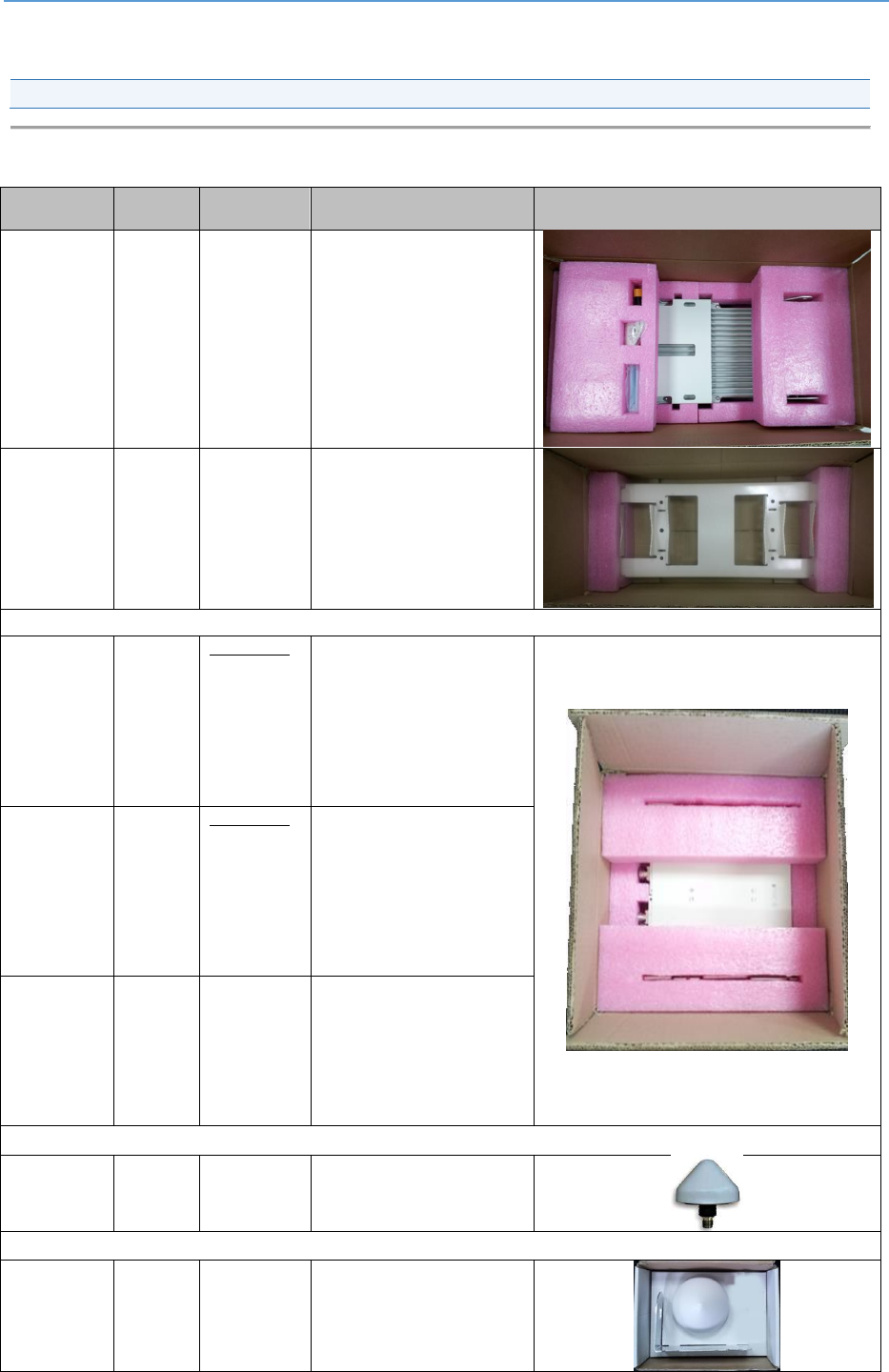
Table 8. Parts & Kits
Installation
Kit / Part
Part No.
Airspan
N0.
Consisting of:
Image
AirHarmony
4400 2500M
Hz (B41)
HAR44-
EF-U41-
B06AP
998-43-
413SP
AirHarmony 4400 2.496 -
2.69 GHz (B41, B38), External
Filters (not included),
Connectorized 2x Fiber + 2x
Copper, PoE, AC
AirHarmony
4400
universal
wall & pole
mounting kit
HAR40-
U-PMK-1
903-03-257
Pole/wall mount bracket
Screws for connecting
the unit
External Filters Sets
Harmony440
0 External
filters set
B41 Low
Band
HAR44-
FLTR-KIT-
U41L
903-03-264
AirHarmony 4400 External
filters set B41 Low Band
U41-Low External IP67
Single Cavity Filter 2496-
2568MHz, DIN 4.1/9.5(f)
connectors X4
Filter set mounting with
screws
Harmony440
0 External
filters set
B41 High
Band
HAR44-
FLTR-KIT-
U41H
903-03-266
AirHarmony 4400 External
filters set B41 High Band
U41-High Single External
IP67 Cavity Filter 2618-
2690MHz, DIN(f)4.1/9.5
connectors X4
Filter set mounting with
screws
Harmony440
0 External
filters set
B41 Full
Band
HAR44-
FLTR-KIT-
U41F
903-03-265
AirHarmony4400 External
filters set B41 Full Band
Filter,Cavity,2496-
2690MHz,External,SMP
connector X4
Filter set mounting with
screws
GPS Antenna
GPS Antenna
GPS-
ANT-3
350-05-009
GPS Antenna with built-in
high, interference rejection
Or
GPS Antenna
Kit
GPS-
HAR-KIT-
1
N/A
AirHarmony GPS Kit
(including antenna, bracket,
80cm cable and surge
protection kit)
AirHarmony-4400 (External Cavity Filters) Installation Guide
UGD-D01186 Airspan Commercial and Internal Use 20
Installation
Kit / Part
Part No.
Airspan
N0.
Consisting of:
Image
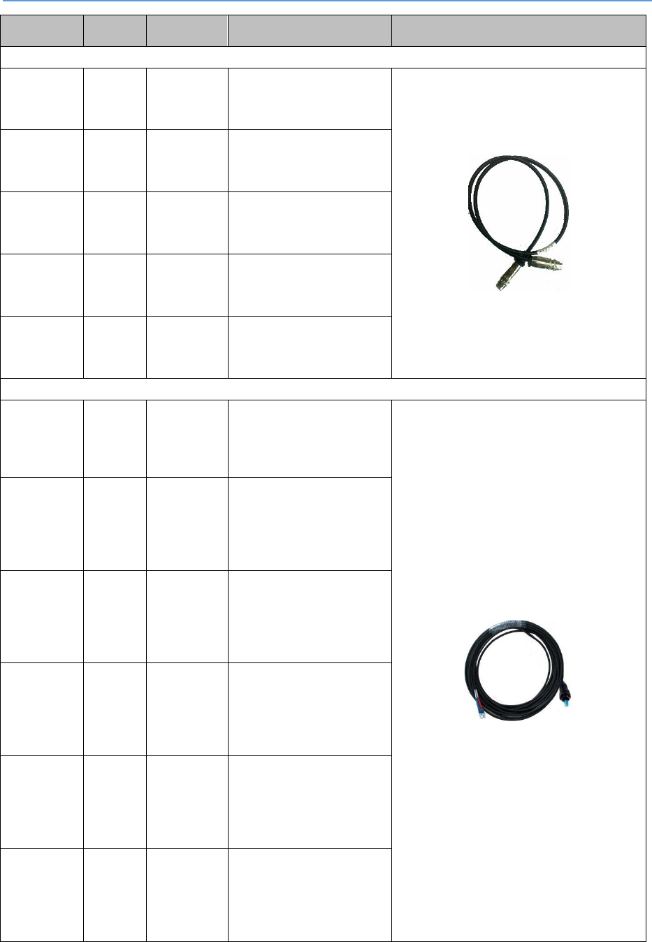
LSBA Control Cable
Long SBA
control cable
AISG to AISG
1.5m
CBL-
SBAL-
CTRL-
1.5-1
680-00-191
Long SBA
control cable
AISG to AISG
3m
CBL-
SBAL-
CTRL-3-1
680-00-192
Long SBA
control cable
AISG to AISG
5m
CBL-
SBAL-
CTRL-5-1
680-00-193
Long SBA
control cable
AISG to AISG
10m
CBL-
SBAL-
CTRL-10-
1
680-00-194
Long SBA
control cable
AISG to AISG
16m
CBL-
SBAL-
CTRL-16-
1
680-00-195
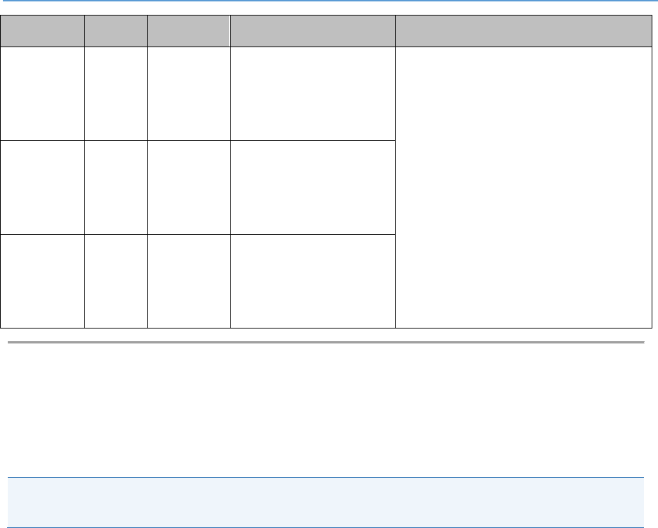
Full AXS SM Fiber Cable
Full AXS SM
Fiber Cable
5m, Outdoor
LC/DPX to
LC, IP67
FIB-FA-5-
LC-SM-1
686-00-016
Full AXS SM
Fiber Cable
7.5m,
Outdoor
LC/DPX to
LC, IP67
FIB-FA-
7.5-LC-
SM-1
686-00-017
Full AXS SM
Fiber Cable
15m,
Outdoor
LC/DPX to
LC, IP67
FIB-FA-
15-LC-
SM-1
686-00-015
Full AXS SM
Fiber Cable
30m,
Outdoor
LC/DPX to
LC, IP67
FIB-FA-
30-LC-
SM-1
686-00-009
Full AXS SM
Fiber Cable
50m,
Outdoor
LC/DPX to
LC, IP67
FIB-FA-
50-LC-
SM-1
686-00-010
Full AXS SM
Fiber Cable
75m,
Outdoor
LC/DPX to
LC, IP67
FIB-FA-
75-LC-
SM-1
686-00-011
AirHarmony-4400 (External Cavity Filters) Installation Guide
UGD-D01186 Airspan Commercial and Internal Use 21
Installation
Kit / Part
Part No.
Airspan
N0.
Consisting of:
Image
Full AXS SM
Fiber Cable
100m,
Outdoor
LC/DPX to
LC, IP67
FIB-FA-
100-LC-
SM-1
686-00-012
Full AXS SM
Fiber Cable
150m,
Outdoor
LC/DPX to
LC, IP67
FIB-FA-
150-LC-
SM-1
686-00-013
Full AXS SM
Fiber Cable
200m,
Outdoor
LC/DPX to
LC, IP67
FIB-FA-
200-LC-
SM-1
686-00-014
3.2.3 Power Supply and Current
AirHarmony-4400 supports direct connection to AC power source:
Operational Voltage Range: 100VAC~240VAC, 47Hz~63Hz
Warning: Power provided by PoE outputs (RJ45 ETH1, ETH2) cannot be considered limited power
source (LPS) per IEC/UL 60950-1 clause 2.5
AirHarmony-4400 (External Cavity Filters) Installation Guide
UGD-D01186 Airspan Commercial and Internal Use 22
Table 9. Amperage Draw
Duplex
Tx Power at RF Port (dBm)
Maximum Power Consumption (W)
TDD-FC1
2 x 43
340
FDD
2 x 43
340
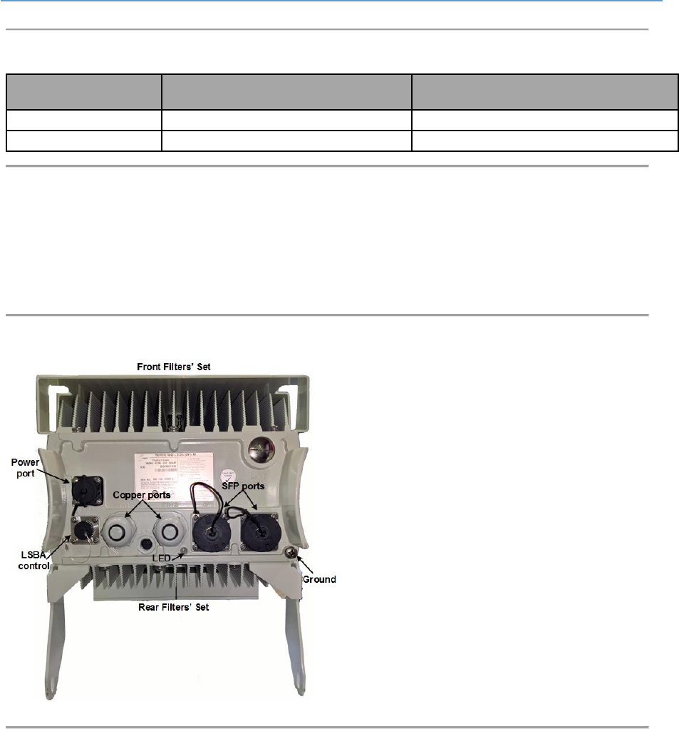
3.2.4 Panels
The following figures display the AirHarmony-4400 bottom and top panels.
The following displays the AirHarmony-4400’s bottom panel.
Figure 4: AirHarmony-4400 Unit, Bottom panel
AirHarmony-4400 (External Cavity Filters) Installation Guide
UGD-D01186 Airspan Commercial and Internal Use 23
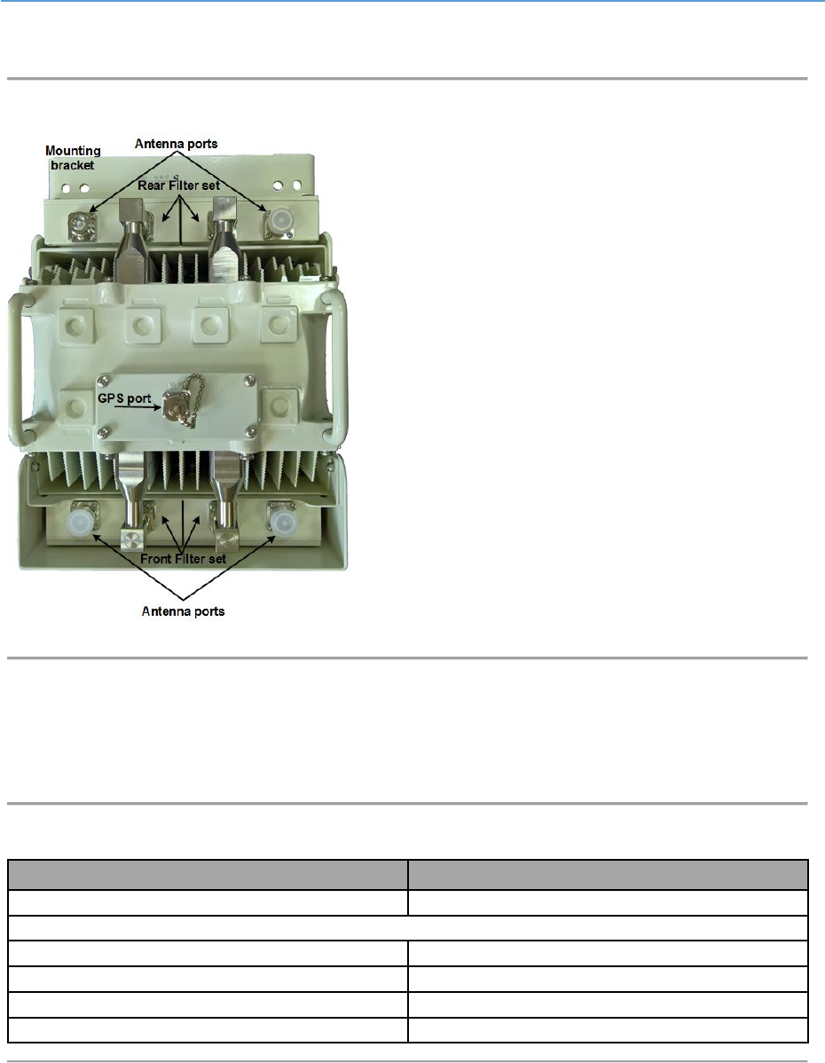
The following displays the AirHarmony-4400’s top panel.
Figure 5: AirHarmony-4400 Unit, Top panel
3.2.5 Physical Dimensions
AirHarmony-4400 is in an all outdoor enclosure.
Table 10: AirHarmony-4400 Physical Dimensions
Variant
Dimensions (H x W x D)
AirHarmony-4400
509 x 262 x 252 mm / 20.0 x 10.3 x 9.9 inch
Weight
Main Unit (without filter sets)
19.6 Kg / 43.21 Lbs.
Main Unit (with filter sets)
26 Kg / 57.32 Lbs.
Universal mounting bracket
3 Kg / 6.6 Lbs.
Quadruple Filter Set – Band 41
6 Kg / 13.2 Lbs.
AirHarmony-4400 (External Cavity Filters) Installation Guide
UGD-D01186 Airspan Commercial and Internal Use 24
3.2.6 Environmental
AirHarmony-4400 meets the following environmental requirements:
GR-63 Storage and Transportation
ETSI EN 300-019-1-4 Operational (non-weather protected equipment)
ETSI EN 300-019-1-1 Storage (weather protected, non-temperature controlled locations)
ETSI EN 300-019-1-2 Transportation
Table 11: AirHarmony-4400 Environment Compliance
Type
Details
Standard Compliance
Operating temperature
-40°C to 55°C / -40°F to 131°F
ETSI 300 019 1-4
Operating humidity
5% - 100% non-condensing
ETSI 300 019 1-4
Storage temperature
-40°C to 70°C
N/A
Storage humidity
5% - 100% non-condensing
ETSI 300 019 1-4
Rain and dust ingress
protection
IP66
N/A
Operational altitude
70-106 kPa as well as:
From -60m to 1800m @ 40C
From 1800m to 4400m @ 30C
ETSI 300 019 1-4
Solar radiation
1120 W/m2
ETSI 300 019 1-4
AirHarmony-4400 (External Cavity Filters) Installation Guide
UGD-D01186 Airspan Commercial and Internal Use 25
4 Installing AirHarmony-4400
Install the AirHarmony-4400 eNodeB by pole/wall mount. AirHarmony-4400 is mounted on a pole or
wall in close proximity to its external antenna (connectorized variant).
Caution: Proper local rigging and hoisting practices should be followed when installing
the AirHarmony-4400 on pole or wall.
4.1 Rear External Filter Set Assembly
Note: Both External Filters’ sets should be assembled on the AirHarmony-4400 prior to
installing on the pole/wall mount. Airspan recommends doing the assembly on a steady
secure surface.
1. Remove the upper polyethylene packing foam and set aside for later use.
2. Carefully remove the AirHarmony unit from the packaging and stand on end.
Caution: Make sure that the AirHarmony unit is standing securely.
3. Remove the lower polyethylene packing foam and set down.
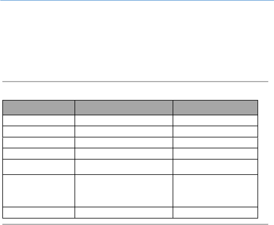
4. Lie the AirHarmony unit down in the horizontal position on packing foam so as to
facilitate assembly of the rear external filters’ set (either Low, High or Full Band).
Figure 6: AIrHarmony-4400 - in Horizontal Position prior to Rear External Filters Set Assembly
5. Open the Filters Sets packaging and carefully remove both the front and rear filter sets.
6. Set the rear external filters’ set aside in preparation for assembly.
Note: Verify that the required External Filters set are used as there are three (3):
AirHarmony 4400 Band 41 Low Filter 2496 - 2568 MHz – with a White label
AirHarmony 4400 Band 41 High Filter 2618 - 2690 MHz – with a Black label
AirHarmony 4400 Band 41 Full Range Filter 2496 - 2690 MHz – with a Silver label
AirHarmony-4400 (External Cavity Filters) Installation Guide
UGD-D01186 Airspan Commercial and Internal Use 26
Figure 7: Rear External Filters' Set
Note: The Rear External Filters’ Set come assembled with the M5 pan head screws
holding the external filters in place on the filter bridge.
7. Align the four screw slots in order to fit the rear external filters’ set in place.
8. Position the rear external filters’ set on the AirHarmony-4400 in position so the slots on
the sides align with the M5 pan head screws on the unit’s back plate.
9. Insert all four (4) M5 screws (supplied) and tighten with screwdriver.
Figure 8: Mounting Rear External Filters' set
10. Loosen the eight (8) M5 screws on the filters to allow easy alignment of with RF
connector.
11. Align the back bracket (over the rear filter set) and once aligned insert the supplied
M8x20 Hex head bolt with a split washer and a flat washer into each clinch-nut.
AirHarmony-4400 (External Cavity Filters) Installation Guide
UGD-D01186 Airspan Commercial and Internal Use 27
Figure 9: Back Bracket Assembly
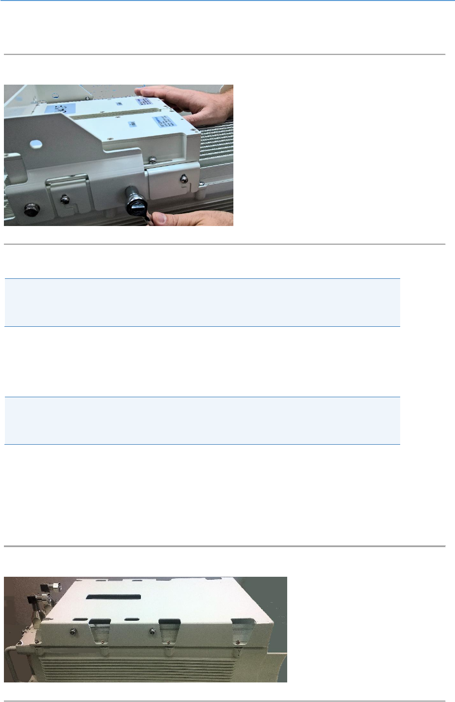
12. Slide the filter to align it with its RF connector and fit together, then tighten the
connector.
Figure 10: Fitting RF Connector
Caution: Take care not to over tighten the RF connector. The connector nut should be
tightened to a nominal torque of no more than 15 [N*m] (11.06 lb-ft). Using either 22
mm or 7/8” open end torque wrench.
13. After tightening both RF connectors, proceed to tighten the eight (8) M5 screws on the
filters
Figure 11. Tighten the Filter Screws
AirHarmony-4400 (External Cavity Filters) Installation Guide
UGD-D01186 Airspan Commercial and Internal Use 28
14. Next tighten the four (4) M8X20 Hex head bolts which fasten the filter to the filter
bridge bracket.
Figure 12: Tighten Hex Head Bolts
Airspan recommends weather-proofing the RF connections.
Note: Weather-proofing of all the connections is recommended. This is done with a layer
of self-amalgamating tape followed by an over layer of PVC tape. The weather-proofing
is best done at this stage to give easier access to the connections.
Proceed to assemble the front external filter set.
4.2 Front External Filter Set Assembly
Note: Both External Filters’ sets should be assembled on the AirHarmony-4400 prior to
installing on the pole/wall mount. Airspan recommends doing the assembly on a steady
secure surface.
1. Turn the unit over in preparation for the Front External Filters’ set assembly and lie the
AirHarmony-4400 down on a flat surface so as to facilitate assembly of the front external
filters’ set (either Low, High or Full Band).
2. Place part of the polyethylene packing foam under the unit so as to protect the
AirHarmony from getting any scratches.
Figure 13: AIrHarmony-4400 in Prone Position Prior to Front External Filter Assembly
AirHarmony-4400 (External Cavity Filters) Installation Guide
UGD-D01186 Airspan Commercial and Internal Use 29
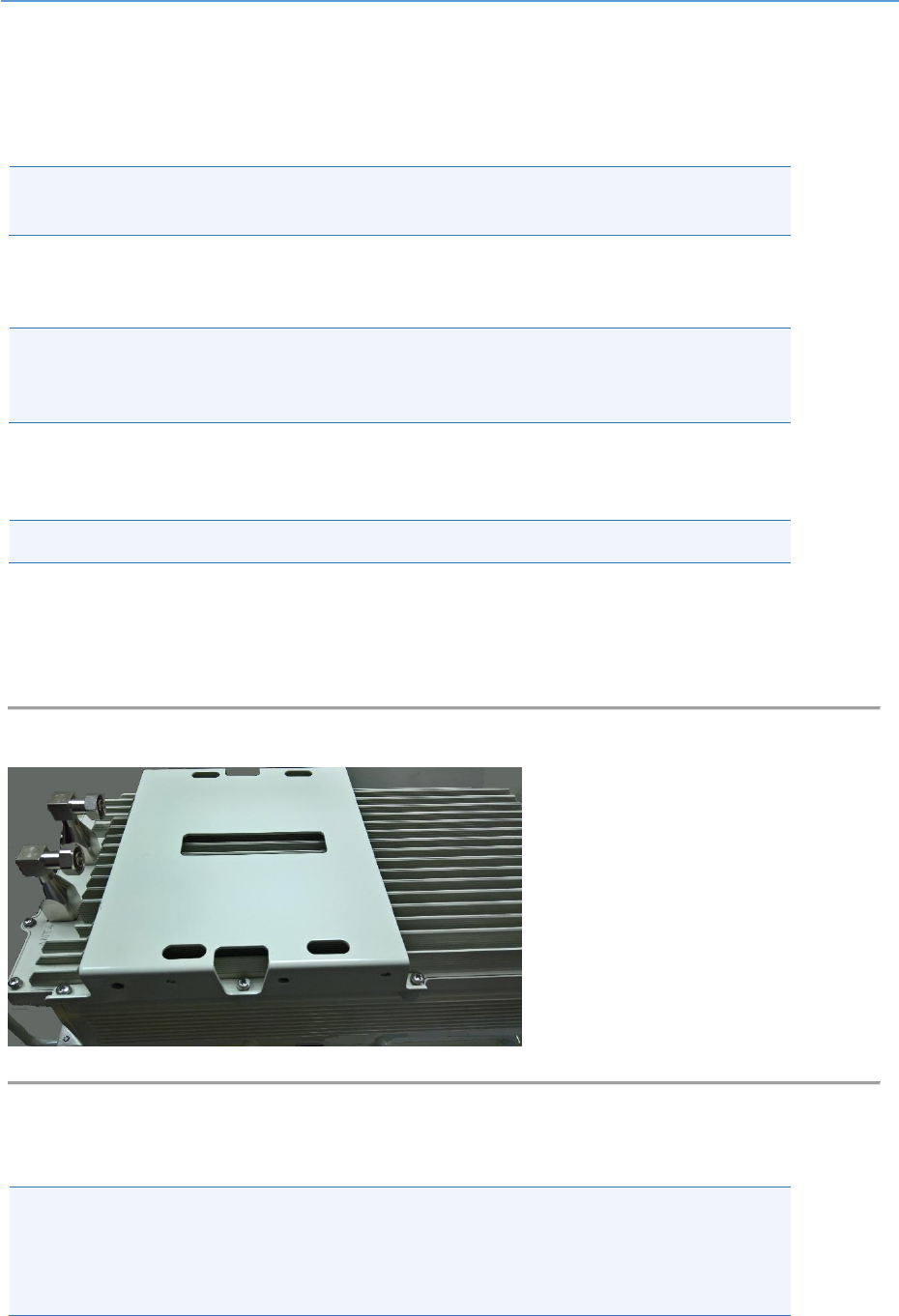
3. Take the front external filters’ set in preparation for assembly.
Note: Verify that the required External Filters set are used as there are three (3):
AirHarmony 4400 Band 41 Low Filter 2496 - 2568 MHz – with a White label
AirHarmony 4400 Band 41 High Filter 2618 - 2690 MHz – with a Black label
AirHarmony 4400 Band 41 Full Range Filter 2496 - 2690 MHz – with a Silver label
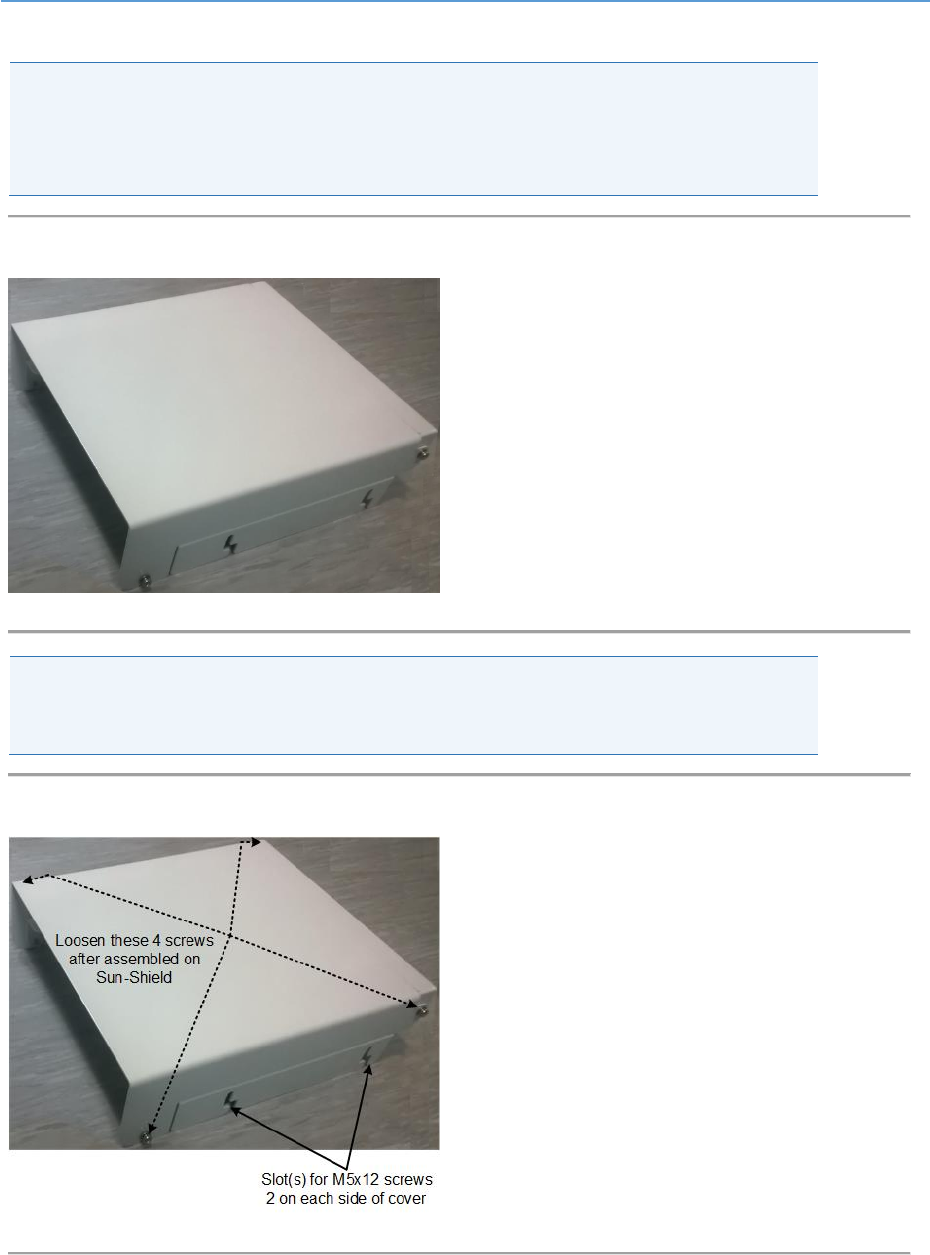
Figure 14: External Filters' Set
Note: The External Filters’ Set come assembled with the M5 pan head screws holding the
external filters in place on the Filter bridge and M5 pan head screws holding the cover
on the filter bridge.
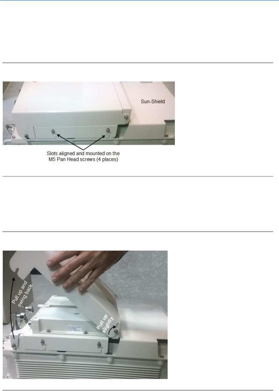
Figure 15: External Filters' Set slots & fastenings
AirHarmony-4400 (External Cavity Filters) Installation Guide
UGD-D01186 Airspan Commercial and Internal Use 30
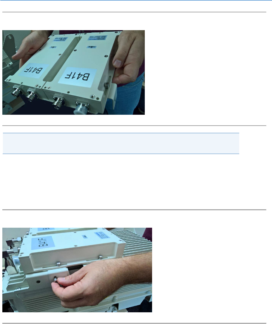
4. Loosen the four (4) M5 screws on the Sun-Shield in order to fit the External Filters’ set in
place.
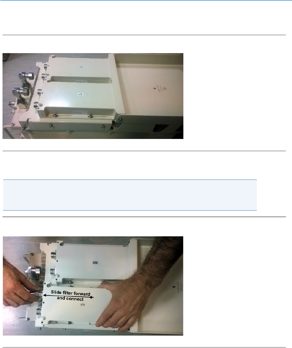
5. Position the External Filters’ set on the AirHarmony-4400 in position on the Sun-Shield
so the slots on the sides align with the M5 pan head screws projecting from the Sun-
Shield.
Figure 16: Mounting External Filters' set on Sun-shield
6. Loosen the four (4) M5 screws on the filter cover that lock the filter cover in place on the
External Filters’ set.
7. Pull up slightly on the filter cover bottom (to release the cover a bit) and pull the cover
up and back to open the cover.
Figure 17: Opening cover
AirHarmony-4400 (External Cavity Filters) Installation Guide
UGD-D01186 Airspan Commercial and Internal Use 31
8. Pull outward on the filter cover to pull it free and swing the filter cover down away from
the cavity filters and open the cover completely.
Figure 18. Cover opened
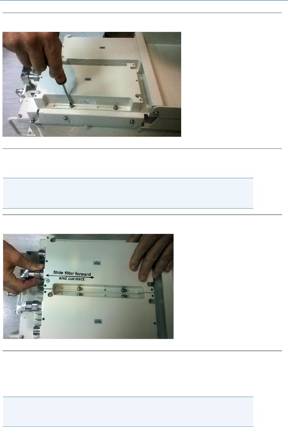
9. Slide the filter to align it with its RF connector and fit together, then tighten the
connector.
Caution: Take care not to over tighten the RF connector. The connector nut should be
tightened to a nominal torque of no more than 15 [N*m] (11.06 lb-ft). Using either
22mm or 7/8” open end torque wrench.
Figure 19: Align and fit filter to connector
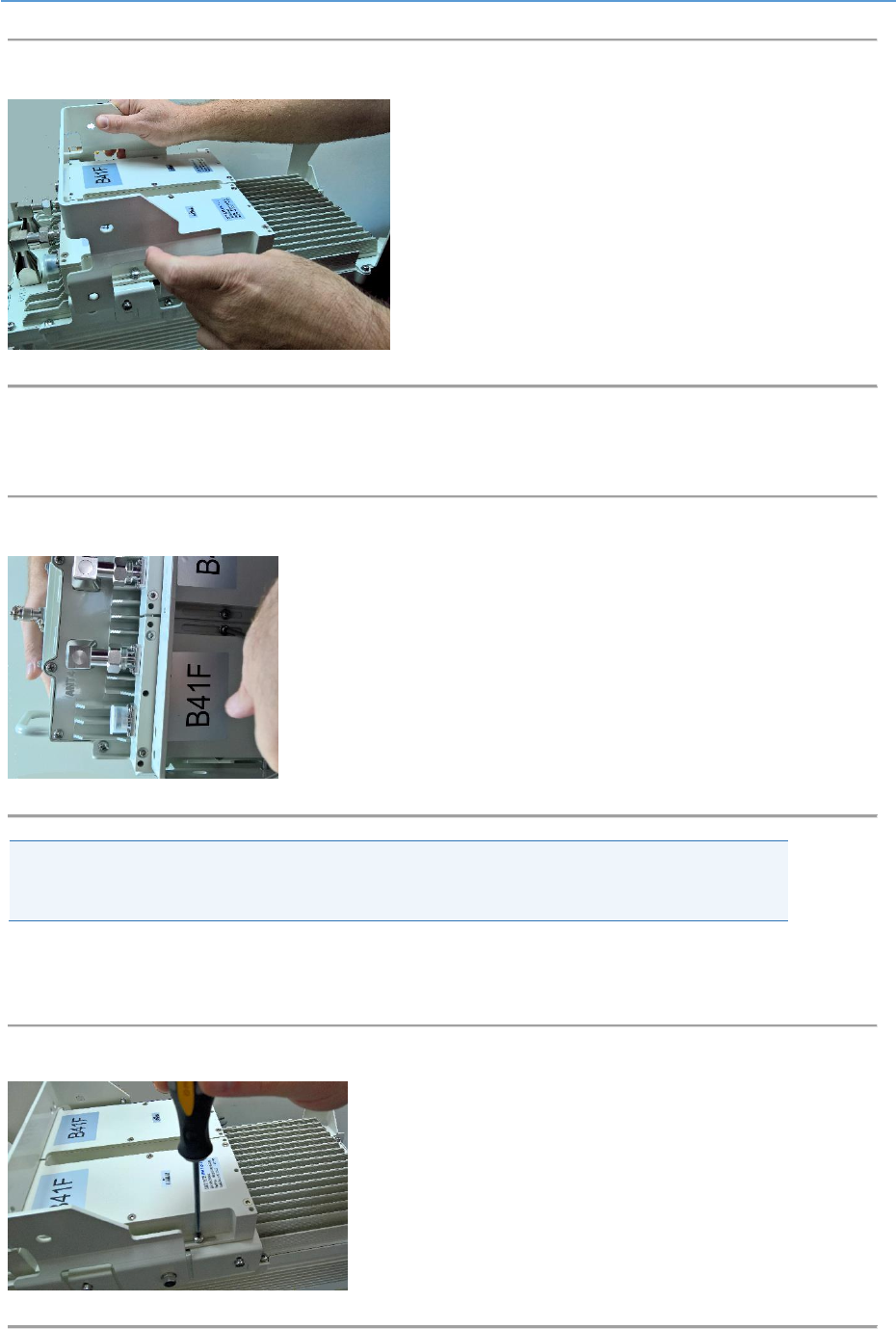
10. Next tighten the four (4) screws which fasten the filter to the filter bridge.
AirHarmony-4400 (External Cavity Filters) Installation Guide
UGD-D01186 Airspan Commercial and Internal Use 32
Figure 20: Tighten screws on filter
11. Slide the second filter to align it with its RF connector and fit together, then tighten the
connector.
Caution: Take care not to over tighten the RF connector. The connector nut should be
tightened to a nominal torque of no more than 15 [N*m] (11.06 lb-ft). Using either
22mm or 7/8” open end torque wrench.
Figure 21: Align and fit second filter to connector
12. Tighten the four (4) screws which fasten the second filter to the filter bridge.
13. Tighten the four (4) screws which fasten the filter bridge to the Sun-Shield.
Airspan recommends weather-proofing the RF connections.
Note: Weather-proofing of all the connections is recommended. This is done with a layer
of self-amalgamating tape followed by an over layer of PVC tape. The weather-proofing
is best done at this stage to give easier access to the connections.
AirHarmony-4400 (External Cavity Filters) Installation Guide
UGD-D01186 Airspan Commercial and Internal Use 33
Figure 22: Tighten filter bridge screws on Sun-Shield
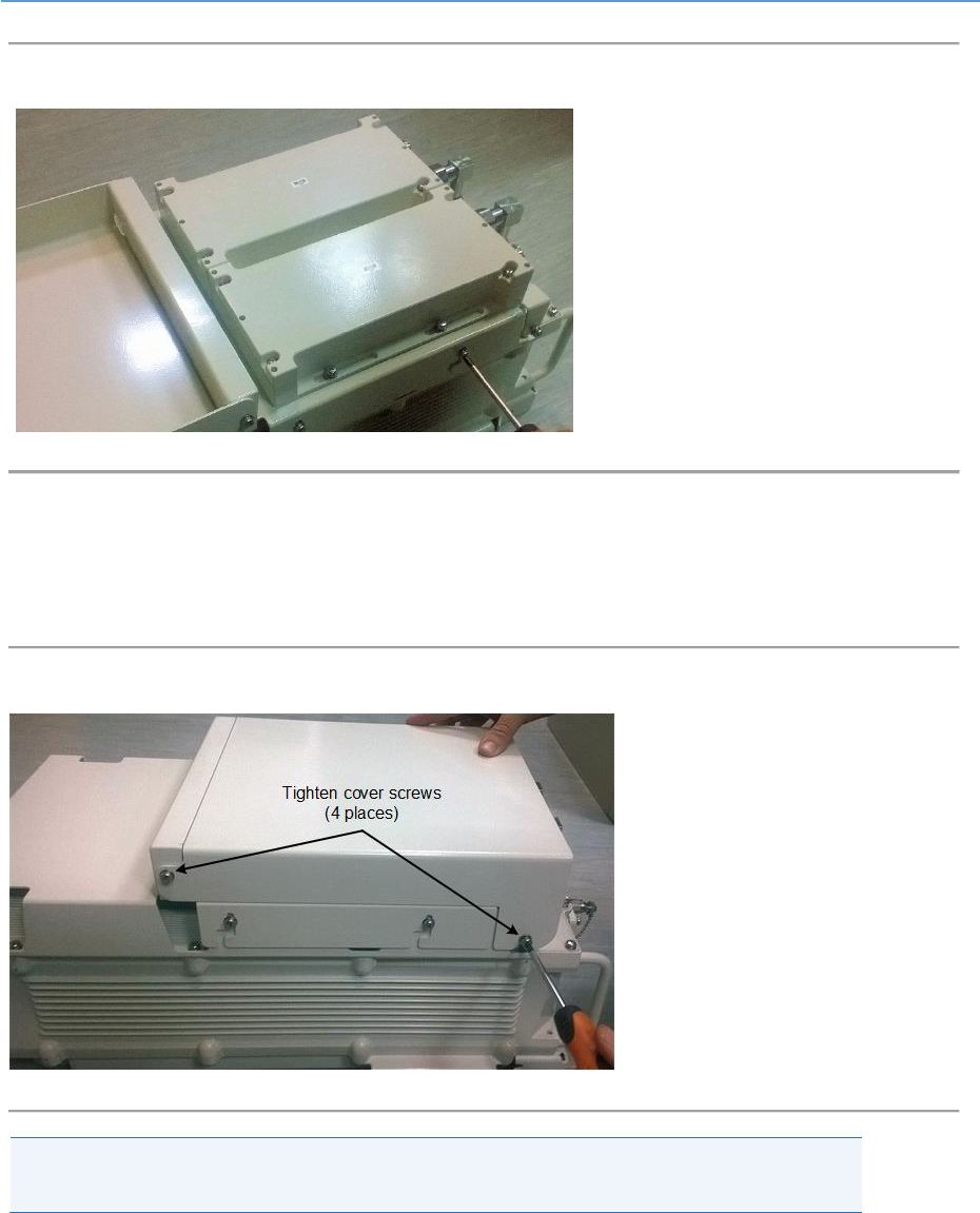
14. Swing the filters’ cover up till slots are aligned with the two (2) upper bolts on the filter
bridge.
15. Once in place tighten all four (4) screws to lock the filters’ cover in place.
Figure 23: Tighten screws on cover
Note: The changing or replacing of the external filter sets will require a dismantling of
the AirHarmony 4400 from its mounting position to perform this change or replacement.
4.3 Connecting the GPS Antenna
After assembly of the External Filters set, the GPS antenna should be connected and it is
recommended that the connection should be weather-proofed.
The following describes the connection of the GPS antenna which is installed directly to the top of
the unit.

AirHarmony-4400 (External Cavity Filters) Installation Guide
UGD-D01186 Airspan Commercial and Internal Use 34
1. Unscrew the protective dust cap from the GPS antenna jack prior to mounting on the
AirHarmony-4400.
2. Align the GPS jack with the plug attached to the top panel on the AirHarmony-4400.
Figure 24: Attaching GPS antenna to unit
Caution: Take care not to over tighten so as not to damage the threads.
Note: It is good practice to weather-proof all the antenna connections. This is done with
a layer of self-amalgamating tape followed by an over layer of PVC tape. The weather-
proofing the GPS connection is best done at this stage to give easier access to the
connections.
AirHarmony-4400 (External Cavity Filters) Installation Guide
UGD-D01186 Airspan Commercial and Internal Use 35
4.4 Pole/Wall Mount Assembly
Install the AirHarmony-4400 eNodeB by pole/wall mount. AirHarmony-4400 is mounted on a pole or
wall in close proximity to its external antenna (connectorized variant).
Caution: Proper local rigging and hoisting practices should be followed when installing
the AirHarmony-4400.
4.4.1 Mounting on a Wooden Pole
The following images show the pole mount assembly on a wooden pole.
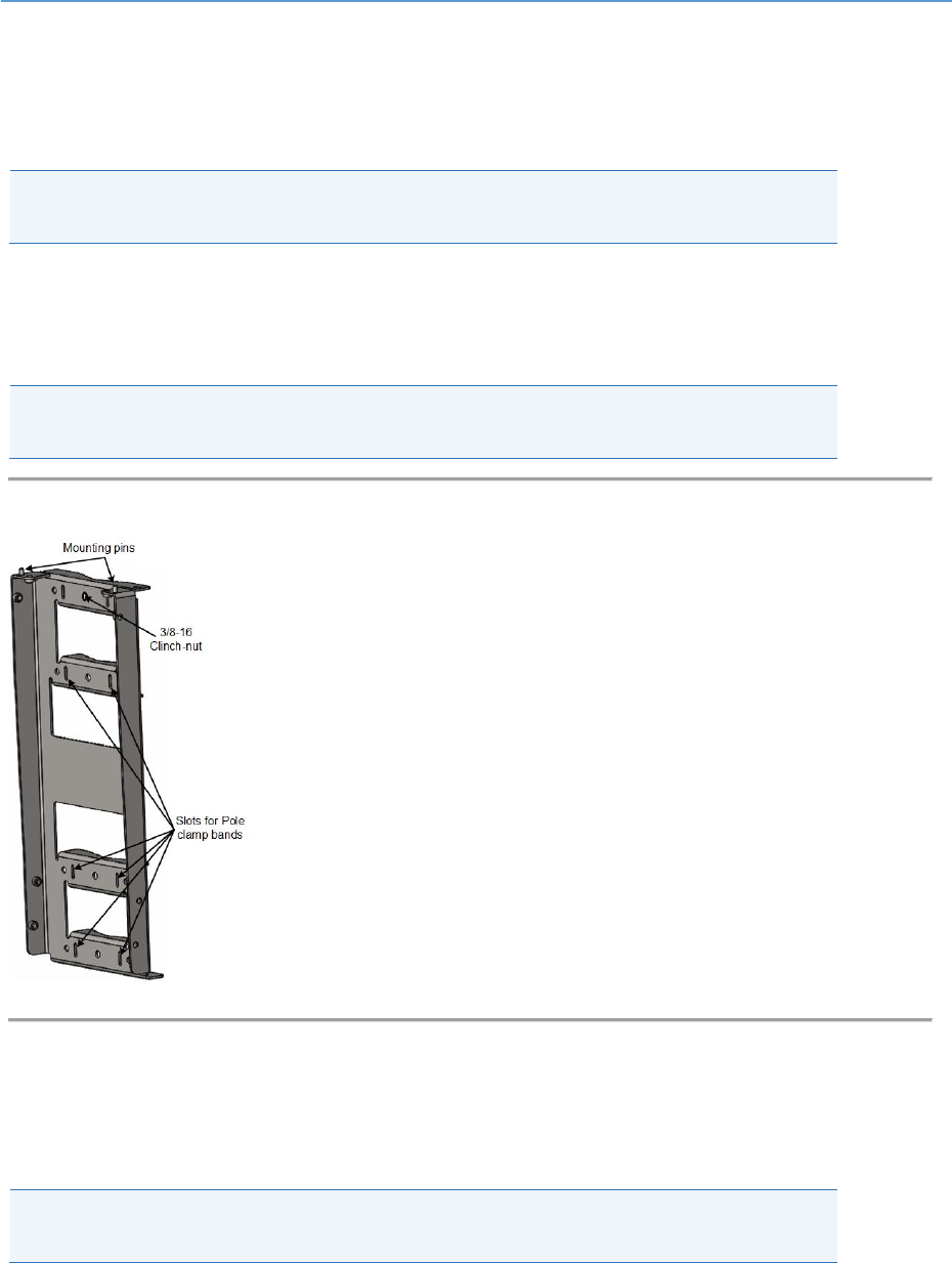
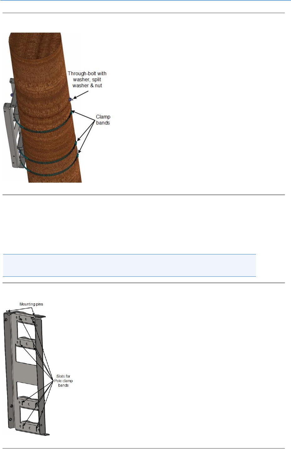
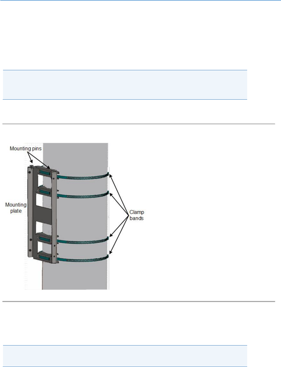
Caution: Take care to install the Pole/Wall mounting plate in the correct orientation.
Verify that the mounting pins are facing upwards as shown below.
Figure 25: Pole/Wall mounting plate
1. Select the location on the pole to mount the AirHarmony-4400. You can attach the
AirHarmony-4400 to any pole from 1-7/8 to 16 inches (47.6 to 406.4 mm) in diameter.
2. Determine where to position the mounting plate on the pole and mark where to drill for
insertion of the 3/8-16 through-bolt.
Note: Threaded rod and necessary hardware are not supplied by Airspan and are the
responsibility of the installer.
AirHarmony-4400 (External Cavity Filters) Installation Guide
UGD-D01186 Airspan Commercial and Internal Use 36
3. Drill a minimum 7/16” hole to accept the 3/8-16 threaded rod.
4. Thread the 3/8-16 threaded rod into the provided clinch-nut attached on the Pole/Wall
mounting plate.
5. Holding the mounting plate (with the attached threaded rod) pass the 3/8-16 threaded rod
through the drilled hole in the pole.
6. Install on the exposed thread that protrudes from pole a flat washer, split washer, and
then a 3/8”-16 hex nut and tighten.
7. Insert the clamp bands by passing them through the slots in the mounting plate, in three
(3) places.
Note: The clamp bands are not supplied by Airspan and are the responsibility of the
installer. Clamp bands should not be wider than 15.5 mm in order to fit in the slots on
the mounting plate.
8. Tighten the clamp bands with large flat screwdriver.
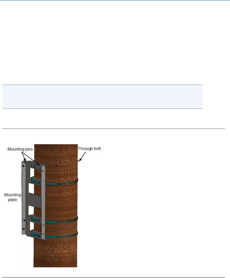
Figure 26: Mounting plate on pole
AirHarmony-4400 (External Cavity Filters) Installation Guide
UGD-D01186 Airspan Commercial and Internal Use 37
Figure 27: Through-bolt & Mounting plate
Mounting plate is installed and ready for AirHarmony-4400 mounting.
4.4.2 Mounting on a Non-Wooden Pole
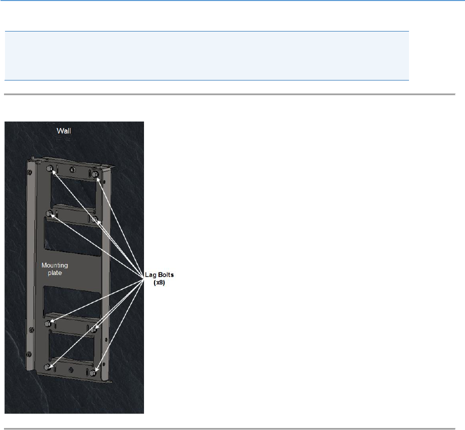
The following images show the pole mount assembly on a non-wooden pole.
Caution: Take care to install the Pole/Wall mounting plate in the correct orientation.
Verify that the mounting pins are facing upwards as shown below.
Figure 28: Pole/Wall mounting plate (w/o bolt)
AirHarmony-4400 (External Cavity Filters) Installation Guide
UGD-D01186 Airspan Commercial and Internal Use 38
1. Select the location on the pole to mount the AirHarmony-4400. You can attach the
AirHarmony-4400 to any pole from 1-7/8 to 16 inches (47.6 to 406.4 mm) in diameter.
2. Insert the clamp straps through the slots in the mounting plate passing them through
the pole clamps.
3. Insert the clamp bands by passing them through the slots in the mounting plate, in four
(4) places.
Note: The clamp bands are not supplied by Airspan and are the responsibility of the
installer. Clamp bands should not be wider than 15.5 mm in order to fit in the slots on
the mounting plate.
4. Tighten the clamp bands with large flat screwdriver.
Figure 29: Mounting plate mounted
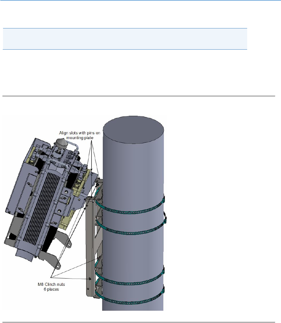
4.4.3 Mounting on a Wall
The following images show the wall mount assembly.
Caution: Take care to install the Pole/Wall mounting plate in the correct orientation.
Verify that the mounting pins are facing upwards as shown below.
1. Position mounting plate against the wall with mounting pins facing up. Be sure to
position the wall mounting plate straight with level mounting to ensure the unit sits
evenly.
2. Mark the wall through the holes on the wall mount at the required height.
AirHarmony-4400 (External Cavity Filters) Installation Guide
UGD-D01186 Airspan Commercial and Internal Use 39
3. Attach the mounting plate to the wall using Lag bolts (x8 recommended).
Note: Lag bolts (x8) and necessary hardware are not supplied by Airspan and are the
responsibility of the installer. Recommended minimum 5/16 x 4” dia. (8mm x 100mm)
with appropriate plugs according to field conditions.
Figure 30: Mounting Plate on Wall
AirHarmony-4400 (External Cavity Filters) Installation Guide
UGD-D01186 Airspan Commercial and Internal Use 40
4.5 Securing AirHarmony-4400 to the Mounting Plate
Caution: Proper local rigging and hoisting practices should be followed when installing
the AirHarmony-4400 on pole or wall.
To mount AirHarmony-4400 to the mounting plate, perform the following:
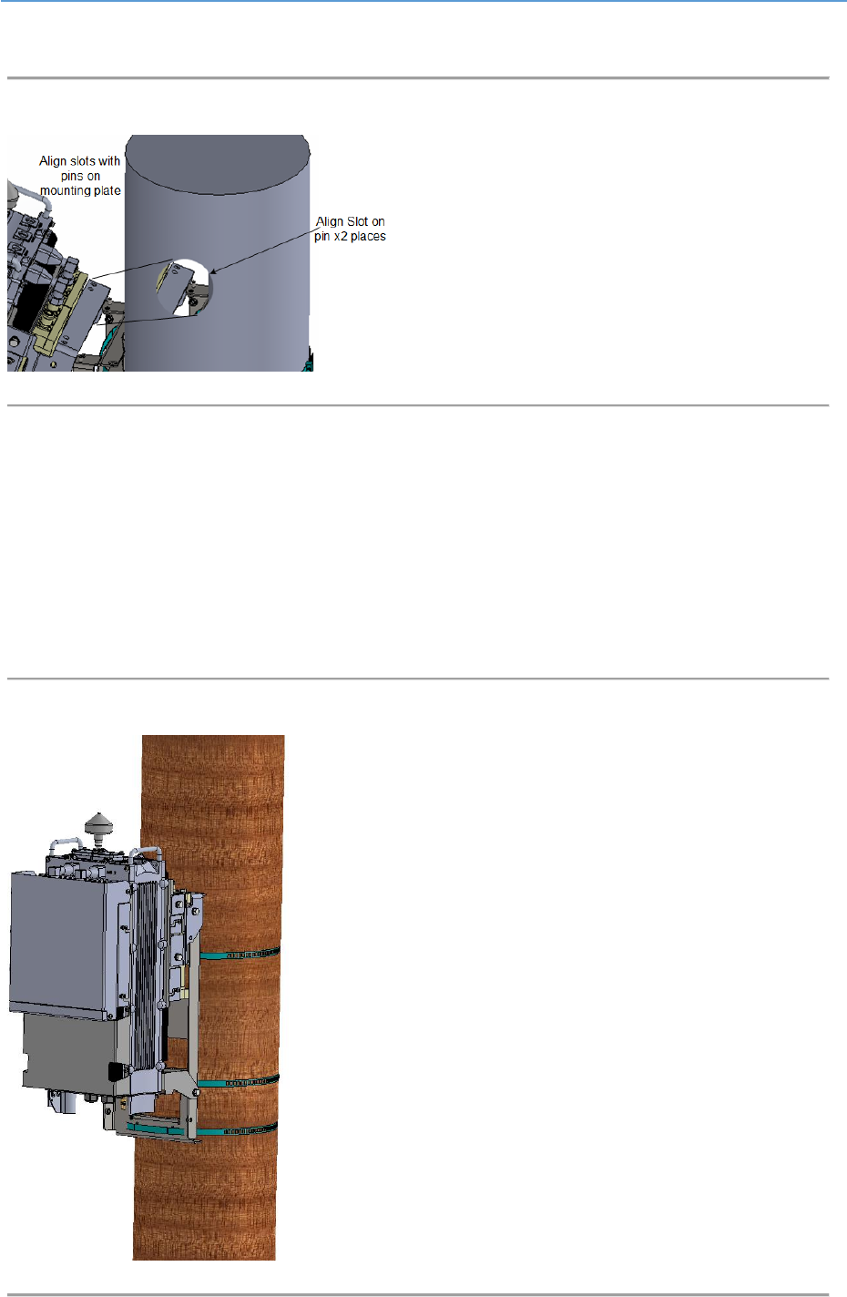
1. Lift up the AirHarmony-4400 unit and hook the slotted holes onto the mounting pins
(studs) on the top of the mounting plate.
Figure 31: Lift unit and fit the slotted holes unto studs on top of mounting plate
AirHarmony-4400 (External Cavity Filters) Installation Guide
UGD-D01186 Airspan Commercial and Internal Use 41
The following displays a close up of the Pin (stud) alignment.
Figure 32: Align Pins
2. Lean the bottom of the unit into the mounting plate until the six (6) holes are aligned
with the six (6) M8 clinch-nuts on the mounting plate. There are two (2) on the top, near
the mounting pins and two (2) on either side of the mounting plate for a total of six (6) .
3. Once aligned insert the supplied M8x20 Hex head bolt with a split washer and a flat
washer into each clinch-nut.
4. Check and tighten all six (6) M8x20 Hex head bolts.
The following displays the AirHarmony-4400 mounted on a wooden pole.
Figure 33: AirHarmony mounted on Wooden Pole
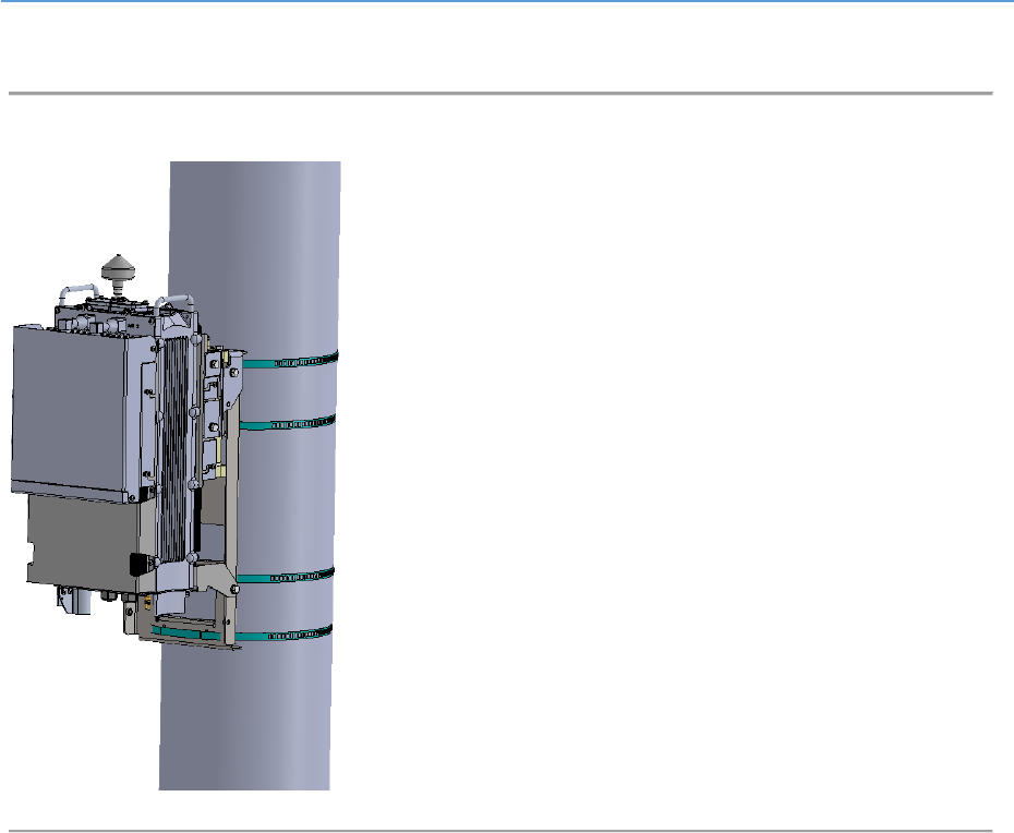
AirHarmony-4400 (External Cavity Filters) Installation Guide
UGD-D01186 Airspan Commercial and Internal Use 42
The following displays the AirHarmony-4400 mounted on a concrete pole.
Figure 34: AirHarmony mounted on Concrete Pole
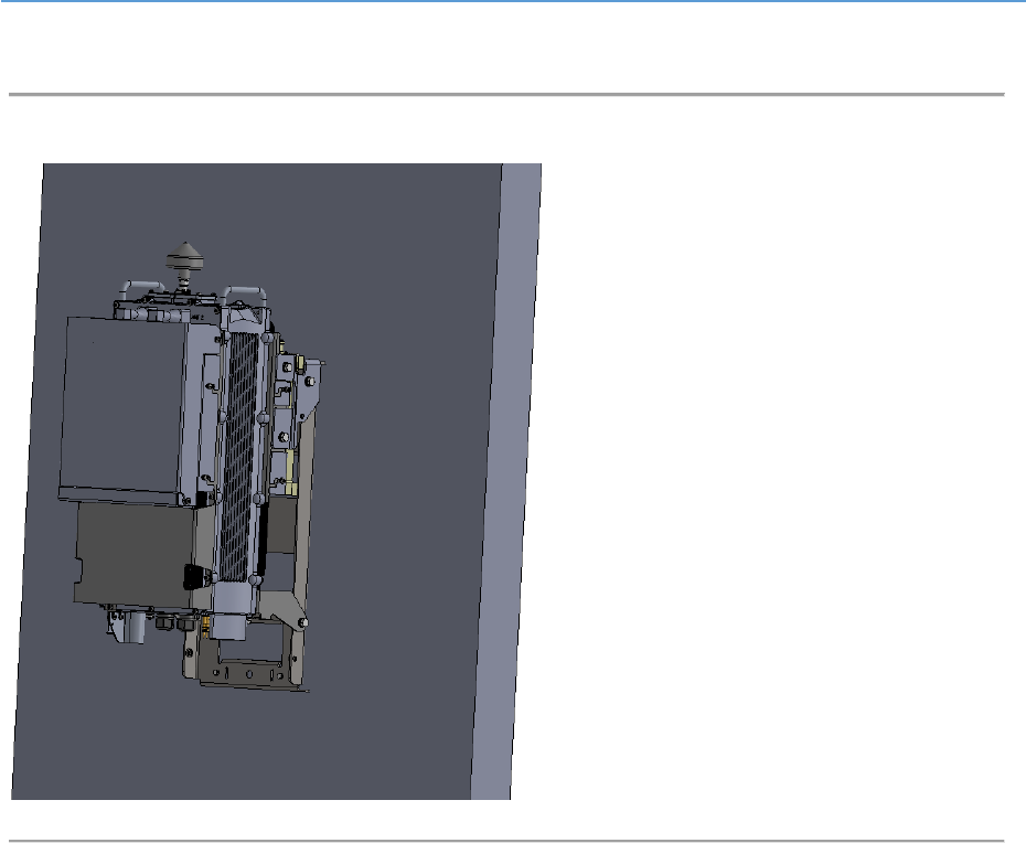
AirHarmony-4400 (External Cavity Filters) Installation Guide
UGD-D01186 Airspan Commercial and Internal Use 43
The following displays the AirHarmony-4400 being mounted on a wall.
Figure 35: AirHarmony being mounted on a Wall
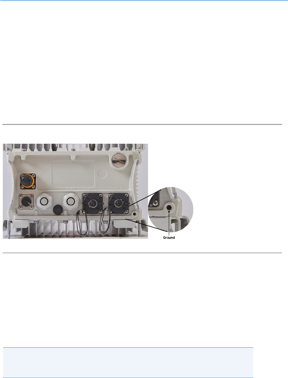
AirHarmony-4400 (External Cavity Filters) Installation Guide
UGD-D01186 Airspan Commercial and Internal Use 44
5 AirHarmony-4400 Connections
This section describes Grounding procedure, cable preparation and connections and external
antenna assembly.
5.1 Grounding
The AirHarmony-4400 requires a secure ground connection. The ground cable should be connected
with the grounding screw (M6x16) fitted with a flat washer and lock washer (supplied) to the bottom
of the chassis clearly marked with the universal ground symbol as shown below. The grounding
screw (M6 x 16) is pre-installed during assembly.
Figure 36: Grounding
The cable should be grounded and bonded according to international or local standards.
5.2 Remote Antenna Assembly
The AirHarmony-4400 unit is be used with a remotely attached antenna.
For installation of a remotely mounted antenna follow the antenna manufacturer’s instructions and
connect the antenna to the AirHarmony-4400 external filter RF connectors (female DIN 4.1/9.5
connector) using the appropriate cables with a male DIN 4.1/9.5 connector.
Caution: Take care not over tighten the RF connector. The connector nut should be
tightened to a nominal torque of no more than 10.0 Nm (1.47 lb-ft). RF failures can
result when the RF connector is over-tightened.
5.2.1 Connecting RF Jumper Cables to External Antenna
The following describes how to connect the antenna cables to the cavity filters.
1. Attach, connect and secure the RF cables, with a DIN 4.1/9.5 connector(s) (Male -
internal thread) coming from the external antenna and the two (2) RF connections on
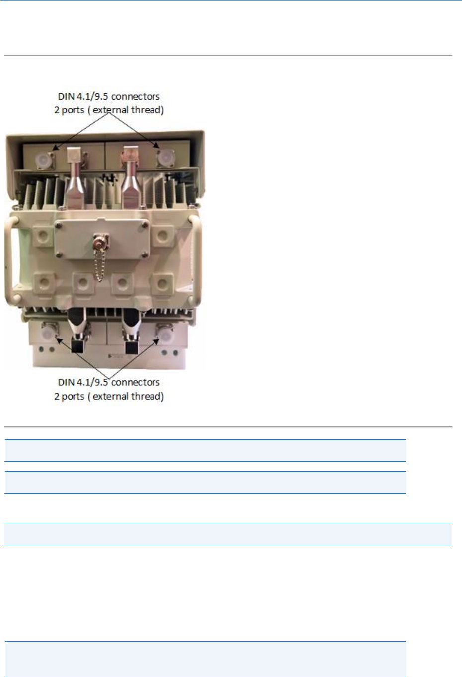
AirHarmony-4400 (External Cavity Filters) Installation Guide
UGD-D01186 Airspan Commercial and Internal Use 45
the filter, which has two (2) ports with DIN 4.1/9.5 connectors (Female - external thread)
on the top of the cavity filter.
Figure 37: DIN 4.1/9.5 connectors (external thread)
Caution: Antennas must be connected and attached before AirHarmony is powered on.
Caution: Power down AirHarmony prior to disconnecting antenna.
2. Weather-proof the RF connections.
Note: The above is also applicable for replacement assembly.
5.2.2 Weather-proofing the Antenna Connections
Weather-proofing of all the connections is required. This is done with a layer of self-amalgamating
tape followed by an over layer of PVC tape. The weather-proofing is best done at this stage to give
easier access to the connections.
Note: Weather-proofing is best done at the assembly stage to give easier access to the
connections. Weather-proofing is to be done to all RF connectors.
Verify the RF connectors are completely weather-proof.
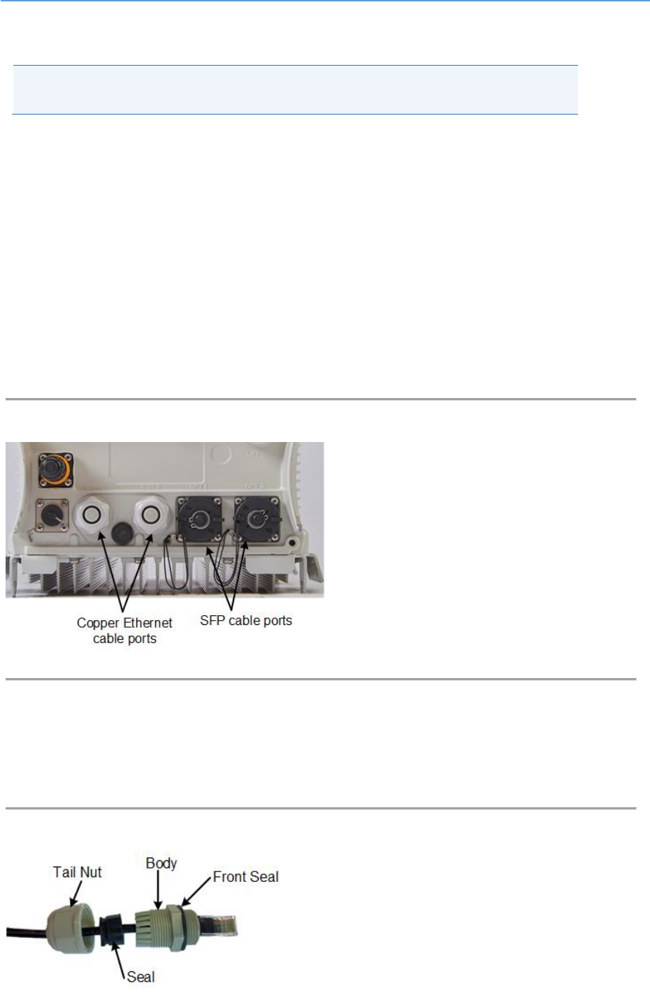
AirHarmony-4400 (External Cavity Filters) Installation Guide
UGD-D01186 Airspan Commercial and Internal Use 46
5.3 Cable Connections
Note: The following images are for illustration purposes only. The actual tools or
hardware may differ according to manufacturer.
5.3.1 Copper Ethernet Cable Assembly
The following demonstrates the recommended assembly instructions, hardware and tool
requirements for the proper Ethernet cable assembly of the Ethernet Category 5e (enhanced)
(CAT5e) cable used by Airspan products.
The Ethernet cable is connected using a standard RJ45 connector protected by a harsh environment
protective casing.
Assembly Instructions
The Copper Ethernet cable is connected to the AirHarmony-1000 using a Gland connector assembled
on the bottom panel of the unit, as shown below.
Figure 38: Gland connector - copper
1. Remove the Gland connector by unscrewing the body from the AirHarmony-1000, using
the (supplied) Gland wrench.
2. Pass the prepared Ethernet cable through the tail nut, gland seal, body and front seal of
the connector casing as shown below. Do not tighten the tail nut.
Figure 39: Ethernet Cable through connector
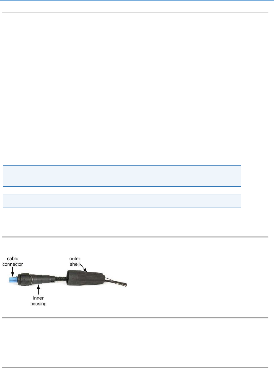
AirHarmony-4400 (External Cavity Filters) Installation Guide
UGD-D01186 Airspan Commercial and Internal Use 47
3. Seat the RJ45 connector plug securely into the body cavity of the AirHarmony-4400
4. Tighten the Gland body into to the threaded hole on the bottom of the AirHarmony-
4400.
5. Tighten the tail nut on to the body using the included Gland wrench, forcing the seal
compress around the cable.
6. Once the connector is properly installed, the cable should be positioned and secured to
minimize stress on the cable.
5.4 Fiber Ethernet (SFP) Cable Installation
The Fiber Ethernet Small form-factor pluggable transceiver (SFP) must be connected to the
AirHarmony -4400 using an outdoor fiber cable. The optical connection enables a one-hand
installation of the connector. This enables the users to easily remove and replace the SFP transceiver
module which eliminates the need to open the unit and expose its contents to hazardous weather
conditions. use only SFP which are safety approved IEC 60825 and CDRH with class 1 laser
Note: Airspan recommends using the Finisar - FTLF1318P3BTL 1000BASE-LX which has
been tested and approved by Airspan. Available from Airspan if required.
Note: Use only SFP which are safety approved IEC 60825 and CDRH with class 1 laser.
5.4.1 SFP Cable Connection
Figure 40: LC duplex cable assembly
1. Remove the protective dust cap from the connector housing assembled on the unit.
2. Line up the SFP transceiver module with the port and slide it into the port.
3. Connect the cable connector onto the board connector.
Figure 41: Cable connector hook up to the board connector
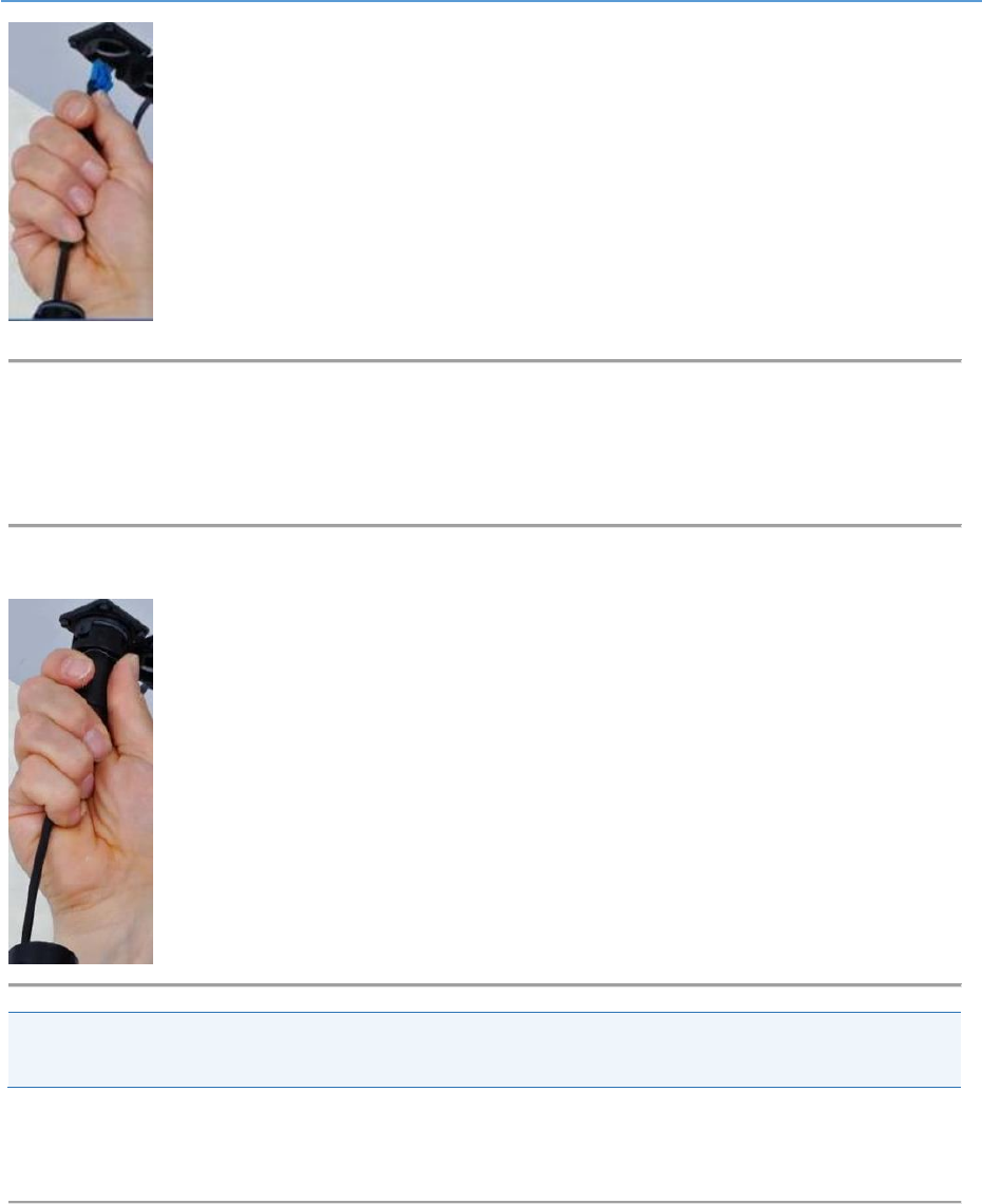
AirHarmony-4400 (External Cavity Filters) Installation Guide
UGD-D01186 Airspan Commercial and Internal Use 48
4. Verify that the locking latch on the cable connector is engaged on the board connector.
5. Slide the inner housing and ground shield (if present) over the cable and over the
molding.
Figure 42: Slide on inner housing
Note: Check that there no space between the inner housing and mounting flange. Check and
remove any debris that might interfere with the connection.
6. Slide the outer shell over the inner housing and turn the outer bayonet shell 1/4 turn
clockwise, until it clicks into place.
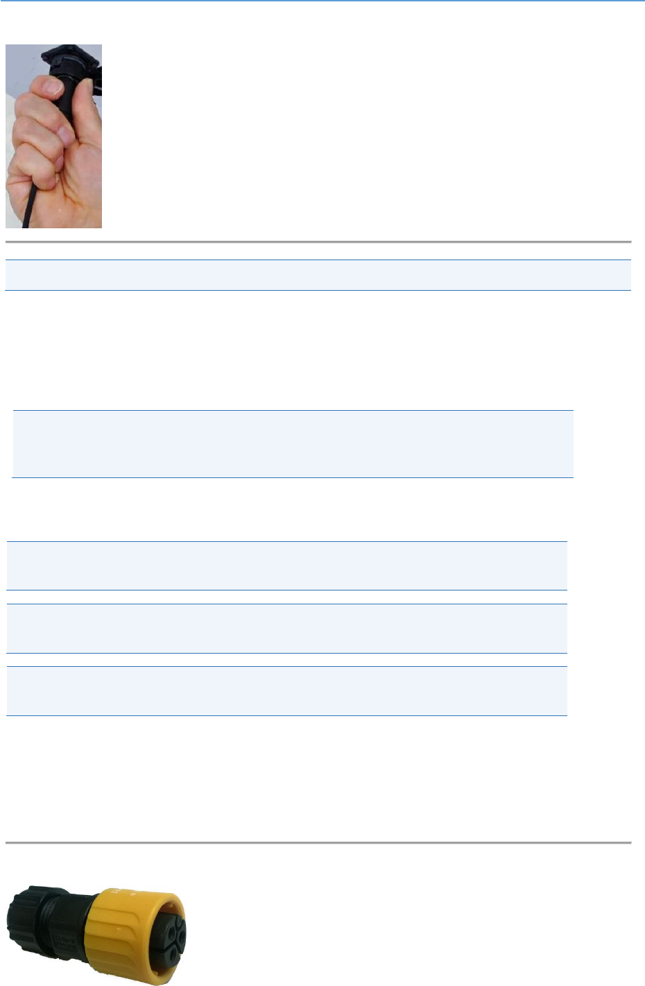
AirHarmony-4400 (External Cavity Filters) Installation Guide
UGD-D01186 Airspan Commercial and Internal Use 49
Figure 43: Slide over and click
Note: The shell should be hand tightened only. Do NOT use tools to tighten the shell.
Once the connector is properly installed, the cable should be positioned and secured to minimize
stress on the cable and connector.
5.5 Connecting the AC Power Cable to AirHarmony-4400
Danger: Hazardous voltage! Before working, ensure that the power is removed from the
power connection cables. When the system is powered on, do not touch the power
terminals.
5.5.1 Power Cable Preparation
Tip: It is good practice to label both ends of the cable to identify which AirHarmony-4400
unit it is connected to.
Tip: It is good practice to leave a spare loop of cable (approximately 0.5m). This will allow
for easier wiring and will allow the cable to be re-terminated if necessary in the future.
Warning: Required - circuit breaker for AC power source -16A for EU installation and 20A
for US installation. Minimum – 10A.
The power cable is connected to the AirHarmony-4400 connector (marked PWR) on the bottom
panel of the unit.
1. Prepare the connector by unscrewing the body pf the AC connector, included in the
AirHarmony-4400 package.
Figure 44: AC connector
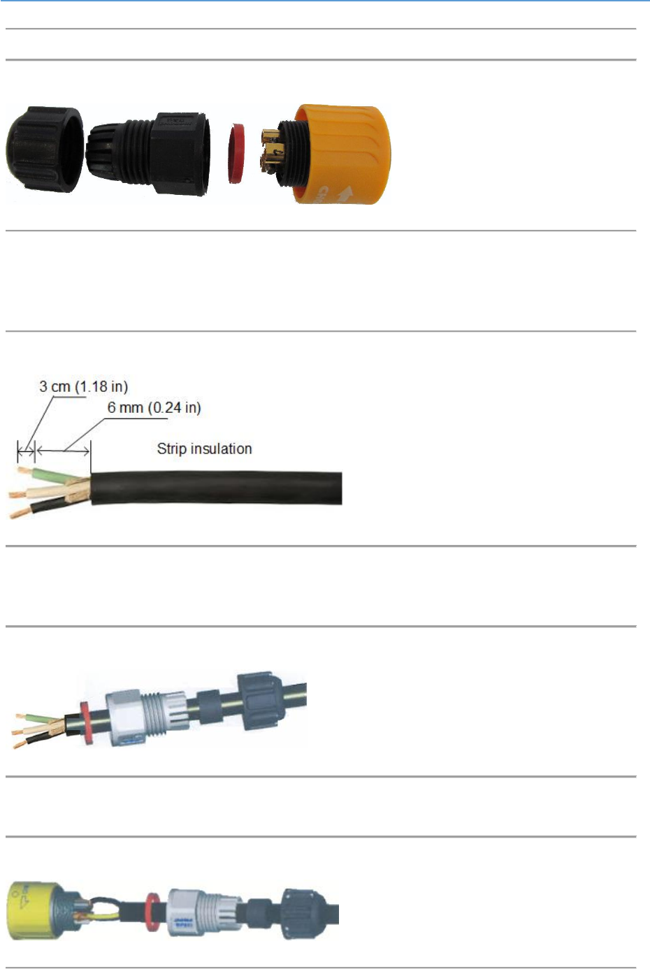
AirHarmony-4400 (External Cavity Filters) Installation Guide
UGD-D01186 Airspan Commercial and Internal Use 50
Figure 45: AC Connector disassembled
2. Strip back and remove the outer sheath to expose the inner black, white and green
insulated wires to a length of 3 cm (1.18 in). Then strip back 6 mm (0.24 in) of the inner
core insulation.
Figure 46: Strip wire
3. Thread the 3 wire (stranded 18AWG) cable through the tail nut, gland seal, body and
rubber gasket of the connector casing as shown below. Do not tighten the tail nut.
Figure 47: power cable assembly
4. Insert the stripped wire ends of the cable into the connector sleeves.
Figure 48: Connector on cable
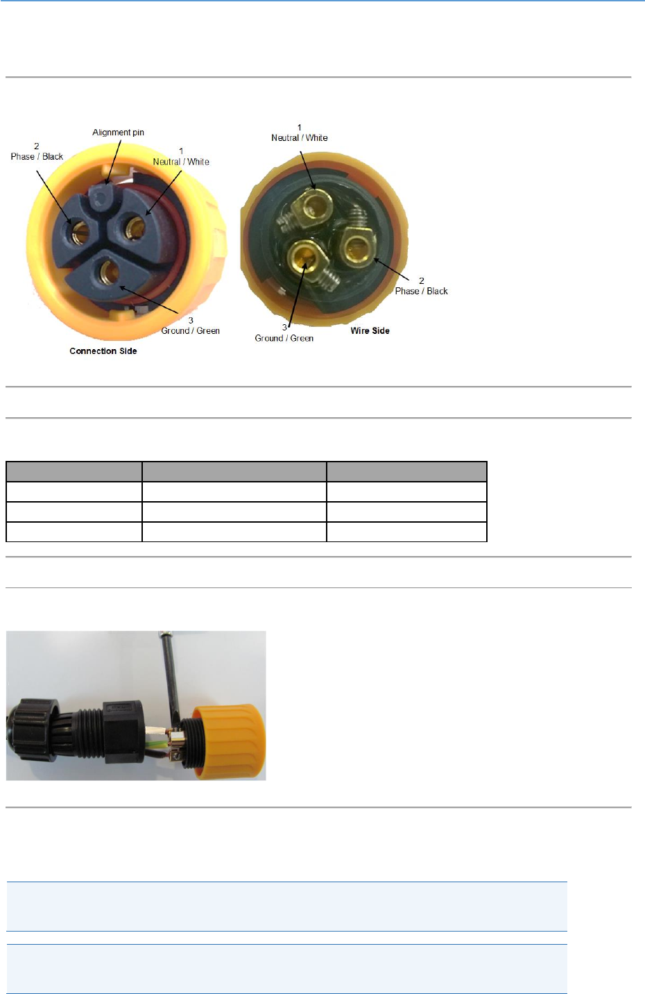
AirHarmony-4400 (External Cavity Filters) Installation Guide
UGD-D01186 Airspan Commercial and Internal Use 51
5. Secure the wire ends of the power cable into the head part of the connector, as shown
below.
Figure 49: Plug pins
Figure 50: Pin assignment
Pin #
Wire Color
Description
1
White
Neutral
2
Black
Phase
3
Green
Ground
Figure 51: Attaching wires
6. Insert into connector, the by alignment pin determines the correct orientation.
7. Tighten the tail nut on to the body forcing the seal to compress around the power cable.
Caution: Do not over tighten the connector or the tail nut. The nut should be tightened
to a torque of no more than 3.3 Nm (2.43 lb-ft) max.
Note: When securing the cable verify there is no tension on the connector so that it is
easy to disconnect and re-connect for future maintenance actions.
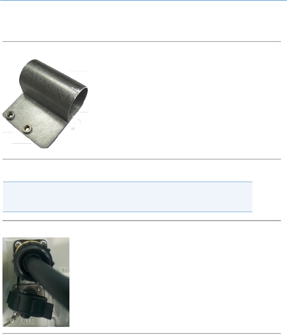
AirHarmony-4400 (External Cavity Filters) Installation Guide
UGD-D01186 Airspan Commercial and Internal Use 52
8. Remove the connector’s protective cap on the bottom panel of the unit.
9. Slide the Connecter Clamp over the connector housing prior to connecting.
Figure 52: Connector Clamp
10. Tighten the assembled power cable to the connector.
Caution: The internal plastic parts of the mating connector are keyed. Take care to align
these by visual inspection or by gently rotating the connector body until the key way
sections align and the pins engaged fully before tightening.
Figure 53: Power cable attached to AirHarmony-4400
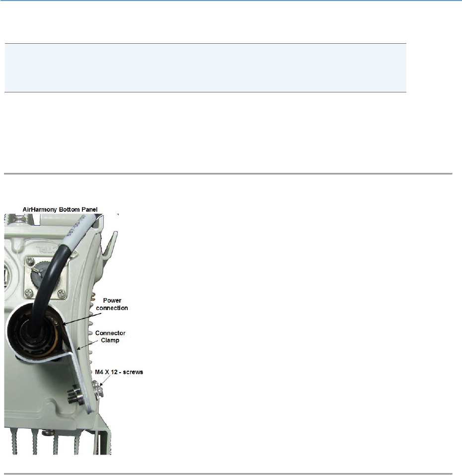
AirHarmony-4400 (External Cavity Filters) Installation Guide
UGD-D01186 Airspan Commercial and Internal Use 53
5.5.2 Securing Connector Clamp
Warning: Required – For safety reasons it is imperative to secure the power cable with
the Connector clamp after connection. This is to prevent manually disconnecting the
power cable.
After the power cable is connected securing the connection is required.
1. This is performed by inserting the 2 – M4 x 12 screws into the provided holes and
tightening the screws. The clamp covers the connector and prevents access to the
connection so it cannot be opened without difficulty.
Figure 54: Securing the connection

AirHarmony-4400 (External Cavity Filters) Installation Guide
UGD-D01186 Airspan Commercial and Internal Use 54
A Job Sheet
This job sheet enables the users to keep track of their installation. It covers all the prerequisites
required for accomplishing the AirHarmony-4400 installation.
Table 12: Job Sheet
Site Requirements
Pole or wall for installation identified
Position on pole or wall identified
Pole access restrictions (highway regulations, other services on pole, power pole)
Method of reaching pole positions (ladders, Elevated work platform)
AC main fuse block available for AC/DC converter (where needed)
Configuration programming details known
Point of connection for Ethernet (if applicable)
All equipment items available at the installation site:
● Main AirHarmony-4400 unit
● External Filter Set – verify required set
● GPS Antenna
● Mounting bracket, through-bolt and pole clamps, or bolts if wall mount
● Copper Ethernet or SFP cable assembly
● Weather-proofing of the connections with a layer of self-amalgamating tape
followed by an over layer of PVC tape.
Tool Requirements
(For further information, see Verify the Tools.)
Large flat screw driver
Small flat blade screw driver (insulated shaft recommended)
Medium Philips head screw driver
13 mm wrench
Knife
pliers
Small side cutters
Wire strippers
Required Ancillary Equipment
Laptop PC for initial configuration
Cable for temporary connection of the laptop
Other installed materials
Cable ties
Labels (good to have)

AirHarmony-4400 (External Cavity Filters) Installation Guide
UGD-D01186 Airspan Commercial and Internal Use 55
B Abbreviations
Term
Expansion
3GPP
3rd Generation Partnership Project, responsible for LTE
ABS
Almost Blank Subframes
ACS
Adjacent Channel Selectivity is a measurement of a receiver's ability to process a desired
signal while rejecting a strong signal in an adjacent frequency channel. ACS is defined as the
ratio of the receiver filter attenuation on the assigned channel frequency to the receiver
filter attenuation on the adjacent channel frequency.
AWGN
Additive White Gaussian Noise is a channel model in which the only impairment to
communication is a linear addition of white noise with a constant spectral density and a
Gaussian distribution of amplitude.
BER
Bit Error Rate
CN
Core Network
CP
Cyclic Prefix
CTC
Convolution Turbo Code is a high-performance forward error correction (FEC) code
dB
Decibel. A logarithmic unit used to describe a ratio (such as power ratio in radio
telecommunications)
dBm
An abbreviation for the power ratio in decibels (dB) of the measured power referenced to
one milliwatt (mW). It is used as a convenient measure of absolute power because of its
capability to express both very large and very small values in a short form.
eNodeB
Evolved Node B, is the element in E-UTRAN of LTE.
ESP
Encapsulating Security Payloads (ESP) provide confidentiality, data-origin authentication,
connectionless integrity, an anti-replay service (a form of partial sequence integrity), and
limited traffic-flow confidentiality
E-UTRAN
Evolved UMTS Terrestrial Radio Access Network, is the air interface of 3GPP's Long Term
Evolution.
EVM/RCE
The Error Vector Magnitude or EVM (sometimes also called Receive Constellation Error or
RCE) is a measure used to quantify the performance of a digital radio transmitter or receiver.
It is measured in dB or percentage (%) – the lower the better.
FDD
Frequency-Division Duplexing. A transceiver mode where the transmitter and receiver
operate at different carrier frequencies.
GNSS
Global Navigation Satellite System is a term used to describe a satellite navigation system
with global coverage. There are currently two fully operational GNSSs – the US GPS and the
Russian GLONASS
GTP-U
GPRS Tunneling Protocol for User data is a relatively simple IP based tunneling protocol
which permits many tunnels between each set of end points
HPBW
Half Power BandWidth is the angular separation in an antenna, in which the magnitude of
the radiation pattern decreases by 50% (or -3 dB) from the peak of the main beam
ICS
In-channel selectivity is a measure of the receiver’s ability to receive a wanted signal at its
assigned Resource Block locations in the presence of an interfering signal
IPSec
Internet Protocol Security is a protocol suite for securing Internet Protocol (IP)
communications by authenticating and encrypting each IP packet of a communication
session
LED
Light Emitting Diode
LTE
Long Term Evolution
MAC
Medium Access Controller – responsible for several functions such Error Correction, Packet
(De)Multiplexing, etc…
MBSFN
Multicast-Broadcast Single Frequency Network is an LTE feature designed to deliver services
such as Mobile TV using the LTE infrastructure, and is expected to be a competitor to DVB-H-
based TV broadcast
MCS
Modulation and Coding Scheme

AirHarmony-4400 (External Cavity Filters) Installation Guide
UGD-D01186 Airspan Commercial and Internal Use 56
Term
Expansion
MME
Mobility Management Entity is the key control-node for the LTE access-network. It is
responsible, among other things for idle mode UE tracking and paging procedure including
retransmissions
MTBF
Mean Time Between Failures
OFDMA
Orthogonal Frequency-Division Multiple Access (OFDMA) is a multi-user version of OFDM
digital modulation scheme, used for eNodeB transmissions to UEs
PDCP
Packet Data Convergence Protocol. A Sub-Layer in LTE responsible for IP Header
(De)Compression, etc…
PDU
Protocol Data Unit
PTP
Precision Time Protocol is used to synchronize clocks throughout a network. In this
document, PTP is referring to IEEE1588-2008 protocol
RB
Resource Block
RLC
Radio Link Control. A Sub-Layer in LTE responsible for Ack/Nack, error correction, packet
reordering, etc…
ROHS
Restriction Of Hazardous Substances
RRM
Radio Resource Management is used to cover all functions that are related to the
assignment and sharing of radio resources among UEs
S-GW
Serving Gateway. A Core entity in the LTE EPC architecture responsible for routing and
forwarding user data packets, while also acting as the mobility anchor for the user plane
during inter-eNodeB handovers and as the anchor for mobility between LTE and other 3GPP
technologies
SBA
Switched Beam Antenna
SC-FDMA
Single-Carrier FDMA is a frequency-division multiple access scheme, dealing with the
assignment of multiple users to a shared communication resource. Used in LTE for UE
transmissions to the eNodeB
SCTP
Stream Control Transmission Protocol is a reliable transport layer protocol, ensuring in-
sequence transport of messages with congestion control like TCP
SDR
Software Defined Radio
TDD
Time-Division Duplexing. A transceiver mode where the transmitter and receiver operate on
the same carrier frequency
UE
User Equipment. The end user in LTE
WEEE
Waste Electrical and Electronic Equipment