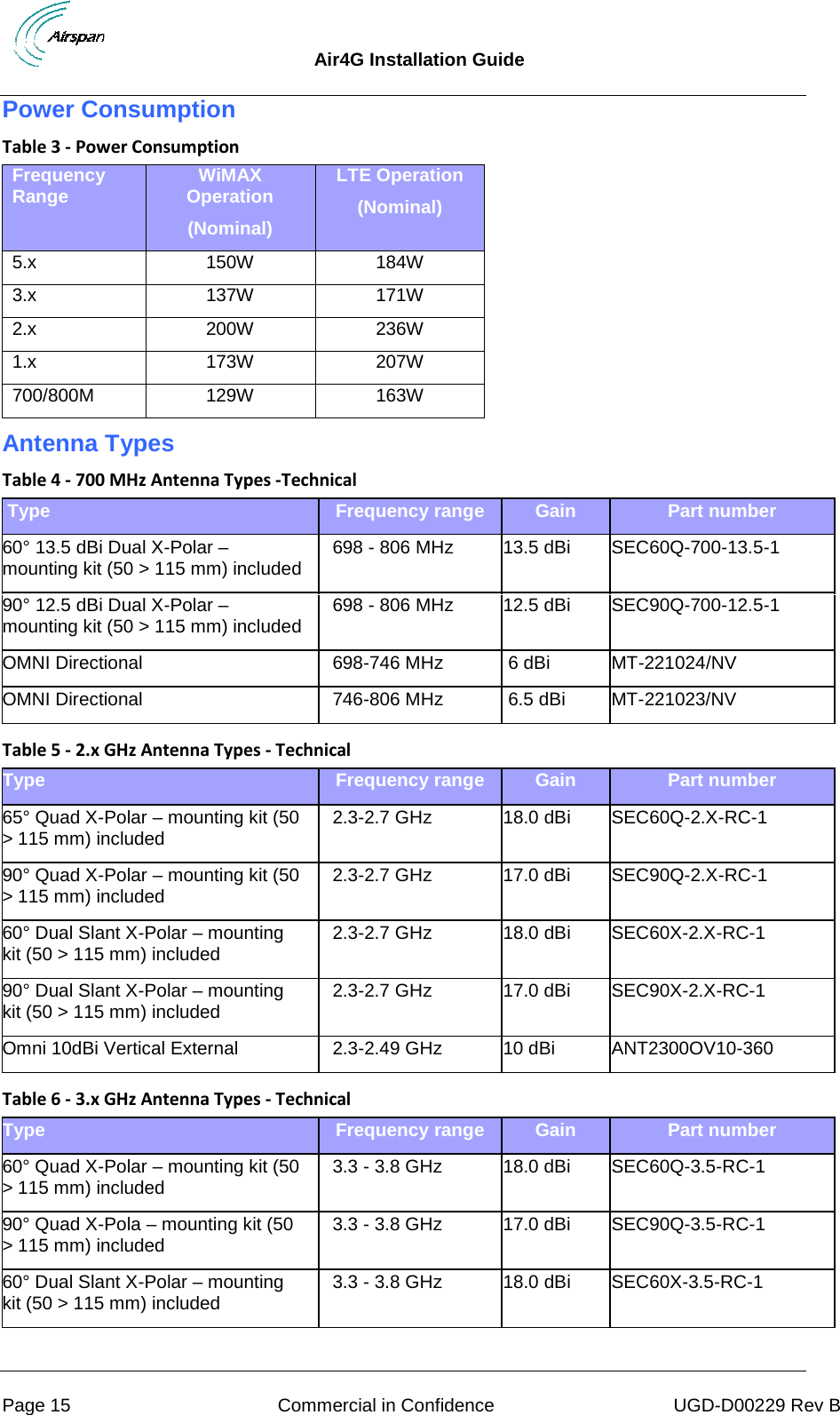
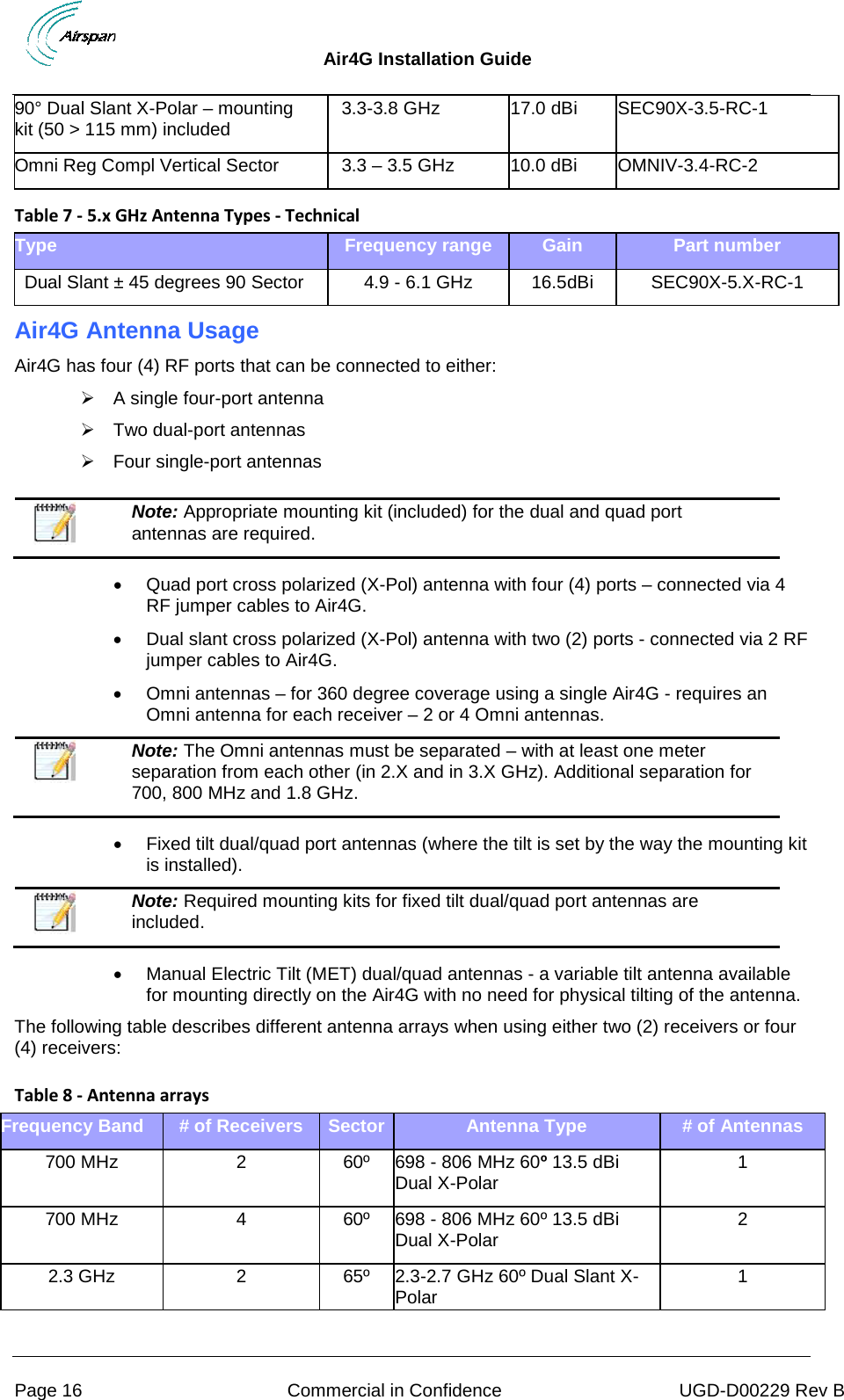
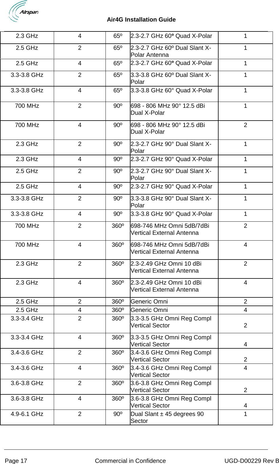
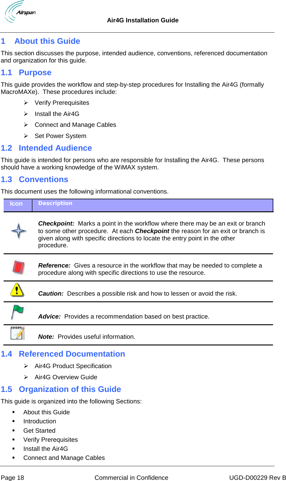
Airspan Networks LTE700F Base station of LTE fixed cellular system User Manual Air4G Installation Guide
Airspan Networks Inc Base station of LTE fixed cellular system Air4G Installation Guide
UserManual.wiki
>
Airspan Networks
>
LTE700F User Manual
User_manual
Navigation menu
Upload a User Manual
Namespaces
Wiki Guide
HTML
PDF
Info
Views
User Manual
Discussion / Help
Navigation
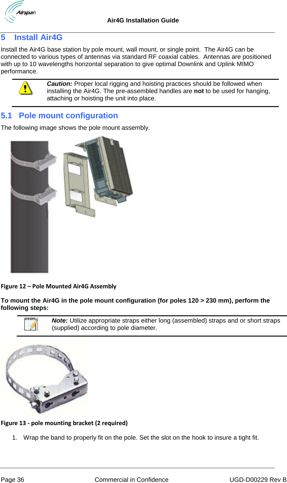
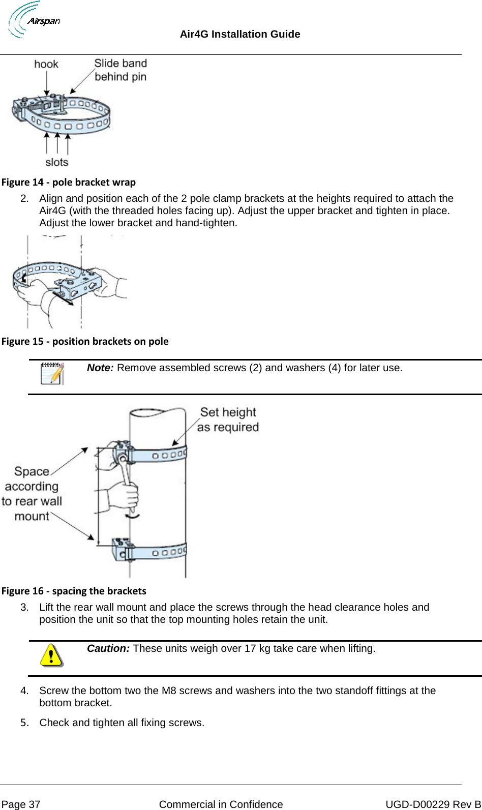
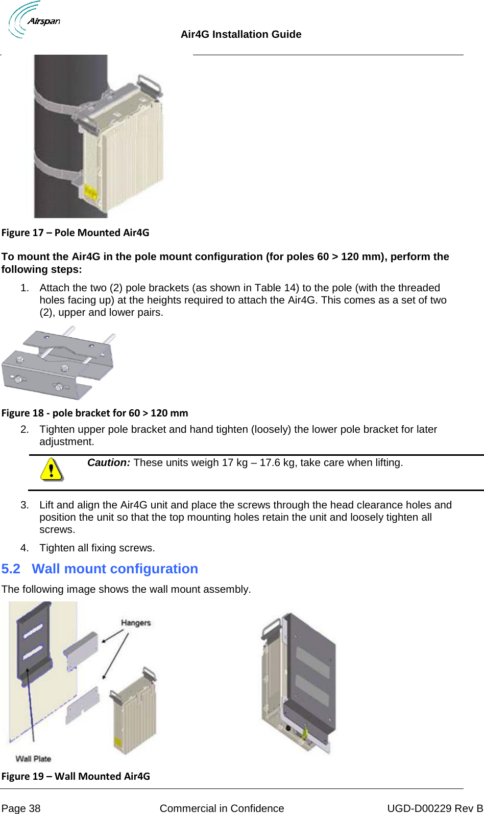
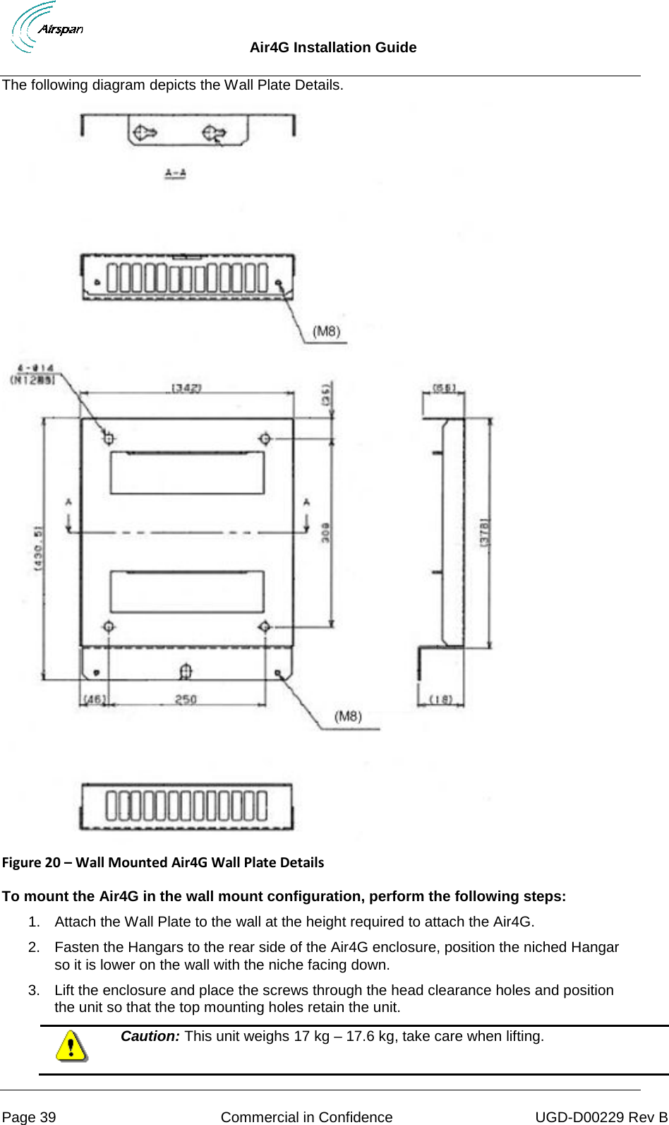
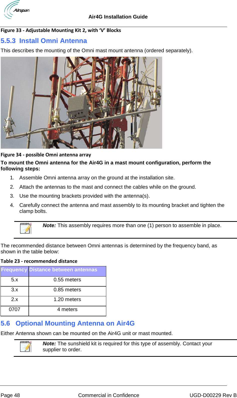
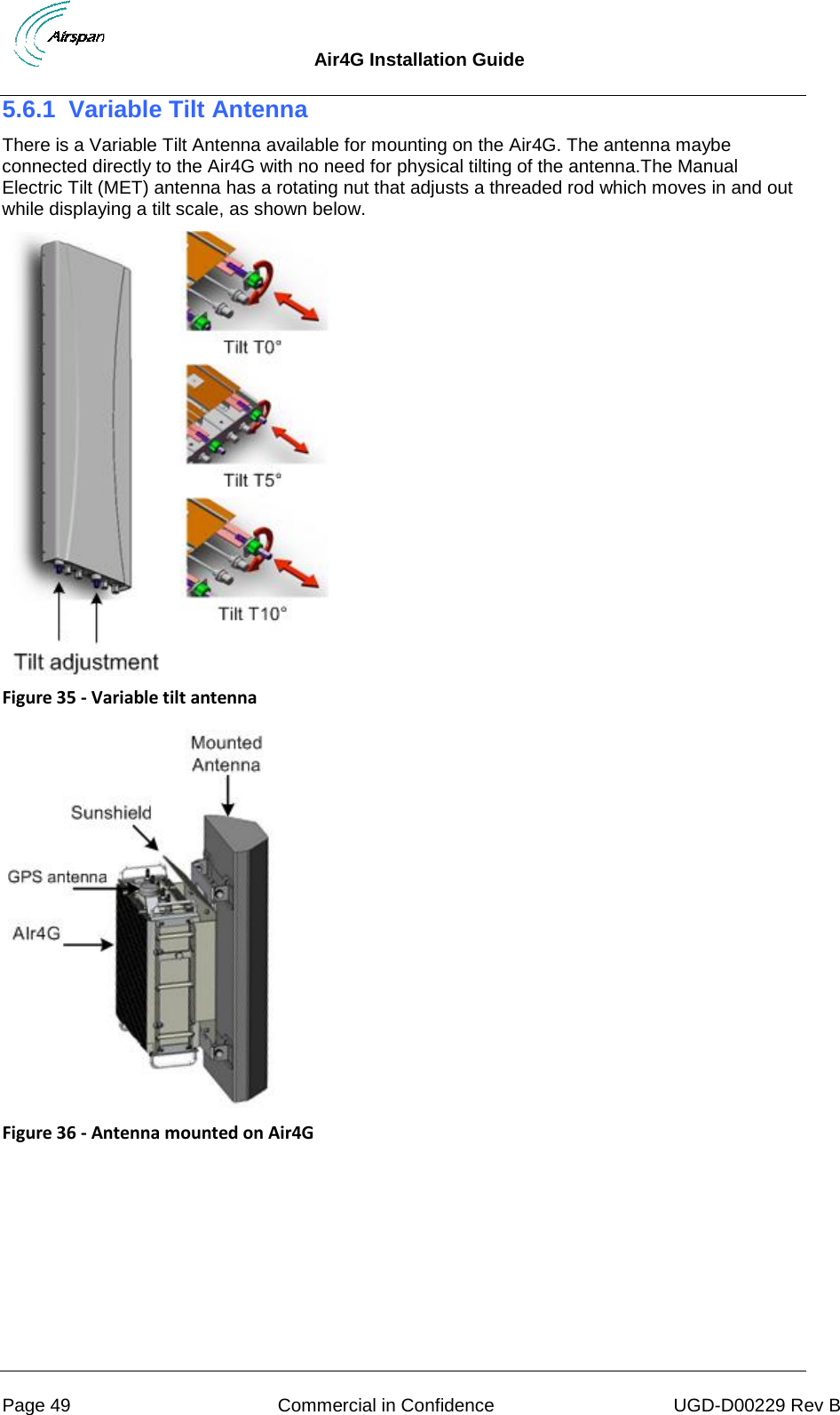
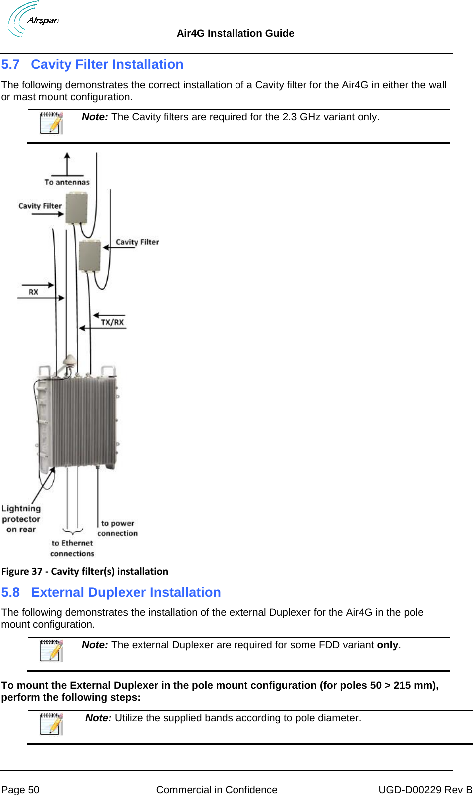
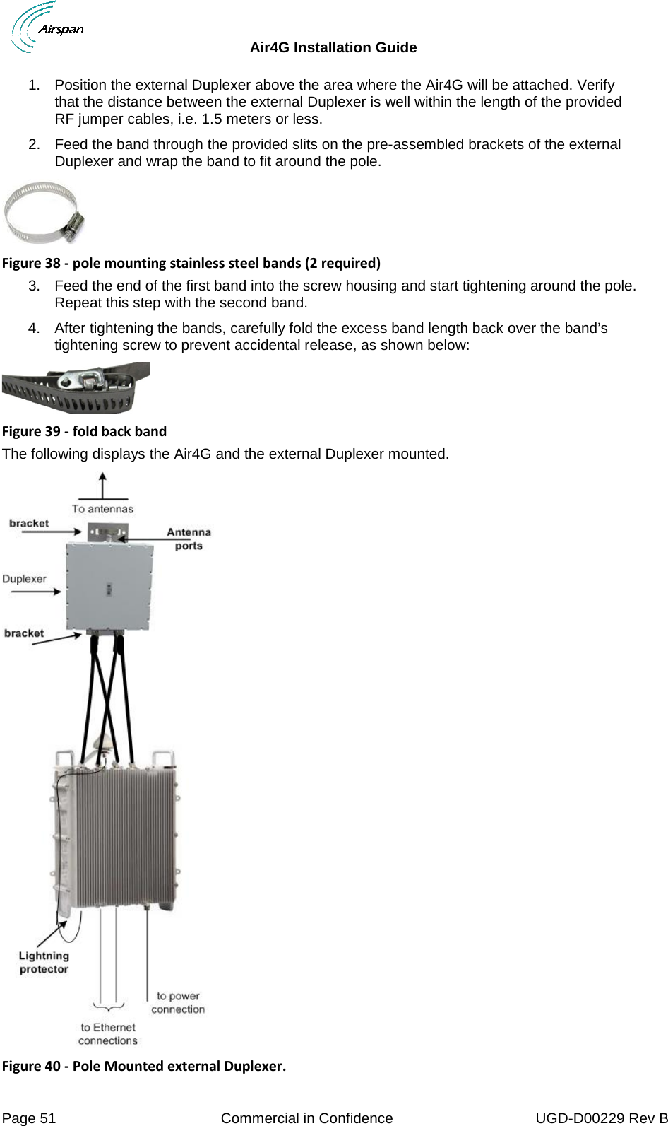
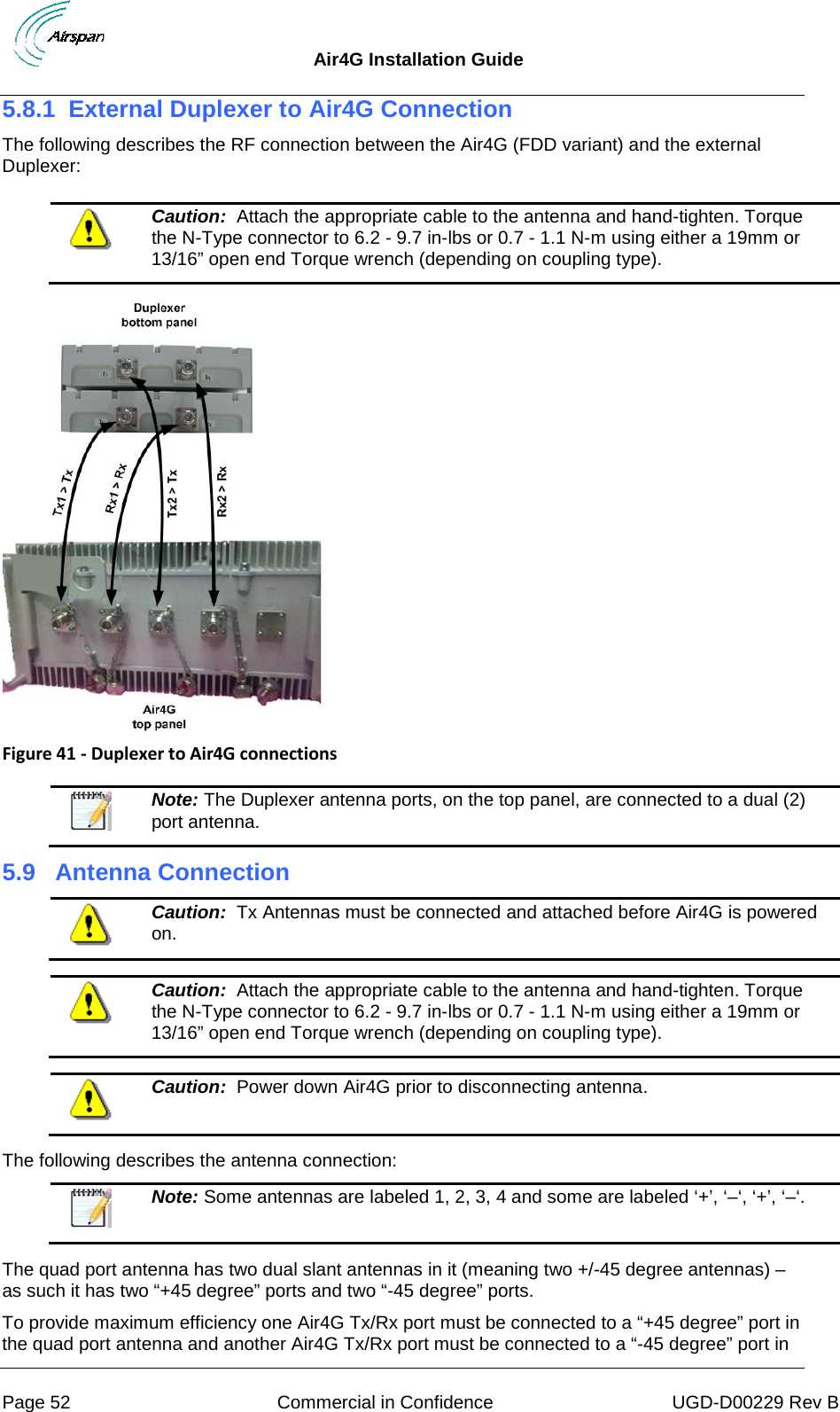
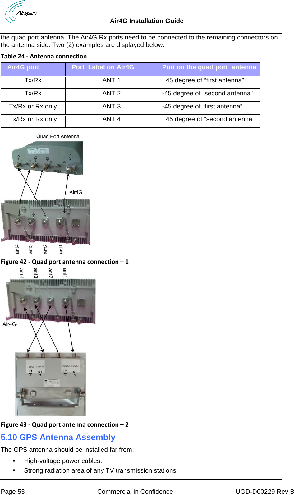
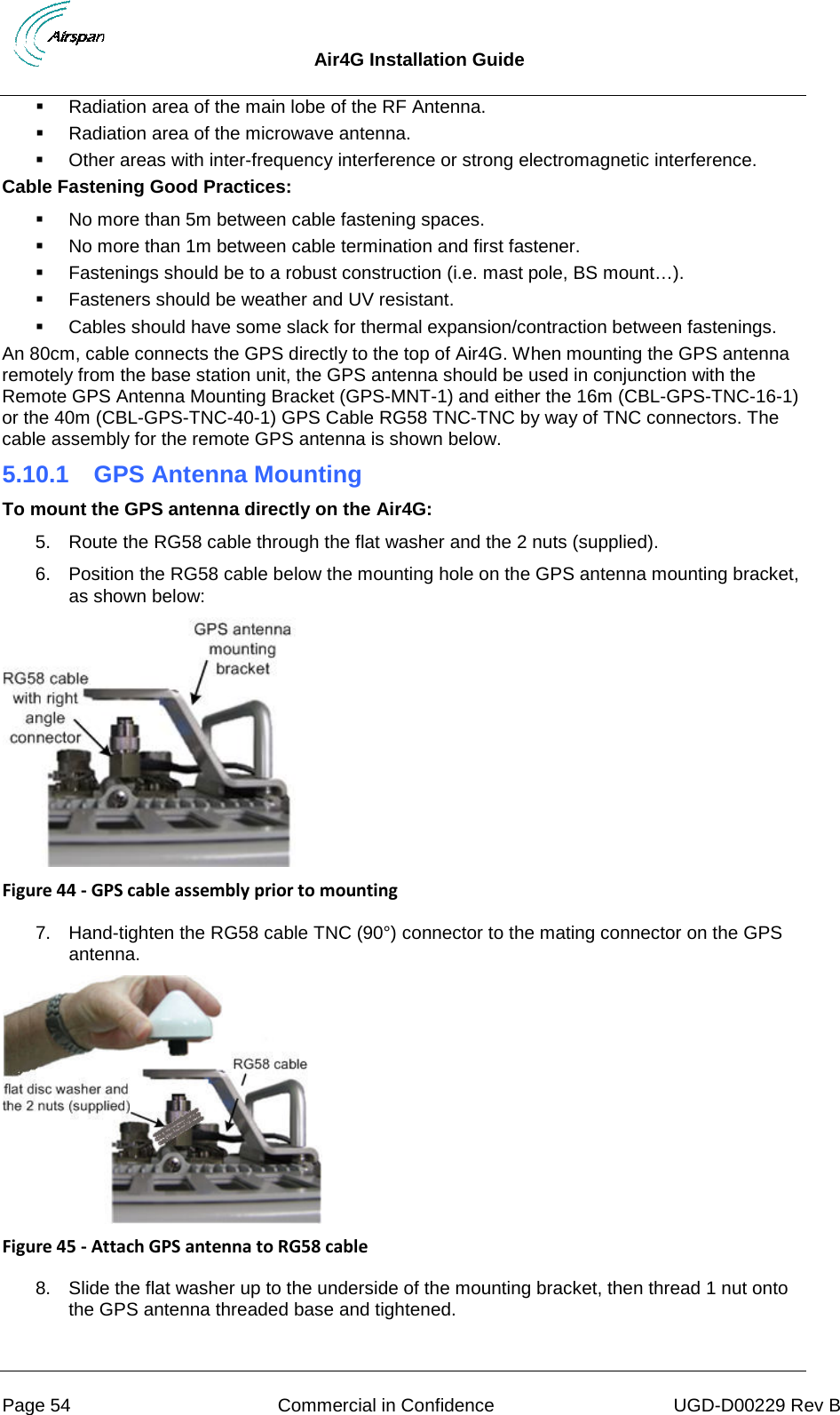
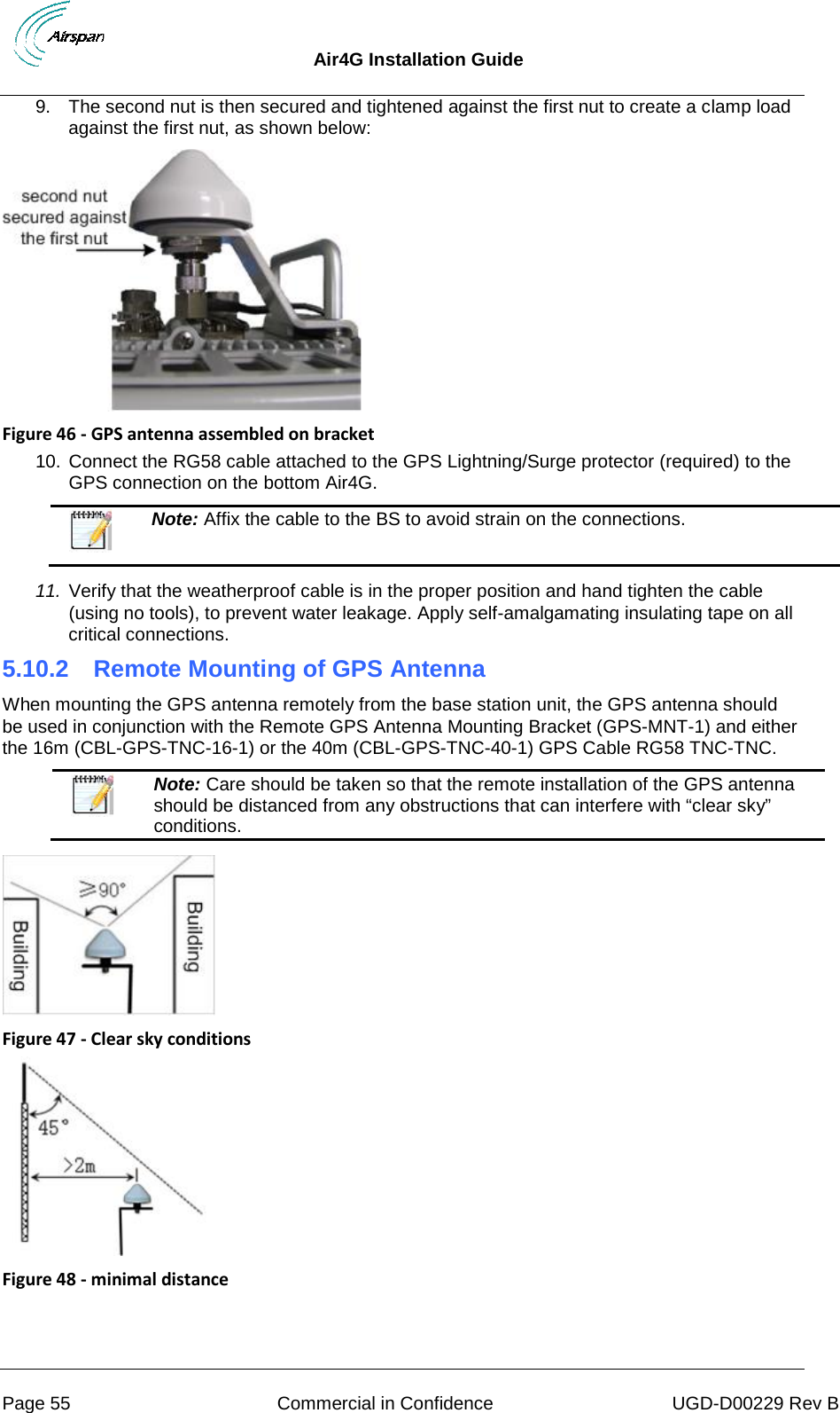
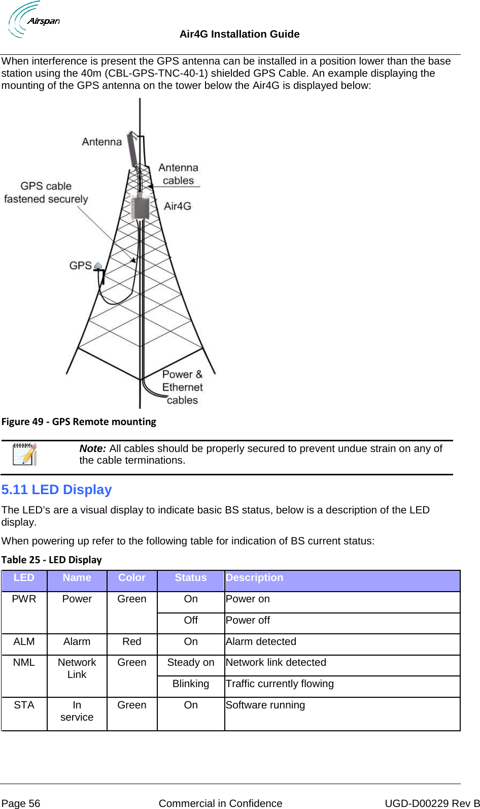
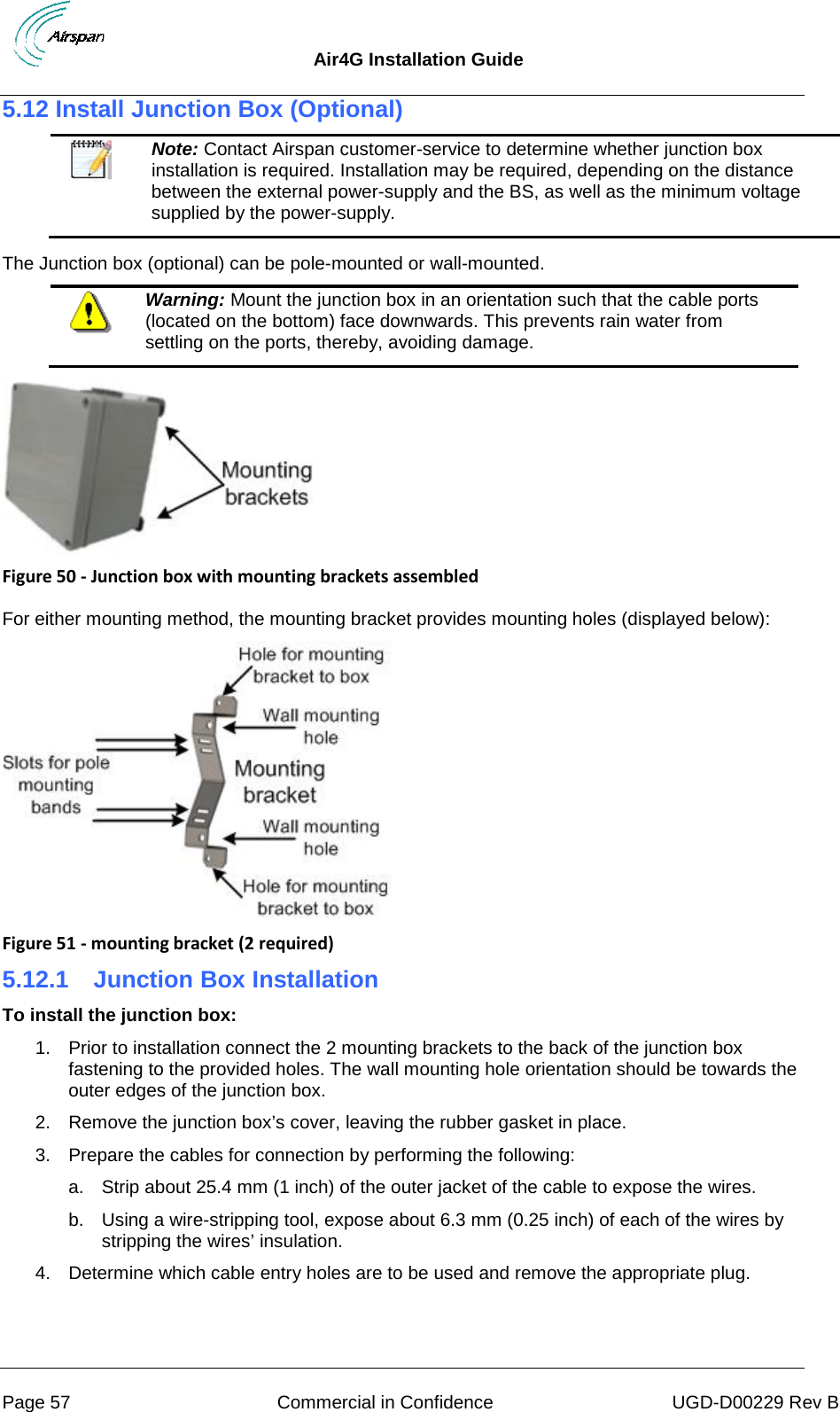
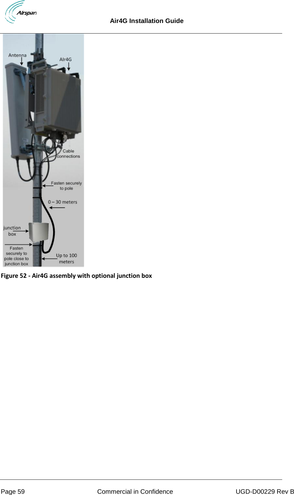
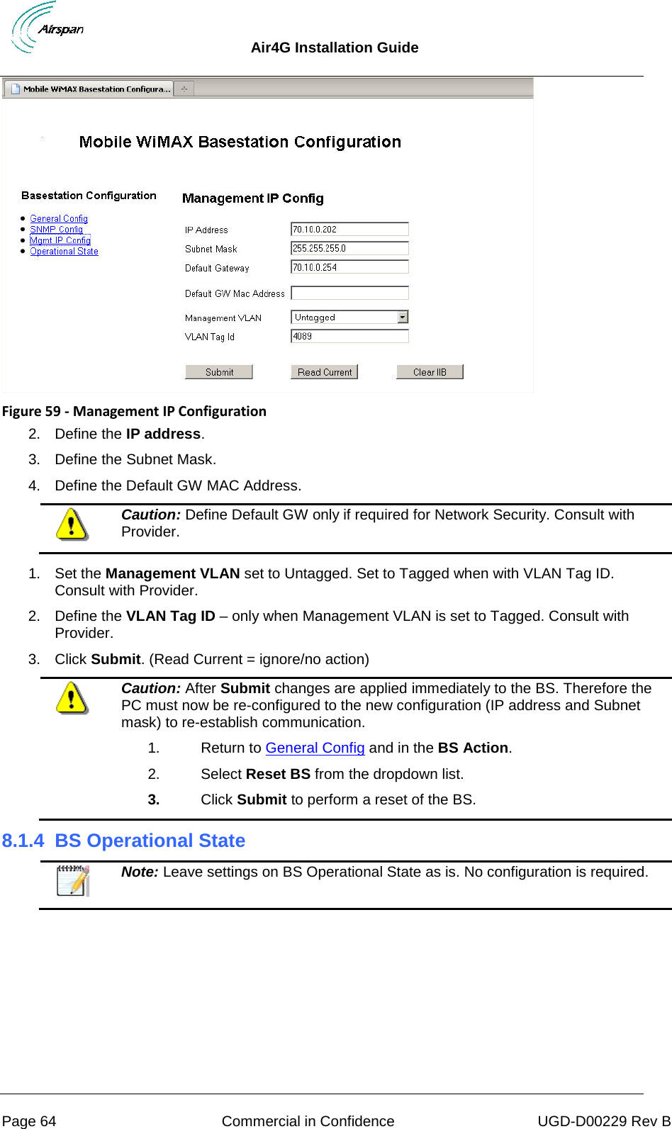
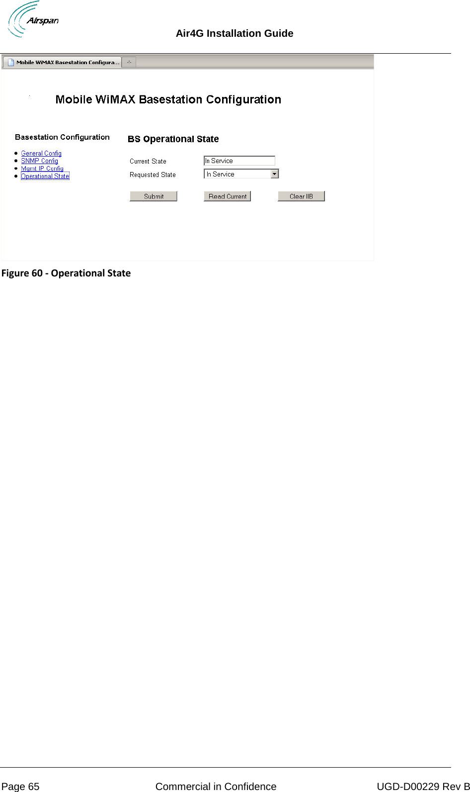
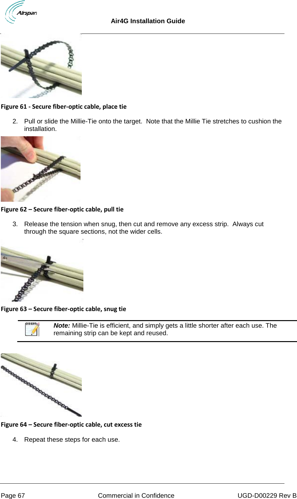
![Air4G Installation Guide Page 19 Commercial in Confidence UGD-D00229 Rev B Set Power System Appendixes [Review Job Sheet, Securing & Connecting the Fiber-Optic cable, Glossary of Terms, Installation Checklist, Contact information and Revision history]](https://usermanual.wiki/Airspan-Networks/LTE700F/User-Guide-2023062-Page-19.png)