Airspan Networks MMAX3605 Base station radio User Manual MacroMAXe Installation Guide
Airspan Networks Inc Base station radio MacroMAXe Installation Guide
UserManual.wiki
>
Airspan Networks
>
MMAX3605 User Manual
>
Users manual
Contents
1.
Description of High band blocking
2.
Users manual
Users manual
Navigation menu
Upload a User Manual
Namespaces
Wiki Guide
HTML
PDF
Info
Views
User Manual
Discussion / Help
Navigation
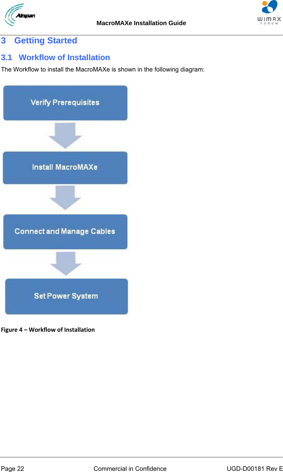
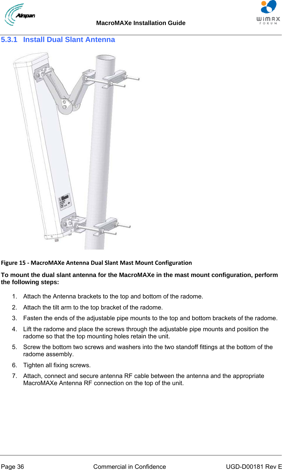
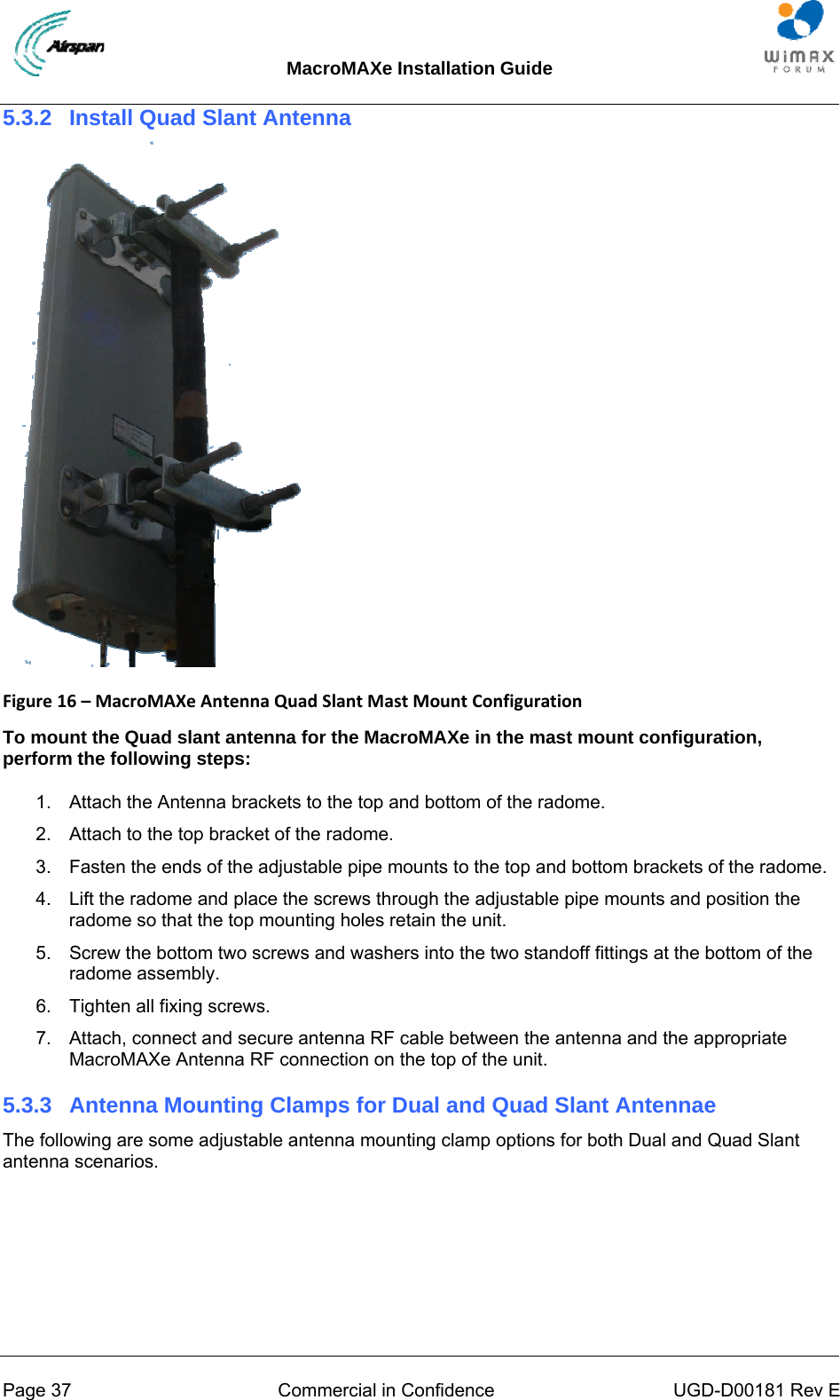
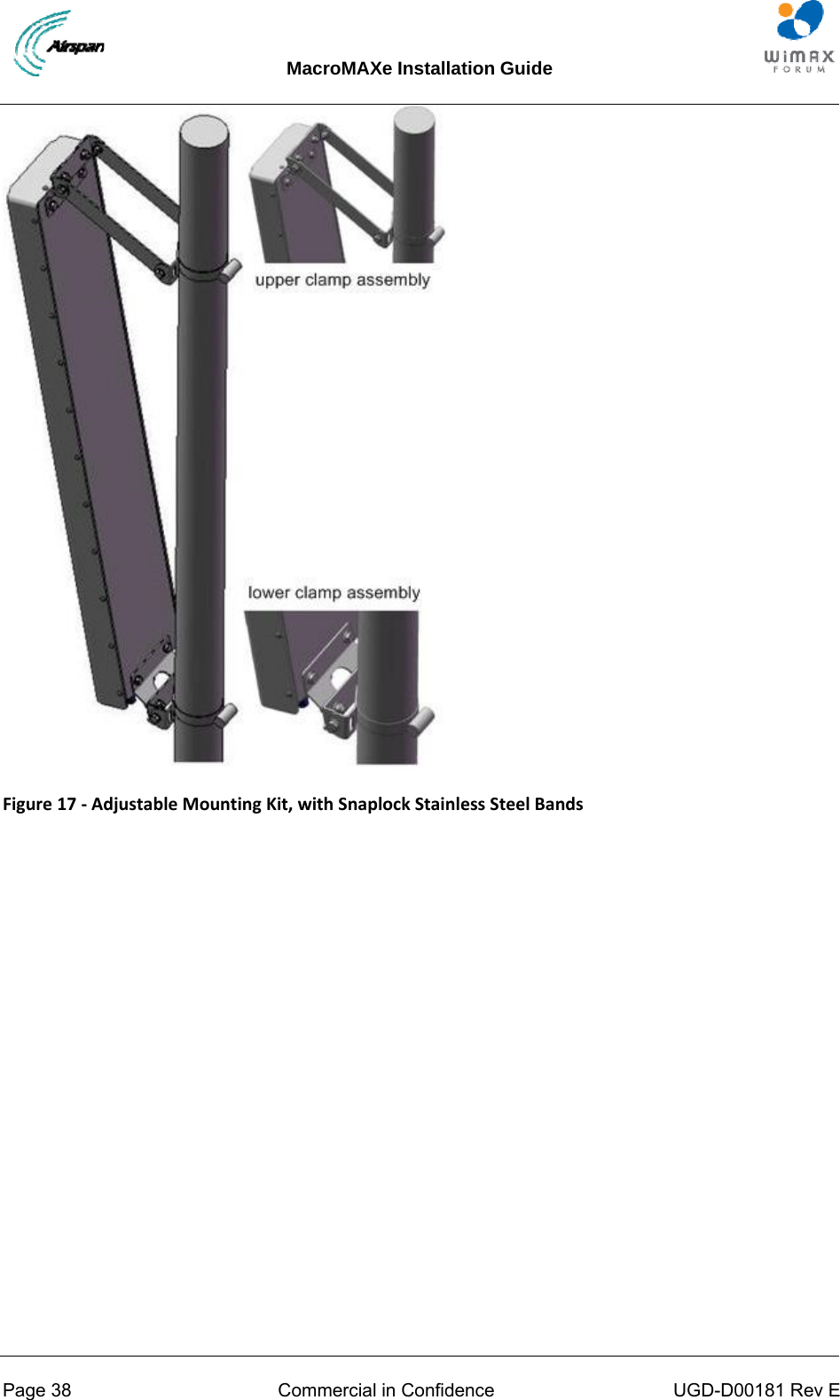
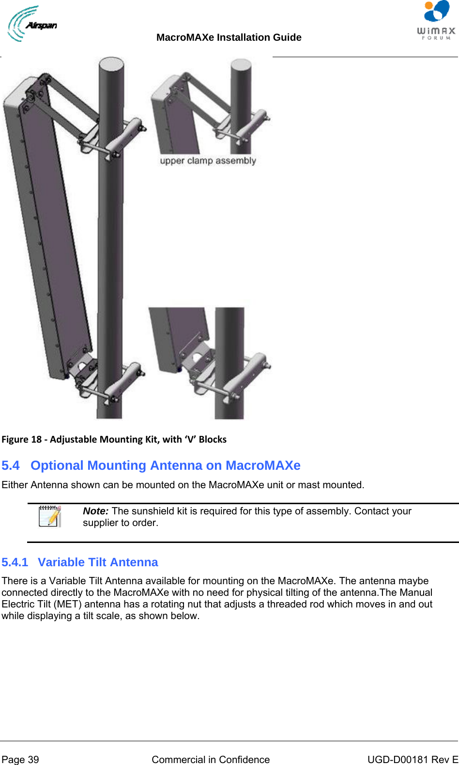
![MacroMAXe Installation Guide Page 18 Commercial in Confidence UGD-D00181 Rev E About this Guide Introduction Get Started Verify Prerequisites Install the MacroMAXe Connect and Manage Cables Set Power System Appendixes [Sample Job Specification, Troubleshooting, Glossary of Terms, Installation Checklist, Contact information and Revision history]](https://usermanual.wiki/Airspan-Networks/MMAX3605.Users-manual/User-Guide-1250804-Page-18.png)