Airtronics ATX037 Transmitter and Module for Radio Control User Manual
Airtronics Inc Transmitter and Module for Radio Control Users Manual
UserManual.wiki
>
Airtronics
>
ATX037 User Manual
Users Manual
Navigation menu
Upload a User Manual
Namespaces
Wiki Guide
HTML
PDF
Info
Views
User Manual
Discussion / Help
Navigation

![Page 14End Point Adjustment Page F1 (EPA)[ST] Steering End Point AdjustmentEnd point adjustment is used to adjust the proper amount of servo movement on the model’s steering angle to steer left and right and/or adjust the carburetor throttle arm stroke, the high point of an ESC and brake stroke. While the M11 is set for 4 channels, this EPA function is also adjustable for 3rd BRAKE or AUX Channel) and for 4th channel of brake.A model’s turning radius can differ from left to right because of variations in linkage, suspension balance, tire diameter or weight distribution of the vehicle. In such cases, the left and right servo steering angle is adjustable. Before making the end point adjustment, you must set the servo to the neutral position. To nd the center position, adjust the servo horn to approximately center position, and then make ne adjustments using the sub-trim.Next, press the function select key and move the cursor to [ST] in EPA.To set the steering end point on the right side, turn the steering wheel fully clockwise and depress the Inc.+ or Dec.- key. To set the left steering end point, do the same with the steering wheel turned fully counterclockwise.Setting range 0% to 150%Default setting 100%1.2.3.IMPORTANTNote: Setting the steering dual rate and steering end points excessively high may cause a dead point on the servo, resulting in improper operation.](https://usermanual.wiki/Airtronics/ATX037/User-Guide-545619-Page-14.png)
![Page 15Trm 5 (bottom)[TH] Throttle End Point AdjustmentPress the function select key and move the cursor to [TH] in EPA.To adjust the high end of throttle movement on a gas -powered car, pull the throttle trigger all the way to the high side and adjust by pressing the Inc.+ or Dec.- key.To adjust the brake side, push the throttle trigger all the way to the brake side and adjust by pressing the Inc.+ or Dec.- key.With an ESC, the high side and brake side are both ordinarily set to 100% and then the high point and brake point are set on the ESC.(Setting procedures may vary depending on the type of ESC.)Setting range 0% to 140%Brake side 0% to 160%Standard setting 100%Test run your vehicle to arrange the brake adjustment by using TRM5 switch on the grip. You can vary the setting at EPA-B by adjusting with TRM5. While the M11 is set for 4 channels, setting value may vary at the same time. Throttle end point adjustment is used to adjust the carburetor stroke, high point of an ESC, or the brake stroke.1.2.3.NOTEWith gas-powered model linkage, if the linkage stroke is set too wide, the servo may lock up. This results in fatal damage and may cause the vehicle to runaway.TIPBrake adjustment TR5 switch can be assignable with other trim switches.](https://usermanual.wiki/Airtronics/ATX037/User-Guide-545619-Page-15.png)
![Page 16[3ch] AUX End Point Adjustment ( with 3ch - BRAKE INH )NOTE: I order to set any functions for AUX 3 and AUX 4, you must rst set the channel setting from 2 to 4 channel. To change from 2 to 4 channel, go to the F3 page on the transmitter, move the function menu cursor to SET-Up and change the channel number in the programming area on the transmitter screen.[3ch] 3CH-BRAKE End Point Adjustment ( with 3ch - BRAKE ACT )1.The AUX channel can be used for functions such as needle control or for other uses. The end point adjustment allows ne adjustment of the maxi-mum servo travel. Further, the high end point and low end point can be set independently, which provides great exibility of adjustment. Be sure that channel 4 is selected in the set-up menu and that 3CH-BRAKE is set to INH in the BR-MIX menu. It is essential to set the M11 as “4channel” in order to use these functions. Press the function select key and move the cursor to [3ch] in EPA.To select the low side AUX setting, turn the dial counterclockwise and de-press the Inc.+ or Dec.- key. To select the high side setting, do the same after turning the dial clockwise.Setting range 0% to 150%Standard setting 100%TIPThe standard setting of the AUX key assign trim function is on DIAL. * This dial can be assignable with other trim switches such as TRM 1 to TRM5.2.3.With 4-channel settingMake sure that the channel 4 is selected in the set-up menu and that 3CH-BRAKE is set to ACT in the BR-MIX menu. It is essential to set this function in order to activate this set up menu. Press the function select key and move the cursor to [3ch] in EPA.Push the throttle trigger all the way to the brake side and then adjust by pressing the Inc.+ or Dec.- key.Setting range 0% to 160%Standard setting 100%If it is necessary to arrange the EPA brake adjustment during the operation of the vehicle, use trimmer TRM5 on the grip.When using 3rd channel as the additional BRAKE channel, the end point adjustment can be separately set from the other BRAKE channel.1.2.3.IMPORTANT* Since this channel is exclusively for braking purpose, setting of EPA covers only at the BRAKE side.4.](https://usermanual.wiki/Airtronics/ATX037/User-Guide-545619-Page-16.png)
![Page 17[4ch] 4CH - BRAKE End Point AdjustmentTH 3CHEPA of TH EPA of 3ch1. Be sure that the channel 4 is selected in the set-up menu. It is essential to set this function in order to activate this set up menu. Press the function select key and move the cursor to [4ch] in EPA.Push the throttle trigger all the way to the brake side and then adjust by pressing the Inc.+ or Dec.- key.Setting range 0% to 160%Standard setting 100%If it is necessary to arrange the EPA brake adjustment, during the opera-tion of the vehicle, use trimmer TRM5 on the grip.The 4th channel is exclusively for braking purpose only. When using the 4th channel as the additional BRAKE channel, end point adjustment can be separately set from the other BRAKE channel.IMPORTANTSince this channel is exclusively for braking purpose, setting of EPA covers only at the BRAKE side.TIPBalance bar graphThe bar graph appearing at the bottom of the screen is useful when setting the brake on more than two channels.The graph indicates the center position of two EPA values. Use it as a guide to nding a good brake balance. The lower triangles in the graph indicate the respective EPA values.When 3CH-BRAKE is set to ACT, the ENTER key switches the balance display between TH-3CH and 3CH-4CH. When 3CH-BRAKE is set to INH, the bar graph shows only the TH-4CH balance.3.2.](https://usermanual.wiki/Airtronics/ATX037/User-Guide-545619-Page-17.png)
![Page 18Exponential Page F1 (EXP)[ST] Steering ExponentialQuick(1% to 100%) Quick(1% to 100%)Mild(-1% to 100%) Mild(-1% to 100%)Normal0% Normal0%Neutral positionAmount of servo operationAmount of servo operationAmount of steering wheel operation on the L side (amount of throttle trigger operation on the H side)Amount of steering wheel operation on the R side (amount of throttle trigger operation on the B side)1.3.2.This function varies the amount of servo action with respect to manipulation of the steering wheel or throttle trigger based from the neutral position. Increasing the numeric value makes action quicker, while reducing it makes action slower.Press the function select key and move the cursor to [ST] in EXP.Set the EXP quantity by pressing the Inc.+ or Dec.- key.Setting range -100% to 100%Standard setting 0TWEAK settingUse the TWEAK setting when you want to ne-tune the left-right steering bal-ance.First, move < or > to below TWEAK with the ENTER key.To adjust the left side steering, turn the steering wheel to the left and set the arrow direction to <. To adjust the right side steering, turn the steering wheel to the right and set the arrow direction to >.Set the TWEAK quantity by pressing the Inc.+ or Dec.- key.Setting range -20 to 20Standard setting 0Three settings, Mild, Linear and Quick, allow you to set the most effective steering response for your model vehicle. Generally, if your model vehicle over-steers, reduce the numeric value. If it under-steers, increase the numeric value.](https://usermanual.wiki/Airtronics/ATX037/User-Guide-545619-Page-18.png)
![Page 19[TH Throttle Exponential4. INH/ACT setting of EXPIn order to activate the EXP function, select ACT; to deactivate, select INH.Using the ENTER key, move > to the right side of EXP.Select INH or ACT by pressing the Inc.+ or Dec.- key.Press the function select key and move the cursor to [TH] in EXP.Make sure that > appears to the right of H, and then set the EXP amount for the high side of TH by pressing the Inc.+ or Dec.- key.Setting range -100% to 100%Standard setting 0Move > to the right of B using the ENTER key, and then set the EXP amount for the brake side of TH by pressing the Inc.+ or Dec.- key.Setting range -100% to 100%Standard setting 0INH/ACT setting in EXPSelect ACT to activate the EXP function. Select INH to deactivate. Using the ENTER key, move > to the right side of EXP.Select INH or ACT by pressing the Inc.+ or Dec.- key.IMPORTANTAbout the INH/ACT setting of EXPThe INH/ACT setting of EXP in the menu can also be switched to any desired key switch by using the key assigning function. By using this function, switch-ing the EXP “ON” or “OFF” can be selected during operation.Throttle exponential can be adjusted from Mild, Linear and Quick. Generally, reduce the numeric value on a slippery track or with models that have powerful response. Increase the numeric value on a high-grip track or with power units that have lower torque. The high side and brake side can be set independently.3.2.1.4.](https://usermanual.wiki/Airtronics/ATX037/User-Guide-545619-Page-19.png)
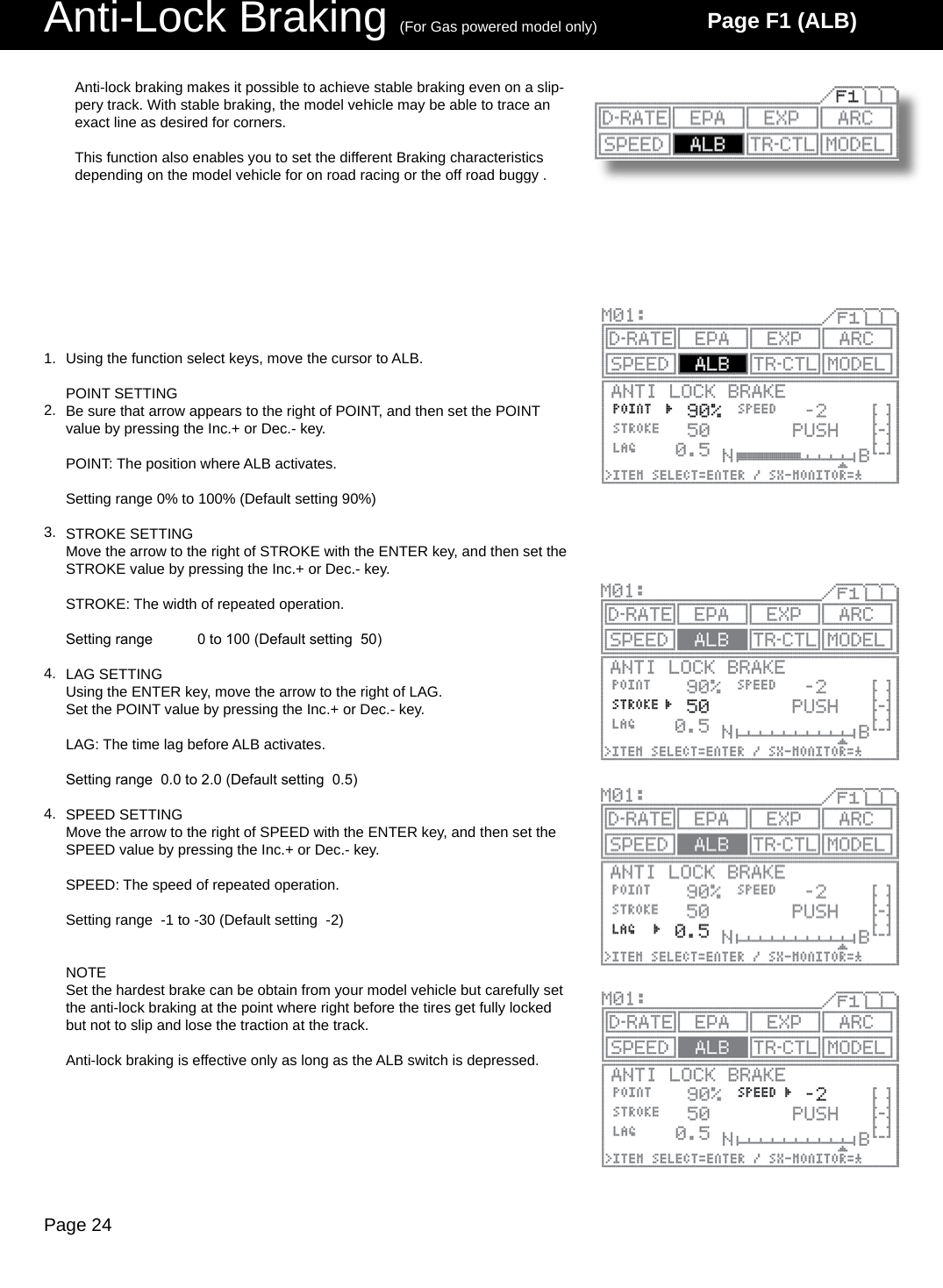
![Page 20Adjustable Rate Control Page F1 (ARC)[ST] Steering Adjustable Rate ControlQuick(1% to 100%) Quick(1% to 100%)Mild(-1% to 100%) Mild(-1% to 100%)Normal0% Normal0%Neutral positionAmount of servo operationAmount of servo operationAmount of steering operation on the L side (amount of operation on the throttle H side)Amount of steering operation on the R side (amount of operation on the throttle B side)This function varies the amount of servo action with respect to manipulation of the steering wheel or throttle trigger.Increasing the rate setting makes action quicker, while reducing it makes ac-tion milder.The changeability of the variable point on the ARC enables to adjust delicate steering and throttle work during the operation. (-1% to -100%) (-1% to -100%)Steering response can be variably adjusted from mild through liner or to quick. In general, if the model vehicle tends to have over-steers, reduce the numeric value, and if the vehicle tends to have under-steers, increase the numeric value.RATE SETTINGPress the function select key and move the cursor to [ST] in ARC.Be sure that arrow points to the RATE, and then set the RATE for ARC by pressing the Inc.+ or Dec.- key.Setting range -100% to 100% (Default setting 0)POINT settingMove arrow to POINT with the ENTER key, and then set the POINT value by pressing the Inc.+ or Dec.- key.Setting range 5 to 95 (Default setting 50)INH/ACT setting for ARCIn order to activate the ARC function, select ACT, and to deactivate, select INH.Using the ENTER key, move the arrow to the left side of ARC.Select INH or ACT by pressing the Inc.+ or Dec.- key.1.2.3.4.](https://usermanual.wiki/Airtronics/ATX037/User-Guide-545619-Page-20.png)
![Page 21[TH] Throttle Adjustable Rate ControlPress the function select key and move the cursor to [TH] in ARC.RATE SETTINGBe sure that the arrow appears below RATE.To adjust the high side throttle setting, pull the throttle trigger all the way to change the arrow direction to the throttle rate.To adjust the brake side throttle setting, push the throttle trigger all the way to the brake side, and watch the arrow direction change to the brake side.Set the RATE by pressing the Inc.+ or Dec.- key.Setting range -100 to 100 (Default setting 0)POINT SETTINGMove the arrow to below POINT with the ENTER key.To adjust the high side throttle setting, pull the throttle trigger all the way to the high side, this will change the arrow to the throttle side.To adjust the brake side throttle setting, push the throttle trigger all the way to the brake side, and the arrow will change to the brake side.Set the POINT value by pressing the Inc.+ or Dec.- key.Setting range 5 to 95 (Default setting 50)INH/ACT setting for ARCTo activate the ARC function, select ACT, and to deactivate, select INH.Using the ENTER key, move > to the right side of ARC.Select INH or ACT by pressing the Inc.+ or Dec.- key.IMPORTANTAbout the INH/ACT setting of ARCThe INH/ACT setting of ARC in the menu can be also switch to any desired key switch by using the key assign function. By using this function, Activation ,of the ARC “ON” or “OFF” can be selected during the operation.Throttle characteristic can be variably adjusted from mild through linear or to quick. In general, reduce the numeric value on slippery track or with models that have powerful response, and increase it on high-grip track or with power units that have lower torque. The high side and brake side can be set independently.1.2.3.4.](https://usermanual.wiki/Airtronics/ATX037/User-Guide-545619-Page-21.png)
![Page 22Speed Page F1 (SPEED)[ST] Steering Servo SpeedL edge R edgePOINTFORWARDRETURN RETURNFORWARDNThe SPEED setting does not affect steering when the wheel is located within the shaded areas outside the POINT positions.Neutral POINT(5% 100%)(5% 100%)The SPEED setting does not affect steering when the wheel positioning is located within the shaded areas outside the POINTS.Using the function select keys, move the cursor to [ST] in SPEED.FORWARD SETTINGMake sure that the arrow appears to the right of FORWARD, and then set the FORWARD value by pressing the Inc.+ or Dec.- key.Setting range 0 to 100 (Default setting 0)RETURN SETTINGMove arrow to RETURN with the ENTER key, and then set the RETURN value by pressing the Inc.+ or Dec.- key.Setting range 0 to 100 (Default setting 0)POINT SETTINGMove the arrow to the right of POINT with the ENTER key, and then set the POINT value by pressing the Inc.+ or Dec.- key.Setting range 5% to 100% (Default setting 100%)INH/ACT SPEEDTo activate the SPEED function, select ACT, and to deactivate, select INH.Using the ENTER key, move > to the right of SPEED.Select INH or ACT by pressing the Inc.+ or Dec.- key.NOTEWhen driving a model vehicle, proper steering is vital, and excessive steering is to be avoided at all times. The steering speed setting helps to limit exces-sive steering, which will enable you to achieve smoother cornering.It is advisable to use both Steering Speed & Exponential functions together which enable you to achieve the best combination of steering operation.This function slows down the steering servo speed during steering. Speed can be set separately for steering movement say from neutral to certain point and return directions. But note that actual steering operation is slower than in its set speed of the servo, this function does not affect any. 1.2.3.4.5.](https://usermanual.wiki/Airtronics/ATX037/User-Guide-545619-Page-22.png)
![Page 23[TH] Throttle Servo SpeedFORWARDNeutralNPOINT(5% 100%)Hi edge B edgeThe SPEED setting does not affect throttle operation when the throttle trigger is located within the shaded areas outside the POINT positions.Using the function select keys, move the cursor to [BR] in SPEED.FORWARD SETTINGMake sure the arrow appears to the right of FORWARD, and then set the FORWARD value by pressing the Inc.+ or Dec.- key.Setting range 0 to 100 (Default setting 0)POINT SETTINGMove the arrow to the right of POINT with the ENTER key, and then set the POINT value by pressing the Inc.+ or Dec.- key.Setting range 5% to 100% (Default setting 100%)INH/ACT SPEEDTo activate the SPEED function, select ACT, and to deactivate, select INH.Using the ENTER key, move the arrow to the right of SPEED.Select INH or ACT by pressing the Inc.+ or Dec.- key.This function slows down the throttle servo during throttle operation. This setting affects only the FORWARD side of the brake.The SPEED setting does not affect throttle operation when the throttle trigger positioning is located within the shaded areas outside the POINT. (Only affect from the neutral to the point set at.)1.2.3.4.NOTEIt is advisable to use both Throttle’s Speed & Exponential functions together which enable to achieve best combination of the steer-ing operation for the model vehicle. IMPORTANTAbout the INH/ACT setting for SPEEDThe INH/ACT setting of SPEED in the menu can be also switch to any desired key switch by using the key assign function. By using this function, switching the SPEED “ON” or “OFF” can be selected during the operation.](https://usermanual.wiki/Airtronics/ATX037/User-Guide-545619-Page-23.png)

![Page 27Model Page F1 (MODEL)[SELECT] Model Select[NAME] Model NameUsing the function select keys, move the cursor to [NAME] in MODEL.Using the asterisk key or the ENTER key, move the cur-sor (“_”) to the point when you want to enter text.Select a character by pressing the Inc.+ or Dec.- key.Repeat steps 2) and 3) for each subsequent character.Setting range A – Z, a – z, 0 – 9, symbols, spaceNOTEGroup of characters can be ip through in sequence A->a->0->!->space-> by simultaneously pressing the Inc.+ and Dec.- keys.When entering a character in a position occupied by a space, group can be selected from the preceding char-acter by rst pressing the Dec./- key. This is useful when entering several characters from the same group.This menu enables you to make settings related to model select (SELECT), model name (NAME), and model copy/model clear (COPY/CLEAR) func-tions.Data for up to 30 models, M01 to M30, can be stored in the M11’s high capacity, built-in EEPROM memory.Using the function select keys, move the cursor to [NAME] in MODEL.Select the model to be recalled by pressing the Inc.+ or Dec.- key.Setting range M01 to M30Data can be easily stored for any models M01 to M30.Since the previous model memorys are stored automatically, there is no risk for accidental erasing.1.2.NOTEThe model changes immediately upon selection.Pages can be ip through in sequence such as M01->M07->M13->M19->M25->M1…by simultaneously pressing the Inc.+ and Dec.- keys.! CAUTIONDo not attempt to change the model when the model vehicle’s receiver is being turned on under the actual operational condition resulting that Model vehicle may go runaway or the servo may be damaged being set with other servo setting. Model names can be registered as consisting of up to 12 letters, numerals, or symbols.1.2.3.4.](https://usermanual.wiki/Airtronics/ATX037/User-Guide-545619-Page-27.png)
![Page 28[COPY/CLEAR] Model Copy / Model ClearCOPY MODEL DATAUsing the function select keys, move the cursor to [COPY/CLEAR] in MODEL.To copy data from the current selected (Master) model to another model (Slave), use the INC/+ or DEC/- keys to change the model numbers up or down to the model number you would like to copy the current model (Mas-ter) to.After you have selected the model number you wish to copy the current model (Master) to, press the ENTER key. The screen will now change and ask you:YES=<INC> and NO=<DEC>Press the INC/+ key to copy the current (Master) model to the new model (Slave) you have selected. Press the DEC/- key to return to the previous screen.To copy data from another model to the one your cur-rently using, use the star key to change the current model (Master) to (Slave). In turn the model you would like to copy from will now show (Master). The (Master) will always overwrite the (Slave).Select the model (Master) you want to copy from using the Inc.+ or Dec.- keys and then press the ENTER key.A conrmation screen appears, allowing to conrm that choice is correct. To proceed with copying, press Inc.+, or to cancel press Dec.- key. During copying, the mes-sage EXECUTING! appears until copying is completed.CLEARING MODEL DATAUsing the function select keys, move the cursor to [COPY/CLEAR] in MODEL.Using the star key, change the current model (Master) to (Slave).Press both INC/+ or DEC/- keys simultaneously to select the (- - -:CLEAR) model.Now press the ENTER key to select. The screen will change and ask, YES=<INC> or NO=<DEC>. Select yes to clear the current model or no to return to the previous screen. This operation clears all data for models M01 to M30.NOTE:CLEAR can be selected by simultaneously pressing Inc/+ and Dec/-.While clearing is in progress, the message EXECUTING! appears until operation is completed.This function enables you to copy data from the currently selected model to another, or to copy another model’s data into the model currently selected. Data can be cleared (initialize) on the current model that being selected.1.2.3.4.5.6.7.8.9.](https://usermanual.wiki/Airtronics/ATX037/User-Guide-545619-Page-28.png)
![Page 29Sub-Trim Page F2 (SUB-T)Corrects trim neutral for steering and throttle, making it possible to use the main trim from the center position. When adjusting linkages, this sub-trim allows to x the position in accurate center position.* This can also be used for brake sub-trim when using 4 channels. In this case, channels 3 and 4 can be set independently.Before adjusting linkage, be sure to set the main trimmers to center position (0).Attach the servo arm (servo saver arm) to the servo unit in the position that is closest to neutral.Using the function select keys, move the cursor to [ST] in SUB-T.Adjust the sub-trim to center the servo arm the the servo.Setting range 100L to 100R (Default setting 0)Adjust the other sub-trim settings in the same man-ner.! CAUTIONBe sure that the servo is as nearly centered as possible before making this adjustment. If the sub-trim and main trim set-tings are both offset to one side, an operational dead spot (a spot where the servo does not operate) may result.SteeringThrottleBrakeSteeringThrottle(Factory Default Trim Locations)(Set on 4 Channel)1.2.3.4.5.](https://usermanual.wiki/Airtronics/ATX037/User-Guide-545619-Page-29.png)
![Page 30Timer Page F2 (TIMER)SW3[LAP] Lap TimerAllows you to measure and record times for up to 99 laps (all models).Features a pre-alarm (PRE-ALM) that lets you set a pre-goal alarm time.Provides real-time display of the best lap (BEST), average lap (AVE), and total (TOTAL) lap times.Using the function select keys, move the cursor to [TH] in TIMER.Turning the lap timer (ON/OFF)Be sure that arrow appears below LAP, and then press Inc.+ or Dec.- to set the timer ON or OFF.Setting the goal time (GOAL)Press the ENTER key to move the arrow to GOAL, and then set the goal time by pressing the Inc.+ or Dec.- key.Setting range 00’10 to 60’00 In 00’10 increments (Default setting 60’00)Setting the pre-alarm (PRE-ALM)Press the ENTER key to move the arrow to PRE-ALM, and then set the pre-alarm by pressing the Inc.+ or Dec.- key.The pre-alarm is an alarm that sounds a few seconds before the goal time.Setting range OFF, 1s to 20s (Defailt setting 5s)With the standard conguration, the lap timer switch is set to SW3. Pressing SW3 starts measurement.Lap time is measured each time you press SW3. Once you press the switch, it is deactivated for 3 seconds.IMPORTANTAbout the timer switchThe timer switch can be freely assigned to another switch using the key as-sign function. Set the switch to the position that is most suitable.Three types of timers are provided for measuring lap, interval, and down (or up) times, and these three timers can be used simultaneously. A high degree of freedom and convenience is provided by the ability to use the key assign switch to perform simultaneous or independent operation.Separate tones can be assigned to each of the timers, making it easy to distinguish between them during simultaneous operation.The audible signal provided by the tone is complemented by a vibrator, which can be set to operate either in concert with the tone, or simultaneously.The operational status of the timers can also be checked from other menus (in the constant display area).1.2.3.4.5.](https://usermanual.wiki/Airtronics/ATX037/User-Guide-545619-Page-30.png)
![Page 31ENDING MEASUREMENTEnd measurement can be set in three different ways.By pressing the switch after the goal time is reached.By pressing the switch after the goal time is reached.By pressing and holding the switch for 3 seconds.VERIFYING MEASUREMENT RESULTSMeasurement results can be checked using the star key in the TIMER [LAP] menu while the timer is stopped.The display shows times for 9 laps at a time, Pages can be ip by using the Inc.+ or Dec.- key.Pressing Inc.+ and Dec.- simultaneously returns dis-play to the rst 9 laps.CONSTANT DISPLAY AREAThe timer status appears in the constant display area, and can also be checked from other menus.The timers appear in the timer display area in the order FUNC1>FUNC2>FUNC3, as set with the key assign switch. In the example at right, LAP appears as as-signed to FUNC1.! CAUTIONWhen measurement is started, the previous LAP measurement is cleared. There is no function that is provided for clearing the lap time.When measurement ends, the timer’s ON/OFF status changes to OFF. To re-start the timer, turn in ON as described in step 2).6.7.8.](https://usermanual.wiki/Airtronics/ATX037/User-Guide-545619-Page-31.png)
![Page 32[INT] Interval TimerSW3Using the function select keys, move the cursor to [INT] in TIMER.Turning the interval timer ON/OFFMake sure that the arrow appears below LAP, and then press Inc.+ or Dec.- to set the timer ON or OFF.Setting the interval minute timer (MIN)Press the ENTER key to move the arrow to the right of MIN, and then set the timer by pressing the Inc.+ or Dec.- key.The interval minute timer will not function when it is set as 00’.Setting range 00’ to 99’ 01’ increments (1-minute increments)(Default setting 00’)Setting the interval second timer (SEC)Press the ENTER key to move the arrow to the right of SEC, and then set the timer by pressing the Inc.+ or Dec.- key.Setting range 00” to 59” 01” increments (1-second increments)(Default setting 00’)1/10-Seconds SettingPress the ENTER key to move the arrow to the left of 00”, and then set the timer by pressing the Inc.+ or Dec.- key.Setting range 00 to 90 Increments of 10 (1/10-second increments)(Default setting 00)The interval second timer will not function when it is set as 00”00.With the standard conguration, the lap timer switch is set to SW3. By pressing the SW3 starts measurement.Each time you press SW3, the interval timer is reset and measurement re-starts from 0 minutes, 0 seconds.The interval timer noties when a set interval elapses while you are driving, giving you an idea how close you are to your target time. Interval timers are provided separately for minutes and seconds, and both can be used simultaneously. Timer tone can be also set separately for each two timers.1.2.3.4.4.5.](https://usermanual.wiki/Airtronics/ATX037/User-Guide-545619-Page-32.png)
![Page 33[DOWN] Down TimerENDING MEASUREMENTEnd of measurement can be deactivated in two different ways.From the menu, by simultaneously pressing the Inc.+ and Dec.- key.By pressing and holding the switch for 3 seconds.6.IMPORTANTWhen measurement ends, the timer’s ON/OFF status changes to OFF. To re-start the timer, turn in ON as described in step 2).About the timer switchThe timer switch can be freely assigned to another switch using the key assign function. Set the switch to the position that is most suitable.Using the function select keys, move the cursor to [DOWN] in TIMER.Turning the down timer ON/OFFBe sure that arrow appears below LAP, and then press Inc.+ or Dec.- to set the timer ON.Setting the down timer (minute)Press the ENTER key to move the arrow to (minute), and then set the timer by pressing the Inc.+ or Dec.- key.Setting range 00’ to 99’ 01” increments (1-second increments)(Default setting 00”)Setting the down timer (second)Press the ENTER key to move the arrow to (second), and then set the timer by pressing the Inc.+ or Dec.- key.Setting range 00” to 59” 01” increments (1-second increments)(Default setting 00”)Setting the down timer (1/10-second)Press the ENTER key to move the arrow to (1/10-second), and then set the timer by pressing the Inc.+ or Dec.- key.Setting range 00 to 90 Increments of 10 (1/10-second increments)(Default setting 00”)The timer will not function when it is set at 00” 00.This timer can notify the idea of model vehicle’s battery or fuel consumption (running time).The timer accepts settings of up to 99’ 59” 90 in 1/10-second increments.Once the down timer has run out, the up timer starts. This allows you to check the time elapsed since the timer ran out. (This timer has an alarm that sounds every minute.)1.2.3.4.5.IMPORTANTWhen measurement ends, the timer’s ON/OFF status changes to OFF. To re-start the timer, turn in ON as described in step 2).About the timer switchThe timer switch can be freely assigned to another switch using the key assign function. Set the switch to the position that is most suitable for you.](https://usermanual.wiki/Airtronics/ATX037/User-Guide-545619-Page-33.png)
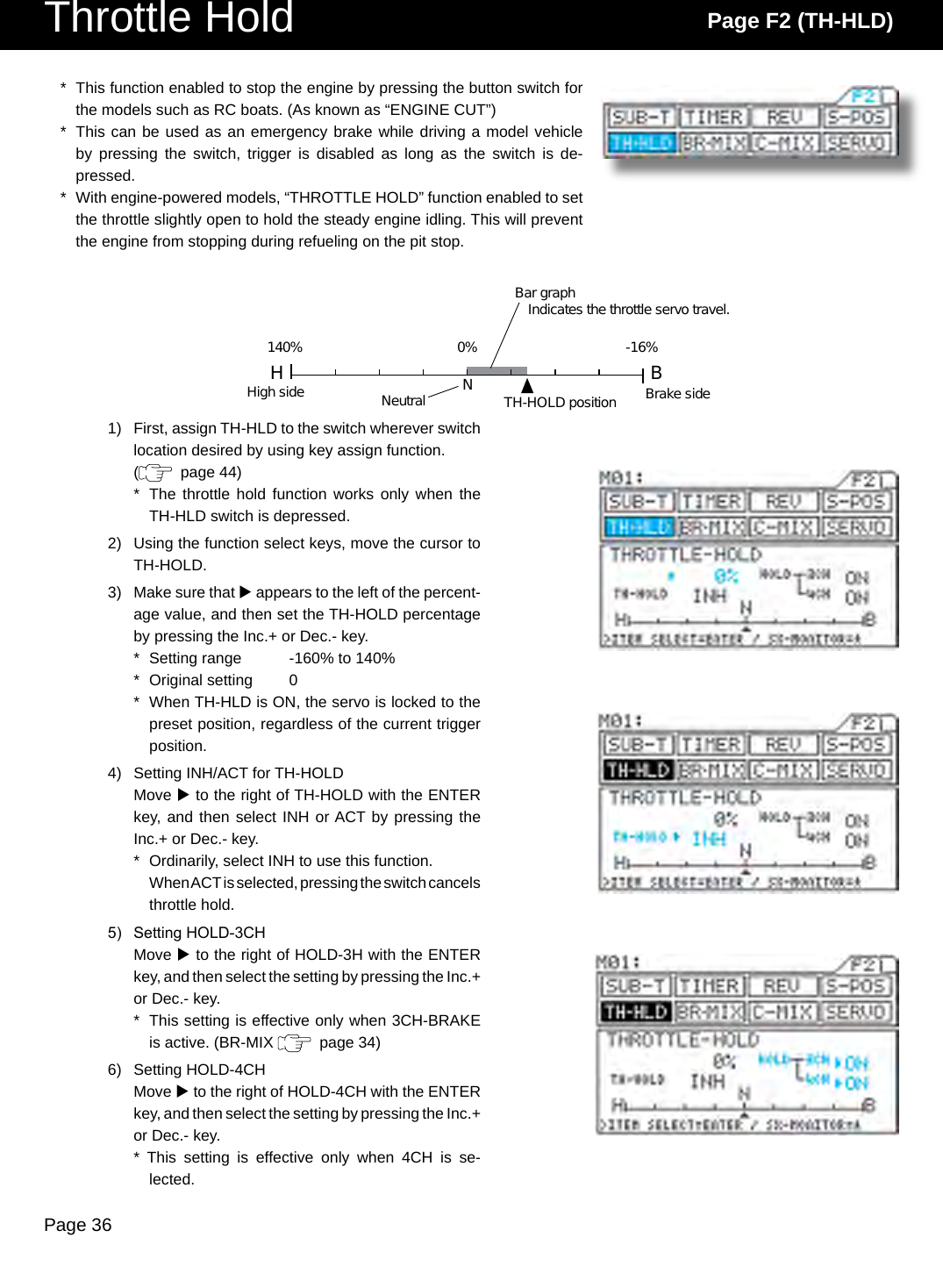
![Page 34SW3[REV] Servo ReversingTimer / Servo Reversing Page F2 (REV)With the standard conguration, the down timer switch is set to SW3. Pressing SW3 starts measurement.Each time you press SW3, the interval timer is restored to its preset value, and the countdown re-starts from that setting.ENDING MEASUREMENTEnd of measurement can be deactivated in two different ways.From the menu, by simultaneously pressing the Inc.+ and Dec.- key.By pressing and holding the switch for 3 seconds.IMPORTANT*When measurement ends, the timer’s ON/OFF status changes to OFF. To re-start the timer, turn in ON as described in step 2).*About the timer switchThe timer switch can be freely assigned to another switch using the key assign function. Set the switch to the position that is most suitable for you.6.This function is to switch the direction of servo operation, and is used in situations when controls such as the steering wheel or throttle operate in the opposite direction .Servo reversed can be individually adjusted for each of the 4 channels.Using the function select keys, move the cursor to [ST] in REV.Set the direction of servo operation by pressing the Inc.+ or Dec.- key.Setting range NOR/REVStandard setting NORMake settings for the other channels in the same manner.1.2.3.](https://usermanual.wiki/Airtronics/ATX037/User-Guide-545619-Page-34.png)
![Page 42Servo Page F2 (SERVO)* This function displays the output levels of the various channels in bar graph form, allowing you to monitor model operation in a virtual manner.* Using this feature while making function setting can make it easier to under-stand adjustments.* The graph can be displayed in the constant display area, allowing it to be viewed while making settings of other features. (Some menus cannot be displayed.)1) Using the function select keys, move the cursor to SERVO.2) Opening the constant display areaYou can open the constant display area from any menu by pressing the H key. Pressing the key a second time returns the display to normal.* Menus you can openF1 F2(1)D-RATE (1)SUB-T(2)EPA *(2)TIMER(3)EXP (3)REV(4)ARC (4)S-POS(5)SPEED (5)HOLD(6)ALB (6)BR-MIX(7)TR-CLL (7)SERVO * The graph cannot be displayed from the [LAP] menu.NOTE* REV operation is not reected in the servo monitor. Indication of the graph only shows the direction of the input control such as wheel and trigger movement.Example)BATT menuServo monitor displayConstant display areaBar graph display](https://usermanual.wiki/Airtronics/ATX037/User-Guide-545619-Page-42.png)
![Page 47Switch / Trim Assignment Page F3 ( -ASGN)* Functions and trim settings (adjustments to function settings) can be freely assigned to SW1-SW3, trimmers TRM1-TRM5, and the dial control on the transmitter.* Locations of switches and trimmers[SW] Key Assign Switch* ON/OFF control of various functions can be assigned to SW1-SW3, making it easy to use those functions during operation.* Up to three functions (FUNC1-FUNC3) can be assigned to a single switch, allowing all of those functions to be controlled at once.* Functions originally assigned to switches at the factory TRM1: Steering trim SW1: Starting position TRM2: Throttle trim SW2: Anti-lock braking TRM4: Dual rate SW3: Timer TRM5: End point adjust, brakeWhen the function is turned ON, character be displayed .Function status is also displayed in the constant display area.Here, LAP-T, INT-T, and DWP-T can all be turned ON/OFF together.Up to three functions can be assigned to a single switch.](https://usermanual.wiki/Airtronics/ATX037/User-Guide-545619-Page-47.png)
![Page 48[TRIM] Trim AssignmentFunction Menu screen Constant display area Factory defaultExponential steering EXP-ST EXSExponential throttle EXP-TH EXTAdjustable rate control, steering ARC-ST ARSAdjustable rate control, throttle ARC-TH ARTSpeed steering SPD-ST SPSSpeed braking SPD-BR SPBAnti-lock braking ALB ALB [SW2]Traction control TR-CTL TRCLap timerl LAP-T LAP [SW3]Interval timer INT-T INT [SW3]Down timer DWN-T DWN [SW3]Starting position S-POS SPO [SW1]Starting position, brake lock BR-LCK BRLThrottle hold TH-HLD HLDCompensation mixing 1 C-MIX1 CX1Compensation mixing 2 C-MIX2 CX21) Using the function select keys, move the cursor to [SW] in -ASGN.2) Using the H key or the ENTER keys, move u to the switch to be assigned, and then assign functions to the switch by pressing the Inc.+ or Dec.- key.* Assignable functions[TRIM] Key Assign Trim* Setting of function can be varies by using trimmers TRM1 to TRM5 and the dial.* The size of the STEP can be set and each setting width can be changed by pressing a key.* Functions can be freely assigned to any of 6 positions, allowing you to choose the controls that are best suited to your situation.* The values of function settings made using key assign trim can be displayed in the constant display area, allowing them to be conrmed from any menu.Settings also appearNumber of steps (size of change)Function settingStatus of settings is also displayed in the constant display area.](https://usermanual.wiki/Airtronics/ATX037/User-Guide-545619-Page-48.png)
![Page 491) Using the function select keys, move the cursor to [TRIM] in -ASGN.2) Function selectionUsing the H key or the ENTER keys, move u to the trimmer function to be selected, and then select a function by pressing the Inc.+ or Dec.- key.3) Setting the number of stepsUsing the H key or the ENTER keys, move u to the STEP for the trimmer you want to adjust, and then set the number of steps by pressing the Inc.+ or Dec.- key.* The number of steps determines the amount of trim that is applied for one click of the trimmer switch.* Selectable functions and step rangesFunction Menu screen Constant display area Factory defaultDual rate D/R 1 - 10 [SW4]End point adjustment, brake EPA-B 1 - 10 [SW5]Exponential steering EX-S 1 - 10Exponential throttle, high EX-H 1 - 10Exponential throttle, brake EX-B 1 - 10Adjustable rate control, steering rate AR-S-R 1 - 10Adjustable rate control, steering point AR-S-P 1 - 10Adjustable rate control, throttle high rate AR-H-R 1 - 10Adjustable rate control, throttle brake rate AR-B-R 1 - 10Adjustable rate control, throttle high point AR-H-P 1 - 10Adjustable rate control, throttle brake point AR-B-P 1 - 10Speed steering forward SP-S-F 1 - 10Speed steering return SP-S-R 1 - 10Speed steering point SP-S-P 1 - 10Speed brake forward SP-B-F 1 - 10Speed brake point SP-B-P 1 - 10Anti-lock braking point ALB-PT 1 - 10Anti-lock braking stroke ALB-ST 1 - 10Anti-lock braking lag ALB-LG 1 - 10Anti-lock braking speed ALB-SP 1 - 10Traction control, traction TRC 1 - 10Traction control, delay TRC-DY 1 - 10Traction control, point TRC-PT 1 - 10Starting position SPOS 1 - 10Throttle hold HLD 1 - 10Brake mixing delay, 2CH BM-2CH 1 - 10Brake mixing delay, 3CH BM-3CH 1 - 10Brake mixing delay, 4CH BM-4CH 1 - 10Compensation mixing 1, offset CX1-OF 1 - 10Compensation mixing 1, high CX1-Hi 1 - 10Compensation mixing 1, low CX1-Lo 1 - 10Compensation mixing 2, offset CX2-OF 1 - 10Compensation mixing 2, high CX2-Hi 1 - 10Compensation mixing 2, low CX2-Lo 1 - 10Steering trim TRM-S 1 - 10 [TRM1]Throttle trim TRM-T 1 - 10 [TRM2]Brake trim TRM-B 1 - 103CH (AUX) 3CH 1 - 10,20,50,100,200](https://usermanual.wiki/Airtronics/ATX037/User-Guide-545619-Page-49.png)
![Page 51Direct Servo Controller DSC CordUsing the DSC cable with DSC switch harness equipped on Gas powered type models1) Connect the supplied DSC cable to the DSC jack at the opposite side of the wheel of the M11.* The display appears.Using the DSC Switch Harness with an FET Speed Controller 1) Connect the supplied DSC cable to the DSC jack at the opposite side of the wheel of the M11.* The display appears.In order to check the model vehicle’s Linkage during the race or at the situation when the radio transmission is pro-hibited, such setting arrangement can be done by using the DSC cable.CAUTION- Never turn on the power switch on the transmitter while using the DSC harness. [ RF activate for radio transmission which may occur trouble to others. ]- When using the DSC cable, connect the power battery of the E/P car and/or connect the receiver battery to receiver for G/P models. - When using the DSC cable, be sure that the transmitter battery is installed.- After using the DSC cable, be sure to disconnect the DSC cable at both end.(* Prevent from possible risk from other radio transmission, remove the receiver crystal.)2) Connect the DSC Cable’s male connector to the Battery/DSC channel on the receiver.3) Turn on the Display switch at M11 thence turn on the Power at ESC ‘s switch harness.4) Ready for DSC operation.(* Prevent from possible risk from other radio transmission, remove the receiver crystal.)2) Connect the DSC cable (female connector) to the charging connector (male) on the DSC switch harness.3) Turn on the Display switch at M11 thence turn on the power at DSC switch harness.](https://usermanual.wiki/Airtronics/ATX037/User-Guide-545619-Page-51.png)