Airtronics ATX037 Transmitter and Module for Radio Control User Manual
Airtronics Inc Transmitter and Module for Radio Control Users Manual
Users Manual

Page 2
These instructions are intended to asquaint you with the
many unique feachures of the state of the art equipment.
Please read them carefully so that you may obtain maxi-
mum success and enjoyment from its operation.
We ask that yo pay particular attention to the design of the
transmitter. Notice that it has been human engineered for
the most natrual and precise control of your choice of oper-
ating cars, tucks and boats.
Be certain to read all the material in this manual.
SAFETY FIRST FOR YOURSELF, FOR OTHERS AND
FOR YOUR EQUIPMENT
“SAFETY FIRST” is more than just a slogan when operating
radio controlled models.
FOR YOUR SAFETY:
AT THE TRACK, LAKE or anywhere other people are using
radio control equipment that you DO NOT turn on your
transmitter untill you know your frequance is clear. YOU
MUST NOT TURN ON YOUR TRANSMITTER WHEN
SOMEONE ELSE IS USING THE SAME FREQUANCY
YOUR TRANSMITTER IS ON. Only one person can use a
given frequancy at one time.
Observe all the rules at the eld or track you are at.
FREQUANCY IDENTIFICATION AND DISPLAY SYSTEM
The Federal Communications (F.C.C.) species radio
frequancies in MHz units. For convenience, the frequan-
cies are designed by CHANNEL numbers and or by colored
ags. Numbered channel markers on the transmitter identify
the specic channel. A yellow wind streamer identis a 75
MHz transmitter.
This equipment has been designed for 27 or 75 MHz only
and can only be used for surface use and can not be used
for any aircraft use at all.
WARING: The 75 MHz frequancies allocated for model
radio control use are exclusive; however, they are in close
proximity to other types of radio usage in certain areas. Be-
fore operating your model, check with the FCC regional of-
ce in your area to determine wheather there is a potential
danger or interference from other radio users. The FCC of-
ces are usually listed in your telephone directory under the
section designated to United States Government Ofces.
When dealing with the FCC, you should state the type of
activity you are involved in (i.e., radio control of model boats
or cars) and inquire if there are any commerical RF trans-
mitters on or close to your frequancy in Megahertz (MHz).
Do not use R/C channel numbers since the FCC will not be
able to correlate them with actual frequancy. “Outside” radio
interferance may cause you to lose control of your model,
possibly resulting in injury to yourself or others, or property.
SO REMEMBER:
DO NOT OPERATE your transmitter at the track or lake, untill
you are certain your frequancy is clear.
DISPLAY your frequancy ag and channel identication on the
antenna of your transmitter.
REMENBER that ags do not usually state the frequancy on
them and sometimes the colors are hard to distingguish. If you
have an eyesight limitation or defect such as color blindness,
double check the frequancy ag designations with someone
else.
TURN YOUR TRANSMITTER ON ONLY IF YOUR FREQUAN-
CY IS CLEAR.
WARING: your model will go out of control and may cause
some series injury or damage if someone else turns on a trans-
mitter on your frequancy while you are operating your model.
RESPECT ALL THE RULES of the operating site.
AT ANY TIME during the operation of your model, should you
sense, feel or observe any erratic operation or abnormality,
end your operation as quickly and safely as possible. DO NOT
operate again until you are certain the problem has been cor-
rected. TAKE NO CHANCES.
Safety

Page 3
Contents
Safety
Before using the M11
NiCd Batteries
Changing Bands
Transmitter Features and Controls
Key Pad menu buttons
Function Pages
Battery / Operation Timer
Dual Rate Steering
End Point Adjustment
Exponential
Adjustable Rate Control
Speed
Anti-Lock Braking
Traction Control
Model
Sub Trim
Timer
Servo Reversing
Start Position
Throttle Hold
Brake Mixing
C-Mixing
Servo
Setup
Audio Signal Sound
Switch / Trim Assignment
User Name
Direct Servo Controller
Receiver Connections
Troubleshooting
F1, F2, F3
BATT
D-RATE
EPA
EXP
ARC
SPEED
ALB
TR-CTL
MODEL
SUB-T
TIMER
REV
S-POS
TH-HLD
BR-MIX
C-MIX
SERVO
SET-UP
SIGNL
E-ASGN
USER
DSC
2
4-5
6
7
8-9
10
11
12
13
14-15-16-17
18-19
20-21
22-23
24
25-26
27-28
29
30-31-32-33-34
34
35
36
37-38
39-40-41
42
43-44
45-46
47-48-49
50
51
52
53
Topic Page
Page 4
Before Using the M11
Driving Position Adjustments
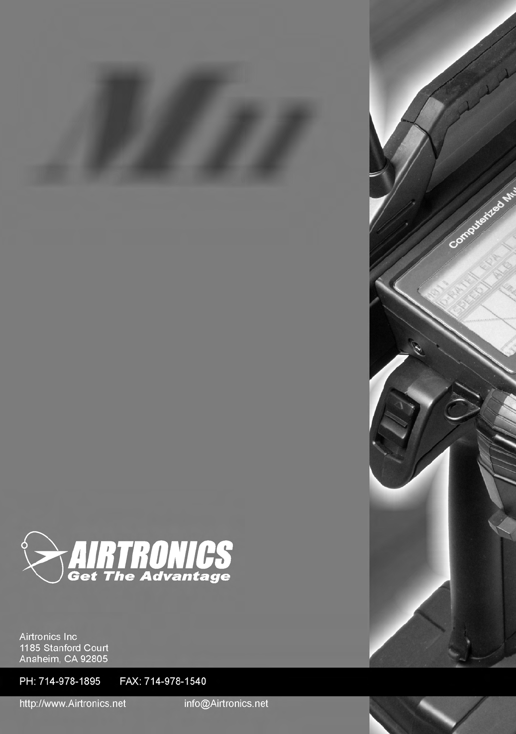
Steering Wheel Tension
The steering spring tension can be adjusted using a 1.5
mm hex wrench as shown in the photo. Steering spring
tension will increase as you tighten the hex bolt. Note: The
spring tension is factory set at the lowest (softest) position.
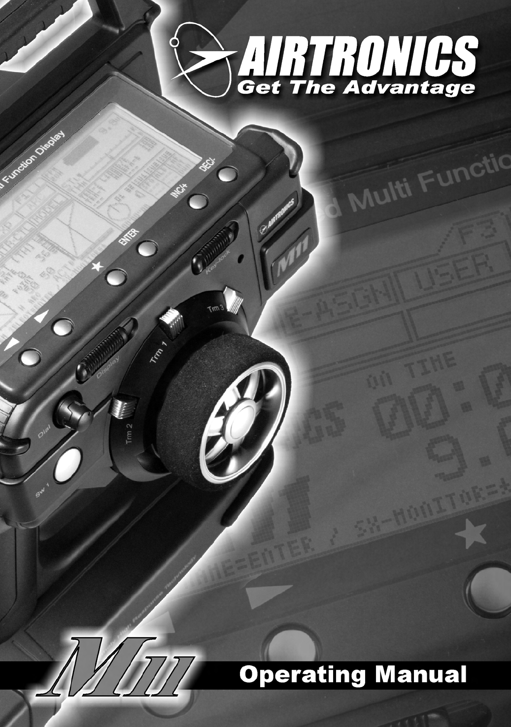
Driving Position
1. Remove the 4mm hex socket head cap screws on
each side of the transmitter using a 3mm hex wrench.
2. Detach the grip downward from the upper transmitter
unit. Be careful to avoid damaging the lead wires that
are connected on both units.
3. There are four (4) Phillips screws holding each side of
the grip bracket. Remove the screws and reset the
bracket screw hole at the lower screw hole. This sets the
racket to the higher height position. Note: The grip
bracket is factory set to the lower height position.
4. After resetting the driving position, retighten the grip
bracket screws. Attach the upper part of the transmitter
unit into position with two (2) 4mm hex socket head cap
screws and a 3mm hex wrench.
Throttle Trigger Tension
1. Remove the 4mm hex socket head cap screws on each
side of the transmitter using a 3mm hex wrench.
2. Detach the grip downward from the upper transmitter
unit. Be careful to avoid damaging the lead wires that are
connected on both units.
3. Adjust the throttle trigger spring tension using a 1.5 mm
hex driver. Location of the 1.5mm hex bolt is shown in
the photo. Throttle trigger spring tension increases as
you tighten the hex bolt. Note: The spring tension is
factory set to the lowest (softest) position.
4. After resetting the throttle trigger spring tension, align the
upper transmitter unit into place. Tighten using the 3mm
hex wrench and two (2) 4mm hex socket head cap
screws per side.
Every effort has been made to provide optimum transmitter weight balance on your M11. The wheel and trigger are placed on the
same axis, permitting you to focus on steering and throttle control. The driving position and steering/throttle tension are adjustable
to maximize driving precision.
Page 5
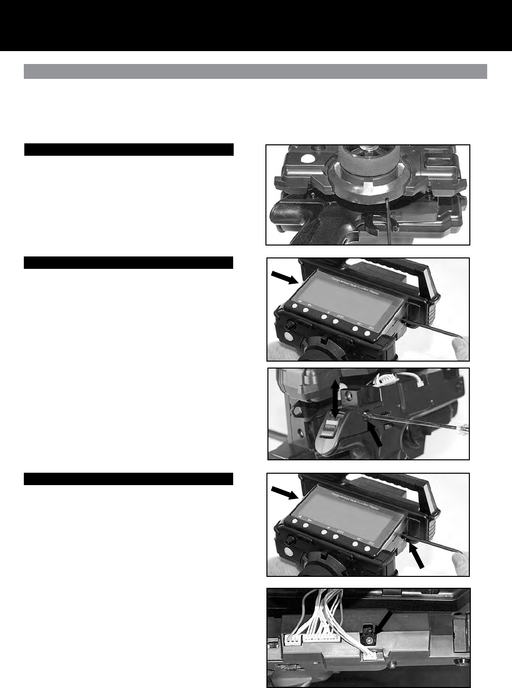
Trim Position
Trim position may be adjusted (5 positions) by rotating the
trimmer unit.
1. Remove the 4mm hex socket head cap screws on each
side of the transmitter by using 3mm hex wrench.
2. Detach the grip downward from the upper transmitter
unit. Be careful to avoid damaging the lead wires that
are connected on both units.
3. Remove the three hex socket head cap screws (M2.6)
from the backside of the trimmer unit (i.e. behind the
steering wheel as shown on the photo.)
4. Rotate the trimmer unit to the desired position. Trim
position may be selected from ve (5) positions. Set the
trimmer unit at optimum trim position. After selecting the
position, retighten the hex socket head cap screws
(M2.6).
5. After resetting the trimmer position, attach the upper
transmitter unit back into place. Tighten using a 3mm
hex wrench and two (2) 4mm hex socket head cap
screws per side.
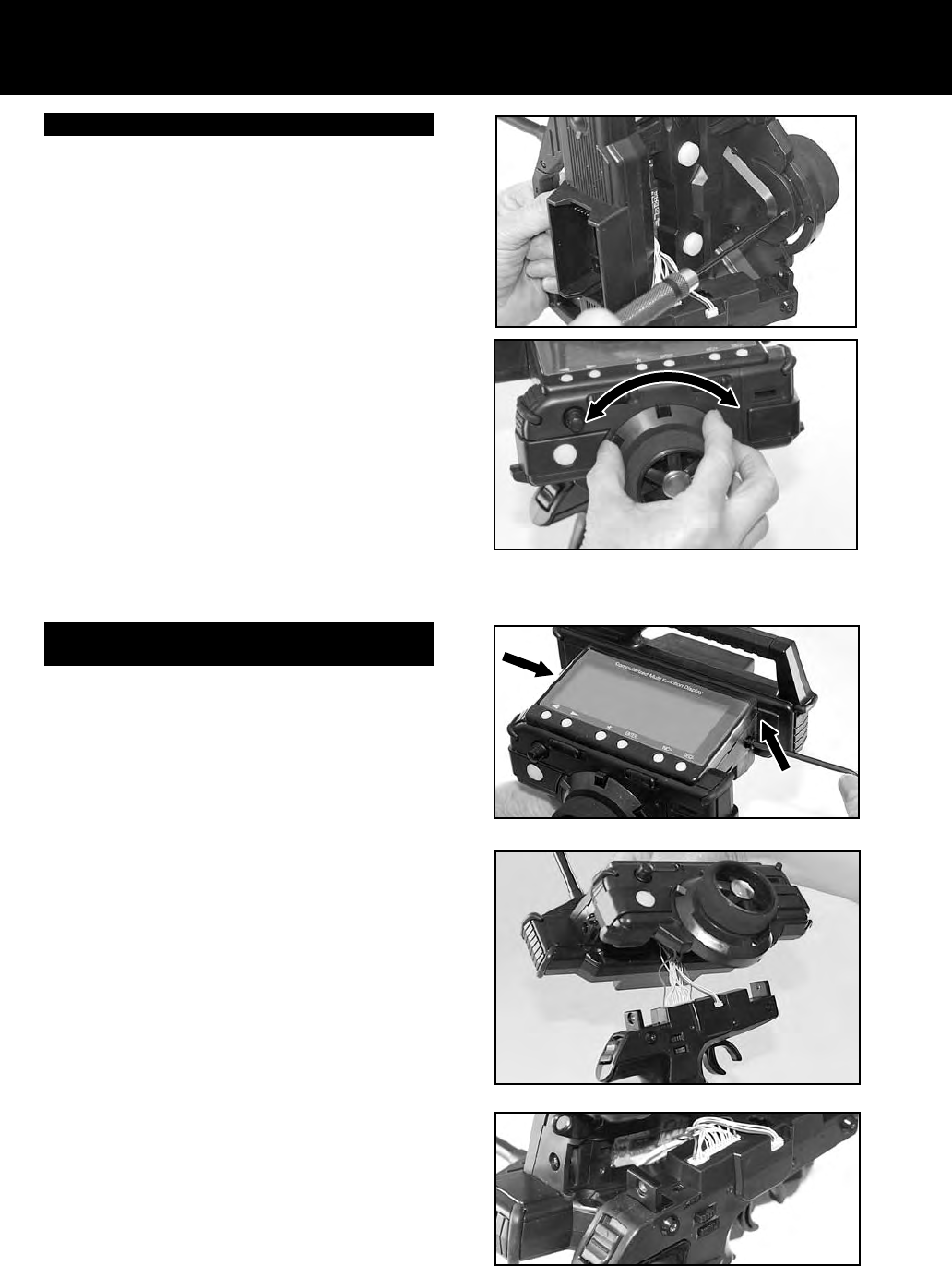
Switching Right Driving position to Left Driving
Position (Dominant hand)
In order to change to a left handed driving position, rotate
the grip as follows:
1. Remove the 4mm hex socket head cap screws on each
side of the transmitter using a 3mm hex wrench.
2. Detach the grip downward from the upper transmitter
unit. Be careful to avoid damaging the lead wires that
are connected on both units.
3. Set the Left/Right selector switch to L. (As shown on the
photo)
4. Rotate the grip by 180 degrees.
5. After rotating the grip, align the upper transmitter unit into
place. Tighten using a 3mm hex wrench and two (2)
4mm
hex socket head cap screws per side.
Page 6
NiCd Batteries
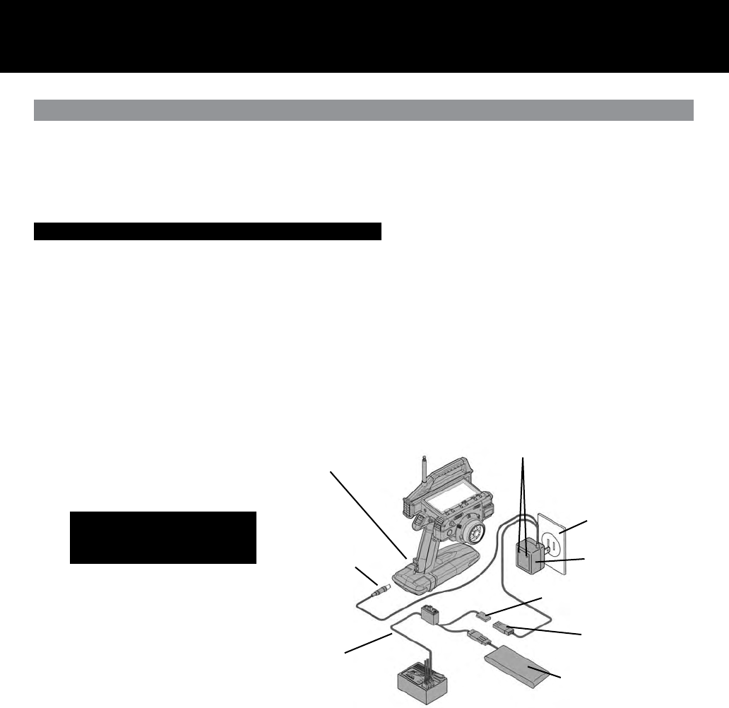
Safety Precautions When Charging A Nicd Battery. (Optional part)
Round TX Plug
Charging Indicator Lights
Charger
USA 110 volts
Charging Connector
NOTE: The receiver plug can not be
used to charge the transmitter NiCd
battery pack when the battery pack is
out side the transmitter.
Flat RX Plug ONLY
Switch harness with DSC Optional NiCd Battery
4.8 or 6.0 volts
Optional NiCd Battery Installed
Part number 95046Z
CAUTION!
* Please read the charging procedures listed below to ensure safe and correct use of your NiCd battery.
* The battery is not charged when purchased. It is necessary to charge the battery before operation.
* Before charging NiCd batteries, double check power switches are in the off position on the transmitter and/or receiver.
Charging the Transmitter/Receiver NiCd Batteries.
1. Connect the supplied charger to AC 120 V power outlet.
2. Charging the transmitter NiCd battery: Connect the round charger jack to the transmitter-charging outlet.
3. Charging the receiver NiCd battery: Connect the square plug on the charger to the connector on the receiver (for an engine
powered model) NiCd battery, or to the charging connector on the switch harness.
* Make sure that the charging indicator LED light is on.
Charging a battery for the specied period may not result in a full charge if you have a new battery or have not used the battery for
an extended period of time. In this case, you can activate the battery for use by running it through two or three charge cycles.
WARNING: To prevent serious personal injury and/or damage to property, you must observe the following precautions
when handling NiCd batteries.
Incorrect use can result in electrolyte spills, overheating, and bursting.
* Use only the supplied charger for charging your niCd batteries and never charge for more than the specied amount of time.
* Overcharging damages a battery and can result in overheating, bursting, and electrolyte spillage. This may cause personal injury
and/or to property (i.e. burns, re, or damage to the eyes.)
* Do not plug the supplied charger (95033Z) into anything other than AC 120 V power outlet. Plugging the charger into anything
other than AC120 V outlet may result in smoking, sparks, or re.
* When connecting the charger connector to the receiver NiCd battery or switch harness, be careful to avoid reversing the polarity
or shorting the connector.
* Do not dispose of the battery in any re or allow it to overheat.
* Do not short-circuit the positive terminal or the negative terminals with wire or any other object.
* Do not remove the outer tube. This is for protection and prevents scratches or other damage.
* Do not throw the battery or abuse in any manner.
Page 7
Changing Bands
WARNING
Use only genuine Airtronics FM Crystals.
Use of crystals, other than specied, may result in frequency
errors and possible runaway operation.
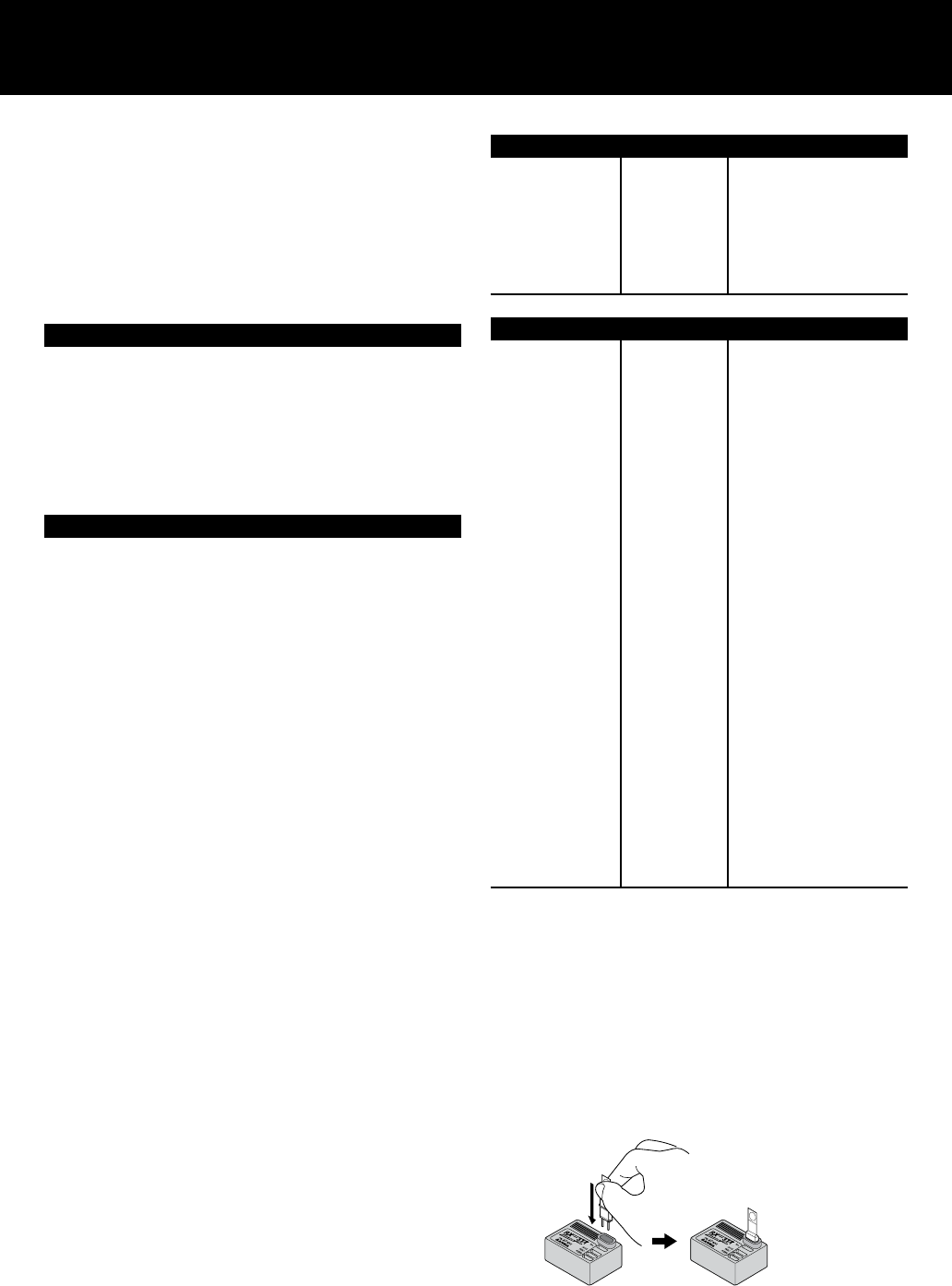
Replacing the Transmitter Crystal
1. Remove the crystal cap from the TX module, pull out the
crystal, and insert the crystal for the desired frequency.
2. Replacement of the TX module is necessary in order to
switch between the 27 MHz and 75 MHz bands.
3. When removing the TX module, pull it out toward the front
while pressing the side tabs inward.
Replacing the Receiver Crystal
1. Pull out the crystal, install the silicone ring on the replaced
crystal and plug it into the receiver.
2. Receiver replacement is necessary in order to switch
between the 27 MHz and 75 MHz bands.
NOTE
* The 93327 or 93375 TX modules are for use exclusively with
the M11. They are not compatible with any other TX modules.
* Crystals are marked for use with transmitters (TX) or receivers
(RX). Be careful to use them in the correct module or
receiver.
* Make sure that the TX module is securely installed. Improper
installation can result in damage to the equipment. If the
module does not install smoothly, inspect it for possible
damage.
* When changing bands, you must replace the band plate on
the transmitter.
* The TX module will become warm during operation; this is
normal and is not a problem.
* On the TX module, be sure to install the silicone ring on the
crystal cap.
* On the receiver crystal, be sure to install the silicone ring for
micro receivers.
The special silicone compound protects the crystal from shock
and vibration.
* List of Bands and Frequencies Used
26.995 MHz
27.045 MHz
27.095 MHz
27.145 MHz
27.195 MHz
27.255 MHz
1
2
3
4
5
6
27 MHz band
Channel # Frequency
75 MHz band
Channel # Frequency
61
62
63
64
65
66
67
68
69
70
71
72
73
74
75
76
77
78
79
80
81
82
83
84
85
86
87
88
89
90
75.410MHZ
75.430MHZ
75.450MHZ
75.470MHZ
75.490MHZ
75.510MHZ
75.530MHZ
75.550MHZ
75.570MHZ
75.590MHZ
75.610MHZ
75.630MHZ
75.650MHZ
75.670MHZ
75.690MHZ
75.710MHZ
75.730MHZ
75.750MHZ
75.770MHZ
75.790MHZ
75.810MHZ
75.830MHZ
75.850MHZ
75.870MHZ
75.890MHZ
75.910MHZ
75.930MHZ
75.950MHZ
75.970MHZ
75.990MHZ
Handling of Receiver Crystals
With receiver crystals, be sure to install the silicone ring. This
ring contains special silicone compound that protects crystals
from shock, vibration and dust.
When installing receiver crystals in the receiver, press the ring
with your thumb and forenger to prevent it from slipping off.
When installing the crystal, make sure that the top of the
silicone ring is level with the top of the receiver case. If the ring
protrudes outward, press it into the case.
Page 8
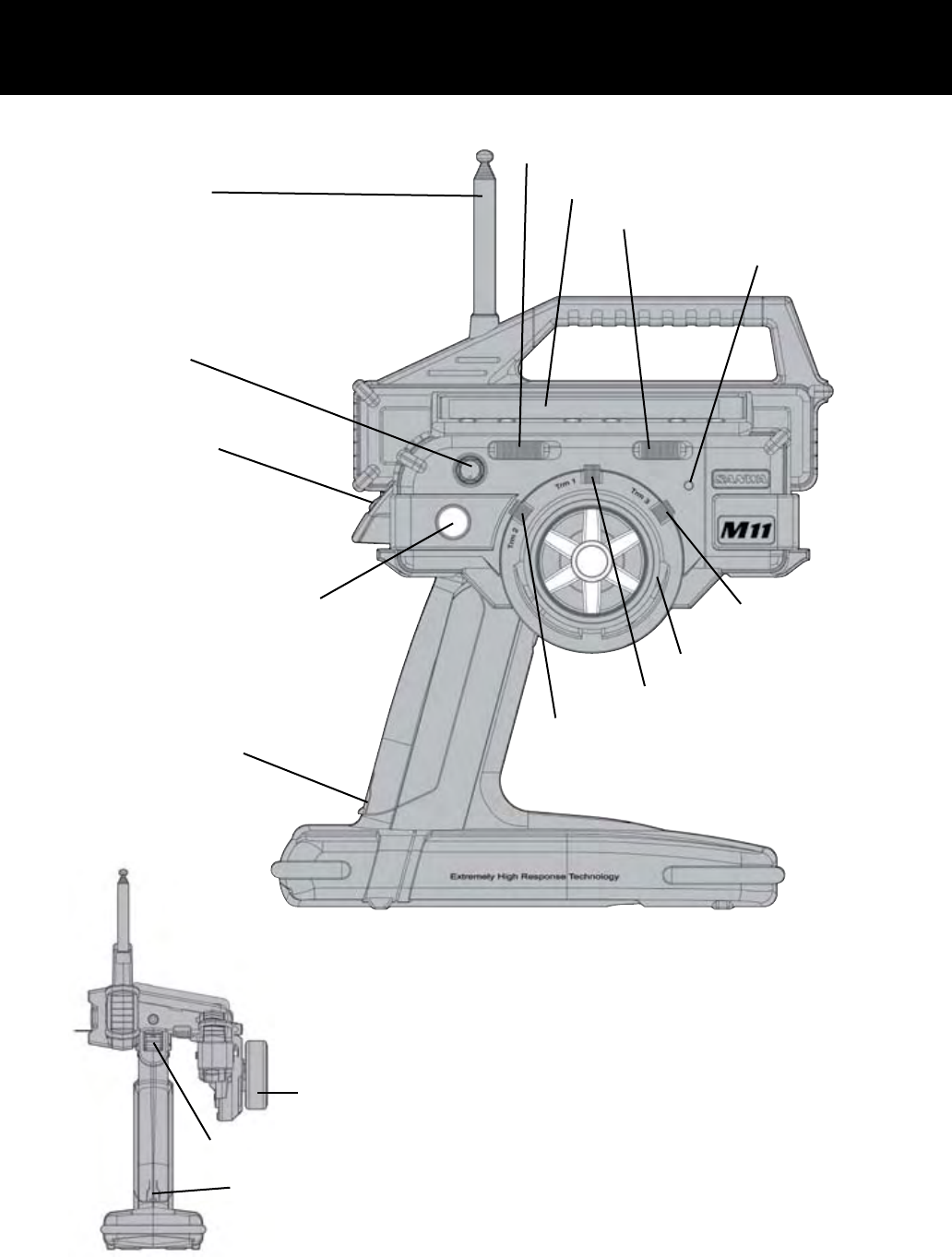
Transmitter Features and Controls
Display Switch
Display Panel
Key-Lock Switch
Power Indicator Light
Trim Control (TRM3)
Steering Wheel
Trim Control (TRM2)
Trim Control (TRM1)
Charging Jack
Push Button Switch (SW1)
Power Switch
Dial Knob
Antenna
Charging Jack
Power Switch
Steering Wheel
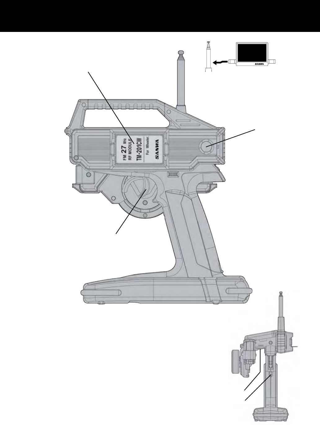
Page 9
S L
03
27.025MHz
* How to use the band plate
Band plate
Affix the band plate to the
reverse side in the same
manner.
TX Module
Direct Servo Control Jack (DSC)
Throttle Trigger
Push Button Switch (SW2)
Push Button Switch (SW3)
Page 10
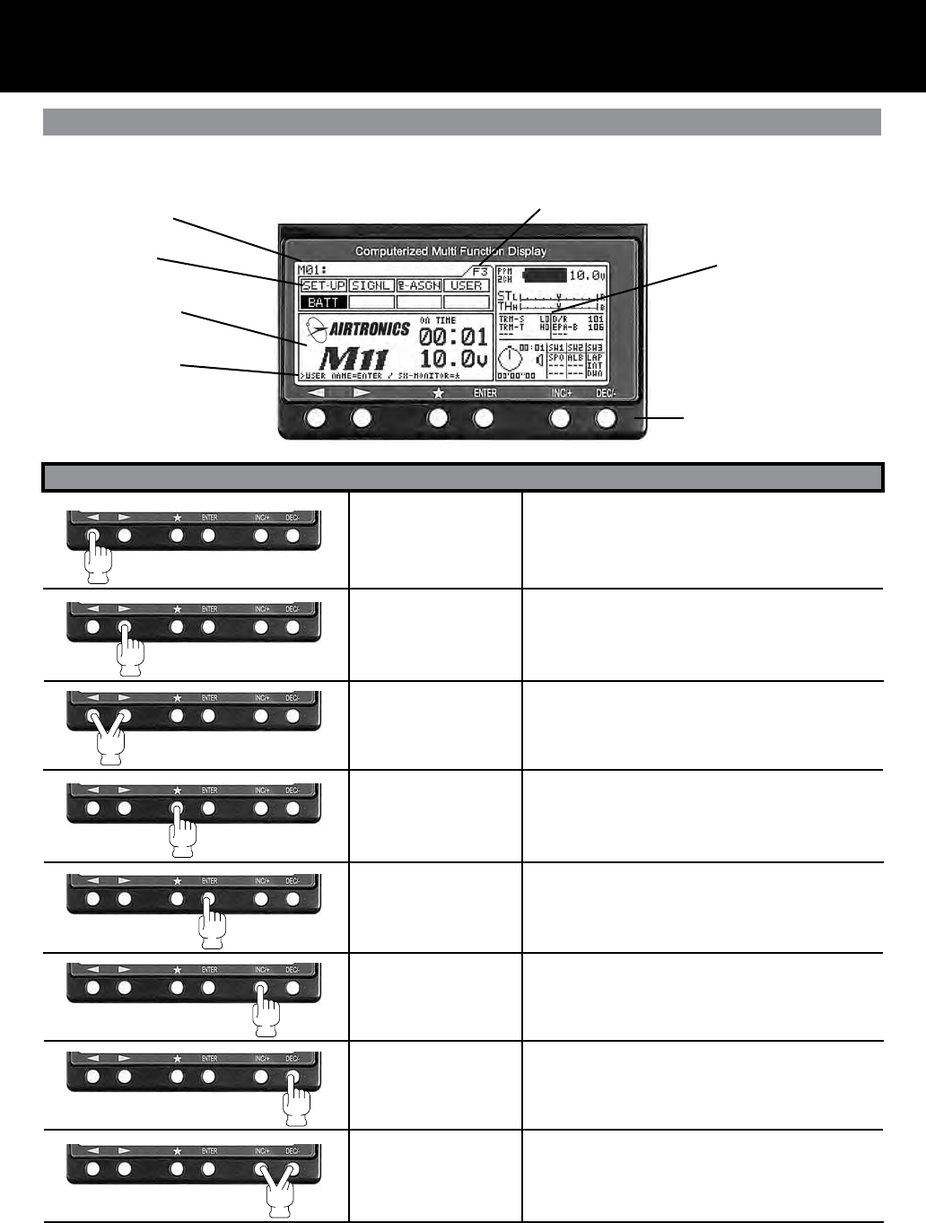
Key Pad Menu Buttons
HELP Display Area
Using the Key Pad Menu Buttons
Function select Key
(Left)
Function select Key
(Right)
Function Page select
Key sequence
Scroll Key
Enter Key
INC+ Key
(Increase)
DEC- Key
(Decrease)
INC+ and DEC-
(Reset)
Moves the Menu Function cursor left to the previous
(backwards) menu function.
Moves the Menu Function cursor right to the next
(forward) menu function.
Pressing down on both keys will scroll through func-
tion pages in order. F1, F2 and F3.
The menu function cursor will highlight the rst func-
tion on that page.
Will move the menu key backwards in the program-
ming area. Also used in the HELP display area.
Programming Area
Menu Function
Model Number
Function Page
Information Area
Key Pad
é
Will move the menu key forward in the programming
area. Also used in the HELP display area.
Increases number values in programming area.
Scrolls up selection list.
Decreases number values in programming area.
Scrolls down selection list.
Resets selection to factory default setting.
Key Name Function
The M11 has 6 keys for menu operations. You will nd the use of the 6 keys summarized below.
Page 11
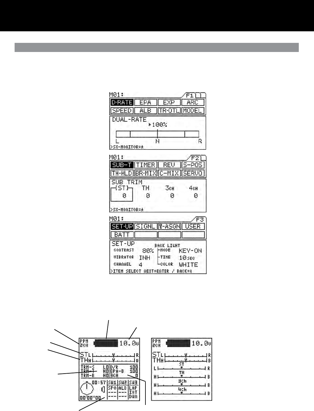
Menu Function Pages / Information Area
Number of Channels (2 or 4)
Steering Trim
Throttle Trim
Timer and Switch Status
Battery Remaining
Battery Voltage
Trm 1, Trm 2, Trm 3
Feature display and set-
tings
Steering Dual Rate, Brake EPA and 3CH settings
Optional information screen can be
changed using the key.
Note: can only be changed when the
help screen shows SX-MONITOR=*
é
Function Pages
Function Menu Page 1
Function Menu Page 2
Function Menu Page 3
The functions of the M11 span three pages, F1 to F3, and can be selected directly using just the < and > keys. The rst function on
successive pages can be easily displayed in the sequence F1 > F2 > F3 > F1 . . . by pressing the < and > keys at the same time.
A constant display area is provided on the right side of the screen. This makes it possible to determine, at a glance, the current set-
ting status of various functions from any menu screen. Further, you can display the servo monitor screen by pressing the star key.
Page 12
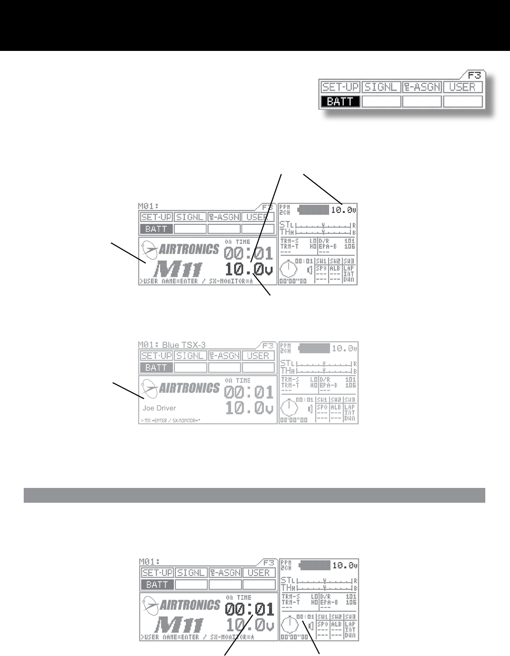
Battery / Operation Timer Page F3 (BATT)
Battery voltage indicator
The transmitter battery voltage can be seen in two separate windows
and measures 0.01 of a volt.
1. BATT Menu
2. Information Menu
}
NOTE: This area of the
information screen is not
programmable and will stay
on all the time.
When the transmitter battery runs down to 9.1 volts, the transmitter will start beeping and vibrating if the vibration feature is on and
will continue every 30 seconds. When this happens, promptly stop operation and charge or replace the transmitter batteries.
Will start blinking if battery reaches 9.1 volts or below.
M11 Screen
User Name Screen
In the BATT menu, you can press the
ENTER key to switch between the user
and M11 screens.
Operating Timer
The operating timer is a up timer that records the time the transmitter has been on in hours and minutes. This timer can be reset
to 00:00 by pressing both the (INC/+) (DEC/-) keys at the same time. By resetting the Operating timer after you have charged or
replaced the transmitter battery will give you the amount of time the current battery has been in use.
Operation Timer in BATT screen Operation Timer on all the time.
Page 13
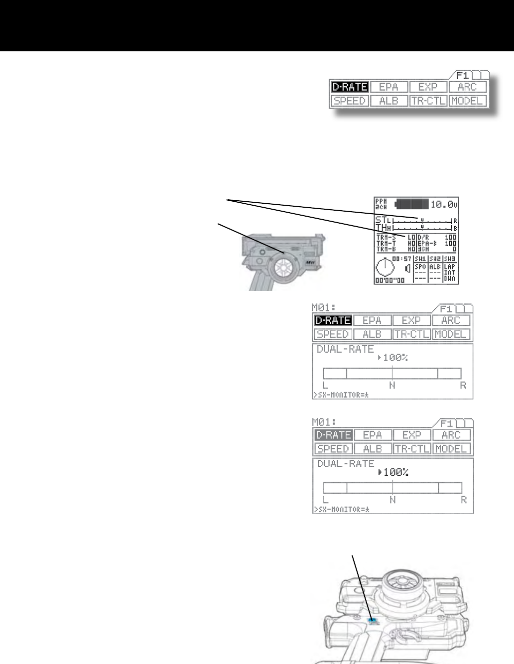
Dual Rate Steering Page F1 (D-RATE)
Trm 4 (top)
Dual Rate is used to change the amount of servo movement compared to the amount of movement with the steering wheel. Increas-
ing the amount of dual rate will make the steering more sensitive or feel faster and decreasing the dual rate will make the steering
more insensitive or feel slower.
When setting up a new car or truck, follow the directions below to properly setup your steering dual rate.
Press the function select key to move the cursor to (D-RATE). As you
move the steering wheel from side to side, you can set the bar graph
move to the dual rate limit lines. Default setting is 100%.
Adjust the dual rate by pressing the INC+ or DEC- keys to increase
or decrease dual rate amount. At this time, set the dual rate to 125%.
This will increase the servo movement my 25% in both left and right
directions.
NOTE: Pressing both the INC and DEC keys together will set the dual
rate to the default setting of 100%.
After the dual rate has been set, adjust the independent left and right
end points using the EPA feature.
1. Set the digital steering trim to “0” by using (Trm 1). You can see when the trim
reaches center by viewing one or both screens.
Steering trim factory default location: (Trm 1)
2.
Attach the steering linkage to the servo arm as the car manufacturer
recommends. Be sure to have all steering linkage, trim and servo arm
as close to center as possible. Doing so will cut out a lot of steering
problems later.
Now move the steering wheel left and right to full. If your steering
binds at both ends, this means you have to much movement coming
from the servo. Use the dual rate to reduce or increase the amont of
steerings to reach the steering stops.
3.
4.

Page 14
End Point Adjustment Page F1 (EPA)
[ST] Steering End Point Adjustment
End point adjustment is used to adjust the proper amount of servo movement on the model’s steering angle to steer left and right
and/or adjust the carburetor throttle arm stroke, the high point of an ESC and brake stroke.
While the M11 is set for 4 channels, this EPA function is also adjustable for 3rd BRAKE or AUX Channel) and for 4th channel of
brake.
A model’s turning radius can differ from left to right because of variations in
linkage, suspension balance, tire diameter or weight distribution of the vehicle.
In such cases, the left and right servo steering angle is adjustable.
Before making the end point adjustment, you must set the servo to the neutral
position. To nd the center position, adjust the servo horn to approximately
center position, and then make ne adjustments using the sub-trim.
Next, press the function select key and move the cursor to [ST] in EPA.
To set the steering end point on the right side, turn the steering wheel fully
clockwise and depress the Inc.+ or Dec.- key. To set the left steering end point,
do the same with the steering wheel turned fully counterclockwise.
Setting range 0% to 150%
Default setting 100%
1.
2.
3.
IMPORTANT
Note: Setting the steering dual rate and steering end points excessively high may cause a dead point on the servo, resulting in
improper operation.
Page 15
Trm 5 (bottom)
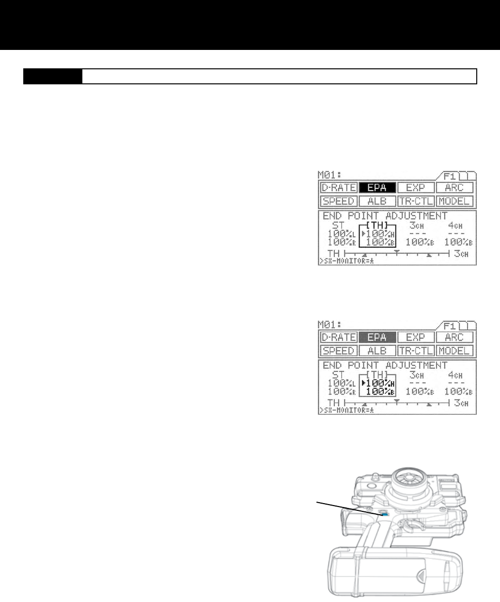
[TH] Throttle End Point Adjustment
Press the function select key and move the cursor to [TH] in EPA.
To adjust the high end of throttle movement on a gas -powered car, pull the
throttle trigger all the way to the high side and adjust by pressing the Inc.+
or Dec.- key.
To adjust the brake side, push the throttle trigger all the way to the brake
side and adjust by pressing the Inc.+ or Dec.- key.
With an ESC, the high side and brake side are both ordinarily set to 100%
and then the high point and brake point are set on the ESC.
(Setting procedures may vary depending on the type of ESC.)
Setting range 0% to 140%
Brake side 0% to 160%
Standard setting 100%
Test run your vehicle to arrange the brake adjustment by using TRM5 switch
on the grip. You can vary the setting at EPA-B by adjusting with TRM5.
While the M11 is set for 4 channels, setting value may vary at the same
time.
Throttle end point adjustment is used to adjust the carburetor stroke, high point of an ESC, or the brake stroke.
1.
2.
3.
NOTE
With gas-powered model linkage, if the linkage stroke is set too wide, the servo
may lock up. This results in fatal damage and may cause the vehicle to runaway.
TIP
Brake adjustment TR5 switch can be assignable with other trim switches.
Page 16
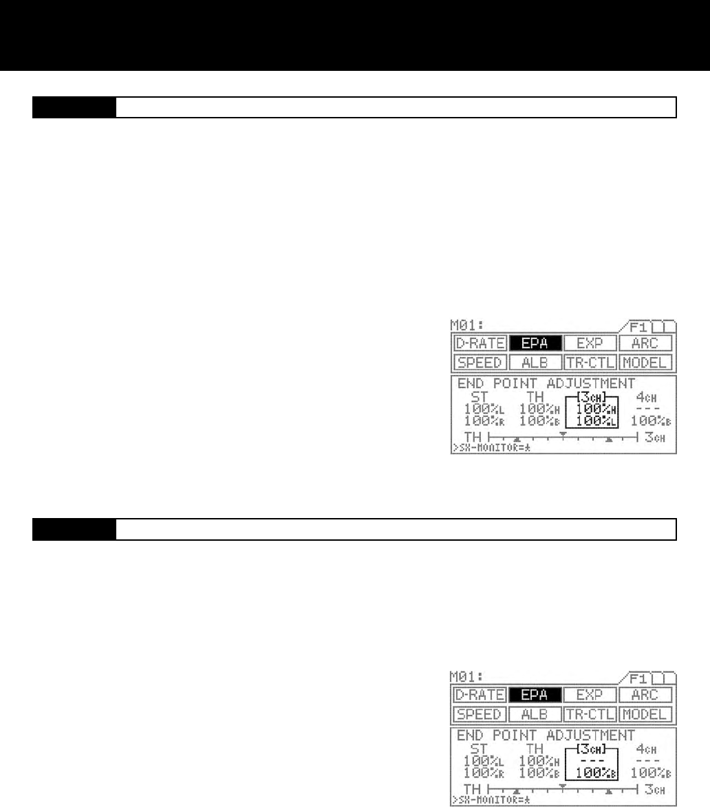
[3ch] AUX End Point Adjustment ( with 3ch - BRAKE INH )
NOTE: I order to set any functions for AUX 3 and AUX 4, you must rst set the channel setting from 2 to 4 channel. To change from
2 to 4 channel, go to the F3 page on the transmitter, move the function menu cursor to SET-Up and change the channel number in
the programming area on the transmitter screen.
[3ch] 3CH-BRAKE End Point Adjustment ( with 3ch - BRAKE ACT )
1.
The AUX channel can be used for functions such as needle control or for
other uses. The end point adjustment allows ne adjustment of the maxi-
mum servo travel. Further, the high end point and low end point can be set
independently, which provides great exibility of adjustment.
Be sure that channel 4 is selected in the set-up menu and that 3CH-BRAKE
is set to INH in the BR-MIX menu. It is essential to set the M11 as “4channel”
in order to use these functions.
Press the function select key and move the cursor to [3ch] in EPA.
To select the low side AUX setting, turn the dial counterclockwise and de-
press the Inc.+ or Dec.- key. To select the high side setting, do the same after
turning the dial clockwise.
Setting range 0% to 150%
Standard setting 100%
TIP
The standard setting of the AUX key assign trim function is on DIAL. * This
dial can be assignable with other trim switches such as TRM 1 to TRM5.
2.
3.
With 4-channel setting
Make sure that the channel 4 is selected in the set-up menu and that 3CH-
BRAKE is set to ACT in the BR-MIX menu. It is essential to set this function
in order to activate this set up menu.
Press the function select key and move the cursor to [3ch] in EPA.
Push the throttle trigger all the way to the brake side and then adjust by
pressing the Inc.+ or Dec.- key.
Setting range 0% to 160%
Standard setting 100%
If it is necessary to arrange the EPA brake adjustment during the operation of
the vehicle, use trimmer TRM5 on the grip.
When using 3rd channel as the additional BRAKE channel, the end point adjustment can be separately set from the other BRAKE
channel.
1.
2.
3.
IMPORTANT
* Since this channel is exclusively for braking purpose, setting of EPA covers only at the BRAKE side.
4.
Page 17
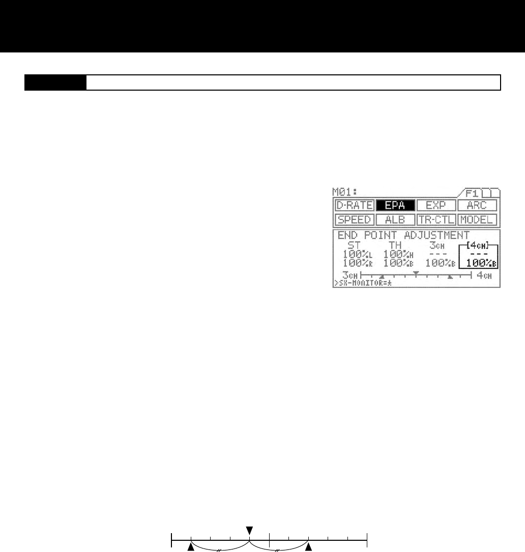
[4ch] 4CH - BRAKE End Point Adjustment
TH 3CH
EPA of TH EPA of 3ch
1. Be sure that the channel 4 is selected in the set-up menu. It is essential to
set this function in order to activate this set up menu.
Press the function select key and move the cursor to [4ch] in EPA.
Push the throttle trigger all the way to the brake side and then adjust by
pressing the Inc.+ or Dec.- key.
Setting range 0% to 160%
Standard setting 100%
If it is necessary to arrange the EPA brake adjustment, during the opera-
tion of the vehicle, use trimmer TRM5 on the grip.
The 4th channel is exclusively for braking purpose only. When using the 4th channel as the additional BRAKE channel, end point
adjustment can be separately set from the other BRAKE channel.
IMPORTANT
Since this channel is exclusively for braking purpose, setting of EPA covers only at the BRAKE side.
TIP
Balance bar graph
The bar graph appearing at the bottom of the screen is useful when setting the brake on more than two channels.
The graph indicates the center position of two EPA values. Use it as a guide to nding a good brake balance. The lower triangles in
the graph indicate the respective EPA values.
When 3CH-BRAKE is set to ACT, the ENTER key switches the balance display between TH-3CH and 3CH-4CH. When 3CH-
BRAKE is set to INH, the bar graph shows only the TH-4CH balance.
3.
2.
Page 18
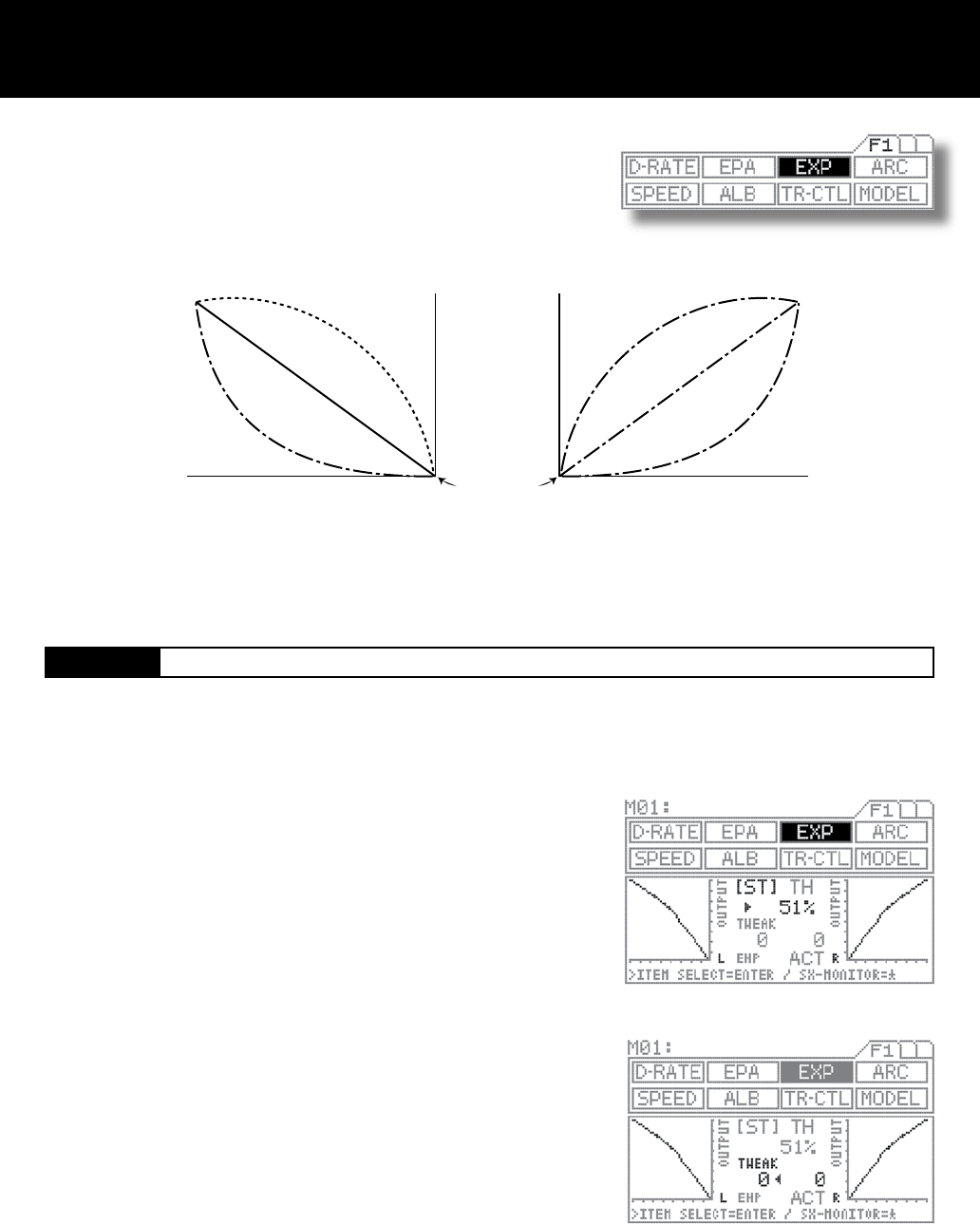
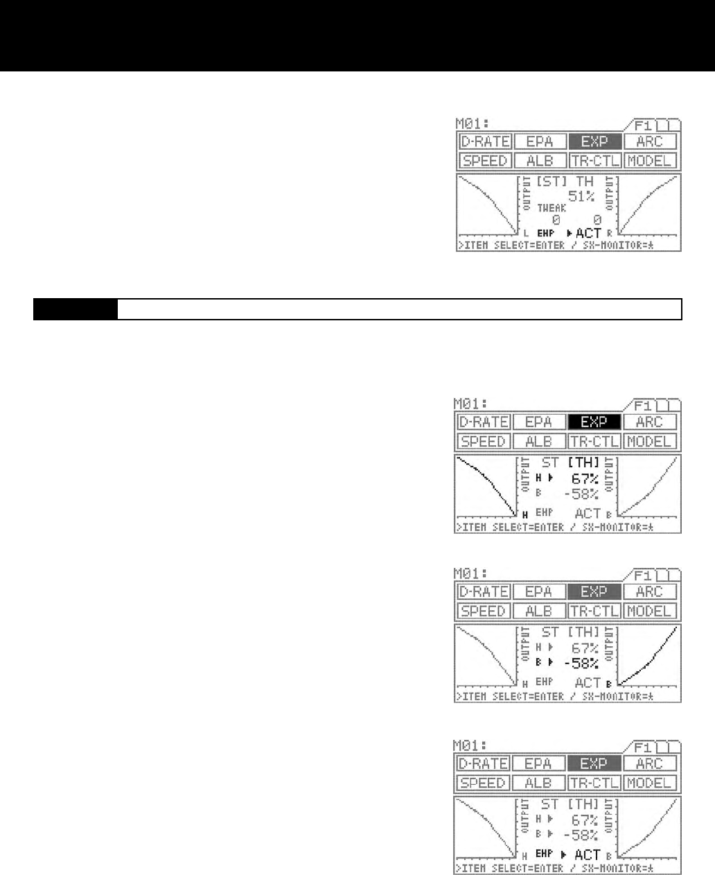
Exponential Page F1 (EXP)
[ST] Steering Exponential
Quick
(1% to 100%) Quick
(1% to 100%)
Mild
(-1% to 100%) Mild
(-1% to 100%)
Normal
0% Normal
0%
Neutral position
Amount of servo operation
Amount of servo operation
Amount of steering wheel operation
on the L side (amount of throttle
trigger operation on the H side)
Amount of steering wheel operation
on the R side (amount of throttle
trigger operation on the B side)
1.
3.
2.
This function varies the amount of servo action with respect to manipulation of the
steering wheel or throttle trigger based from the neutral position. Increasing the
numeric value makes action quicker, while reducing it makes action slower.
Press the function select key and move the cursor to [ST] in EXP.
Set the EXP quantity by pressing the Inc.+ or Dec.- key.
Setting range -100% to 100%
Standard setting 0
TWEAK setting
Use the TWEAK setting when you want to ne-tune the left-right steering bal-
ance.
First, move < or > to below TWEAK with the ENTER key.
To adjust the left side steering, turn the steering wheel to the left and set the
arrow direction to <. To adjust the right side steering, turn the steering wheel to
the right and set the arrow direction to >.
Set the TWEAK quantity by pressing the Inc.+ or Dec.- key.
Setting range -20 to 20
Standard setting 0
Three settings, Mild, Linear and Quick, allow you to set the most effective steering response for your model vehicle. Generally, if
your model vehicle over-steers, reduce the numeric value. If it under-steers, increase the numeric value.
Page 19
[TH Throttle Exponential
4. INH/ACT setting of EXP
In order to activate the EXP function, select ACT; to deactivate, select INH.
Using the ENTER key, move > to the right side of EXP.
Select INH or ACT by pressing the Inc.+ or Dec.- key.
Press the function select key and move the cursor to [TH] in EXP.
Make sure that > appears to the right of H, and then set the EXP amount for
the high side of TH by pressing the Inc.+ or Dec.- key.
Setting range -100% to 100%
Standard setting 0
Move > to the right of B using the ENTER key, and then set the EXP amount
for the brake side of TH by pressing the Inc.+ or Dec.- key.
Setting range -100% to 100%
Standard setting 0
INH/ACT setting in EXP
Select ACT to activate the EXP function. Select INH to deactivate.
Using the ENTER key, move > to the right side of EXP.
Select INH or ACT by pressing the Inc.+ or Dec.- key.
IMPORTANT
About the INH/ACT setting of EXP
The INH/ACT setting of EXP in the menu can also be switched to any desired
key switch by using the key assigning function. By using this function, switch-
ing the EXP “ON” or “OFF” can be selected during operation.
Throttle exponential can be adjusted from Mild, Linear and Quick. Generally, reduce the numeric value on a slippery track or with
models that have powerful response. Increase the numeric value on a high-grip track or with power units that have lower torque.
The high side and brake side can be set independently.
3.
2.
1.
4.
Page 20
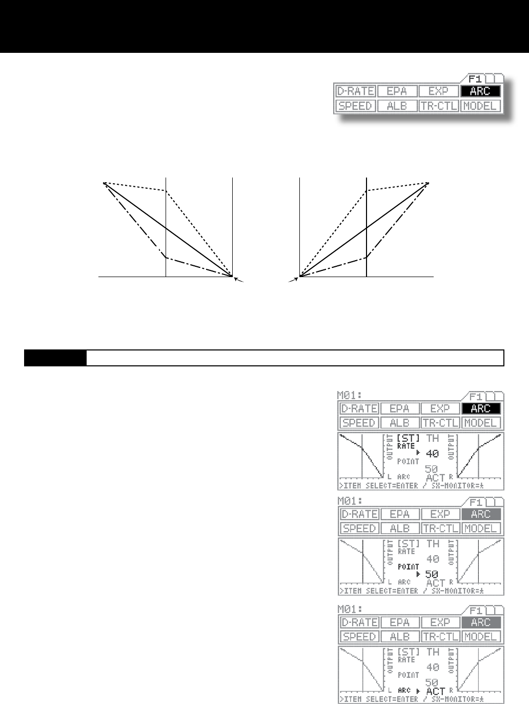
Adjustable Rate Control Page F1 (ARC)
[ST] Steering Adjustable Rate Control
Quick
(1% to 100%) Quick
(1% to 100%)
Mild
(-1% to 100%) Mild
(-1% to 100%)
Normal
0% Normal
0%
Neutral position
Amount of servo operation
Amount of servo operation
Amount of steering operation on the L
side (amount of operation on the
throttle H side)
Amount of steering operation on the
R side (amount of operation on the
throttle B side)
This function varies the amount of servo action with respect to manipulation of
the steering wheel or throttle trigger.
Increasing the rate setting makes action quicker, while reducing it makes ac-
tion milder.
The changeability of the variable point on the ARC enables to adjust delicate
steering and throttle work during the operation.
(-1% to -100%) (-1% to -100%)
Steering response can be variably adjusted from mild through liner or to
quick. In general, if the model vehicle tends to have over-steers, reduce the
numeric value, and if the vehicle tends to have under-steers, increase the
numeric value.
RATE SETTING
Press the function select key and move the cursor to [ST] in ARC.
Be sure that arrow points to the RATE, and then set the RATE for ARC by
pressing the Inc.+ or Dec.- key.
Setting range -100% to 100% (Default setting 0)
POINT setting
Move arrow to POINT with the ENTER key, and then set the POINT value by
pressing the Inc.+ or Dec.- key.
Setting range 5 to 95 (Default setting 50)
INH/ACT setting for ARC
In order to activate the ARC function, select ACT, and to deactivate, select
INH.
Using the ENTER key, move the arrow to the left side of ARC.
Select INH or ACT by pressing the Inc.+ or Dec.- key.
1.
2.
3.
4.
Page 21
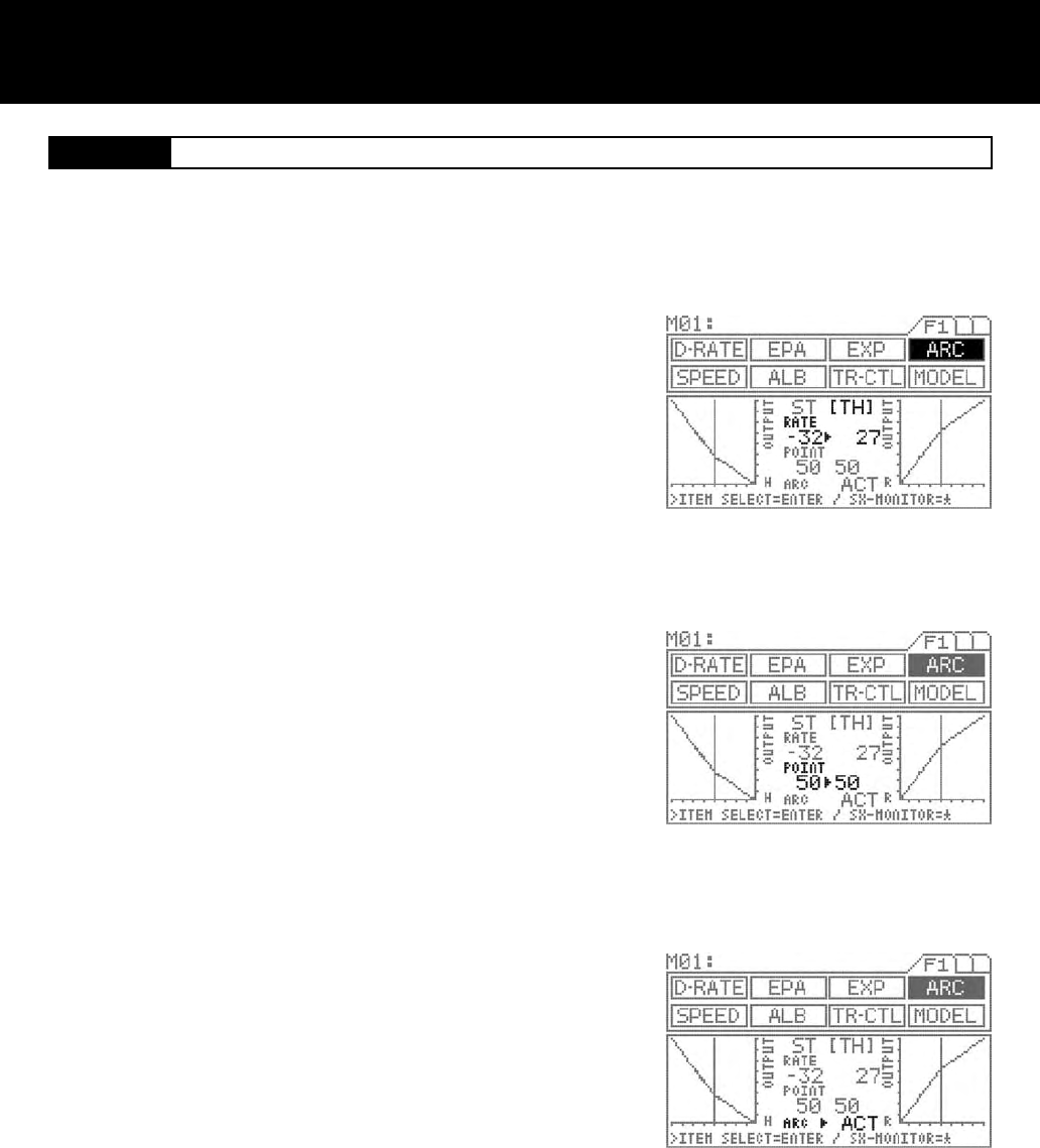
[TH] Throttle Adjustable Rate Control
Press the function select key and move the cursor to [TH] in ARC.
RATE SETTING
Be sure that the arrow appears below RATE.
To adjust the high side throttle setting, pull the throttle trigger all the way to
change the arrow direction to the throttle rate.
To adjust the brake side throttle setting, push the throttle trigger all the way to
the brake side, and watch the arrow direction change to the brake side.
Set the RATE by pressing the Inc.+ or Dec.- key.
Setting range -100 to 100 (Default setting 0)
POINT SETTING
Move the arrow to below POINT with the ENTER key.
To adjust the high side throttle setting, pull the throttle trigger all the way to
the high side, this will change the arrow to the throttle side.
To adjust the brake side throttle setting, push the throttle trigger all the way to
the brake side, and the arrow will change to the brake side.
Set the POINT value by pressing the Inc.+ or Dec.- key.
Setting range 5 to 95 (Default setting 50)
INH/ACT setting for ARC
To activate the ARC function, select ACT, and to deactivate, select INH.
Using the ENTER key, move > to the right side of ARC.
Select INH or ACT by pressing the Inc.+ or Dec.- key.
IMPORTANT
About the INH/ACT setting of ARC
The INH/ACT setting of ARC in the menu can be also switch to any desired key switch by using the key assign function. By
using this function, Activation ,of the ARC “ON” or “OFF” can be selected during the operation.
Throttle characteristic can be variably adjusted from mild through linear or to quick. In general, reduce the numeric value on
slippery track or with models that have powerful response, and increase it on high-grip track or with power units that have
lower torque. The high side and brake side can be set independently.
1.
2.
3.
4.
Page 22
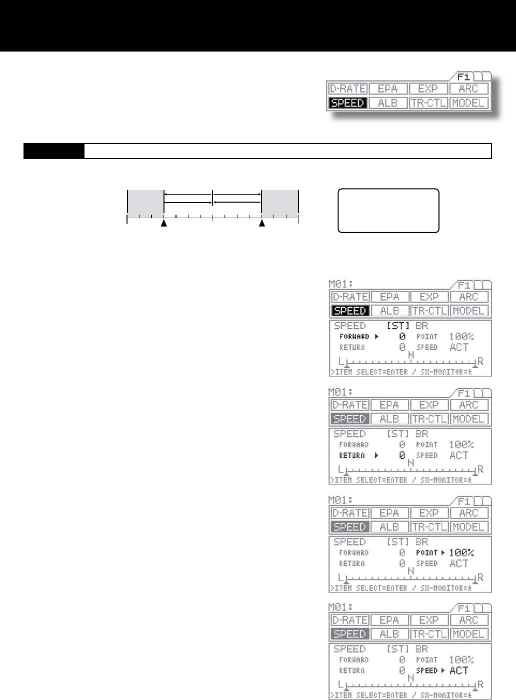
Speed Page F1 (SPEED)
[ST] Steering Servo Speed
L edge R edge
POINT
FORWARD
RETURN RETURN
FORWARD
N
The SPEED setting does not
affect steering when the wheel
is located within the shaded
areas outside the POINT
positions.
Neutral POINT
(5% 100%)(5% 100%)
The SPEED setting does not affect steering when the wheel positioning is
located within the shaded areas outside the POINTS.
Using the function select keys, move the cursor to [ST] in SPEED.
FORWARD SETTING
Make sure that the arrow appears to the right of FORWARD, and then set the
FORWARD value by pressing the Inc.+ or Dec.- key.
Setting range 0 to 100 (Default setting 0)
RETURN SETTING
Move arrow to RETURN with the ENTER key, and then set the RETURN
value by pressing the Inc.+ or Dec.- key.
Setting range 0 to 100 (Default setting 0)
POINT SETTING
Move the arrow to the right of POINT with the ENTER key, and then set the
POINT value by pressing the Inc.+ or Dec.- key.
Setting range 5% to 100% (Default setting 100%)
INH/ACT SPEED
To activate the SPEED function, select ACT, and to deactivate, select INH.
Using the ENTER key, move > to the right of SPEED.
Select INH or ACT by pressing the Inc.+ or Dec.- key.
NOTE
When driving a model vehicle, proper steering is vital, and excessive steering
is to be avoided at all times. The steering speed setting helps to limit exces-
sive steering, which will enable you to achieve smoother cornering.
It is advisable to use both Steering Speed & Exponential functions together
which enable you to achieve the best combination of steering operation.
This function slows down the steering servo speed during steering. Speed can
be set separately for steering movement say from neutral to certain point and
return directions. But note that actual steering operation is slower than in its set
speed of the servo, this function does not affect any.
1.
2.
3.
4.
5.
Page 23
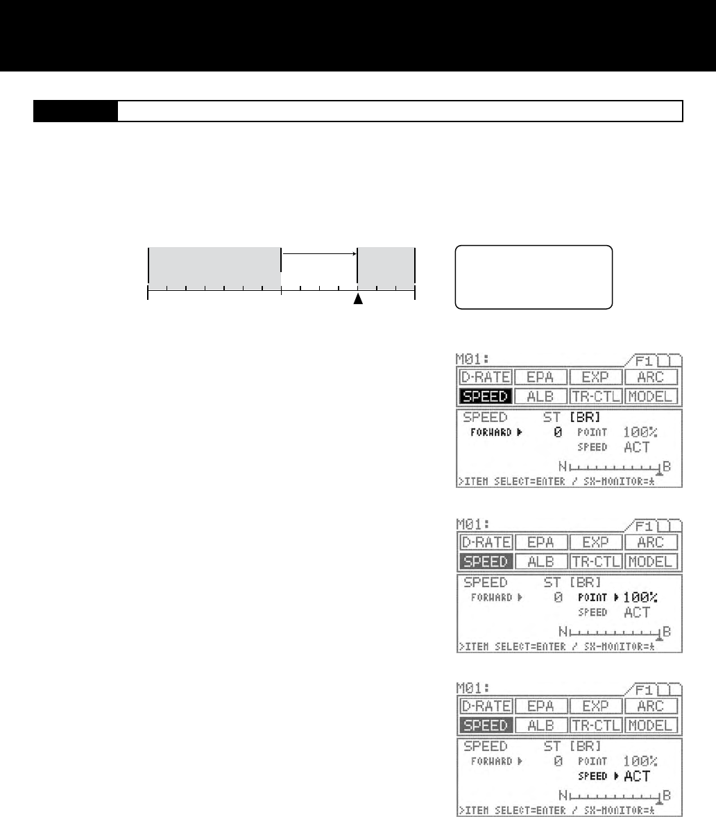
[TH] Throttle Servo Speed
FORWARD
Neutral
N
POINT
(5% 100%)
Hi edge B edge
The SPEED setting does not
affect throttle operation when
the throttle trigger is located
within the shaded areas outside
the POINT positions.
Using the function select keys, move the cursor to [BR] in SPEED.
FORWARD SETTING
Make sure the arrow appears to the right of FORWARD, and then set the
FORWARD value by pressing the Inc.+ or Dec.- key.
Setting range 0 to 100 (Default setting 0)
POINT SETTING
Move the arrow to the right of POINT with the ENTER key, and then set the
POINT value by pressing the Inc.+ or Dec.- key.
Setting range 5% to 100% (Default setting 100%)
INH/ACT SPEED
To activate the SPEED function, select ACT, and to deactivate, select INH.
Using the ENTER key, move the arrow to the right of SPEED.
Select INH or ACT by pressing the Inc.+ or Dec.- key.
This function slows down the throttle servo during throttle operation. This setting affects only the FORWARD side of the brake.
The SPEED setting does not affect throttle operation when the throttle trigger positioning is located within the shaded areas outside
the POINT. (Only affect from the neutral to the point set at.)
1.
2.
3.
4.
NOTE
It is advisable to use both Throttle’s Speed & Exponential functions together which enable to achieve best combination of the steer-
ing operation for the model vehicle.
IMPORTANT
About the INH/ACT setting for SPEED
The INH/ACT setting of SPEED in the menu can be also switch to any desired key switch by using the key assign function. By using
this function, switching the SPEED “ON” or “OFF” can be selected during the operation.
Page 24
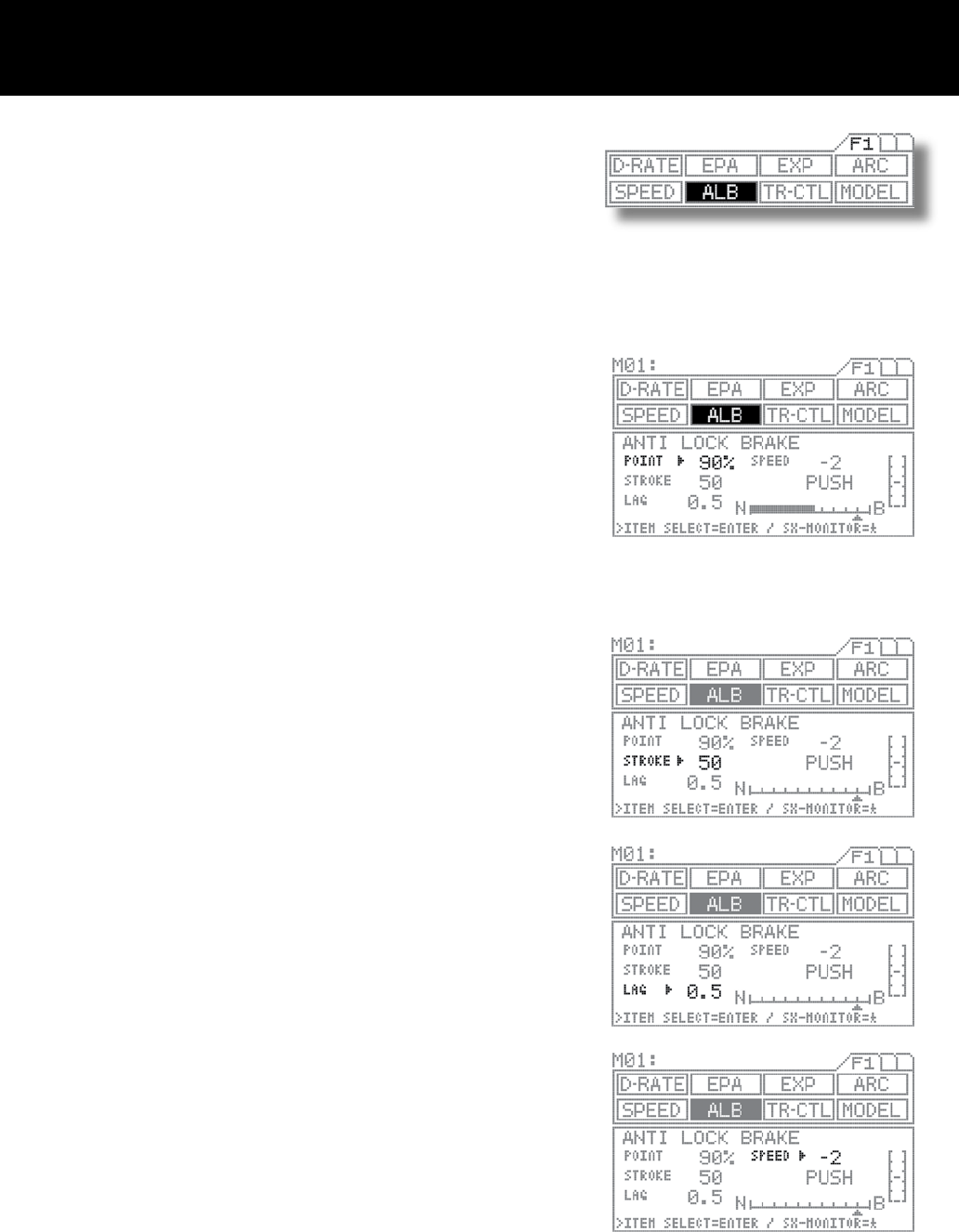
Anti-Lock Braking (For Gas powered model only) Page F1 (ALB)
Using the function select keys, move the cursor to ALB.
POINT SETTING
Be sure that arrow appears to the right of POINT, and then set the POINT
value by pressing the Inc.+ or Dec.- key.
POINT: The position where ALB activates.
Setting range 0% to 100% (Default setting 90%)
STROKE SETTING
Move the arrow to the right of STROKE with the ENTER key, and then set the
STROKE value by pressing the Inc.+ or Dec.- key.
STROKE: The width of repeated operation.
Setting range 0 to 100 (Default setting 50)
LAG SETTING
Using the ENTER key, move the arrow to the right of LAG.
Set the POINT value by pressing the Inc.+ or Dec.- key.
LAG: The time lag before ALB activates.
Setting range 0.0 to 2.0 (Default setting 0.5)
SPEED SETTING
Move the arrow to the right of SPEED with the ENTER key, and then set the
SPEED value by pressing the Inc.+ or Dec.- key.
SPEED: The speed of repeated operation.
Setting range -1 to -30 (Default setting -2)
NOTE
Set the hardest brake can be obtain from your model vehicle but carefully set
the anti-lock braking at the point where right before the tires get fully locked
but not to slip and lose the traction at the track.
Anti-lock braking is effective only as long as the ALB switch is depressed.
Anti-lock braking makes it possible to achieve stable braking even on a slip-
pery track. With stable braking, the model vehicle may be able to trace an
exact line as desired for corners.
This function also enables you to set the different Braking characteristics
depending on the model vehicle for on road racing or the off road buggy .
1.
2.
3.
4.
4.
Page 25
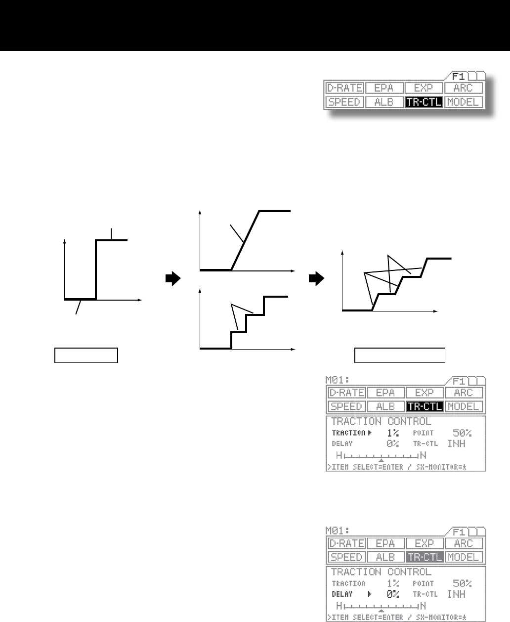
Traction Control Page F1 (TR-CTL)
N
H
Full high
Trigger operation
Neutral
Trigger operation
Traction control
Traction control
Delay control
Delay control
* In this example, the POINT value is 100%.
Trigger operation position
OperationOperation
Operation
Time
Time
Time
Time
Using the function select keys, move the cursor to TR-CTL..
TRACTION SETTING
Be sure the arrow appears to the right of TRACTION, and then set the TRAC-
TION value by pressing the Inc.+ or Dec.- key.
Setting range 1% to 100% (Default setting 1%) (off)
Full throttle position
POINT position (Bar graph (allows verication of output)
DELAY SETTING
Move the arrow to the right of DELAY with the ENTER key, and then set the
DELAY value by pressing the Inc.+ or Dec.- key.
Setting range 0% to 100% (Default setting 0%)
Traction control helps assure faster, smoother starts even when the trigger is
applied abruptly by not having wheel spins.
Even the model vehicle is on the forward motion, it contributes the stability
during acceleration, providing smoother running.
Ideal smoothness can be further rened by adjusting for intermittent locking in addition to normal servo speed delay adjust-
ment. By making point settings and switch assignments (with the key assign function), traction control can be applied when-
ever necessary, at just the places if necessary.
* This function operates only when the throttle is moved from Neutral to the Hi direction.
1.
2.
3.
Page 26
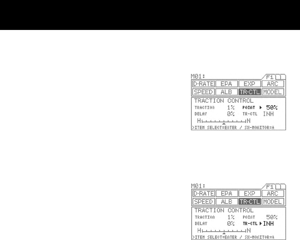
POINT SETTING
Move the arrow to the right of POINT with the ENTER key, and then set the
POINT value by pressing the Inc.+ or Dec.- key.
Setting range 5% to 100% (Default setting 50%)
Traction control applies only in the range from neutral to the set point.
NOTE
The point referred to here is the operational output point, not the trigger
operation point..
INH/ACT setting for TR-CTL
To activate the traction control function, select ACT, and to deactivate, select
INH.
Using the ENTER key, move > to the right of TR-CTL.
Select INH or ACT by pressing the Inc.+ or Dec.- key.
IMPORTANT
The INH/ACT setting of traction control in the menu can be also switched
to any desired key switch by using the key assign function. By using this
function, switching the TR-CTL “ON” or “OFF” can be selected during the
operation.
4.
4.
Page 27
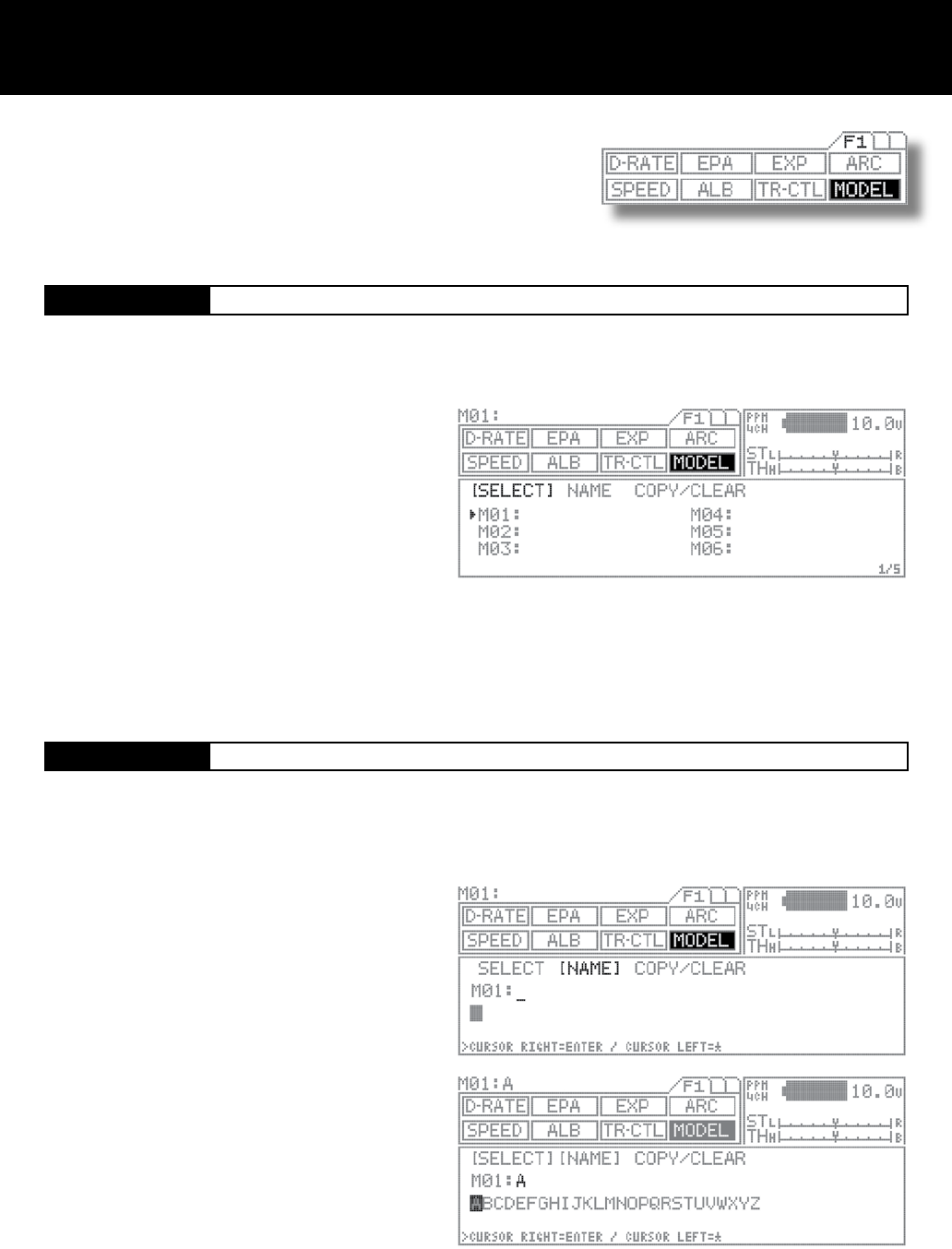
Model Page F1 (MODEL)
[SELECT] Model Select
[NAME] Model Name
Using the function select keys, move the cursor to
[NAME] in MODEL.
Using the asterisk key or the ENTER key, move the cur-
sor (“_”) to the point when you want to enter text.
Select a character by pressing the Inc.+ or Dec.- key.
Repeat steps 2) and 3) for each subsequent character.
Setting range A – Z, a – z, 0 – 9, symbols, space
NOTE
Group of characters can be ip through in sequence A-
>a->0->!->space-> by simultaneously pressing the Inc.+
and Dec.- keys.
When entering a character in a position occupied by a
space, group can be selected from the preceding char-
acter by rst pressing the Dec./- key. This is useful when
entering several characters from the same group.
This menu enables you to make settings related to model select (SELECT),
model name (NAME), and model copy/model clear (COPY/CLEAR) func-
tions.
Data for up to 30 models, M01 to M30, can be stored in the M11’s high
capacity, built-in EEPROM memory.
Using the function select keys, move the cursor to
[NAME] in MODEL.
Select the model to be recalled by pressing the Inc.+ or
Dec.- key.
Setting range M01 to M30
Data can be easily stored for any models M01 to M30.
Since the previous model memorys are stored automatically, there is no risk for accidental erasing.
1.
2.
NOTE
The model changes immediately upon selection.
Pages can be ip through in sequence such as M01->M07->M13->M19->M25->M1…by simultaneously pressing the Inc.+ and
Dec.- keys.
! CAUTION
Do not attempt to change the model when the model vehicle’s receiver is being turned on under the actual operational condition
resulting that Model vehicle may go runaway or the servo may be damaged being set with other servo setting.
Model names can be registered as consisting of up to 12 letters, numerals, or symbols.
1.
2.
3.
4.
Page 28
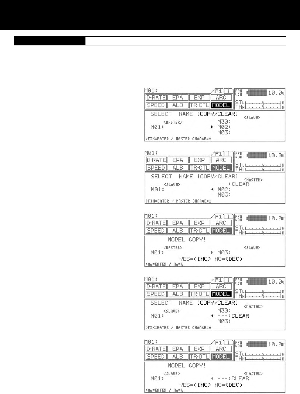
[COPY/CLEAR] Model Copy / Model Clear
COPY MODEL DATA
Using the function select keys, move the cursor to
[COPY/CLEAR] in MODEL.
To copy data from the current selected (Master) model
to another model (Slave), use the INC/+ or DEC/- keys
to change the model numbers up or down to the model
number you would like to copy the current model (Mas-
ter) to.
After you have selected the model number you wish to
copy the current model (Master) to, press the ENTER
key. The screen will now change and ask you:
YES=<INC> and NO=<DEC>
Press the INC/+ key to copy the current (Master) model
to the new model (Slave) you have selected. Press the
DEC/- key to return to the previous screen.
To copy data from another model to the one your cur-
rently using, use the star key to change the current
model (Master) to (Slave). In turn the model you would
like to copy from will now show (Master). The (Master)
will always overwrite the (Slave).
Select the model (Master) you want to copy from using
the Inc.+ or Dec.- keys and then press the ENTER key.
A conrmation screen appears, allowing to conrm that
choice is correct. To proceed with copying, press Inc.+,
or to cancel press Dec.- key. During copying, the mes-
sage EXECUTING! appears until copying is completed.
CLEARING MODEL DATA
Using the function select keys, move the cursor to
[COPY/CLEAR] in MODEL.
Using the star key, change the current model (Master) to
(Slave).
Press both INC/+ or DEC/- keys simultaneously to select
the (- - -:CLEAR) model.
Now press the ENTER key to select. The screen will
change and ask, YES=<INC> or NO=<DEC>. Select yes
to clear the current model or no to return to the previous
screen. This operation clears all data for models M01 to
M30.
NOTE:
CLEAR can be selected by simultaneously pressing
Inc/+ and Dec/-.
While clearing is in progress, the message EXECUTING!
appears until operation is completed.
This function enables you to copy data from the currently selected model to another, or to copy another model’s data into the model
currently selected. Data can be cleared (initialize) on the current model that being selected.
1.
2.
3.
4.
5.
6.
7.
8.
9.
Page 29
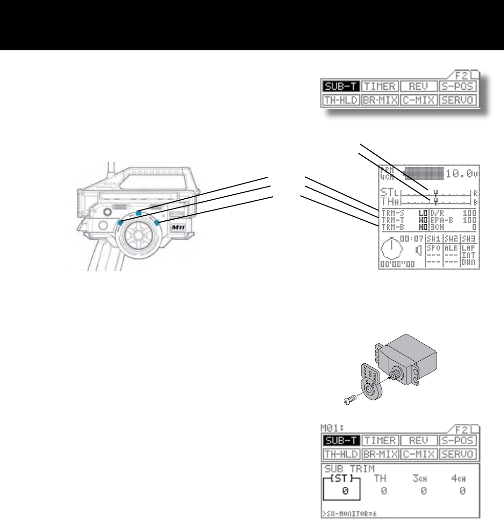
Sub-Trim Page F2 (SUB-T)
Corrects trim neutral for steering and throttle, making it possible to use the main
trim from the center position. When adjusting linkages, this sub-trim allows to x
the position in accurate center position.
* This can also be used for brake sub-trim when using 4 channels. In this case,
channels 3 and 4 can be set independently.
Before adjusting linkage, be sure to set the main
trimmers to center position (0).
Attach the servo arm (servo saver arm) to the servo
unit in the position that is closest to neutral.
Using the function select keys, move the cursor to
[ST] in SUB-T.
Adjust the sub-trim to center the servo arm the the
servo.
Setting range 100L to 100R (Default setting 0)
Adjust the other sub-trim settings in the same man-
ner.
! CAUTION
Be sure that the servo is as nearly centered as possible before making this adjustment. If the sub-trim and main trim set-
tings are both offset to one side, an operational dead spot (a spot where the servo does not operate) may result.
Steering
Throttle
Brake
Steering
Throttle
(Factory Default Trim Locations)
(Set on 4 Channel)
1.
2.
3.
4.
5.
Page 30
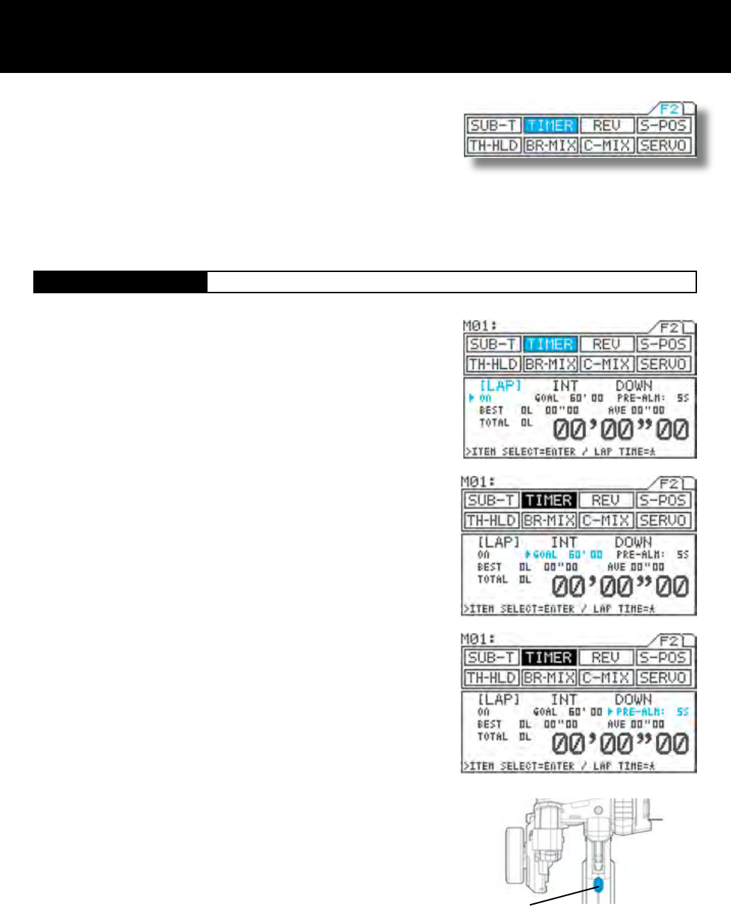
Timer Page F2 (TIMER)
SW3
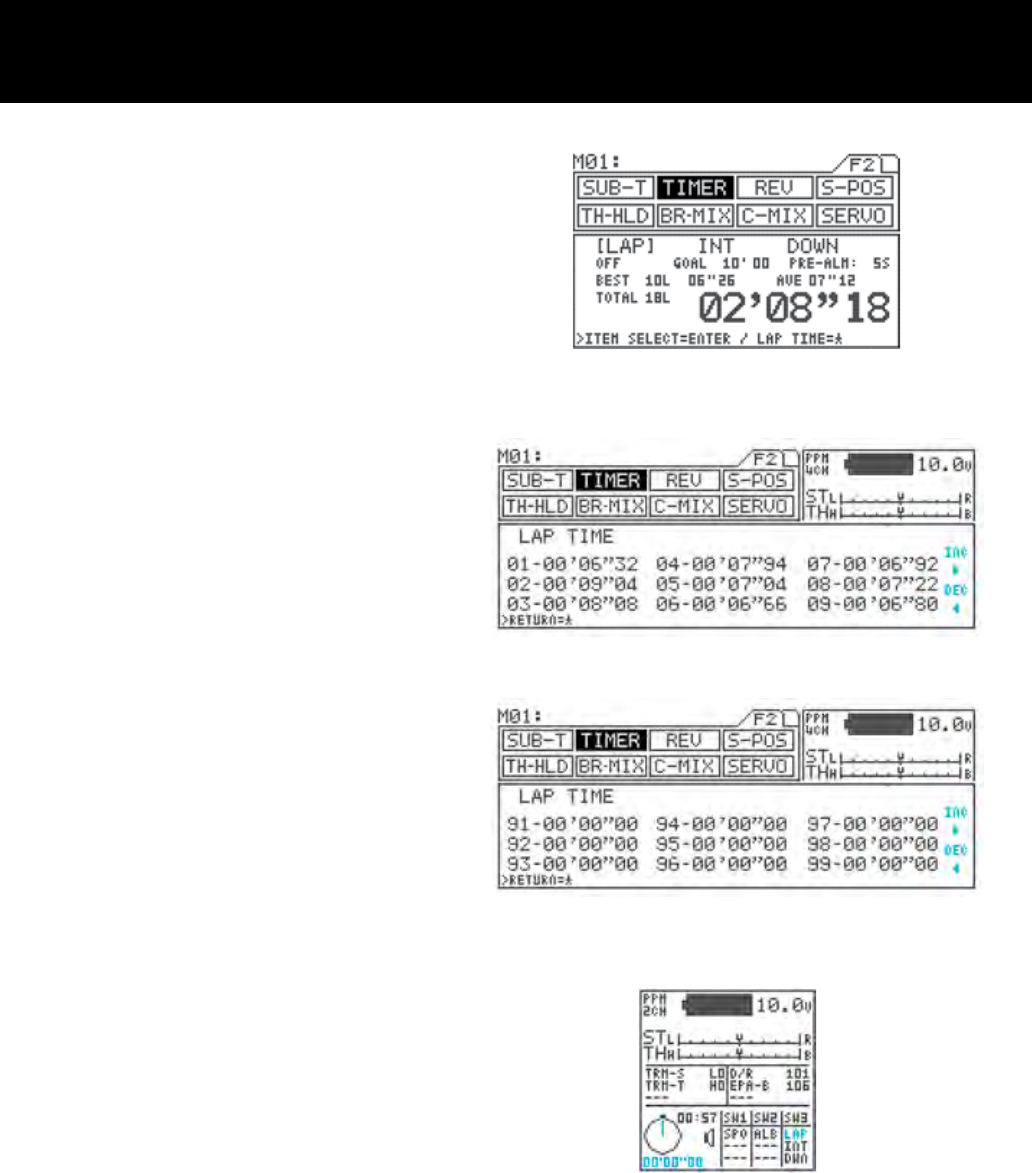
[LAP] Lap Timer
Allows you to measure and record times for up to 99 laps (all models).
Features a pre-alarm (PRE-ALM) that lets you set a pre-goal alarm time.
Provides real-time display of the best lap (BEST), average lap (AVE), and
total (TOTAL) lap times.
Using the function select keys, move the cursor to [TH] in TIMER.
Turning the lap timer (ON/OFF)
Be sure that arrow appears below LAP, and then press Inc.+ or Dec.- to set
the timer ON or OFF.
Setting the goal time (GOAL)
Press the ENTER key to move the arrow to GOAL, and then set the goal time
by pressing the Inc.+ or Dec.- key.
Setting range 00’10 to 60’00 In 00’10 increments (Default setting 60’00)
Setting the pre-alarm (PRE-ALM)
Press the ENTER key to move the arrow to PRE-ALM, and then set the pre-
alarm by pressing the Inc.+ or Dec.- key.
The pre-alarm is an alarm that sounds a few seconds before the goal time.
Setting range OFF, 1s to 20s (Defailt setting 5s)
With the standard conguration, the lap timer switch is set to SW3. Pressing
SW3 starts measurement.
Lap time is measured each time you press SW3. Once you press the switch, it
is deactivated for 3 seconds.
IMPORTANT
About the timer switch
The timer switch can be freely assigned to another switch using the key as-
sign function. Set the switch to the position that is most suitable.
Three types of timers are provided for measuring lap, interval, and down (or
up) times, and these three timers can be used simultaneously.
A high degree of freedom and convenience is provided by the ability to use
the key assign switch to perform simultaneous or independent operation.
Separate tones can be assigned to each of the timers, making it easy to
distinguish between them during simultaneous operation.
The audible signal provided by the tone is complemented by a vibrator, which can be set to operate either in concert with
the tone, or simultaneously.
The operational status of the timers can also be checked from other menus (in the constant display area).
1.
2.
3.
4.
5.
Page 31
ENDING MEASUREMENT
End measurement can be set in three different ways.
By pressing the switch after the goal time is reached.
By pressing the switch after the goal time is reached.
By pressing and holding the switch for 3 seconds.
VERIFYING MEASUREMENT RESULTS
Measurement results can be checked using the
star key in the TIMER [LAP] menu while the timer is
stopped.
The display shows times for 9 laps at a time, Pages
can be ip by using the Inc.+ or Dec.- key.
Pressing Inc.+ and Dec.- simultaneously returns dis-
play to the rst 9 laps.
CONSTANT DISPLAY AREA
The timer status appears in the constant display area,
and can also be checked from other menus.
The timers appear in the timer display area in the order
FUNC1>FUNC2>FUNC3, as set with the key assign
switch. In the example at right, LAP appears as as-
signed to FUNC1.
! CAUTION
When measurement is started, the previous LAP
measurement is cleared. There is no function that is
provided for clearing the lap time.
When measurement ends, the timer’s ON/OFF status
changes to OFF. To re-start the timer, turn in ON as
described in step 2).
6.
7.
8.
Page 32
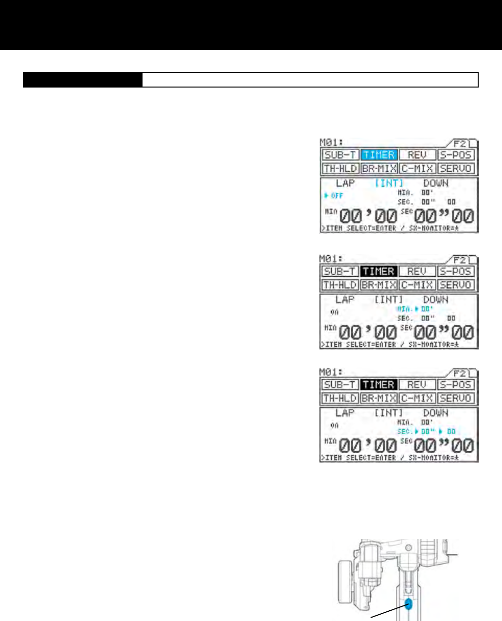
[INT] Interval Timer
SW3
Using the function select keys, move the cursor to [INT] in TIMER.
Turning the interval timer ON/OFF
Make sure that the arrow appears below LAP, and then press Inc.+ or Dec.-
to set the timer ON or OFF.
Setting the interval minute timer (MIN)
Press the ENTER key to move the arrow to the right of MIN, and then set
the timer by pressing the Inc.+ or Dec.- key.
The interval minute timer will not function when it is set as 00’.
Setting range 00’ to 99’ 01’ increments (1-minute increments)
(Default setting 00’)
Setting the interval second timer (SEC)
Press the ENTER key to move the arrow to the right of SEC, and then set
the timer by pressing the Inc.+ or Dec.- key.
Setting range 00” to 59” 01” increments (1-second increments)
(Default setting 00’)
1/10-Seconds Setting
Press the ENTER key to move the arrow to the left of 00”, and then set the
timer by pressing the Inc.+ or Dec.- key.
Setting range 00 to 90 Increments of 10 (1/10-second increments)
(Default setting 00)
The interval second timer will not function when it is set as 00”00.
With the standard conguration, the lap timer switch is set to SW3. By
pressing the SW3 starts measurement.
Each time you press SW3, the interval timer is reset and measurement re-
starts from 0 minutes, 0 seconds.
The interval timer noties when a set interval elapses while you are driving, giving you an idea how close you are to
your target time. Interval timers are provided separately for minutes and seconds, and both can be used simultaneously.
Timer tone can be also set separately for each two timers.
1.
2.
3.
4.
4.
5.
Page 33
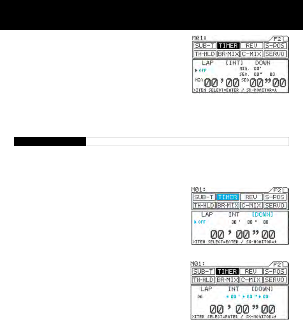
[DOWN] Down Timer
ENDING MEASUREMENT
End of measurement can be deactivated in two different ways.
From the menu, by simultaneously pressing the Inc.+ and Dec.- key.
By pressing and holding the switch for 3 seconds.
6.
IMPORTANT
When measurement ends, the timer’s ON/OFF status changes to OFF. To re-start the timer, turn in ON as described in step 2).
About the timer switch
The timer switch can be freely assigned to another switch using the key assign function. Set the switch to the position that is most
suitable.
Using the function select keys, move the cursor to [DOWN] in TIMER.
Turning the down timer ON/OFF
Be sure that arrow appears below LAP, and then press Inc.+ or Dec.- to set
the timer ON.
Setting the down timer (minute)
Press the ENTER key to move the arrow to (minute), and then set the timer
by pressing the Inc.+ or Dec.- key.
Setting range 00’ to 99’ 01” increments (1-second increments)
(Default setting 00”)
Setting the down timer (second)
Press the ENTER key to move the arrow to (second), and then set the timer
by pressing the Inc.+ or Dec.- key.
Setting range 00” to 59” 01” increments (1-second increments)
(Default setting 00”)
Setting the down timer (1/10-second)
Press the ENTER key to move the arrow to (1/10-second), and then set the
timer by pressing the Inc.+ or Dec.- key.
Setting range 00 to 90 Increments of 10 (1/10-second increments)
(Default setting 00”)
The timer will not function when it is set at 00” 00.
This timer can notify the idea of model vehicle’s battery or fuel consumption (running time).
The timer accepts settings of up to 99’ 59” 90 in 1/10-second increments.
Once the down timer has run out, the up timer starts. This allows you to check the time elapsed since the timer ran out.
(This timer has an alarm that sounds every minute.)
1.
2.
3.
4.
5.
IMPORTANT
When measurement ends, the timer’s ON/OFF status changes to OFF. To re-start the timer, turn in ON as described in step 2).
About the timer switch
The timer switch can be freely assigned to another switch using the key assign function. Set the switch to the position that is
most suitable for you.
Page 34
SW3
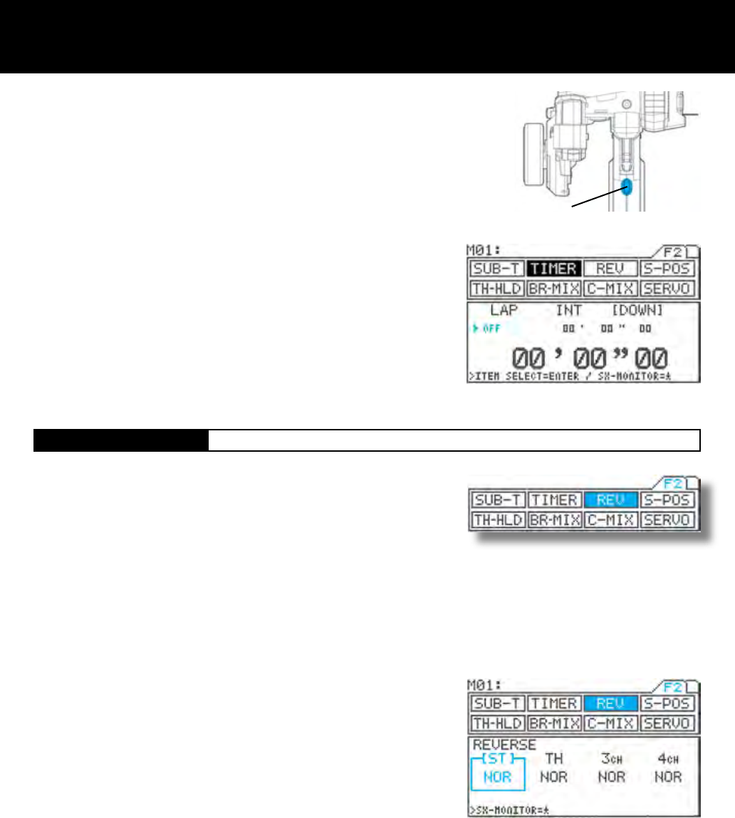
[REV] Servo Reversing
Timer / Servo Reversing Page F2 (REV)
With the standard conguration, the down timer switch is set to SW3. Pressing
SW3 starts measurement.
Each time you press SW3, the interval timer is restored to its preset value, and
the countdown re-starts from that setting.
ENDING MEASUREMENT
End of measurement can be deactivated in two different ways.
From the menu, by simultaneously pressing the Inc.+ and Dec.- key.
By pressing and holding the switch for 3 seconds.
IMPORTANT
*When measurement ends, the timer’s ON/OFF status changes to OFF. To
re-start the timer, turn in ON as described in step 2).
*About the timer switch
The timer switch can be freely assigned to another switch using the key assign
function. Set the switch to the position that is most suitable for you.
6.
This function is to switch the direction of servo operation, and is used in
situations when controls such as the steering wheel or throttle operate in the
opposite direction .
Servo reversed can be individually adjusted for each of the 4 channels.
Using the function select keys, move the cursor to [ST] in REV.
Set the direction of servo operation by pressing the Inc.+ or Dec.- key.
Setting range NOR/REV
Standard setting NOR
Make settings for the other channels in the same manner.
1.
2.
3.
Page 35
N
H B
100%~0% 0%~100%
{
{
S-POS Range BRAKE-POINT Range
S-POS BRAKE-POINT
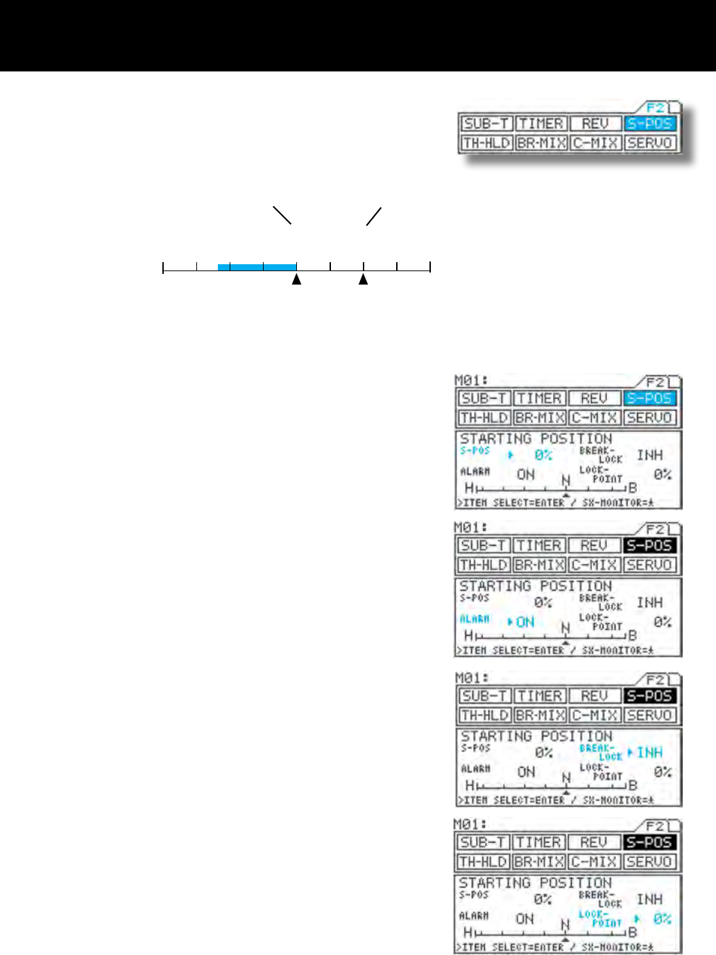
Start Position Page F2 (S-POS)
Using the function select keys, move the cursor to S-POS.
S-POS level setting
Be sure that arrow appears to the right of S-POS, and then set the S-POS
value by pressing the Inc.+ or Dec.- key.
Turning the alarm ON/OFF
Press the ENTER key to move the arrow to the ALARM, and then set the
alarm by pressing the Inc.+ or Dec.- key.
Ordinarily, leave the alarm ON.
BRAKE-LOCK setting
Press the ENTER key to move the arrow to BREAK-LOCK, and then choose
the setting by pressing the Inc.+ or Dec.- key.
The BRAKE-LOCK setting is effective when channel 4 is selected, and the
S-POS switch is ON or ACT selected, the brake channel is xed at the LOCK-
POINT value regardless of trigger operation.
LOCK-POINT setting
Press the ENTER key to move the arrow key to LOCK-POINT, and then
choose the setting by pressing the Inc.+ or Dec.- key.
Setting range 0% to 100%
(Defualt setting 0%)
IMPORTANT
About the S-POS switch
The S-POS switch can be freely assigned to another switch using the key as-
sign function. Set the switch to the position that is most suitable for you.
With engine-powered models, by revving the idling a little, it makes easier
to start up the engine. When using a channel other than 2CH for braking, a
certain degree of braking can be applied independently of trigger operation,
making it possible to obtain safer engine starts. (This works when the S-POS
switch is ON. Trigger operation starts at the point determined by the S-POS
setting.
TIP When the S-POS switch is OFF, the S-POS position is at N (neutral).
1.
2.
3.
3.
4.
Page 36
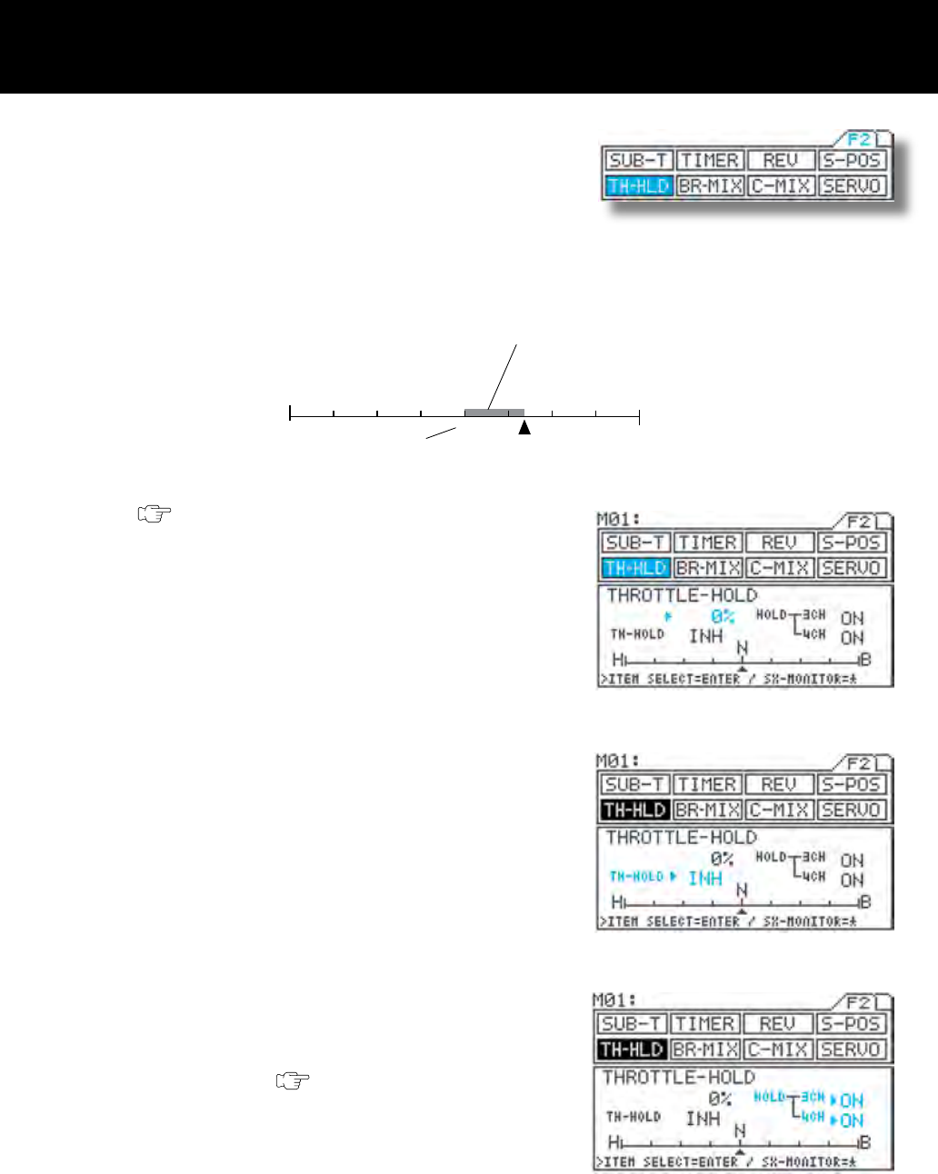
Throttle Hold Page F2 (TH-HLD)
* This function enabled to stop the engine by pressing the button switch for
the models such as RC boats. (As known as “ENGINE CUT”)
* This can be used as an emergency brake while driving a model vehicle
by pressing the switch, trigger is disabled as long as the switch is de-
pressed.
* With engine-powered models, “THROTTLE HOLD” function enabled to set
the throttle slightly open to hold the steady engine idling. This will prevent
the engine from stopping during refueling on the pit stop.
1) First, assign TH-HLD to the switch wherever switch
location desired by using key assign function.
( page 44)
* The throttle hold function works only when the
TH-HLD switch is depressed.
2) Using the function select keys, move the cursor to
TH-HOLD.
3) Make sure that u appears to the left of the percent-
age value, and then set the TH-HOLD percentage
by pressing the Inc.+ or Dec.- key.
* Setting range -160% to 140%
* Original setting 0
* When TH-HLD is ON, the servo is locked to the
preset position, regardless of the current trigger
position.
4) Setting INH/ACT for TH-HOLD
Move u to the right of TH-HOLD with the ENTER
key, and then select INH or ACT by pressing the
Inc.+ or Dec.- key.
* Ordinarily, select INH to use this function.
When ACT is selected, pressing the switch cancels
throttle hold.
5) Setting HOLD-3CH
Move u to the right of HOLD-3H with the ENTER
key, and then select the setting by pressing the Inc.+
or Dec.- key.
* This setting is effective only when 3CH-BRAKE
is active. (BR-MIX page 34)
6) Setting HOLD-4CH
Move u to the right of HOLD-4CH with the ENTER
key, and then select the setting by pressing the Inc.+
or Dec.- key.
* This setting is effective only when 4CH is se-
lected.
H B
N
Neutral
High side Brake side
TH-HOLD position
Bar graph
Indicates the throttle servo travel.
140% 0% -16%
Page 37
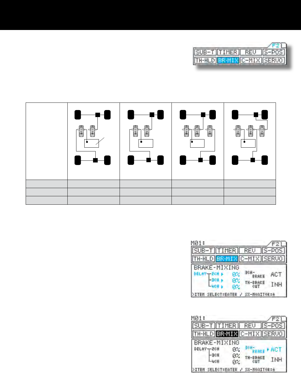
Brake Mix Page F2 (BR-MIX)
* This function makes it possible to adjust servo mixing with models which re-
quires two servos for braking, such as 1/5-scale engine-powered models.
* REV, EPA, SUB-T, and delay can be set independently for each channel,
providing exibility for adjustment of different model types.
* Brake trim is provided separately from throttle trim.
* If intended not to use the brake on 2nd channel, (2CH), brake side can be
disabled.
(TH-BRAKE CUT function)
* Settings for
various model
types
1ch:
Steering
rear brake
front brake
engine
2ch 3ch
1ch
: Steering
3ch
: AUX
2ch 4ch
1ch
: Steering
2ch 3ch 4ch
1ch
: Steering
2ch 3ch 4ch
Receiver type 3channel 4channel 4channel 4channel
3CH-BRAKE ACT INH ACT ACT
TH-BRAKE CUT INH INH ACT ACT
* A variety of other model types are also supported.
1) Using the function select keys, move the cursor to
BR-MIX.
2) Setting DELAY
<2CH>
Be sure that u appears to the right of DELAY-2CH,
and then set the DELAY value by pressing the Inc.+
or Dec.- key.
<3CH>
Move u to the right of DELAY-3CH with the ENTER
key, and then set the DELAY value by pressing the
Inc.+ or Dec.- key.
<4CH>
Move u to the right of DELAY-4CH with the ENTER
key, and then set the DELAY value by pressing the
Inc.+ or Dec.- key.
3) Setting INH/ACT for 3CH-BRAKE
Move u to the right of 3CH-BRAKE with the ENTER
key, and then select INH or ACT by pressing the
Inc.+ or Dec.- key.
* This setting determines whether channel 3 is used
for brakes or as an AUX channel.
It is a brake channel when ACT is selected.
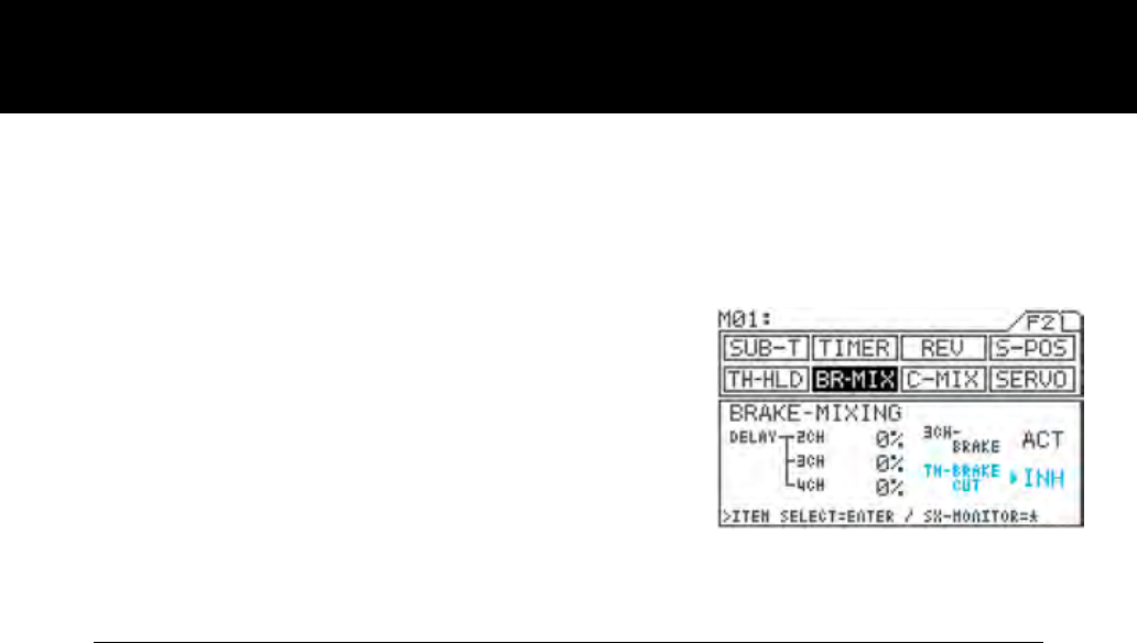
Page 38
4) Setting INH/ACT setting for TH-BRAKE CUT.
Move u to the right of TH-BRAKE CUT with the
ENTER key, and then select INH or ACT by pressing
the Inc.+ or Dec.- key.
* If intended not to use brake side of the throttle
channel (2CH), servo operation can be disabled
on the brake side by selecting ACT. This reduces
the time lag of servo operation compared to that
when using the throttle channel (2CH) for brak-
ing.
IMPORTANT
- Do not use the TH-BRK CUT function when 2CH is selected.
- Be sure to set the menu as 4channel! If 2CH is selected, function can be used partially.
- Select 4CH (through the SET-UP menu) and Be sure to set the 3CH-BRAKE rst, before the adjusting linkage.
(Before adjusting REV, EPA, and SUB-T.)
Page 39
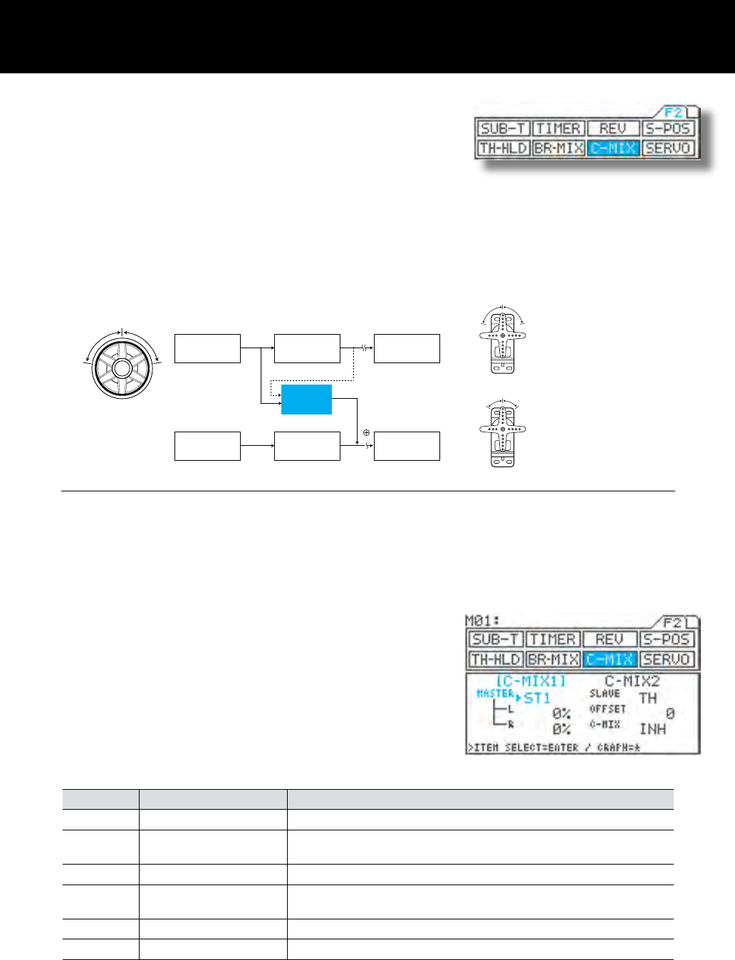
C-Mix Page F2 (C-MIX)
* This function allows you to mix channels and to apply mixing to the channels
themselves.
* On the master channel, you can select from between direct data, and data
that includes calculations and trim.
* There are two groups of C-MIX settings, and you can use the two simultane-
ously.
NOTE
* With normal steering, control has a ow that starts with steering wheel manipulation, proceeding through calcula-
tion, to servo output (CH1). With the C-MIX function, if the steering is moved by a certain amount (for example,
100 as shown in the gure above), 10% of that amount is applied to the CH2 servo, so that the CH2 servo moves
by 10 as the steering servo moves by 100. The channel on which steering operation takes place is referred to as
the “MASTER” , and the channel that operates at 10% of the master level is referred to as the “SLAVE”.
1) Using the function select keys, move the cursor to
C-MIX1.
2) Make sure that u appears to the right of MASTER,
and then set the master channel by pressing the
Inc.+ or Dec.- key.
Setting Name Master output data
* ST1 Steering Master 1 Steering operation only
* ST2 Steering Master 2 Steering plus calculated amount of operation for SPEED, EXP, ARC,
D/R, EPA, and trim (including sub-trim)
* TH1 Throttle Master 1 Throttle operation only
* TH2 Throttle Master 2 Throttle plus calculated amount of operation for SPEED, TR-CNT,
BR-MIX, EXP, ARC, S-POS, EPA, and trim (including sub-trim)
* AUX1 AUX Master 1 AUX operation only
* AUX2 AUX Master 2 AUX plus calculated amount of operation for EPA
* Using the offset function, you can move the origin for master mixing.
* You can easily turn the C-MIX function ON or OFF while driving (with the key assign switch).
* Graphic indication makes it easy to understand setting of mixing.
Example) MASTER:ST1, L:10%, R:10%, SLAVE:TH, OFFSET:0
100100
Steering wheel
Steering
operation
Master 1 Calculation Servo output CH1
CH2
100100
1010
Steering servo
Throttle servo
The uncompensated steering
data is output as Master 1,
and the data after calculation
is output Master 2.
Master 2
Throttle
operation Calculation Servo output
C-MIX 100*0.1=10
(10%)
Page 40
H
L R
B
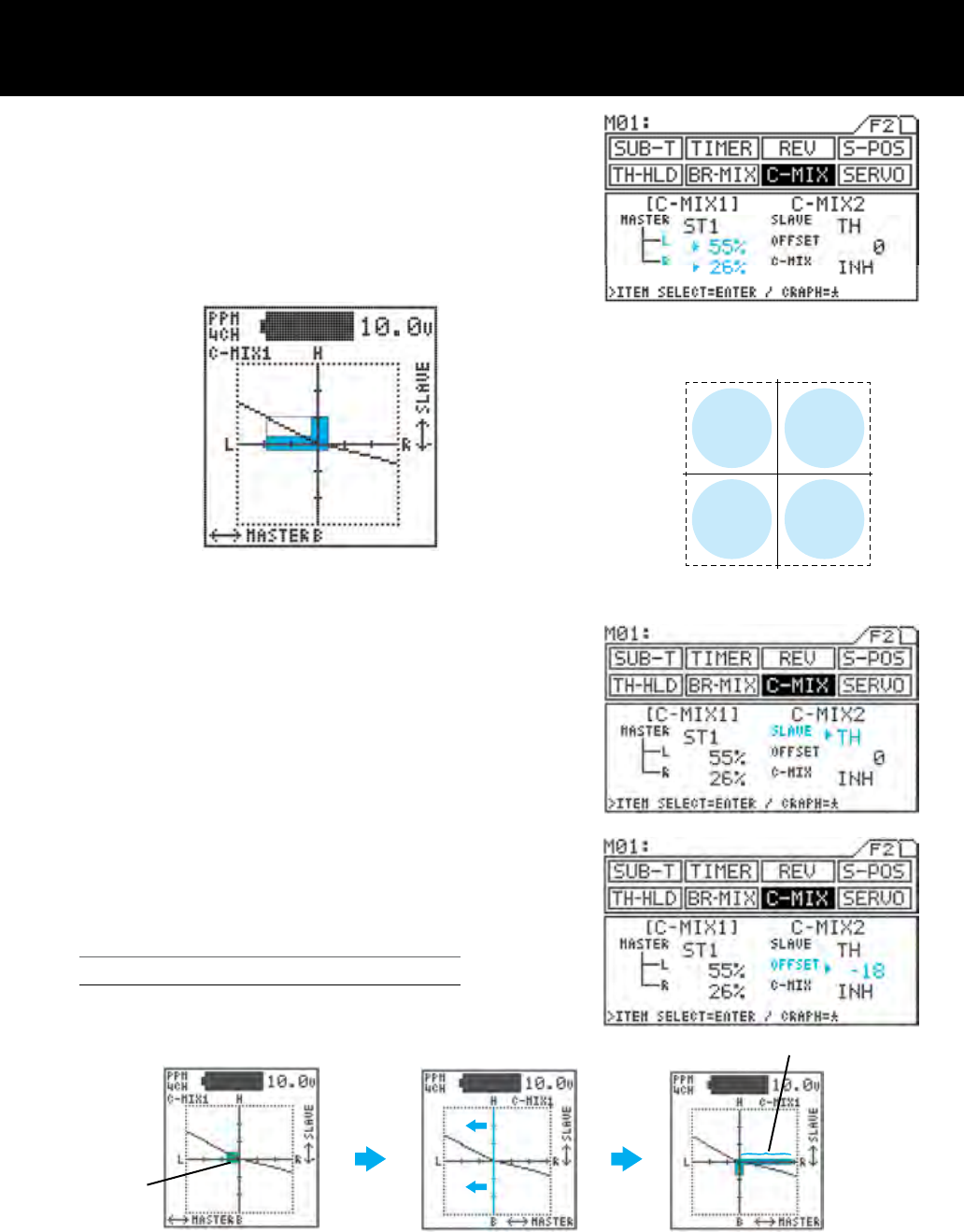
3) Setting the mixing level
<Left side, High side>
Move u to the right of L (or H) with the ENTER key, and then set the
mixing level by pressing the Inc.+ or Dec.- key.
<Right side, Brake side, Low side>
Move u to the right of R (or B or L) with the ENTER key, and then set
the mixing level by pressing the Inc.+ or Dec.- key.
The H key displays the graph in the in the constant
display area.
4) Setting the SLAVE channel
Move u to the right of SLAVE with the ENTER key,
and then select the SLAVE channel by pressing the
Inc.+ or Dec.- key.
* Setting range ST, TH, AUX, BR
* The AUX channel always becomes the slave of the
third channel, regardless of the ACT/INH setting of
3CH-BRAKE.
5) Setting the amount of OFFSET
Move u to the right of OFFSET with the ENTER key,
and then set the amount of offset by pressing the Inc.+
or Dec.- key.
Using the Offset Function
(1) Correcting Master 2 trim deviation using OFFSET
Graph display
for L side setting
(55%)
Bar graph of master
operation
Master is horizontal axis
Slave is vertical axis
Mixing level bar graph for slave
(Mixing level varies as indicated
according to slope of graph.)
Graph display
for R side setting
(26%)
* Adjust offset value in nega-
tive direction, moving vertical
axis to left and erasing bar
graph.
Master ST3,SLAVE TH Bar graph shows extent of
steering operation
* When trim deviation appears
in graph as shown above with
steering at neutral position.
* By adjusting to the point where
deviation disappears, the steer-
ing neutral position can become
the origin for mixing.
deviation
L side +%
graph R side -%
graph
L side -%
graph R side +%
graph
Page 41
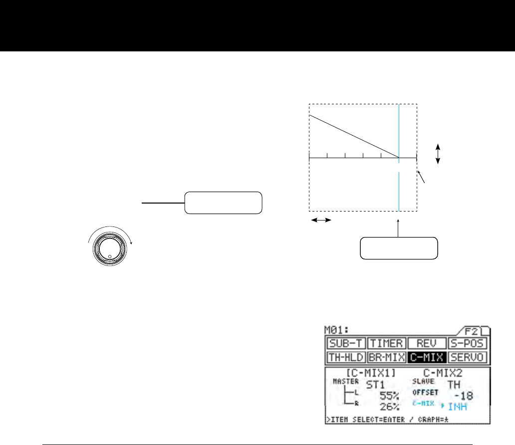
-150 -100 -50 0 50 100 150
MASTER
H
B
H L
H 50%
L 0%
MAX0
(DIAL)
SLAVE
(2) Adjusting the master mixing origin so that that no
mixing occurs when the dial (AUX) is turned fully to
the left, but maximum mixing occurs when it is turned
fully to the right.
6) Setting INH/ACT for C-MIX
Move u to the right of C-MIX with the ENTER key,
and then select INH or ACT by pressing the Inc.+
or Dec.- key.
IMPORTANT
- About the INH/ACT setting of C-MIX
The INH/ACT setting of C-MIX can be changed using the key assign switch as well as through the menus. Using
this function, adjustment is possible from any menu, C-MIX “ON” or “OFF” can be easily adjusted with the selected
switch even during operation.
NOTE
* When the slave and master are both on the same channel, mixing takes place within the channel itself, causing
the steering angle to increase for positive values, and to decrease for negative values. By switching mixing ON
and OFF, you may want to choose with desired feeling of the steering during the driving.
Since no operation occurs beyond 100
when the master channel is AUX1, this
can be set to 100.
This is set to 0% because no operation
results on the L side with an offset.
Page 42
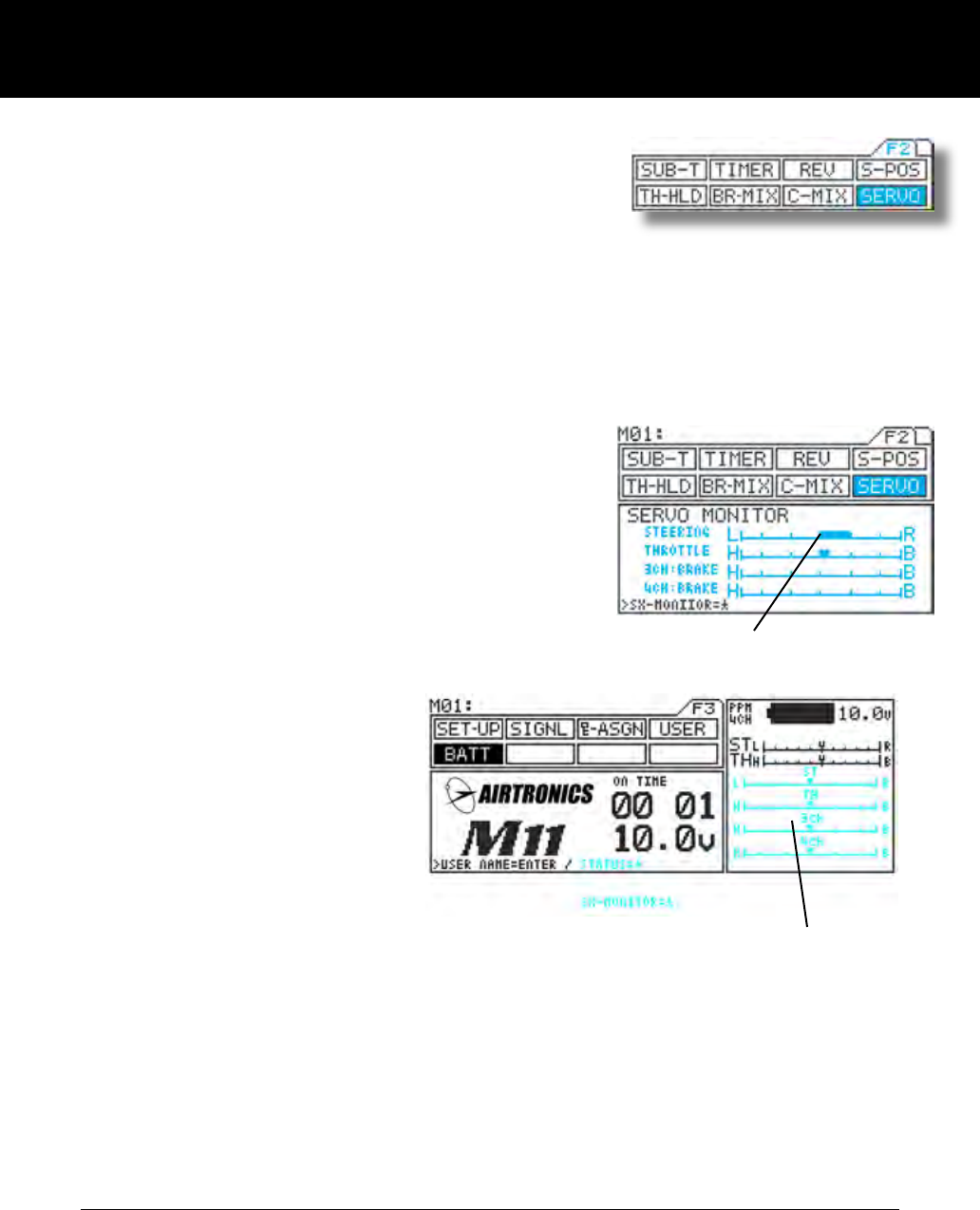
Servo Page F2 (SERVO)
* This function displays the output levels of the various channels in bar graph
form, allowing you to monitor model operation in a virtual manner.
* Using this feature while making function setting can make it easier to under-
stand adjustments.
* The graph can be displayed in the constant display area, allowing it to be
viewed while making settings of other features.
(Some menus cannot be displayed.)
1) Using the function select keys, move the cursor to
SERVO.
2) Opening the constant display area
You can open the constant display area from any
menu by pressing the H key. Pressing the key a
second time returns the display to normal.
* Menus you can open
F1 F2
(1)D-RATE (1)SUB-T
(2)EPA *(2)TIMER
(3)EXP (3)REV
(4)ARC (4)S-POS
(5)SPEED (5)HOLD
(6)ALB (6)BR-MIX
(7)TR-CLL (7)SERVO
* The graph cannot be displayed from the [LAP] menu.
NOTE
* REV operation is not reected in the servo monitor. Indication of the graph only shows the direction of the input
control such as wheel and trigger movement.
Example)
BATT menu
Servo monitor display
Constant display area
Bar graph display
Page 43
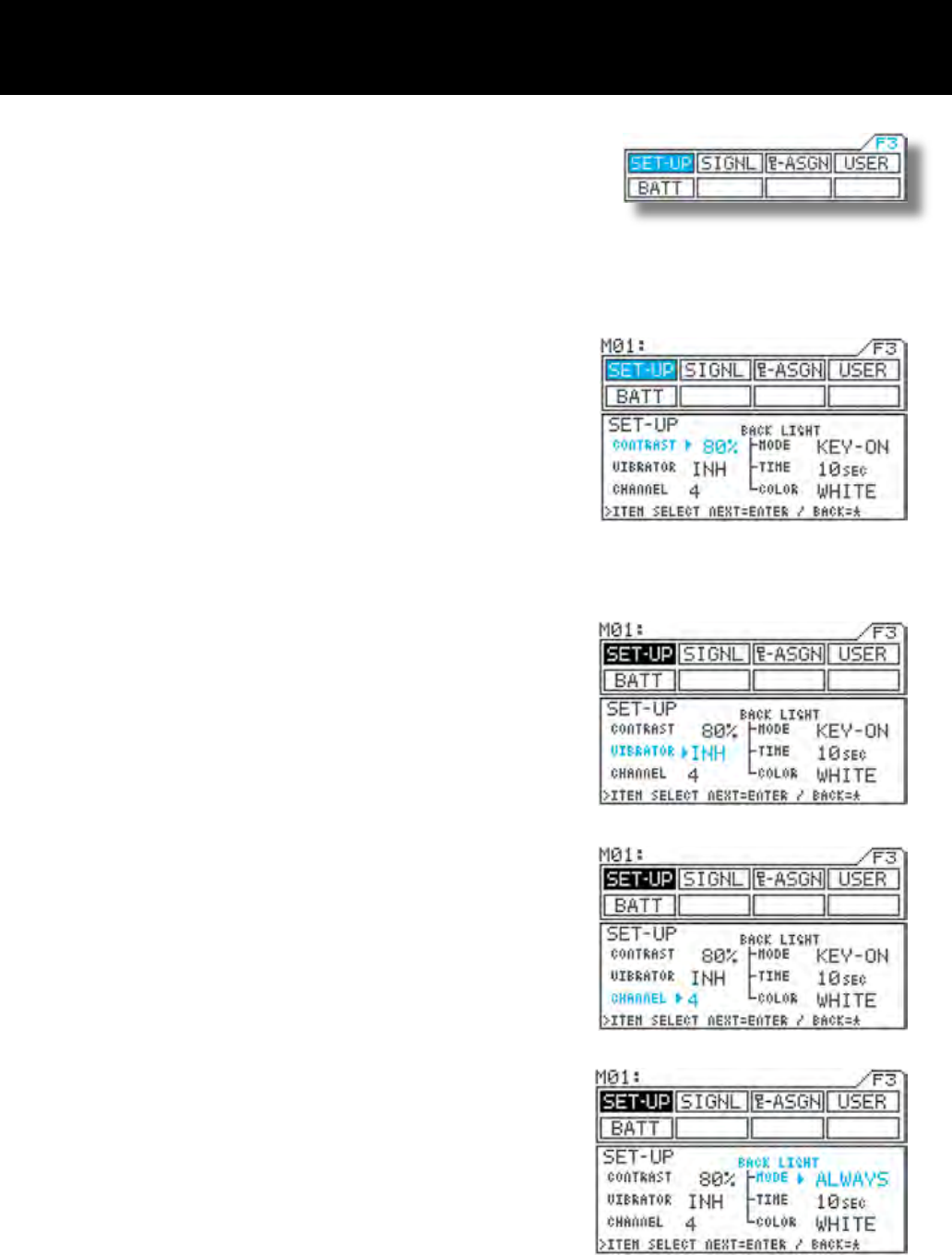
Set-up Page F3 (SET-UP)
* This section explains how to adjust the LCD contrast (darkness and light-
ness), turn the vibrator ON/OFF, and select between 2CH/4CH, backlight
ON/OFF/Auto OFF, backlight color set as blue or white.
1) Using the function select keys, move the cursor to
SET-UP.
2) CONTRAST setting
Move u to the right of CONTRAST with the ENTER
key or H key, and then adjust LCD contrast (dark-
ness) by pressing the Inc.+ or Dec.- key.
* Setting range 0% to 100%
* Standard setting 80%
3) Setting INH/ACT for VIBRATOR
Move u to the right of VIBRATOR with the ENTER
key or H key, and then select INH or ACT for the
vibrator by pressing the Inc.+ or Dec.- key.
* When ACT is selected, the vibrator buzzes at the
same time as timer alarm or the battery alarm
emit. It also buzzes when the Main power is turned
on.
4) Making the CHANNEL setting
Move u to the right of CHANNEL with the ENTER
key or H key, and make the channel selection by
pressing the Inc.+ or Dec.- key.
* 2CH ch1 Steering (ST)
ch2 Throttle (TH)
* 4CH ch1 Steering (ST)
ch2 Throttle (TH)
ch3 AUX or brakes (BR)
ch4 Brakes (BR)
5) Making the BACK LIGHT setting
<MODE>
Move u to the right of MODE with the ENTER key
or H key, and then select the mode by pressing the
Inc.+ or Dec.- key.
* KEY-ON-ON The backlight goes OFF when
the time set for TIME elapses
without any menu key opera-
tion.
* ALWAYS The backlight remains con-
stantly ON.
* OFF The backlight remains con-
stantly OFF.
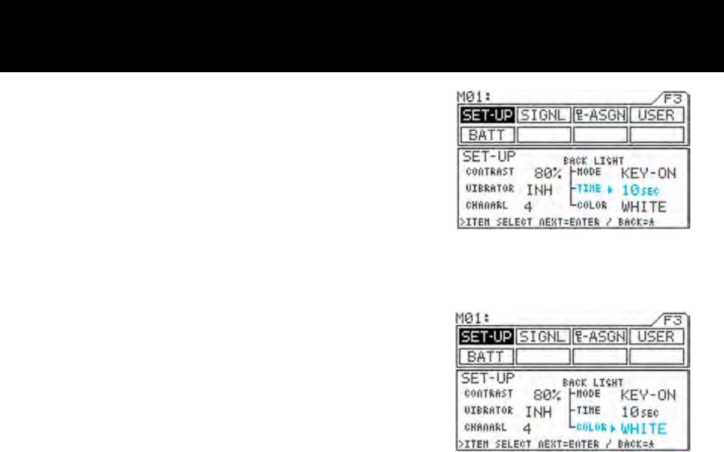
Page 44
<TIME>
Move u to the right of TIME with the ENTER key or
H key, and then set the time by pressing the Inc.+
or Dec.- key.
* This will not appear unless MODE is set to KEY-
ON.
* Setting range 1SEC to 30SEC
* Standard setting 10SEC
<COLOR>
Move u to the right of COLOR with the ENTER
key or H key, and then select the backlight color by
pressing the Inc.+ or Dec.- key.
* WHITE White backlight
* BLUE Blue backlight
Page 45
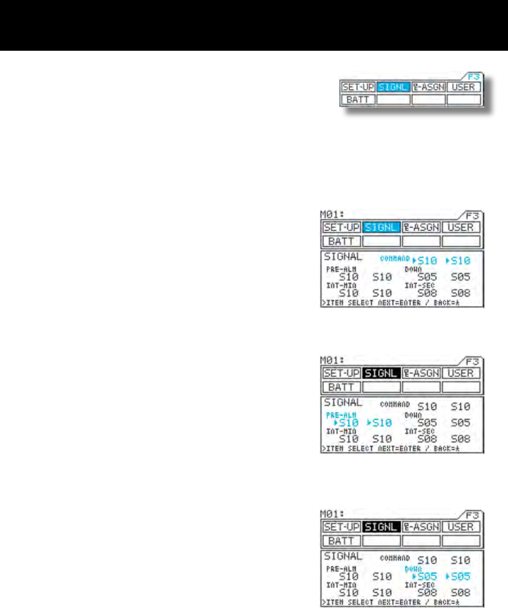
Audio Signal Sound Page F3 (SIGNL)
* This function allows you to set the key operation tone and alarm tones to be
set independently in different tonal scale.
* Tonal scale of the each key operation or alarm can be set differently on two
parts. Meaning, Tonal scale can be set separately for the rst half and last half
tones.
* Tone can be selectable among 10 tones, providing a total of 100 pattern com-
binations for the rst half and last half of signals.
1) Using the function select keys, move the cursor to
SIGNL.
2) Command signal (COMMAND) tone setting
Move u to the right of COMMAND with the ENTER
key or H key, and then set the tone for the rst half
of the signal by pressing the Inc.+ or Dec.- key.
Next, move u one position to the right with the EN-
TER key, and then set the tone for the last half of the
signal by pressing the Inc.+ or Dec.- key.
* Setting range S01 to S10 and MUTE
(silent)
* Standard setting First half: S10,
Last half: S10
* The command signal sounds when menu keys
are pressed.
3) Making pre-alarm (PRE-ALM) tone settings
Move u to the right of PRE-ALM with the ENTER
key or H key, and then set the tone for the rst half
of the signal by pressing the Inc.+ or Dec.- key
Next, move u one position to the right with the EN-
TER key, and then set the tone for the last half of the
signal by pressing the Inc.+ or Dec.- key.
* Setting range S01 to S10 and MUTE
(silent)
* Original setting First half: S10,
Last half: S10
* The pre-alarm signal is used with the lap timer.
4) Making down alarm (DOWN) tone settings
Move u to the right of DOWN with the ENTER key
or H key, and then set the tone for the rst half of the
signal by pressing the Inc.+ or Dec.- key.
Next, move u one position to the right with the EN-
TER key, and then set the tone for the last half of the
signal by pressing the Inc.+ or Dec.- key.
* Setting range S01 to S10 and MUTE
(silent)
* Standard setting First half: S05,
Second half: S05
* The down alarm signal is used with the down
timer.
Page 46
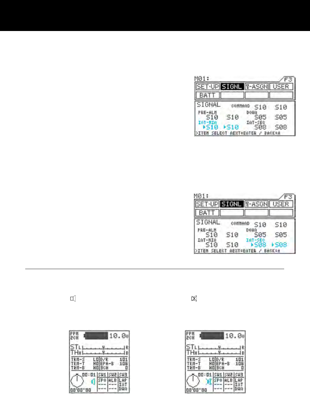
5) Making interval minute alarm (INT) tone settings
Move u to the right of INT-MIN with the ENTER key
or H key, and then set the tone for the rst half of the
signal by pressing the Inc.+ or Dec.- key.
Next, move u one position to the right with the EN-
TER key, and then set the tone for the last half of the
signal by pressing the Inc.+ or Dec.- key.
* Setting range S01 to S10 and MUTE
(silent)
* Standard setting First half: S10,
Last half: S10
* The interval minute alarm is used with the minutes
portion of the interval timer.
6) Making interval seconds alarm (INT) tone settings
Move u to the right of INT-SEC with the ENTER key
or H key, and then set the tone for the rst half of the
signal by pressing the Inc.+ or Dec.- key.
Next, move u one position to the right with the EN-
TER key, and then set the tone for the last half of the
signal by pressing the Inc.+ or Dec.- key.
* Setting range S01 to S10 and MUTE
(silent)
* Standard setting First half: S08,
Second half: S08
* The interval seconds alarm is used with the second
portion of the interval timer.
IMPORTANT
- If two signals overlap, they sound as a single tone. The longer tone may not sound.
- If you do not want a signal tone, select MUTE for both the rst and last halves of the tone. If you mute only half
the tone, the half will sound.
- The buzzer icon displayed in the constant display area changes to if both halves of the command setting
are muted.
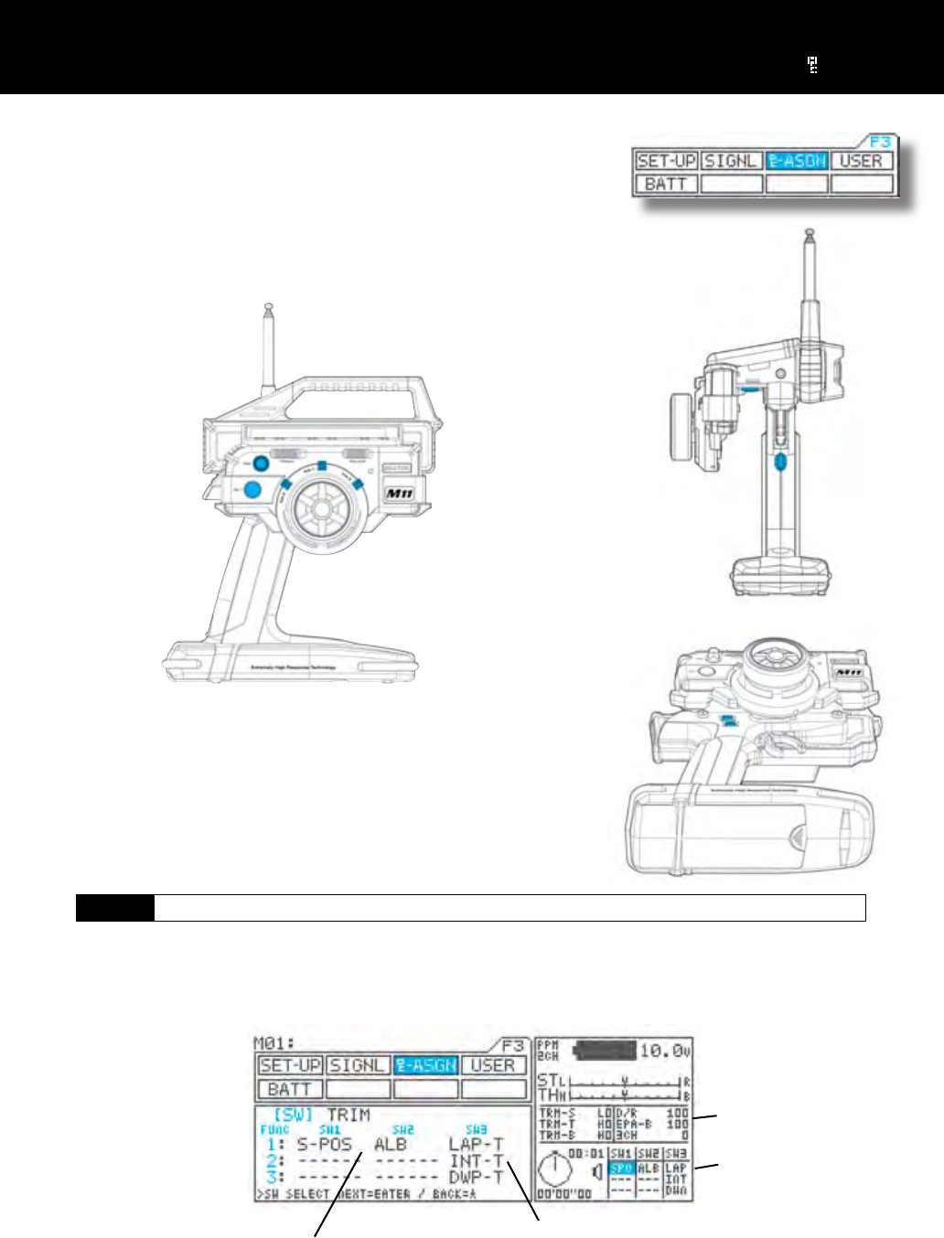
Page 47
Switch / Trim Assignment Page F3 ( -ASGN)
* Functions and trim settings (adjustments to function settings) can be freely
assigned to SW1-SW3, trimmers TRM1-TRM5, and the dial control on the
transmitter.
* Locations of switches and trimmers
[SW] Key Assign Switch
* ON/OFF control of various functions can be assigned to SW1-SW3, making it easy to use those functions during
operation.
* Up to three functions (FUNC1-FUNC3) can be assigned to a single switch, allowing all of those functions to be
controlled at once.
* Functions originally assigned to switches at the factory
TRM1: Steering trim SW1: Starting position
TRM2: Throttle trim SW2: Anti-lock braking
TRM4: Dual rate SW3: Timer
TRM5: End point adjust, brake
When the function is turned
ON, character be displayed .
Function status is also
displayed in the constant
display area.
Here, LAP-T, INT-T, and
DWP-T can all be turned
ON/OFF together.
Up to three functions can
be assigned to a single
switch.
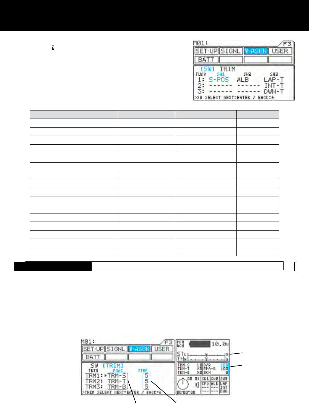
Page 48
[TRIM] Trim Assignment
Function Menu screen Constant display area Factory default
Exponential steering EXP-ST EXS
Exponential throttle EXP-TH EXT
Adjustable rate control, steering ARC-ST ARS
Adjustable rate control, throttle ARC-TH ART
Speed steering SPD-ST SPS
Speed braking SPD-BR SPB
Anti-lock braking ALB ALB [SW2]
Traction control TR-CTL TRC
Lap timerl LAP-T LAP [SW3]
Interval timer INT-T INT [SW3]
Down timer DWN-T DWN [SW3]
Starting position S-POS SPO [SW1]
Starting position, brake lock BR-LCK BRL
Throttle hold TH-HLD HLD
Compensation mixing 1 C-MIX1 CX1
Compensation mixing 2 C-MIX2 CX2
1) Using the function select keys, move the cursor to
[SW] in -ASGN.
2) Using the H key or the ENTER keys, move u to the
switch to be assigned, and then assign functions to
the switch by pressing the Inc.+ or Dec.- key.
* Assignable functions
[TRIM] Key Assign Trim
* Setting of function can be varies by using trimmers TRM1 to TRM5 and the dial.
* The size of the STEP can be set and each setting width can be changed by pressing a key.
* Functions can be freely assigned to any of 6 positions, allowing you to choose the controls that are best suited to
your situation.
* The values of function settings made using key assign trim can be displayed in the constant display area, allowing
them to be conrmed from any menu.
Settings also appear
Number of steps (size of change)
Function setting
Status of settings is also
displayed in the constant
display area.
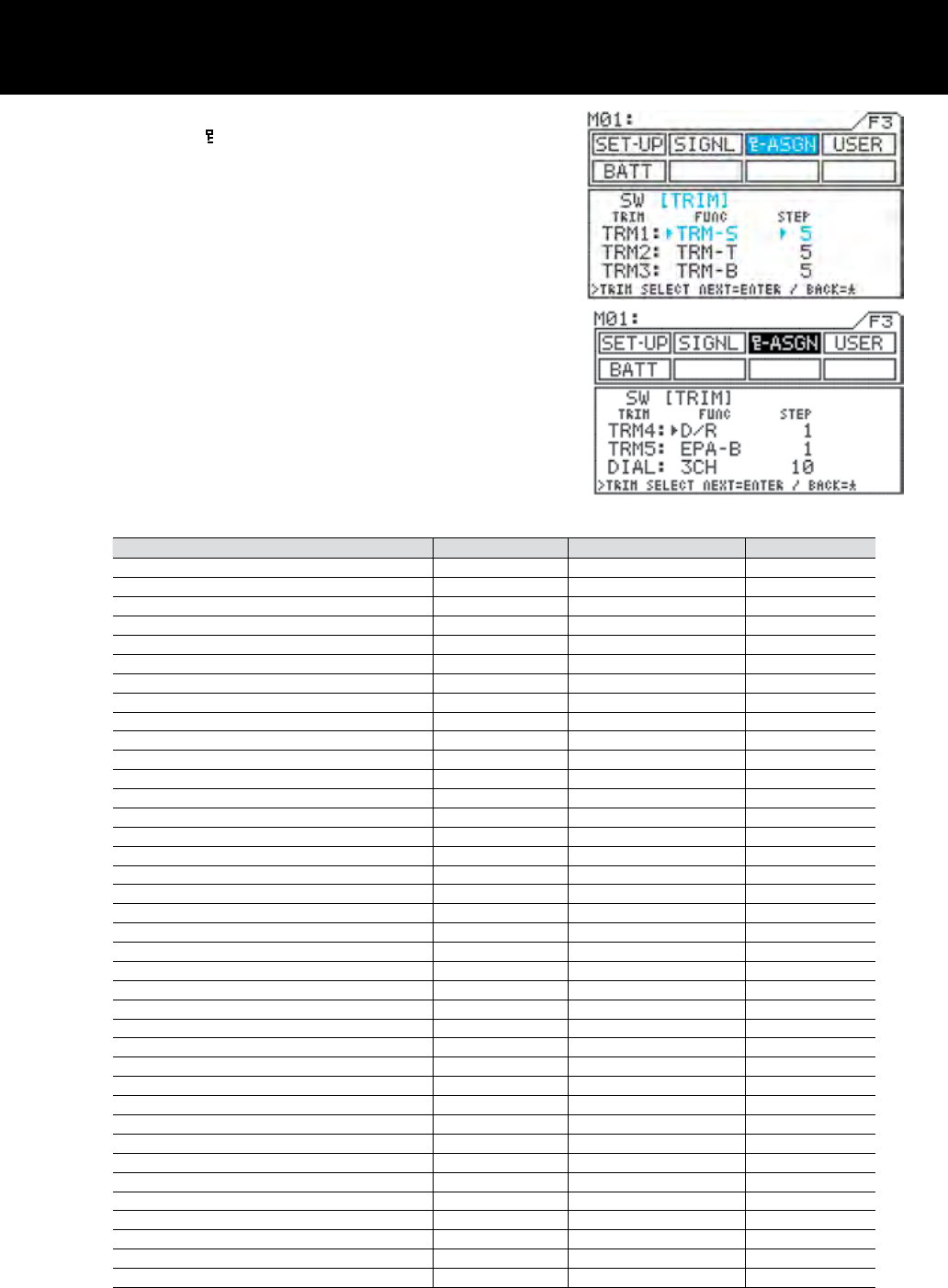
Page 49
1) Using the function select keys, move the cursor to
[TRIM] in -ASGN.
2) Function selection
Using the H key or the ENTER keys, move u to the
trimmer function to be selected, and then select a
function by pressing the Inc.+ or Dec.- key.
3) Setting the number of steps
Using the H key or the ENTER keys, move u to
the STEP for the trimmer you want to adjust, and
then set the number of steps by pressing the Inc.+
or Dec.- key.
* The number of steps determines the amount of
trim that is applied for one click of the trimmer
switch.
* Selectable functions and step ranges
Function Menu screen Constant display area Factory default
Dual rate D/R 1 - 10 [SW4]
End point adjustment, brake EPA-B 1 - 10 [SW5]
Exponential steering EX-S 1 - 10
Exponential throttle, high EX-H 1 - 10
Exponential throttle, brake EX-B 1 - 10
Adjustable rate control, steering rate AR-S-R 1 - 10
Adjustable rate control, steering point AR-S-P 1 - 10
Adjustable rate control, throttle high rate AR-H-R 1 - 10
Adjustable rate control, throttle brake rate AR-B-R 1 - 10
Adjustable rate control, throttle high point AR-H-P 1 - 10
Adjustable rate control, throttle brake point AR-B-P 1 - 10
Speed steering forward SP-S-F 1 - 10
Speed steering return SP-S-R 1 - 10
Speed steering point SP-S-P 1 - 10
Speed brake forward SP-B-F 1 - 10
Speed brake point SP-B-P 1 - 10
Anti-lock braking point ALB-PT 1 - 10
Anti-lock braking stroke ALB-ST 1 - 10
Anti-lock braking lag ALB-LG 1 - 10
Anti-lock braking speed ALB-SP 1 - 10
Traction control, traction TRC 1 - 10
Traction control, delay TRC-DY 1 - 10
Traction control, point TRC-PT 1 - 10
Starting position SPOS 1 - 10
Throttle hold HLD 1 - 10
Brake mixing delay, 2CH BM-2CH 1 - 10
Brake mixing delay, 3CH BM-3CH 1 - 10
Brake mixing delay, 4CH BM-4CH 1 - 10
Compensation mixing 1, offset CX1-OF 1 - 10
Compensation mixing 1, high CX1-Hi 1 - 10
Compensation mixing 1, low CX1-Lo 1 - 10
Compensation mixing 2, offset CX2-OF 1 - 10
Compensation mixing 2, high CX2-Hi 1 - 10
Compensation mixing 2, low CX2-Lo 1 - 10
Steering trim TRM-S 1 - 10 [TRM1]
Throttle trim TRM-T 1 - 10 [TRM2]
Brake trim TRM-B 1 - 10
3CH (AUX) 3CH 1 - 10,20,50,100,200
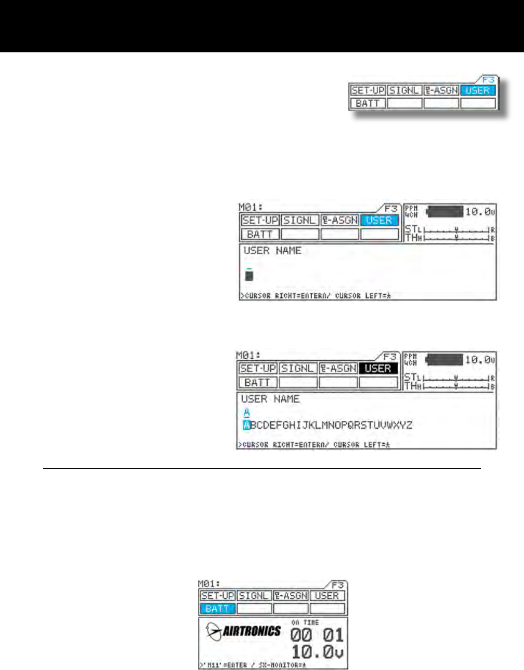
Page 50
User Name Page F3 ( USER)
Joe Driver
1) Using the function select keys, move the cursor
to USER.
2) Using the H key or the ENTER key, move the
cursor (“_”) to the point when you want to enter
text.
3) Select a character by pressing the Inc.+ or Dec.-
key.
* Setting range A – Z, a – z, 0 – 9, symbols,
space
4) Repeat steps 2) and 3) for each subsequent
character.
You can put a user name in the M11. Up to 12 letters, numbers and or symbols.
The user name will stay in the transmitter even if you reset model memory.
NOTE
* Group of characters can be ipped in the sequence A a 0 ! space by simultaneously pressing the
Inc.+ and Dec.- keys.
* When entering a character in a position occupied by a space, Group of the preceding character can be selected
by rst pressing the Dec./+ key. This is useful when entering several characters from the same group.
* Under the BATT menu, indication of the display can be switch between display of the M11 logo and the user name
by using the ENTER key.
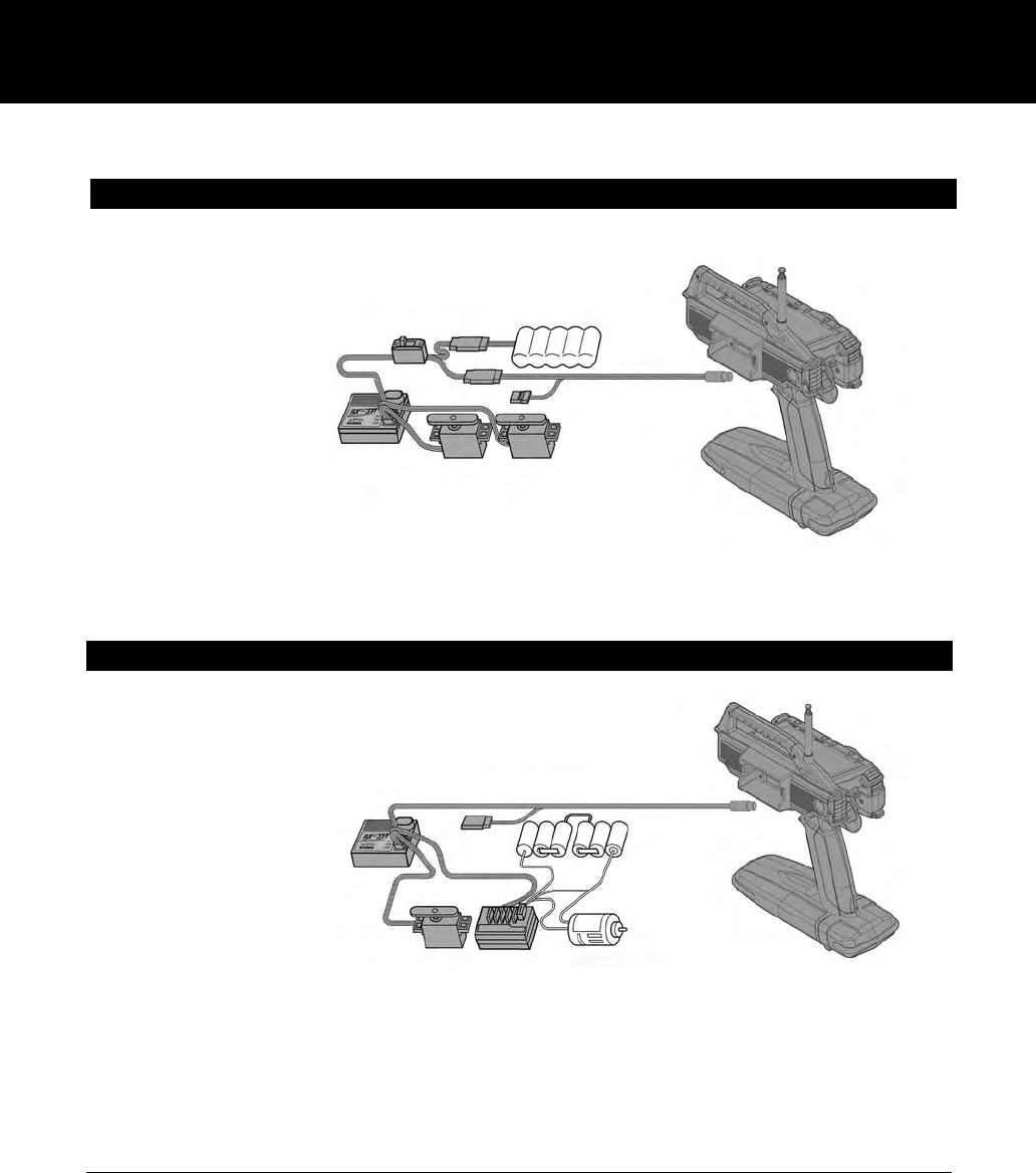
Page 51
Direct Servo Controller DSC Cord
Using the DSC cable with DSC switch harness equipped on Gas powered type models
1) Connect the supplied DSC cable to the DSC jack at the opposite side of
the wheel of the M11.
* The display appears.
Using the DSC Switch Harness with an FET Speed Controller
1) Connect the supplied DSC cable to the DSC jack at the opposite side of
the wheel of the M11.
* The display appears.
In order to check the model vehicle’s Linkage during the race or at the situation when the radio transmission is pro-
hibited, such setting arrangement can be done by using the DSC cable.
CAUTION
- Never turn on the power switch on the transmitter while using the DSC harness.
[ RF activate for radio transmission which may occur trouble to others. ]
- When using the DSC cable, connect the power battery of the E/P car and/or connect the receiver battery to receiver
for G/P models.
- When using the DSC cable, be sure that the transmitter battery is installed.
- After using the DSC cable, be sure to disconnect the DSC cable at both end.
(* Prevent from possible risk from other radio transmission, remove the receiver crystal.)
2) Connect the DSC Cable’s male connector to the Battery/DSC channel on the receiver.
3) Turn on the Display switch at M11 thence turn on the Power at ESC ‘s switch harness.
4) Ready for DSC operation.
(* Prevent from possible risk from other radio transmission, remove the receiver crystal.)
2) Connect the DSC cable (female connector) to the charging connector (male) on the DSC switch harness.
3) Turn on the Display switch at M11 thence turn on the power at DSC switch harness.
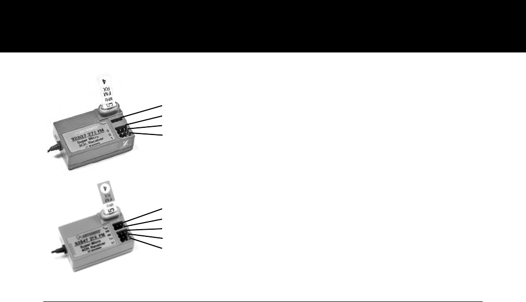
Page 52
CAUTION
Use only genuine Airtronics FM Crystals.
Using of crystals other than those specied may result in frequency errors and possible runaway operation.
There is a danger of runaway operation, if connectors shake loose while driving. Make sure that receiver, servo, and-
switch connectors are securely tted.
A danger of runaway operation exists with shorter antennas, due to reduced receptivity. Do not cut any length of antenna
wire.
The receiver susceptible to vibration, shock and moisture. Take appropriate measures to protect against vibration and
water. Failure to take appropriate measures could result in runaway operation or to damage to the receiver.
Keep the receiver antenna away from motors, battery, and ESC and make sure that antenna stick out from the model
vehicle vertically.
When installing the receiver, don’t let it come in contact with any carbon or metal chassis.
Contact between metal parts mounted on a model can result in electrical noise, adversely affecting receiver performance
and possibly resulting in runaway operation or damaged to your model vehicle.
With electrically-powered models, be sure to t the motor with a noise suppression capacitor. Without a noise suppression
capacitor, excessive noise generation can cause runaway operation. And/or result of damage to the model vehicle.
Use rubber anti-vibration absorbers with servos. Direct transmission of engine vibration to servos can cause servo failier
and possibly result in runaway operation with damaging your model vehicle.
The manufacturer disclaims all responsibility for damages resulting from use of components other than genuine
AIRTRONICS/SANWA components.
The M11 can be switched between 2ch and 4ch operation.
Note that 4ch operation is not possible when using the 92836 or 92837 receivers were being used.
Receiver Connection and Installation
Connector Locations on the receiver
B/DSC
AUX2
AUX1
TH
ST
Battery / Direct Servo Controller
Channel 4
Channel 3
Channel 2 (Throttle)
Channel 1 (Steering)
B/DSC
AUX1
TH
ST
Battery / Direct Servo Controller
Channel 3
Channel 2 (Throttle)
Channel 1 (Steering)
92837Z FM 3 Ch (27 MHz)
92827Z FM 3 Ch (75 MHz)
92847Z FM 3 Ch (27 MHz)
92846Z FM 3 Ch (75 MHz)
(3 Channel Receiver)
(4 Channel Receiver)

Page 53
Troubleshooting
Symptom Cause Remedy
Does not Transmit Batteries low or not fully
charged. Replace or charge batteries
Power sometimes goes off Intermittent connector
contact. Contact Airtronics for service.
Alarm does
not stop S-POS switch is in the ON
position. Turn S-POS switch to the OFF position.Alarm gives off continu-
ous double beep.
Alarm gives off a series
of beeps.
Alarm gives off a periodic
double beep.
Battery voltage low. Replace or charge transmitter batteries.
The interval timer is ON. Check the INT timer.
No key sound when press keys. Command signals are
disabled. Check command signal settings.
No change in display when pressing
keys Key lock switch is ON Turn lock key switch OFF.
Servo movement is slow
A negative value is set in the
servo speed. Check servo speed settings
Low battery Replace or charge transmitter batteries.
Linkage stiff Adjust linkage to work freely.
Left and right steering angles are differ-
ent even if settings are the same. Trim or Sub Trim not cen-
tered Align trim and Sub Trim.
Servo will not move to the end of its
range. D-RATE and EPA settings
are too large. Reset linkage on the servo for more travel from
servo and reset settings.
Servo does not move when using trim. Trim is outside of operational
range. Reset trim to 0 and center the servo horn and link-
age on servo.
Lap timer and interval timer do not func-
tion Timers are set in the OFF
position Turn timers ON.

Page 54