Alarm Lock ArchiTech_Type_2_WI2090A.07_INST Archi Tech_ By Networx_: For Mortise Locks Using Surface Mounted Networx Control Units Tech Type 2 WI2090A.07 INST
User Manual: Alarm Lock ArchiTech_ by Networx_: For Mortise Locks Using Surface-Mounted Networx Control Units Installation Manuals
Open the PDF directly: View PDF ![]() .
.
Page Count: 16
1
ArchiTech Mortise Lock & Surface-Mounted Networx Control Unit Mounting and Installation Instructions
ArchiTech™ by Networx™
FOR MORTISE LOCKS USING SURFACE-MOUNTED NETWORX CONTROL UNITS
MOUNTING AND INSTALLATION INSTRUCTIONS
© NAPCO Security Technologies, Inc. 2015 WI2090A 05/15
DESCRIPTION
These instructions detail the hardware installation procedure for the ArchiTech mortise door locks using the Surface-
Mounted Networx Control Units for hollow metal and solid wood doors.
Installation instructions for the Door Contact Sensor, Door Contact Magnet (installed in the door jamb) and the
Oval and Rectangular Proximity Readers are also included.
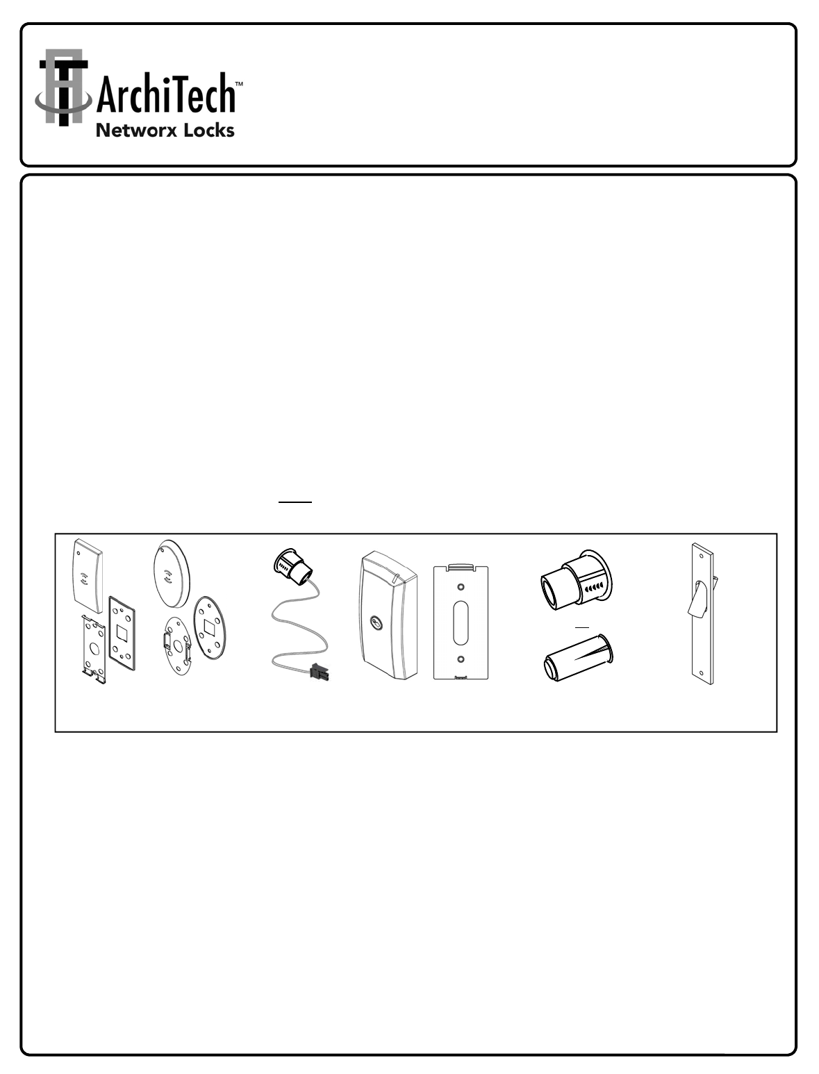
PARTS OVERVIEW
For reference, the images in Fig. A below display each component (not to scale). In addition to the various screws
included with your mortise lock, please be aware that two types of Proximity Readers are available (either Oval or
Rectangular) but only one type is included with your lock. Furthermore, one of two types of Door Contact
Magnets (installed in door jamb) are included (either 3/8" or 3/4" diameter). We recommend taking the time to
read through these instructions, find and familiarize yourself with each component before you begin your installation.
As detailed in the instructions that follow, the Proximity Reader wire, the Door Contact Sensor wire and the Mortise
Lock Motor Wire are routed through the door and are plugged into the Surface-Mounted Networx Control
Unit. The Mortise Lock Motor Wire can easily be routed within hollow metal doors. For solid wood doors, a
Mortise Drill Jig (part #N95I1DJ) must be used to drill a hole pathway within the solid wood door to route the
Mortise Lock Motor Wire.
REQUIRED TOOLS
In addition to the standard door prep kit tools used to install a mortise lock into a metal or wood door (Phillips and flat
head screwdrivers, etc.), you will need: A small level, and the following drill bit sizes: 5/8", 3/8", 3/4" and 7/64".
FIG. A: OVERVIEW OF BASIC PARTS (NOT TO SCALE)
OVAL AND RECTANGULAR
PROXIMITY READER COVERS AND
MOUNTING COMPONENTS
MORTISE DRILL JIG
(N95I1DJ)
(SOLID WOOD DOORS ONLY)
DOOR CONTACT
MAGNET
(TWO TYPES)
OR
DOOR
CONTACT
SENSOR
"SURFACE-MOUNTED" NETWORX
CONTROL UNIT
AND ITS MOUNTING PLATE
ArchiTech Mortise Lock & Surface-Mounted Networx Control Unit Mounting and Installation Instructions
2
DOOR PREP: INITIAL STEPS
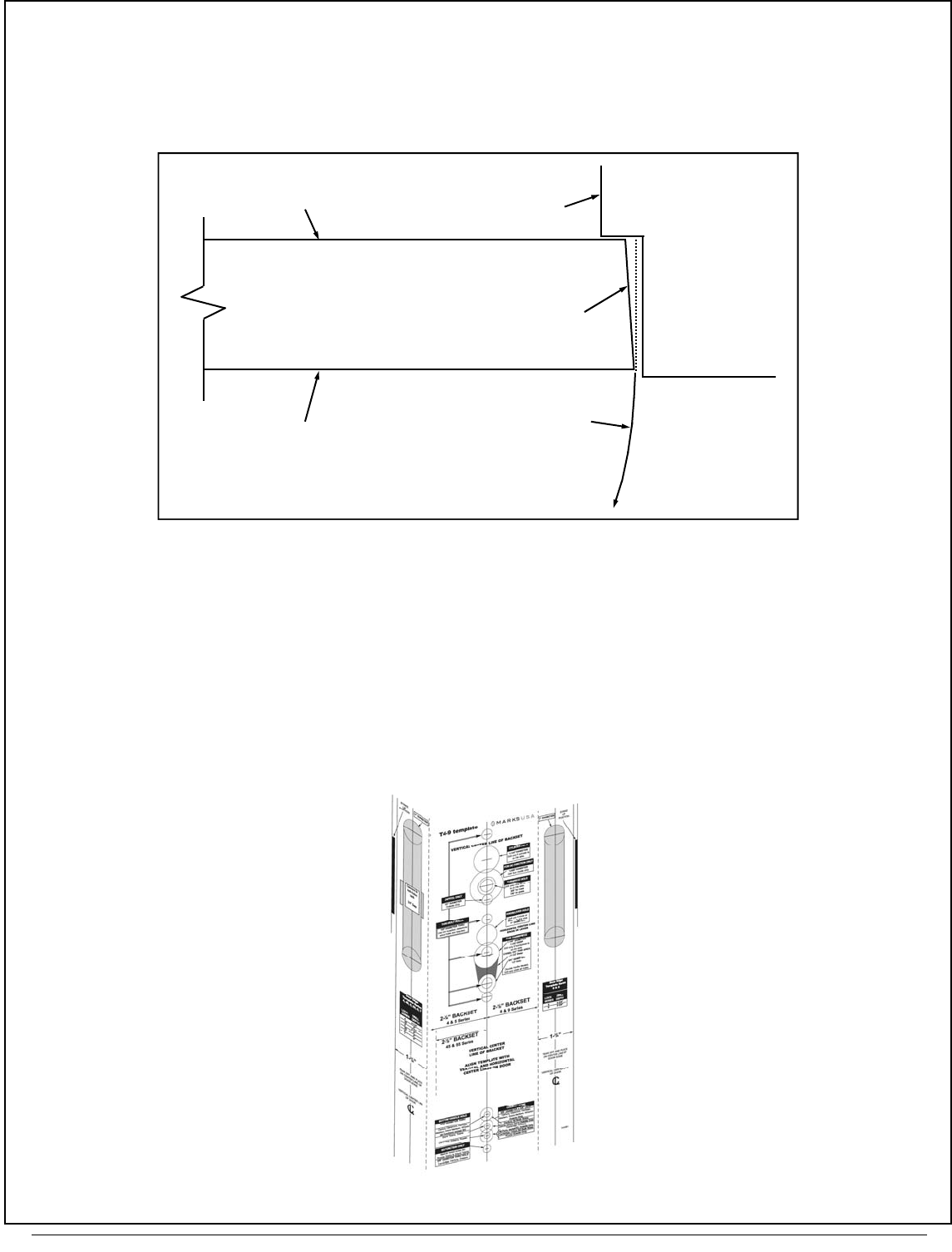
1. INSPECT THE DOOR BEVEL
Inspect the door for a bevel and, if beveled, determine which side is "longer" in width and which side is "shorter" in
width (see "top view" example in Fig. 1). For beveled doors, be sure to use the correct marks printed on the template
for the correct length of the outside door surface (either the "long" or "short" side of the door).
2. PREP DOOR FOR MORTISE LOCK
If not done already, use standard door prep kit tools and the instructions included with the mortise lock to prep the
door and door jamb as required. These include mortising the door edge for the latch plate and mortising the door
jamb for the strike plate.
Do not install the lock hardware yet.
DOOR 3½° bevel
Door Stop
Arc of door swing
Jamb
"Shorter side of
door"
"Longer side of
door"
FIG. 1: EXAMPLE OF BEVELED DOOR (TOP VIEW)
FIG. 2: USE TEMPLATE PROVIDED
3
ArchiTech Mortise Lock & Surface-Mounted Networx Control Unit Mounting and Installation Instructions
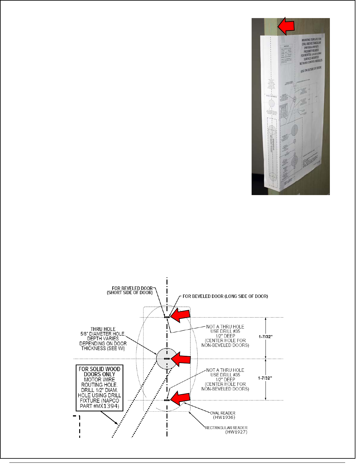
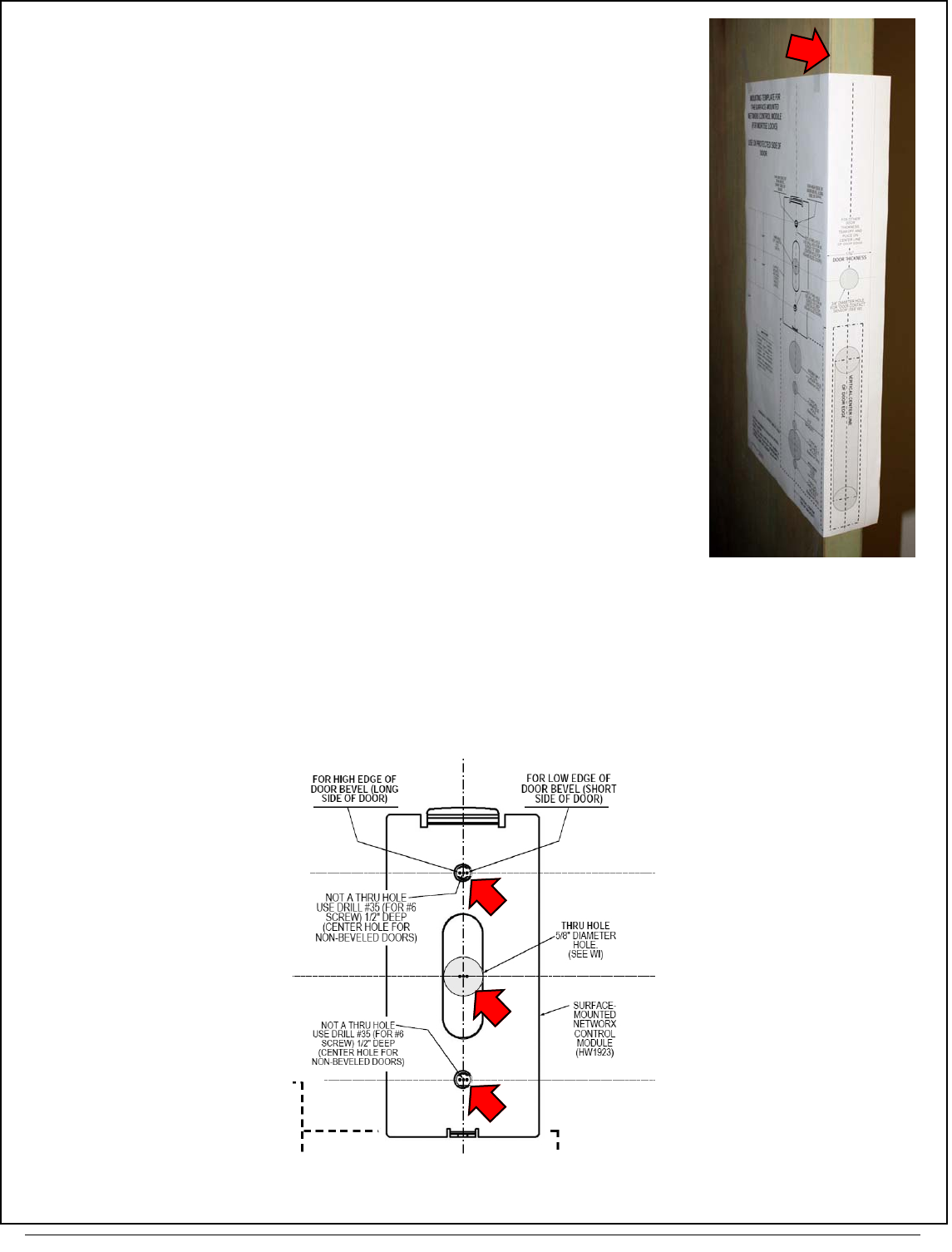
3. TAPE ON DOOR: "PROXIMITY READER" TEMPLATE (WI2102)
Remember, the Proximity Reader is always located on the outside
("unprotected" side) door surface.
Fold and place the template (WI2102) on the outside door edge (see arrow
in Fig. 3 for an example). Align the template with the "HORIZONTAL CEN-
TER LINE OF LEVER" as shown on the template. Tape the template in
place.
4. MARK TEMPLATE "PROXIMITY READER" HOLES
On the outside door surface, mark the two holes for the Proximity Reader mounting screws.
Mark the center of the 5/8" Diameter Thru-Hole (used for the Mortise Lock Motor Wire, Proximity Reader and Door
Contact Sensor wires). Do NOT remove the template yet.
TIP: Take special notice of this 5/8" Diameter Thru-Hole, as it is an essential hole for this installation and is ref-
erenced several times throughout these instructions.
FIG. 4. EXAMPLE CLOSE UP OF WI2102 TEMPLATE FOR THE "PROXIMITY READER"
FIG. 3: EXAMPLE OF OUTSIDE DOOR
EDGE (ARROW)
ArchiTech Mortise Lock & Surface-Mounted Networx Control Unit Mounting and Installation Instructions
4
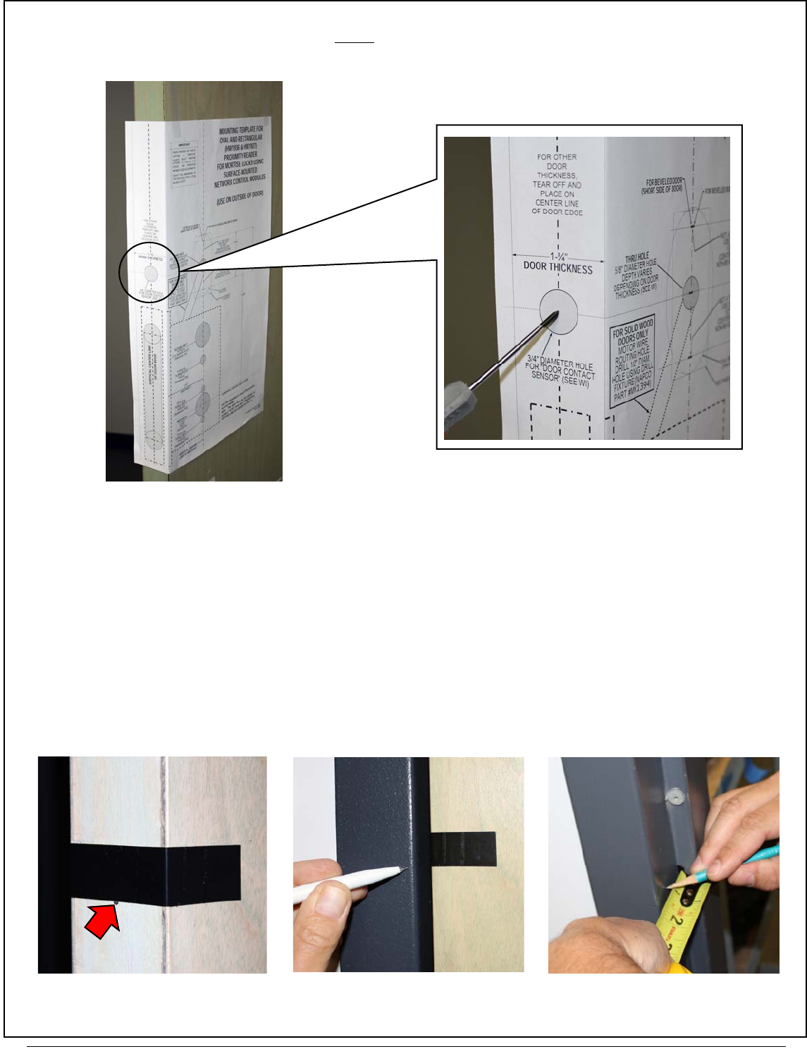
5. MARK TEMPLATE "DOOR CONTACT SENSOR" HOLE
Mark the 3/4" Door Contact Sensor hole in the center edge of the door (adjust for the door thickness).
Carefully remove the template.
6. MARK "DOOR CONTACT MAGNET" ON JAMB
The Door Contact Magnet must be installed in the door jamb such that when the door is closed, the Door Contact Sen-
sor is located directly opposite the Magnet. Install as follows:
6A. Open the door and temporarily place a piece of tape across the center of the mark made for the Door Contact
Sensor in the previous step. This tape signifies the height (from the floor) of the Door Contact Sensor.
6B. Close the door. Transfer this height to the door jamb with a light pencil mark.
6C. Determine the center location on the jamb directly opposite the Door Contact Sensor when the door is closed.
Open the door and measure the distance from the door edge to the center of the Door Contact Sensor (0.875"
or ⅞"). Transfer this distance to the door jamb, measured from the door stop.
FIG. 6B: CLOSE DOOR AND
TRANSFER HEIGHT TO JAMB
FIG. 6A: TAPE SIGNIFIES
"HEIGHT FROM FLOOR" FIG. 6C: LOCATE MAGNET IN JAMB
CENTERED DIRECTLY OPPOSITE THE
SENSOR WHEN DOOR IS CLOSED
FIG. 5: DOOR CONTACT SENSOR HOLE
ON DOOR EDGE
FIG. 5A: HOLE LOCATION DEPENDS ON
DOOR THICKNESS
5
ArchiTech Mortise Lock & Surface-Mounted Networx Control Unit Mounting and Installation Instructions
7. TAPE ON DOOR: "SURFACE-MOUNTED NETWORX CONTROL UNIT"
TEMPLATE (WI2103)
The Surface-Mounted Networx Control Unit (see Fig. A on page 1) is al-
ways mounted on the inside ("protected" side) door surface.
Fold and place the template (WI2103) on the inside door edge. Align the
template with the "HORIZONTAL CENTER LINE OF LEVER" as shown on
the template. Tape the template in place.
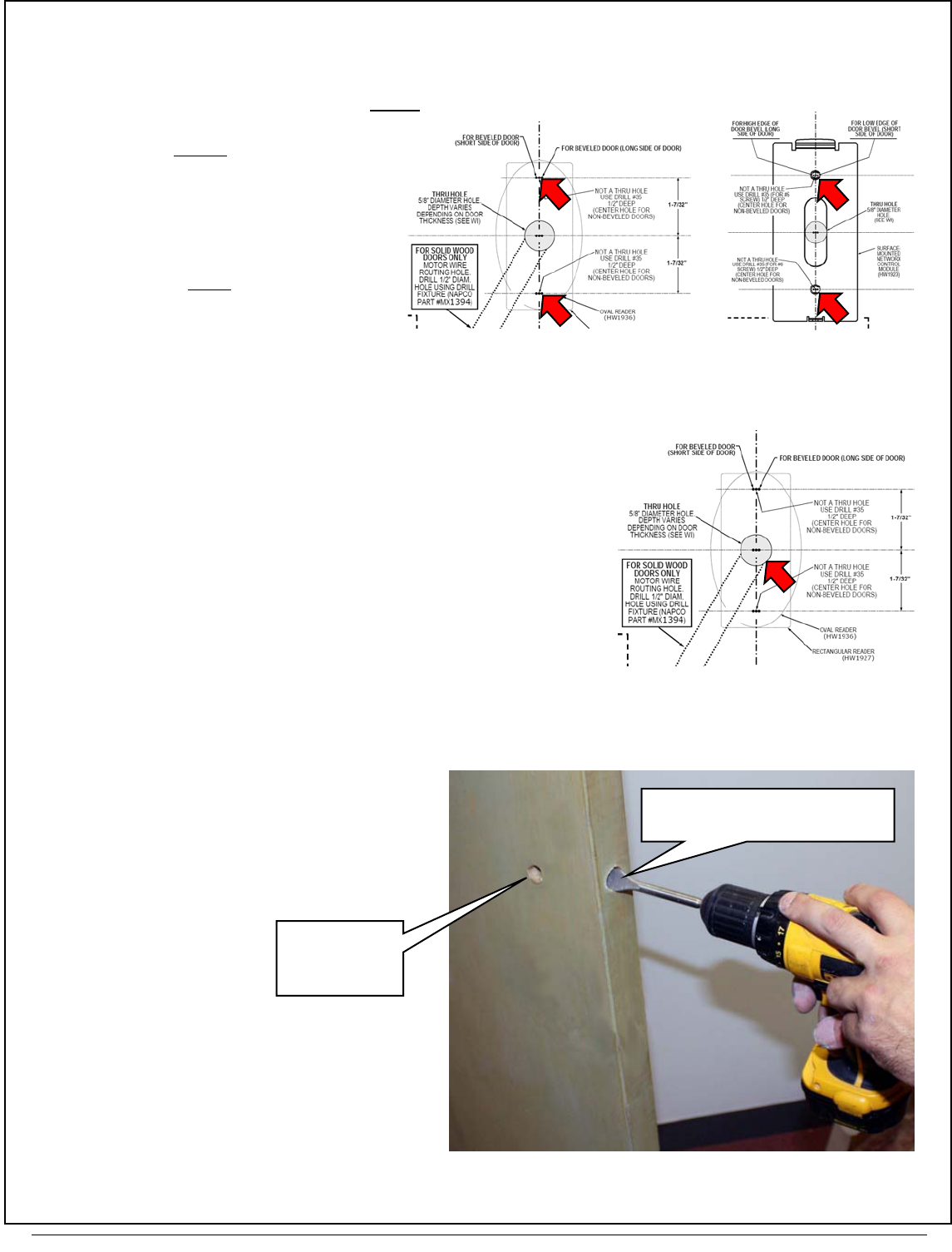
8. MARK TEMPLATE "SURFACE-MOUNTED NETWORX CONTROL UNIT" HOLES
On the inside ("protected") door surface, mark the two Control Unit Mounting Plate (Fig. 8) holes using the correct mark-
ings printed on the template (if door is beveled, use correct markings for beveled doors as described in step 1).
The center of the 5/8" Diameter Thru-Hole was already marked on the outside surface in step 4; for the inside door
surface, mark the center of this same 5/8" Diameter Thru-Hole. This 5/8" Diameter Thru-Hole is used for the Mortise
Lock Motor Wire, Proximity Reader and Door Contact Sensor wires.
Carefully remove the template.
FIG. 8: MARK THE TWO "CONTROL UNIT
MOUNTING PLATE" HOLES (ARROWS)
FIG. 7: EXAMPLE OF INSIDE
DOOR EDGE (ARROW)
ArchiTech Mortise Lock & Surface-Mounted Networx Control Unit Mounting and Installation Instructions
6
DOOR PREP: DRILL HOLES
IMPORTANT: Remove all burrs from wire holes. Sharp edges can eventually wear away wire insulation.
9. DRILL THE FOLLOWING HOLES IN THE DOOR
9A. Use 7/64" drill bit:
On the outside ("unprotected side")
door surface, drill the two pilot
holes for the Proximity Reader
mounting screws (NOT thru-holes,
drill only into the door surface).
9B. Use 7/64" drill bit:
On the inside ("protected side")
door surface, drill the two pilot
holes for the Control Unit Mounting
Plate mounting screws (NOT
thru-holes). Drill only into the in-
side door surface.
9C. Use 5/8" drill bit: 5/8" Diameter Thru-Hole.
Drill straight through the door.
9D. Use 3/4" drill bit: 3/4" Door Contact
Sensor hole in edge of the door
(for solid wood doors, drill until the
hole intersects with the 5/8" Diameter
Thru-Hole).
FIG. 9B: 7/64" PILOT HOLE
ON INSIDE DOOR SURFACE
FOR CONTROL UNIT PLATE
FIG. 9A: 7/64" PILOT HOLE ON OUT-
SIDE DOOR SURFACE FOR
PROXIMITY READER
FIG. 9C: 5/8" DIAMETER THRU-HOLE
(5/8" DIAMETER
THRU-HOLE,
DRILLED IN
STEP 9C)
"DOOR CONTACT SENSOR" HOLE
(3/4") IN EDGE OF DOOR
FIG. 9D: 3/4" DOOR CONTACT SENSOR HOLE IN EDGE OF THE DOOR
7
ArchiTech Mortise Lock & Surface-Mounted Networx Control Unit Mounting and Installation Instructions
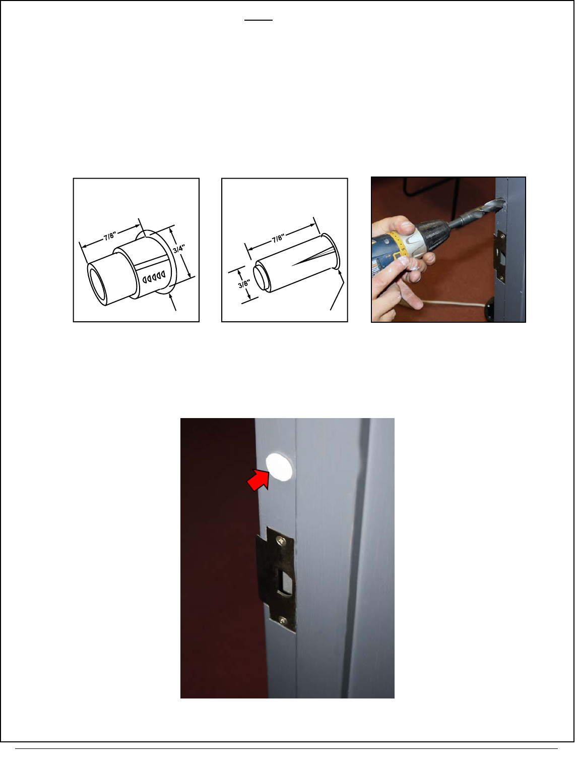
10. DRILL "DOOR CONTACT MAGNET" HOLE IN JAMB
10A. Find the Door Contact Magnet. The type provided will be either Type A (3/4" dia.) or Type B (3/8" dia.) as shown
in one of the two images in Fig. 10A below.
10B. Drill into the door jamb as follows:
For Hardwood Jambs:
For the thicker "Type A" contact (below left image): Drill a 3/4" hole 7/8" deep into the jamb (marked in
step 6).
For the thinner "Type B" contact (below right image): Drill a 3/8" hole 7/8" deep into the jamb (marked
in step 6).
For Hollow Metal Jambs:
Use either a 3/4" or 3/8" bit (depending on Door Contact Magnet Type A or Type B) to drill a hole into the sur-
face of the jamb.
10C. Insert the magnetic Door Contact Magnet in the jamb hole; the contact sits almost flush with the jamb when fully
inserted. In some cases, an adhesive may be needed to ensure a secure fit.
FIG. 10A: FIND THE "DOOR CONTACT MAGNET" PROVIDED, EITHER
TYPE A (3/4" DIAMETER) OR TYPE B (3/8" DIAMETER)
Φ 31/32" Φ 7/16"
Type A (3/4" dia.) Type B (3/8" dia.)
FIG. 10B: DRILL DOOR JAMB HOLE
(EITHER 3/8" OR 3/4" DEPENDING
ON TYPE)
FIG. 10C: DOOR CONTACT MAGNET
INSTALLED IN DOOR JAMB
ArchiTech Mortise Lock & Surface-Mounted Networx Control Unit Mounting and Installation Instructions
8
DECISION: HOW TO ROUTE THE MORTISE LOCK MOTOR WIRE?
The Mortise Lock body includes a Mortise Lock Motor Wire plug that must be routed to
and plugged into the Surface-Mounted Networx Control Unit that is mounted on
the inside ("protected side") of the door. HOW this Motor Wire is routed depends on
whether the door is solid or hollow:
Hollow Metal Doors:
Simply route the Mortise Lock Motor Wire within the hollow metal door. Skip to
step 12.
Solid Wood Doors:
Use the Mortise Drill Jig (part #N95I1DJ) to drill a pathway for the wire within the
solid wood door (from the Mortise Lock body to the 5/8" Diameter Thru-Hole).
Skip to step 11, below.
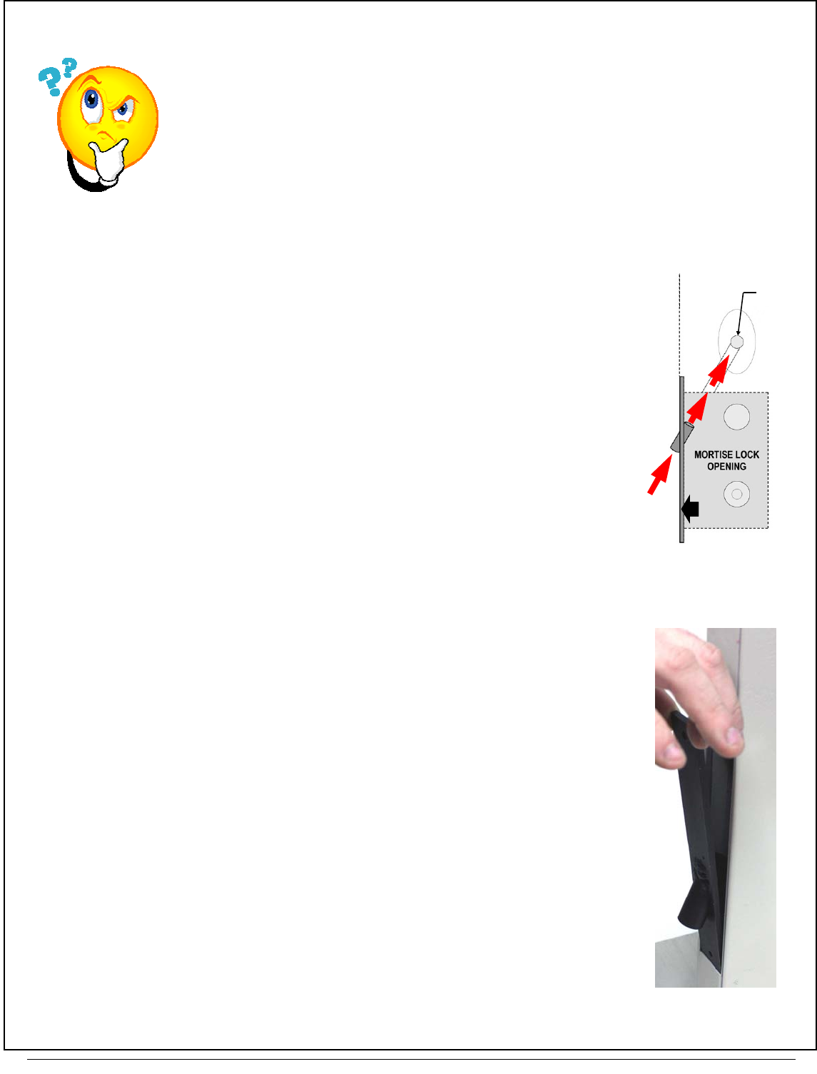
11. USING THE MORTISE DRILL JIG
The Mortise Drill Jig (part #N95I1DJ) MUST be used with solid wood doors. For
hollow metal doors, skip to step 12.
PURPOSE OF THE MORTISE DRILL JIG
The Mortise Drill Jig is used to drill a diagonal 1/2" hole through solid wood doors to
provide path for the Mortise Lock Motor Wire to run within the door and to be
plugged into the back of the Surface-Mounted Networx Control Unit.
In the steps that follow, the Jig will be secured to the edge of the door (in the
same location as the mortise lock faceplate). The hole will be drilled within the door,
as shown in profile on the template WI2102 and also in the Fig. 11 "side view" show-
ing where this Mortise Drill Jig is positioned and the path of this drilled interior hole.
11A. FASTEN DRILL JIG TO DOOR
The Mortise Drill Jig (part #N95I1DJ) is placed into the edge of the door, into the
same mortised opening that will be used for the Mortise Lock. Proceed as follows:
Insert the Jig into the Mortise Lock opening as shown in Fig. 11A. Secure the Jig
with the screws provided to prevent the Jig from shifting when in use.
Insert supplied 1/2-inch diameter wood drill bit into the Mortise Drill Jig and drill the
hole until the 5/8" Diameter Thru-Hole is reached.
When finished, remove the Jig.
FIG. 11: SIDE VIEW:
DRILL JIG (N95I1DJ)
DRILL HOLE INSIDE DOOR
JIG
5/8" THRU
-HOLE
FIG. 11A: MORTISE
DRILL JIG PLACEMENT
9
ArchiTech Mortise Lock & Surface-Mounted Networx Control Unit Mounting and Installation Instructions
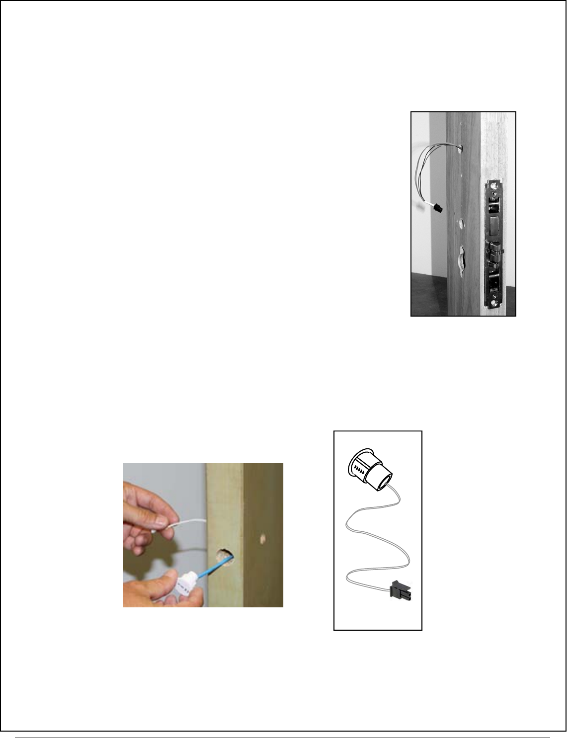
12. INSTALL THE "MORTISE LOCK BODY"
Insert the Mortise Lock Body into the door while feeding the Mortise Lock Motor Wire through to the 5/8" Diameter Thru
-Hole and then to the inside ("protected") side of the door.
Note: The Mortise Lock Motor Wire plug sleeve color is yellow.
Referencing the lock installation instructions, secure the Mortise Lock with the mounting hardware provided.
13. INSTALL "DOOR CONTACT SENSOR" IN DOOR EDGE
Insert the Door Contact Sensor wires into its 3/4" hole in the door edge and through to the 5/8" Diameter Thru-Hole
and then to the inside ("protected") side of the door.
Note: The Door Contact Sensor plug sleeve color is white.
FIG. 13: ROUTE TO THE INSIDE
("PROTECTED") SIDE OF THE DOOR FIG. 13A
DOOR CONTACT
SENSOR
FIG. 12: ROUTE MORTISE
LOCK WIRES THRU TO
THE PROTECTED SIDE
OF THE DOOR

ArchiTech Mortise Lock & Surface-Mounted Networx Control Unit Mounting and Installation Instructions
10
PROXIMITY READER INSTALLATION
Find the reader type provided, either rectangular or oval. If you have a Rectangular Proximity Reader, go to step 15. If
you have an Oval Proximity Reader, go to step 14 below.
14. OVAL PROXIMITY READER INSTALLATION
If you have a "Rectangular" Proximity Reader, go to step 15.
Note that the Oval Mounting Plate is symmetrical, and therefore has no "top" or "bottom".
14A. INSTALL THE "OVAL RUBBER GASKET" AND THE
"OVAL MOUNTING PLATE"
See Fig. 14A. Place the Oval Rubber Gasket against
the door surface, over the 5/8" Diameter Thru-Hole
that was drilled into the door in step 9C.
Place the Oval Mounting Plate on top of the Oval Rub-
ber Gasket, and secure (snug-tight only, do not over-
tighten) using the two Phillips Pan Head screws appro-
priate for the door type as follows:
For Metal Doors: #6-32
x 1/2" long Type F thread
cutting Phillips head (part
#SC212);
For Wood Doors: #6 x
1/2" long Type A Phillips
head (part #SC265)
Again, do NOT over-tighten these screws; over-
tightening will cause undesired deformation of the Rub-
ber Gasket.
FIG. C: OVAL PROXIMITY READER
(GO TO STEP 14 BELOW) FIG. D: RECTANGULAR PROXIMITY READER
(GO TO STEP 15)
Option 1 Option 2
DO NOT USE POWER DRILLS
OR POWER SCREWDRIVERS
WHEN INSTALLING THE
PROXIMITY READER !
FIG. 14A: "OVAL MOUNTING PLATE" (WITH LEFT AND
RIGHT "TABS") AND THE "OVAL RUBBER GASKET"
Oval Mounting Plate
Oval Rubber
Gasket
Left Tab
Right Tab
OVAL
Thru-Hole
11
ArchiTech Mortise Lock & Surface-Mounted Networx Control Unit Mounting and Installation Instructions
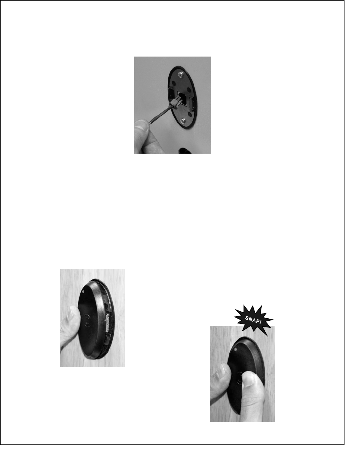
14B. RUN THE OVAL PROXIMITY READER WIRES
From the outside ("unprotected" side) of the door, feed the Proximity Reader wire fully into the 5/8" Diameter Thru-
Hole to the inside ("protected" side) of the door. Do not pinch wire.
Note: The Oval Proximity Reader plug sleeve color is orange.
14C. INSTALL OVAL PROXIMITY READER COVER
The Oval Proximity Reader cover "snaps" into place, as follows:
a. Hook the Reader on the Left Tab of the Mounting Plate.
b. Keep thumb pressure on left side.
c. Press firmly on the right side of the Reader until it
"snaps" into place.
Note: A spare Mounting Plate and Rubber Gasket
are provided if needed. Be careful not to pinch any
wires.
FIG. 14B: FEED THE WIRE
INTO THE 5/8" DIAMETER
THRU-HOLE (FROM
"OUTSIDE" TO "INSIDE")
FIG. 14C
FIG. 14CC
ArchiTech Mortise Lock & Surface-Mounted Networx Control Unit Mounting and Installation Instructions
12
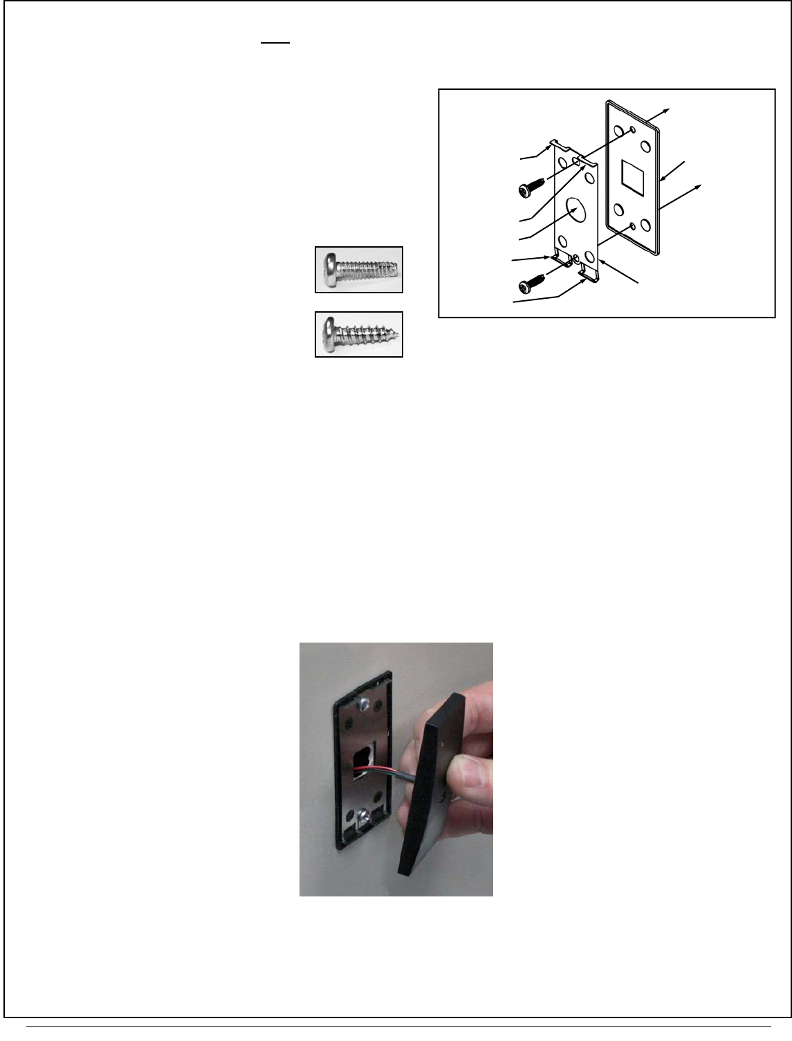
15. RECTANGULAR PROXIMITY READER INSTALLATION
The Rectangular Mounting Plate IS NOT symmetrical, and therefore does have a "top" and a "bottom". Note the two Top
Tabs and two Bottom Tabs shown in Fig. 15A:
15A. INSTALL THE "RECTANGULAR RUBBER GAS-
KET" AND THE "RECTANGULAR MOUNTING
PLATE"
See Fig. 15A. Place the Rectangular Rubber Gasket
over the 5/8" Diameter Thru-Hole that was drilled in-
to the door in step 9C, then place the Rectangular
Mounting Plate on top of the Rectangular Rubber
Gasket, and secure (snug-tight only, do not over-
tighten) using the two Phillips Pan Head screws appro-
priate for the door type as follows:
For Metal Doors: #6-32 x 1/2"
long Type F thread cutting Phil-
lips head (part #SC212);
For Wood Doors: #6 x 1/2"
long Type A Phillips head (part
#SC265)
Again, do NOT over-tighten these screws; over-
tightening will cause undesired deformation of the Rub-
ber Gasket.
15B. RUN THE RECTANGULAR PROXIMITY READER WIRES
From the outside ("unprotected" side) of the door, feed the Rectangular Proximity Reader wire fully into the 5/8"
Diameter Thru-Hole to the inside ("protected" side) of the door. Do not pinch wire.
Note: The Rectangular Proximity Reader plug sleeve color is orange.
FIG. 15A: "RECTANGULAR PROXIMITY READER
MOUNTING COMPONENTS
Rectangular Mounting Plate
Rectangular
Rubber Gasket
Bottom Tab
Bottom Tab
Top Tab
Top Tab
Thru-Hole
RECTANGULAR
FIG. 15B: FEED THE WIRE INTO
THE 5/8" DIAMETER THRU-HOLE
(FROM "OUTSIDE" TO "INSIDE")
13
ArchiTech Mortise Lock & Surface-Mounted Networx Control Unit Mounting and Installation Instructions
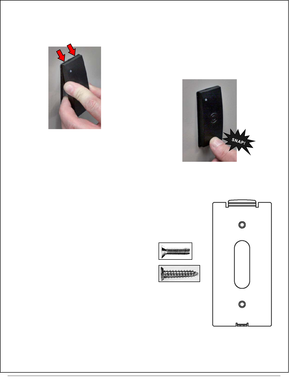
15C. INSTALL RECTANGULAR PROXIMITY READER COVER
The Rectangular Proximity Reader cover "snaps" into place, as follows:
a. Hook the Rectangular Proximity Reader on the two Top Tabs on the top of
the Rectangular Mounting Plate (see Fig 15C).
b. Press firmly on the bottom of the Rectangular Proximity
Reader until it "snaps" into place.
Be careful not to pinch any wires.
16. INSTALL "CONTROL UNIT MOUNTING PLATE"
Locate the two pilot holes for the Control Unit Mounting Plate mounting screws
that were drilled into the inside ("protected") door surface in step 9B.
Important! See Fig 16 to determine which end is the " TOP" .
Place the Control Unit Mounting Plate against the inside ("protected" side) door
surface and secure using the two Phillips Flat Head screws appropriate for the
door type as follows:
For Metal Doors: #6-32 x 5/8" long Type 23 thread
cutting Phillips Flat head, U-cut (part #SC682);
For Wood Doors: #6 x 3/4" long undercut self-
tapping Type A (part #SC596)
FIG. 15CC
FIG. 15C
FIG. 16:
CONTROL UNIT MOUNTING
PLATE
(TOP)
(BOTTOM)
ArchiTech Mortise Lock & Surface-Mounted Networx Control Unit Mounting and Installation Instructions
14
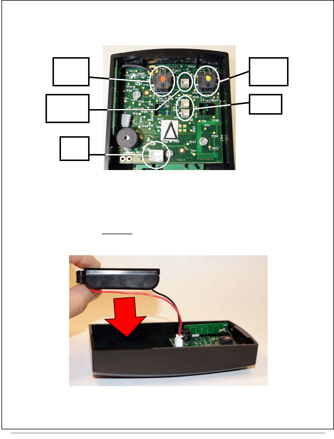
17. CONNECT PLUGS IN THE "SURFACE-MOUNTED NETWORX CONTROL UNIT"
Match the plug wire sleeve colors to the corresponding socket dot colors (see Fig. 17). Note: The rear of the Surface-
Mounted Networx Control Unit has five (5) sockets, but only three (3) are used.
18. CONNECT THE BATTERY PACK
See Fig. 18 for the location of the Battery Pack socket. Place the Battery Pack into the rear of the Surface-Mounted
Networx Control Unit with the flat side up, as shown in Fig. 18:
FIG. 17: CONTROL UNIT CONNECTIONS
J4
(YELLOW)
Lock Motor
Wire
(WHITE)
Door Contact
Sensor (J4)
DO NOT USE
(Reserved for
future use)
Battery
Pack
(ORANGE)
Proximity
Reader
FIG. 18: INSTALL BATTERY PACK WITH FLAT SIDE UP
15
ArchiTech Mortise Lock & Surface-Mounted Networx Control Unit Mounting and Installation Instructions
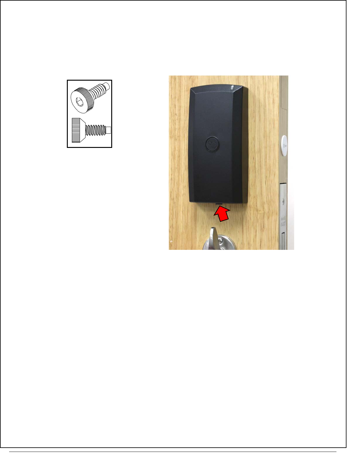
19. MOUNT THE "SURFACE-MOUNTED NETWORX CONTROL UNIT"
Before mounting, we recommend feeding all of the previously connected wires back into the door.
a. Hook the top of the Surface-Mounted Networx Control Unit into the top of the Control Unit Mounting Plate
and press the bottom until flush with the door surface.
b. Insert the "Dog Point" screw into the bottom of the Surface-Mounted Networx Control Unit (#6-32 Allen Head
countersunk U-cut Dog Point screw, part #SC681 as shown in Fig. 19). First thread this screw by hand using
the knurled head for grip, then tighten with the "rounded head" of the supplied Allen key.
FIG. 19: "DOG
POINT" SCREW
FIG. 19A: INSERT "DOG POINT" SCREW HERE

ArchiTech Mortise Lock & Surface-Mounted Networx Control Unit Mounting and Installation Instructions
16
NAPCO Security Technologies, Inc. (NAPCO) warrants its
products to be free from manufacturing defects in materi-
als and workmanship for twenty four months following the
date of manufacture. NAPCO will, within said period, at its
option, repair or replace any product failing to operate cor-
rectly without charge to the original purchaser or user.
This warranty shall not apply to any equipment, or any part
thereof, which has been repaired by others, improperly
installed, improperly used, abused, altered, damaged,
subjected to acts of God, or on which any serial numbers
have been altered, defaced or removed. Seller will not be
responsible for any dismantling or reinstallation charges,
environmental wear and tear, normal maintenance ex-
penses, or shipping and freight expenses required to re-
turn products to NAPCO. Additionally, this warranty shall
not cover scratches, abrasions or deterioration due to the
use of paints, solvents or other chemicals.
THERE ARE NO WARRANTIES, EXPRESS OR IM-
PLIED, WHICH EXTEND BEYOND THE DESCRIPTION
ON THE FACE HEREOF. THERE IS NO EXPRESS OR
IMPLIED WARRANTY OF MERCHANTABILITY OR A
WARRANTY OF FITNESS FOR A PARTICULAR PUR-
POSE. ADDITIONALLY, THIS WARRANTY IS IN LIEU
OF ALL OTHER OBLIGATIONS OR LIABILITIES ON THE
PART OF NAPCO.
Any action for breach of warranty, including but not limited
to any implied warranty of merchantability, must be
brought within the six months following the end of the war-
ranty period.
IN NO CASE SHALL NAPCO BE LIABLE TO ANYONE
FOR ANY CONSEQUENTIAL OR INCIDENTAL DAMAG-
ES FOR BREACH OF THIS OR ANY OTHER WARRAN-
TY, EXPRESS OR IMPLIED, EVEN IF THE LOSS OR
DAMAGE IS CAUSED BY THE SELLER'S OWN NEGLI-
GENCE OR FAULT.
In case of defect, contact the security professional who
installed and maintains your security system. In order to
exercise the warranty, the product must be returned by the
security professional, shipping costs prepaid and insured
to NAPCO. After repair or replacement, NAPCO assumes
the cost of returning products under warranty. NAPCO
shall have no obligation under this warranty, or otherwise,
if the product has been repaired by others, improperly in-
stalled, improperly used, abused, altered, damaged, sub-
jected to accident, nuisance, flood, fire or acts of God, or
on which any serial numbers have been altered, defaced
or removed. NAPCO will not be responsible for any dis-
mantling, reassembly or reinstallation charges, environ-
mental wear and tear, normal maintenance expenses, or
shipping and freight expenses required to return products
to NAPCO. Additionally, this warranty shall not cover
scratches, abrasions or deterioration due to the use of
paints, solvents or other chemicals.
This warranty contains the entire warranty. It is the sole
warranty and any prior agreements or representations,
whether oral or written, are either merged herein or are
expressly cancelled. NAPCO neither assumes, nor author-
izes any other person purporting to act on its behalf to
modify, to change, or to assume for it, any other warranty
or liability concerning its products.
In no event shall NAPCO be liable for an amount in ex-
cess of NAPCO's original selling price of the product, for
any loss or damage, whether direct, indirect, incidental,
consequential, or otherwise arising out of any failure of the
product. Seller's warranty, as hereinabove set forth, shall
not be enlarged, diminished or affected by and no obliga-
tion or liability shall arise or grow out of Seller's rendering
of technical advice or service in connection with Buyer's
order of the goods furnished hereunder.
NAPCO RECOMMENDS THAT THE ENTIRE SYSTEM
BE COMPLETELY TESTED WEEKLY.
Warning: Despite frequent testing, and due to, but not
limited to, any or all of the following; criminal tampering,
electrical or communications disruption, it is possible for
the system to fail to perform as expected. NAPCO does
not represent that the product/system may not be compro-
mised or circumvented; or that the product or system will
prevent any personal injury or property loss by burglary,
robbery, fire or otherwise; nor that the product or system
will in all cases provide adequate warning or protection. A
properly installed and maintained alarm may only reduce
risk of burglary, robbery, fire or otherwise but it is not in-
surance or a guarantee that these events will not occur.
CONSEQUENTLY, SELLER SHALL HAVE NO LIABILITY
FOR ANY PERSONAL INJURY, PROPERTY DAMAGE,
OR OTHER LOSS BASED ON A CLAIM THE PRODUCT
FAILED TO GIVE WARNING. Therefore, the installer
should in turn advise the consumer to take any and all
precautions for his or her safety including, but not limited
to, fleeing the premises and calling police or fire depart-
ment, in order to mitigate the possibilities of harm and/or
damage.
NAPCO is not an insurer of either the property or safety of
the user's family or employees, and limits its liability for
any loss or damage including incidental or consequential
damages to NAPCO's original selling price of the product
regardless of the cause of such loss or damage.
Some states do not allow limitations on how long an im-
plied warranty lasts or do not allow the exclusion or limita-
tion of incidental or consequential damages, or differenti-
ate in their treatment of limitations of liability for ordinary or
gross negligence, so the above limitations or exclusions
may not apply to you. This Warranty gives you specific
legal rights and you may also have other rights which vary
from state to state.
ArchiTech Networx Limited Warranty
