Alarm com orporated 143IS300 Image Sensor User Manual ISv3 Install Guide XT XTi Concord FCC 4 7 2017
Alarm.com Incorporated Image Sensor ISv3 Install Guide XT XTi Concord FCC 4 7 2017
UserManual.wiki
>
Alarm com orporated
>
143IS300 User Manual
Manual rev1.pdf
Navigation menu
Upload a User Manual
Namespaces
Wiki Guide
HTML
PDF
Info
Views
User Manual
Discussion / Help
Navigation
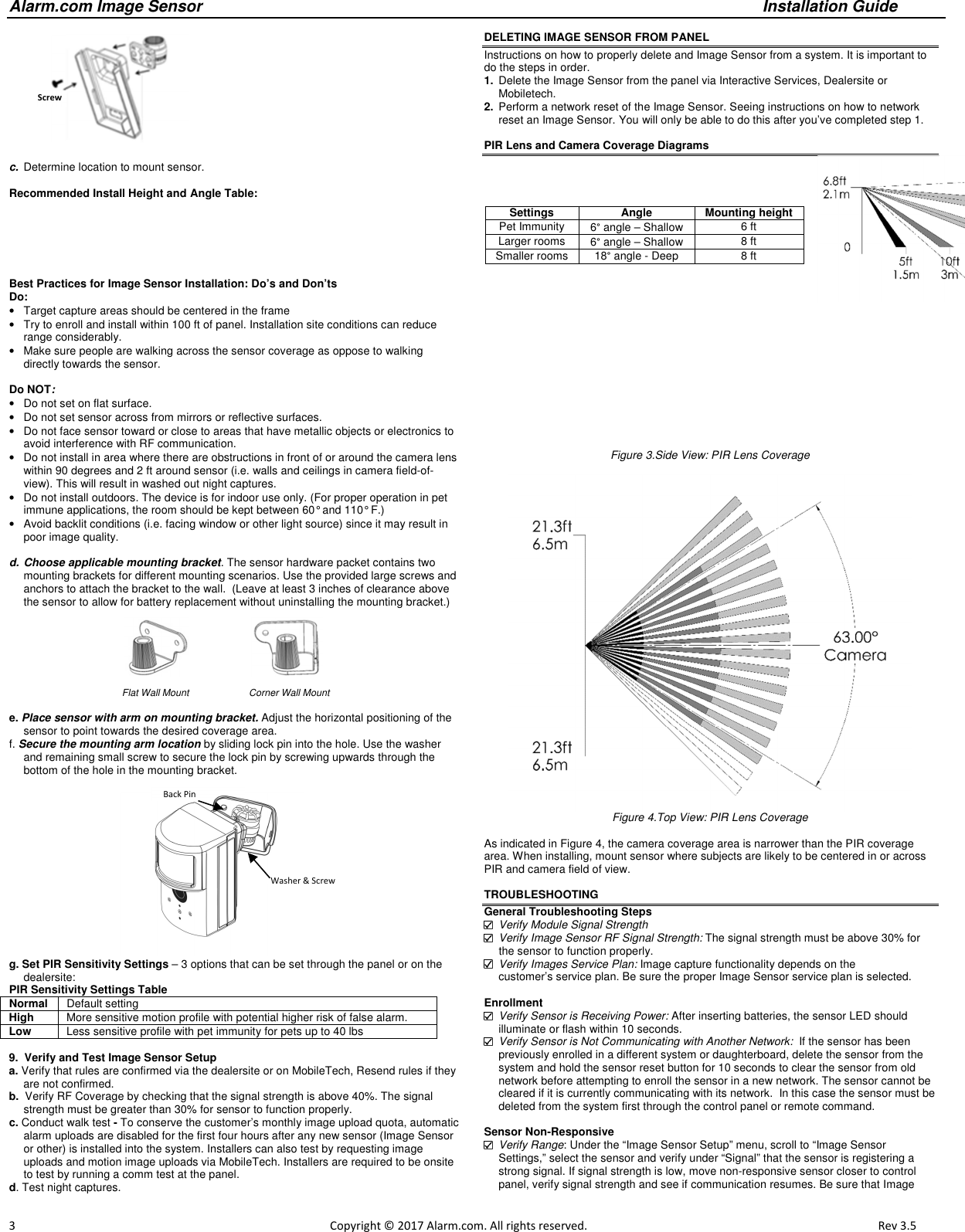
![Alarm.com Image Sensor Installation Guide 2 Copyright © 2017 Alarm.com. All rights reserved. Rev 3.5 RESETTING THE IMAGE SENSOR There are two ways to reset the Image Sensor: • Power Cycle – Power Cycle can be done by one of two ways: (1) Take out and reinsert batteries or (2) press and release the sensor reset button. Only press the reset button if no LED have been active in the last 10 seconds. After a power cycle the behavior of the Image Sensor will enter sensor power up state followed by the memory check state • Network reset - Press and hold a full 10 seconds or until the sensor red LED flashes rapidly to reset the sensor and clear it from its network. Release as soon as you see the rapid flashing. You must do a network reset prior to enrolling an Image Sensor in a new network. You must verify that the Image Sensor is first deleted from the panel it was previously learned into before you can do a network reset on the Image Sensor. See instructions on how to properly delete the Image Sensor from the panel. A network reset will only work if the Image Sensor is not actively communicating with a network. After releasing the reset button, the Image Sensor will enter sensor power-up mode (blinking red LED) followed by memory check (solid red LED) followed by either a blinking green or blinking yellow light. Blinking green means still enrolled in active network. Blinking yellows means the Image Sensor is no longer enrolled in a network and is actively looking for a panel in learn mode. See Camera LED Reference Chart for full list of status indicators and expected behavior after successful network reset has occurred. Figure 2. Sensor Reset Button PIR ACTIVATION & TEST MODE By default, the image sensor LED does not illuminate when activated by motion unless the sensor is in test mode. The LED can be enabled by tampering the device, via the Alarm.com Dealer Website, or on the panel for each Image Sensor on a customer’s account. The Image Sensor must have successfully completed the enrollment process with a panel. When enabled, the red LED illuminates for 3 seconds upon motion activations (at most every 3 minutes while disarmed). Instructions to activate on the panel (Note: It may take up to 30 seconds for test mode to take effect after requesting “Test PIR” at the panel): • On the XT panel, go to “Image Sensor Setup” menu and scroll to “Image Sensor Settings”. Enter “Image Sensor Settings” and scroll to the sensor to test, press “OK.” Scroll to “Image Sensor [y] Test PIR,” and press OK to put the device in test mode. • On the XTi panel, enter the “Test” menu under “Image Sensor” and press “PIR”. The screen will display a confirmation to indicate the test mode command has been sent. • Test mode cannot be activated from the Concord panel. TAMPER & TROUBLE CONDITIONS Tamper: A built-in accelerometer detects movement or re-positioning of the Image Sensor and will initiate a tamper whenever a change in sensor orientation is detected. The tamper automatically clears after the sensor is returned to the upright position and no movement has been detected for 5 minutes. A tamper can also be cleared by resetting the sensor. Trouble Conditions: By default, trouble conditions (malfunction, tamper & low battery) are displayed on the panel LCD. Enable or disable trouble condition messages on the control panel LCD via the Alarm.com Dealer Website. Trouble conditions are always reported to the Alarm.com Customer Website and customers will receive tamper/low/malfunction notifications if they are subscribed, regardless of the panel setting. SERVICE PLANS REQUIREMENTS Image capture features require a service plan that includes one of the following Image Sensor add-ons: • Images - Alarms- Includes upload of images from alarm events only. • Images - Plus- Includes upload of images from alarm events and non-alarm events HARDWARE INSTALLATION 1. Create Alarm.com Customer Account - Select service plan (see Service Plan Requirements) and register the Alarm.com module serial number on the Alarm.com Dealer Website. 2. Install Image Sensor Daughterboard if necessary. – First check Hardware Compatibility to verify if module needs a daughterboard. If it does, see Daughterboard Install Guide for daughterboard installation instructions. Install Alarm.com Module inside Control Panel 4. Register Module and Test - Power up the panel and initiate a comm-test to ensure the Alarm.com module is properly installed and communicating with the Alarm.com NOC. 5. Enroll Sensor in Panel – Instructions specific by pane Simon XT a. Begin with the batteries removed from the sensor. b. On panel go to “System Programming” > Enter installer code (default 4-3-2-1) > Select “Interactive Services” > Select “Image Sensor Setup” > Select “Image Sensor Learn Mode” > Screen should display “Power up or set I. S. Mode”. c. Insert the batteries into the sensor. Wait (approximately 20 seconds) for the control panel screen to display: “I.S. [x] Added as Sensor [y].” The LED should follow the following sequence: blinking red > blinking yellow > solid yellow > alternating yellow and green > solid green. You may see a red blink after the solid green which means the sensor is in PIR test mode. See the Camera LED Reference Chart for more details. c. Perform another panel comm-test to be sure that Alarm.com receives the updated device equipment list. This will speed up the sensor initialization process. The sensor is now learned into the panel. Sensors are enrolled in group 17 by default. To change the sensor group, use the Sensors menu in System Programming. Image Sensors may be enrolled in groups 15, 17, 20, or 25. (No chime issued for group 25.) On the Simon XT a mix of sensor groups 15/17 and 20 are not supported. If Image Sensors are in group 15 or 17, they cannot also be in group 20, and vice versa. After enrollment, be sure to keep the sensor and panel powered so the sensor can complete an initialization process with the Alarm.com Network Operations Center. This process will take several minutes. Images cannot be captured until initialization is complete. Check by verifying if the rules are confirmed on the dealersite or MobileTech. Simon XTi a. Begin with the batteries removed from the sensor. b. On the panel, scroll until the screen shows “Programming” > Enter installer code (default 4-3-2-1) > Select “Interactive Services” > Select “Image Sensor” > Select “Add” > The screen will display “Reset or power-up sensor to enroll…” c. Insert the batteries into the sensor. Wait (approximately 20 seconds) for the control panel screen to display: “IS[x] successfully added as sensor [y].” The LED should follow the following sequence: blinking red > blinking yellow > solid yellow > alternating yellow and green > solid green. You may see a red blink after the solid green which means the sensor is in PIR test mode. See the Camera LED Reference Chart for more details. d. Perform another panel comm-test to be sure that Alarm.com receives the updated device. equipment list. This will speed up the sensor initialization process. The sensor is now learned into the panel. Sensors are enrolled in group 17 by default. To change the sensor group, use the Sensors menu in Programming. Image Sensors may be enrolled in groups 15, 17, 20, or 25. (No chime issued for group 25.) After enrollment, be sure to keep the sensor and panel powered so the sensor can complete an initialization process with the Alarm.com Network Operations Center. This process will take several minutes. Images cannot be captured until initialization is complete. Check by verifying if the rules are confirmed on the dealersite or MobileTech. Concord a. Install Image Sensor Daughterboard – See Daughterboard Install Guide for more details. b. Connect Daughterboard Alarm Wire – See Daughterboard Install Guide for more details. c. Register Module and Test - Power up the panel and initiate a comm-test to ensure the Alarm.com module is properly installed and communicating with the Alarm.com NOC. d. To begin enrolling Image Sensor on panel - Begin with the batteries removed from the sensor and ensure the panel is not in System Programming. e. Press button on IS daughterboard to enter ‘Add Mode.’ The green LED “Z2” will start a 4-blink pattern indicating that the daughterboard is in ‘Add Mode’. f. Reset or insert the batteries into the image sensor. “Z2” LED on the daughterboard will be solid for 60 seconds to indicate that the sensor has been added. On the Image Sensor, The LED should follow the following sequence: blinking red > blinking yellow > solid yellow > alternating yellow and green > solid green. You may see a red blink after the solid green which means the sensor is in PIR test mode. See the Camera LED Reference Chart for more details. Note: The Image Sensor WILL NOT show in the panel’s sensors menu as occupying a panel zone, but the zone must be reserved for the Image Sensor. It is enrolled starting with zone 92 and counts down. The Alarm.com Dealer Site equipment list will show the Image Senor in its enrolled zone. By default, the sensors are enrolled in partition 1 and group 17. During step 6, the Image Sensors will be re-assigned to follow the partition and group of the hardwire. g. To begin enrolling Image Sensor Alarm Hardwire in panel - Enter sensor enrollment menu in System Programming. h. Select the partition number, zone number, and sensor group for the hardwire. i. Trip daughterboard hardwire by pressing button on top of daughterboard. The red LED “Z1” on daughterboard will turn off when pressed. j. Exit system programming. The Image Sensors will now be assigned to the group and partition of the hardwire. k. Perform another panel comm-test to be sure that Alarm.com receives the updated device equipment list. This will speed up the sensor initialization process. Image Sensors may be enrolled in groups 15, 17, 20, or 25. The Image Sensors must follow the partition and group of the alarm hardwire and cannot be individually configured. After enrollment, be sure to keep the sensor and panel powered so the sensor can complete an initialization process with the Alarm.com Network Operations Center. This process will take several minutes. Images cannot be captured until initialization is complete. Check by verifying if the rules are confirmed on the dealersite or MobileTech. 6. Mount Sensor a. Determine the desired mounting angle – 3 options Option 1: 12° angle – Straight on the wall without bracket Option 2: 6° angle – Shallow o Teeth up orientation o 35 ft coverage o Pet immunity Option 3: 18° angle - Deep o Teeth down orientation o Recommended for smaller rooms b. Screw bracket to back plate. Insert Paperclip to access reset button](https://usermanual.wiki/Alarm-com-orporated/143IS300/User-Guide-3350873-Page-2.png)