Alarm com orporated 143IS300 Image Sensor User Manual ISv3 Install Guide XT XTi Concord FCC 4 7 2017
Alarm.com Incorporated Image Sensor ISv3 Install Guide XT XTi Concord FCC 4 7 2017
Manual rev1.pdf
Interlogix part number:
Alarm.com part number: ADC-IS-300-LP
Alarm.com Image Sensor Version 3 - Interlogix Installation Guide
1 Copyright © 2017 Alarm.com. All rights reserved. Rev 3.5
PRODUCT SUMMARY & TECHNICAL SPECIFICATIONS
The Image Sensor is a pet immune PIR (passive infrared) motion detector with a built-in
camera designed to capture images during alarm or non-alarm events when motion is
detected.
Product Features:
• Communicates wirelessly to the security control panel
• 35 foot detection range with a 90 degree horizontal FOV-ALR
• Configurable PIR sensitivity and pet immunity settings
• Image: VGA 640x480 pixels
• Color Images (except in night vision)
• Night vision image capture with infrared flash (black & white)
• Tamper detection, walk test mode, supervision
• All systems can support up to three Image Sensors
• UL 639 certified
Technical Specifications:
• Alarm.com Model Number: ADC-IS-300-LP
• Interlogix Part Numbers:
• Power Source: Recommended 2 AA 1.5v Energizer Ultimate Lithium Batteries.
• Batteries: Refer to the Batteries section for details
• Operating Temperature Range: 32° to 110°F for non-pet applications, 60° to 110°F for
pet applications.
• Weight: 3.1 oz. (with batteries and without mounting accessories)
• Dimensions: 3.1’’ h x 1.8’’ w x 2.3’’ d
• Supervisory Interval: 100 minutes (sensor), 3 hours (alarm hardwire)
• Wireless Signal Range: Greater than 400 ft open air
• Color: White
• Recommended Mounting Height and Angle: Refer to the Recommended Install
Height and Angle Table
• Motion Profiles & Sensor Range: Refer to the PIR Sensitivity Settings Table
HARDWARE COMPATIBILITY REQUIREMENTS – By Panel
Panel Panel
Version Module
Firmware Extra Hardware Other
Simon
XT V1.3+ Firmware 146+ Requires Image
Sensor
Daughterboard for
modules with
firmware 185 or
lower. Compatible
with all
daughterboard
versions.
Daughterboard
will take one
zone
Simon
XTi V1.0+ Firmware 151+ No
Concord 4.0+ CDMA – v177+
HSPA – v183+
Requires
daughterboard with
v104.0+
All Image
Sensors must be
enrolled in same
partition.
OTHER FEATURE COMPATIBILITY
Two-Way Voice Compatibility - Images cannot be transmitted while a Two-Way Voice
call is in session. When the Image Sensor is installed on a system with Two-Way Voice
over the cellular network, image transmission during an alarm may be interrupted by the
two-way session. The image transmission resumes once the call has terminated.
Simon XT 2WTTS Compatibility - When using a Two Way Talking Touchscreen with the
Simon XT panel, Image Sensor activity during alarms is reported or visible on the
touchscreen. When alarms are tripped on an enrolled Image Sensor, the alarms are
reported and displayed on the 2WTTS through the sensor 39 hardwire zone. Periodic
activations on hardwire zone 39 will appear on the touchscreen as a result of the hardwire
supervisions.
PET IMMUNITY SETTINGS
Two parts to making the Image Sensor pet immune:
1. Set PIR sensitivity settings to “low”,
2. Mount set at a height of 6 ft, and install the sensor with the 6 degree mounting angle.
BATTERIES
Battery type: The Image Sensor uses 2 AA 1.5v Energizer Ultimate Lithium batteries (UL
compliant).
Expected Battery Life: Approximately 4 years with lithium batteries.
Voltage Thresholds: With lithium batteries, low battery alerts are issued at 3.05V. The
sensor cannot operate when the voltage reads below 2.30V.
Low Battery Notification: Panel will display a low battery alert for the sensor and/or
notifications are issued via the Alarm.com platform if the customer has subscribed to this
notification type.
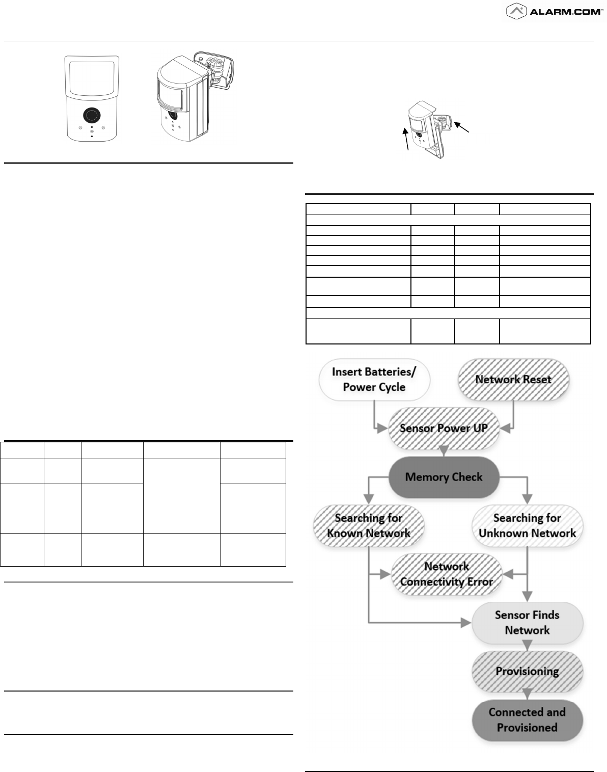
Replacing batteries: To replace the sensor batteries, slide the front of the sensor up off
the sensor-back. Dispose of used batteries per the battery manufacturer instructions and
following local regulations.
Figure 1. Removing Sensor for Battery Replacement
CAMERA LED REFERENCE CHART
Camera LED Chart: Refer to this chart to understand the camera LED patterns.
Device Status or Error LED Pattern Duration of LED Pattern
Device & Network State
Sensor Power Up Red Blinking 3 seconds
Memory Check Red Solid 10 seconds
Searching for Unknown Network
Yellow Blinking 2 minutes
Searching for Known Network Green Blinking 2 minutes
Sensor Finds Network Yellow Solid 5 seconds
Provisioning Yellow &
Green Alternating
blinks 5-minute timeout
Connected and Provisioned Green Solid 5 seconds
Device Reset
Network Reset Red Blinking
(fast)
Hold the reset button for
ten seconds OR until the
LED flashes rapidly.
Hold Here
Slide Up
Alarm.com Image Sensor Installation Guide
2 Copyright © 2017 Alarm.com. All rights reserved. Rev 3.5
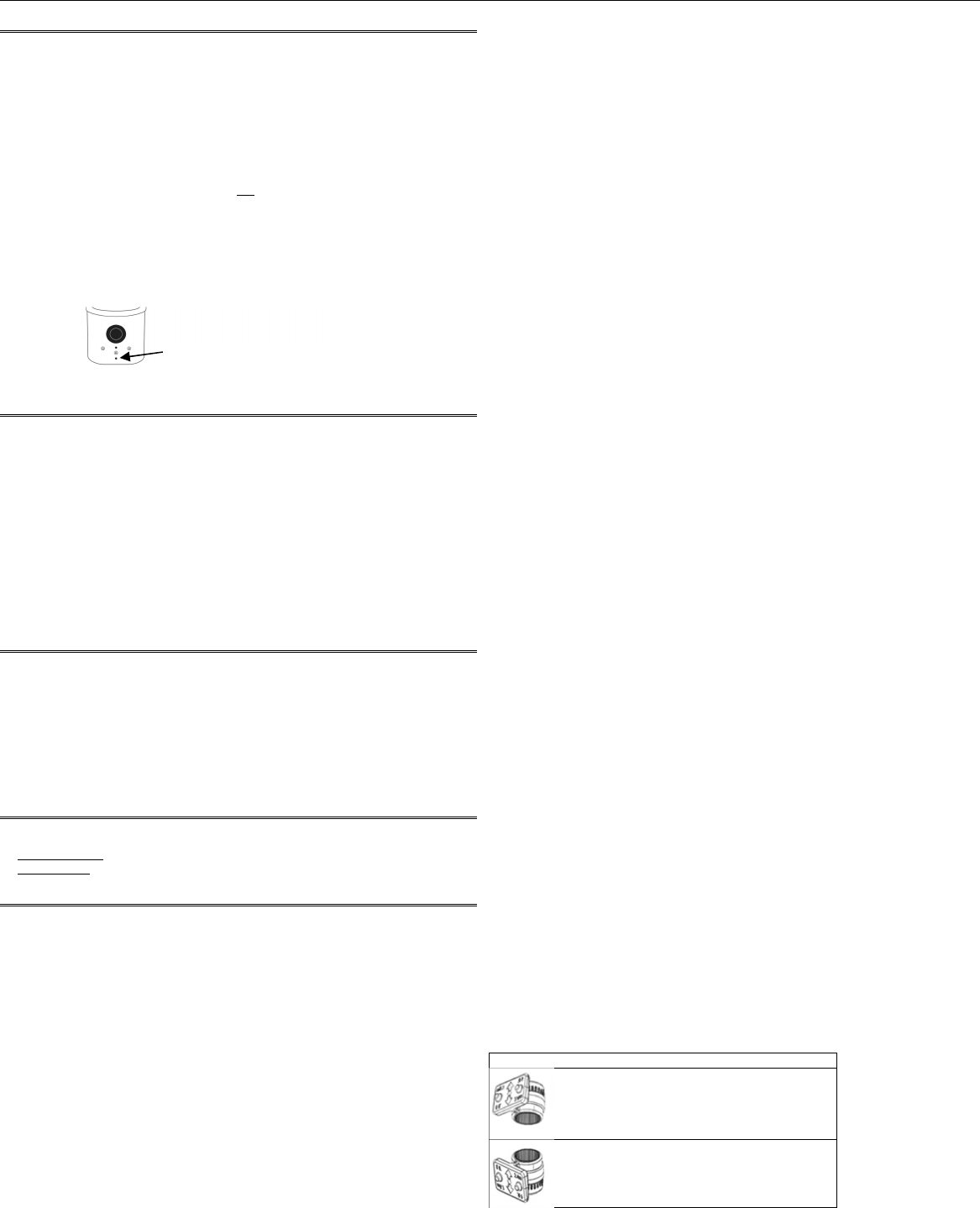
RESETTING THE IMAGE SENSOR
There are two ways to reset the Image Sensor:
• Power Cycle – Power Cycle can be done by one of two ways: (1) Take out and reinsert
batteries or (2) press and release the sensor reset button. Only press the reset button if
no LED have been active in the last 10 seconds. After a power cycle the behavior of the
Image Sensor will enter sensor power up state followed by the memory check state
• Network reset - Press and hold a full 10 seconds or until the sensor red LED flashes
rapidly to reset the sensor and clear it from its network. Release as soon as you see the
rapid flashing. You must do a network reset prior to enrolling an Image Sensor in a new
network. You must verify that the Image Sensor is first deleted from the panel it was
previously learned into before you can do a network reset on the Image Sensor. See
instructions on how to properly delete the Image Sensor from the panel. A network
reset will only work if the Image Sensor is not actively communicating with a network.
After releasing the reset button, the Image Sensor will enter sensor power-up mode
(blinking red LED) followed by memory check (solid red LED) followed by either a
blinking green or blinking yellow light. Blinking green means still enrolled in active
network. Blinking yellows means the Image Sensor is no longer enrolled in a network
and is actively looking for a panel in learn mode. See Camera LED Reference Chart for
full list of status indicators and expected behavior after successful network reset has
occurred.
Figure 2. Sensor Reset Button
PIR ACTIVATION & TEST MODE
By default, the image sensor LED does not illuminate when activated by motion unless the
sensor is in test mode. The LED can be enabled by tampering the device, via the
Alarm.com Dealer Website, or on the panel for each Image Sensor on a customer’s
account. The Image Sensor must have successfully completed the enrollment process
with a panel. When enabled, the red LED illuminates for 3 seconds upon motion
activations (at most every 3 minutes while disarmed).
Instructions to activate on the panel (Note: It may take up to 30 seconds for test mode to
take effect after requesting “Test PIR” at the panel):
• On the XT panel, go to “Image Sensor Setup” menu and scroll to “Image Sensor
Settings”. Enter “Image Sensor Settings” and scroll to the sensor to test, press “OK.”
Scroll to “Image Sensor [y] Test PIR,” and press OK to put the device in test mode.
• On the XTi panel, enter the “Test” menu under “Image Sensor” and press “PIR”. The
screen will display a confirmation to indicate the test mode command has been sent.
• Test mode cannot be activated from the Concord panel.
TAMPER & TROUBLE CONDITIONS
Tamper: A built-in accelerometer detects movement or re-positioning of the Image Sensor
and will initiate a tamper whenever a change in sensor orientation is detected. The tamper
automatically clears after the sensor is returned to the upright position and no movement
has been detected for 5 minutes. A tamper can also be cleared by resetting the sensor.
Trouble Conditions: By default, trouble conditions (malfunction, tamper & low battery)
are displayed on the panel LCD. Enable or disable trouble condition messages on the
control panel LCD via the Alarm.com Dealer Website. Trouble conditions are always
reported to the Alarm.com Customer Website and customers will receive
tamper/low/malfunction notifications if they are subscribed, regardless of the panel setting.
SERVICE PLANS REQUIREMENTS
Image capture features require a service plan that includes one of the following Image
Sensor add-ons:
• Images - Alarms- Includes upload of images from alarm events only.
• Images - Plus- Includes upload of images from alarm events and non-alarm events
HARDWARE INSTALLATION
1. Create Alarm.com Customer Account - Select service plan (see Service Plan
Requirements) and register the Alarm.com module serial number on the Alarm.com
Dealer Website.
2. Install Image Sensor Daughterboard if necessary. – First check Hardware
Compatibility to verify if module needs a daughterboard. If it does, see Daughterboard
Install Guide for daughterboard installation instructions.
Install Alarm.com Module inside Control Panel
4. Register Module and Test - Power up the panel and initiate a comm-test to ensure the
Alarm.com module is properly installed and communicating with the Alarm.com NOC.
5. Enroll Sensor in Panel – Instructions specific by pane
Simon XT
a. Begin with the batteries removed from the sensor.
b. On panel go to “System Programming” > Enter installer code (default 4-3-2-1) > Select
“Interactive Services” > Select “Image Sensor Setup” > Select “Image Sensor Learn
Mode” > Screen should display “Power up or set I. S. Mode”.
c. Insert the batteries into the sensor. Wait (approximately 20 seconds) for the control
panel screen to display: “I.S. [x] Added as Sensor [y].” The LED should follow the
following sequence: blinking red > blinking yellow > solid yellow > alternating yellow
and green > solid green. You may see a red blink after the solid green which means the
sensor is in PIR test mode. See the Camera LED Reference Chart for more details.
c. Perform another panel comm-test to be sure that Alarm.com receives the updated
device equipment list. This will speed up the sensor initialization process.
The sensor is now learned into the panel. Sensors are enrolled in group 17 by default. To
change the sensor group, use the Sensors menu in System Programming. Image Sensors
may be enrolled in groups 15, 17, 20, or 25. (No chime issued for group 25.) On the Simon
XT a mix of sensor groups 15/17 and 20 are not supported. If Image Sensors are in group
15 or 17, they cannot also be in group 20, and vice versa. After enrollment, be sure to
keep the sensor and panel powered so the sensor can complete an initialization process
with the Alarm.com Network Operations Center. This process will take several minutes.
Images cannot be captured until initialization is complete. Check by verifying if the rules
are confirmed on the dealersite or MobileTech.
Simon XTi
a. Begin with the batteries removed from the sensor.
b. On the panel, scroll until the screen shows “Programming” > Enter installer code
(default 4-3-2-1) > Select “Interactive Services” > Select “Image Sensor” > Select “Add”
> The screen will display “Reset or power-up sensor to enroll…”
c. Insert the batteries into the sensor. Wait (approximately 20 seconds) for the control
panel screen to display: “IS[x] successfully added as sensor [y].” The LED should follow
the following sequence: blinking red > blinking yellow > solid yellow > alternating yellow
and green > solid green. You may see a red blink after the solid green which means the
sensor is in PIR test mode. See the Camera LED Reference Chart for more details.
d. Perform another panel comm-test to be sure that Alarm.com receives the updated
device. equipment list. This will speed up the sensor initialization process.
The sensor is now learned into the panel. Sensors are enrolled in group 17 by default. To
change the sensor group, use the Sensors menu in Programming. Image Sensors may be
enrolled in groups 15, 17, 20, or 25. (No chime issued for group 25.) After enrollment, be
sure to keep the sensor and panel powered so the sensor can complete an initialization
process with the Alarm.com Network Operations Center. This process will take several
minutes. Images cannot be captured until initialization is complete. Check by verifying if
the rules are confirmed on the dealersite or MobileTech.
Concord
a. Install Image Sensor Daughterboard – See Daughterboard Install Guide for more
details.
b. Connect Daughterboard Alarm Wire – See Daughterboard Install Guide for more
details.
c. Register Module and Test - Power up the panel and initiate a comm-test to ensure the
Alarm.com module is properly installed and communicating with the Alarm.com NOC.
d. To begin enrolling Image Sensor on panel - Begin with the batteries removed from the
sensor and ensure the panel is not in System Programming.
e. Press button on IS daughterboard to enter ‘Add Mode.’ The green LED “Z2” will start a
4-blink pattern indicating that the daughterboard is in ‘Add Mode’.
f. Reset or insert the batteries into the image sensor. “Z2” LED on the daughterboard will
be solid for 60 seconds to indicate that the sensor has been added. On the Image
Sensor, The LED should follow the following sequence: blinking red > blinking yellow >
solid yellow > alternating yellow and green > solid green. You may see a red blink after
the solid green which means the sensor is in PIR test mode. See the Camera LED
Reference Chart for more details.
Note: The Image Sensor WILL NOT show in the panel’s sensors menu as occupying a
panel zone, but the zone must be reserved for the Image Sensor. It is enrolled starting with
zone 92 and counts down. The Alarm.com Dealer Site equipment list will show the Image
Senor in its enrolled zone. By default, the sensors are enrolled in partition 1 and group 17.
During step 6, the Image Sensors will be re-assigned to follow the partition and group of the
hardwire.
g. To begin enrolling Image Sensor Alarm Hardwire in panel - Enter sensor enrollment
menu in System Programming.
h. Select the partition number, zone number, and sensor group for the hardwire.
i. Trip daughterboard hardwire by pressing button on top of daughterboard. The red LED
“Z1” on daughterboard will turn off when pressed.
j. Exit system programming. The Image Sensors will now be assigned to the group and
partition of the hardwire.
k. Perform another panel comm-test to be sure that Alarm.com receives the updated
device equipment list. This will speed up the sensor initialization process.
Image Sensors may be enrolled in groups 15, 17, 20, or 25. The Image Sensors must
follow the partition and group of the alarm hardwire and cannot be individually configured.
After enrollment, be sure to keep the sensor and panel powered so the sensor can
complete an initialization process with the Alarm.com Network Operations Center. This
process will take several minutes. Images cannot be captured until initialization is
complete. Check by verifying if the rules are confirmed on the dealersite or MobileTech.
6. Mount Sensor
a. Determine the desired mounting angle – 3 options
Option 1: 12° angle – Straight on the wall without bracket
Option 2: 6° angle – Shallow
o Teeth up orientation
o 35 ft coverage
o Pet immunity
Option 3: 18° angle - Deep
o Teeth down orientation
o Recommended for smaller rooms
b. Screw bracket to back plate.
Insert Paperclip to access reset button
Alarm.com Image Sensor Installation Guide
3 Copyright © 2017 Alarm.com. All rights reserved. Rev 3.5
c. Determine location to mount sensor.
Recommended Install Height and Angle Table:
Best Practices for Image Sensor Installation: Do’s and Don’ts
Do:
• Target capture areas should be centered in the frame
• Try to enroll and install within 100 ft of panel. Installation site conditions can reduce
range considerably.
• Make sure people are walking across the sensor coverage as oppose to walking
directly towards the sensor.
Do NOT:
• Do not set on flat surface.
• Do not set sensor across from mirrors or reflective surfaces.
• Do not face sensor toward or close to areas that have metallic objects or electronics to
avoid interference with RF communication.
• Do not install in area where there are obstructions in front of or around the camera lens
within 90 degrees and 2 ft around sensor (i.e. walls and ceilings in camera field-of-
view). This will result in washed out night captures.
• Do not install outdoors. The device is for indoor use only. (For proper operation in pet
immune applications, the room should be kept between 60° and 110° F.)
• Avoid backlit conditions (i.e. facing window or other light source) since it may result in
poor image quality.
d. Choose applicable mounting bracket. The sensor hardware packet contains two
mounting brackets for different mounting scenarios. Use the provided large screws and
anchors to attach the bracket to the wall. (Leave at least 3 inches of clearance above
the sensor to allow for battery replacement without uninstalling the mounting bracket.)
Flat Wall Mount Corner Wall Mount
e. Place sensor with arm on mounting bracket. Adjust the horizontal positioning of the
sensor to point towards the desired coverage area.
f. Secure the mounting arm location by sliding lock pin into the hole. Use the washer
and remaining small screw to secure the lock pin by screwing upwards through the
bottom of the hole in the mounting bracket.
g. Set PIR Sensitivity Settings – 3 options that can be set through the panel or on the
dealersite:
PIR Sensitivity Settings Table
Normal Default setting
High More sensitive motion profile with potential higher risk of false alarm.
Low Less sensitive profile with pet immunity for pets up to 40 lbs
9. Verify and Test Image Sensor Setup
a. Verify that rules are confirmed via the dealersite or on MobileTech, Resend rules if they
are not confirmed.
b. Verify RF Coverage by checking that the signal strength is above 40%. The signal
strength must be greater than 30% for sensor to function properly.
c. Conduct walk test - To conserve the customer’s monthly image upload quota, automatic
alarm uploads are disabled for the first four hours after any new sensor (Image Sensor
or other) is installed into the system. Installers can also test by requesting image
uploads and motion image uploads via MobileTech. Installers are required to be onsite
to test by running a comm test at the panel.
d. Test night captures.
DELETING IMAGE SENSOR FROM PANEL
Instructions on how to properly delete and Image Sensor from a system. It is important to
do the steps in order.
1. Delete the Image Sensor from the panel via Interactive Services, Dealersite or
Mobiletech.
2. Perform a network reset of the Image Sensor. Seeing instructions on how to network
reset an Image Sensor. You will only be able to do this after you’ve completed step 1.
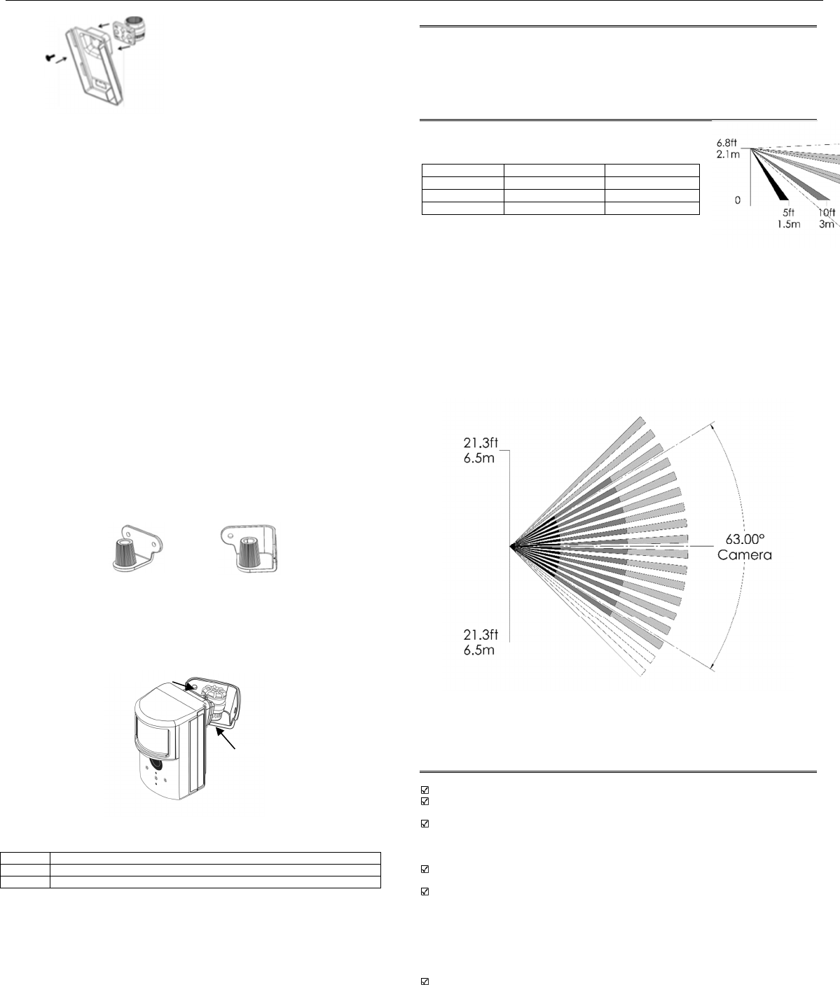
PIR Lens and Camera Coverage Diagrams
Figure 3.Side View: PIR Lens Coverage
Figure 4.Top View: PIR Lens Coverage
As indicated in Figure 4, the camera coverage area is narrower than the PIR coverage
area. When installing, mount sensor where subjects are likely to be centered in or across
PIR and camera field of view.
TROUBLESHOOTING
General Troubleshooting Steps
Verify Module Signal Strength
Verify Image Sensor RF Signal Strength: The signal strength must be above 30% for
the sensor to function properly.
Verify Images Service Plan: Image capture functionality depends on the
customer’s service plan. Be sure the proper Image Sensor service plan is selected.
Enrollment
Verify Sensor is Receiving Power: After inserting batteries, the sensor LED should
illuminate or flash within 10 seconds.
Verify Sensor is Not Communicating with Another Network: If the sensor has been
previously enrolled in a different system or daughterboard, delete the sensor from the
system and hold the sensor reset button for 10 seconds to clear the sensor from old
network before attempting to enroll the sensor in a new network. The sensor cannot be
cleared if it is currently communicating with its network. In this case the sensor must be
deleted from the system first through the control panel or remote command.
Sensor Non-Responsive
Verify Range: Under the “Image Sensor Setup” menu, scroll to “Image Sensor
Settings,” select the sensor and verify under “Signal” that the sensor is registering a
strong signal. If signal strength is low, move non-responsive sensor closer to control
panel, verify signal strength and see if communication resumes. Be sure that Image
Settings Angle Mounting height
Pet Immunity 6° angle – Shallow 6 ft
Larger rooms 6° angle – Shallow 8 ft
Smaller rooms
18° angle - Deep 8 ft
Washer & Screw
Back Pin
Screw
s

Alarm.com Image Sensor Installation Guide
4 Copyright © 2017 Alarm.com. All rights reserved. Rev 3.5
Sensor daughterboard antenna is correctly routed as indicated in step 5 of the
installation procedure.
Replace Batteries: Check battery level at the panel (under “Image Sensor Settings”)
and install fresh sensor batteries.
Images Not Captured
Verify Sensor Rules: Make sure the sensor initialization process has been completed.
On the Dealer Website, verify rules have been confirmed using the “Rules Confirmed”
column. If not, resend Image Sensor rules.
Enable Auto Uploads: During the first four hours after any sensor is enrolled onto the
system, alarm images will not automatically be uploaded to Alarm.com. Automatic up-
loads are automatically enabled after four hours. Enable uploads sooner from the
Dealer Website.
False Motion Activations
Check Environmental Elements: Heating or cooling elements may adversely affect
sensor performance. Test sensor with and without these elements to determine
interference. Check if there are any reflective surfaces facing the device (e.g. mirror).
Check Sensor Positioning: The sensor may not be properly positioned to capture the
desired motion. Check horizontal positioning of sensor and re-mount as necessary.
Check PIR Sensitivity Setting: Verify that the proper sensor motion profile has been
selected through the setup menu or select a less sensitive profile.
REGULATORY INFORMATION
Changes or modifications not expressly approved by Alarm.com can void the user’s authority to operate
the equipment.
This equipment has been tested and found to comply with the limits for a Class B digital device, pursuant
to part 15 of the FCC Rules. These limits are designed to provide reasonable protection against harmful
interference in a residential installation. This equipment generates, uses, and can radiate radio frequency
energy and, if not installed and used in accordance with the instructions, may cause harmful interference
to radio communications. However, there is no guarantee that interference will not occur in a particular
installation. If this equipment does cause harmful interference to radio or television reception, which can
be determined by turning the equipment off and on, the user is encouraged to try to correct the
interference by one or more of the following measures:
• Re-orient or relocate the receiving antenna.
• Increase the separation between the equipment and receiver.
• Connect the equipment to an outlet on a circuit different from that which the receiver is connected
• Consult the dealer or an experienced radio/TV technician for help.
This equipment complies with the FCC and ISED Canada RF radiation exposure limits set forth for an
uncontrolled environment. This equipment should be installed and operated with a minimum distance of
20 centimeters between the radiator and your body.
This device complies with part 15 of the FCC Rules. Operation is subject to the following two conditions:
(1) This device may not cause harmful interference, and (2) this device must accept any interference
received, including interference that may cause undesired operation.
This device must not be collocated or operating in conjunction with any other antenna or transmitter.
Under Industry Canada regulations, this radio transmitter may only operate using an antenna of a type
and maximum (or lesser) gain approved for the transmitter by Industry Canada.
Conformément à la réglementation d'Industrie Canada, le présent émetteur radio peut fonctionner avec
une antenne d'un type et d'un gain maximal (ou inférieur) approuvé pour l'émetteur par Industrie Canada.
This device complies with Industry Canada licence-exempt RSS standard(s). Operation is subject to the
following two conditions: (1) this device may not cause interference, and (2) this device must accept any
interference, including interference that may cause undesired operation of the device.
Le présent appareil est conforme aux CNR d'Industrie Canada applicables aux appareils radio exempts
de licence. L'exploitation est autorisée aux deux conditions suivantes : (1) l'appareil ne doit pas produire
de brouillage, et (2) l'utilisateur de l'appareil doit accepter tout brouillage radioélectrique subi, même si le
brouillage est susceptible d'en compromettre le fonctionnement.
FCC ID:YL6-143IS300 IC: 9111A-143IS300