Alarm com orporated 143NK100T The Alarm.com Hub will add command and control capabilities for the customer User Manual
Alarm.com Incorporated The Alarm.com Hub will add command and control capabilities for the customer
User Manual

Rhein Tech Laboratories, Inc. Client: Alarm.com
360 Herndon Parkway Model: ADC-NK-100T
Suite 1400 Standards: FCC 15.247/IC RSS-247
Herndon, VA 20170 ID’s: YL6143NK100T/9111A-143NK100T
http://www.rheintech.com Report #: 2015014DTS
Page 48 of 70
Appendix K: Manual
Please refer to the following pages.
Alarm.com Hub
Install Guide

Alarm.com Hub Install Guide | 3
Alarm.com Hub
(Cellular Version)
Power Cable/ AC Adapter
Box Contents:
Works With:
What You Need:
Customer Account
Thermostats
Water Sensors
& Control
Door Locks
Image Sensor
Lights
Video Cameras
Garage Doors
Energy Meters
& Switches
Appliance Control
Shades
If you don’t already have a customer account with us, visit www.Alarm.com, and click on “Get Started”
to nd an authorized Alarm.com dealer near you.
4 | Alarm.com Hub Install Guide Alarm.com Hub Install Guide | 5
With the Alarm.com Hub as your home’s command
center, you’ll gain remote control of your key
devices using our reliable and secure cloud service.
Create automated lighting, thermostat and video
recording rules, and get customized alerts to
always know what’s going on at home.
Alarm.com Hub Overview Installation
Step 1: Powering Up the Hub
• Plug the AC adapter into an unswitched outlet.
(This is an outlet that is always “on,” and can’t be
controlled by an on/o light switch or dimmer
switch.) Connect the other end of the AC adapter
to the Hub’s DC IN port ( ).
• The Hub’s Status Light will change colors during
the rst few seconds. Once the Status Light stays
solid white or continues to ash white, you can
continue the setup process.
• Once the Hub is powered up, it will automatically
communicate with the Alarm.com cloud and
connect to your customer account.
NOTE: It may take up to ve minutes for the
Hub to complete this process. During this
time, you may unplug the Hub and start
pairing devices.
Step 2: Pairing Z-Wave Devices with the Hub
If your Z-Wave devices have ever been used
previously, rst see the Unpairing Z-Wave
Devices section on the next page.
• For best results, bring the Hub into the room
where your Z-Wave device is installed. The Hub’s
battery enables cordless pairing, so you can move
the Hub around your home as you pair it with
devices.
• To put the Hub in Pairing Mode, press the Pairing
button once ( ). The Status Light will start
ashing green slowly and the Hub will beep once.
• To put your Z-Wave device into Pairing Mode,
follow the instructions that came with the device.
Most devices have a Z-Wave action button.
• When the device and the Hub begin to
communicate, the Hub’s Status Light will ash
quickly. If pairing is successful, the Hub will beep
for one second, and the Status Light will stay solid
green for 120 seconds.
• After a device is paired, the Hub automatically exits
Pairing Mode. To pair another device with the Hub,
place the Hub in Pairing Mode again and follow
the steps above.
• If pairing is unsuccessful, follow the steps on
the next page to unpair the device, and then try
pairing it again.
• To exit Pairing Mode, press and quickly release the
Pairing button ( ). Alternatively, the Hub will exit
automatically after 120 seconds of inactivity.
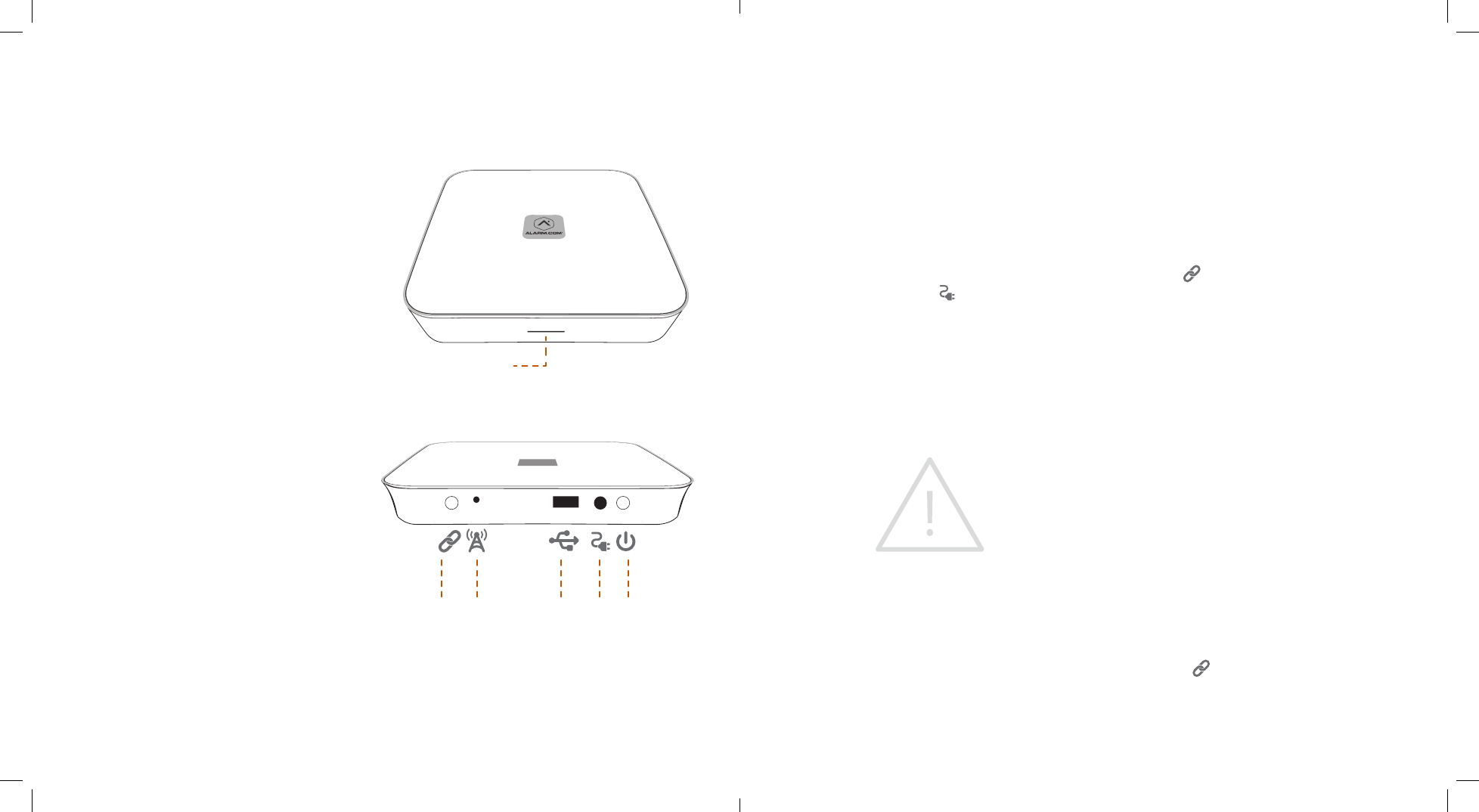
STATUS LIGHT
PAIRING
BUTTON
POWER
BUTTON
DC IN
PORT
EXTERNAL
ANTENNA
OPTIONAL
SERVICE
USB PORT

6 | Alarm.com Hub Install Guide Alarm.com Hub Install Guide | 7
Unpairing Z-Wave Devices (If all Z-Wave
devices were added successfully, skip to
Step 3 below)
• To put the Hub in Unpairing Mode, press and
hold the Pairing button ( ) for ve seconds
until the Status Light ashes orange slowly and
the Hub beeps twice.
• To put your Z-Wave device into Unpairing Mode,
follow the instructions that came with the device.
For many Z-Wave devices the same button is used
for pairing and unpairing.
• When unpairing is successful, the Hub will beep
for one second, and the Hub’s Status Light will
stay solid orange for 120 seconds.
• After a device is unpaired, the Hub automatically
exits Unpairing Mode.
• To pair the device with the Hub, return to the
beginning of Step 2 above.
• To exit Unpairing Mode, press and quickly release
the Pairing button ( ). Alternatively, the Hub will
exit automatically after 120 seconds of inactivity.
Step 3: Pairing Image Sensors
• First remove all batteries from the Image Sensor.
The Image Sensor uses two AA lithium batteries.
NOTE: Do not use lithium-ion batteries, which
can damage the Image Sensor.
• To put the Hub in Pairing Mode, press the Pairing
button ( ) once. The Status Light will start
ashing green slowly and the Hub will beep once.
• To put the Image Sensor in Pairing Mode, simply
insert batteries into the Image Sensor.
• It may take the Hub 20 seconds or longer to pair
with the Image Sensor. If pairing is successful, the
Hub will beep for one second, and the Status Light
will stay solid green for 120 seconds.
• If Image Sensor pairing fails, it may mean the
Image Sensor is not within range of the Hub.
Try moving the Hub closer to the Image Sensor
and repeat Step 3. If problems persist, see
Resetting the Image Sensor in the Advanced
Mode section of this manual.
• To exit Pairing Mode, press and quickly release the
Pairing button ( ). Alternatively, the Hub will
exit automatically after 120 seconds of inactivity.
Step 4: Communication Test
Next, you should run a Communications
Test to ensure the Hub has adequate cellular
signal strength to communicate with the
Alarm.com cloud.
• First, put the Hub in Advanced Mode by pressing
and holding the Pairing button ( ) for 10
seconds. When the Hub enters Advanced Mode,
it will beep three times, and the Status Light will
alternate colors.
• Press and quickly release the Power button ( ).
• This will initiate the Communications Test.
When the test has begun, the Hub will beep six
times and the Status Light will slowly alternate
green and orange ashes.
• When the Communication Test nishes, the Hub
will beep for one second.
• A solid green Status Light indicates a
successful test.
• A solid orange Status Light indicates an
unsuccessful test.
• If the Communications Test fails, try moving the
Hub closer to an exterior wall or window.
Step 5: Finishing Up
• Reconnect the Hub to power (e.g., plug it back in)
if removed during installation.
• Navigate to the Alarm.com Customer Website to
login to your new system. Once you login, make
sure to:
• Conrm your e-mail address and contact
information.
• Add other users to your system (if desired).
• Set up rules and notications so you always
know what’s happening around your home.
• Download the Alarm.com Mobile App
(Available for iPhone, iPad, Android and
Windows Phone).
Powering Down
• Remove the power cable from the back of the
Hub and press the Power button ( ) for four
seconds to power down the Hub.
OPERATING NOTE: Periodically, the Hub’s
Status Light will ash white for up to 60
seconds. This is normal. However, if the light
ashes white for longer than a minute,
contact your service provider.

8 | Alarm.com Hub Install Guide Alarm.com Hub Install Guide | 9
Advanced Mode
This section is for authorized professional installers
and service providers.
The Hub has an Advanced Mode for trouble-
shooting and service. To access features in the
following section, put the Hub in Advanced
Mode by holding down the Pairing button ( )
for 10 seconds. When the Hub enters Advanced
Mode, it will beep three times, and the Status
Light will alternate colors. To exit Advanced Mode,
press and quickly release the Pairing button ( ).
Alternatively, the Hub will exit automatically after
120 seconds of inactivity. From Advanced Mode,
you can perform the following advanced actions.
Z-Wave Replication
This process copies a Z-Wave Network from an old
master node (such as a Panel or Z-Wave controller)
to the Hub.
CAUTION: Z-Wave Replication erases all
currently connected Z-Wave devices.
NOTE: The command to enable or disable
Z-Wave Replication can be sent from the Alarm.
com Dealer Website’s AirFX™ Toolkit. Z-Wave
Replication is only available during the rst 120
seconds after initially powering on the Hub.
• After entering Advanced Mode, press and hold
the Pairing Button ( ) for ve seconds. When
Z-Wave Replication has begun, the Hub Status
Light will blink green slowly and the Hub will
beep four times.
• To cancel Z-Wave Replication, you must
immediately press and release the Pairing
button ( ). This feature is only available
during the rst ve seconds after Z-Wave
Replication has begun.
• When Z-Wave Replication is complete, the Status
Light will shine solid green for 10 seconds and the
Hub will beep for one second.
Factory Resetting
This resets the Hub to its factory settings.
CAUTION: Factory Resetting erases all devices
and settings.
NOTE: The command to enable or disable
Factory Resetting can be sent from the
Alarm.com Dealer Website’s AirFX Toolkit.
Factory Resetting is only available during
the rst 120 seconds after initially powering
on the Hub.
• After entering Advanced Mode, press and hold
the Pairing button ( ) for 10 seconds. When the
reset process has begun, the Status Light will blink
orange slowly and the Hub will beep ve times.
• To cancel Factory Resetting, you must
immediately press and release the Pairing
button ( ). This feature is only available
during the rst ve seconds after Factory
Resetting has begun.
• When Factory Resetting is complete, the Status
Light will shine solid orange for 10 seconds.
• Next, contact Alarm.com Customer Support to
reinitialize the Hub.
Communications Test
This tests the Hub’s connection to the
Alarm.com cloud.
• After entering Advanced Mode, press and
immediately release the Power button ( ).
• When the test has begun, the Hub will beep
six times and the Status Light will slowly
alternate green and orange ashes.
• When the Communication Test nishes, the Hub
will beep for one second.
• A solid green Status Light indicates a
successful test.
• A solid orange Status Light indicates an
unsuccessful test.
• If the Communications Test fails, try moving the
Hub closer to an exterior wall or window.
Resetting the Image Sensor
This resets the Image Sensor to its factory settings.
This is helpful before pairing if the Image Sensor
has been previously used with another gateway
or panel.
• Ensure that the Image Sensor is not connected to
another active network.
• Locate the reset hole on the front of the Image
Sensor. Use a paper clip to push the reset button
for 10 seconds. When the Image Sensor has been
reset, a light in the IR slot directly below the reset
hole will ash quickly.
• For more Image Sensor Information, see the Image
Sensor Installation Guide.
10 | Alarm.com Hub Install Guide Alarm.com Hub Install Guide | 11
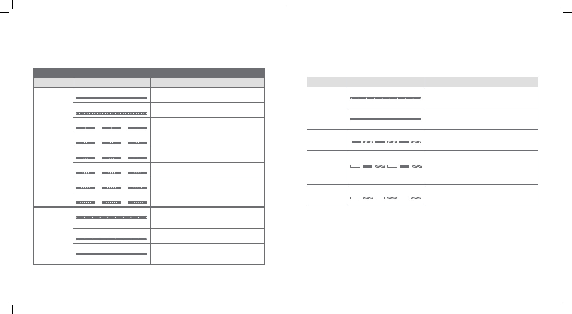
Status Light Denitions
User Mode Cellular Hub
LIGHT COLOR LIGHT PATTERN/BEEPS MEANING
WHITE
Solid Hub powered on and connected to Alarm.com
Fast blink No cellular signal strength. Hub not connected
to Alarm.com
One blink Signal strength inadequate (1 out of 6 bars).
Hub not connected to Alarm.com
Two blinks Minimum recommended signal strength (2 out of
6 bars). Hub not connected to Alarm.com
Three blinks Signal strength 3 out of 6 bars. Hub not connected
to Alarm.com
Four blinks Signal strength 4 out of 6 bars. Hub not connected
to Alarm.com
Five blinks Signal strength 5 out of 6 bars. Hub not connected
to Alarm.com
Six blinks Signal strength 6 out of 6 bars. Hub not connected
to Alarm.com
GREEN
Slow blink
One beep
Hub is in Pairing Mode
Fast blink Device found, attempting to pair
Solid
120 seconds; One second beep
Device successfully added
LIGHT COLOR LIGHT PATTERN/BEEPS MEANING
ORANGE
Slow Blink
Two beeps
Hub is in Unpairing Mode
Solid
120 seconds; One second beep
Device successfully removed
GREEN
&
ORANGE
Alternating Device already in network
WHITE
&
GREEN
&
ORANGE
Alternating; Three beeps Hub turned on OR Hub entering OR exiting
Advanced Mode.
WHITE
&
ORANGE
Alternating Battery powered
12 | Alarm.com Hub Install Guide Alarm.com Hub Install Guide | 13
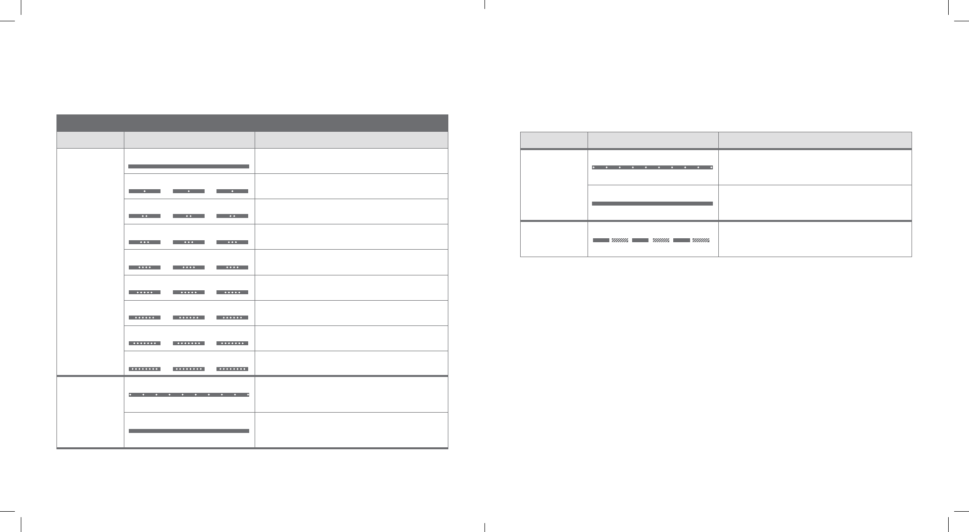
Advanced Mode Cellular Hub
LIGHT COLOR LIGHT PATTERN/BEEPS MEANING
WHITE
Solid No errors or status messages
One blink No Z-Wave nodes
Two blinks SIM card missing
Three blinks Trying to register with HSPA/CDMA network
Four blinks Connected to HSPA/CDMA network. Cannot
connect to Alarm.com
Five blinks Radio not working
Six blinks Fixing unusual ACK condition with HSPA/CDMA
network
Seven blinks No Z-Wave Home ID
Eight blinks Account setup error
GREEN
Slow blink
Four beeps
Z-Wave replication initiated
Solid
10 seconds; One second beep
Z-Wave replication completed
Status Light Denitions (Continues)
LIGHT COLOR LIGHT PATTERN/BEEPS MEANING
ORANGE
Slow blink
Five beeps
Factory resetting initiated
Solid
10 seconds; One second beep
Factory resetting, Hub will reset.
GREEN
&
ORANGE
Alternating
Six beeps
Communication Test Mode initiated

14 | Alarm.com Hub Install Guide Alarm.com Hub Install Guide | 15
Regulatory & CerticationsRegulatory & Certications
Changes or modications not expressly approved by
Alarm.com can void the user’s authority to operate
the equipment.
This equipment has been tested and found to
comply with the limits for a Class B digital device,
pursuant to part 15 of the FCC Rules. These limits are
designed to provide reasonable protection against
harmful interference in a residential installation. This
equipment generates, uses, and can radiate radio
frequency energy and, if not installed and used in
accordance with the instructions, may cause harmful
interference to radio communications. However, there
is no guarantee that interference will not occur in a
particular installation. If this equipment does cause
harmful interference to radio or television reception,
which can be determined by turning the equipment
o and on, the user is encouraged to try to correct
the interference by one or more of the following
measures:
• Re-orient or relocate the receiving antenna.
• Increase the separation between the equipment and
receiver.
• Connect the equipment to an outlet on a circuit
dierent from that which the receiver is connected
• Consult the dealer or an experienced radio/TV
technician for help.
This equipment complies with the FCC RF radiation
exposure limits set forth for an uncontrolled
environment. This equipment should be installed and
operated with a minimum distance of 20 centimeters
between the radiator and your body.
Under Industry Canada regulations, this radio
transmitter may only operate using an antenna of a
type and maximum (or lesser) gain approved for the
transmitter by Industry Canada.
Conformément à la réglementation d’Industrie
Canada, le présent émetteur radio peut fonctionner
avec une antenne d’un type et d’un gain maximal
(ou inférieur) approuvé pour l’émetteur par Industrie
Canada.
This device complies with Industry Canada licence-
exempt RSS standard(s). Operation is subject to the
following two conditions: (1) this device may not
cause interference, and (2) this device must accept
any interference, including interference that may
cause undesired operation of the device.
Le présent appareil est conforme aux CNR d’Industrie
Canada applicables aux appareils radio exempts
de licence. L’exploitation est autorisée aux deux
conditions suivantes : (1) l’appareil ne doit pas
produire de brouillage, et (2) l’utilisateur de l’appareil
doit accepter tout brouillage radioélectrique
subi, même si le brouillage est susceptible d’en
compromettre le fonctionnement.,
This device complies with Part 15 of the FCC Rules.
Operation is subject to the following two conditions:
(1) this device may not cause harmful interference,
and (2) this device must accept any interference
received, including interference that may cause
undesired operation.
FCC ID: YL6143NK100T
IC: 9111A-143NK100T
Hub Specications
Power Requirements 5V nominal
Standby current 90mA (45mA in PowerSave Mode)
Peak Current 1.5 A
Max. Voltage Protection 28V
Operating Voltage 4.6V - 5.53V
Operating Temperature 32 to 120°F (0 to 49°C)
Storage Temperature -30 to 140°F (-34 to 60°C)
Max. Relative Humidity 90% non-condensing
Module Dimensions 13.75 cm x 14.25 cm
Housing Dimensions 16 cm x 16 cm
Cellular Network Dual Band CDMA/1xRTT (3G) or
Dual Band HSPA 2G/3G (850/1900 MHz)
Battery Specications
Type Lithium Ion
Rated Capacity 1300 mAh
Charging Temperature 0 to 45°C
Discharge Temperature -20 to 60°C
Storage Temperature 1 year at +15 to +35°C
1 month at -20 to +60°C
3 months at -20 to +45°C
Max. Relative Humidity 65 ± 20%
Listings UL 1642
16 | Alarm.com Hub Install Guide
Copyright © 2015 Alarm.com. All rights reserved. Alarm.com and the Alarm.com Logo are registered trademarks of Alarm.com.