Alcatel Canada 24T07A01D22D 7390 24 GHz Co-Pol RT User Manual NT Manual pages 51 to 75
Alcatel Canada Inc 7390 24 GHz Co-Pol RT NT Manual pages 51 to 75
UserManual.wiki
>
Alcatel Canada
>
24T07A01D22D User Manual
>
NT Manual pages 51 to 75
Contents
1.
NT Manual pages 1 to 25
2.
NT Manual pages 26 to 35
3.
NT Manual pages 36 to 50
4.
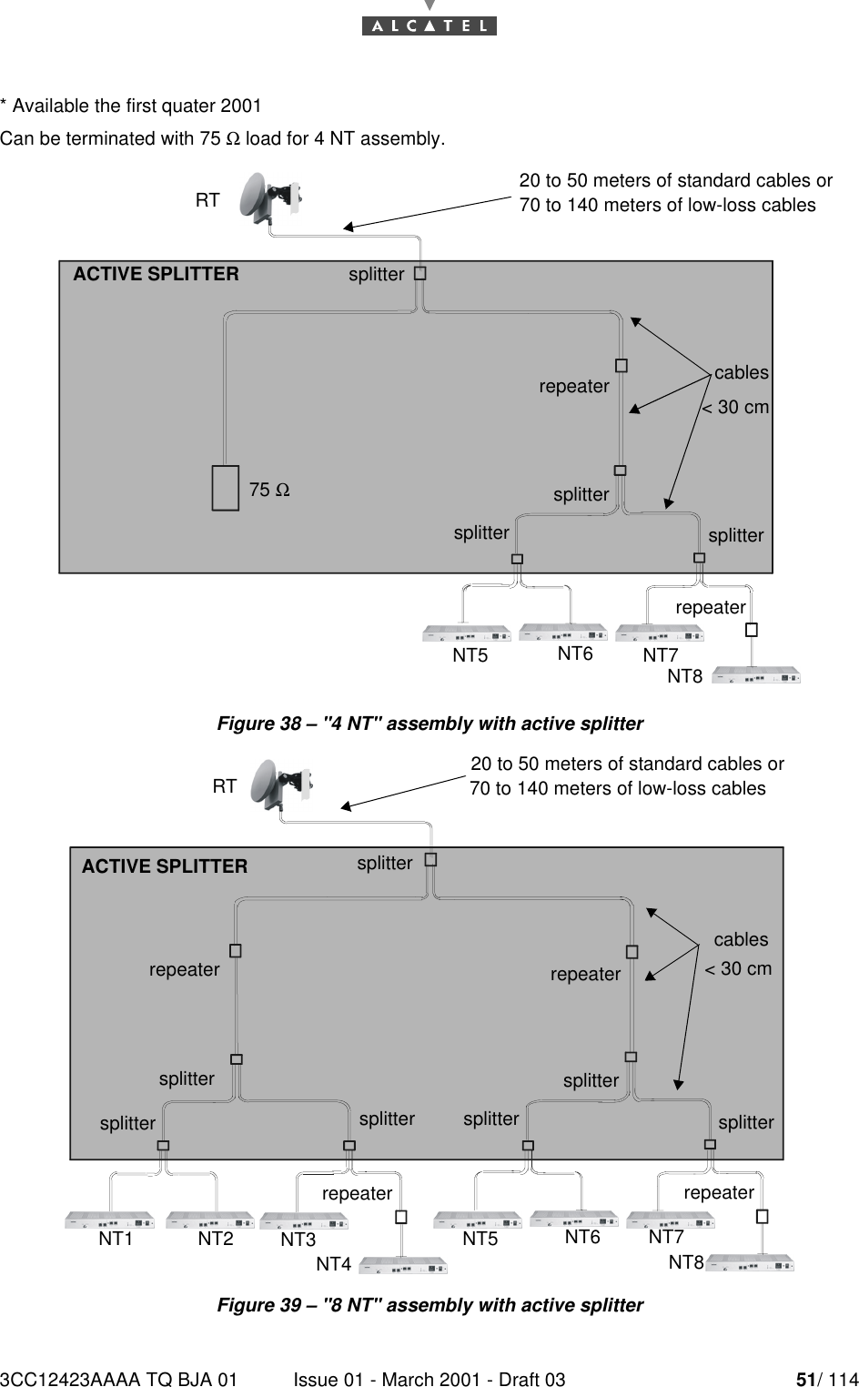
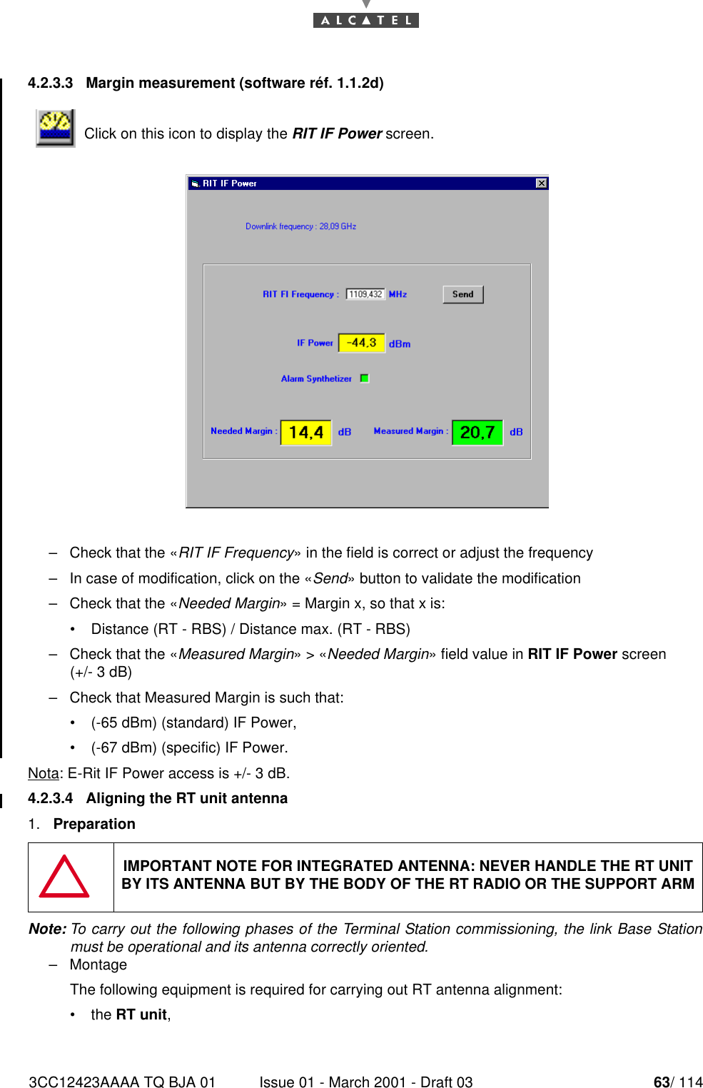
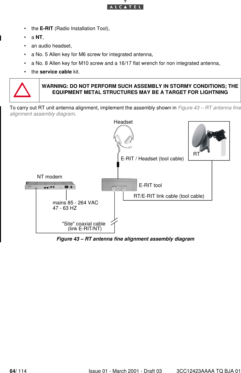
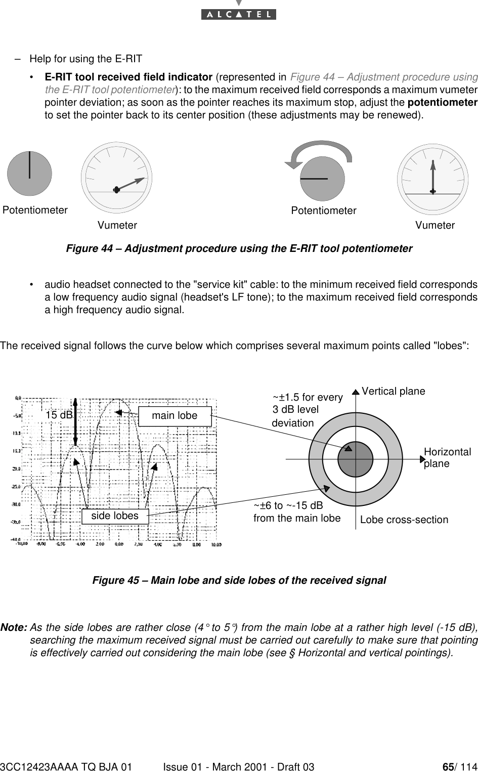
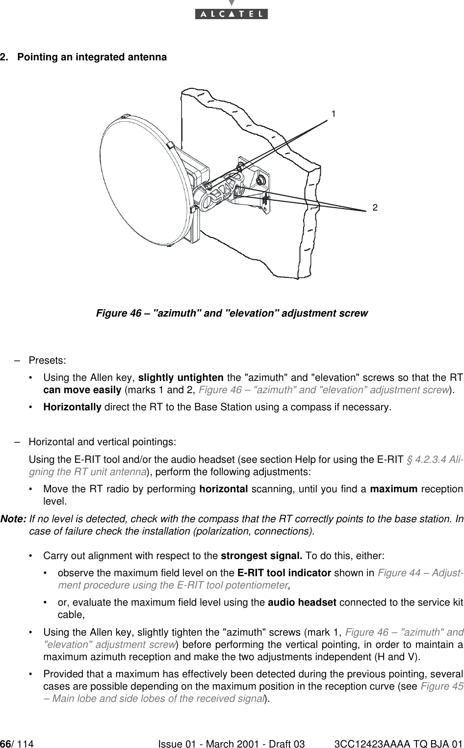
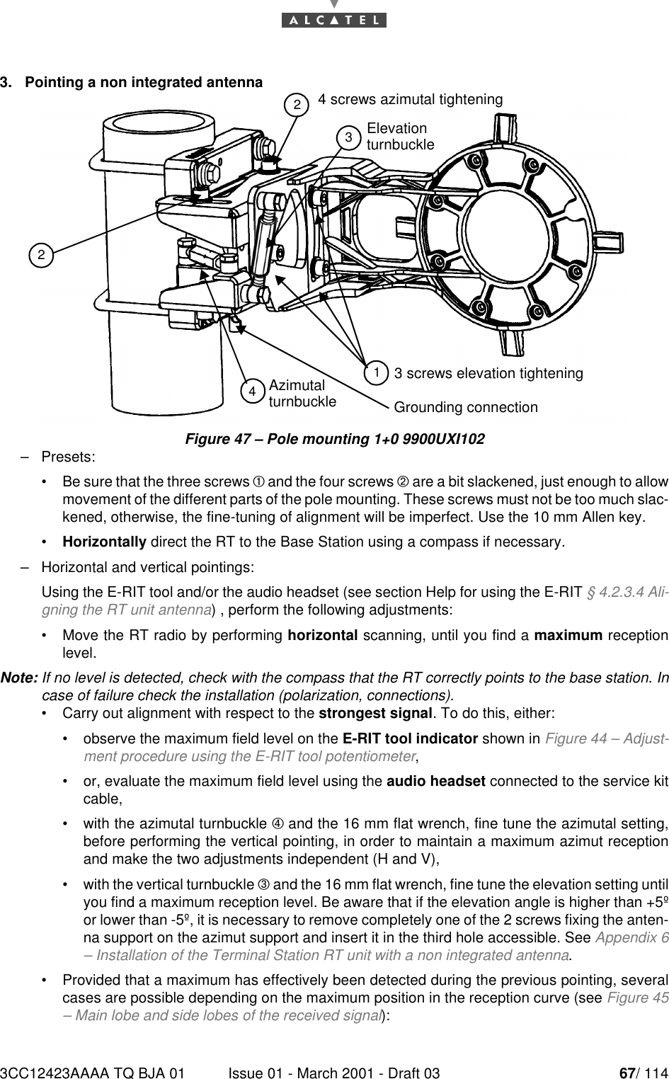
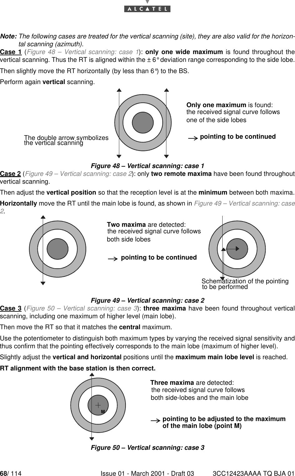
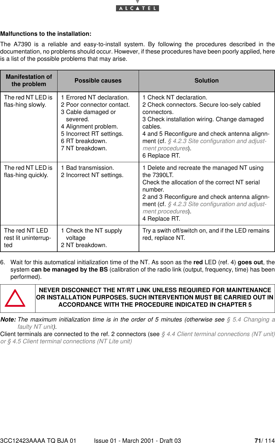
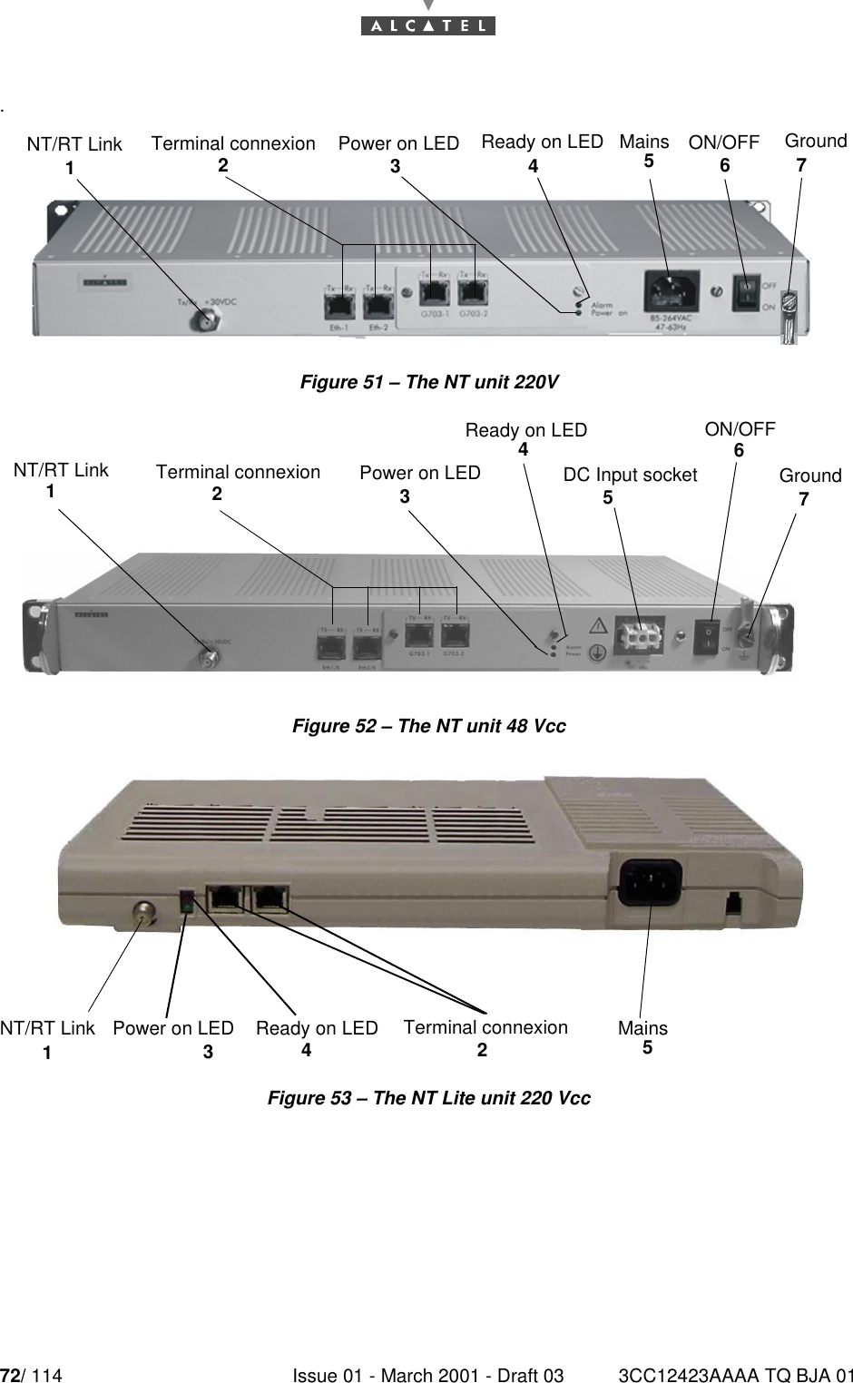
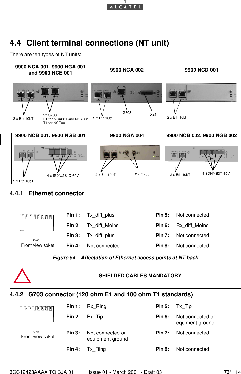
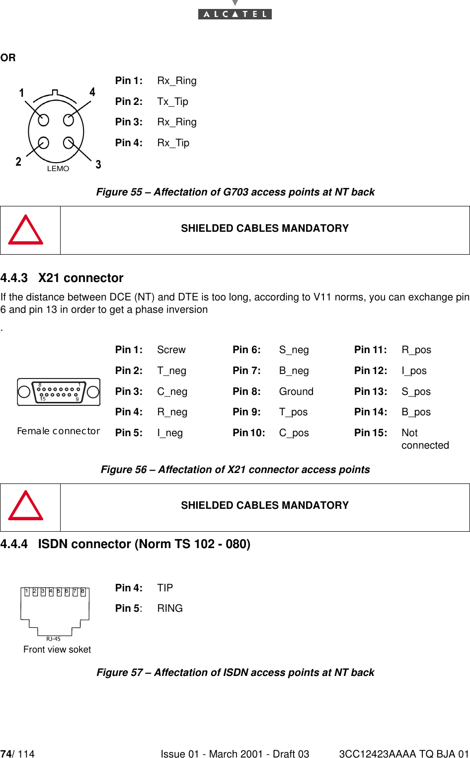
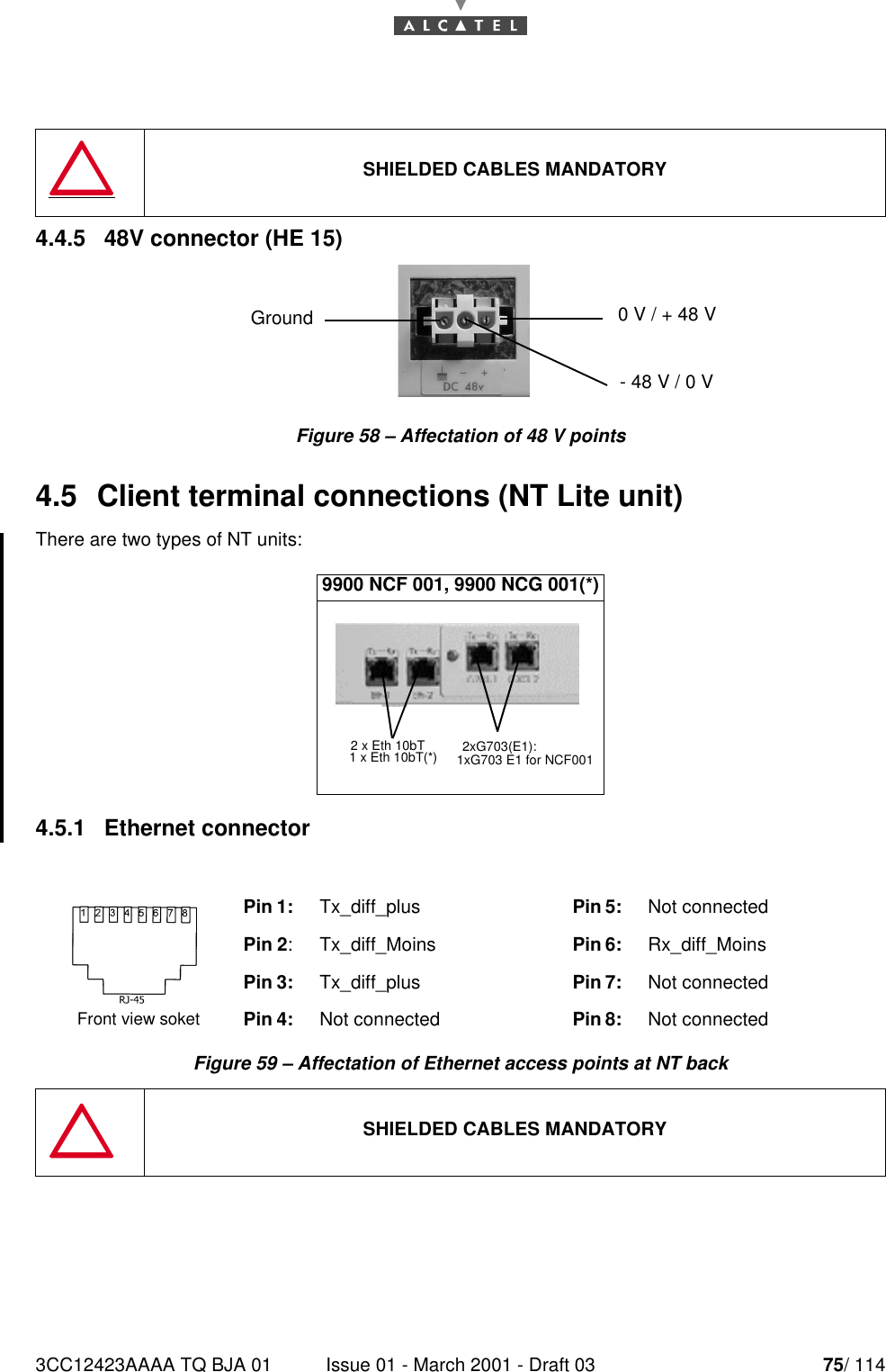
NT Manual pages 51 to 75
5.
NT Manual pages 76 to 100
6.
NT Manual pages 101 to 114
NT Manual pages 51 to 75
Navigation menu
Upload a User Manual
Namespaces
Wiki Guide
HTML
PDF
Info
Views
User Manual
Discussion / Help
Navigation