Alcatel Canada 24T07A01D22D 7390 24 GHz Co-Pol RT User Manual NT Manual pages 51 to 75
Alcatel Canada Inc 7390 24 GHz Co-Pol RT NT Manual pages 51 to 75
Contents
NT Manual pages 51 to 75
3CC12423AAAA TQ BJA 01 Issue 01 - March 2001 - Draft 03 51/ 114
52
* Available the first quater 2001
Can be terminated with 75 Ω load for 4 NT assembly.
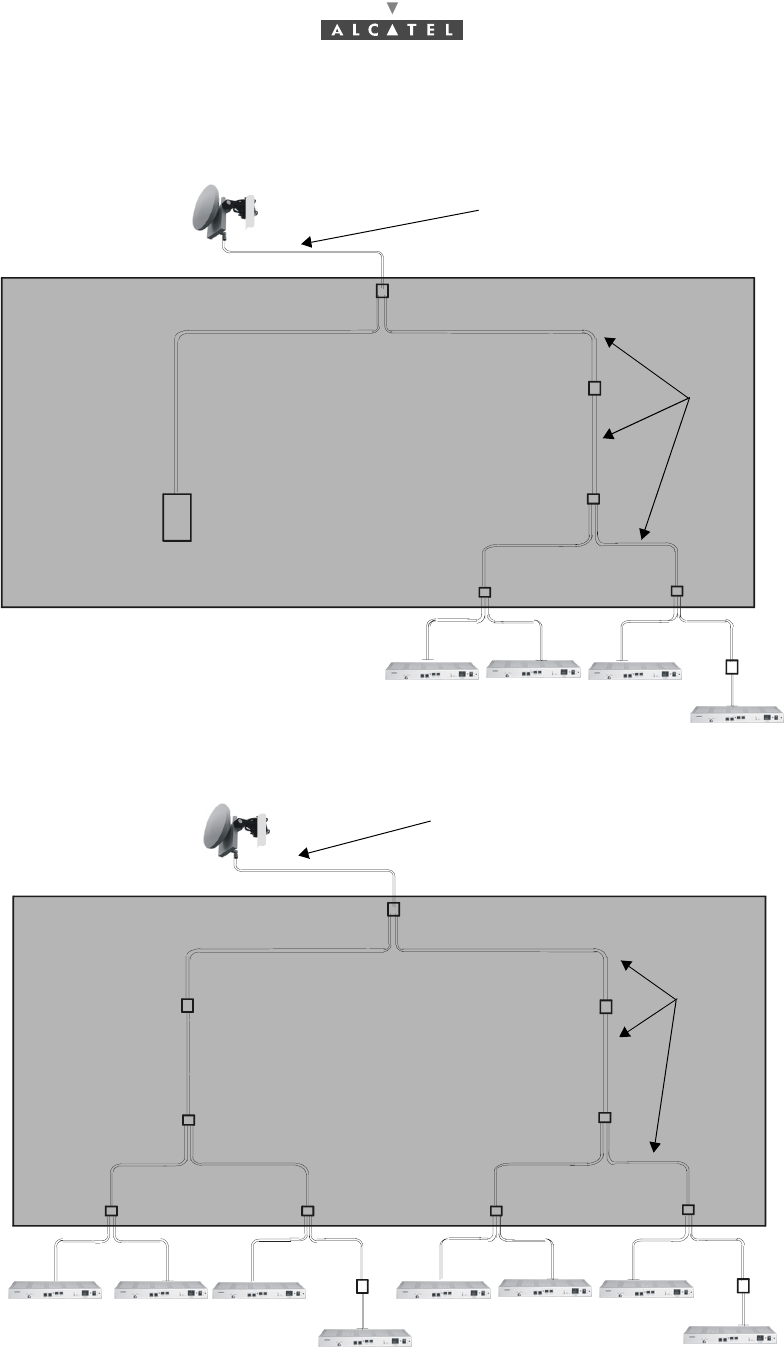
Figure 38 – "4 NT" assembly with active splitter
Figure 39 – "8 NT" assembly with active splitter
20 to 50 meters of standard cables or
70 to 140 meters of low-loss cables
splitter
repeater
splitter
repeater
75 Ω
splitter splitter
cables
NT5 NT6 NT7
NT8
RT
ACTIVE SPLITTER
< 30 cm
20 to 50 meters of standard cables or
70 to 140 meters of low-loss cables
splitter
splitter
repeater
ACTIVE SPLITTER
splitter
cables
RT
NT1 NT2 NT3
NT4
NT5 NT6 NT7
NT8
splitter
splitter
splitter
splitter
repeater
repeater
repeater
< 30 cm

52/ 114 Issue 01 - March 2001 - Draft 03 3CC12423AAAA TQ BJA 01
52
PAGE INTENTIONALLY LEFT BLANK

3CC12423AAAA TQ BJA 01 Issue 01 - March 2001 - Draft 03 53/ 114
78
4 Commissioning the 7390 TS Terminal Station
4.1 Purpose
The purpose of this task is to carry out:
–site adjustment of the RT unit (also called RT or RT radio),
–initialization and configuration of the RT unit and NT unit parameters,
–checking and validation of the installed parameters before rendering the equipment operational.
4.2 Commissioning the RT unit
4.2.1 Equipment required
To configure the parameters and carry out site adjustment of the RT unit, the following equipment is
required:
–the RT unit,
–the E-RIT tool (Radio Installation Tool) cf. § 4.2.2 E-RIT Tool;
RIT software installation (Ref. : 3CC11826 Axxx):
•DLL software, Driver I2C Win95/98 NT,
•Installation kit RT 7390WW (3CC10786Axxx 02),
•Setup.
–one tool cable set (see Figure 41 – RT «N» connector configuration setup diagram and
Figure 43 – RT antenna fine alignment assembly diagram),
–one audio-head set (see Figure 43 – RT antenna fine alignment assembly diagram),
–one No.5 Allen key for M6 screw for an integrated antenna
–one No. 8 Allen key for M10 screw and one 16/17 flat wrench for non integrated antenna,
–the RT installation and programming software pre-installed on a portable PC,
–CD-ROM containing the data pre-recorded by the network operator,
–a PC fitted with the RT unit initialization and programming software; the PC should have the fol-
lowing minimum characteristics:
•Microprocessor: 500 MHz Pentium III,
•RAM Memory 64 MB,
•Hard disk: 4 GB,
•Monitor SVGA (800 x 600),
•Windows 9x /NT4. (Service pack 3 or above).
54/ 114 Issue 01 - March 2001 - Draft 03 3CC12423AAAA TQ BJA 01
78
4.2.2 E-RIT Tool
The E-RIT is used (only if RT «N»):
–as an interface between the PC and the RT unit: it receives the information necessary to the ini-
tialization and programming of the RT from the PC and transmits it to the RT unit;
–to implement optimal alignment of the antenna facing the Base Station. This function is provided
by the Received Signal Level control system (visual and/or audible) of the E-RIT.
The E-RIT tool is equipped with a sheath to protect it from impacts and allowing the operator hands-free
operation.
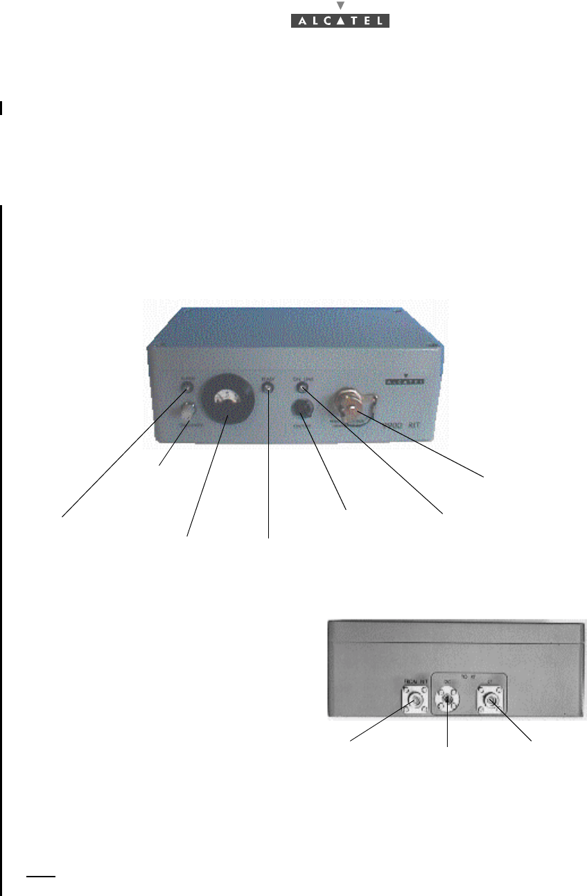
Figure 40 – RIT tool
Note: Let the E-RIT warm up (-10/+55 °C range) after it storage in extreme temperatures (-40/+70 °C).
Rear view of E-RIT
Front view of E-RIT
Sensitivity
potentiometer
Field Gauge
for received level
Alarm indicator On/Off switch On line indicator
PC and headset
cable connector
Receiving indicator
is off in case field is
exceeded: level >
-10dbm
N connector to
NT
BNO connector
to RT «N» unit N connector to
RT unit
only
3CC12423AAAA TQ BJA 01 Issue 01 - March 2001 - Draft 03 55/ 114
78
4.2.3 Site configuration and adjustment procedures
4.2.3.1 Configuration setting of the 7390RT parameters
To carry out RT radio programming, implement FIRST the assembly shown in Figure 41 – RT «N»
connector configuration setup diagram.
Note: The radio configuration requires the information featuring in the installation instructions (see
Appendix 1 – 7390 TS installation sheet), duly completed in advance. This will be used to define
the parameters required by the configuration application.
Note: It is recommended that this task be carried out indoors. The use of the portable PC in inclement
weather conditions (rain, snow, etc.) is not advisable.
Note: Safety recommendations listed in section 1.3 being followed, it is not necessary to establish spe-
cial grounding connection for the NT casing. Therefore, it is performed via the 3-wire mains cord.
FOR THE ASSEMBLIES DESCRIBED IN THE FOLLOWING PARAGRAPHS,
CONNECT THE NT TO THE MAINS SUPPLY LAST OF ALL, ONCE ALL THE
OTHER CONNECTIONS HAVE BEEN MADE BEFORE.
56/ 114 Issue 01 - March 2001 - Draft 03 3CC12423AAAA TQ BJA 01
78
A ) RT «N» connector
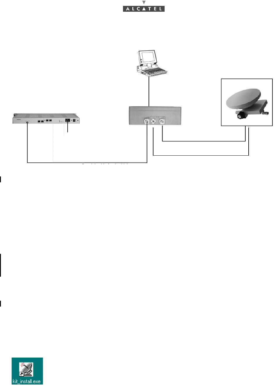
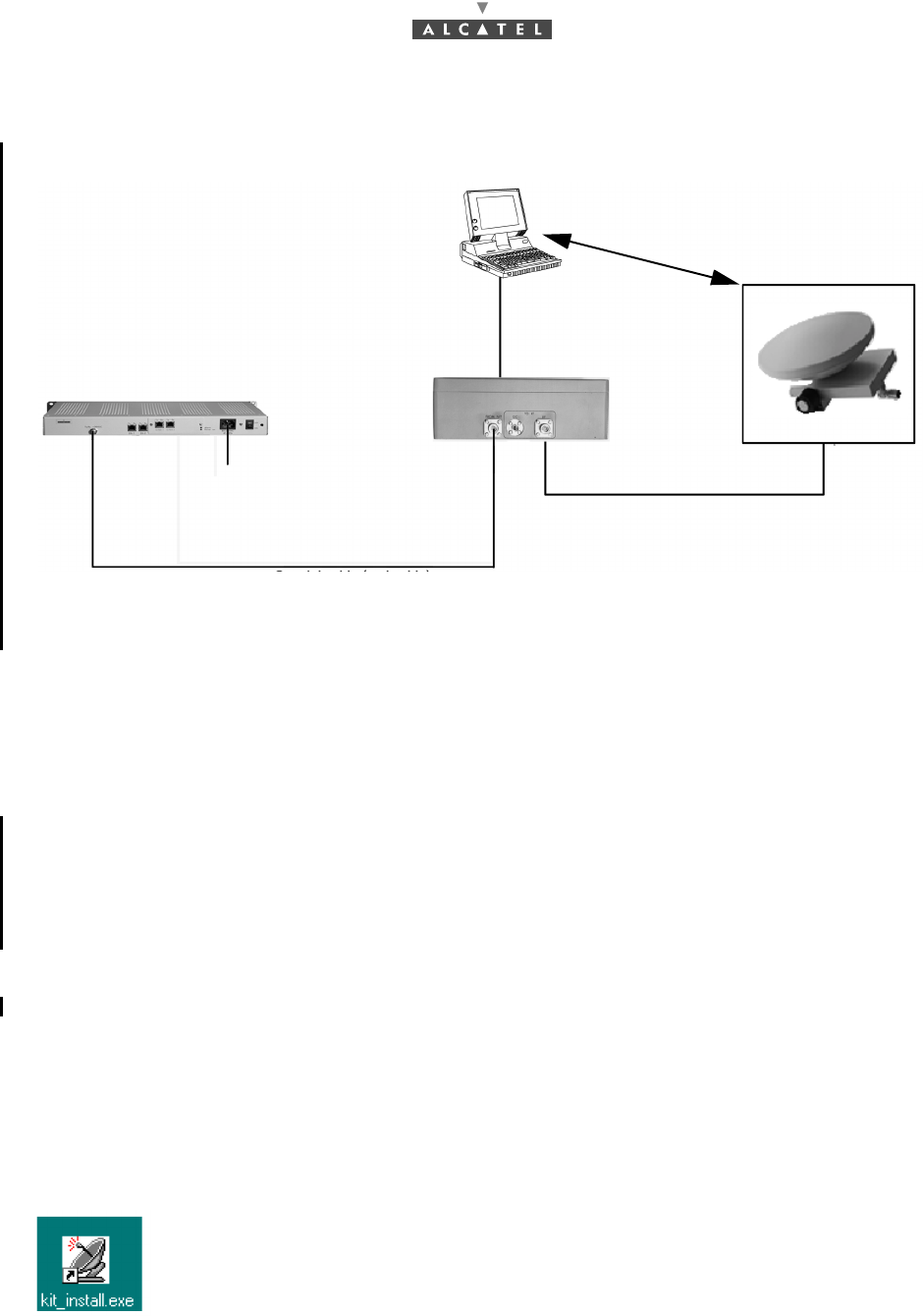
Figure 41 – RT «N» connector configuration setup diagram
Stages
1. Connect the cables of the configuration tools (cables and tools delivered with the equipment):
•between the RT unit and the E-RIT tool: the RT/E-RIT link coaxial cable ("N" type connectors
at both ends (75Ω),
•between the RT unit and the E-RIT tool: the data transfer bus («N» type connectors at both
ends),
•between the portable PC and the E-RIT tool,
•between the E-RIT tool and the NT: coaxial cable ("N" type connector at the E-RIT (75Ω) and
"F" type connector at the NT),
•between the NT and the mains power supply: mains connection cable (to connect last).
2. Power-up the assembly:
•power-up the NT,
•power-up the PC,
•power-up the E-RIT tool.
3. Run the radio configuration application by clicking on its "kit-install.exe" icon on the PC Windows
desktop.
To run the kit_install.exe application from the Windows desktop, double-click on the icon
shown opposite. The first configuration screen then appears.
Note: The user of the installation software must be familiar with the operation of software in the Win-
dows 95, 98 or NT environments.
RT/E-RIT link (tool cable)
I2C bus (tool cable)
Coaxial cable (tool cable) or "site" cable
mains 85 - 264 VAC
NT
E-RIT tool RT «N»
E-RIT/PC link
(tool cable)
3CC11056Axxx
47 - 63 HZ
«N» Plug
Portable computer
3CC12423AAAA TQ BJA 01 Issue 01 - March 2001 - Draft 03 57/ 114
78
B) RT «F» connector
Figure 42 – RT «F» connector configuration setup diagram
Stages
1. Connect the cables of the configuration tools (cables and tools delivered with the equipment):
•between the RT unit and the E-RIT tool: the RT/RIT link coaxial cable ("F" type connectors at
both ends (75Ω),
•between the portable PC and the E-RIT tool,
•between the E-RIT tool and the NT: coaxial cable ("N" type connector at the E-RIT (75Ω) and
"F" type connector at the NT),
•between the NT and the mains power supply: mains connection cable (to connect last),
•between the E-RIT/PC link and RT «F» connector the data transfer bus (RS232) with BR2 /
DB9 cable.
2. Power-up the assembly:
•power-up the NT,
•power-up the PC,
•power-up the E-RIT tool.
3. Run the radio configuration application by clicking on its "kit-install.exe" icon on the PC Windows
desktop.
To run the kit_install.exe application from the Windows desktop, double-click on the icon
shown opposite. The first configuration screen then appears.
Note: The user of the installation software must be familiar with the operation of software in the Win-
dows 95, 98 or NT environments.
RT/E-RIT link (tool cable)
Coaxial cable (tool cable) or "site" cable
mains 85 - 264 VAC
NT
E-RIT tool RT «F»
E-RIT/PC link
(tool cable)
3CC11056Axxx
47 - 63 HZ
«F» Plug
RS232
Portable computer
DB9
BR2
58/ 114 Issue 01 - March 2001 - Draft 03 3CC12423AAAA TQ BJA 01
78
4.2.3.2 RT configuration (maximum distance according to a NT-RBS)
The steps of RT configuration are:
–geographic area,
–RF gain correctio calculation,
–cable gain correction for,
•mono NT software ref.:1.1.2d,
•two NT software ref.:1.0.9a,
•4/8 NT software ref.:1.1.2d.
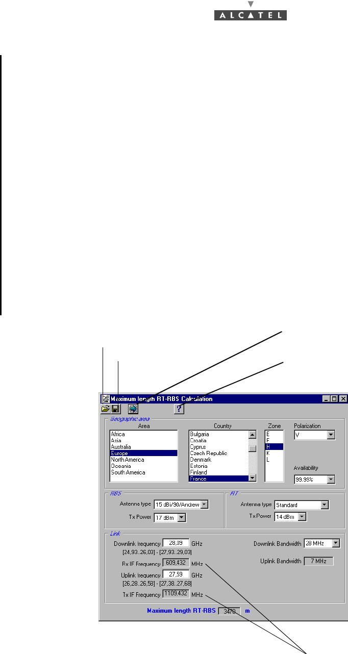
Geographic area
Once the configuration application has been run, the radio parameters must be supplied.
The radio configuration parameters can be supplied to the software in two different ways:
•in the form of a configuration file stored on an IT medium (floppy disk, CD-ROM or other); the
parameters obtained like this may, if necessary, be subsequently modified,
•by direct input of parameters via configuration screens.
In the case of data saved in a file, insert the IT medium in the PC and transfer the contents of the file to
the installation software.
Click here to go to the next screen
Select language and display the
Click here to define the
configuration file path
Save
software version
Only for software ref.: 1.1.2d
3CC12423AAAA TQ BJA 01 Issue 01 - March 2001 - Draft 03 59/ 114
78
In the case of the parameters being directly entered, follow the RT radio programming stages described
below:
•Calculate the maximum RT-RBS distance (cf. A),
•Calculate the gain corrections (cf. B),
Once the parameters have been entered, the configuration must be sent to the RT radio unit.
Note: To ensure optimum radio link quality, define with care the parameter values in compliance with
the real environmental characteristics.
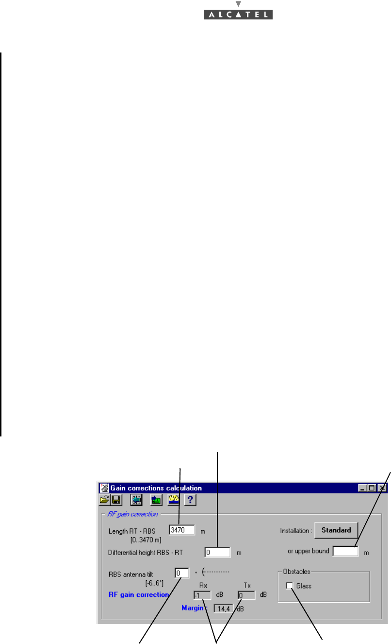
RF gain correction calculation
Note: does not depend on RT / NT topology
To define the value of the parameters to be entered in the "Gain corrections calculation" screen, use the
installation sheet (see Appendix 1 – 7390 TS installation sheet), complemented by the Radio Planning.
The RT-RBS distance must be compatible with the value defined in the previous screen.
As the software parameters are entered, the software carries out the gain correction calculations.
If the parameters cannot be accepted, the background colors of the Rx and Tx gain connection windows
change to red. If the values are beyond the system capabilities, all the windows are emptied of their
contents and are grayed-out; it is then necessary to recommence the input starting with the first RT-RBS
distance parameter.
For the RT-RBS distance, it must be to within the following margins:
–100 m < D < 200 m, 20 m max. error
–200 m < D < 400 m, 40 m max. error
–400 m < D < 800 m, 80 m max. error
–D > 800 m 100 m max. error
Enter the RT-RBS length Enter the estimated max.
Enter the RBS antenna tilt Enter the nature of
Automatic gain
differential height
correction calculation any Obstacles
Enter the Differential height (to within 10%)
60/ 114 Issue 01 - March 2001 - Draft 03 3CC12423AAAA TQ BJA 01
78
Cable gain correction
For the cable gain correction calculation, there are three possible scenarios depending on the installation
topology: Mono NT, two NTs or Multi NTs.
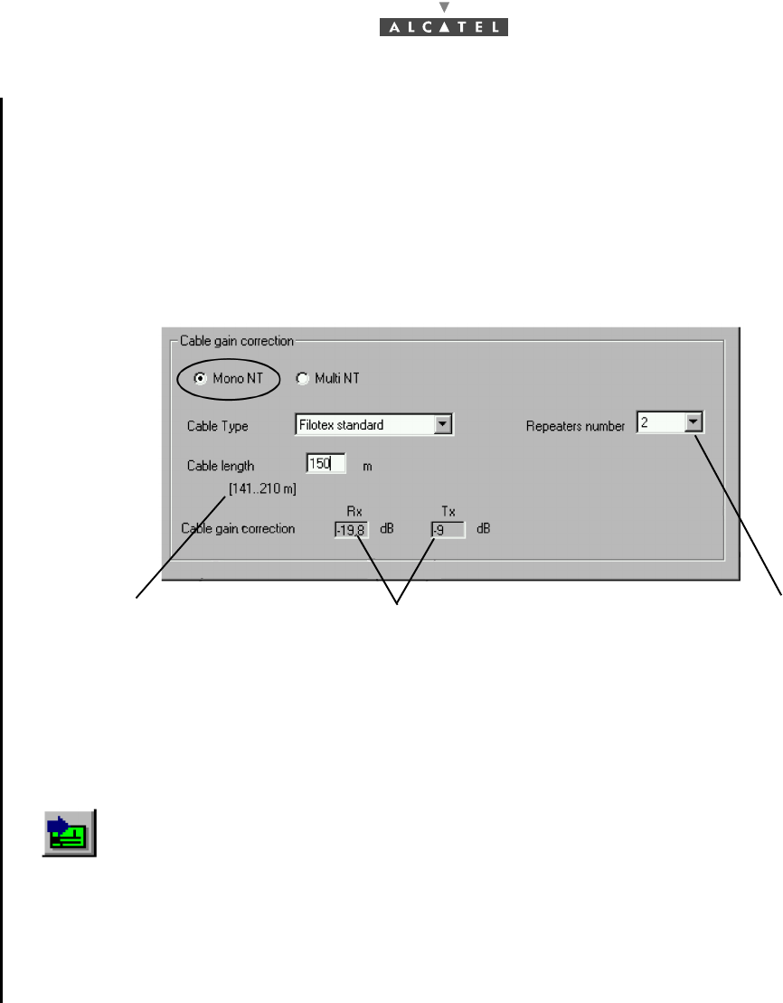
1. Mono NT software ref.: 1.1.2d
Cable gain correction in the case of Mono NT, the screen appears as follows, once Mono NT has
been selected:
The cable length indicated is the total length including the free part and the part imposed by the topology.
The field in brackets on the screen is defined as follows:
minimum value = N x 70 m (N number of repeater),
maximum value = N+1 x 70 m (N number of repeater),
The length adjustment is between 1 m and the maximum length of the first segment with respect to the
cable selected (70 or 210 m).
The software will calculate automatically with respect to the entire set of parameters the corrections to
be made.
Click here to define the
Total cable length field Gain correction calculated
automatically by the software
number of repeaters
(0,1 or 2)
3CC12423AAAA TQ BJA 01 Issue 01 - March 2001 - Draft 03 61/ 114
78
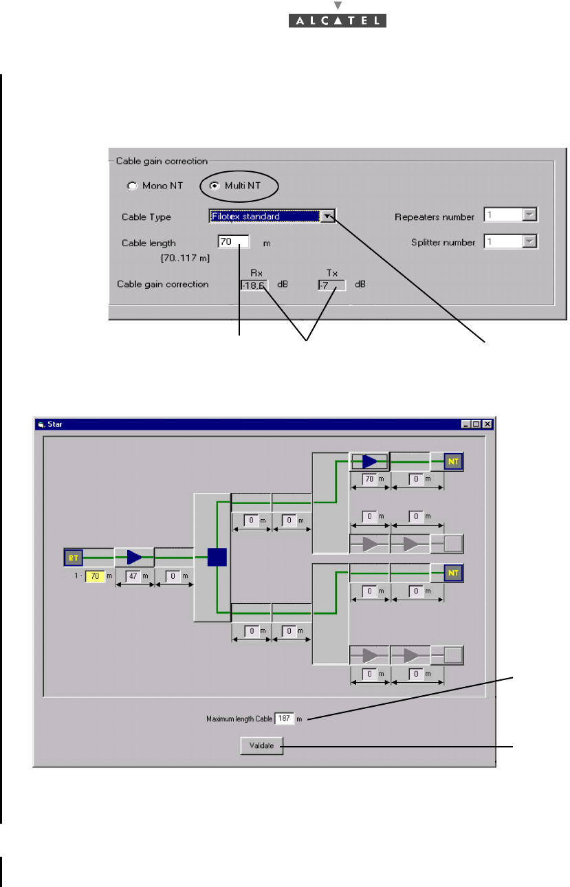
2. Two NT software ref.: 1.0.9a
Cable gain correction in the case of two NT: once the data presented in the Star screen is validated,
the following screen appears:
In the case of two-NT configuration, the following screen appears, once two-NT has been selected:
This screen is used to define the installation topology. Depending on the topology, the total maximum
length (incorporating the imposed part and the free part) is displayed.
Sending the configuration to the RT radio unit
Once the calculations have been made, click on the icon "data send" shown here, that is at the top of
the Gain corrections calculation screen, for the values to be acknowledged by the RT.
Select the cable type
Automatic calculation of
Enter the cable length to within 1.5 m
per segment, 5 m for the total length the cable gain correction
Maximum total length
Click here to validate
once the topology has
been defined
62/ 114 Issue 01 - March 2001 - Draft 03 3CC12423AAAA TQ BJA 01
78
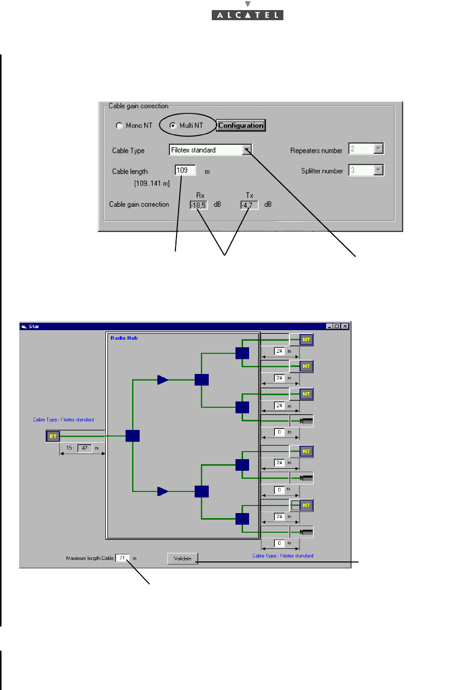
3. 4/8 NT software ref.: 1.1.2d
Cable gain correction in the case of multi NT: once the data presented in the Star screen is validated,
the following screen appears:
In the case of multi-NT configuration, the following screen appears, once multi-NT has been selected:
This screen is used to define the installation topology. Depending on the topology, the total maximum
length (incorporating the imposed part and the free part) is displayed.
Sending the configuration to the RT radio unit
Once the calculations have been made, click on the icon "data send" shown here, that is at the top of
the Gain corrections calculation screen, for the values to be acknowledged by the RT.
Select the cable type
Automatic calculation of
Enter the cable length to within 1.5 m
per segment, 5 m for the total length the cable gain correction
Maximum total length
Click here to validate
once the topology has
been defined
3CC12423AAAA TQ BJA 01 Issue 01 - March 2001 - Draft 03 63/ 114
78
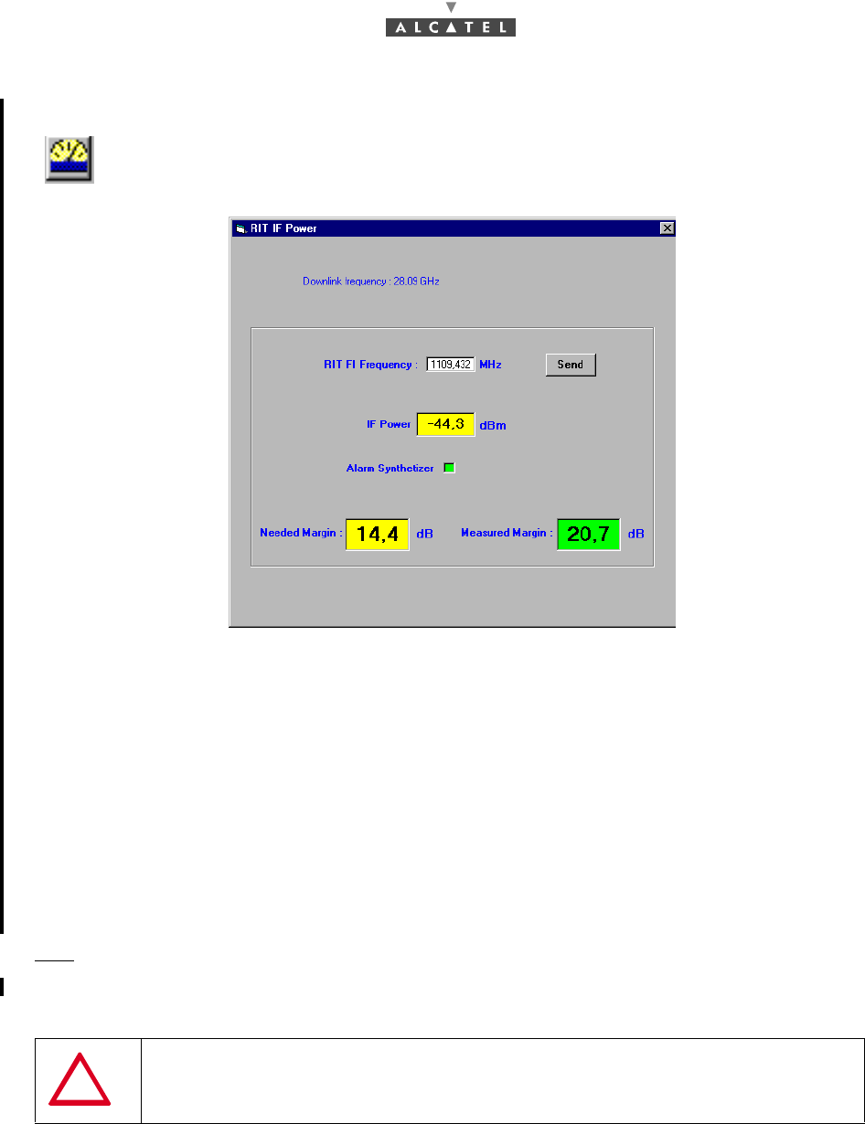
4.2.3.3 Margin measurement (software réf. 1.1.2d)
Click on this icon to display the RIT IF Power screen.
–Check that the «RIT IF Frequency» in the field is correct or adjust the frequency
–In case of modification, click on the «Send» button to validate the modification
–Check that the «Needed Margin» = Margin x, so that x is:
•Distance (RT - RBS) / Distance max. (RT - RBS)
–Check that the «Measured Margin» > «Needed Margin» field value in RIT IF Power screen
(+/- 3 dB)
–Check that Measured Margin is such that:
•(-65 dBm) (standard) IF Power,
•(-67 dBm) (specific) IF Power.
Nota: E-Rit IF Power access is +/- 3 dB.
4.2.3.4 Aligning the RT unit antenna
1. Preparation
Note: To carry out the following phases of the Terminal Station commissioning, the link Base Station
must be operational and its antenna correctly oriented.
–Montage
The following equipment is required for carrying out RT antenna alignment:
•the RT unit,
IMPORTANT NOTE FOR INTEGRATED ANTENNA: NEVER HANDLE THE RT UNIT
BY ITS ANTENNA BUT BY THE BODY OF THE RT RADIO OR THE SUPPORT ARM
64/ 114 Issue 01 - March 2001 - Draft 03 3CC12423AAAA TQ BJA 01
78
•the E-RIT (Radio Installation Tool),
•a NT,
•an audio headset,
•a No. 5 Allen key for M6 screw for integrated antenna,
•a No. 8 Allen key for M10 screw and a 16/17 flat wrench for non integrated antenna,
•the service cable kit.
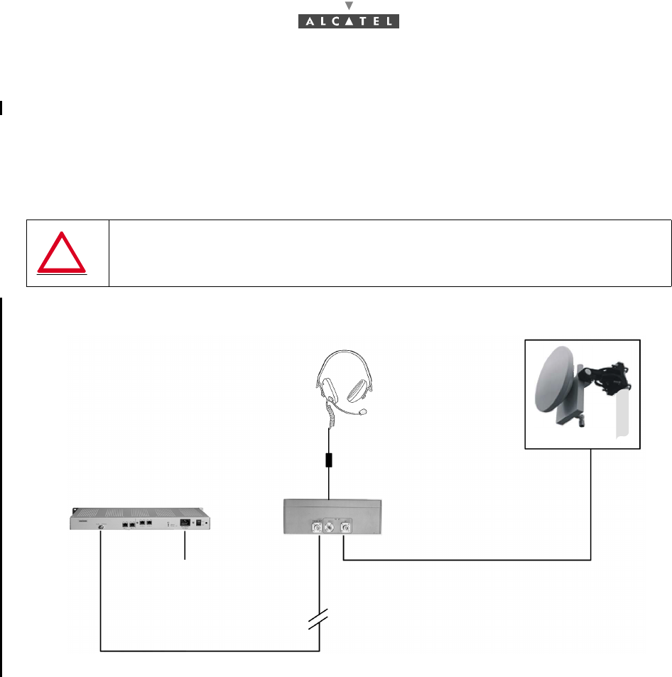
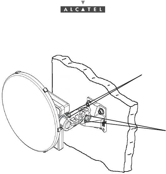
To carry out RT unit antenna alignment, implement the assembly shown in Figure 43 – RT antenna fine
alignment assembly diagram.
Figure 43 – RT antenna fine alignment assembly diagram
WARNING: DO NOT PERFORM SUCH ASSEMBLY IN STORMY CONDITIONS; THE
EQUIPMENT METAL STRUCTURES MAY BE A TARGET FOR LIGHTNING
RT/E-RIT link cable (tool cable)
"Site" coaxial cable
mains 85 - 264 VAC
47 - 63 HZ
NT modem
E-RIT tool
Headset
E-RIT / Headset (tool cable) RT
(link E-RIT/NT)
3CC12423AAAA TQ BJA 01 Issue 01 - March 2001 - Draft 03 65/ 114
78
–Help for using the E-RIT
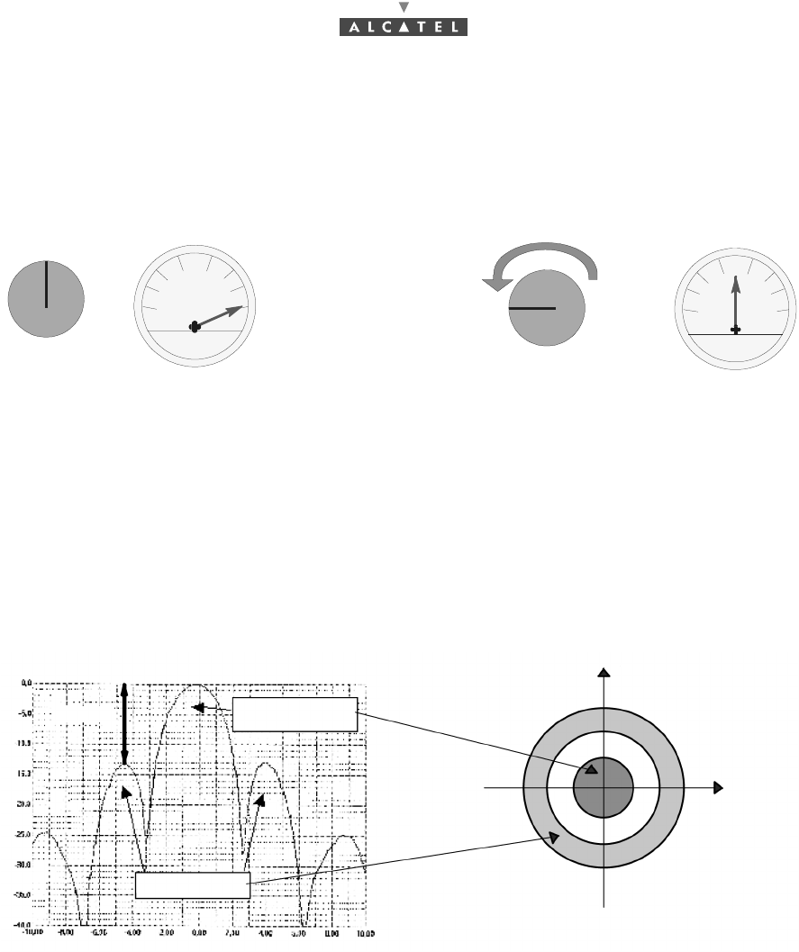
•E-RIT tool received field indicator (represented in Figure 44 – Adjustment procedure using
the E-RIT tool potentiometer): to the maximum received field corresponds a maximum vumeter
pointer deviation; as soon as the pointer reaches its maximum stop, adjust the potentiometer
to set the pointer back to its center position (these adjustments may be renewed).
Figure 44 – Adjustment procedure using the E-RIT tool potentiometer
•audio headset connected to the "service kit" cable: to the minimum received field corresponds
a low frequency audio signal (headset's LF tone); to the maximum received field corresponds
a high frequency audio signal.
The received signal follows the curve below which comprises several maximum points called "lobes":
Figure 45 – Main lobe and side lobes of the received signal
Note: As the side lobes are rather close (4° to 5°) from the main lobe at a rather high level (-15 dB),
searching the maximum received signal must be carried out carefully to make sure that pointing
is effectively carried out considering the main lobe (see § Horizontal and vertical pointings).
Potentiometer
Vumeter Vumeter
Potentiometer
15 dB
side lobes
main lobe
Vertical plane
Lobe cross-section
Horizontal
~±1.5 for every
~±6 to ~-15 dB
3 dB level
deviation
from the main lobe
plane
66/ 114 Issue 01 - March 2001 - Draft 03 3CC12423AAAA TQ BJA 01
78
2. Pointing an integrated antenna
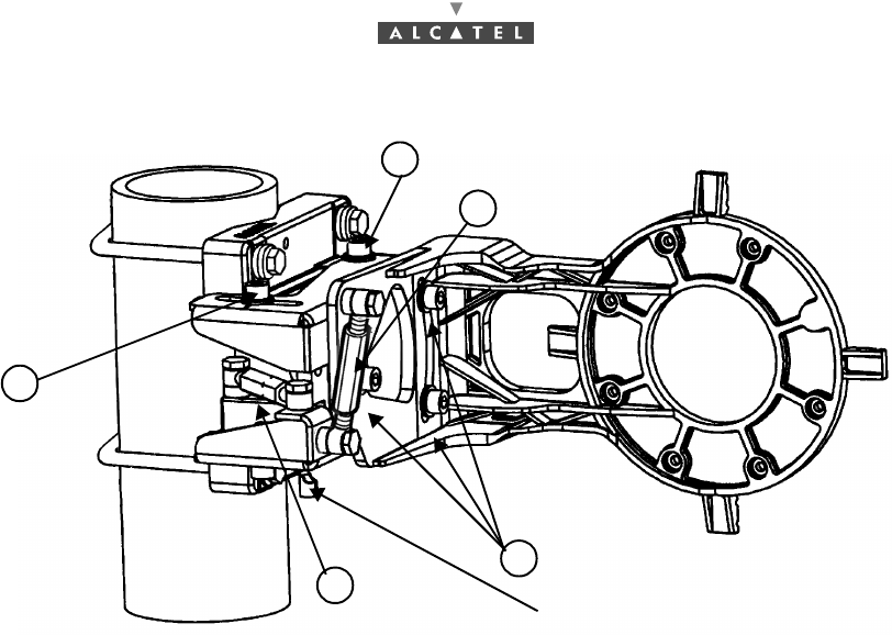
Figure 46 – "azimuth" and "elevation" adjustment screw
–Presets:
•Using the Allen key, slightly untighten the "azimuth" and "elevation" screws so that the RT
can move easily (marks 1 and 2, Figure 46 – "azimuth" and "elevation" adjustment screw).
•Horizontally direct the RT to the Base Station using a compass if necessary.
–Horizontal and vertical pointings:
Using the E-RIT tool and/or the audio headset (see section Help for using the E-RIT § 4.2.3.4 Ali-
gning the RT unit antenna), perform the following adjustments:
•Move the RT radio by performing horizontal scanning, until you find a maximum reception
level.
Note: If no level is detected, check with the compass that the RT correctly points to the base station. In
case of failure check the installation (polarization, connections).
•Carry out alignment with respect to the strongest signal. To do this, either:
•observe the maximum field level on the E-RIT tool indicator shown in Figure 44 – Adjust-
ment procedure using the E-RIT tool potentiometer,
•or, evaluate the maximum field level using the audio headset connected to the service kit
cable,
•Using the Allen key, slightly tighten the "azimuth" screws (mark 1, Figure 46 – "azimuth" and
"elevation" adjustment screw) before performing the vertical pointing, in order to maintain a
maximum azimuth reception and make the two adjustments independent (H and V).
•Provided that a maximum has effectively been detected during the previous pointing, several
cases are possible depending on the maximum position in the reception curve (see Figure 45
– Main lobe and side lobes of the received signal).
1
2
3CC12423AAAA TQ BJA 01 Issue 01 - March 2001 - Draft 03 67/ 114
78
3. Pointing a non integrated antenna
Figure 47 – Pole mounting 1+0 9900UXI102
–Presets:
•Be sure that the three screws ¥ and the four screws ¦ are a bit slackened, just enough to allow
movement of the different parts of the pole mounting. These screws must not be too much slac-
kened, otherwise, the fine-tuning of alignment will be imperfect. Use the 10 mm Allen key.
•Horizontally direct the RT to the Base Station using a compass if necessary.
–Horizontal and vertical pointings:
Using the E-RIT tool and/or the audio headset (see section Help for using the E-RIT § 4.2.3.4 Ali-
gning the RT unit antenna) , perform the following adjustments:
•Move the RT radio by performing horizontal scanning, until you find a maximum reception
level.
Note: If no level is detected, check with the compass that the RT correctly points to the base station. In
case of failure check the installation (polarization, connections).
•Carry out alignment with respect to the strongest signal. To do this, either:
•observe the maximum field level on the E-RIT tool indicator shown in Figure 44 – Adjust-
ment procedure using the E-RIT tool potentiometer,
•or, evaluate the maximum field level using the audio headset connected to the service kit
cable,
•with the azimutal turnbuckle ¨ and the 16 mm flat wrench, fine tune the azimutal setting,
before performing the vertical pointing, in order to maintain a maximum azimut reception
and make the two adjustments independent (H and V),
•with the vertical turnbuckle § and the 16 mm flat wrench, fine tune the elevation setting until
you find a maximum reception level. Be aware that if the elevation angle is higher than +5º
or lower than -5º, it is necessary to remove completely one of the 2 screws fixing the anten-
na support on the azimut support and insert it in the third hole accessible. See Appendix 6
– Installation of the Terminal Station RT unit with a non integrated antenna.
•Provided that a maximum has effectively been detected during the previous pointing, several
cases are possible depending on the maximum position in the reception curve (see Figure 45
– Main lobe and side lobes of the received signal):
Azimutal
Elevation
Grounding connection
3 screws elevation tightening
1
2
4
3
2
4 screws azimutal tightening
turnbuckle
turnbuckle
68/ 114 Issue 01 - March 2001 - Draft 03 3CC12423AAAA TQ BJA 01
78
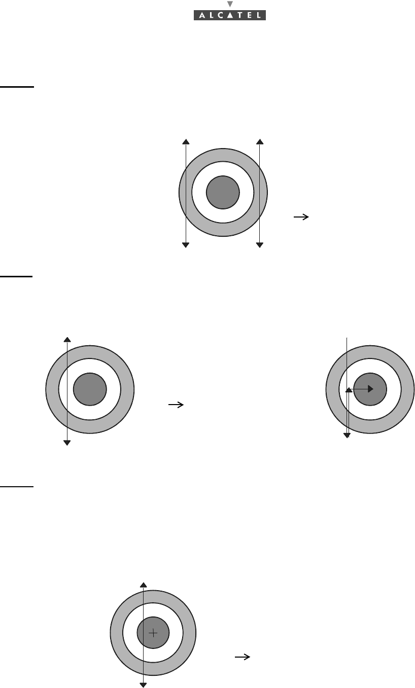
Note: The following cases are treated for the vertical scanning (site), they are also valid for the horizon-
tal scanning (azimuth).
Case 1 (Figure 48 – Vertical scanning: case 1): only one wide maximum is found throughout the
vertical scanning. Thus the RT is aligned within the ± 6° deviation range corresponding to the side lobe.
Then slightly move the RT horizontally (by less than 6°) to the BS.
Perform again vertical scanning.
Figure 48 – Vertical scanning: case 1
Case 2 (Figure 49 – Vertical scanning: case 2): only two remote maxima have been found throughout
vertical scanning.
Then adjust the vertical position so that the reception level is at the minimum between both maxima.
Horizontally move the RT until the main lobe is found, as shown in Figure 49 – Vertical scanning: case
2.
Figure 49 – Vertical scanning: case 2
Case 3 (Figure 50 – Vertical scanning: case 3): three maxima have been found throughout vertical
scanning, including one maximum of higher level (main lobe).
Then move the RT so that it matches the central maximum.
Use the potentiometer to distinguish both maximum types by varying the received signal sensitivity and
thus confirm that the pointing effectively corresponds to the main lobe (maximum of higher level).
Slightly adjust the vertical and horizontal positions until the maximum main lobe level is reached.
RT alignment with the base station is then correct.
Figure 50 – Vertical scanning: case 3
Only one maximum is found:
the received signal curve follows
one of the side lobes
pointing to be continued
The double arrow symbolizes
the vertical scanning
Two maxima are detected:
the received signal curve follows
both side lobes
pointing to be continued
Schematization of the pointing
to be performed
Three maxima are detected:
the received signal curve follows
both side-lobes and the main lobe
pointing to be adjusted to the maximum
of the main lobe (point M)
M
3CC12423AAAA TQ BJA 01 Issue 01 - March 2001 - Draft 03 69/ 114
78
Note: If no maximum is detected throughout vertical scanning, it means that the horizontal reception
maximum is lost, the horizontal position is not located within the ± 6° deviation range.
Then horizontally move the RT to the BS so that a maximum is found and vertically scan again
to find one of the 3 previously described cases.
–End of pointing
Once alignment is completed:
•For an integrated antenna, tighten the "azimuth" screws using the Allen key, then the "eleva-
tion" screws (marks 1 and 2, Figure 46 – "azimuth" and "elevation" adjustment screw).
•For a non integrated antenna, tighten the three screws ¥ and the four screws ¦ (Figure 47 –
Pole mounting 1+0 9900UXI102).
•Make sure the maximum reception signal is always found.
•Completely lock the mechanical assembly preventing the RT radio assembly from misaligning
4. Cabling according to standards
–Remove the tools and cables used for the RT commissioning and adjustment.
–On the Radio side, connect the RT/NT connection cable in accordance with the requirements in-
dicated in § 3.6 Installation of the RT/NT link.
–Screw up the stopper of catch BNO on the radio to allow the sealing of the radio.
Make sure you observe the conditions of case 3 before performing
the following step to complete the pointing
TORQUE VALUE MUST BE 9 TO 10 m.N. USE A TORQUE WRENCH
TORQUE VALUE MUST BE 30 m.N. ± 10 %. USE A TORQUE WRENCH
IMPORTANT NOTE: IT IT MANDATORY TO OBSERVE THE REQUIREMENTS IN
PARAGRAPH (3.6) ENSURING RT/NT CABLE WATERTIGHTNESS
(THERMOSHRINKABLE SLEEVE) AND ATTACHMENT (CLIPS)

70/ 114 Issue 01 - March 2001 - Draft 03 3CC12423AAAA TQ BJA 01
78
4.3 Commissioning the NT
Note: To carry out the following phases of the Terminal Station commissioning, the link Base Station
must be operational and its antenna correctly orientated.
Considerations
–Before commissioning the NT unit, complete the RT unit adjustment procedures.
–No adjustment is required for commissioning the NT.
–To check the voltage at the mains connector terminals, use a measuring instrument (voltmeter).
–For the mains connection, use only the connection cable supplied with the equipment.
–Never use an extension cable for connecting the NT unit to the power source.
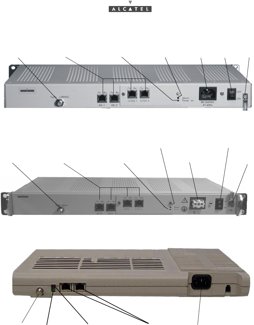
Stages (Figure 51 – The NT unit 220V)
1. Connect the RT/NT connection cable. Use ref. 1 connector.
2. To ground the NT unit in this way, carry out the procedures described in Chapter 3 Installation of the
7390TS Terminal Station. Use the lug and screw hardware supplied with the equipment, ref. 7.
3. Check that the mains socket to which the NT is to be connected supplies voltage compliant with the
equipment characteristics and that it is fitted with an earth.
4. (ref. 5)
•For NCAxxx: connect the NT connection cable to the NT connector and then to the mains.
•For NGAxxx: connect the 48V cable to the HE15-3 connector, then to the 48V arrival.
5. Power-up the NT unit using the On/Off switch (ref. 6); the green "Power on" LED (ref. 3) lights up.
The red "Alarm" LED (ref. 4) lights up (searching for the carrier frequency) then flashes at different
rates according to the current phase:
•slow flashing: automatic scanning over the frequencies,
•fast flashing: frame recovery (authentication by the serial number) once the frequency is
found.
3CC12423AAAA TQ BJA 01 Issue 01 - March 2001 - Draft 03 71/ 114
78
Malfunctions to the installation:
The A7390 is a reliable and easy-to-install system. By following the procedures described in the
documentation, no problems should occur. However, if these procedures have been poorly applied, here
is a list of the possible problems that may arise.
6. Wait for this automatical initialization time of the NT. As soon as the red LED (ref. 4) goes out, the
system can be managed by the BS (calibration of the radio link (output, frequency, time) has been
performed).
Note: The maximum initialization time is in the order of 5 minutes (otherwise see § 5.4 Changing a
faulty NT unit).
Client terminals are connected to the ref. 2 connectors (see § 4.4 Client terminal connections (NT unit)
or § 4.5 Client terminal connections (NT Lite unit)
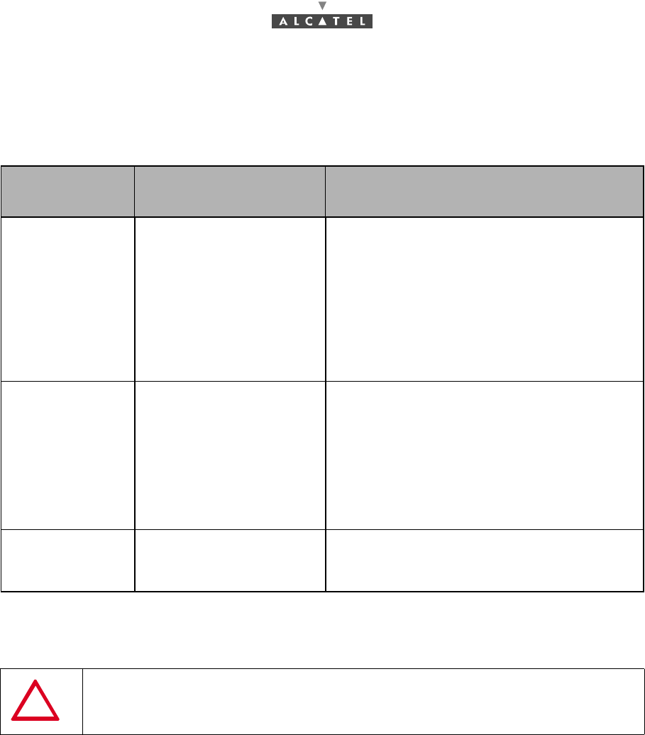
Manifestation of
the problem Possible causes Solution
The red NT LED is
flas-hing slowly. 1 Errored NT declaration.
2 Poor connector contact.
3 Cable damaged or
severed.
4 Alignment problem.
5 Incorrect RT settings.
6 RT breakdown.
7 NT breakdown.
1 Check NT declaration.
2 Check connectors. Secure loo-sely cabled
connectors.
3 Check installation wiring. Change damaged
cables.
4 and 5 Reconfigure and check antenna alignn-
ment (cf. § 4.2.3 Site configuration and adjust-
ment procedures).
6 Replace RT.
The red NT LED is
flas-hing quickly. 1 Bad transmission.
2 Incorrect NT settings. 1 Delete and recreate the managed NT using
the 7390LT.
Check the allocation of the correct NT serial
number.
2 and 3 Reconfigure and check antenna alignn-
ment (cf. § 4.2.3 Site configuration and adjust-
ment procedures).
4 Replace RT.
The red NT LED
rest lit uninterrup-
ted
1 Check the NT supply
voltage
2 NT breakdown.
Try a swith off/switch on, and if the LED remains
red, replace NT.
NEVER DISCONNECT THE NT/RT LINK UNLESS REQUIRED FOR MAINTENANCE
OR INSTALLATION PURPOSES. SUCH INTERVENTION MUST BE CARRIED OUT IN
ACCORDANCE WITH THE PROCEDURE INDICATED IN CHAPTER 5
72/ 114 Issue 01 - March 2001 - Draft 03 3CC12423AAAA TQ BJA 01
78
.
Figure 51 – The NT unit 220V
Figure 52 – The NT unit 48 Vcc
Figure 53 – The NT Lite unit 220 Vcc
NT/RT Link
1
Terminal connexion
2Mains
5Ground
7
ON/OFF
Power on LED
3
Ready on LED
46
NT/RT Link
1Terminal connexion
2DC Input socket
5Ground
7
ON/OFF
6
Power on LED
3
Ready on LED
4
NT/RT Link
1
Terminal connexion
2Mains
5
Power on LED
3Ready on LED
4
3CC12423AAAA TQ BJA 01 Issue 01 - March 2001 - Draft 03 73/ 114
78
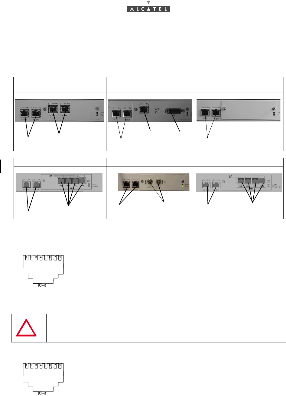
4.4 Client terminal connections (NT unit)
There are ten types of NT units:
4.4.1 Ethernet connector
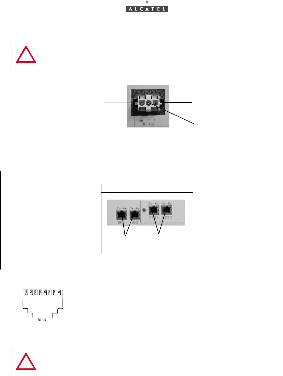
Figure 54 – Affectation of Ethernet access points at NT back
4.4.2 G703 connector (120 ohm E1 and 100 ohm T1 standards)
9900 NCA 001, 9900 NGA 001
and 9900 NCE 001 9900 NCA 002 9900 NCD 001
9900 NCB 001, 9900 NGB 001 9900 NGA 004 9900 NCB 002, 9900 NGB 002
Pin 1: Tx_diff_plus Pin 5: Not connected
Pin 2: Tx_diff_Moins Pin 6: Rx_diff_Moins
Pin 3: Tx_diff_plus Pin 7: Not connected
Pin 4: Not connected Pin 8: Not connected
SHIELDED CABLES MANDATORY
Pin 1: Rx_Ring Pin 5: Tx_Tip
Pin 2: Rx_Tip Pin 6: Not connected or
equiment ground
Pin 3: Not connected or
equipment ground Pin 7: Not connected
Pin 4: Tx_Ring Pin 8: Not connected
2 x Eth 10bT 2x G703:
E1 for NCA001 and NGA001
T1 for NCE001
G703 X21
2 x Eth 10bt 2 x Eth 10bt
2 x Eth 10bT
4 x ISDN/2B1Q 60V 2 x G703
2 x Eth 10bT 4ISDN/4B3T-60V
2 x Eth 10bT
Front view soket
Front view soket
74/ 114 Issue 01 - March 2001 - Draft 03 3CC12423AAAA TQ BJA 01
78
OR
Figure 55 – Affectation of G703 access points at NT back
4.4.3 X21 connector
If the distance between DCE (NT) and DTE is too long, according to V11 norms, you can exchange pin
6 and pin 13 in order to get a phase inversion
.
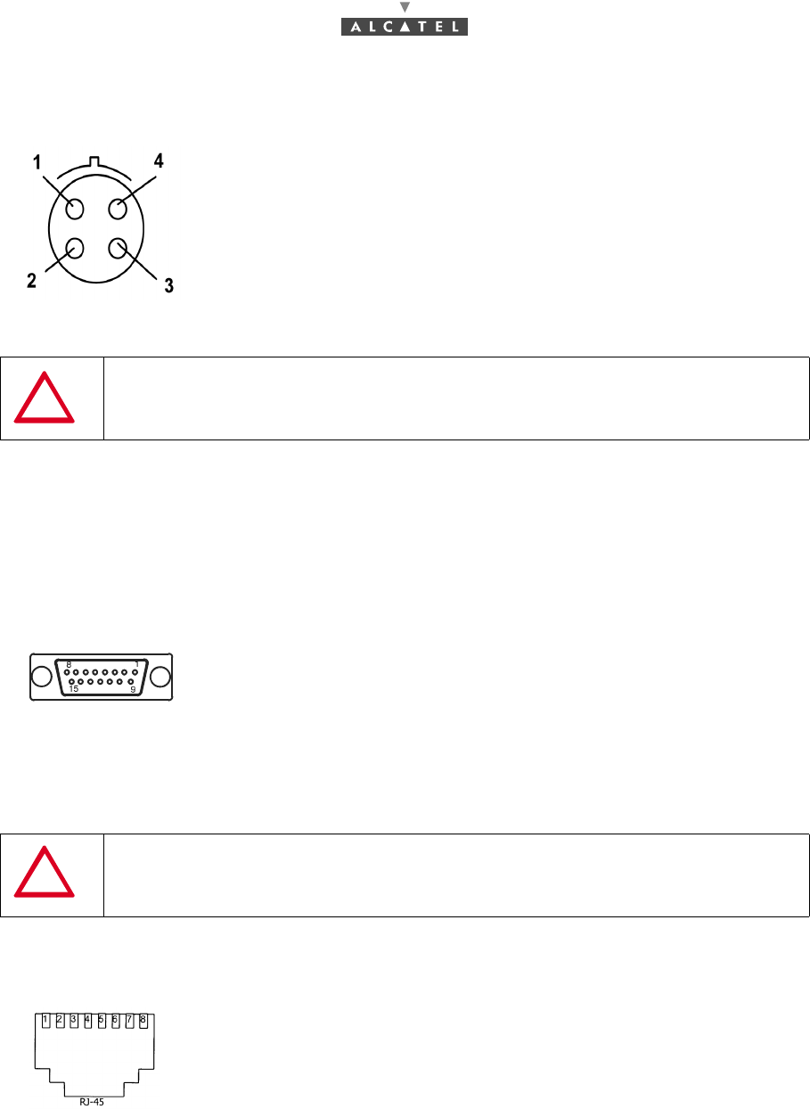
Figure 56 – Affectation of X21 connector access points
4.4.4 ISDN connector (Norm TS 102 - 080)
Figure 57 – Affectation of ISDN access points at NT back
Pin 1: Rx_Ring
Pin 2: Tx_Tip
Pin 3: Rx_Ring
Pin 4: Rx_Tip
SHIELDED CABLES MANDATORY
Pin 1: Screw Pin 6: S_neg Pin 11: R_pos
Pin 2: T_neg Pin 7: B_neg Pin 12: I_pos
Pin 3: C_neg Pin 8: Ground Pin 13: S_pos
Pin 4: R_neg Pin 9: T_pos Pin 14: B_pos
Pin 5: I_neg Pin 10: C_pos Pin 15: Not
connected
SHIELDED CABLES MANDATORY
Pin 4: TIP
Pin 5: RING
LEMO
Female connector
Front view soket
3CC12423AAAA TQ BJA 01 Issue 01 - March 2001 - Draft 03 75/ 114
78
4.4.5 48V connector (HE 15)
Figure 58 – Affectation of 48 V points
4.5 Client terminal connections (NT Lite unit)
There are two types of NT units:
4.5.1 Ethernet connector
Figure 59 – Affectation of Ethernet access points at NT back
SHIELDED CABLES MANDATORY
9900 NCF 001, 9900 NCG 001(*)
Pin 1: Tx_diff_plus Pin 5: Not connected
Pin 2: Tx_diff_Moins Pin 6: Rx_diff_Moins
Pin 3: Tx_diff_plus Pin 7: Not connected
Pin 4: Not connected Pin 8: Not connected
SHIELDED CABLES MANDATORY
Ground 0 V / + 48 V
- 48 V / 0 V
2 x Eth 10bT 2xG703(E1):
1 x Eth 10bT(*) 1xG703 E1 for NCF001
Front view soket