Alcatel Canada 24T07A01D22D 7390 24 GHz Co-Pol RT User Manual NT Manual pages 101 to 114
Alcatel Canada Inc 7390 24 GHz Co-Pol RT NT Manual pages 101 to 114
Contents
NT Manual pages 101 to 114

3CC12423AAAA TQ BJA 01 Issue 01 - March 2001 - Draft 03 101/ 114
104
24-30 GHz-RT with an integrated
antenna of 26 cm 9900RTA001 3CC 11956 ABxx
3CC 12115 ABxx
28/425/B 28 GHz
RT with N connector
RT with F connector
24-30 GHz-RT with an integrated
antenna of 26 cm 9900RTA001 3CC 11956 ACxx
3CC 12115 ACAA
28/425/C 28 GHz
RT with N connector
RT with F connector
24-30 GHz-RT with an integrated
antenna of 26 cm 9900RTA001 3CC 11956 ADxx
3CC 12115 ADxx
28/425/D 28 GHz
RT with N connector
RT with F connector
24-30 GHz-RT with an integrated
antenna of 26 cm 9900RTA001 3CC 10886 ABxx
3CC 11588 ABxx
28/500/B 28 GHz
RT with N connector
RT with F connector
24-30 GHz-RT with an integrated
antenna of 26 cm 9900RTA001 3CC 10886 ACxx
3CC 11588 ACxx
28/500/C 28 GHz
RT with N connector
RT with F connector
24-30 GHz-RT with an integrated
antenna of 26 cm 9900RTA001 3CC 10110 AAxx
3CC 11947 AAxx
28/723/A 28 GHz
RT with N connector
RT with F connector
24-30 GHz-RT with an integrated
antenna of 26 cm 9900RTA001 3CC 10110 ABxx
3CC 11947 ABxx
28/723/B 28 GHz
RT with N connector
RT with F connector
24-30 GHz-RT with an integrated
antenna of 26 cm 9900RTA001 3CC 10883 AAxx
3CC 11946 AAxx
28/1008/A 28 GHz
RT with N connector
RT with F connector
24-30 GHz-RT with an integrated
antenna of 26 cm 9900RTA001 3CC 10883 ACxx
3CC 11946 ACxx
28/1008/C 28 GHz
RT with N connector
RT with F connector
24-30 GHz-RT with an integrated
antenna of 26 cm 9900RTA001 3CC 10883 ADxx
3CC 11946 ADxx
28/1008/D 28 GHz
RT with N connector
RT with F connector
24-30 GHz-RT with adaptator for
60 cm antenna 9900RTC001
3CC 11541 AAxx
3CC 12507 AAxx
25/1008/A
+ adaptator
RT with N connector
RT with F connector
24-30 GHz-RT with adaptator for
60 cm antenna 9900RTC001
3CC 11542 AAxx
3CC 12507 ABxx
25/1008/B
+ adaptator
RT with N connector
RT with F connector
24-30 GHz-RT with adaptator for
60 cm antenna 9900RTC001
3CC 11543 AAxx
3CC 12507 ACxx
25/1008/C
+ adaptator
RT with N connector
RT with F connector
Installation item Commercial
code Industrial code Comments

102/ 114 Issue 01 - March 2001 - Draft 03 3CC12423AAAA TQ BJA 01
104
24-30 GHz-RT with adaptator for
60 cm antenna 9900RTC001
3CC 11544 AAxx
3CC 12507 ADxx
25/1008/D
+ adaptator
RT with N connector
RT with F connector
24-30 GHz-RT with adaptator for
60 cm antenna 9900RTC001
3CC 11545 AAxx
3CC 12508 AAxx
25/1480/A
+ adaptator
RT with N connector
RT with F connector
24-30 GHz-RT with adaptator for
60 cm antenna 9900RTC001
3CC 11921 AAxx
3CC 12508 ABxx
25/1480/B
+ adaptator
RT with N connector
RT with F connector
24-30 GHz-RT with adaptator for
60 cm antenna 9900RTC001
3CC 11546 AAxx
3CC 12509 AAxx
26/855/A
+ adaptator
RT with N connector
RT with F connector
24-30 GHz-RT with adaptator for
60 cm antenna 9900RTC001
3CC 11547 AAxx
3CC 12509 ABxx
26/855/B
+ adaptator
RT with N connector
RT with F connector
24-30 GHz-RT with adaptator for
60 cm antenna 9900RTC001
3CC 11534 AAxx
3CC 12506 ABxx
28/425/B
+ adaptator
RT with N connector
RT with F connector
24-30 GHz-RT with adaptator for
60 cm antenna 9900RTC001
3CC 11535 AAxx
3CC 12505 AAxx
28/500/A
+ adaptator
RT with N connector
RT with F connector
24-30 GHz-RT with adaptator for
60 cm antenna 9900RTC001
3CC 11535 AAxx
3CC 12505 ABxx
28/500/B
+ adaptator
RT with N connector
RT with F connector
24-30 GHz-RT with adaptator for
60 cm antenna 9900RTC001
3CC 11536 AAxx
3CC 12505 ACxx
28/500/C
+ adaptator
RT with N connector
RT with F connector
24-30 GHz-RT with adaptator for
60 cm antenna 9900RTC001
3CC 11537 AAxx
3CC 12500 AAxx
28/723/A
+ adaptator
RT with N connector
RT with F connector
Installation item Commercial
code Industrial code Comments

3CC12423AAAA TQ BJA 01 Issue 01 - March 2001 - Draft 03 103/ 114
104
24-30 GHz-RT with adaptator for
60 cm antenna 9900RTC001
3CC 11538 AAxx
3CC 12500 ABxx
28/723/B
+ adaptator
RT with N connector
RT with F connector
24-30 GHz-RT with adaptator for
60 cm antenna 9900RTC001
3CC 11540 AAxx
3CC 12504 AAxx
28/1008/A
+ adaptator
RT with N connector
RT with F connector
Version CO-POL
RT installation tools
Installation tools
(E-RIT+cables +soft) 9900YTA001 3CC 10784 AAxx
Splitter 8V 9900XTC003 3CC 11876 AAxx
Installation item Commercial
code Industrial code Comments

104/ 114 Issue 01 - March 2001 - Draft 03 3CC12423AAAA TQ BJA 01
104
PAGE INTENTIONALLY LEFT BLANK
3CC12423AAAA TQ BJA 01 Issue 01 - March 2001 - Draft 03 105/ 114
112
Appendix 6 – Installation of the Terminal Station RT
unit with a non integrated antenna
The installation of the RT unit should satisfy the following criteria:
–unimpeded direct line of sight between RT unit and RBS (Base Station),
–perfect mechanical rigidity,
–enabling precise antenna alignment.
The 7390RT is designed for outdoor installation without any particular protection. However, the following
recommendations must be respected:
–do not install equipment below bird nesting areas,
–do not attach equipment to a surface prone to vibrations (machinery, lift housing, air conditioning,
etc.),
–do not attach equipment to chimneys which give off fat deposits, dust and other aerosols which
are liable to come to rest on the equipment,
–do not install equipment in proximity of sources of heat,
–do not place the equipment in proximity to corrosive gas outputs,
–do not place the equipment below roof run-offs not equipped with guttering (high risk of microwave
short-circuit),
–do not install at man-height to prevent human collisions against the antenna. This could cut the
radio link with the central station.
The antenna is screwed on the pole mounting 1+0 (9900UXI102). The RT is mounted with quick latches.
Overall antenna steer (with turnbuckles set to the "maximum") is:
•Azimuth: 360 degrees around the pipe.
The steer obtained by the turnbuckles is:
•Elevation: ± 25 degrees,
•Azimuth: ± 10 degrees.
To avoid obstacles (wall too close, etc), you can fix the pole mounting on any side of the pipe.
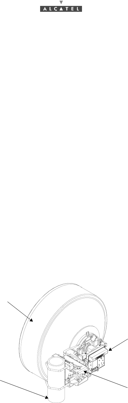
Figure 63 – Typical installation
RT
Pole mounting
600 mm antenna
Pipe
106/ 114 Issue 01 - March 2001 - Draft 03 3CC12423AAAA TQ BJA 01
112
The pole mounting is supplied complete, mechanically assembled, with screw fastenings kit and ground
terminals included in a plastic bag inside the casting.
The mechanical system is mounted on a pipe with a diameter of 114 mm. The pole/tube selected should
be sufficiently rigid to prevent antenna misaligment and resist vibrations.
The weights of the radio subsystem components are:
•Pole mounting 1+0 (9900UXI102): 4.7 Kg
•RT unit 1.5 Kg
•600 mm antenna: 12 Kg
•Overall weight: 18.2 Kg
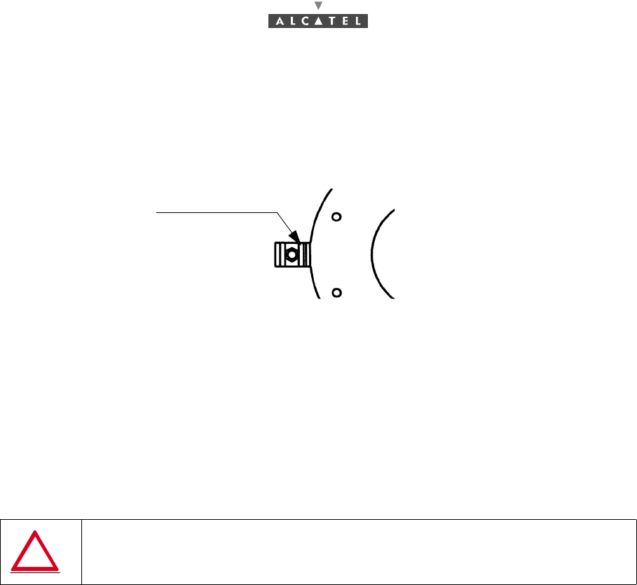
A.6.1 – Choosing antenna polarization
The antennas are normally tuned for vertical polarization.
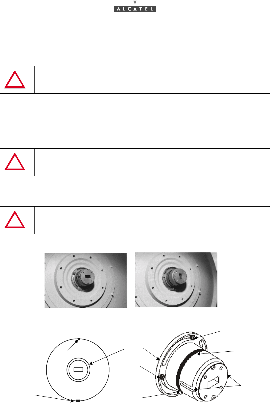
Figure 64 – Antenna nose end view
CAUTION: verticality of ± 1 degree is required for polarization
CAUTION: The pole mounting 1+0 (9900UXI102) is not designed
to be fixed directly to the wall
CAUTION: Use the same polarization on Terminal Station and Base Station
Vertical polarization Horizontal polarization
Socket cap screw
"Antenna nose"
Gasket
Drain orifice
Nose
Socket cap
TOP marker
Fixing
TOP
TOP
vertical polarization
Antenna nose end view
slots
screw
screw
3CC12423AAAA TQ BJA 01 Issue 01 - March 2001 - Draft 03 107/ 114
112
To change the polarization:
–slacken the three socket cap screws,
–turn the nose through 90 degrees,
–tighten the screws again.
A.6.2 – Installing the configuration with pole mounting 1+0
(9900UXI102)
The installation takes place in 4 steps:
–Installing the antenna on the pole mounting (§ A.6.2.1 – Installing the antenna on the pole moun-
ting),
–Installing the RT unit (§ A.6.2.2 – Installing the RT unit),
–Installing on the pipe (§ A.6.2.3 – Installing on the pipe),
–Coarse alignment of the antenna, (§ A.6.2.4 – Coarse alignment of the antenna).
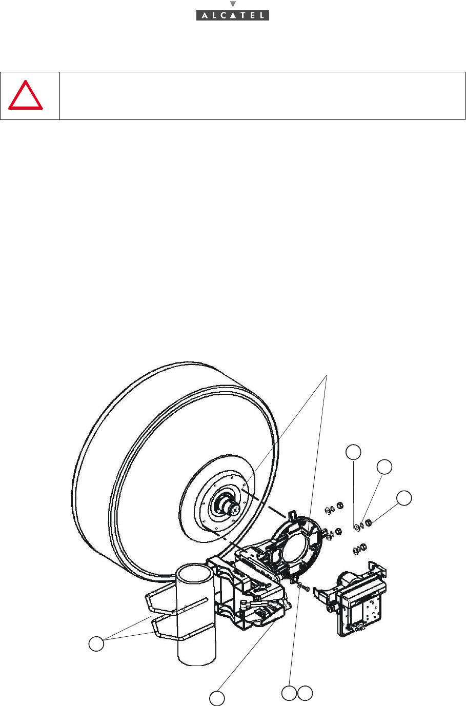
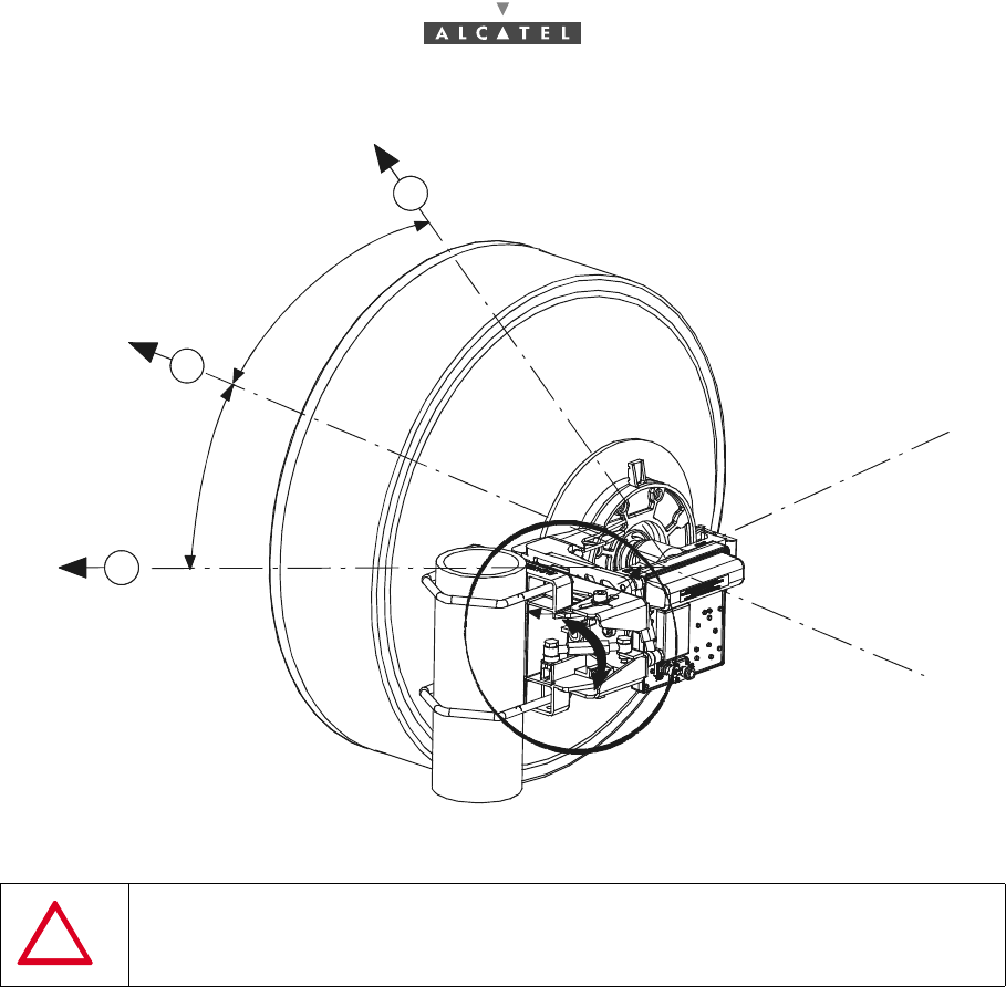
Figure 65 – 9900UXI102 configuration
CAUTION: The seal should be coated with silicon grease before fitting.
The grease is provided with the antenna.
Centeringpin
Flat washer
Grower washer
Nut
Brackets
Casting M6 x (7) screw and
5
6
3
4
27
1"Onduflex" washer
108/ 114 Issue 01 - March 2001 - Draft 03 3CC12423AAAA TQ BJA 01
112
A.6.2.1 – Installing the antenna on the pole mounting
1. Position the antenna verticaly (nose horizontal), with the drain hole in the bottom part and free of
obstacles.
2. Position the pole mounting centering pin in hole on the antenna.
3. Insert the M6 screws (7 in all ) ¦ and "Onduflex" springy crinkle washers «, tighten and secure the
screws (these screws can be found in a plastic bag located inside the casting ¥).
A.6.2.2 – Installing the RT unit
This installation can be done only during commissioning.
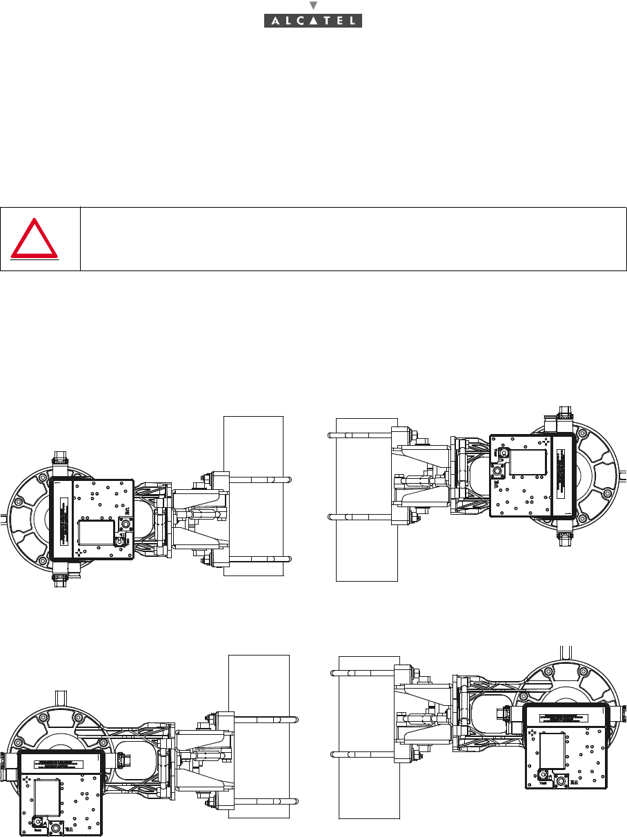
Two choices per polarization are possible:
Vertical polarization
Horizontal polarization
Figure 66 – Installing the RT unit
CAUTION: Take care not to damage the O-Ring on the nose of the antenna
connection. If the RT is not to be mounted immediatly after the pole mounting of
the antenna, protect the connection nose (from water, dirt and impact).
3CC12423AAAA TQ BJA 01 Issue 01 - March 2001 - Draft 03 109/ 114
112
–remove the plastic protection on the "nose" of the unit,
–offer up the two bosses on the "nose" of the unit to the two slots in the "nose" of the antenna,
–hold onto the RT unit, and
–lock the two catches in the position shown below.
Figure 67 – Position of catch
REMINDER:
–The RT unit/antenna assembly requires no additional seal on the flanges; the two ends are
smooth. Sealing is provided by the O-ring seal around the male "noses".
–When the RT unit is fitted, the polarization of both antenna and RT unit can be ascertained, looking
the rear of the RT unit.
If the letter "H" can be read naturally, polarisation is horizontal.
If the letter "V" can be read naturally, polarisation is vertical.
A.6.2.3 – Installing on the pipe
Note:
–Be aware that azimutal coarse alignment of antenna is done at this phase.
–To avoid obstacles (wall too close, etc.), you can fix the pole mounting on any side of the pipe (see
Figure 66 – Installing the RT unit).
–Check the polarization indicator to check correct polarization.
A.6.2.4 – Coarse alignment of the antenna
–Azimutal coarse alignment has to be carried out when installing the pole mounting.
–Prepoint antenna visually and/or using a compass and a map.
–Orientate the pole mounting so that the antenna is pointed towards the Base Station antenna.
CAUTION: Once the RT unit is fitted on the pole mounting, never handle the
assembly by the radio but by the pole mounting.
Position of catch
110/ 114 Issue 01 - March 2001 - Draft 03 3CC12423AAAA TQ BJA 01
112
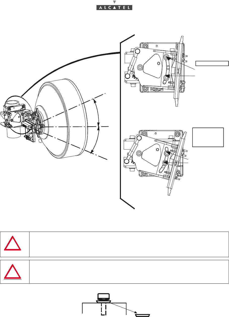
Figure 68 – "Azimutal " alignment of antenna
Elevation alignment is performed only with the elevation turnbuckles. If the elevation angle is higher than
(+ 5°) or lower than (- 5°), it is necessary to:
–remove completely one of the 2 screws fixing the antenna support on the azimut support and,
–insert it in the third hole accessible.
CAUTION: The bracket nuts must be fastened to torque of 3 mdaN, ± 10%. The
bracket must be clean and without grease, except on the threads.
10°
1
2
3
To Base Station antenna
10°
3CC12423AAAA TQ BJA 01 Issue 01 - March 2001 - Draft 03 111/ 114
112
Figure 69 – Elevation coarse alignment of antenna
CAUTION: In either case, the support must be fixed with 3 screws, 2 put in the
window and 1 corresponding to its axis of rotation.
All screws must be tightened and secured only after fine
tune alignment of the antenna
CAUTION: Take care to put the 2 screws in the window with the flat washers
positioned as shown in the figure below.
If: - 5 < α < 5
Put the screws in
the two external
holes.
If: α > 5
or α < - 5
Put the screws
in the 2 holes
visible through
the window, i.e.
the middle and
the external hole.
α = 25°
α = 25°
112/ 114 Issue 01 - March 2001 - Draft 03 3CC12423AAAA TQ BJA 01
112
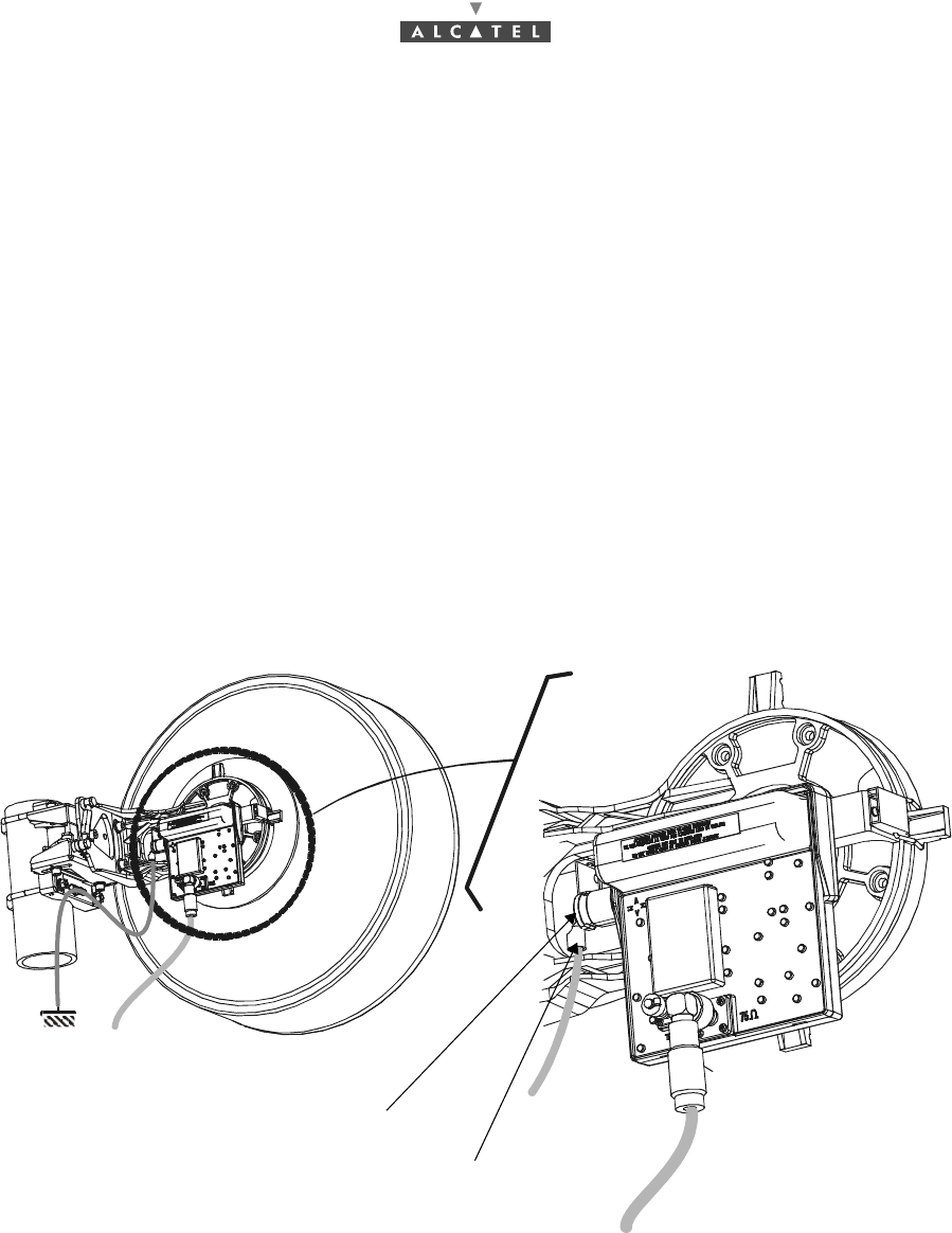
A.6.3 – Grounding the RT unit
Considerations
–It is not necessary to establish special grounding connection for the RT casing. However the RT
unit can be grounded.
–On the RT unit, the ground terminal is in the form of a tapped hole (see Figure 70 – Grounding the
RT unit).
–The RT unit can be grounded using the grounding lug and screw hardware supplied with the equi-
pment.
–On the pole mounting, the ground terminal comprises a screw, two washers and two nuts which
fix the two crimp terminals. It must be installed at the bottom of the pole mounting.
Steps
1. Crimp lugs (ref.: 16-6 CT) on to the grounding cables (16 mm 2 minimum cross-section).
2. Screw the cable lug into the tapped hole of the RT. Use an M6 screw and onduflex washers.
3. On the pole mounting side, put the 2 lugs and the washers on to the grounding screw and tighten
the nut (nut, lugs and washers are supplied with the pole mounting). Use a 10 mm flat wrench.
Figure 70 – Grounding the RT unit
Note: Position of the grounding screw may differ according to mechanical variants beeing either close
to the 75 ohm connector or on the side as shown here.
grounding screw
cable lug

3CC12423AAAA TQ BJA 01 Issue 01 - March 2001 - Draft 03 113/ 114
114
Appendix 7 – List of abbreviations
MNEMONIC ENGLISH MNEMONIC ENGLISH
AAL ATM Adaptation Layer FAS Frame Alignment Signal
AIS Alarm Indication Signal FEC Forward Error Correction
AL Alarm HDB3 High Density Binary 3 code
(3rd order)
AMD ATM Modulator Demodulator IBS Intermediate frequency Base Station
ANT ATM Network Termination ICS Identifier Change Status
ASAP Alarm Severity Assignment Profile I2C or IIC Inter Integrated Circuit
ATM Asynchronous Transfer Mode ID IDentifier
AT Attend alarm on LT IEC International Electrotechnical
Commission
AVC Attribute Value Change IM Information Model
BER Bit Error Rate IP Internet Protocol
BNC Bayonet-locking Connector ISDN Integrated Services Digital Network
BS Base Station ITU International Telecommunication
Union
CBR Constant Bite Rate LAIS Line Alarm Indication Signal
CCIR International radio consultative
comitee LAN Local Area Network
CEPT Conference of European Post and
Telecommunications administrations LED Light Emitting Diode
CPL Coupler LMDS Local Multipoint Distribution Service
CRC Cyclic Redundancy Check LMFA Loss of MultiFrame Alignment
DBS Digital Base Station LOF Loss Of Frame
EMC ElectroMagnetic Compatibility LOP Loss Of Pointer
EPROM Electronically Programmable
Read-Only Memory LOPC Loss Of Polling Cell
ETSI European Telecommunications
Standards Institute LORF Loss Of Radio Frame
ETH Ethernet LOS Loss Of Signal

114/ 114 Issue 01 - March 2001 - Draft 03 3CC12423AAAA TQ BJA 01
114
END OF DOCUMENT
MNEMONIC ENGLISH MNEMONIC ENGLISH
LRDI Line Remote Defect Indicator QAM Quadrature amplitude Modulation
LT Local Terminal RAI Remote Alarm Indicator
MAC Medium Access Control RBS Radio of Base Station
Mbps Mega Bit Per Second RDI Remote Defect Indication
MIB Management Information Base REI Remote Error Indication
MMI Man Machine Interface RF Radio Frequency
MSC Message Sequence Chart RIT Radio Installation Tool
MUX Multiplexer RT Radio Terminal
NE Network Element SC State Change
NFS Network File System SDH Synchonous Digital Hierarchy
NIT Network Installation Tool SMD Surface Mounted Device
NRZ Non return to zero SNMP Simple Network Management
Protocol
NT Network Terminal SNTP Simple Network Time Protocol
OC Object Creation STP Shielded Twisted Pair
OD Object Deletion TAC Technical Assistance Center
OOF Out Of Frame TCP Transmission Control Protocol
OS Operation System TDM Time Division Multiplex
PAIS Path Alarm Indication Signal TE Transaction End
PC Personal Computer TNT TDM Network Termination
PCR Peak Cell Rate TS Terminal Station
PDH Plesiochronous Digital Hierarchy UNI User Network Interface
PLL Phase Locked Loop VPI Virtual Path Identifier
PSU Power Supply Unit VCI Virtual Channel Identifier
PVC Permanent Virtual Circuit WAN Wide Area Network