Alcatel Canada 24T07A01D22D 7390 24 GHz Co-Pol RT User Manual NT Manual pages 76 to 100
Alcatel Canada Inc 7390 24 GHz Co-Pol RT NT Manual pages 76 to 100
Contents
NT Manual pages 76 to 100
76/ 114 Issue 01 - March 2001 - Draft 03 3CC12423AAAA TQ BJA 01
78
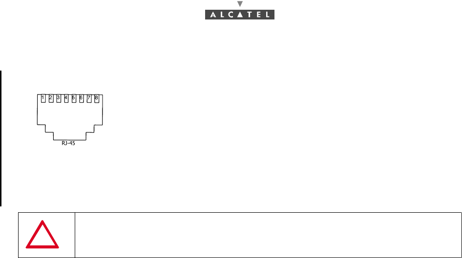
4.5.2 G703 connector (120 ohm E1 and 100 ohm T1 standards)
Figure 60 – Affectation of G703 access points at NT back
4.6 Initiating services
Once RT and NT are installed and in operational status, service initiation requires a further step: the
Base Station operator must activate the cross-connections (see User Manual 3CC 12424 Axxx Base
Station § Client Services and § 6.2 Implementation of client services of the present document).
4.7 Filling in the installation sheet
The installation sheet (Appendix 1 – 7390 TS installation sheet) is initially issued by Radio Planning. It
contains all the data needed by the installer for successful programming of the RT.
The installer must complete this sheet by supplying the requested information, in particular the serial
numbers of the installed equipment, then submit it to the supervisor. The information in the sheet
ensures the traceability of the customer installation equipment, to facilitate subsequent interventions.
The sheet should be signed by the client and the installer. It allows with the customer, the effective
commissionings to be validated.
The sheet consists of three parts:
–7390 RT installation sheet,
–7390 NT installation sheet
–7390 RT/NT connections sheet.
4.7.1 7390 RT installation sheet
This part contains all the information necessary for the configuration. The installer must have this
information to configure the radio part (see 4.2.3.1 Configuration setting of the 7390RT parameters).
For each parameter to be entered according to the Radio Planning, the installer must if appropriate
indicate the real input value if this differs from the value on the sheet. He must also provide the following
information: site and operator co-ordinates.
Pin 1: Rx_Ring Pin 5: Tx_Tip
Pin 2: Rx_Tip Pin 6: Not connected or
equiment ground
Pin 3: Not connected or
equipment ground Pin 7: Not connected
Pin 4: Tx_Ring Pin 8: Not connected
SHIELDED CABLES MANDATORY
Front view soket

3CC12423AAAA TQ BJA 01 Issue 01 - March 2001 - Draft 03 77/ 114
78
4.7.2 NT installation sheet
This sheet is to be completed for each NT in the installation, by filling in the requested information.
4.7.3 RT/NT wiring sheet
The installer must fill in, in this part, all the information relating to the wiring and to the equipment used
for carrying out the assembly.
In addition, a wiring diagram is to be drawn up.

78/ 114 Issue 01 - March 2001 - Draft 03 3CC12423AAAA TQ BJA 01
78
PAGE INTENTIONALLY LEFT BLANK

3CC12423AAAA TQ BJA 01 Issue 01 - March 2001 - Draft 03 79/ 114
80
5 Operation and maintenance
5.1 7390 system supervision
The system operator receives the alarms sent by the network equipment. With the aid of the the 7390LT
software applications, the operator can view and analyze the alarms and trigger the appropriate
operations (see specific procedures below).
On detection of a fault, the operator analyzes alarms and starts the suitable maintenance actions.
5.2 Preventive maintenance
This maintenance is carried out, either during a corrective maintenance inspection, or during a periodic
inspection, on all station equipment. It consists in inspecting the units and their interconnections
(connectors, cables, sockets, etc.) and ensuring that the environment of the Indoor Units (NTs and RTs)
complies with installation requirements (see section 3). It is essential to check connectors and splitters
state with earthing.
In case of doubt, the suspect parts should be checked, taking all precautions to avoid interrupting link
data transmission.
5.3 Corrective maintenance
Corrective maintenance is carried out with the use of the programs of the 7390 LT software.
To use the alarms refer to section "Alarms" of the Base Station User Manual, ref.: 3CC12424Axxx.
5.4 Changing a faulty NT unit
Make sure that the network manager has deleted the NT to be replaced beforehand and declared the
new one, using the 7390 LT software (see the Base Station User Manual, Ref.: 3CC12424 Axxx).
Stages
1. Turn off NT unit power.
2. Disconnect the main cables connecting the NT unit to the power source.
3. Disconnect all cables connected to the NT unit to be changed.
4. Change NT unit after checking that the characteristics coincide (number of inputs, impedance, etc.).
5. Reconnect NT unit cables.
6. Connect the NT power cable to the main supply.
7. Power up NT unit.
8. Wait for "Power on" LED to light up.
9. Wait for flashing of "Alarm" LED. The NT unit is in operation once the LED is extinguished.
DO NOT OPEN THE EQUIPMENT UNDER ANY CIRCUMSTANCE
80/ 114 Issue 01 - March 2001 - Draft 03 3CC12423AAAA TQ BJA 01
80
10. Make NT replace operation in the 7390 LT software application (see section NT replace of the Base
Station User Manual, Ref.: 3CC12424 Axxx)
11. Check the absence of alarms in the 7390 LT software application (see section Alarms of the Base
Station User Manual, Ref.: 3CC12424 Axxx).
12. Update the station installation sheet (Appendix 1 – 7390 TS installation sheet).
5.5 Changing a faulty RT unit
Stages
1. Turn off the NT power supply.
2. Disconnect the mains cable connecting the NT unit to the power source.
3. Disconnect the RT/NT connection cable.
4. Change RT after checking on the label that mnemonics are identicals to the previous one.
5. Install again the RT and carry out antenna alignment. For this, refer to sections 3 and 4.
6. Reconnect the RT/NT connection cable.
7. Connect the NT to the mains supply.
8. Power up the NT.
9. Wait between 2 and 5 minutes. Reconfiguration is automatic.
10. Check the absence of alarms in the 7390 LT software application (see section "Alarms" of the Base
Station User Manual, Ref.: 3CC12424 Axxx).
11. Update the station installation sheet (Appendix 1 – 7390 TS installation sheet).
3CC12423AAAA TQ BJA 01 Issue 01 - March 2001 - Draft 03 81/ 114
84
6 Changes of configuration
The changes to the transmission network may require changes to the equipment configurations in order
to meet new requirements. The A7390 equipment is likely to satisfy these changes either by modifying
just the equipment software configuration or by physically modifying the equipment and its configuration.
These changes may involve either changes of configuration using the 7390 LT software, or changes of
configuration with physical intervention on the equipment.
The possible changes using the 7390 LT software only are:
–declaration/removal/reset of an NT terminal (cf. § 6.1 Declaration, deletion, reset of an NT),
–implementation of client services (cf.§ 6.2 Implementation of client services).
The possible changes with physical intervention are:
–addition/removal of an NT unit (cf. § 6.1 Declaration, deletion, reset of an NT),
–changing an NT unit (cf. § 5.4 Changing a faulty NT unit),
–changing an RT unit (cf. § 6.3 Changing an RT),
–addition of an NT to a cluster (cf. § 6.4 Adding an NT to a cluster),
–affectation of an NT unit to another BS (cf. § 6.5 Affectation of an NT to another BS).
6.1 Declaration, deletion, reset of an NT
To add a new NT :
–update the "Installation information" sheet required for station installation (refer to Appendix 1 –
7390 TS installation sheet),
–carry out installation (refer to Chapter 3 Installation of the 7390TS Terminal Station) and commis-
sioning (refer to Chapter 4 Commissioning the 7390 TS Terminal Station) of the NT,
–to declare the new NT terminal, execute the commands indicated in section Declaring a new NT
of the Base Station User Manual (ref. 3CC12424Axxx).
To delete a NT from the network:
–update the "Installation information" sheet required for station installation (refer to Appendix 1 –
7390 TS installation sheet),
–execute the commands indicated in section NT deletion of the Base Station User Manual (ref.
3CC12424Axxx),
–turn off power to unit using ON/OFF switch (reference 6 of Figure 51 – The NT unit 220V).
To reset a NT :
–execute the commands indicated in section NT reset of the Base Station User Manual (ref.
3CC12424Axxx).
–if necessary, update the "Installation information" sheet (refer to Appendix 1 – 7390 TS installation
sheet).
The supervisor must be informed of any configuration changes

82/ 114 Issue 01 - March 2001 - Draft 03 3CC12423AAAA TQ BJA 01
84
To replace a NT :
–update the "Installation information" sheet required for station installation (refer to Appendix 1 –
7390 TS installation sheet),
–carry out installation (refer to Chapter 3 Installation of the 7390TS Terminal Station) and commis-
sioning (refer to Chapter 4 Commissioning the 7390 TS Terminal Station) of the NT,
–make NT replace operation that changes serial number from old NT to new NT, execute the com-
mands indicated in section NT replace of the Base Station User Manual (ref. 3CC12424Axxx).
6.2 Implementation of client services
To implement client services :
–execute the commands indicated in section Client services of the Base Station User Manual (ref.
3CC12424Axxx),
Note: The system benefits from E1 or IP links. For each case, use the specific procedure.
–if necessary, update the "Installation information" sheet (refer to Appendix 1 – 7390 TS installation
sheet).
6.3 Changing an RT
When changing the RT, as needs to be done in the event of a change to the frequency band on the
Base Station, it is necessary to reinitialise the radio part configuration and in case of an integrated
antenna to carry out antenna alignment (tracking).
To change the RT:
–turn off the mains supply to the NT,
–disconnect the mains cable,
–disconnect the RT/NT link cable,
–for an integrated antenna, carry out installation of the RT unit and tracking of the Terminal Station
antenna (for this, refer to Chapter 3 Installation of the 7390TS Terminal Station).
–restart the Terminal Station. For this, refer to Chapter 4 Commissioning the 7390 TS Terminal Sta-
tion.
–reconfigure the system according to the procedures in Chapter 4 Commissioning the 7390 TS Ter-
minal Station.
For system initialization and retrofit, refer to section NT Supervision of the Base Station User Manual
(ref. 3CC12424Axxx).

3CC12423AAAA TQ BJA 01 Issue 01 - March 2001 - Draft 03 83/ 114
84
6.4 Adding an NT to a cluster
6.4.1 Case of a pre-wired installation
In the case of a pre-wired installation, for which an extension has been envisaged, the cables are already
pulled, the distribution frames and repeaters are already in place and there are load modules filling the
free NT locations.
To add an NT to a cluster:
–remove the load module,
–connect the NT in place of the load module,
–follow the procedure for adding an NT described in § 6.1 Declaration, deletion, reset of an NT.
Note: There is no service interruption and, furthermore, it is not necessary to reconfigure the radio
parameters of the RT.
6.4.2 Case of a non-pre-wired installation
Where extension has not been envisaged, the repeaters and distribution frames must be wired, leading
to an interruption of services. Once wiring has been carried out:
–follow the procedure for adding an NT described in § 6.1 Declaration, deletion, reset of an NT,
–reconfigure the RT radio parameters as described in § 4.2.3 Site configuration and adjustment
procedures.
Note: You are recommended, with a view to possible future Multi-NT use, to wire as for Multi-NT on first
installation. This means that it will not be necessary to reset the RT, so avoiding the interruption
of services.
6.5 Affectation of an NT to another BS
To change the Base Station on a Terminal Station:
–delete the NT in the BS with the 7390 LT software beforehand (cf. § 6.1 Declaration, deletion, reset
of an NT),
–declare the NT in the new BS with the 7390 LT software,
–turn off the mains supply to the NT unit,
–carry out tracking of the Terminal Station antenna. For this, refer to Chapter 3 Installation of the
7390TS Terminal Station.
–restart the Terminal Station. For this, refer to Chapter 4 Commissioning the 7390 TS Terminal Sta-
tion.
–reconfigure the system according to the procedures in Chapter 4 Commissioning the 7390 TS Ter-
minal Station.
For system initialization and retrofit, refer to section NT supervision of the Base Station User Manual (ref.
3CC12424Axxx).

84/ 114 Issue 01 - March 2001 - Draft 03 3CC12423AAAA TQ BJA 01
84
PAGE INTENTIONALLY LEFT BLANK

3CC12423AAAA TQ BJA 01 Issue 01 - March 2001 - Draft 03 85/ 114
90
Appendix 1 – 7390 TS installation sheet
A.1.1 – 7390 RT INSTALLATION SHEET
General information
Radio planning parameters
Name ................................................................... Operator
Address No ............................................................
Street .......................................................
Bld ..... Stair .............
Floor ....................................................
Town ................. Country .................
Installation parameters
to be entered (Radio
planning instructions)
Installation
parameters entered
(OK or new values)
Site identification
Name of the corresponding Base Station
Sector number (1, 2, 3, 4, etc.)
Distance between BS and TS
Altitude difference
Climatic zone (A, B, etc.)
Availability
RBS antenna type (dBi)
RBS antenna tilt
RBS power out
RT antenna type (dBi)
Polarization (H or V)
Frequency band (GHz)
Frequency down link
Frequency up link
Bandwidth
Duplex deviation (MHz)
Sub-band (A,.B, etc.)

86/ 114 Issue 01 - March 2001 - Draft 03 3CC12423AAAA TQ BJA 01
90
7390 RT INSTALLATION SHEET (continuation)
Designation
Version
Reference (3CC...)
ICS (01,02, etc.)
Serial number
Reception level (dBm)
Installation type (rooftop, tower, mast)
Mecanical support References
Radio installation height / ground
Obstacle (type, distance,...)
Installer: Costumer:
Date:
Name:
Visa:
3CC12423AAAA TQ BJA 01 Issue 01 - March 2001 - Draft 03 87/ 114
90
A.1.2 – 7390 NT INSTALLATION SHEET
Name ................................................................... Operator
Address No
..................................................................
Street .......................................................
Bld ..... Stair .............
Floor .......................................................
Town ................ Country .................
Designation NT
Type
Reference (3CC...)
ICS (01,02, ...)
Serial number
Downloaded application
Version
Position, location of the equipment
Installation type (Rack, wall-mounting, table)
Mother board (Ref. + ICS + Serial number)
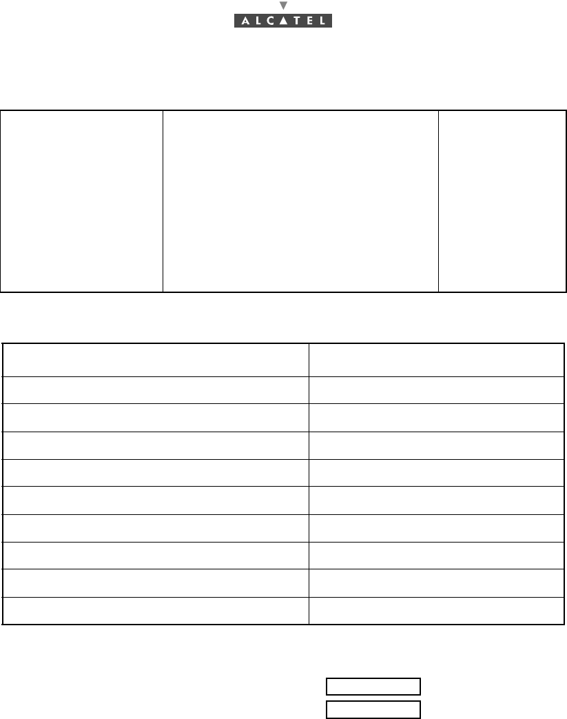
ACCEPTANCE
Green LED lighting: (OK or NO OK)
Red LED off: (OK or NO OK)
Installer: Costumer:
Date:
Name:
Visa:
88/ 114 Issue 01 - March 2001 - Draft 03 3CC12423AAAA TQ BJA 01
90
A.1.3 – 7390 RT/NT CABLING SHEET
Diagram marks
Type of cable
Length between RT and the
first element
Splitter references
Splitter serial numbers
Repeater references
Repeater ICS
Repeater serial number
75 ohm load references
Connecting diagram
Installer: Costumer:
Date:
Name:
Visa:
3CC12423AAAA TQ BJA 01 Issue 01 - March 2001 - Draft 03 89/ 114
90
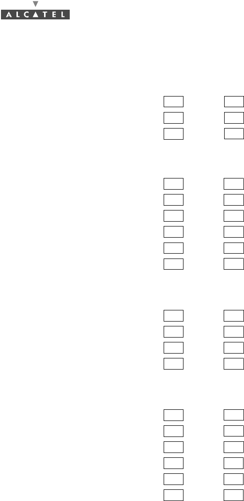
A.1.4 – LIST OF CHECKPOINTS FOR TS COMMISSIONING
CHECK SAFETY RULE
–Equipment grounding OK NOK
–Differential protection OK NOK
–Fire protection OK NOK
CHECK RT INSTALLATION
–No pollutants or possible flow on the RT OK NOK
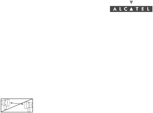
–No possible trespassing in the RT antenna field OK NOK
–Direct view between RT antenna and base station antenna OK NOK
–Use of a torque wrench for the RT assembly OK NOK
–Support stiffness and absence of vibrations OK NOK
–Same polarization as for base station antenna OK NOK
CHECK CABLES BETWEEN RT and NT
–N 75Ω connectors RT side OK NOK
–Watertightness by thermoshrinkable pre-pasted sleeve RT side OK NOK
–No cable strain OK NOK
–Observe minimum bend radius OK NOK
CHECK NT INSTALLATION
–Min Max temperature of the premises hosting the NT (-5º to + 55ºC) OK NOK
–Ventilation clearance above the NT OK NOK
–Check the NT grounding OK NOK
–Check that all client access cables are shielded cables OK NOK
–Diagram compliant with multi-NT connection OK NOK
–Repetear(s) installed indoor OK NOK

90/ 114 Issue 01 - March 2001 - Draft 03 3CC12423AAAA TQ BJA 01
90
PAGE INTENTIONALLY LEFT BLANK
3CC12423AAAA TQ BJA 01 Issue 01 - March 2001 - Draft 03 91/ 114
92
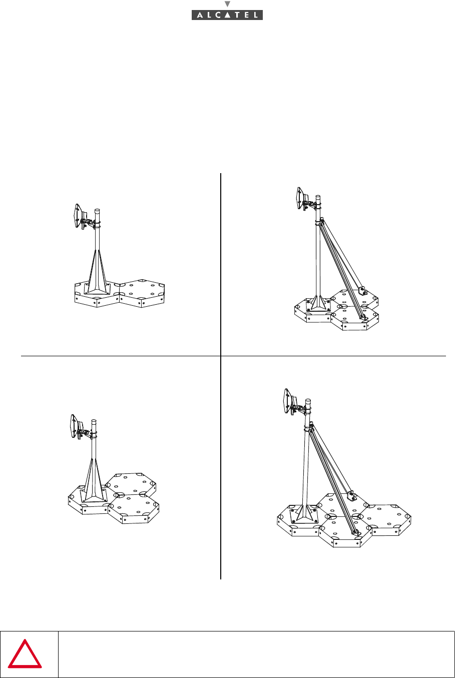
Appendix 2 – Using the DALLET® system by
SOFRER™ for 1m & 1.5m high mast on rooftop
Recommendations according to Snow and Wind Rules NV 65 are only indications and should be verified
according to the sites.
Feet weight : about 50 Kg for each DALLET.
Figure 61 – Dallet system for 26 cm antenna
Before any use, verify the rules applicable locally and
compute according to the regulations.
2 DALLET
3 DALLET
3 DALLET
4 DALLET
Zone 1 and Zone 2 Zone 1 and Zone 2
Zone 3 Zone 3
92/ 114 Issue 01 - March 2001 - Draft 03 3CC12423AAAA TQ BJA 01
92
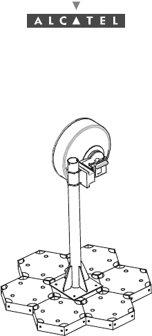
Figure 62 – Dallet system for zone 1, 2 and 3
7 DALLET
Dallet system for 60 cm antenna
3CC12423AAAA TQ BJA 01 Issue 01 - March 2001 - Draft 03 93/ 114
96
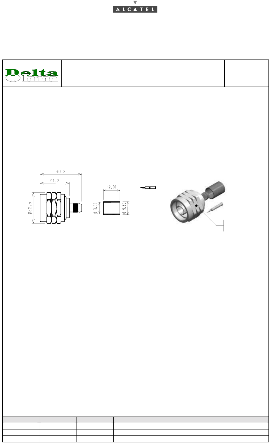
Appendix 3 – Mounting coaxial connectors
Sheet "N" 75Ω
SPECIFICATION TECHNIQUE
Fiche N mâle à sertir pour câble 75 ohms - ET 2PA 981
DSP-511
03-01-D
Page 1 sur 2
Rédigé par : Approuvé par : Edition du : / /
Mise à
j
our Par Le Ob
j
et de la mise à
j
our
B BLONDEAU 23-02-2000 Modification suivant DT 016-00
C ESTEBANEZ 06-07-2000 Modification suivant FIP 00-27-074
D ESTEBANEZ 08-03-2001 Modification suivant FIP 01-10-022
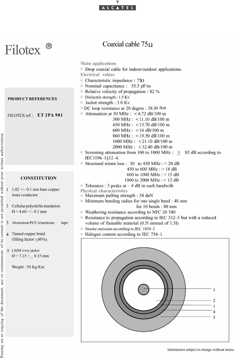
DATA SHEET
Crimp type N male plug for 75 ohms cable – ET 2PA 981
1. CODIFICATION
/ Reference.
Réf. DELTA OHM : 08 250 178
Réf. ALCATEL : 1AB019020005
2. CABLIER
/ Cable manufacturer.
Ref. FILOTEX
: ET 2PA 981
Dimension du câble
: Ame : ø1.02±0.1; Diélec. : ø4.6±0.1; Gaine : ø7.15±0.15
/ Cable dimension : Core : ø1.02±0.1; Dielectric : ø4.6±0.1; Jacket : ø7.15±0.15
3. DIMENSION
/ Dimension.
20 / plats
20 / flats
Contact à sertir
Crimping contact
4. CARACTERISTIQUE ELECTRIQUE
/ Electrical characteristic.
Impédance caractéristique
/
Characteristic impedance : 75 ΩΩ ± 2%
Fréquence d'utilisation
/
Operating frequency range : DC – 3 GHz
Résistance d'isolement
/
Insulation resistance : ≥≥ 5 x 10³³ MΩΩ
Tension de service au sol
/ Working voltage at sea level : 1 kVeff / 50 Hz
Essai de tenue en tension au sol
/ Proof voltage at sea level : 1.5 kVeff / 50 Hz
Pertes d'insertion
/ Insertion loss : ≤≤ 0.05 dB
Résistance de contact
/
Contact resistance
- Contact central
/ Center contact : ≤≤ 1 mΩΩ
- Contact extérieur
/ Outer
contact
: ≤≤ 0.2 mΩΩ
5. CARACTERISTIQUE MECANIQUE
/ Mechanical characteristic.
Matière et protection du contact central
: LAITON doré
/ Material and finish of the center contact : Gold plated brass
Matière et protection des autres parties métalliques
: LAITON nickelé
/ Material and finish of the other metal parts : Nickel plated brass
Isolant
/
Insulator : PTFE
Connecteur (accouplement)
: N mâle conforme à la norme NF C 93-566
/ Connector (coupling) : N male in compliance with NF C 93-566 standard
Traction sur le câble
/ Cable retention force : ≥≥ 2 daN
Blocage du système de verrouillage (accouplement)
: Effectué avec un couple = 0,7 N.m à 1,1 N.m
/ Locking system clamping (coupling) : Executed with torque = 0.7 N.m to 1.1 N.m
Etanchéité à l'accouplement
/ Coupling tightness : IP 67 par joint plat en SILICONE / by Silicone gasket
Température d'utilisation
/ Operating temperature range : - 40 °C << θθ << + 65 °C
Poids
/
Weight : 33 g
6. DIVERS
/ Miscellaneous.
Conditionnement
/ Packaging : unitaire / per unit
94/ 114 Issue 01 - March 2001 - Draft 03 3CC12423AAAA TQ BJA 01
96
Fiche "F" 75Ω
SPECIFICATION TECHNIQUE
Fiche N mâle à sertir pour câble 75 ohms - ET 2PA 981
DSP-511
03-01-D
Page 2 sur 2
Rédigé par : Approuvé par : Edition du : / /
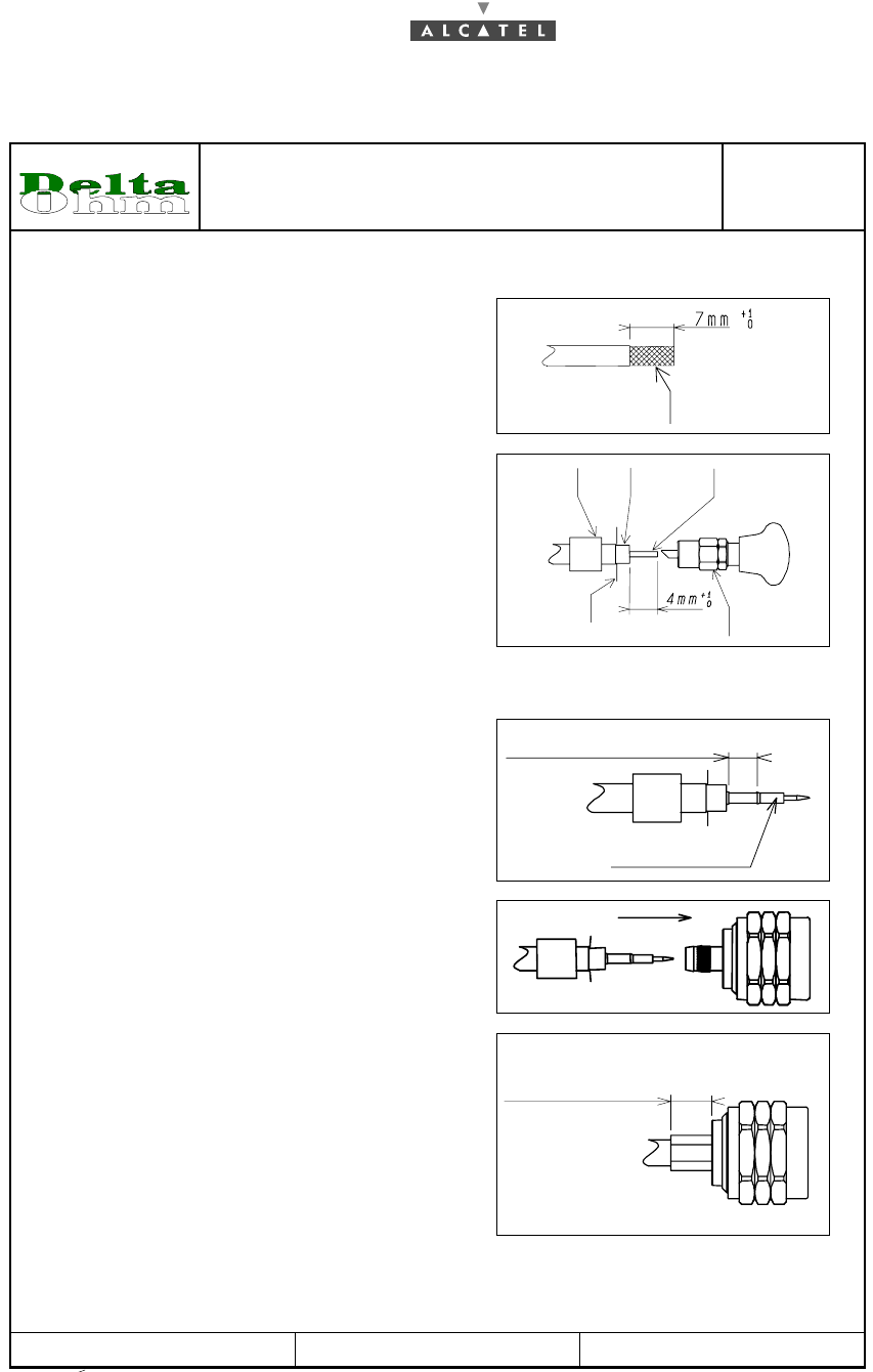
7. PREPARATION DU CABLE.
(Cable preparation).
7.1 F - Dénuder la tresse
(7 mm).
GB - Strip the braid (7 mm).
Tresse + Feuillard
Braid + Foil
7.2 F - Monter la ferrule et rabattre la tresse.
Dénuder l’âme (4 mm). Evaser entre le feuillard
et la tresse à l’aide de l’outil 22-395-036.
GB - Insert the ferrule and flange the braid.
Strip the core (4 mm). Widen between the foil
and the braid with the tool 22-395-036.
Feuillard
F
oil
Ferrule
Ferrule
Ame
Core
Tresse
Brai
d
Evaseur
Flange tool
8. MONTAGE DU CONNECTEUR.
(Mounting of the connector).
8.1 F - Monter le contact central sur l'âme du câble
et sertir celui-ci à l'aide de la pince 22-395-208
(hexagone 1,73 mm).
GB - Insert the center contact on the core of the
cable and crimp with the pliers 22-395-208
(hexagon 1,73 mm).
Zone de sertissage. Hexa. = 1,73 mm
Area for crimping. Hexa. = 1.73 mm
Contact central
Central contact
8.2 F - Insérer le câble équipé dans le corps.
Couper le surplus de tresse au ras du corps.
GB -
Insert the assembled cable into the body.
Cut the excess of braid against the body.
8.3 F - Positionner la ferrule et sertir celle-ci à l'aide
de la pince 22-395-208 (hexagone 8,3 mm).
GB - Set up the ferrule and crimp it with pliers
22-395-208 (hexagon 8,3 mm).
8,3 mm = Zone de sertissage hexa.
8.3 mm = Hexa. area for crimping
3CC12423AAAA TQ BJA 01 Issue 01 - March 2001 - Draft 03 95/ 114
96

96/ 114 Issue 01 - March 2001 - Draft 03 3CC12423AAAA TQ BJA 01
96
PAGE INTENTIONALLY LEFT BLANK
3CC12423AAAA TQ BJA 01 Issue 01 - March 2001 - Draft 03 97/ 114
98
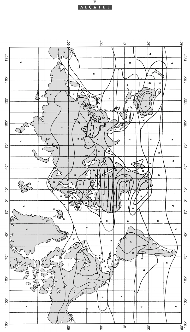
Appendix 4 – Climatic areas world map

98/ 114 Issue 01 - March 2001 - Draft 03 3CC12423AAAA TQ BJA 01
98
PAGE INTENTIONALLY LEFT BLANK

3CC12423AAAA TQ BJA 01 Issue 01 - March 2001 - Draft 03 99/ 114
104
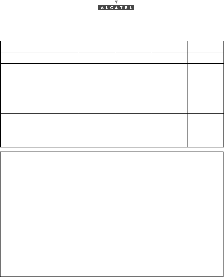
Appendix 5 – Correspondence between commercial
codes and industrial codes relating to the TS
Installation item Commercial
code Industrial code Comments
7390 NC - commercial NT
NT unit
NCA 001
(2 Eth + 2 G703) 220V 9900NCA001+
9900SWA001 3CC 10329 AAxx Without power cable
NGA 001
(2 Eth + G703, ) 48V 9900NGA001+
9900SWA001 3CC 10329 BCxx With cable 48 V
NGA 004
(2 Eth + 2G703, LEMO) 48V 9900NGA004+
9900SWA001 3CC 10329 BFxx With cable 48 V
NCA 002
(2 Eth + 1G703 + X21) 220V 9900NCA002+
9900SWA001 3CC 10329ABxx Without power cable
NCB 001
(2 Eth + 4 ISDN- 2B1Q-60 V)
220V
9900NCB001+
9900SWA001 3CC 10329 ALxx Without power cable
NGB 001
(2 Eth + 4 ISDN- 2B1Q-60 V) 48V 9900NGB001+
9900SWA001 3CC 10329 AWxx With cable 48 V
NCD 001
(2 Eth) 220V 9900NCD001+
9900SWA001 3CC 10329 ACxx Without power cable
NCE 001
(2 Eth + 2 T1 ANSI) 220V 9900NCE001+
9900SWA001 3CC 10329 AExx Without power cable
NCB 002
(2 Eth + 4 ISDN-4B3T -60 V)
220V
9900NCB002+
9900SWA001 3CC 10329 ATxx Without power cable
NGB 002
(2 Eth + 4 ISDN-4B3T -60 V) 48V 9900NGB002+
9900SWA001 3CC 10329 AZxx With cable 48 V
7390 NC - commercial NT
NT Lite unit
NCF 001
(1 Eth + 1E1 (G703)) 220V 9900NCF001+
9900SWA001 3DG 55004 AAxx Without power cable
NCG 001
(1 Eth + 1T1 ANSI) 220V 9900NCG001+
9900SWA001 3DG 55004 ADxx Without power cable
RT installation items
Indoor-outdoor cabling
coaxial cable 6F(TC) 75 Ohm 9900XTA001
70 m 1AC 00273 0003
(per meter) (70 meters)
Crimping tool Delta Ohms 9900YTB001 3CC 11239 AAxx

100/ 114 Issue 01 - March 2001 - Draft 03 3CC12423AAAA TQ BJA 01
104
Repeater (without cable) 9900XTB002 3CC 08473 AAxx
Passive Splitter (with-out cable) 9900XTC002 3CC11234AAAxx
Bended pipe (48 mm of diameter) 9900XTE001 3CC 11132 AAxx
Self-supporting mast 1 meter
(48 mm of diameter) 9900XTD002 3CC 11133 AAxx
self-supporting mast 1.5 meter
(48 mm of diameter) 9900XTD001 3CC 11134 AAxx
74/114mm-pipe adaptation kit 9900XTF001 3CC 10802 Aaxx
24-30 GHz-RT with an integrated
antenna of 26 cm 9900RTA001 3CC 11955 AAxx
3CC 11945 AAxx
24/800/A 24 GHz
RT with N connector
RT with F connector
24-30 GHz-RT with an integrated
antenna of 26 cm 9900RTA001 3CC 10884 AAxx
3CC 11589 AAxx
25/1008/A 25 GHz
RT with N connector
RT with F connector
24-30 GHz-RT with an integrated
antenna of 26 cm 9900RTA001 3CC 10884 ABxx
3CC 11589 ABxx
25/1008/B 25 GHz
RT with N connector
RT with F connector
24-30 GHz-RT with an integrated
antenna of 26 cm 9900RTA001 3CC 10884 ACxx
3CC 11589 ACxx
25/1008/C 25 GHz
RT with N connector
RT with F connector
24-30 GHz-RT with an integrated
antenna of 26 cm 9900RTA001 3CC 10884 ADxx
3CC 11589 ADxx
25/1008/D 25 GHz
RT with N connector
RT with F connector
24-30 GHz-RT with an integrated
antenna of 26 cm 9900RTA001 3CC 11196 AAxx
3CC 11943 AAxx
25/1480/A 25 GHz
RT with N connector
RT with F connector
24-30 GHz-RT with an integrated
antenna of 26 cm 9900RTA001 3CC 11196 ABxx
3CC 11943 ABxx
25/1480/B 25 GHz
RT with N connector
RT with F connector
24-30 GHz-RT with an integrated
antenna of 26 cm 9900RTA001 3CC 10885 AAxx
3CC 10944 AAxx
26/855/A 26 GHz
RT with N connector
RT with F connector
24-30 GHz-RT with an integrated
antenna of 26 cm 9900RTA001 3CC 10885 ABxx
3CC 11944 ABxx
26/855/B 26 GHz
RT with N connector
RT with F connector
24-30 GHz-RT with an integrated
antenna of 26 cm 9900RTA001 3CC 11956 AAxx
3CC 12115 AAxx
28/425/A 28 GHz
RT with N connector
RT with F connector
Installation item Commercial
code Industrial code Comments