Alcatel Canada 24T07A01D22D 7390 24 GHz Co-Pol RT User Manual NT Manual pages 1 to 25
Alcatel Canada Inc 7390 24 GHz Co-Pol RT NT Manual pages 1 to 25
Contents
NT Manual pages 1 to 25

3CC12423AAAA TQ BJA 01 - Draft 03
$OFDWHO
([
0XOWLVHUYLFHEURDGEDQGZLUHOHVV
DFFHVVVROXWLRQ
7HUPLQDO6WDWLRQUHOHDVHE
&RSRODUL]HGYHUVLRQ
8VHU0DQXDO

2/ 114 Issue 01 - March 2001 - Draft 03 3CC12423AAAA TQ BJA 01
4
Status Released
Change Note
Short Title A7390 Terminal Station - release 2.2b
All rights reserved. Passing on and copying of this
document, use and communication of its contents not
permitted without written authorization from Alcatel.

3CC12423AAAA TQ BJA 01 Issue 01 - March 2001 - Draft 03 3/ 114
4
Customer Service Support:
a Team tuned to your needs for your entire satisfaction
Congratulations on having bought your equipment from Alcatel.
We hope that it will give you full satisfaction.
For any additional information or if you have any questions concerning this equipment, please contact
the Technical Assistance Center, (TAC) dedicated to your support whose coordinates have been
given to you by the Alcatel Contract Manager or:
http://www.cid.alcatel.com/support .
You must specify the hardware and software configurations of each item concerned when getting in
touch.
This service, available on subscription, is free for the duration of the initial waranty period.

4/ 114 Issue 01 - March 2001 - Draft 03 3CC12423AAAA TQ BJA 01
4
PAGE INTENTIONALLY LEFT BLANK

3CC12423AAAA TQ BJA 01 Issue 01 - March 2001 - Draft 03 5/ 114
8
Table of contents
1 – Foreword . . . . . . . . . . . . . . . . . . . . . . . . . . . . . . . . . . . . . . . . . . . . . . . . . . . . . . . . . . . . . . . . . . 9
1.1 – Structure of the manual . . . . . . . . . . . . . . . . . . . . . . . . . . . . . . . . . . . . . . . . . . . . . . . . . . . 9
1.2 – Using the manual. . . . . . . . . . . . . . . . . . . . . . . . . . . . . . . . . . . . . . . . . . . . . . . . . . . . . . . . 9
1.3 – Safety instructions . . . . . . . . . . . . . . . . . . . . . . . . . . . . . . . . . . . . . . . . . . . . . . . . . . . . . . . 10
1.3.1 – General rules. . . . . . . . . . . . . . . . . . . . . . . . . . . . . . . . . . . . . . . . . . . . . . . . . . . . . 10
1.3.2 – Symbols on products. . . . . . . . . . . . . . . . . . . . . . . . . . . . . . . . . . . . . . . . . . . . . . . 10
1.3.3 – Symbols used in the document . . . . . . . . . . . . . . . . . . . . . . . . . . . . . . . . . . . . . . . 11
1.3.4 – Declaration of conformity with European policies relating to EMC . . . . . . . . . . . . 12
2 Equipment overview . . . . . . . . . . . . . . . . . . . . . . . . . . . . . . . . . . . . . . . . . . . . . . . . . . . . . . . . . . 15
2.1 Overview of the A7390 system . . . . . . . . . . . . . . . . . . . . . . . . . . . . . . . . . . . . . . . . . . . . . . . 15
2.2 Composition of the A7390 system . . . . . . . . . . . . . . . . . . . . . . . . . . . . . . . . . . . . . . . . . . . . 16
2.3 A7390 system specifications . . . . . . . . . . . . . . . . . . . . . . . . . . . . . . . . . . . . . . . . . . . . . . . .17
2.3.1 Frequency bands used . . . . . . . . . . . . . . . . . . . . . . . . . . . . . . . . . . . . . . . . . . . . . . . 17
2.3.2 Radio transmission specifications (typical values) . . . . . . . . . . . . . . . . . . . . . . . . . . 17
2.3.3 Capacity . . . . . . . . . . . . . . . . . . . . . . . . . . . . . . . . . . . . . . . . . . . . . . . . . . . . . . . . . . 18
2.4 Description of the Terminal Station (7390TS). . . . . . . . . . . . . . . . . . . . . . . . . . . . . . . . . . . . 20
2.5 Examples of configuration of the Terminal Station (7390TS) . . . . . . . . . . . . . . . . . . . . . . . . 20
2.5.1 Mono "NT" without repeater . . . . . . . . . . . . . . . . . . . . . . . . . . . . . . . . . . . . . . . . . . . 20
2.5.2 Mono "NT" with repeater. . . . . . . . . . . . . . . . . . . . . . . . . . . . . . . . . . . . . . . . . . . . . . 20
2.5.3 Multi "NT" with passive splitters and repeaters. . . . . . . . . . . . . . . . . . . . . . . . . . . . . 21
2.6 Technical specifications of the Terminal Station (7390TS). . . . . . . . . . . . . . . . . . . . . . . . . . 22
2.6.1 RT specifications . . . . . . . . . . . . . . . . . . . . . . . . . . . . . . . . . . . . . . . . . . . . . . . . . . . 22
2.6.2 NT specifications . . . . . . . . . . . . . . . . . . . . . . . . . . . . . . . . . . . . . . . . . . . . . . . . . . . 22
2.7 Equipment power consumption . . . . . . . . . . . . . . . . . . . . . . . . . . . . . . . . . . . . . . . . . . . . . . 23
3 Installation of the 7390TS Terminal Station . . . . . . . . . . . . . . . . . . . . . . . . . . . . . . . . . . . . . . . 25
3.1 Equipment delivery . . . . . . . . . . . . . . . . . . . . . . . . . . . . . . . . . . . . . . . . . . . . . . . . . . . . . . . . 25
3.1.1 Unpacking. . . . . . . . . . . . . . . . . . . . . . . . . . . . . . . . . . . . . . . . . . . . . . . . . . . . . . . . .25
3.1.2 Checking the configuration . . . . . . . . . . . . . . . . . . . . . . . . . . . . . . . . . . . . . . . . . . . . 27
3.2 Labels on the equipment . . . . . . . . . . . . . . . . . . . . . . . . . . . . . . . . . . . . . . . . . . . . . . . . . . . 28
3.3 Installing the equipment . . . . . . . . . . . . . . . . . . . . . . . . . . . . . . . . . . . . . . . . . . . . . . . . . . . . 29
3.3.1 Information required for installation . . . . . . . . . . . . . . . . . . . . . . . . . . . . . . . . . . . . . 29
3.3.2 Precautions concerning electromagnetic compatibility. . . . . . . . . . . . . . . . . . . . . . . 29
3.3.3 Tools required. . . . . . . . . . . . . . . . . . . . . . . . . . . . . . . . . . . . . . . . . . . . . . . . . . . . . .29
3.4 Installation of the Terminal Station RT unit with an integrated antenna . . . . . . . . . . . . . . . . 31
3.4.1 Definition of assemblies with respect to chosen polarization . . . . . . . . . . . . . . . . . . 31
3.4.2 Installation of the 7390 RT on a wall or flat vertical surface . . . . . . . . . . . . . . . . . . . 33
3.4.3 Installation of the RT unit on a tube for «N» or «F» connector RT . . . . . . . . . . . . . . 35
3.4.4 Grounding the RT unit . . . . . . . . . . . . . . . . . . . . . . . . . . . . . . . . . . . . . . . . . . . . . . . 41
3.5 Installation of the Terminal Station RT unit with a non integrated antenna. . . . . . . . . . . . . . 42
3.6 Installation of the RT/NT link. . . . . . . . . . . . . . . . . . . . . . . . . . . . . . . . . . . . . . . . . . . . . . . . . 42
3.7 Installation of the Terminal Station 7390 NT (Indoor Unit) . . . . . . . . . . . . . . . . . . . . . . . . . . 44
3.7.1 Installation of the 7390NT unit on a desktop . . . . . . . . . . . . . . . . . . . . . . . . . . . . . . 44
3.7.2 Installation of the NT unit on a 19" rack . . . . . . . . . . . . . . . . . . . . . . . . . . . . . . . . . . 45
3.7.3 Earthing the NT units . . . . . . . . . . . . . . . . . . . . . . . . . . . . . . . . . . . . . . . . . . . . . . . . 45
3.8 Installation of one or more repeater modules . . . . . . . . . . . . . . . . . . . . . . . . . . . . . . . . . . . . 46
3.9 Installation of one or several repeaters with splitter(s) . . . . . . . . . . . . . . . . . . . . . . . . . . . . . 48
3.9.1 Installation directions for an assembly with 2 NT units. . . . . . . . . . . . . . . . . . . . . . . 48
3.9.2 Installation directions for an assembly with 4 NT or 8 NT units (*) . . . . . . . . . . . . . . 50

6/ 114 Issue 01 - March 2001 - Draft 03 3CC12423AAAA TQ BJA 01
8
4 Commissioning the 7390 TS Terminal Station . . . . . . . . . . . . . . . . . . . . . . . . . . . . . . . . . . . . . 53
4.1 Purpose . . . . . . . . . . . . . . . . . . . . . . . . . . . . . . . . . . . . . . . . . . . . . . . . . . . . . . . . . . . . . . . . 53
4.2 Commissioning the RT unit. . . . . . . . . . . . . . . . . . . . . . . . . . . . . . . . . . . . . . . . . . . . . . . . . .53
4.2.1 Equipment required . . . . . . . . . . . . . . . . . . . . . . . . . . . . . . . . . . . . . . . . . . . . . . . . . 53
4.2.2 E-RIT Tool . . . . . . . . . . . . . . . . . . . . . . . . . . . . . . . . . . . . . . . . . . . . . . . . . . . . . . . .54
4.2.3 Site configuration and adjustment procedures . . . . . . . . . . . . . . . . . . . . . . . . . . . . . 55
4.3 Commissioning the NT . . . . . . . . . . . . . . . . . . . . . . . . . . . . . . . . . . . . . . . . . . . . . . . . . . . . . 70
4.4 Client terminal connections (NT unit) . . . . . . . . . . . . . . . . . . . . . . . . . . . . . . . . . . . . . . . . . . 73
4.4.1 Ethernet connector . . . . . . . . . . . . . . . . . . . . . . . . . . . . . . . . . . . . . . . . . . . . . . . . . . 73
4.4.2 G703 connector (120 ohm E1 and 100 ohm T1 standards) . . . . . . . . . . . . . . . . . . . 73
4.4.3 X21 connector . . . . . . . . . . . . . . . . . . . . . . . . . . . . . . . . . . . . . . . . . . . . . . . . . . . . . 74
4.4.4 ISDN connector (Norm TS 102 - 080) . . . . . . . . . . . . . . . . . . . . . . . . . . . . . . . . . . . 74
4.4.5 48V connector (HE 15) . . . . . . . . . . . . . . . . . . . . . . . . . . . . . . . . . . . . . . . . . . . . . . . 75
4.5 Client terminal connections (NT Lite unit). . . . . . . . . . . . . . . . . . . . . . . . . . . . . . . . . . . . . . . 75
4.5.1 Ethernet connector . . . . . . . . . . . . . . . . . . . . . . . . . . . . . . . . . . . . . . . . . . . . . . . . . . 75
4.5.2 G703 connector (120 ohm E1 and 100 ohm T1 standards) . . . . . . . . . . . . . . . . . . . 76
4.6 Initiating services . . . . . . . . . . . . . . . . . . . . . . . . . . . . . . . . . . . . . . . . . . . . . . . . . . . . . . . . . 76
4.7 Filling in the installation sheet. . . . . . . . . . . . . . . . . . . . . . . . . . . . . . . . . . . . . . . . . . . . . . . . 76
4.7.1 7390 RT installation sheet . . . . . . . . . . . . . . . . . . . . . . . . . . . . . . . . . . . . . . . . . . . . 76
4.7.2 NT installation sheet . . . . . . . . . . . . . . . . . . . . . . . . . . . . . . . . . . . . . . . . . . . . . . . . . 77
4.7.3 RT/NT wiring sheet. . . . . . . . . . . . . . . . . . . . . . . . . . . . . . . . . . . . . . . . . . . . . . . . . . 77
5 Operation and maintenance . . . . . . . . . . . . . . . . . . . . . . . . . . . . . . . . . . . . . . . . . . . . . . . . . . . . 79
5.1 7390 system supervision . . . . . . . . . . . . . . . . . . . . . . . . . . . . . . . . . . . . . . . . . . . . . . . . . . . 79
5.2 Preventive maintenance . . . . . . . . . . . . . . . . . . . . . . . . . . . . . . . . . . . . . . . . . . . . . . . . . . . . 79
5.3 Corrective maintenance . . . . . . . . . . . . . . . . . . . . . . . . . . . . . . . . . . . . . . . . . . . . . . . . . . . . 79
5.4 Changing a faulty NT unit . . . . . . . . . . . . . . . . . . . . . . . . . . . . . . . . . . . . . . . . . . . . . . . . . . . 79
5.5 Changing a faulty RT unit . . . . . . . . . . . . . . . . . . . . . . . . . . . . . . . . . . . . . . . . . . . . . . . . . . . 80
6 Changes of configuration . . . . . . . . . . . . . . . . . . . . . . . . . . . . . . . . . . . . . . . . . . . . . . . . . . . . . . 81
6.1 Declaration, deletion, reset of an NT . . . . . . . . . . . . . . . . . . . . . . . . . . . . . . . . . . . . . . . . . . 81
6.2 Implementation of client services . . . . . . . . . . . . . . . . . . . . . . . . . . . . . . . . . . . . . . . . . . . . .82
6.3 Changing an RT . . . . . . . . . . . . . . . . . . . . . . . . . . . . . . . . . . . . . . . . . . . . . . . . . . . . . . . . . . 82
6.4 Adding an NT to a cluster . . . . . . . . . . . . . . . . . . . . . . . . . . . . . . . . . . . . . . . . . . . . . . . . . . . 83
6.4.1 Case of a pre-wired installation . . . . . . . . . . . . . . . . . . . . . . . . . . . . . . . . . . . . . . . . 83
6.4.2 Case of a non-pre-wired installation . . . . . . . . . . . . . . . . . . . . . . . . . . . . . . . . . . . . . 83
6.5 Affectation of an NT to another BS . . . . . . . . . . . . . . . . . . . . . . . . . . . . . . . . . . . . . . . . . . . . 83
Appendix 1 – 7390 TS installation sheet. . . . . . . . . . . . . . . . . . . . . . . . . . . . . . . . . . . . . . . . . . . . 85
A.1.1 – 7390 RT INSTALLATION SHEET . . . . . . . . . . . . . . . . . . . . . . . . . . . . . . . . . . . . . . . . . 85
A.1.2 – 7390 NT INSTALLATION SHEET . . . . . . . . . . . . . . . . . . . . . . . . . . . . . . . . . . . . . . . . . 87
A.1.3 – 7390 RT/NT CABLING SHEET . . . . . . . . . . . . . . . . . . . . . . . . . . . . . . . . . . . . . . . . . . . 88
A.1.4 – LIST OF CHECKPOINTS FOR TS COMMISSIONING . . . . . . . . . . . . . . . . . . . . . . . . . 89
Appendix 2 – Using the DALLET® system by SOFRER™ for 1m & 1.5m high mast on rooftop 91
Appendix 3 – Mounting coaxial connectors. . . . . . . . . . . . . . . . . . . . . . . . . . . . . . . . . . . . . . . . . 93
Appendix 4 – Climatic areas world map . . . . . . . . . . . . . . . . . . . . . . . . . . . . . . . . . . . . . . . . . . . . 97

3CC12423AAAA TQ BJA 01 Issue 01 - March 2001 - Draft 03 7/ 114
8
Appendix 5 – Correspondence between commercial codes and industrial codes relating
to the TS . . . . . . . . . . . . . . . . . . . . . . . . . . . . . . . . . . . . . . . . . . . . . . . . . . . . . . . . . . . . . . . . . . . . . . 99
Appendix 6 – Installation of the Terminal Station RT unit with a non integrated antenna . . . 105
A.6.1 – Choosing antenna polarization. . . . . . . . . . . . . . . . . . . . . . . . . . . . . . . . . . . . . . . . . . . . 106
A.6.2 – Installing the configuration with pole mounting 1+0 (9900UXI102) . . . . . . . . . . . . . . . . 107
A.6.2.1 – Installing the antenna on the pole mounting . . . . . . . . . . . . . . . . . . . . . . . . . . 108
A.6.2.2 – Installing the RT unit . . . . . . . . . . . . . . . . . . . . . . . . . . . . . . . . . . . . . . . . . . . . 108
A.6.2.3 – Installing on the pipe . . . . . . . . . . . . . . . . . . . . . . . . . . . . . . . . . . . . . . . . . . . . 109
A.6.2.4 – Coarse alignment of the antenna . . . . . . . . . . . . . . . . . . . . . . . . . . . . . . . . . . . 109
A.6.3 – Grounding the RT unit . . . . . . . . . . . . . . . . . . . . . . . . . . . . . . . . . . . . . . . . . . . . . . . . . . 112
Appendix 7 – List of abbreviations . . . . . . . . . . . . . . . . . . . . . . . . . . . . . . . . . . . . . . . . . . . . . . . . 113

8/ 114 Issue 01 - March 2001 - Draft 03 3CC12423AAAA TQ BJA 01
8
PAGE INTENTIONALLY LEFT BLANK

3CC12423AAAA TQ BJA 01 Issue 01 - March 2001 - Draft 02 9/ 108
14
1–Foreword
1.1–Structure of the manual
This manual is intended for users with a sound knowledge of how to operate and install point-multipoint
microwave systems and how to use a PC-based craft terminal running the Windows operating
system.
With it, you should quickly be able to operate the equipment. It is not intended to replace the training
services that we can provide for your particular needs.
The manual is divided into seven sections followed by an appendix:
–Foreword
–AMD Radio Performance tool overview
–Installation of the AMD Radio Performance tool
–DBS – PC connection
–Running AMD Radio Performance tool
–Results
–Margin calculation
–Appendix
1.2–Using the manual
With this manual, you should be able to commission and operate the described equipment to a basic
level.
You should always read this manual in conjunction with the attached "Update" document (if provided)
to make you aware of the latest equipment upgrades.
Manual updates
This edition of the manual describes hardware and software releases whose revision indexes are greater
than or equal to those given below:
Hardware revision: 01
In cases where an equipment upgrade affects the content of the manual, the relevant modification should
be inserted in the "Update" document, with the same reference number, but with code type VE (instead
of TQ).
When the number or extent of the changes justifies it, they should be incorporated in the body of the
manual and the manual’s revision index should be incremented. Revision bars will show the differences
from the previous version.
Note: MS-DOS, MICROSOFT and WINDOWS are registered trademarks of Microsoft Corporation.

10/ 108 Issue 01 - March 2001 - Draft 02 3CC12423AAAA TQ BJA 01
14
1.3–Safety instructions
1.3.1 –General rules
The following general safety precautions must be observed by the installer and the operator.
ALCATEL assumes no liability for the customer’s failure to comply with these requirements.
–Ground the equipment: for Safety Class 1 equipment, always connect the earth conductor of the
power cable to an appropriate earthing device.
–DO NOT operate the product in an explosive atmosphere or in presence of flammable ga-
ses or fumes.
–For protection against fire: replace the line fuse(s) only with fuse(s) of the same voltage and
current rating and type.
–Dangerous voltages: users must not remove equipment covers or shields. The installation and
maintenance procedures described in this manual are for use by service-trained personnel only.
–Protection against short circuits: the mains equipment should ensure protection against short
circuits according to current domestic standards (residual current differential protection device re-
commended).
–Observe the standards in force for all activities carried out on the roofs.
–For any on-site intervention, observe the precautions against lightning.
–DO NOT operate equipment which may be damaged: its level protection may be altered.
–Whenever it is possible that the safety protection features built into this equipment have been im-
paired, ISOLATE FROM THE POWER SUPPLY and do not use the equipment until safe opera-
tion can be verified by service-trained personnel. If necessary, return the equipment to Alcatel
After Sales for service and repair.
–DO NOT open equipment.
–Return the product to Alcatel Customer Service for servicing and repair.
–Recommendation to installers and maintenance operators: before carrying out any opera-
tions, check the equipotential bonding of the earthing devices to which our measurement equip-
ment and instruments are connected. If necessary, during installation, ensure the equipotential
bonding by electrical connection of these devices.
1.3.2 –Symbols on products
1.3.2.1 –Danger symbols
When subsystems and modules have warning labels, it is extremely important to follow their instructions.
These labels are designed to indicate dangerous situations; they may contain any standard symbol or
any text considered necessary to protect users and employees.
The most frequent danger situations and symbols are:
Danger or general warning
Prompts the user to refer to the manual.
3CC12423AAAA TQ BJA 01 Issue 01 - March 2001 - Draft 02 11/ 108
14
Dangerous electrical voltages
1.3.2.2 –Earth symbols
1.3.2.3 –Other symbols
1.3.3 –Symbols used in the document
These symbols alert the reader the possible risks. They indicate:
–the cause and type of danger,
–the possible consequences,
–the preventive action.
1.3.3.1 –Warning
1.3.3.2 –Precautions
Close to dangerous voltages (>42.4 V AC peak, 60 V DC; power level 4240 VA) you
will find this warning label. Maintenance personnel is exposed to dangerous electri-
cal voltages when removing the cover.
Terminal for connecting the protective earth conductor in power supply wiring
Other earth terminal
Indicates compliance with essential requirements of the applicable European direc-
tives.
–protection of personnel,
–warning of a possible dangerous situation,
–danger of fatal or serious injury.
–protection of equipment,
–warning of a procedure, practice or condition that could be dangerous to equi-
pment or its environment,
–danger of damage to the equipment or its environment,
–permanent loss of data possible.
–This symbol, introducing the description of a procedure, indicates that it will
cause the link to be temporarily disconnected.

12/ 108 Issue 01 - March 2001 - Draft 02 3CC12423AAAA TQ BJA 01
14
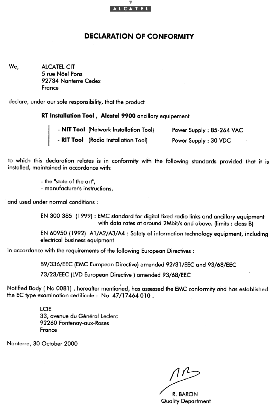
1.3.4 –Declaration of conformity with European policies relating to EMC
3CC12423AAAA TQ BJA 01 Issue 01 - March 2001 - Draft 02 13/ 108
14

14/ 108 Issue 01 - March 2001 - Draft 02 3CC12423AAAA TQ BJA 01
14
PAGE INTENTIONALLY LEFT BLANK
3CC12423AAAA TQ BJA 01 Issue 01 - March 2001 - Draft 03 15/ 114
24
2 Equipment overview
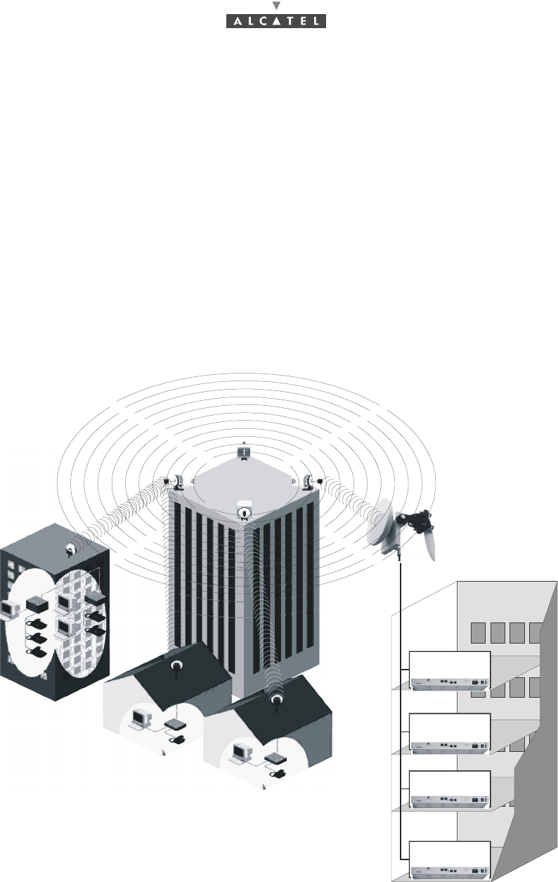
2.1 Overview of the A7390 system
The Alcatel 7390 is a multi-service broadband wireless local loop system designed to provide telecom
services to small and medium-sized enterprises.
Broad band WLL (Wireless Local Loop) system, Alcatel 7390 allows operators to offer rapid provision -
to a large number of client sites - of a comprehensive range of telephone and data transmission
services.
For cellular phone network operators, Alcatel 7390 offers the possibility of linking base stations to
base station controllers. This makes Alcatel 7390 an economical transmission solution, for the
implementation or extension of high traffic density areas coverage.
For mixed network operators (fixed and mobile), Alcatel 7390 enables to connect, with the same
system, fixed professional end user as well as base stations of cellular telephony.
Figure 1 – A7390 System - Local point - multipoint service distribution -
SME
Independant profession
Independant profession
Compagny D
Compagny A
Compagny B
Compagny C
16/ 114 Issue 01 - March 2001 - Draft 03 3CC12423AAAA TQ BJA 01
24
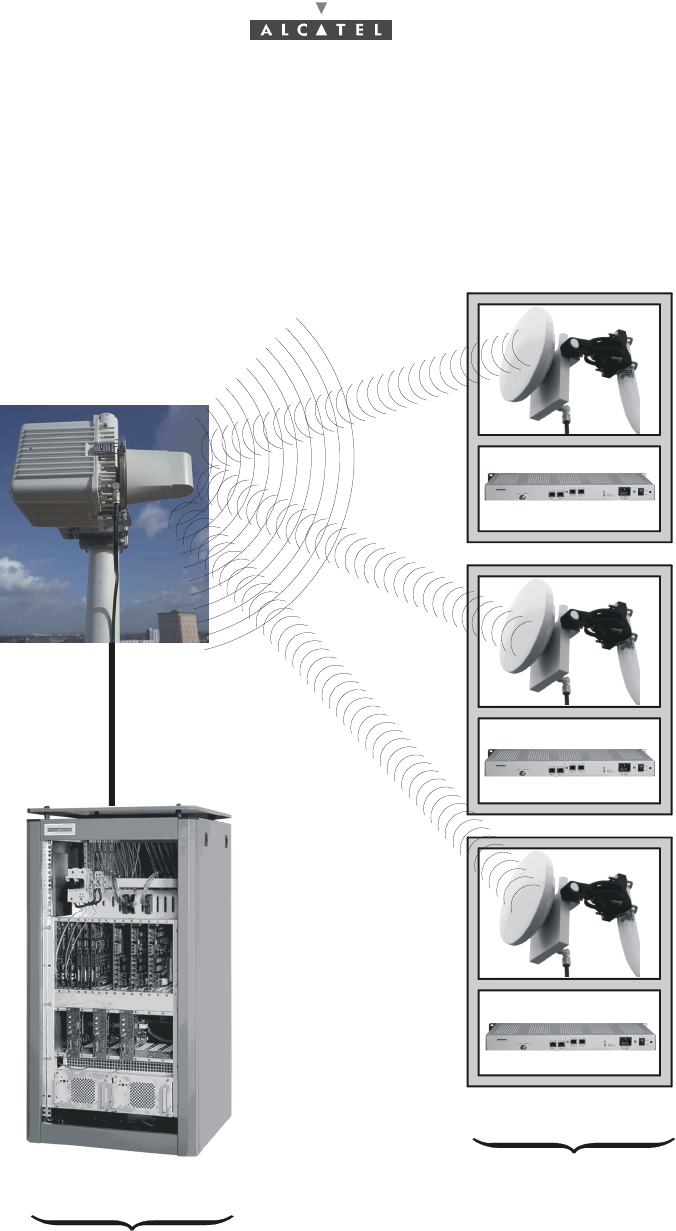
2.2 Composition of the A7390 system
An A7390 network cell consists of the following:
–a common base station designated 7390BS;
–and several terminal stations distributed across the user sites, and designated 7390TS.
Figure 2 – Base Station and Terminal Stations
"Digital Base Station" DBS
"Terminal Stations"
7390BS
nx7390TS
"Radio Base Station" RBS

3CC12423AAAA TQ BJA 01 Issue 01 - March 2001 - Draft 03 17/ 114
24
2.3 A7390 system specifications
2.3.1 Frequency bands used
25 GHz frequency band:
–CEPT T/R 13-02E European recommendation 24.5 - 26.5 GHz
26 GHz frequency band:
–MPT (Japan) 25.25 - 27 GHz
–Korea 24.25 - 24.59 ; 25.73 - 26.07 GHz
28 GHz frequency band:
–27 GHz (LMCS - Canada) 27.35 - 28.35
–28 GHz (CEPT) 28.0 - 28.5, 29.0 - 29.5
–29 GHz (LMDS - USA) 27.5 - 28.35, 29.10 - 29.25
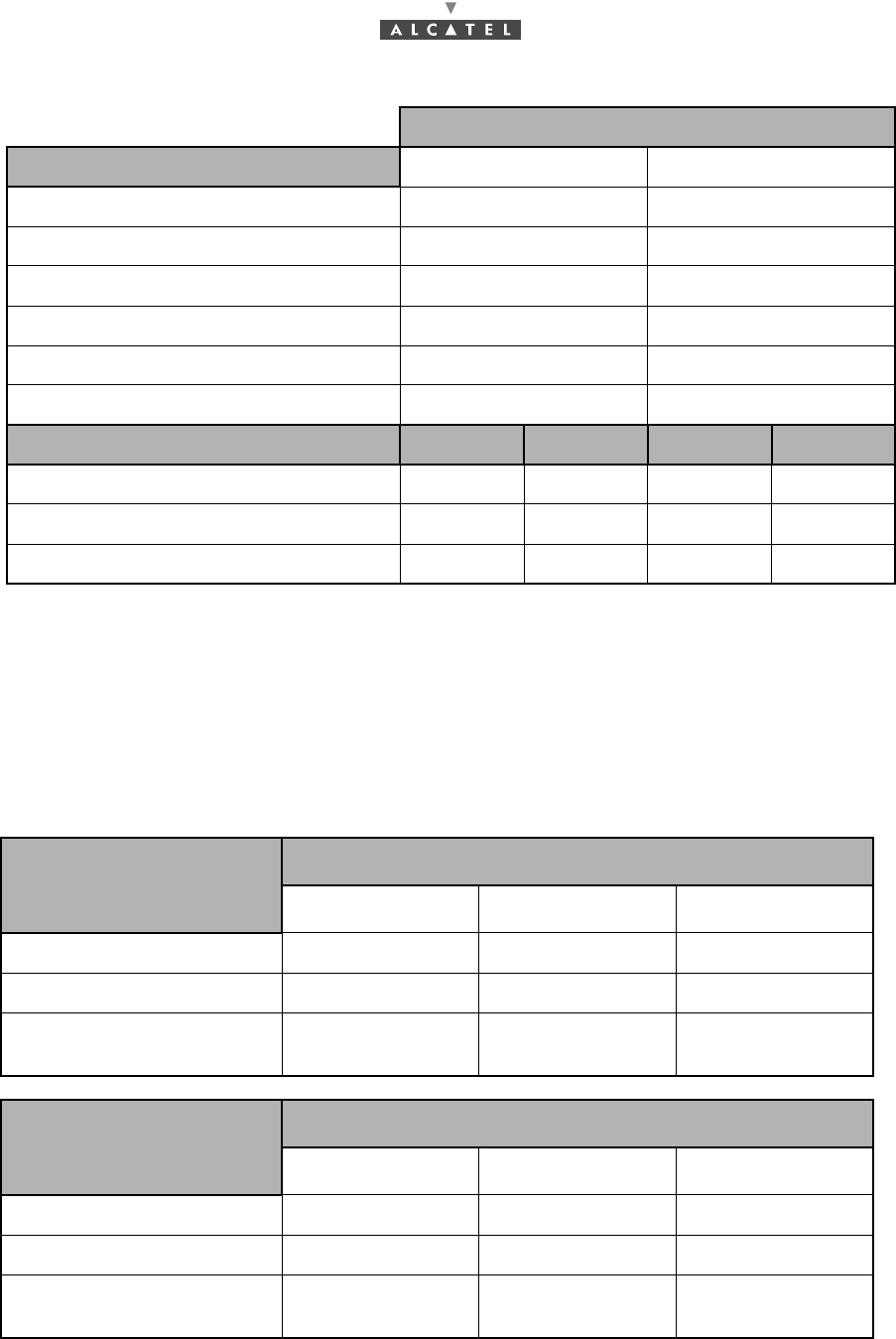
2.3.2 Radio transmission specifications (typical values)
The following table gives the main characteristics of the A7390 wireless system.
A downstream (BS to TS) carrier is combined with up to four upstream (TS to BS) carriers.
Downstream
Channel bandwidth 14 MHz 28 MHz
Occupied bandwidth 13.63 MHz 27.25 MHz
Roll-off factor 35% 35%
Modulation QPSK QPSK
Gross bit rate 20.19 Mbit/s 40.37 Mbit/s
Inner Code Convol. 7/8 (k=7) Convol.7/8 (k=7)
Interleaving depth 12 depth 12
Outer Code Reed-Solomon
(204,188, 8) Reed-Solomon
(204,188, 8)
Bit rate before coding 16.19 Mbit/s 32.38 Mbit/s
Radio 25 GHz 28 GHz 25 GHz 28 GHz
RBS output power (antenna port) 17 dBm 17 dBm 17 dBm 17 dBm
Transmit antenna gain 15 dB 15 dB 15 dB 15 dB
Receive antenna gain (with radome) 35 dB 34.5 dB 35 dB 34.5 dB
18/ 114 Issue 01 - March 2001 - Draft 03 3CC12423AAAA TQ BJA 01
24
2.3.3 Capacity
The system capacity depends on the traffic mix between data services (transported on ATM cells) and
leased lines or telephony services (transported on TDM circuits)
It also depends on the channeling and the number of upstream channels.
Figures are given in the following tables for three mix examples : minimum, medium and maximum
circuit capacity but any intermediate mix is possible.
28 / 7 MHz channeling:
Upstream
Channel bandwidth 3.5 MHz 7 MHz
Occupied bandwidth 3.36 MHz 6.72 MHz
Roll-off factor 25% 25%
Modulation D-QPSK D-QPSK
Gross bit rate 5.38 Mbit/s 10.75 Mbit/s
Outer Code Reed-Solomon (63,53,5) Reed-Solomon (63,53,5)
Bit rate before coding 4.19 Mbit/s 8.38 Mbit/s
Radio 25 GHz 28 GHz 25 GHz 28 GHz
TS output power (antenna port) 14 dBm 14 dBm 14 dBm 14 dBm
Transmit antenna gain 35 dB 34.5 dB 35 dB 34.5 dB
Receive antenna gain (with radome) 15 dB 15 dB 15 dB 15 dB
Downlink: 28 MHz Trafic MIX: circuit capacity
Uplink: 1 x 7 MHz Minimum Medium Maximum
Nb of circuits: 64 kbit/s 0 60 120
ATM uplink capacity (cells/s) 18.823 9.412 0
ATM downlink capacity
(cells/s) 75.512 66.530 57.399
Downlink : 28 MHz Trafic MIX: circuit capacity
Uplink : 2 x 7 MHz Minimum Medium Maximum
Nb of circuits: 64 kbit/s 0 120 240
ATM uplink capacity (cells/s) 37.647 18.823 0
ATM downlink capacity
(cells/s) 75.512 57.548 39.286

3CC12423AAAA TQ BJA 01 Issue 01 - March 2001 - Draft 03 19/ 114
24
14/3.5 MHz channeling:
Downlink : 28 MHz Trafic MIX: circuit capacity
Uplink : 3 x 7 MHz Minimum Medium Maximum
Nb of circuits: 64 kbit/s 0 180 360
ATM uplink capacity (cells/s) 56.471 28.235 0
ATM downlink capacity
(cells/s) 75.512 48.566 21.173
Downlink : 28 MHz Trafic MIX: circuit capacity
Uplink : 4 x 7 MHz Minimum Medium Maximum
Nb of circuits: 64 kbit/s 0 240 480
ATM uplink capacity (cells/s) 75.294 37.647 0
ATM downlink capacity
(cells/s) 75.512 39.585 3.084
Downlink: 14 MHz Trafic MIX: circuit capacity
Uplink: 1 x 3.5 MHz Minimum Medium Maximum
Nb of circuits: 64 kbit/s 0 30 60
ATM uplink capacity (cells/s) 9.412 4.706 0
ATM downlink capacity
(cells/s) 38.047 33.519 28.990
Downlink : 14 MHz Trafic MIX: circuit capacity
Uplink : 2 x 3.5 MHz Minimum Medium Maximum
Nb of circuits: 64 kbit/s 0 60 120
ATM uplink capacity (cells/s) 18.824 9.412 0
ATM downlink capacity
(cells/s) 38.047 28.990 19.934
Downlink : 14 MHz Trafic MIX: circuit capacity
Uplink : 3 x 3.5 MHz Minimum Medium Maximum
Nb of circuits: 64 kbit/s 0 90 180
ATM uplink capacity (cells/s) 28.235 14.118 0
ATM downlink capacity
(cells/s) 38.047 24.462 10.877
20/ 114 Issue 01 - March 2001 - Draft 03 3CC12423AAAA TQ BJA 01
24
2.4 Description of the Terminal Station (7390TS)
The A7390 system Terminal Station (7390TS) consists of the following main elements:
–an external transceiver constituting the radio antenna part and designated "RT" (Radio Termina-
tion);
–a user connection unit constituting the "indoor" part and designated NT (Network Termination);
–a cable linking the RT and NT (NT/RT link);
–depending on the configurations (see sections 2.5, 3.8, 3.9), one (or more) repeater module(s),
or (and) one (or more) splitter module(s).
2.5 Examples of configuration of the Terminal Station
(7390TS)
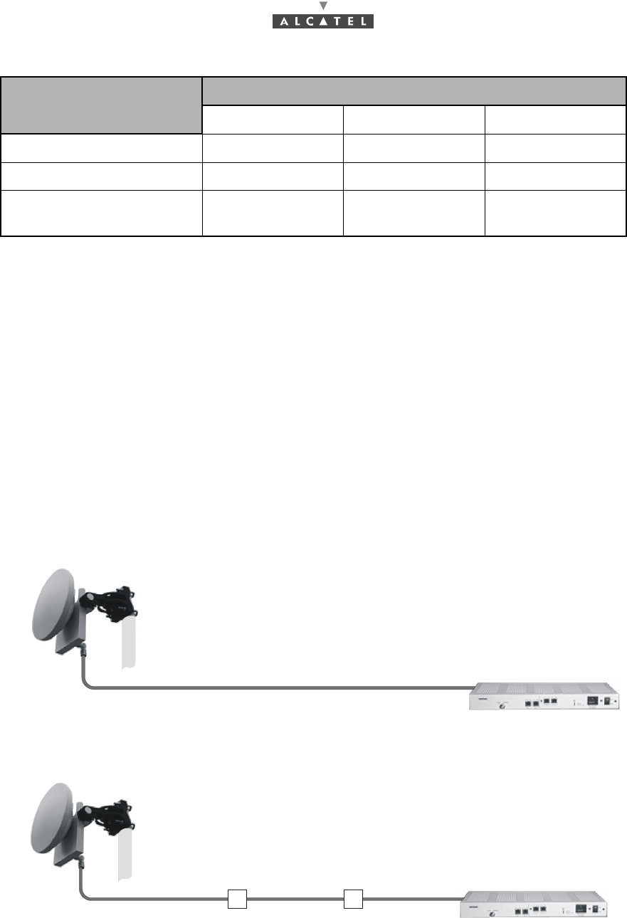
2.5.1 Mono "NT" without repeater
2.5.2 Mono "NT" with repeater
A repeater compensates 70 meters of cable.
The system can support maximum three 70 m cable sections and two repeaters.
Downlink : 14 MHz Trafic MIX: circuit capacity
Uplink : 4 x 3.5 MHz Minimum Medium Maximum
Nb of circuits: 64 kbit/s 0 120 240
ATM uplink capacity (cells/s) 37.647 18.824 0
ATM downlink capacity
(cells/s) 38.047 19.934 1.821
0 to 70 m
RT
NT
repeater repeater
0 to 70 m
RT
NT
Fixed lenght:
70 m Fixed lenght:
70 m

3CC12423AAAA TQ BJA 01 Issue 01 - March 2001 - Draft 03 21/ 114
24
2.5.3 Multi "NT" with passive splitters and repeaters
Figure 3 – Example of assembly with passive splitters and repeaters
The system can support 2 repeaters and 2 passive splitters per route. The route is the path between a
NT unit and a RT unit.
The fixed distance between 2 repeaters or between a repeater and a NT unit is 50 meters if one passive
splitter is used.
The fixed distance between two repeaters or between a repeater and a NT unit is 24 meters if two
passive splitters are used.
RT
repeater
repeater
splitter
splitter
94 m
repeater
splitter
NT1
NT2 NT5
NT4
24 m
15 to 50 meters
75 Ohms
active splitter
NT3 NT6
splitter splitter splitter splitter
repeater
75 Ohms
repeater
94 m
24 m
22/ 114 Issue 01 - March 2001 - Draft 03 3CC12423AAAA TQ BJA 01
24
2.6 Technical specifications of the Terminal Station
(7390TS)
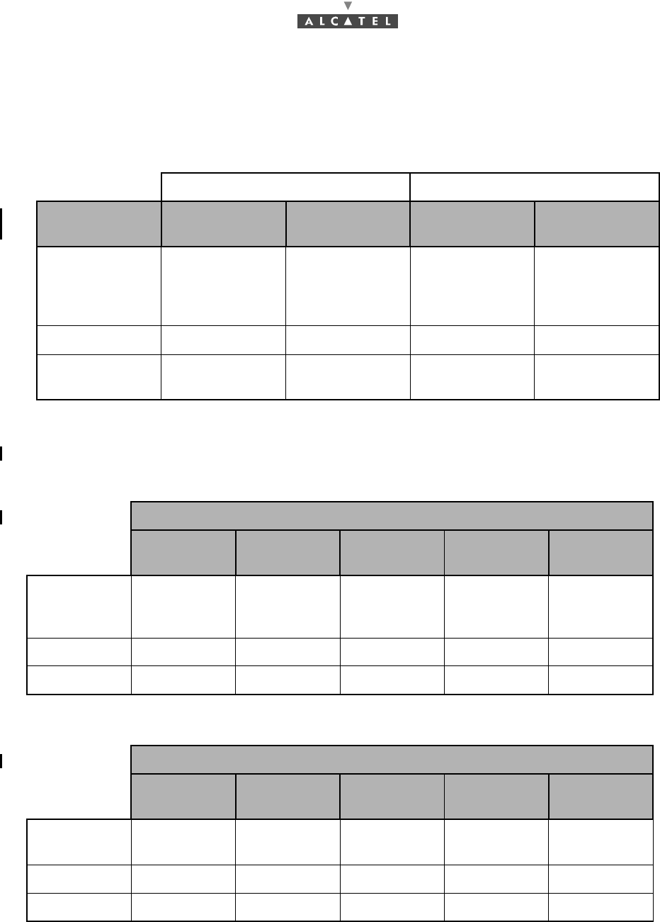
2.6.1 RT specifications
2.6.2 NT specifications
2.6.2.1 NT units
There are eight types of NT units:
RT NT
Designation With antenna
26 cm Antenna
60 cm Description Observations
Dimensions
HxLxP 200 x 200 (mm)
x 50 (mm)
antenna
diameter: 60 cm
cf. diagram in
Appendix 6
1U x 19"
x 240 (mm) cf. diagram
in § 3 Installation
Weight 2 kg 12 kg 3 kg —
Operating
temperature – 33°C to + 55°C– 45°C + 55°C– 5°C to + 55°C—
NT units
9900 NCA
001 9900 NGA
001 9900 NGA
004 9900 NCA
002 9900 NCB
001
Telephony,
leased lines 2 x E1
(2 x G703) 2 x E1
(2 x G703)
2 x E1
(2 x G703)
LEMO
2 x E1
(G703 + X21) 4ISDN
2B1Q-60V
Data 2 x Eth 10bT 2 x Eth 10bT 2 x Eth 10bT 2 x Eth 10bT 2 x Eth 10bT
Supply 85 - 264 V "18 - 60 V $18 - 60 V $85 - 264 V "85 - 264 V "
NT units
9900 NGB
001 9900 NCD
001 9900 NCE
001 9900 NCB
002 9900 NGB
002
Telephony,
leased lines 4ISDN
2B1Q–60V 2xT1
ANSI 4ISDN
4B3T–60V 4ISDN
4B3T–60V
Data 2 x Eth 10bT 2 x Eth 10bT 2 x Eth 10bT 2 x Eth 10bT 2 x Eth 10bT
Supply 18 – 60 V $85 – 264 V "85 – 264 V "85 – 264 V "18 – 60 V $
3CC12423AAAA TQ BJA 01 Issue 01 - March 2001 - Draft 03 23/ 114
24
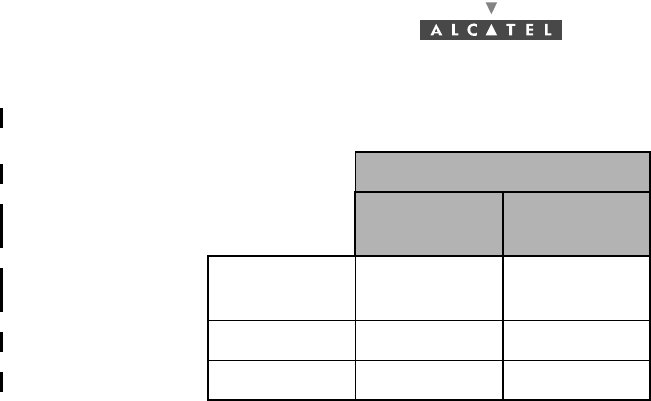
2.6.2.2 NT Lite units
2.7 Equipment power consumption
The typical power consumption of the RT is 13 W.
The maximal power consumption of an NT is 71 VA.
NT Lite units
9900 NCF
001 9900 NCG
001
Telephony,
leased lines 1x E1 (G703) 1x T1 (G703)
Data 1 x Eth 10bT 1 x Eth 10bT
Supply 85 – 264 V "85 – 264 V "

24/ 114 Issue 01 - March 2001 - Draft 03 3CC12423AAAA TQ BJA 01
24
PAGE INTENTIONALLY LEFT BLANK
3CC12423AAAA TQ BJA 01 Issue 01 - March 2001 - Draft 03 25/ 114
52
3 Installation of the 7390TS Terminal Station
3.1 Equipment delivery
When you receive the equipment in its packaging:
–Check the condition of the packaging.
–If damaged, make your reservations known to the carrier without delay.
3.1.1 Unpacking
Considerations
You are recommended to:
–unpack the equipment according to the instructions on the packaging, and to the instructions given
below.
–take an inventory and identify any missing items. If the delivery does not match the delivery advice
note, notify ALCATEL within 48 hours of receipt of the equipment.
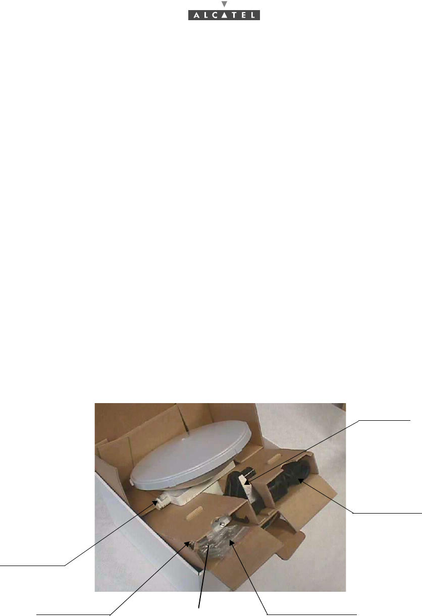
Stages for integrated
1. Open the cover flap of the package lid (Figure 4 – Unpacking the RT unit with integrated antenna).
2. Remove the cardboard packing wedge protecting the box’s contents.
3. Remove the RT unit, taking care not to damage the antenna.
4. Remove the slotted casing from the box.
5. Remove the packaged items fixed in the slots of the casing.
6. Detach the drilling template if wall-mounting is to take place.
Figure 4 – Unpacking the RT unit with integrated antenna
In case RT provided has «F» connectors, the connector provided is the plastic bag (1) is a «F» type-
connector and the polarisation kit (2) is not provided because it is useless with the type of RT
(see § 3.4 )
radio unit
and antenna
wall mount
bearing mount
polarization kit
mounting kit (
2)
"N" connector and
attachment hardware
(1)