Alcatel Canada 24T07A01D22D 7390 24 GHz Co-Pol RT User Manual NT Manual pages 26 to 35
Alcatel Canada Inc 7390 24 GHz Co-Pol RT NT Manual pages 26 to 35
Contents
NT Manual pages 26 to 35
26/ 114 Issue 01 - March 2001 - Draft 03 3CC12423AAAA TQ BJA 01
52
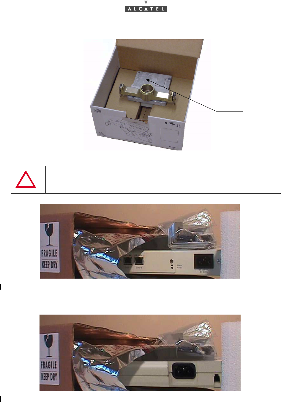
Figure 5 – Unpacking the adaptator for a non-integrated antenna
Figure 6 – Unpacking the NT unit
The NT unit equipment is protected by safety cover. Do not unpack the equipment in advance if it is not
to be installed immediately.
Figure 7 – Unpacking the NT Lite unit
IMPORTANT NOTE: NEVER REMOVE THE ROUND YELLOW PADS, VISIBLE
AT THE ANTENNA ACCESS, USED TO SEAL THE OUTDOOR SYSTEM.
adaptator adaptator
3CC12423AAAA TQ BJA 01 Issue 01 - March 2001 - Draft 03 27/ 114
52
3.1.2 Checking the configuration
The Terminal Station components delivered are:
–the RT unit (also called RT or RT radio) and its installation accessories are in one box for inte-
grated antenna. For non integrated antenna, there are three boxes: RT radio, antenna and pole
mounting.
–the NT unit (also called NT) and its installation accessories are in another box.
Depending on the site configurations, the delivery will include individual boxes containing:
–one or more passive or active splitter modules.
–one or more repeater modules.
3.1.2.1 Content of boxes
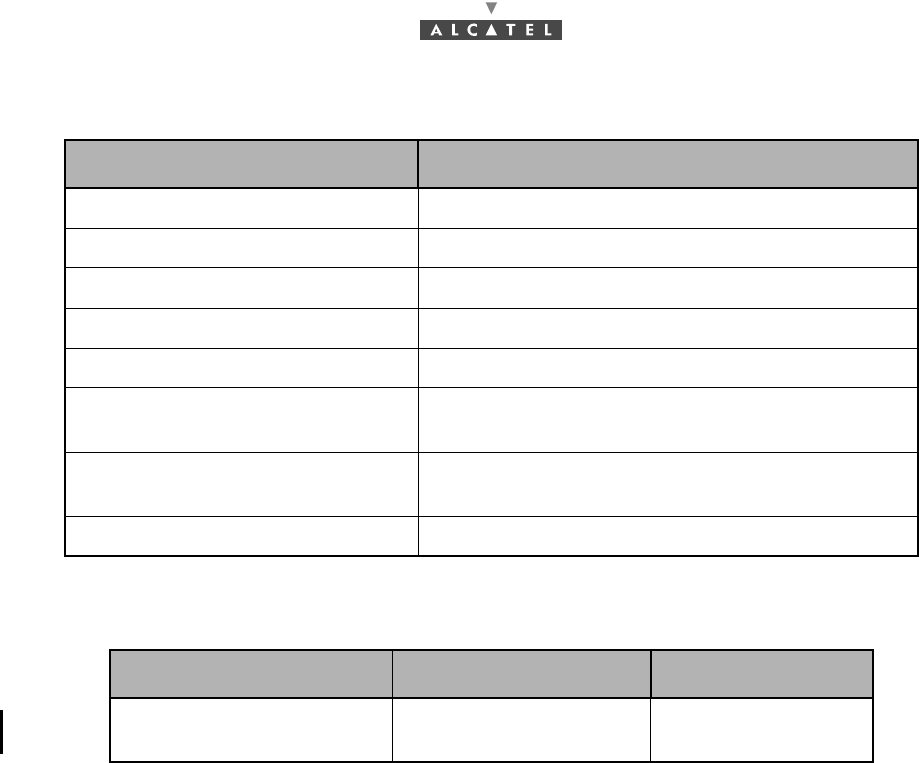
For integrated antenna
For non integrated antenna
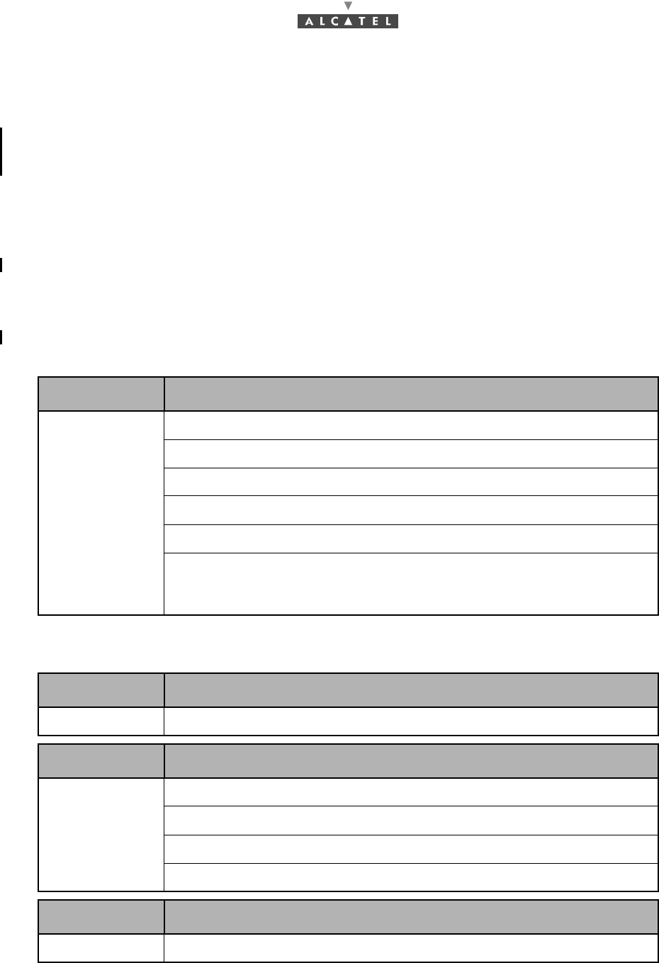
EQUIPMENT CONTENTS
RT UNIT
1 RT with antenna mounted assembly
1 wall mount
1 bearing mount
1 horizontal polarisation kit with screw accessories
2 U bolts
1 bag containing 1 type "N" 75 ohm connector, four M6x50 screws with
washers and plugs; four M8 nuts with washers, 2 terminal lugs and one
M6x20 screw with washers
EQUIPMENT CONTENTS
RT UNIT 1 RT with adaptation for mounting a 600 mm diameter antenna
EQUIPMENT CONTENTS
RT UNIT
1 Pole mounting including 2 fine alignments for antenna
2 U bolts
Pole mounting 1 bag containing 7 M6x16 screws with washers
5 crimp terminals, 1 M6 nut and 2 washers
EQUIPMENT CONTENTS
Antenna 600 mm diameter antenna
28/ 114 Issue 01 - March 2001 - Draft 03 3CC12423AAAA TQ BJA 01
52
In any case
3.1.2.2 Storage
If installation is to be deferred, the type of packaging defines the equipment storage conditions:
–cardboard boxes should be warehoused indoors, in a well-ventilated and dry room ,
–wooden or polywood boxes may be stored outdoors, provided that they are protected from rain
and direct sunlight.
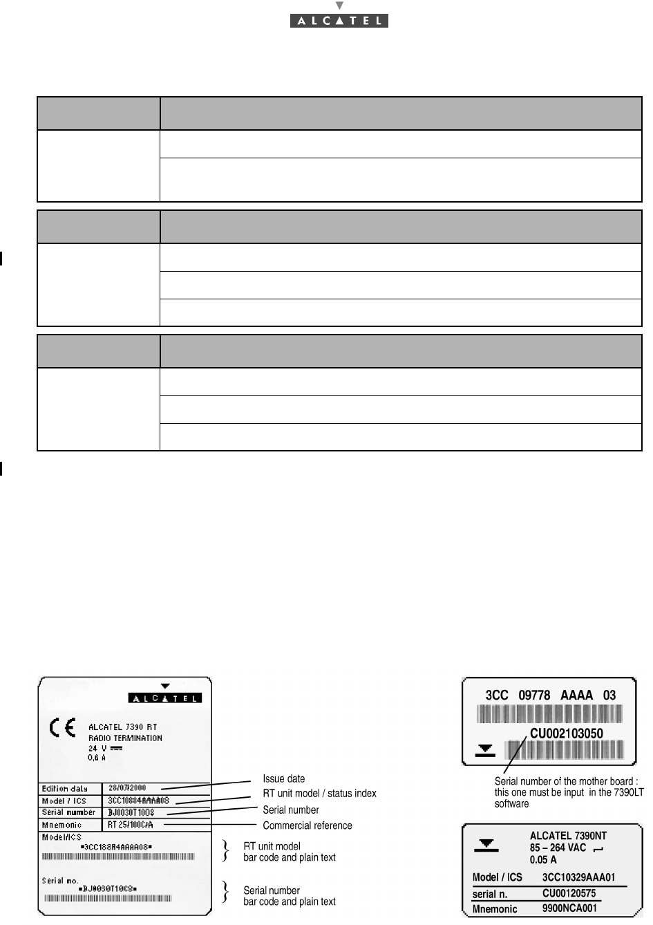
3.2 Labels on the equipment
The labels below are affixed to the equipment and their cardboard boxes to indicate the contents.
Figures given on the examples below are not contractual.
EQUIPMENT CONTENTS
NT UNIT
1 Indoor Unit
1 installation kit containing feet, bracket mouting, handles, attachment
accessories and 1 "F" connector
EQUIPMENT CONTENTS
Splitter kit
1 splitter passive module
1 bag containing screw accessories
W3 connectors F and one 75 Ω load
EQUIPMENT CONTENTS
Repeater kit
1 repeater module
1 bag containing screw accessories
2 connectors "F"
Figure 8 – Packaging of the RT unit Figure 9 – Packagings of the NT unit
3CC12423AAAA TQ BJA 01 Issue 01 - March 2001 - Draft 03 29/ 114
52
3.3 Installing the equipment
It is recommended that all peripheral equipment (e.g., repeaters, splitters) as well as the engineering
accessories should be installed before installation of the Terminal Station.
3.3.1 Information required for installation
Appendix 1 – 7390 TS installation sheet contains a sheet for you to complete and collect all the
general information needed for the installation procedure.
3.3.2 Precautions concerning electromagnetic compatibility
Installation is designed to meet all new requirements concerning electromagnetic compatibility and
safety.
The performance of the equipment depends on installation practices (cable installation, ground
connections, etc.) which should be based on best trade practices and which may be degraded if these
practices are not respected.
3.3.3 Tools required
The installation staff must possess a standard installation toolkit (containing, in particular: drill, drill bits,
soldering iron, cable tie pliers, terminal pliers). A heating pack is also required for heat-shrinking
operations.
The list of tools required for the mechanical installation of the Terminal Station is given below:
FOR INTEGRATED ANTENNA
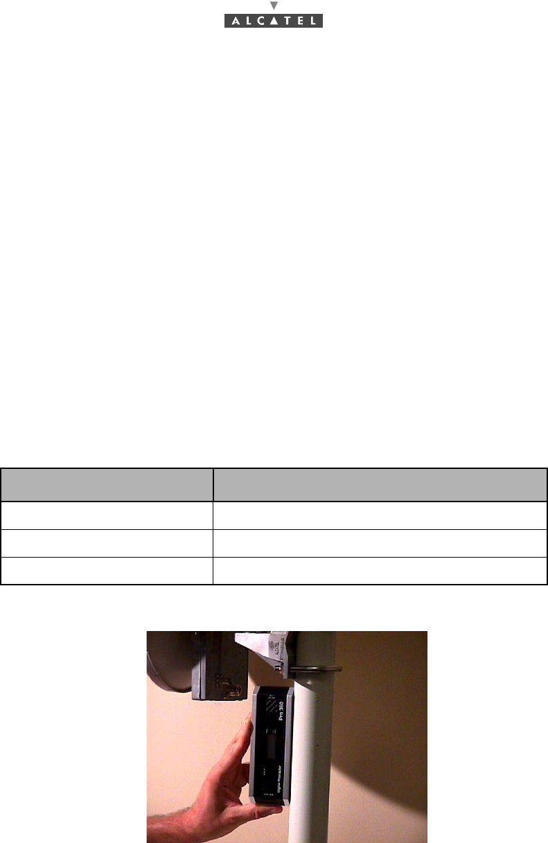
Figure 10 – - Inclinometer
Tool Use
5 mm Allen key (for M6 screw) For securing the pole mounting and wall mounting
13 wrench For tightening the U bolts on the 40 to 50 mm tube
Level gauge or inclinometer For vertically of the bearing axis
30/ 114 Issue 01 - March 2001 - Draft 03 3CC12423AAAA TQ BJA 01
52
FOR NON INTEGRATED ANTENNA
Depending on the installations, additional equipment, provided by Alcatel as optional, may prove useful:
To get the commercial codes of these items, please consult Appendix 5 – Correspondence between
commercial codes and industrial codes relating to the TS which gives the connection between industrial
and commercial codes.
A compass and a pair of binoculars (not supplied) are useful for rough prepointing of the antenna.
The use of a torque wrench is recommended.
Tool Use
2.5 mm Allen key (for M3 screw) For adjusting the polarization of the antenna
3 mm Allen key (for M4 screw) For adjusting the polarization of the antenna
5 mm Allen key (for M6 screw) For mounting the antenna
8 mm Allen key (for M10 screw) For tightening the different parts of the pole mounting
10 mm Flat wrench For fixing the ground terminal
16/17 mm box wrench and flatwrench For fixing the "pole mounting" and fine tuning the
antenna and various fastenings
16/17 mm torque wrench For fixing the pole mounting and various fastening
with the correct torque
20 mm Flat wrench For fitting the "N" coaxial plugs
Tool Use Industrial Code
E-RIT and NT installation tool
kit cables and software E-RIT installation 9900YTA001
3CC12423AAAA TQ BJA 01 Issue 01 - March 2001 - Draft 03 31/ 114
52
3.4 Installation of the Terminal Station RT unit with an inte-
grated antenna
Considerations:
The installation of the RT unit should satisfy the following criteria:
–unimpeded direct line of sight between RT unit and RBS (Base Station),
–perfect mechanical rigidity,
–enabling precise antenna alignment.
The 7390RT is designed for outdoor installation without any particular protection. However, the following
recommendations must be respected:
–do not install equipment below bird nesting areas,
–do not attach equipment to a surface prone to vibrations (machinery, lift housing, air conditioning,
etc.),
–do not attach equipment to chimneys which give off fat deposits, dust and other aerosols which
are liable to come to rest on the equipment,
–do not install equipment in proximity of sources of heat,
–do not place the equipment in proximity to corrosive gas outputs,
–do not place the equipment below roof run-offs not equipped with guttering (high risk of microwave
short-circuit),
–do not install at man-height to prevent human collisions against the antenna. This could cut the
radio link with the central station.
Two types of assembly are possible:
–on a flat, vertical surface (e.g., a wall),
–on a pole/tube (existing or to be installed), using threaded U-bolts and nuts (M8).
Note: The pole/tube selected should be sufficiently rigid to prevent antenna misalignment and resist
vibrations.
Use tube supports that comply with our recommendations. Support references are mentioned in
the next chapters.
3.4.1 Definition of assemblies with respect to chosen polarization
The Terminal Station RT unit can be mounted with horizontal (H) or vertical (V) polarization.
To mount the radio/antenna assembly on the support arm, in the event of horizontal polarization, the
horizontal polarization kit must be used. This consists of an additional joint to compensate for the
mechanical rotation of the system.
IMPORTANT NOTE: NEVER HANDLE THE RT UNIT BY ITS ANTENNA BUT BY
THE BODY OF THE RADIO OR THE SUPPORT ARM
USE THE SAME POLARIZATION ON TERMINAL STATION AND BASE STATION

32/ 114 Issue 01 - March 2001 - Draft 03 3CC12423AAAA TQ BJA 01
52
The pole-mounting mechanical assembly consists of (Figure 11 – Support arm components):
–two components in the case of vertical polarization (V): wall mounting (ref.1) and bearing moun-
ting (ref.2);
–three components in the case of horizontal polarization (H): wall mounting (ref.1) , bearing moun-
ting (ref.2) and polarization mounting (ref.3).
Figure 11 – Support arm components
A polarization slot indicator at the rear of the RT unit can be checked to confirm that the assembly is
correct with respect to the chosen polarization:
–if the letter "H" can be read naturally, polarization is horizontal,
–if the letter "V" can be read naturally, polarization is vertical,
Figure 12 – Vertical Polarization
Figure 13 – Horizontal polarization
123
bearing mount
wall mount
horizontal polarization
mount
only with
the RT cube
vertical axis
vertical axis
vertical axis
3CC12423AAAA TQ BJA 01 Issue 01 - March 2001 - Draft 03 33/ 114
52
3.4.2 Installation of the 7390 RT on a wall or flat vertical surface
Considerations:
–If attaching the RT unit using bolts and plugs, select the attachment components to suit the com-
position of the attachment surface.
–The surface chosen should not be prone to vibrations (e.g., avoid machine housings).
–To mark the drill holes, use the drilling template printed on the inside panel of the RT unit packa-
ging box.
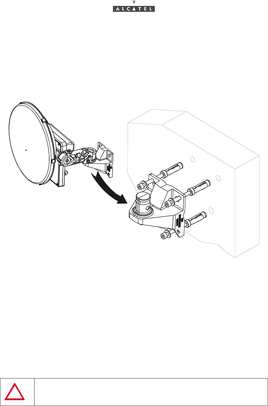
Figure 14 – Installation of the RT unit on a wall
Stages
1. Select the installation location and determine the polarization of the RT unit.
2. Place the drilling template against the wall (or surface) to be pierced.
Note: The vertical axis of the wall mounting assembly must be respected (see Figure 15 – Wall moun-
ting). Used a bubble level or inclinometer.
3. Drill the 4 holes.
4. Insert the 4 plugs.
5. Install and secure the wall mounting (V et H polarization) using four M6x50 screws with washers.
Note: Screw torque = 4.3 to 4.9 m.N.
IMPORTANT: VERTICALITY OF ± 1° REQUIRED FOR POLARIZATION
34/ 114 Issue 01 - March 2001 - Draft 03 3CC12423AAAA TQ BJA 01
52
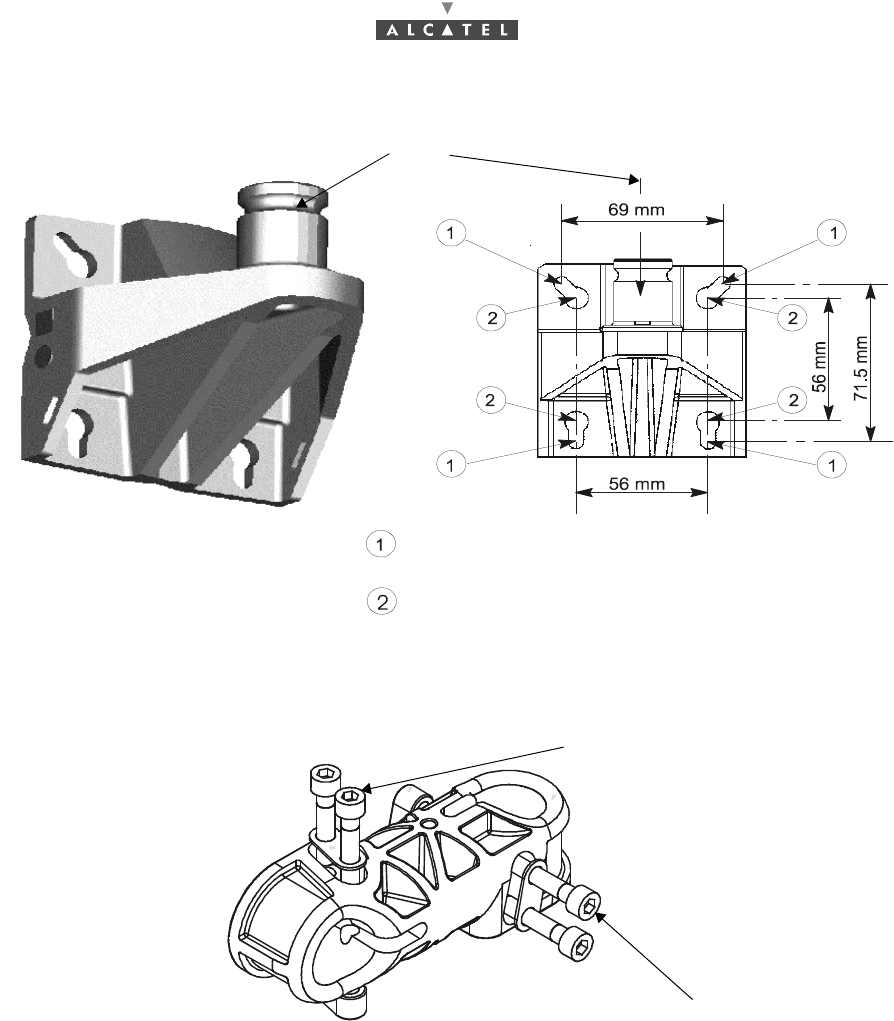
Figure 15 – Wall mounting
6. Install and secure the bearing mounting on the wall mounting (V and H polarization).
Figure 16 – Screws mounting
To continue the hardware installation, go to step 7 in the case of horizontal polarization or go directly to
step 8 for vertical polarization.
7. Install and secure the polarization mounting (H polarization only).
8. Install and secure the RT unit on the support arm. Check on polarization indicator that the
polarization assembly is correct (cf. Figure 12 – Vertical Polarization and Figure 13 – Horizontal
polarization).
9. Release the RT assembly locking screw and carry out antenna prepointing visually and/or using a
compass and a map. To do this, orientate the assembly so that the antenna is pointed towards the
Base Station antenna.
10. Remove the radio module from its axis for configuration (see Chapter 4 Commissioning the 7390 TS
Terminal Station).
assembly must be respected.
Use elongated holes dia. 6.5 mm for wall mounting
(plugs and M6 screws with washers).
Use holes dia. 10 mm for 50 mm tube mounting
(U-bolts and M8 nuts)
This screw is installed on site
This screw is installed
on site
The vertical axis of the wall mounting
3CC12423AAAA TQ BJA 01 Issue 01 - March 2001 - Draft 03 35/ 114
52
3.4.3 Installation of the RT unit on a tube for «N» or «F» connector RT
Considerations
–Install on tube using two U-bolts.
–Installation may be carried out on a newly installed or existing tube.
–The external diameter of the tube is 76 mm in standard configuration.
–The support tube, along with the U-bolts, must be clean and (apart from threads) grease-free.
–If specific site features make perfect alignment impossible (line of sight parallel to the wall, for
example). You are recommended to use a support that complies with our specifications (see re-
ferences in the paragraphs which follow).
Note: The use of supports with slenderness ratios inferior to our own is authorized (more rigid).
Note: Slenderness ratio = length / cross-section of sections used.
Steps
1. Select the installation location and determine the polarization of the RT.
2. Install and secure the wall mounting (V et H polarization) using the two U-bolts (and nuts with
washers) provided for this purpose, or the attachment hardware delivered with the specific wall
mount.
Note: Screw torque = 10.5 to 12 m.N.
Note: The vertical axis of the wall mounting assembly must be respected.
3. Install and secure the bearing mounting on the wall mounting (V and H polarization), see Figure 11
– Support arm components.
To continue the hardware installation, go to step 4 in the case of horizontal polarization or go directly to
step 5 for vertical polarization.
4. Install and secure the polarization mounting (H polarization only).
5. Install and secure the RT radio unit with its antenna on the support arm. Check the polarization
indicator to check correct polarization (cf. Figure 12 – Vertical Polarization and Figure 13 – Horizontal
polarization).
6. Release the RT assembly locking screw and carry out antenna prepointing visually and/or using a
compass and a map. To do this, orientate the assembly so that the antenna is pointed towards the
Base Station antenna.
7. Remove the radio module from its axis for configuration (See Chapter 4 Commissioning the 7390 TS
Terminal Station) to make commissioning easier.
IMPORTANT: VERTICALITY OF ± 1° REQUIRED FOR POLARIZATION
IMPORTANT NOTE: THE USE OF SUPPORTS WITH A SLENDERNESS RATIO
GREATER THAN OUR MODELS SHOULD BE EXCLUDED (TOO FLEXIBLE)