Alcatel Canada 24T07A01D22D 7390 24 GHz Co-Pol RT User Manual NT Manual pages 36 to 50
Alcatel Canada Inc 7390 24 GHz Co-Pol RT NT Manual pages 36 to 50
Contents
NT Manual pages 36 to 50
36/ 114 Issue 01 - March 2001 - Draft 03 3CC12423AAAA TQ BJA 01
52
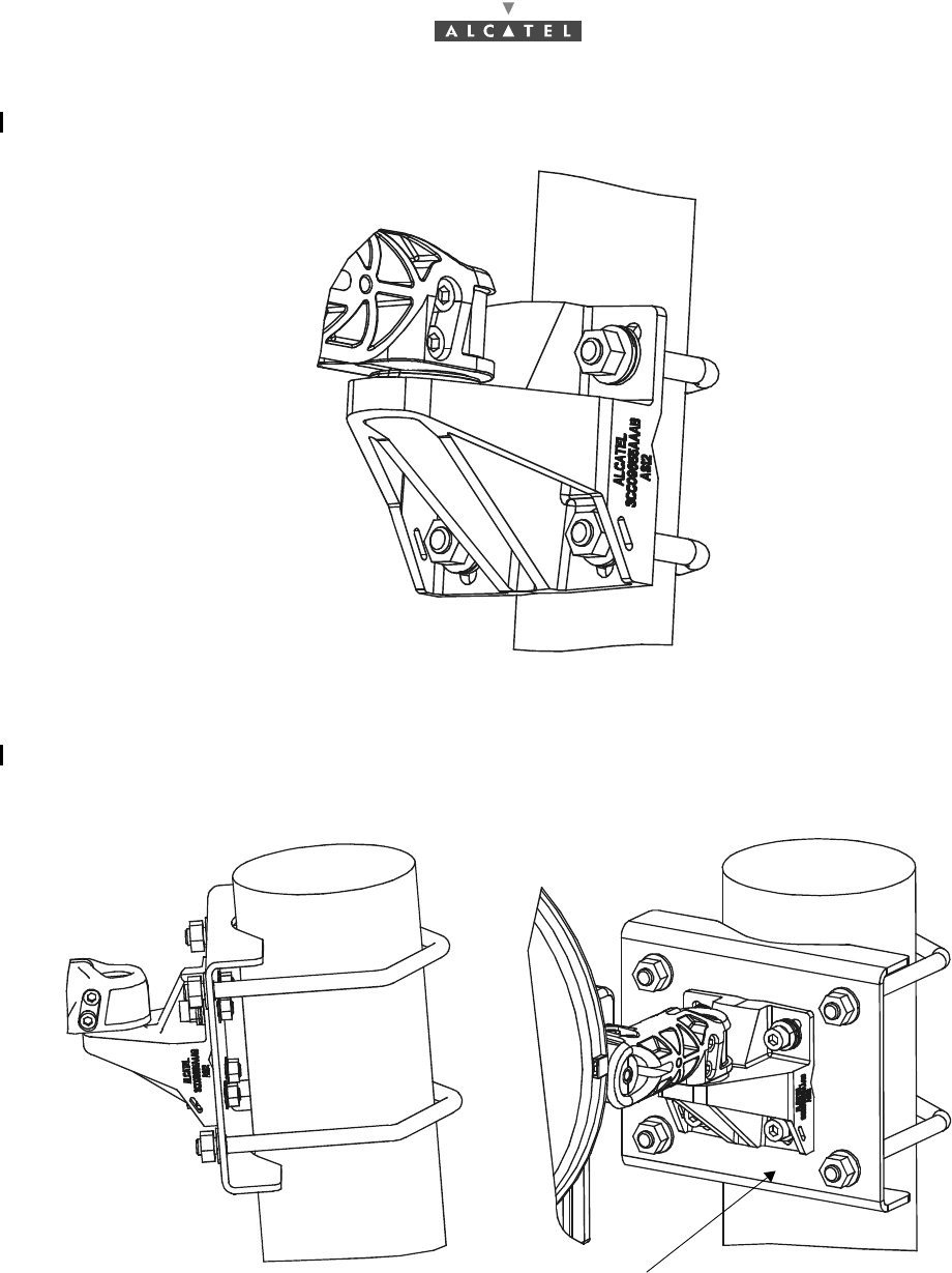
3.4.3.1 Installing the RT unit on an existing tube, 76 mm in diameter
Figure 17 – Installing the RT unit on an existing tube, 76 mm in diameter
3.4.3.2 Installing the RT unit on an existing tube, 76 to 114 mm in diameter
Use the 3CC10802 Axxx kit.
Figure 18 – Installing the RT on a tube, 76 to 114 mm in diameter
Kit 3CC10802Axxx
3CC12423AAAA TQ BJA 01 Issue 01 - March 2001 - Draft 03 37/ 114
52
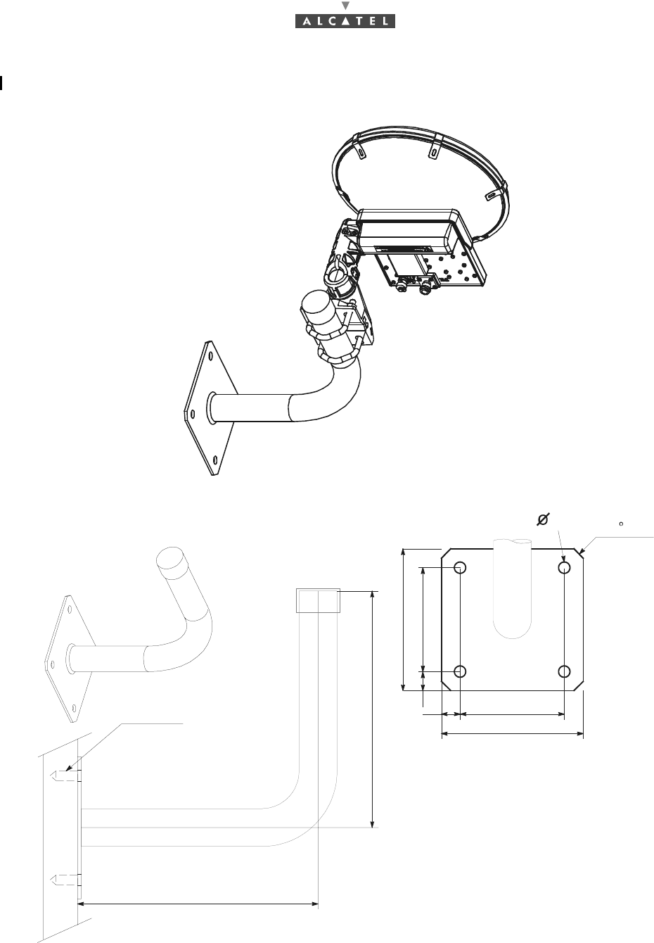
3.4.3.3 Front installation of the RT unit
Use a support in accordance with our 3CC11132Axxx model.
Figure 19 – Topview of RT front installation
Figure 20 – Quotation of the RT in frontage
150
11020
150
11020
12 45 x 10
250
250
SPIT M8
38/ 114 Issue 01 - March 2001 - Draft 03 3CC12423AAAA TQ BJA 01
52
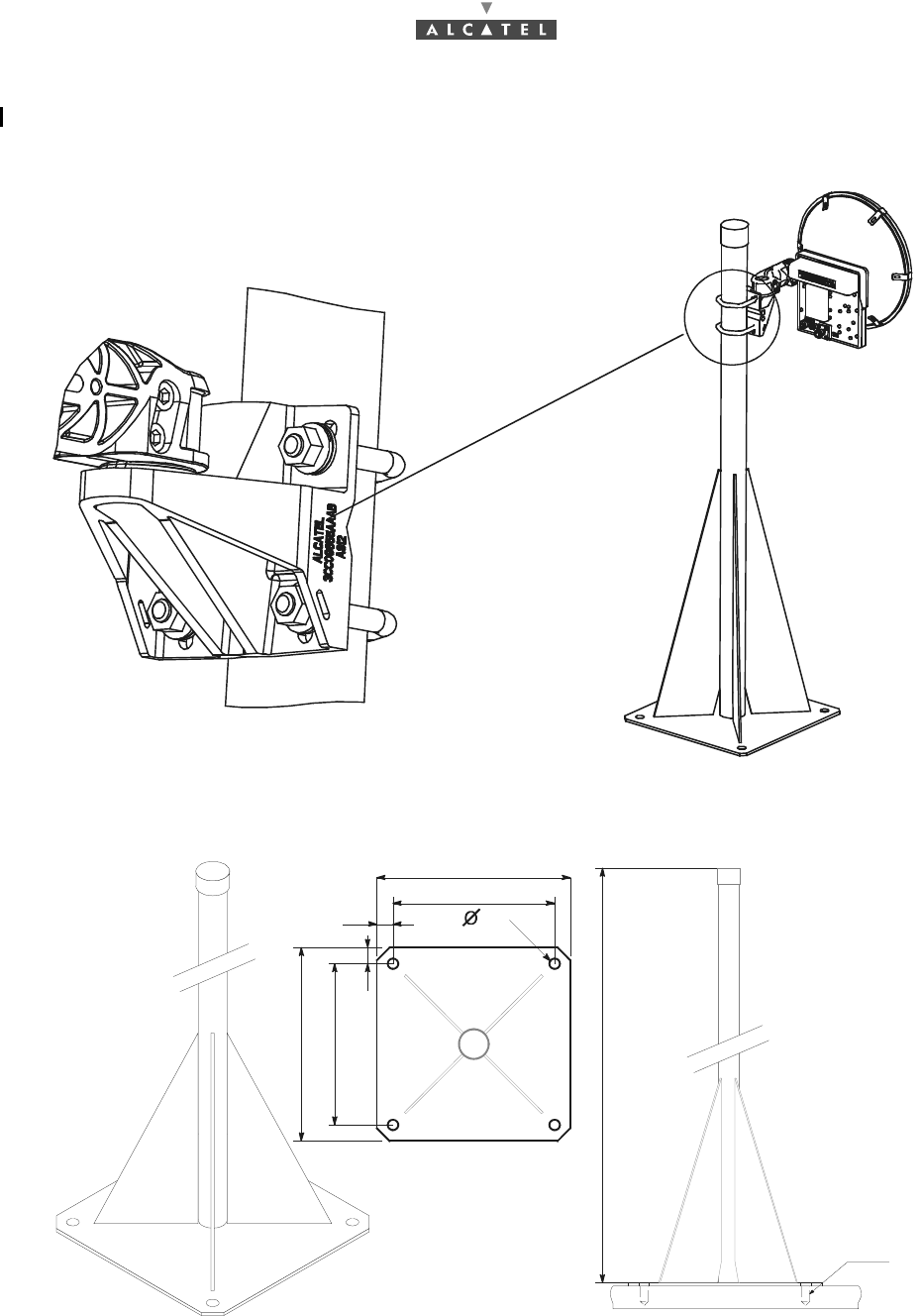
3.4.3.4 Rooftop mounting of the RT unit (raised), 1 meter mast
Use a support in accordance with our 3CC11133Axxx model.
Figure 21 – Rooftop mounting of the RT unit (raised), 1 meter mast
Figure 22 – Quotation of the rooftop mounting of the RT unit, 1 meter mast
Fixation detail
1000
SPIT M12
250
300
25
250
25
300
16
3CC12423AAAA TQ BJA 01 Issue 01 - March 2001 - Draft 03 39/ 114
52
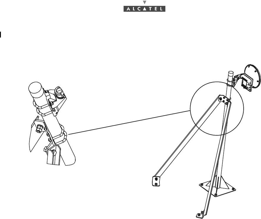
3.4.3.5 Rooftop mounting of the RT unit (raised), 1.5 meter mast
Use a support in accordance with our 3CC11134Axxx model.
Figure 23 – Rooftop mounting of the RT unit (raised), 1.5 meter mast

40/ 114 Issue 01 - March 2001 - Draft 03 3CC12423AAAA TQ BJA 01
52
Figure 24 – Quotation of the rooftop mounting of the RT unit, 1.5 meter mast
1500
SPIT M1
250
300
250
300
16
260
450
3CC12423AAAA TQ BJA 01 Issue 01 - March 2001 - Draft 03 41/ 114
52
3.4.4 Grounding the RT unit
Considerations
–It is not necessary to establish special grounding connection for the RT casing. However the RT
unit can be grounded.
–On the RT unit, the ground terminal is in the form of a tapped hole (see Figure 25 – Grounding the
RT unit) on the attachment axis of the pole mounting.
–The RT unit can be grounded using the grounding lug and screw hardware supplied with the equi-
pment.
Steps
1. Crimp a lug (ref.: 16-6 CT) on to the grounding cable (16 mm 2 minimum cross-section).
2. Screw the cable lug into the tapped hole. Use an M6 screw and onduflex washers.
Figure 25 – Grounding the RT unit
Note: Position of the grounding screw may differ according to mechanical variants beeing either close
to the 75 ohm connector or on the side as shown here.
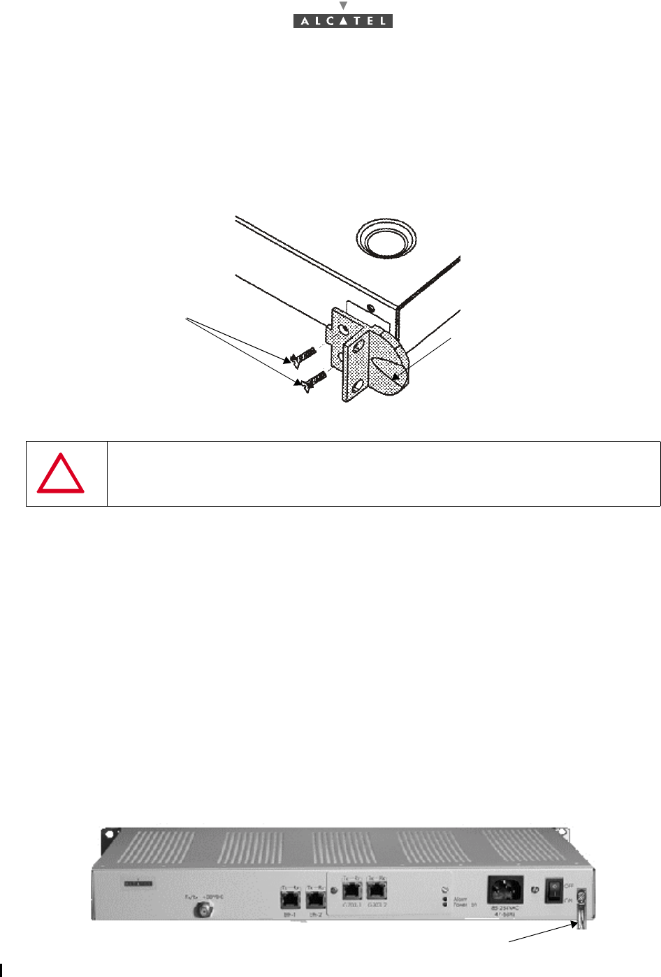
grounding screw
42/ 114 Issue 01 - March 2001 - Draft 03 3CC12423AAAA TQ BJA 01
52
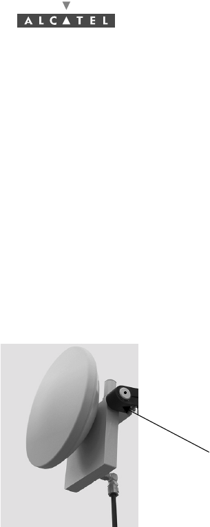
3.5 Installation of the Terminal Station RT unit with a non
integrated antenna
See Appendix 6 – Installation of the Terminal Station RT unit with a non integrated antenna.
3.6 Installation of the RT/NT link
Considerations
–The electrical connection between the RT unit and the NT unit of the Terminal Station is made
using a type ET 2PA 981 75 ohm coaxial cable equipped with "F" connectors (at the NT side end)
and "N" connectors (at the RT side end).
–If a single cable (70 meters without connectors) does not cover the distance between the RT unit
and the NT unit, up to two repeaters must be used. For the possible configurations and installation
of a repeater, see § 3.8 .
–If the RT unit is connected to several NTs of the Terminal Station, use several splitters. For the
possible configurations, and installation of a splitter, see § 3.9 Installation of one or several repea-
ters with splitter(s).
–The length of the cable used must be noted. In order to facilitate this measurement, refer to the
markings printed every meter, on the outer sheath of the cables. To know the length of cable ins-
talled, subtract the number at one end from the number at the other end of the cable used. Note
the result at the NT side end.
–You are recommended to secure the coaxial cable every meter with a cable tie. Use collars fitted
to the support used for the path.
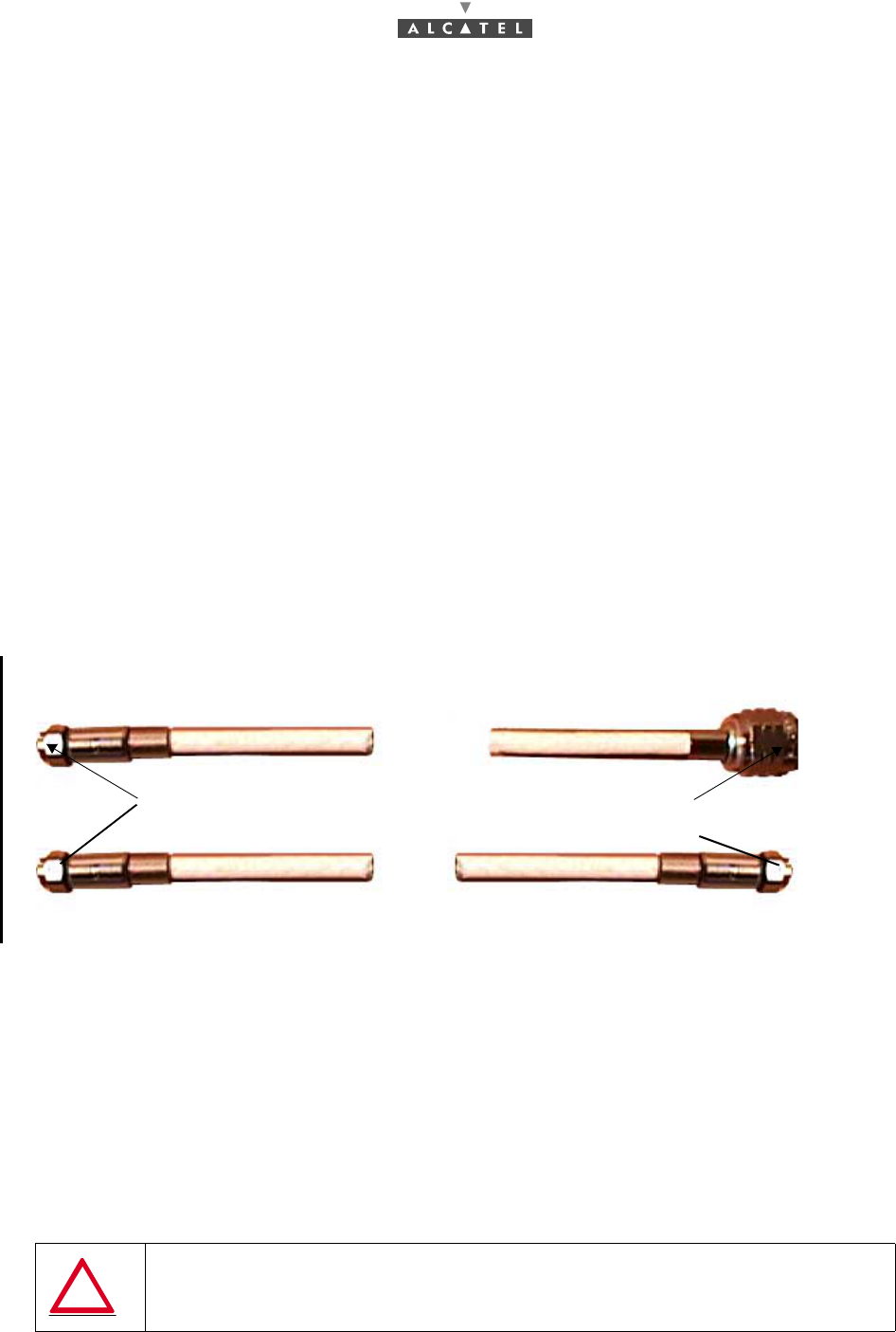
Figure 26 – Coaxial cable
–Physical cable characteristics are:
•diameter = 7.5 mm,
•maximum installed cable length = 210 meters,
•minimal bend radius = 40 mm or 100 mm for a "drip of water".
Steps
1. Carry out the 75 ohm connector between the RT unit and the NT unit.
Note: In the event of the use of repeaters and/or splitters, use the number of cables required by the
configuration. Refer to § and § 3.9 Installation of one or several repeaters with splitter(s).
Note: Make a drip groove where the cable enters the building, respecting the cable's bending radius
(100 mm minimum), in order to prevent water infiltration.
AVOID A TOO LONG PARALLEL WALK BETWEEN THE RT/NT COAXIAL LINK
AND ELEC-TRICAL CABLES, OR GSM/DCS BASE STATION CABLES
"F" connector 75 Ω " N" connector
To NT unit
To RT unit
To RT unit
"F" connector
3CC12423AAAA TQ BJA 01 Issue 01 - March 2001 - Draft 03 43/ 114
52
2. Note the length of the cable installed in the 7390 RT/NT cabling sheet (Appendix 1 – 7390 TS
installation sheet). This information will be entered into the database when the equipment is
commissioned using the configuration software.
Note: The accuracy required by the configuration software is ± 1.5 m.
3. At the RT unit side end, equip the cable with a type "N" 75 ohm coaxial connector if RT «N» and «F»
with RT «F», supplied with the equipment. For attaching the coaxial terminals, refer to the
manufacturer's Assembly manual and use the specific tools as recommended. One of the main
causes of installation problems is the faulty mounting of connectors.
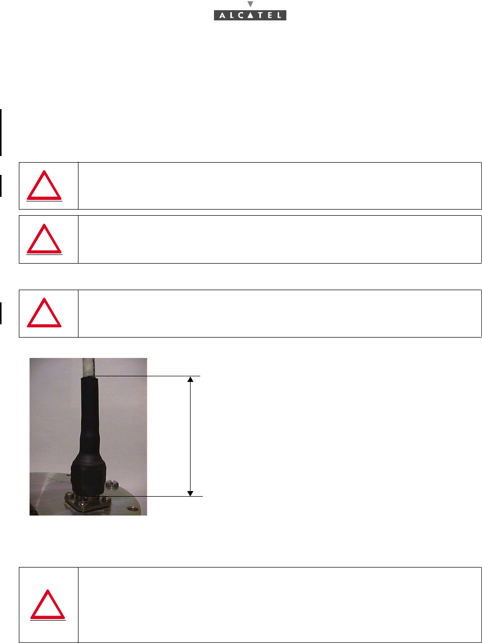
Figure 27 – Connecting the "N" connector with the thermoshrinkable sleeve
4. Attach the cable to the RT unit using a cable tie.
Note: No overtighten the cable tie on the cable; this could cause deformation of the dielectric and sub-
sequent loss of performance.
5. Run the cable to the NT unit and equip it with a type "F" 75 ohm coaxial connector, supplied with the
equipment.
NEVER USE 50 OHM CONNECTORS, AT THE RISK OF DESTROYING THE RADIO
UNIT, USE ONLY THE N 75 CONNECTOR SUPPLIED IN THE RT BOX (FOR RT «N»)
IMPORTANT NOTE: NEVER HANDLE THE RT UNIT BY ITS ANTENNA
BUT BY THE BODY OF THE RADIO OR THE SUPPORT ARM
IMPERATIVE : PROTECT THE "N" CONNECTOR OR «F» CONNECTOR
CONNECTION WITH A PRE-PASTED THERMOSHRINKABLE SLEEVE
THE COAXIAL CABLE SHOULD NEVER BE TOO TIGHT BETWEEN THE RT AND
ITS MOUNTING. ADJUST THE POSITION OF THE MOUNTING AND THE LENGHT
OF THE CABLE TO SUIT, OTHERWISE THERE IS A MAJOR RISK OF ANTENNA
MISALIGMENT OR CABLE DAMAGE AT THE CONNECTOR. ON THE OTHER
HAND, TOO SLACK A CONNECTION CAN HAVE THE SAME CONSEQUENCES
UNDER THE EFFECT TO THE WIND
70
Thermoshrink a pre-pasted sleeve on the
connector/terminal/cable assembly 70 mm
along. (80 mm minimum long before thermoshrink).
The sleeve end should stop at the terminal base.
44/ 114 Issue 01 - March 2001 - Draft 03 3CC12423AAAA TQ BJA 01
52
3.7 Installation of the Terminal Station 7390 NT (Indoor
Unit)
Considerations
–The NT units are intended for indoor installation only.
–The NT should be positioned in accordance with the needs of the user and the technical cons-
traints (e.g., minimum distances to be respected, topology of the connections, accessibility of the
RT/NT link, power supply).
–Always place the NT nit in a dry, dust-free environment, away from any major source of heat
(-5°C<T<+55°C).
–Always place the NCAxxx NT unit near a rated power source: 85-264 VAC , 47-63 Hz with ground
connection.
Note: Use grounded power connections only. Avoid the use of extension cables.
–The NT to sector connection must be done last, during commissioning (see Chapter 4 Commis-
sioning the 7390 TS Terminal Station), TS installation, included all other connections, being com-
pleted.
–Do not install the NT too close to the ground (keep at a distance from dust and floor cleaning pro-
ducts).
–Do not install on premises containing corrosive materials.
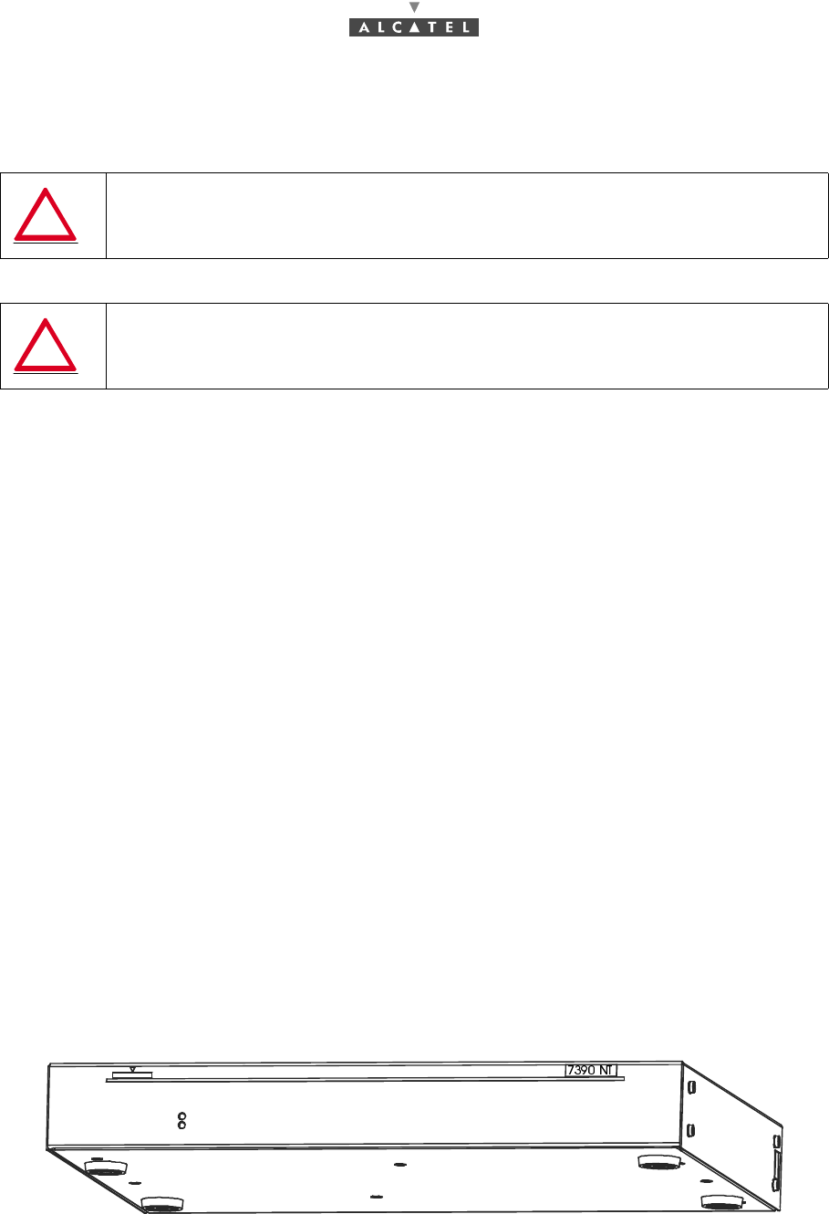
3.7.1 Installation of the 7390NT unit on a desktop
Steps
1. After unpacking the unit, fit it with its four feet, clipping them on to the bottom of the unit.
2. Connect the NT unit to the Terminal Station RT ("F" connector).
Figure 28 – Mounting the feet
A SPACE OF 1U (in the event of rack mounting) OR APPROXIMATELY 50 mm
MUST BE LEFT FREE ABOVE THE TERMINAL STATION IDU
NEVER STORE DOCUMENTATION OR ANY OTHER OBJECTS ABOVE THE NT
UNIT ON THE VENTILATION HOLES. THIS MAY CAUSE IT TO BE DAMAGED
3CC12423AAAA TQ BJA 01 Issue 01 - March 2001 - Draft 03 45/ 114
52
3.7.2 Installation of the NT unit on a 19" rack
Steps
1. Fit the rack adaptators on the NT unit (see Figure 29 – Fitting the NT unit rack adaptators).
2. Install the unit in the 19" (or other type) rack (screw fittings not included, depending on the
manufacturer).
3. Connect the NT to the RT ("F" connector).
Figure 29 – Fitting the NT unit rack adaptators
3.7.3 Earthing the NT units
Considerations
–NT casing must imperatively be connected to the main earth with a cable 16 mm2 minimal cross-
section whose length must not exceed 2.40 m. The grounding terminal is on the right of the NT
unit (connections side) and is in the form of a tapped hole (see Figure 30 – Earthing the (NCAxxx)
NT unit).
–The earth connection should be made as directly as possible between the unit and the general
earthing system of the side (bar, rod, plate, etc.).
–The grounding of the NCAxxx NT units is through the 220V main connector; for the NGAxxx units,
only one earthing point is necessary, after the earthing of all the NT units.
Steps
1. Crimp a lug (ref.: 16-6 CT) on to the earthing cable (16 mm2 cross-section).
2. Screw the cable lug into the terminal designed for this purpose. Use an M6 screw.
Figure 30 – Earthing the (NCAxxx) NT unit
A SPACE OF AT LEAST 1U MUST BE LEFT FREE ABOVE THE ASSEMBLY
M3x6 countersunk
fixing screws Rack adaptator
General earthing lug
46/ 114 Issue 01 - March 2001 - Draft 03 3CC12423AAAA TQ BJA 01
52
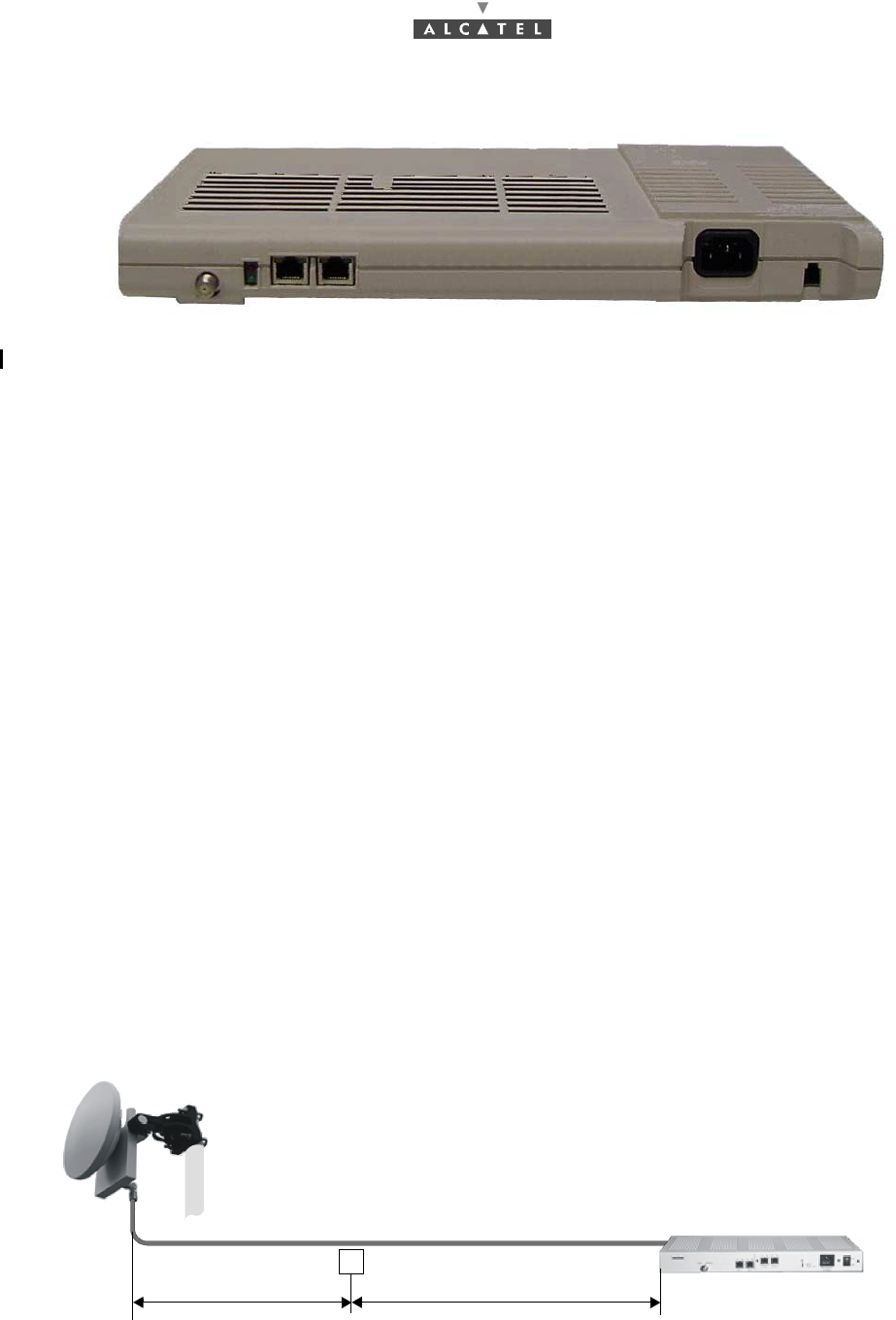
Figure 31 – Earthing the (NCAxxx) NT Lite unit
3.8 Installation of one or more repeater modules
Considerations
–In the case of a coaxial cable to cover a distance greater than 70 meters between the 7390 RT
and the 7390 NT, a repeater module is required to compensate losses.
–Repeaters are installed indoors only, sheltered from dust and heat.
–The repeater must be installed in series on the RT/NT connection (coaxial cable).
–Respect the installation orientation of the repeaters, paying attention to the reference marks on
the casing.
–The repeater needs no setting. It has no individual power supply: the repeater automatically takes
its power from the supply passing through the RT/NT connection.
–The repeater is a fixed gain bi-directional amplifier. This means that the installation instructions
and methodology described below MUST be respected.
Repeater installation instructions
–Between repeater and RT unit, the length of the connection (coaxial cable) is variable: from 0 to
70 meters.
–Between repeater and NT unit, the length of the connection (coaxial cable) is always fixed: 70 me-
ters.
–Between two repeaters, the length of the connection (coaxial cable) is always fixed: 70 meters.
–The system supports a maximum of 2 repeaters per route. Route means the path between an
NT unit and the RT unit.
First example: length of coaxial cable less than 140 m (here, 110 m).
A single repeater is used.
Figure 32 – Installation with one repeater
RT
NT
Example: 40 meters Fixed: 70 meters
Repeater
3CC12423AAAA TQ BJA 01 Issue 01 - March 2001 - Draft 03 47/ 114
52
The variable length (≤ 70 m), is always situated between repeater and RT unit.
The fixed length, 70 m, is always situated between repeater and NT unit.
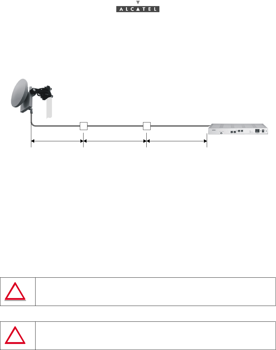
Second example: length of coaxial cable less than 210 m but greater than 140 m (here, 200 m).
Two repeaters are used.
Figure 33 – Installation with two repeaters
Methodology
1. Select the installation location with respect to the location of the NT unit.
2. Install and secure the repeater.
3. Wire the repeater to the NT unit and to the RT unit, respecting the instructions contained in the
installation principles above.
4. Note the real length of the cables installed. The length of each should be ≤ 70 m. This information
will be entered in the database when the equipment is commissioned, using the configuration
software.
Note: The accuracy required by the configuration software is ± 1.5 m.
5. If the last 70 meter section must be coiled, respect a minimum bending radius of 200 mm.
IN ALL CASES, CUMULATED CABLE LENGTH MUST NOT EXCEED 210 METERS
Remind: TWO REPEATERS MAXIMUM PER ROUTE CAN BE SUPPORTED
RT
NT
Example: Fixed:
repeater
Fixed:
repeater
60 meters 70 meters 70 meters
48/ 114 Issue 01 - March 2001 - Draft 03 3CC12423AAAA TQ BJA 01
52
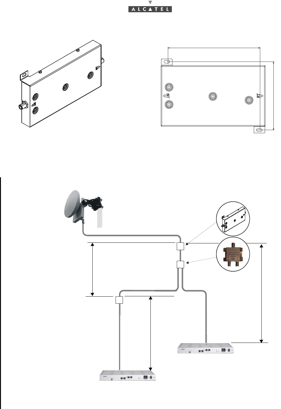
3.9 Installation of one or several repeaters with splitter(s)
Considerations
–Where there are several NT units for a single RT unit, one or several splitter(s) need(s) to be used.
–For a single RT unit it is possible to mount up to 8 NT units.
–The splitter is installed in series on the RT/NT connection (coaxial cable).
–The splitter has no individual power supply: it feeds the power through from the NT to the RT.
–Respect the installation orientation of the repeaters and splitters, paying attention to the reference
marks on the casing.
–The length of the cable used must be noted. In order to facilitate this measurement, refer to the
markings printed every meter, on the outer sheath of the cables. To know the length of cable ins-
talled, subtract the number at one end from the number at the other end of the cable used.
3.9.1 Installation directions for an assembly with 2 NT units
–The system supports a maximum of 2 repeaters and 1 passive splitter per route. Route means
the path between an NT unit and the RT unit.
–The variable distance between an RT and a repeater is from 0 to 70 meters.
–The fixed distance between two repeaters is 70 meters.
–The fixed distance between a repeater and an NT is 70 meters.
–The fixed distance between two repeaters encompassing a passive splitter is 50 meters.
–The fixed distance between a repeater and an NT, and encompassing a splitter, is 50 meters.
–If a fixed length section must be coiled, respect a minimum bending radius of 200 mm.
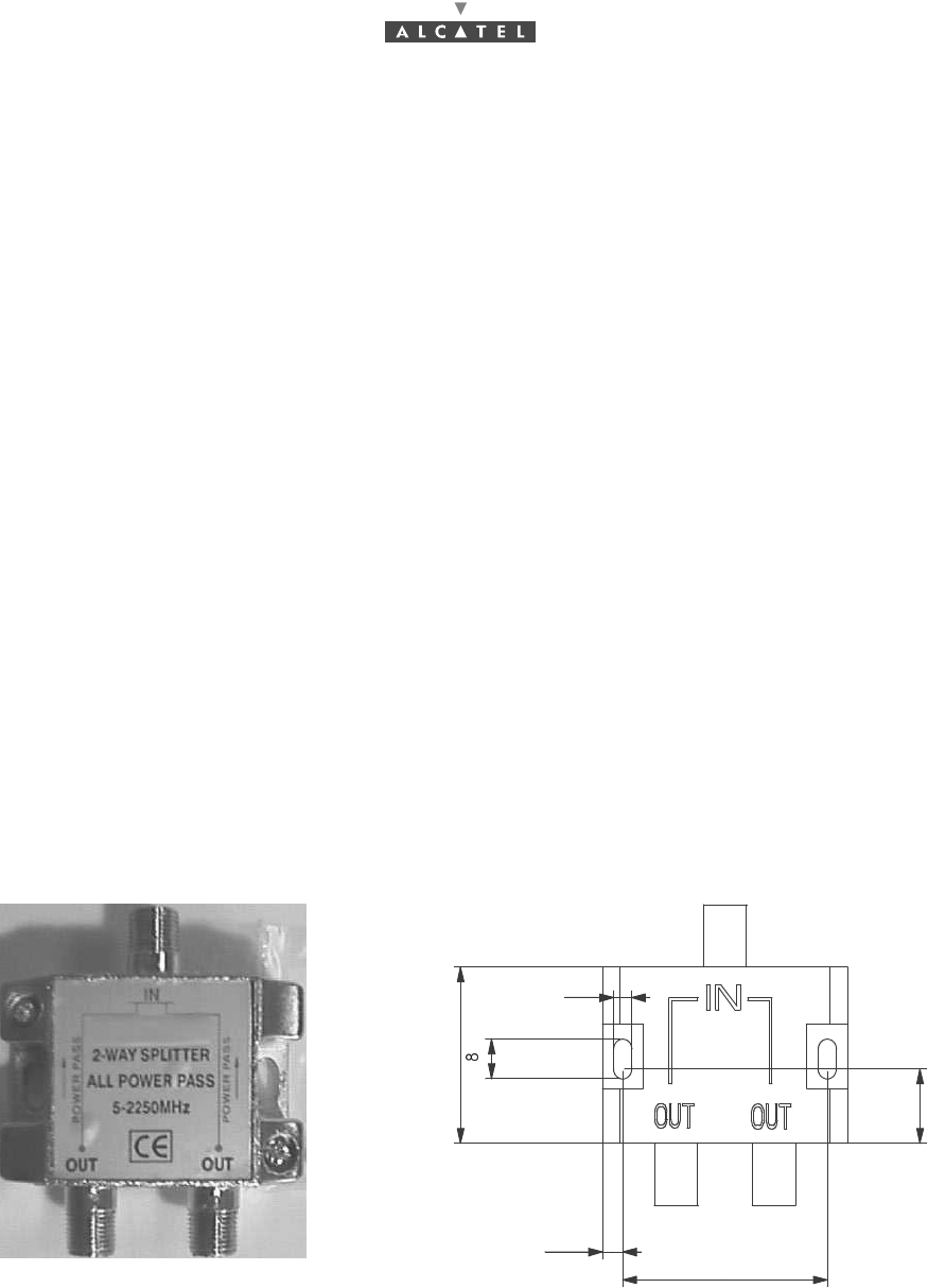
Figure 34 – Passive splitter
15
45
4,5
4
35,5
3CC12423AAAA TQ BJA 01 Issue 01 - March 2001 - Draft 03 49/ 114
52
Figure 35 – Repeater
Example of assembly
This example is well suited to the distribution of NTs on the same floor of a building.
Figure 36 – 2 NT unit assembly
124
RT 15 to 70 meters
NT1
NT2
70 meters
50 meters
repeater
splitter
repeater
50 meters
50/ 114 Issue 01 - March 2001 - Draft 03 3CC12423AAAA TQ BJA 01
52
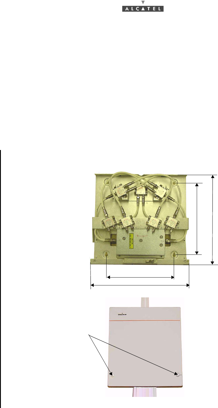
3.9.2 Installation directions for an assembly with 4 NT or 8 NT units (*)
–The active splitter comprises 2 repeaters and 7 passive splitters, see Figure 37 – 8 NT assembly
with active splitter* and Figure 38 – "4 NT" assembly with active splitter.
–This set of components is located in a casing (if necessary, the active splitter may be assembled
on-site via field cabling by the installer).
–The cables between the passive splitter and the other components must then be less than 30 cm.
long.
–The variable distance between a RT and an active splitter is from 20 to 50 m for a standard cable
or from 70 to 140 m for a low-loss cable.
–The fixed distance between an active splitter and an NT is 24 m for a standard cable.
–The fixed distance around a repeater from an active splitter to an NT is 94 m for a standard cable.
–For each access not used by an NT, add a 75 Ohm load.
Example of assembly with active splitter:
Note: The active splitter unit is locked by two special bolts. Use the tool splitter 8V Torx T15 to unlock
it.
Figure 37 – 8 NT assembly with active splitter*
Special bolts
Inside view
Outside view
The dimensions are in millimeters
300
280
Use the included fixing kit
362
386
Height : 96 mm