Alcatel Canada 28T36A06A11A Mainstreet Broadband Wireless System - BTS Unit User Manual 2bwireless
Alcatel Canada Inc Mainstreet Broadband Wireless System - BTS Unit 2bwireless
UserManual.wiki
>
Alcatel Canada
>
28T36A06A11A User Manual
Draft Instruction Manual
Navigation menu
Upload a User Manual
Namespaces
Wiki Guide
HTML
PDF
Info
Views
User Manual
Discussion / Help
Navigation
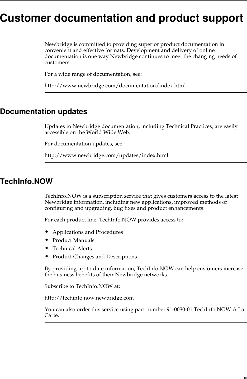
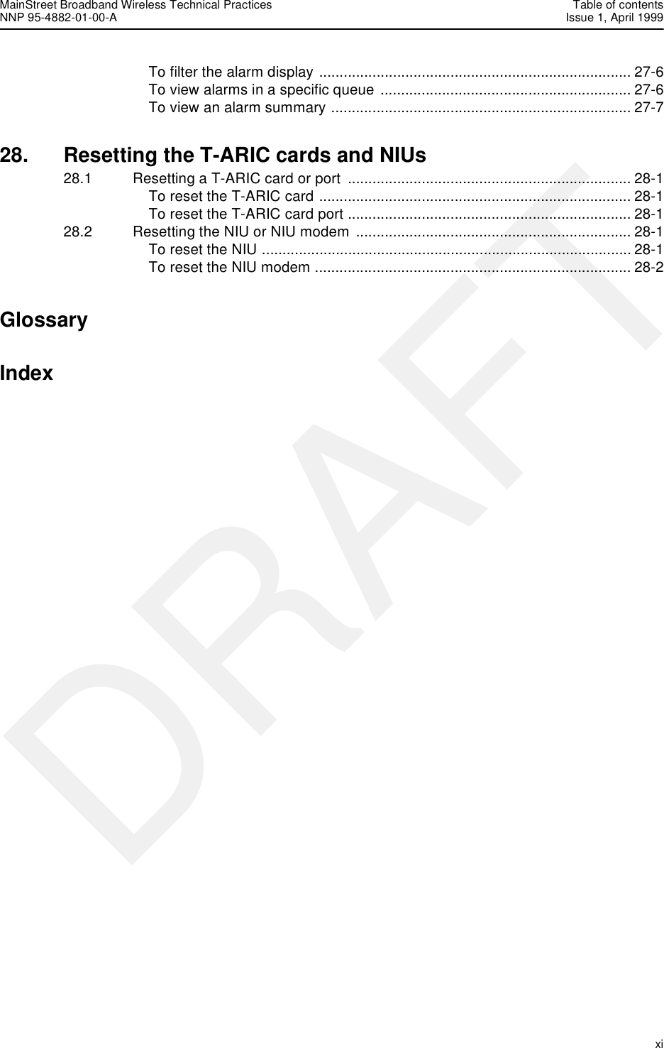
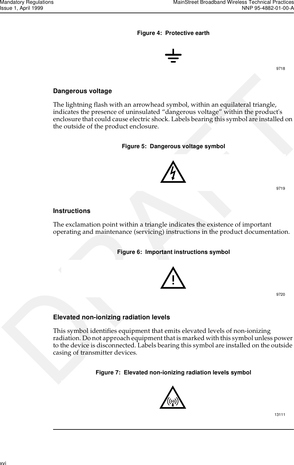
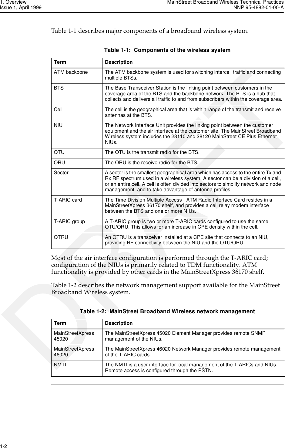
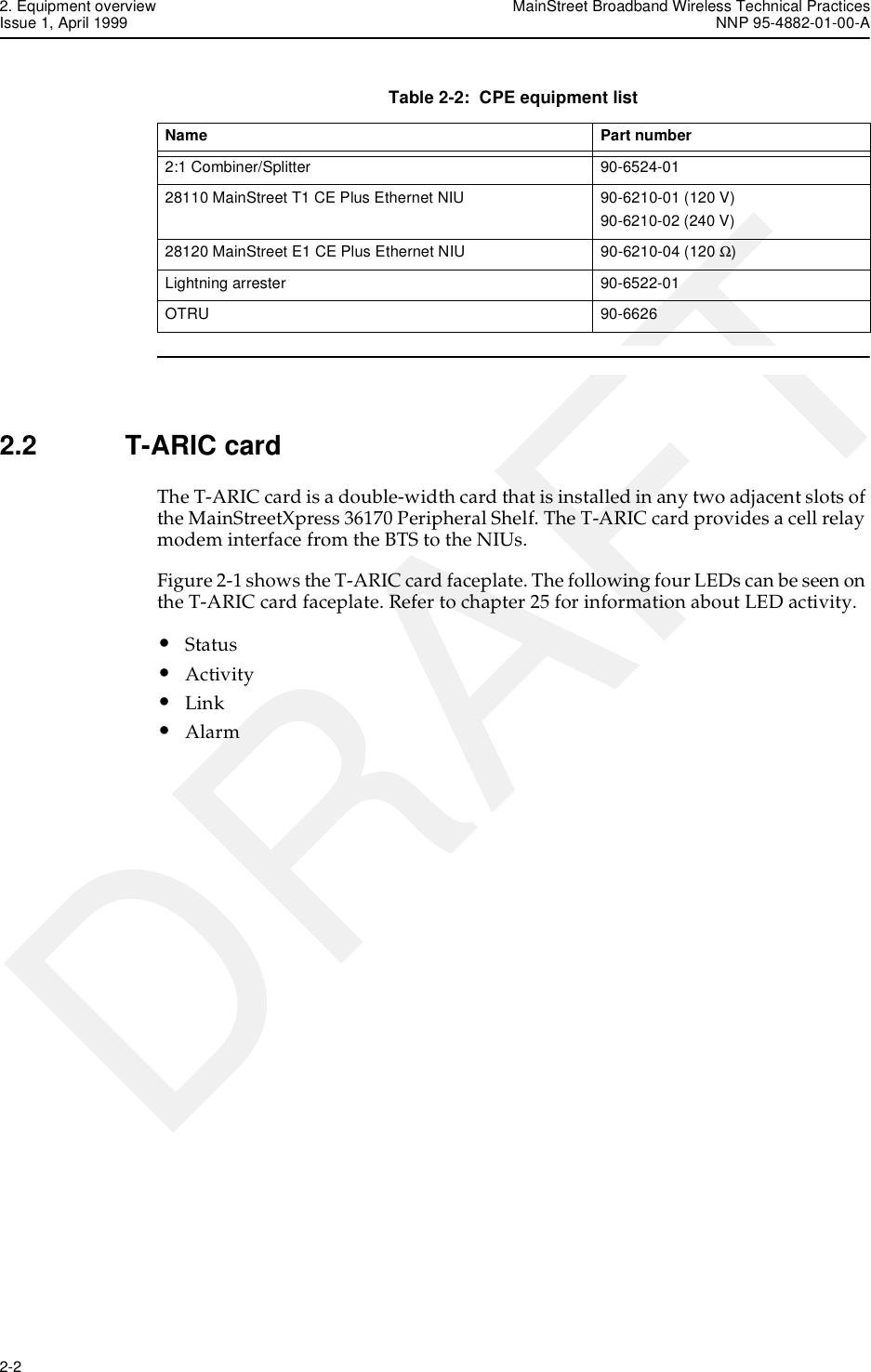
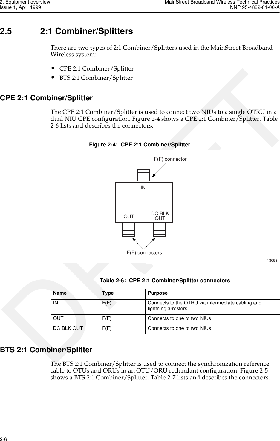
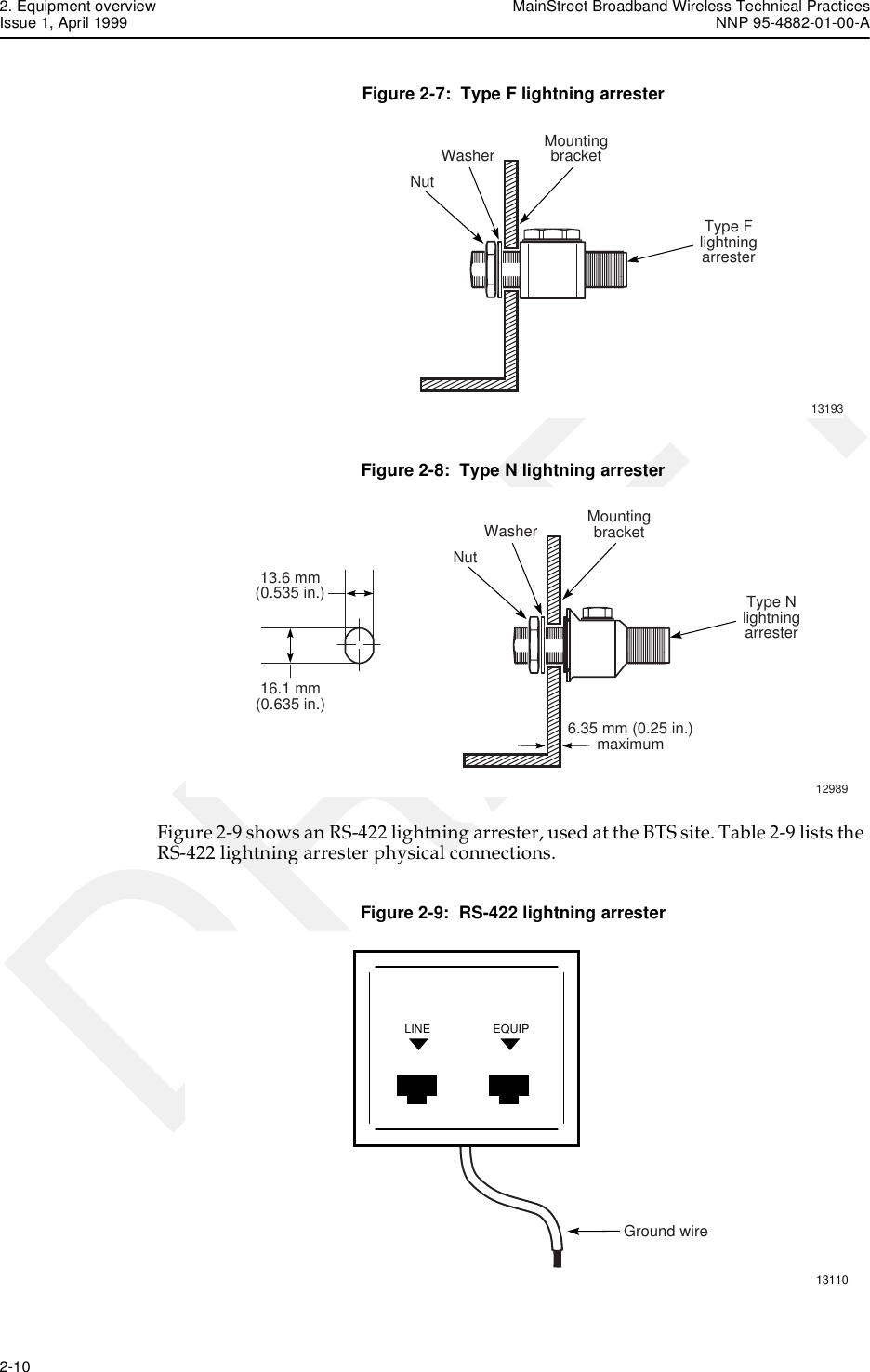
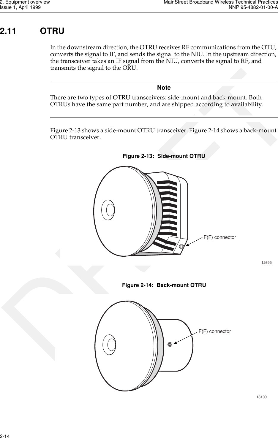
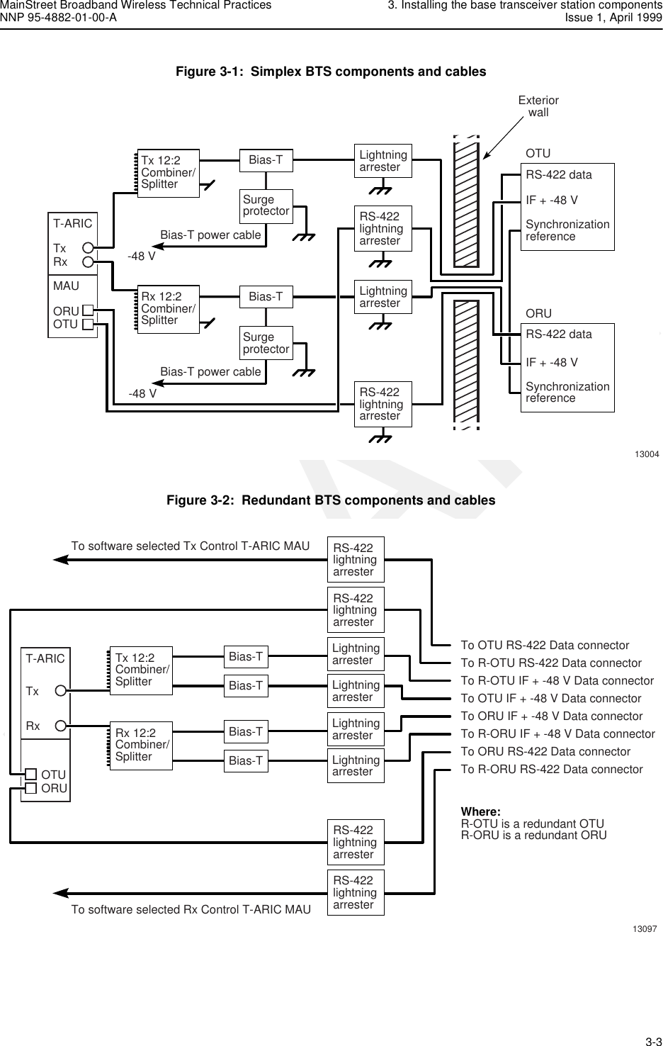
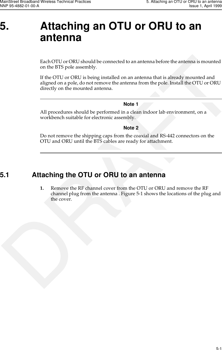
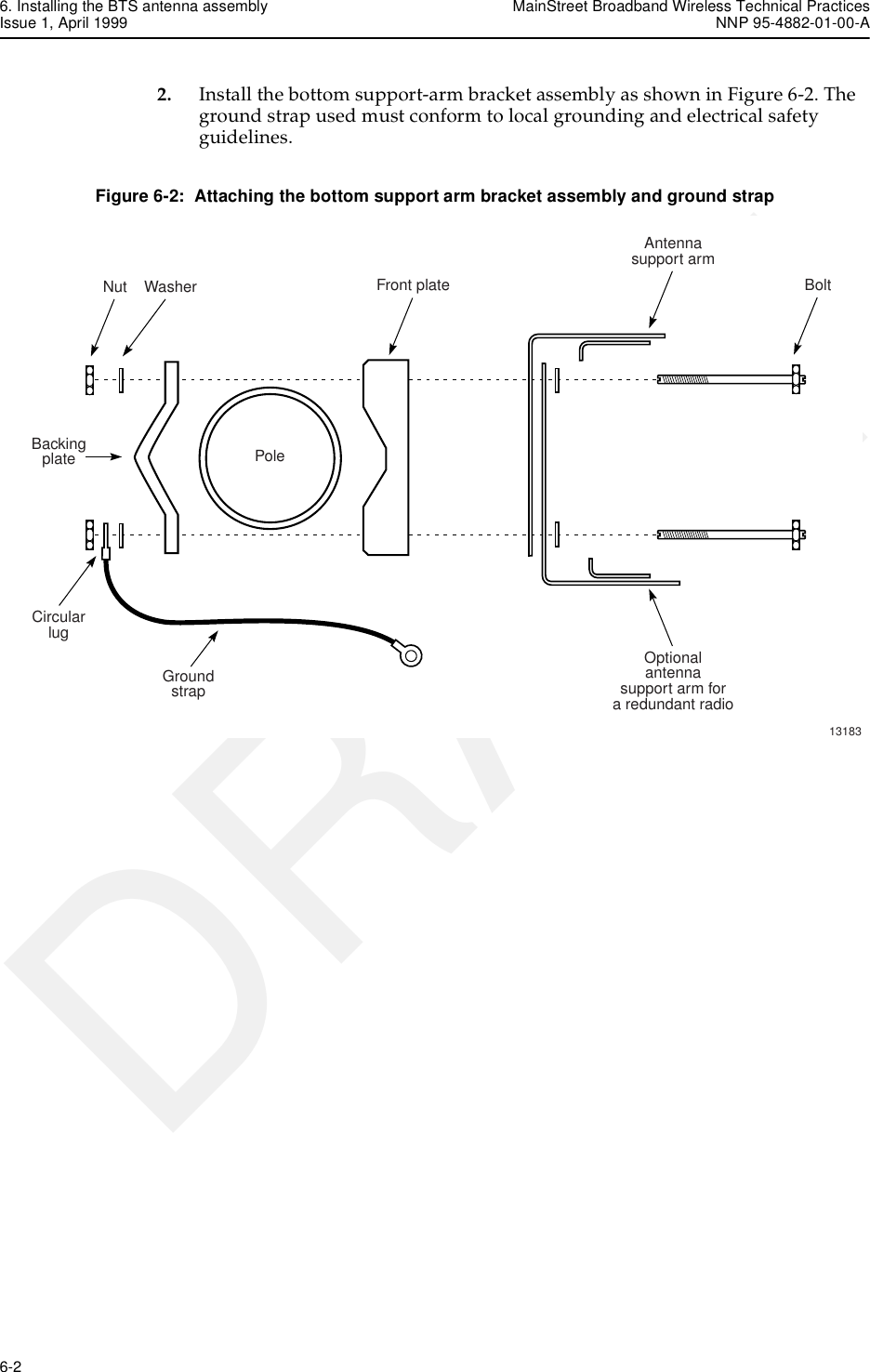
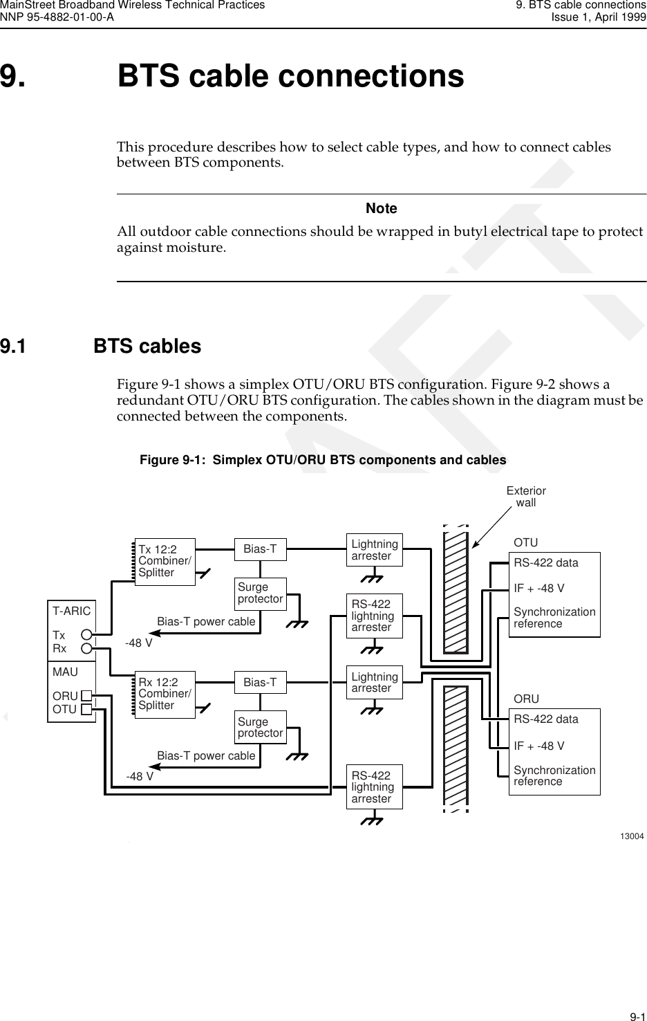
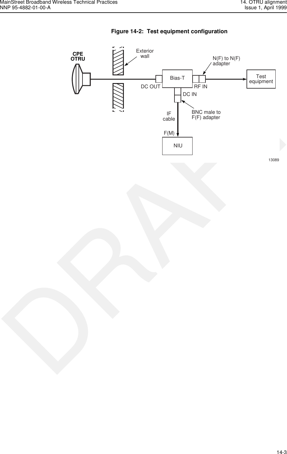
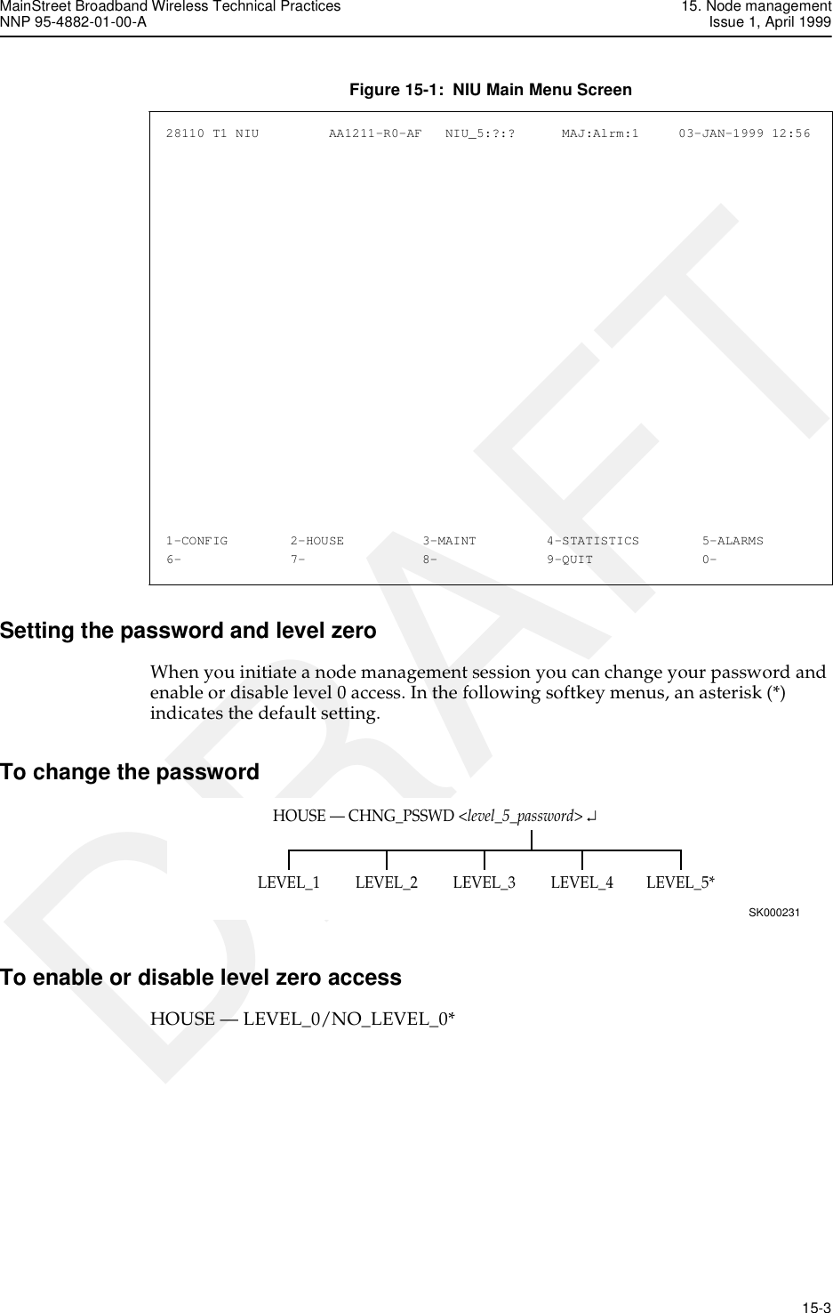
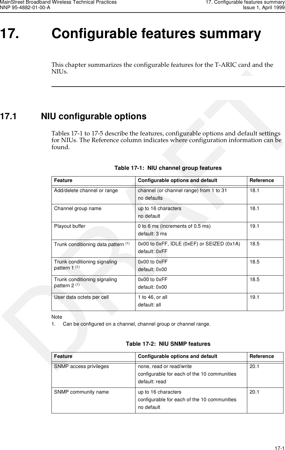
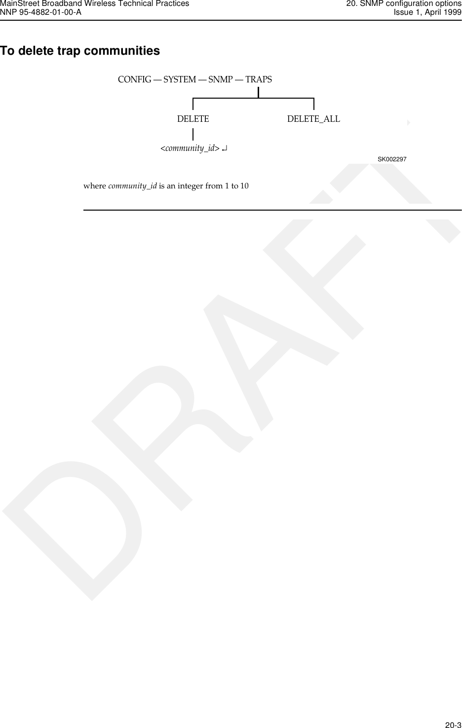
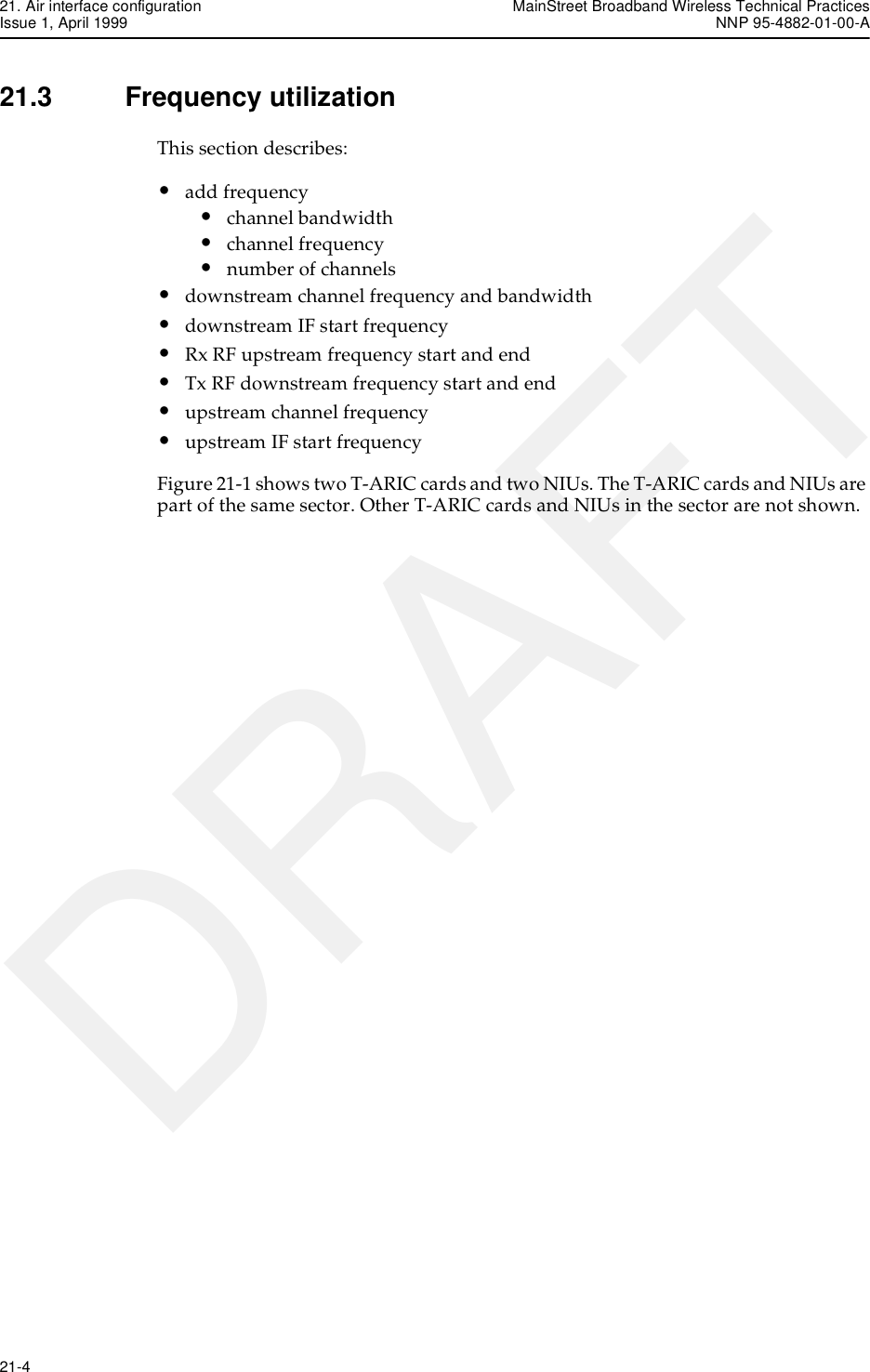
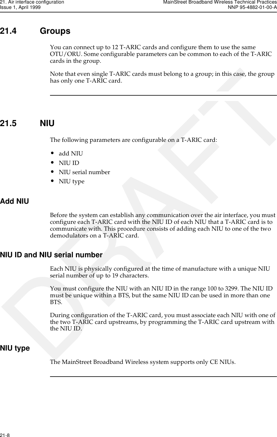
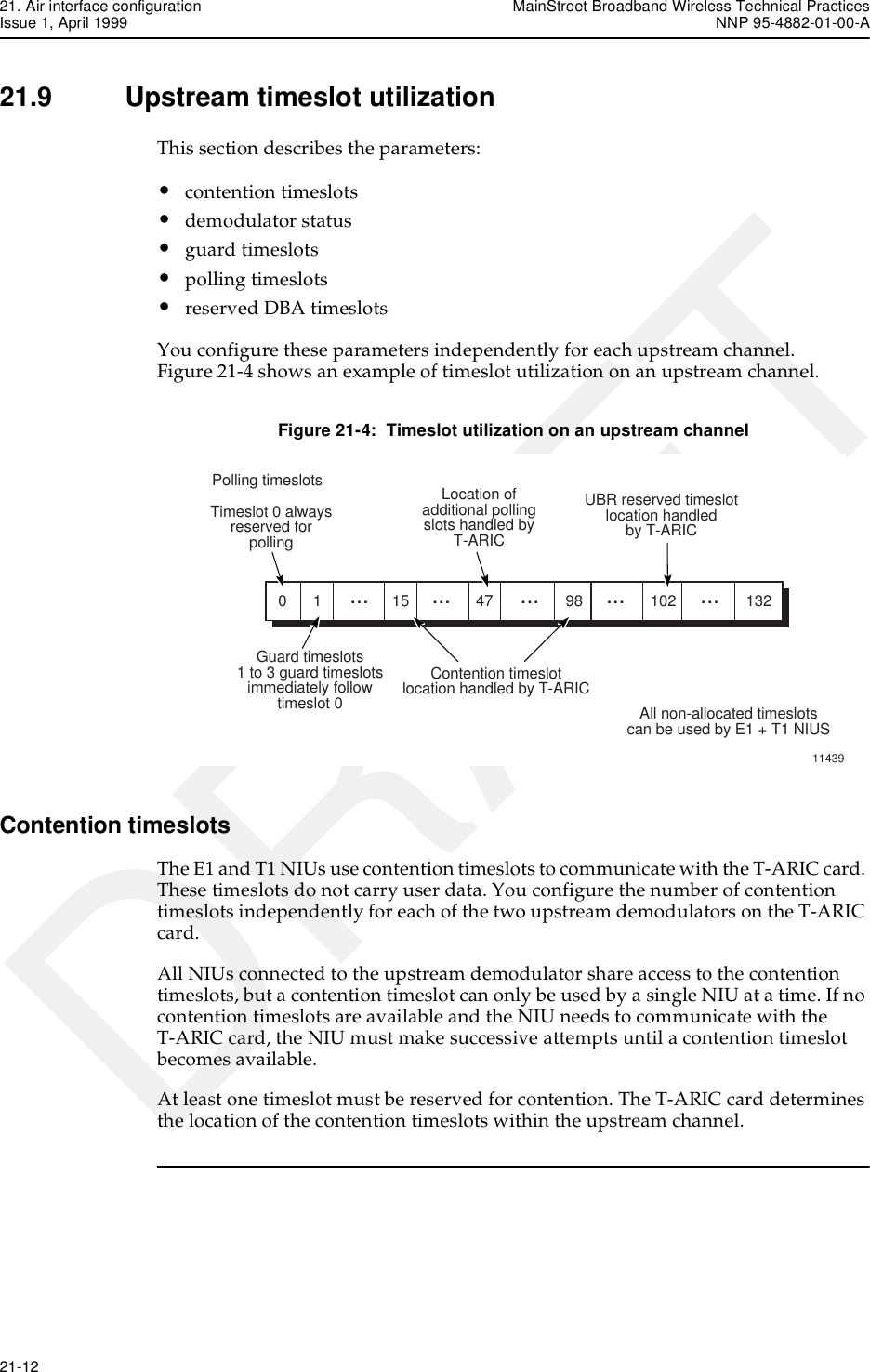
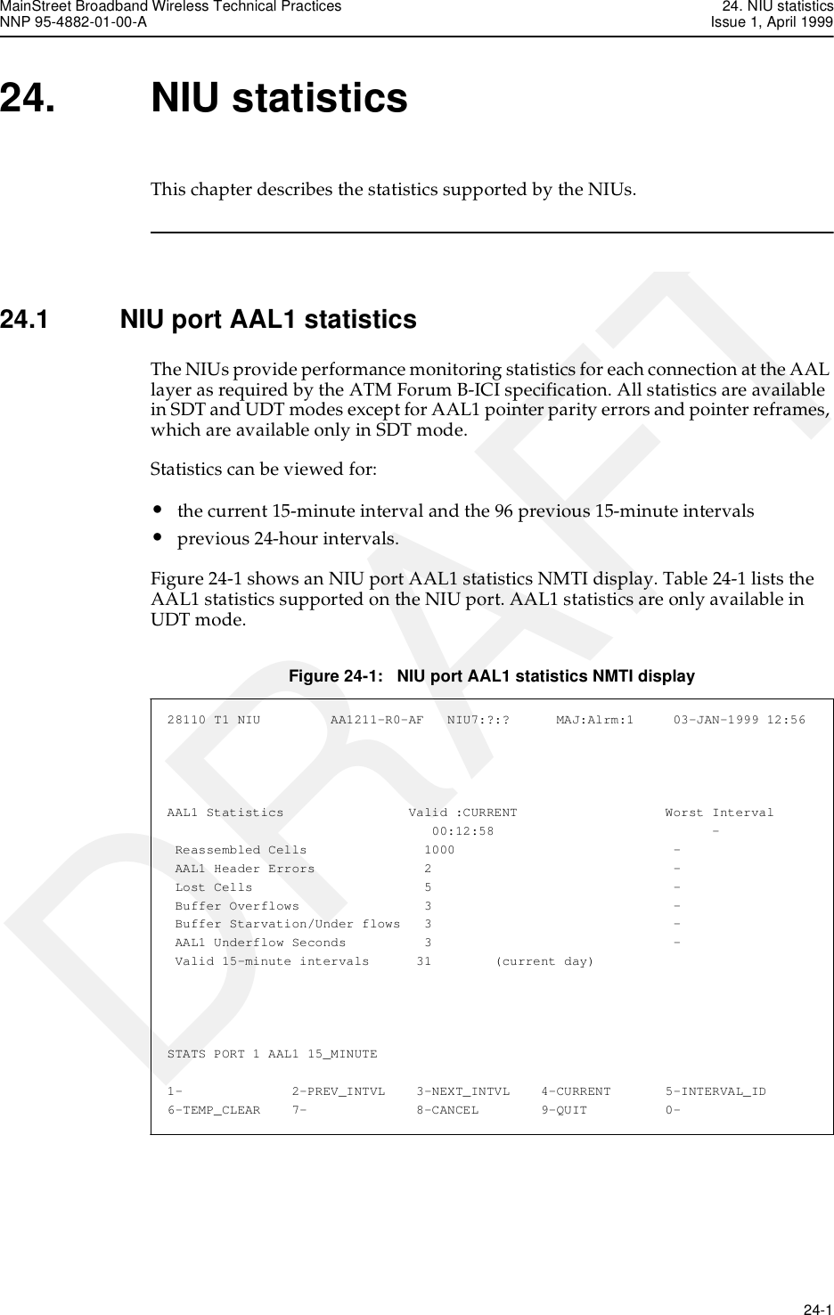
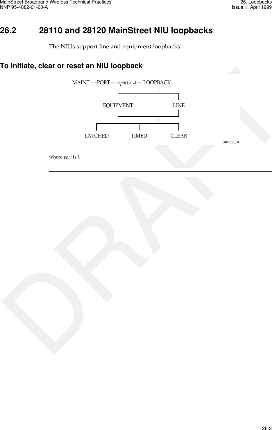
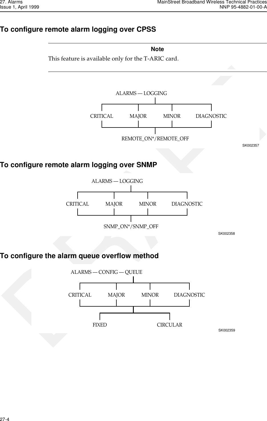
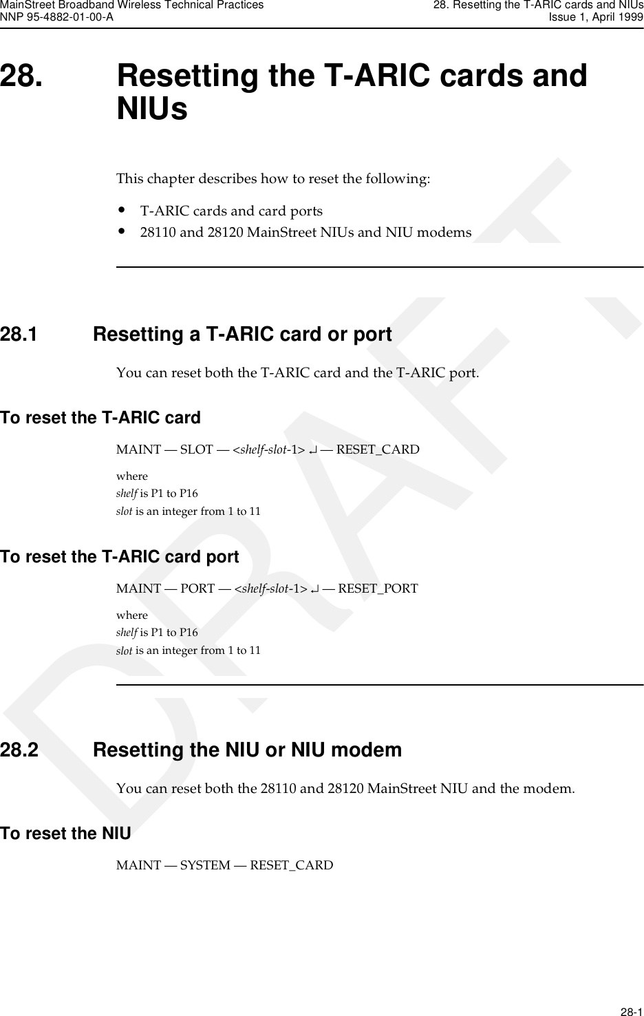
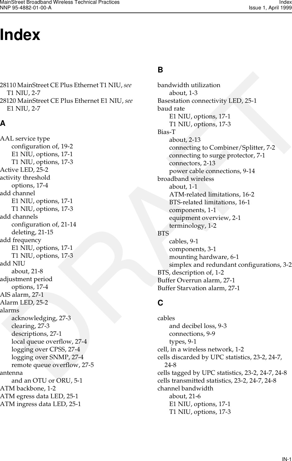
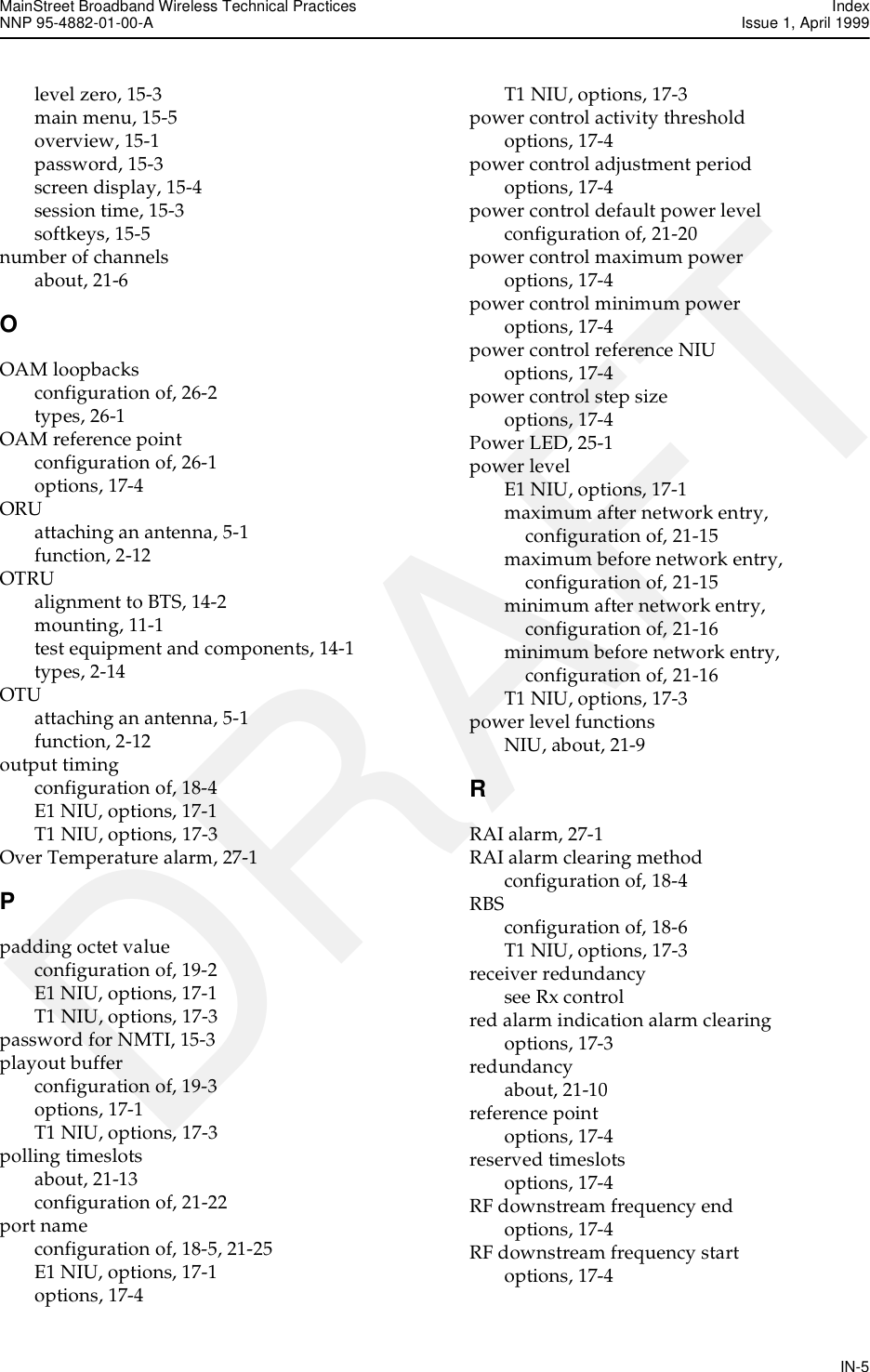
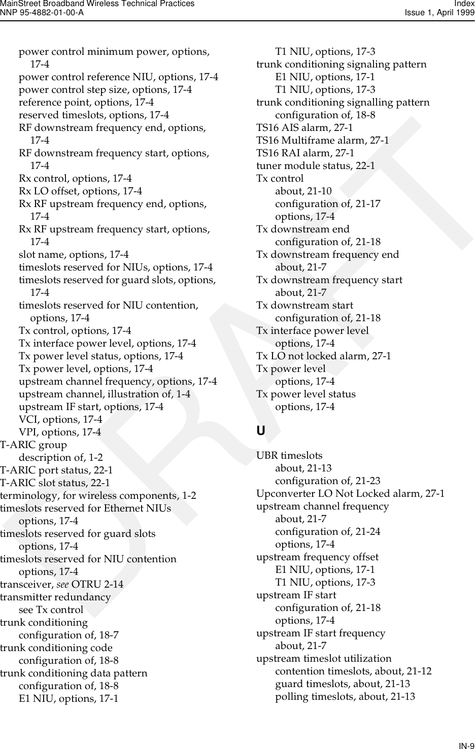
![9. BTS cable connections MainStreet Broadband Wireless Technical PracticesIssue 1, April 1999 NNP 95-4882-01-00-A9-2 DRAFTFigure 9-2: Redundant OTU/ORU BTS components and cablesTable 9-1 lists the cables used to connect the OTU, ORU and the T-ARIC card. Table 9-2 lists the part numbers for the BTS cable connectors.Table 9-1: BTS cablesTxT-ARICRxBias-T To OTU RS-422 Data connectorTo software selected Tx Control T-ARIC MAUTo software selected Rx Control T-ARIC MAUTo R-OTU RS-422 Data connectorTo R-OTU IF + -48 V Data connectorTo OTU IF + -48 V Data connectorTo ORU IF + -48 V Data connectorTo R-ORU IF + -48 V Data connectorTo ORU RS-422 Data connectorTo R-ORU RS-422 Data connectorWhere:R-OTU is a redundant OTUR-ORU is a redundant ORUBias-TLightningarresterLightningarresterBias-TBias-TLightningarresterLightningarresterRx 12:2Combiner/SplitterOTUORUTx 12:2Combiner/Splitter13097RS-422lightningarresterRS-422lightningarresterRS-422lightningarresterRS-422lightningarresterPhysical path Intermediate cables Connectors Recommended cable specificationOTU IF and -48 V to 12:2 Combiner/Splitter OTU to lightning arresterLightning arrester to Bias-TN(M) - N(M)N(M) - N(M)LDF4-50ALDF5-50ALDF6-50ACR 50-540-PECR-50-1070-PECR-50-1873-PEORU IF and -48 V to 12:2 Combiner/Splitter ORU to lightning arresterLightning arrester to Bias-TN(M) - N(M)N(M) - N(M)LDF4-50ALDF5-50ALDF6-50ACR 50-540-PECR-50-1070-PECR-50-1873-PE12:2 Combiner/Splitter to T-ARIC Tx connector n/a N(M) - SMA(M) 90-6656-01 (3 m [10 ft])90-6656-02 (6 m [20 ft])12:2 Combiner/Splitter to T-ARIC Rx connector n/a N(M) - SMA(M) 90-6656-01 (3 m [10 ft])90-6656-02 (6 m [20 ft])](https://usermanual.wiki/Alcatel-Canada/28T36A06A11A/User-Guide-35880-Page-62.png)
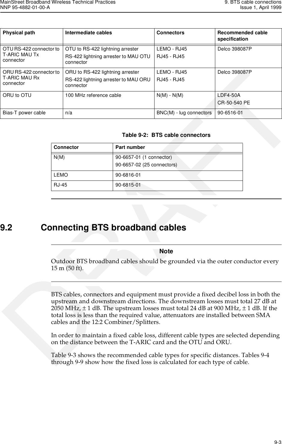
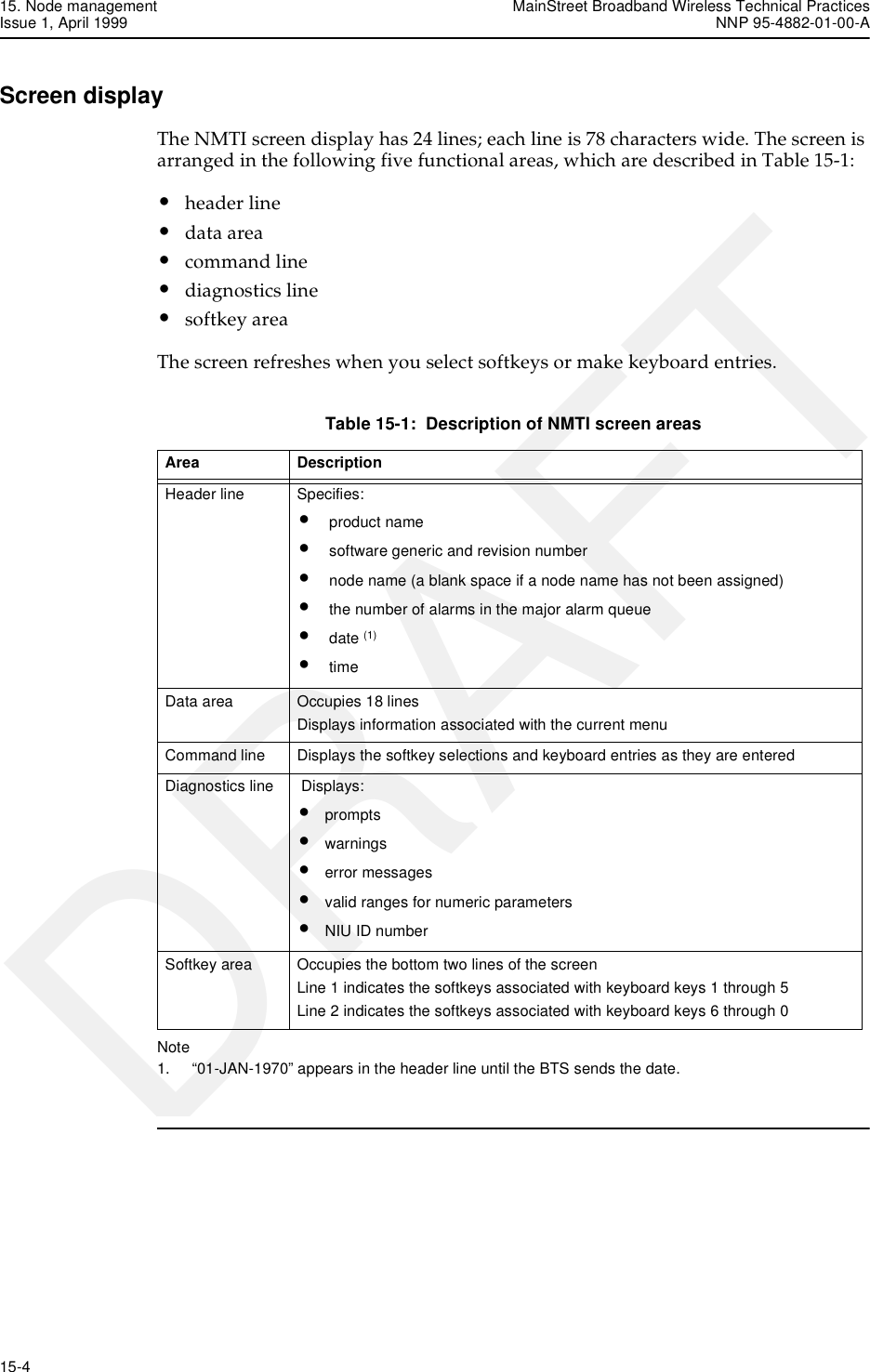
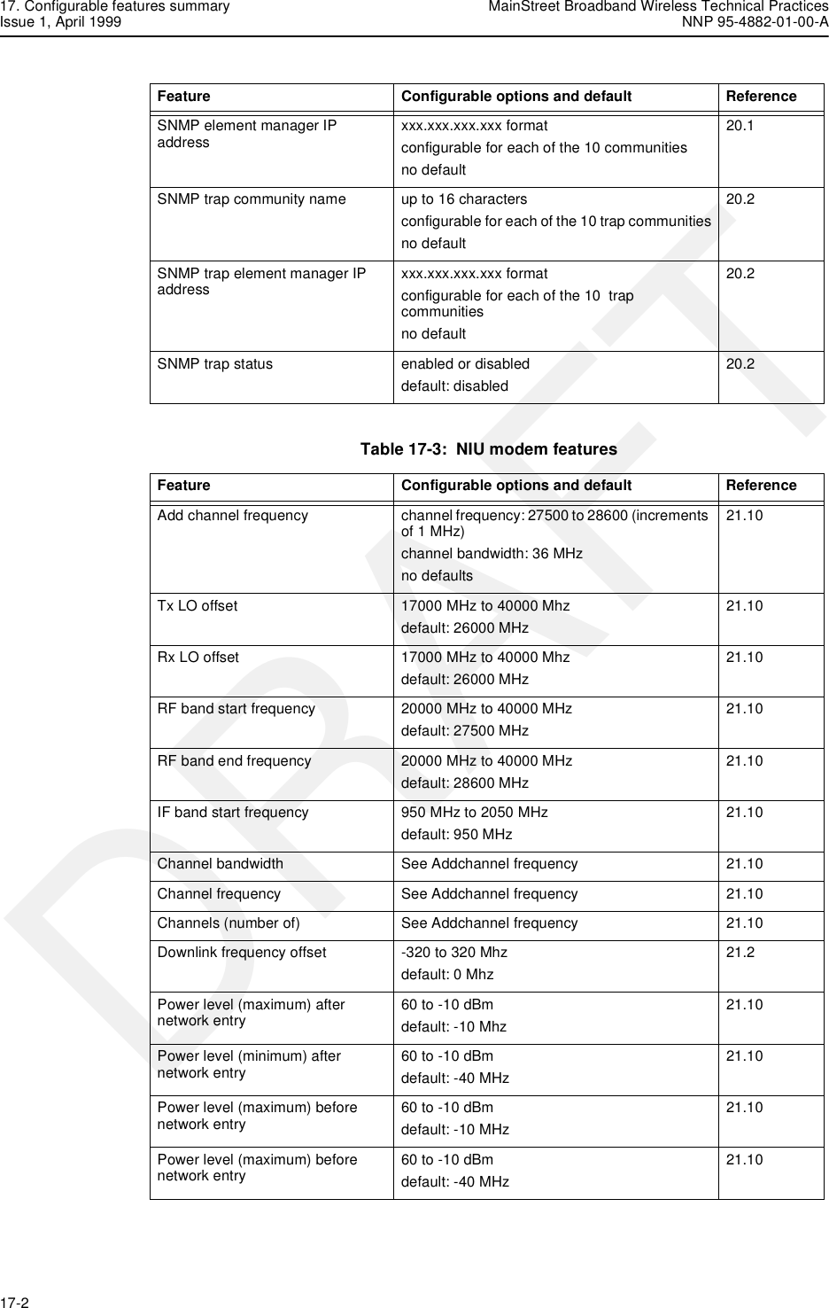
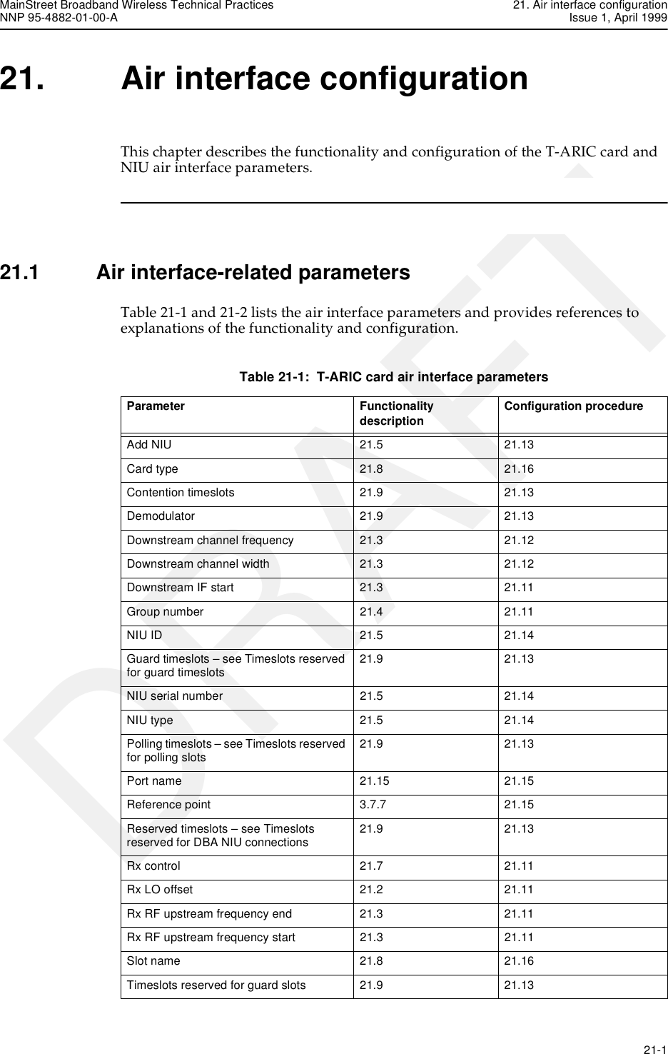
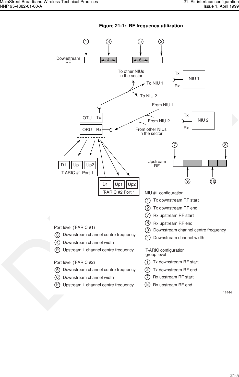
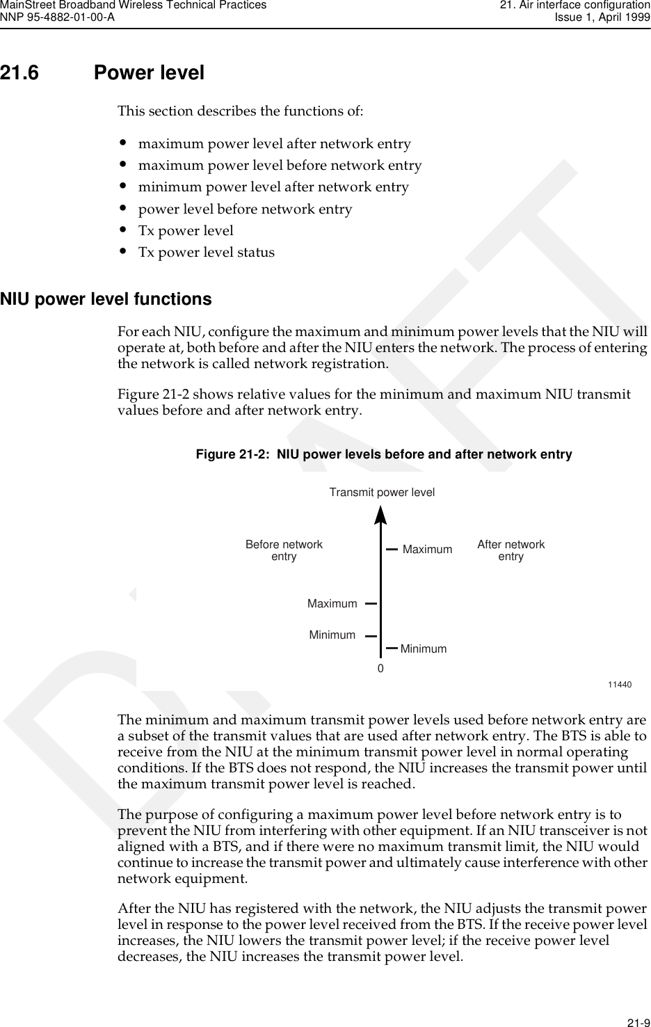
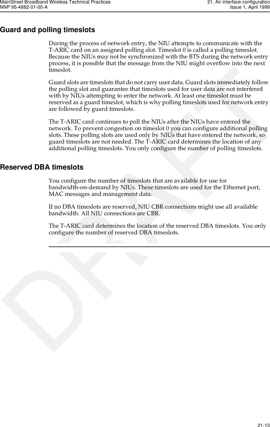
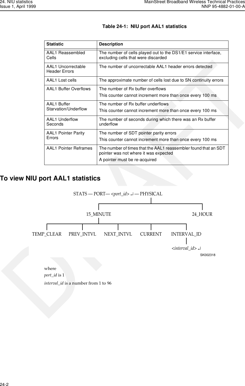
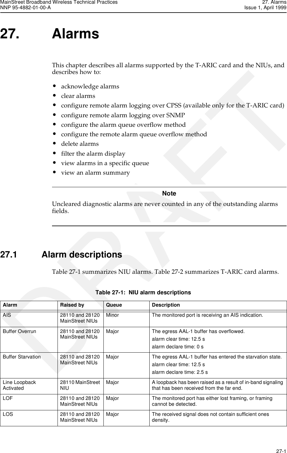
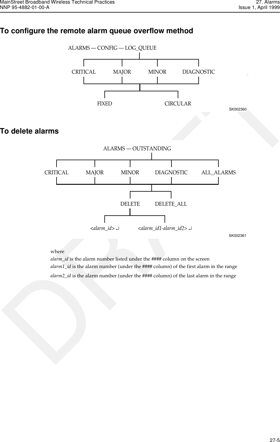
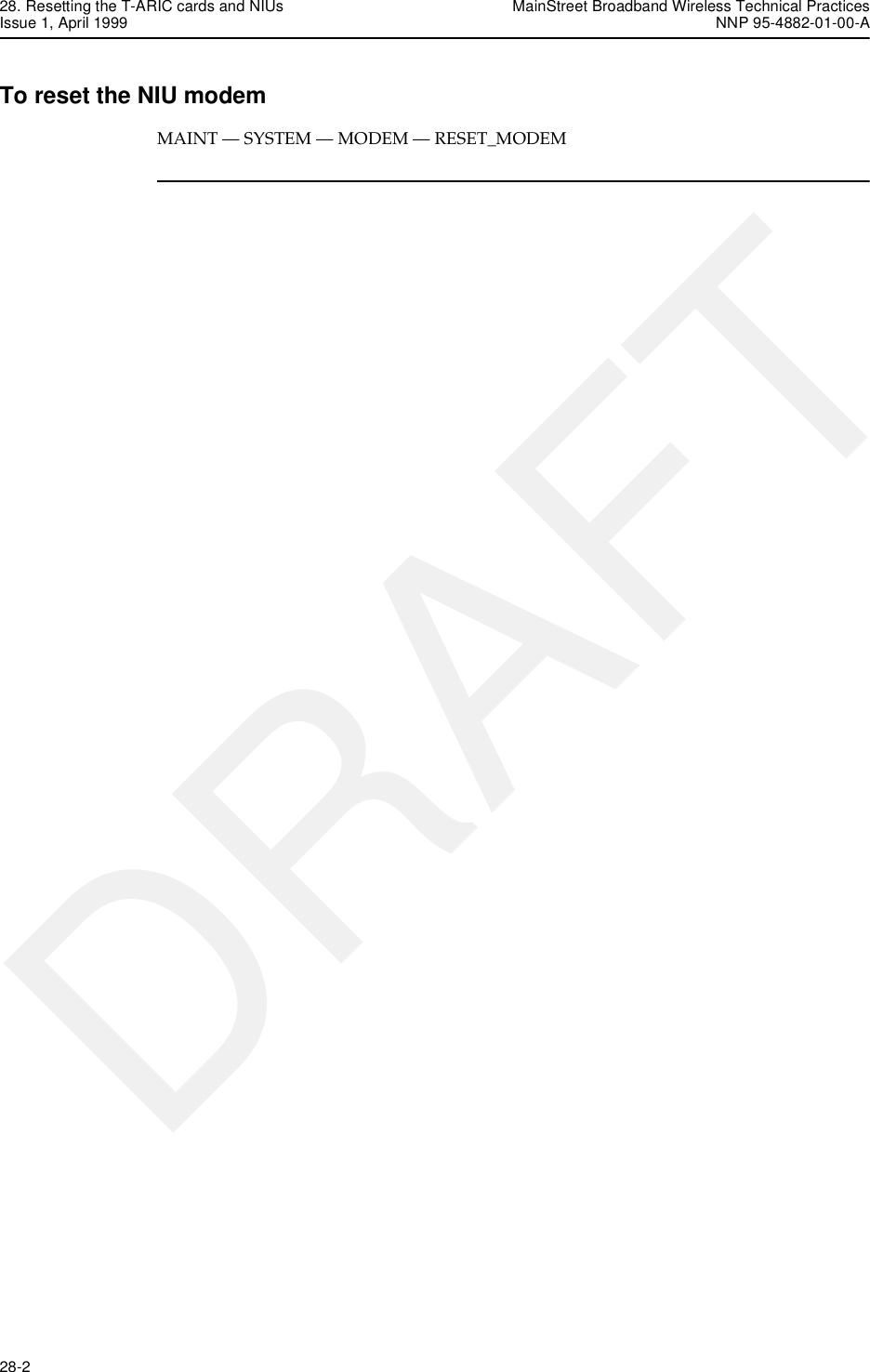
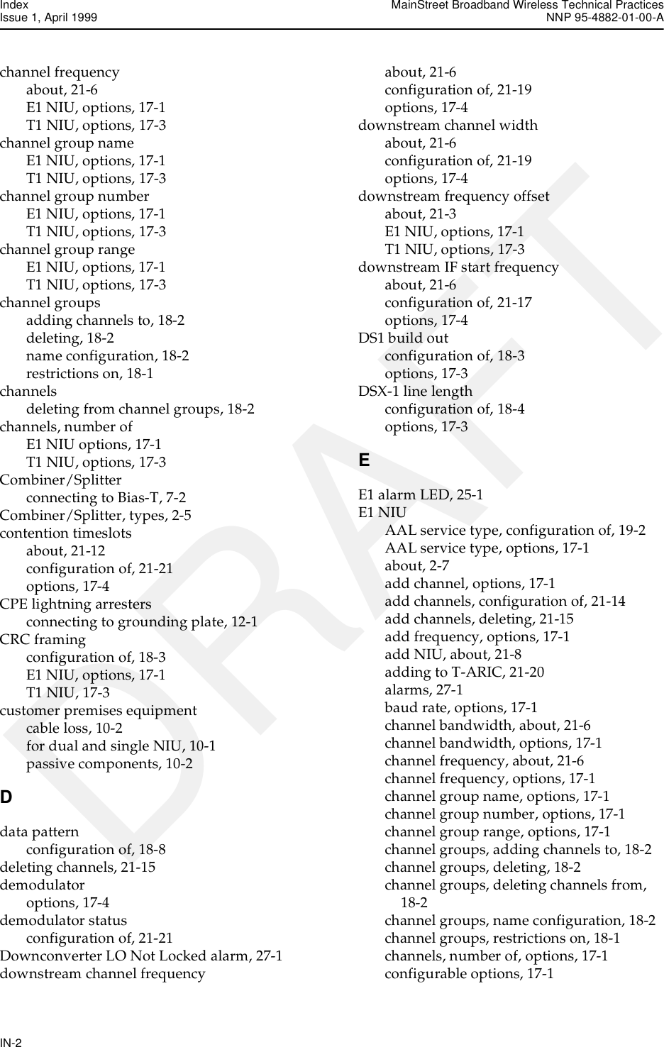
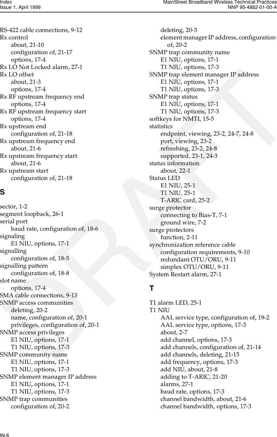
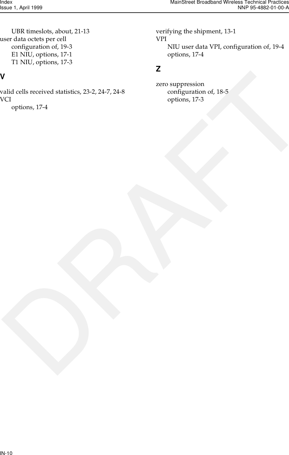
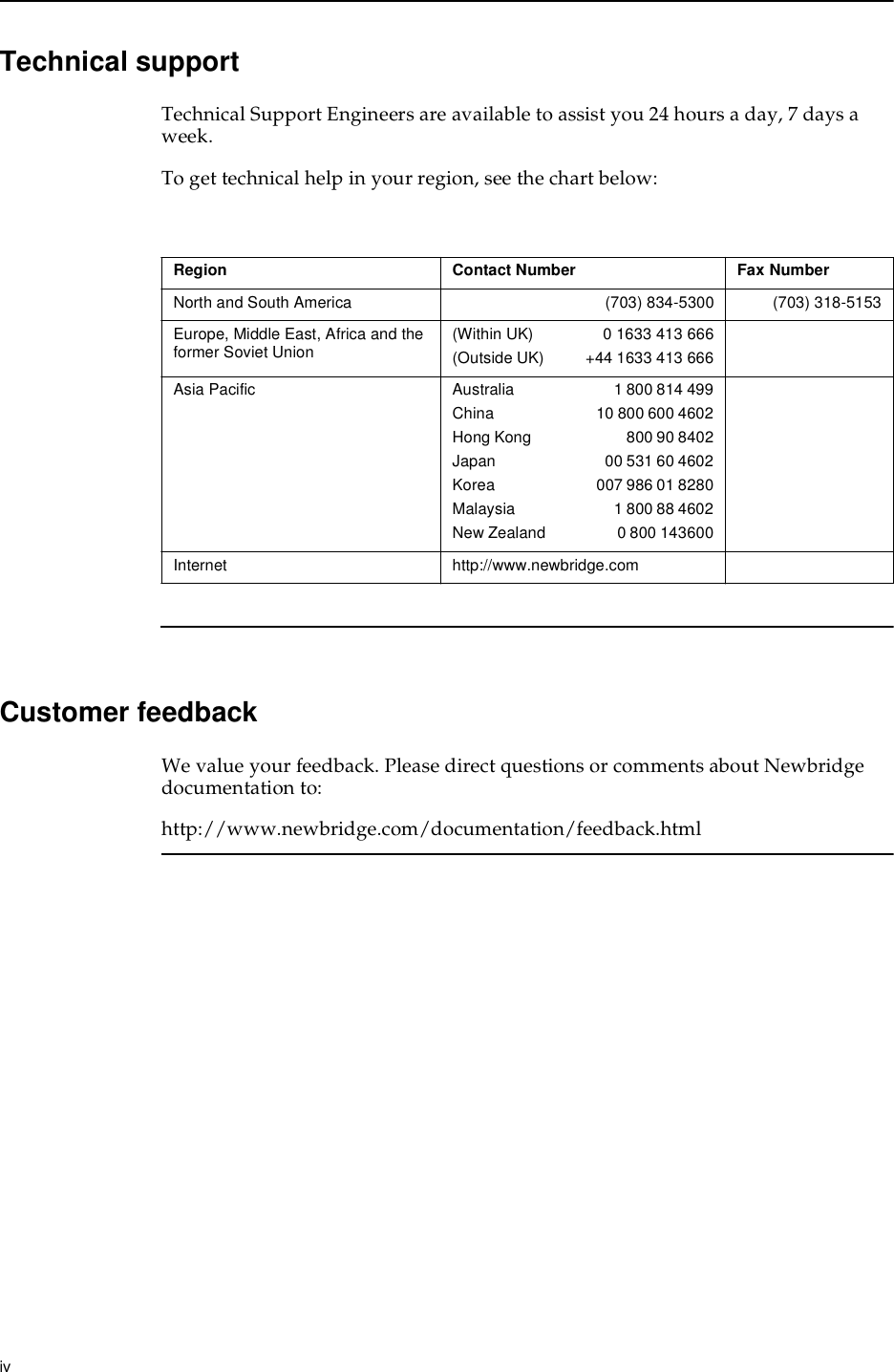
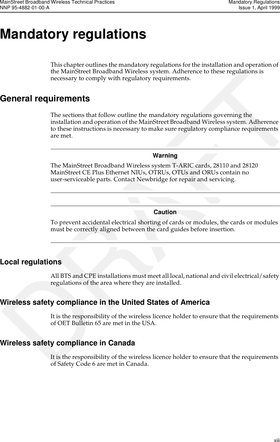
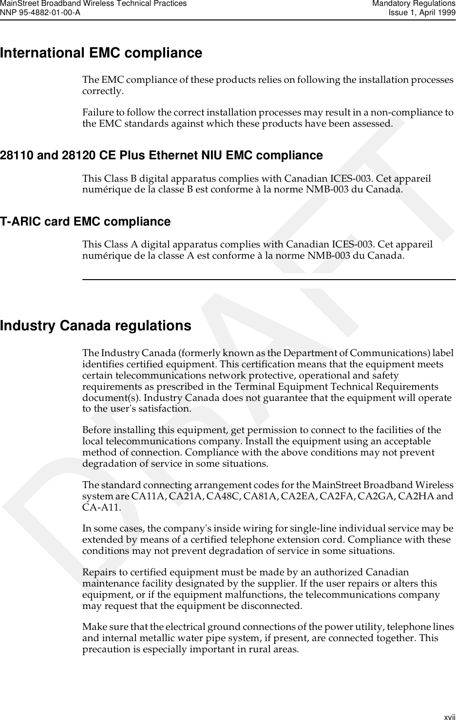
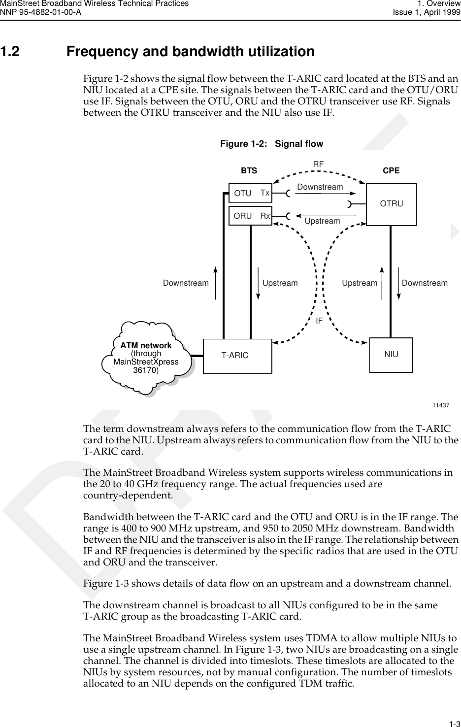
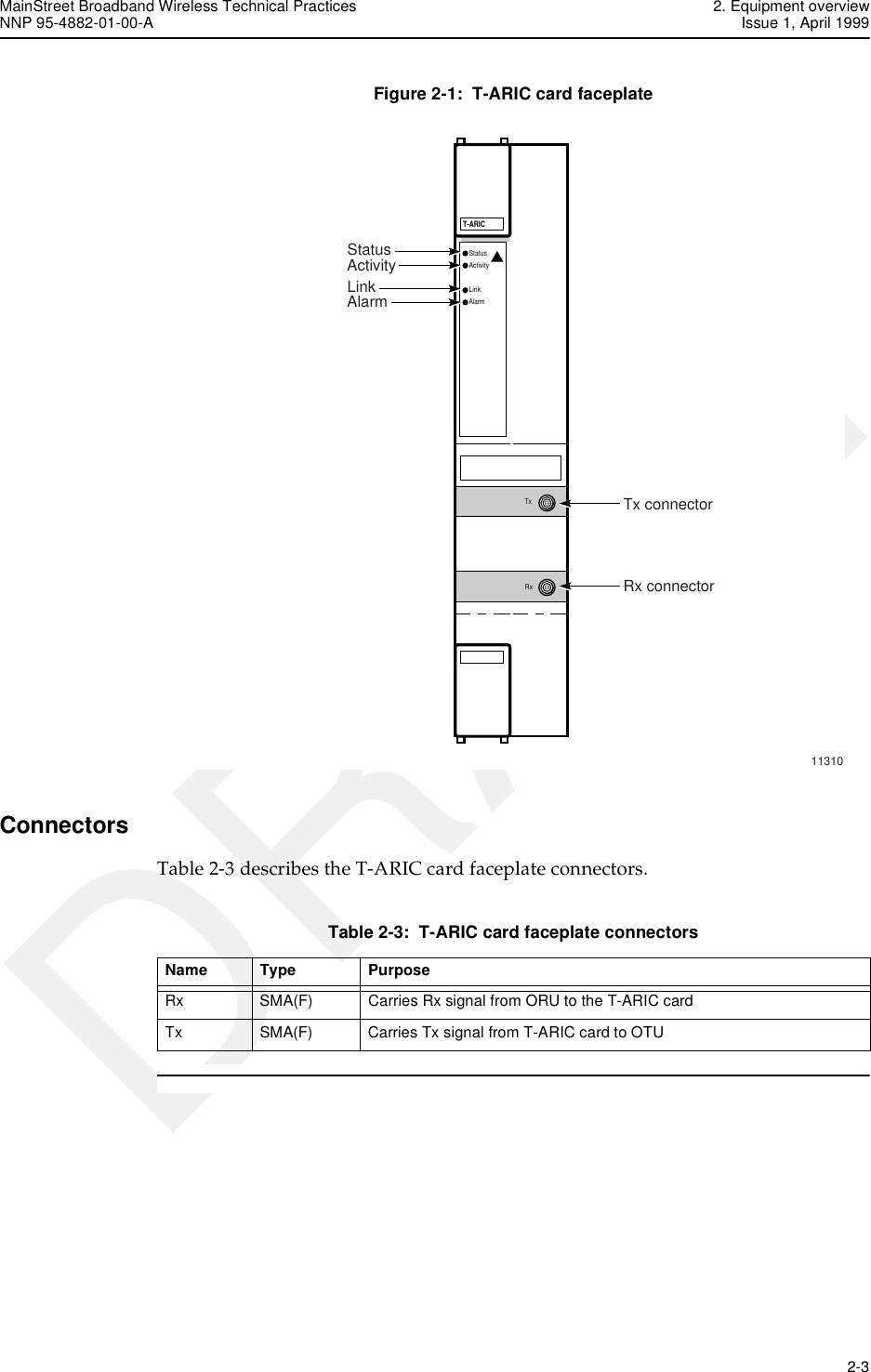
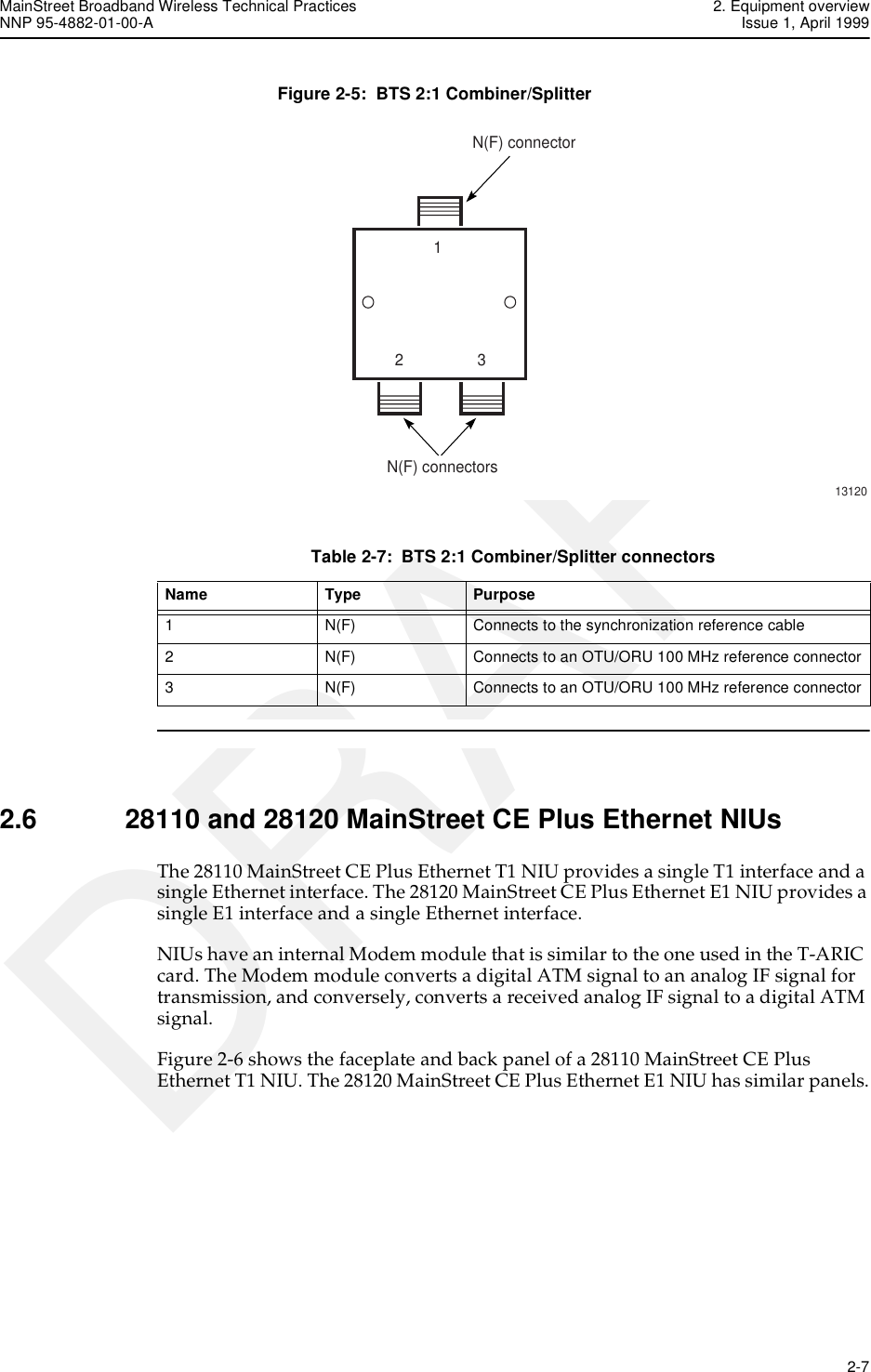
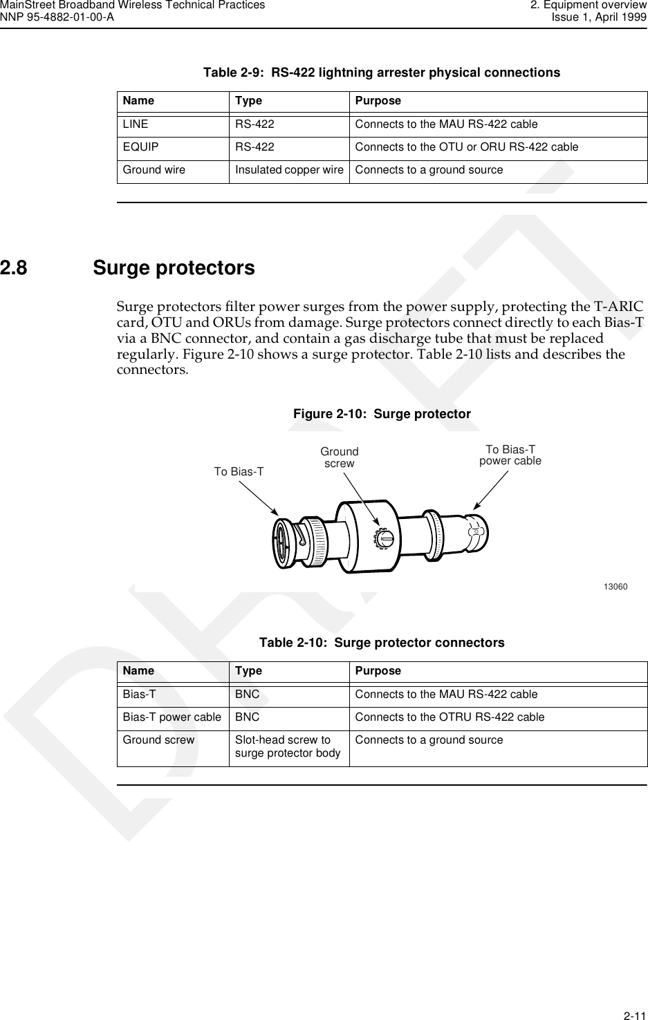
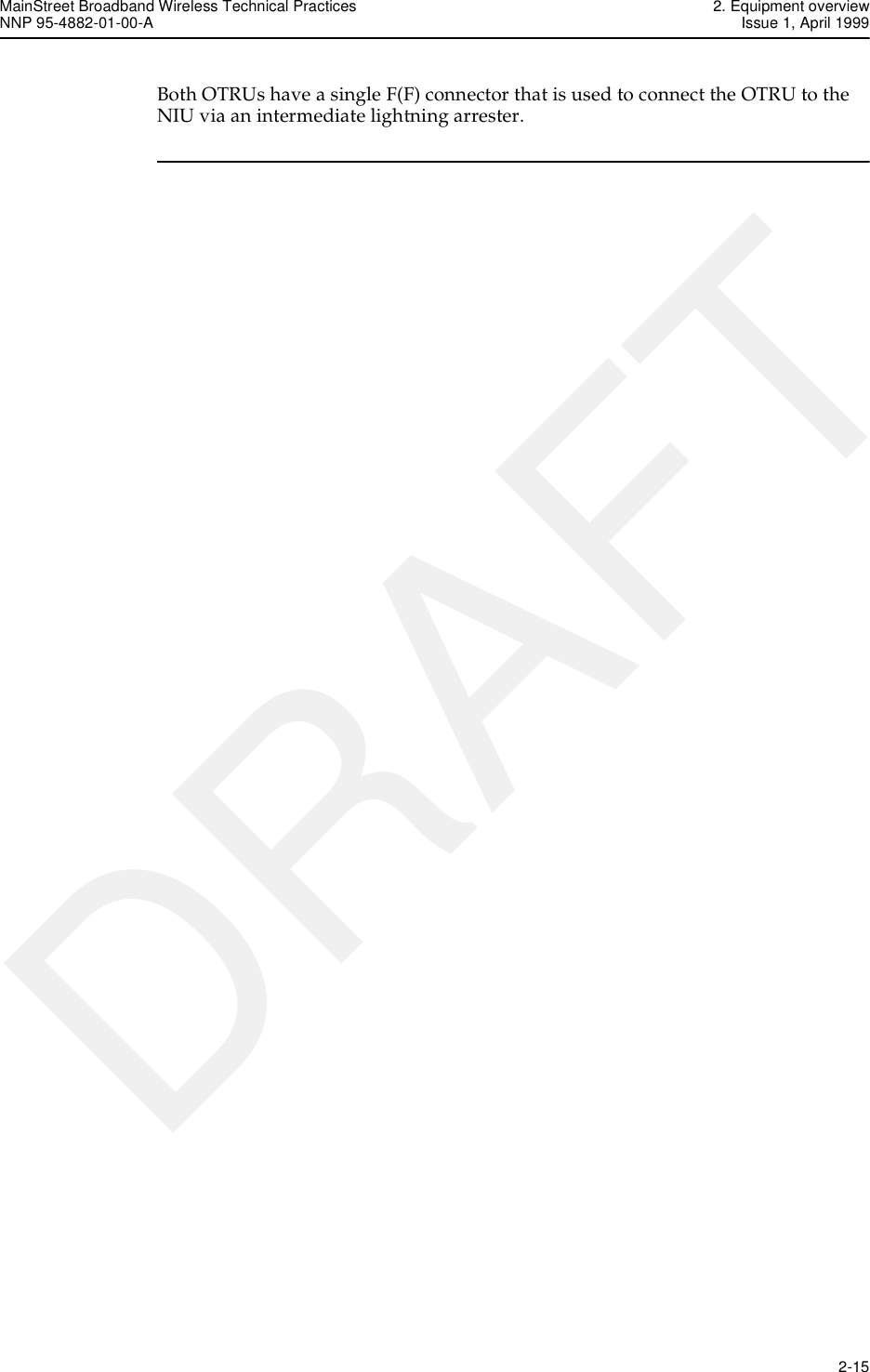
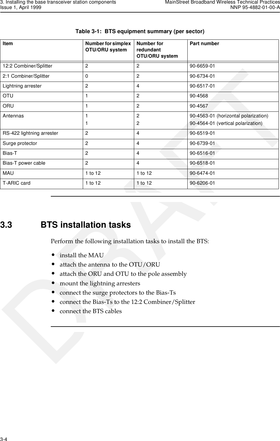
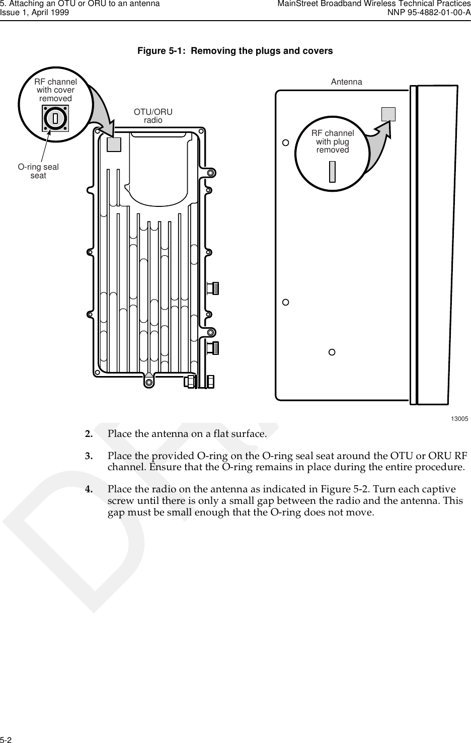
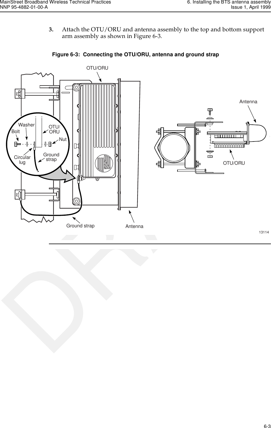
![9. BTS cable connections MainStreet Broadband Wireless Technical PracticesIssue 1, April 1999 NNP 95-4882-01-00-A9-4 DRAFTTable 9-3: Cable lengths and typesTable 9-4: LDF4-50A cable (60 m [196 ft]) decibel loss calculationsDistance Cable type Supplier Loss calculations60 m (196 ft) LDF4-50A Andrew Table 9-4120 m (394 ft) LDF5-50A Andrew Table 9-5150 m (492 ft) LDF6-50A Andrew Table 9-670 m (230 ft) CR50-540-PE CommScope Table 9-7120 m (394 ft) CR50-1070-PE CommScope Table 9-8200 m (656 ft) CR50-1873-PE CommScope Table 9-9BTS item MaxVSWR (x:1)Downstreamloss(2050 MHz)(dB)Upstreamloss(900 MHz)(dB)Downstreaminsertion andcoupling loss(2050 MHz)(dB)Upstreaminsertion andcoupling loss(900 MHz)(dB)DownstreamVSWR correctedloss (2050 MHz)(dB)UpstreamVSWR correctedloss (900 MHz)(dB)1 × T-ARIC SMA cable (3 m [10 ft]) 1.35 0.467 .333 1.40 1.00 1.46 1.051 × OTU 12.2 Combiner/Splitter 1.30 3.000 0.000 14.00 0.00 17.10 0.001 × ORU 12:2 Combiner/Splitter 1.30 0.000 2.500 0.00 14.00 0.00 16.591 × Bias-T 1.30 1.000 1.000 1.00 1.00 1.03 1.031 × surge protector 1.10 0.200 0.200 0.20 0.20 0.20 0.201 × cable LDF4-50A (60 m [196 ft])1.20 0.065 0.040 7.75 4.80 7.88 4.884 × cable connectors 1.20 0.200 0.200 0.80 0.80 0.94 0.94Total loss — — — 25.15 21.80 28.63 24.69](https://usermanual.wiki/Alcatel-Canada/28T36A06A11A/User-Guide-35880-Page-64.png)
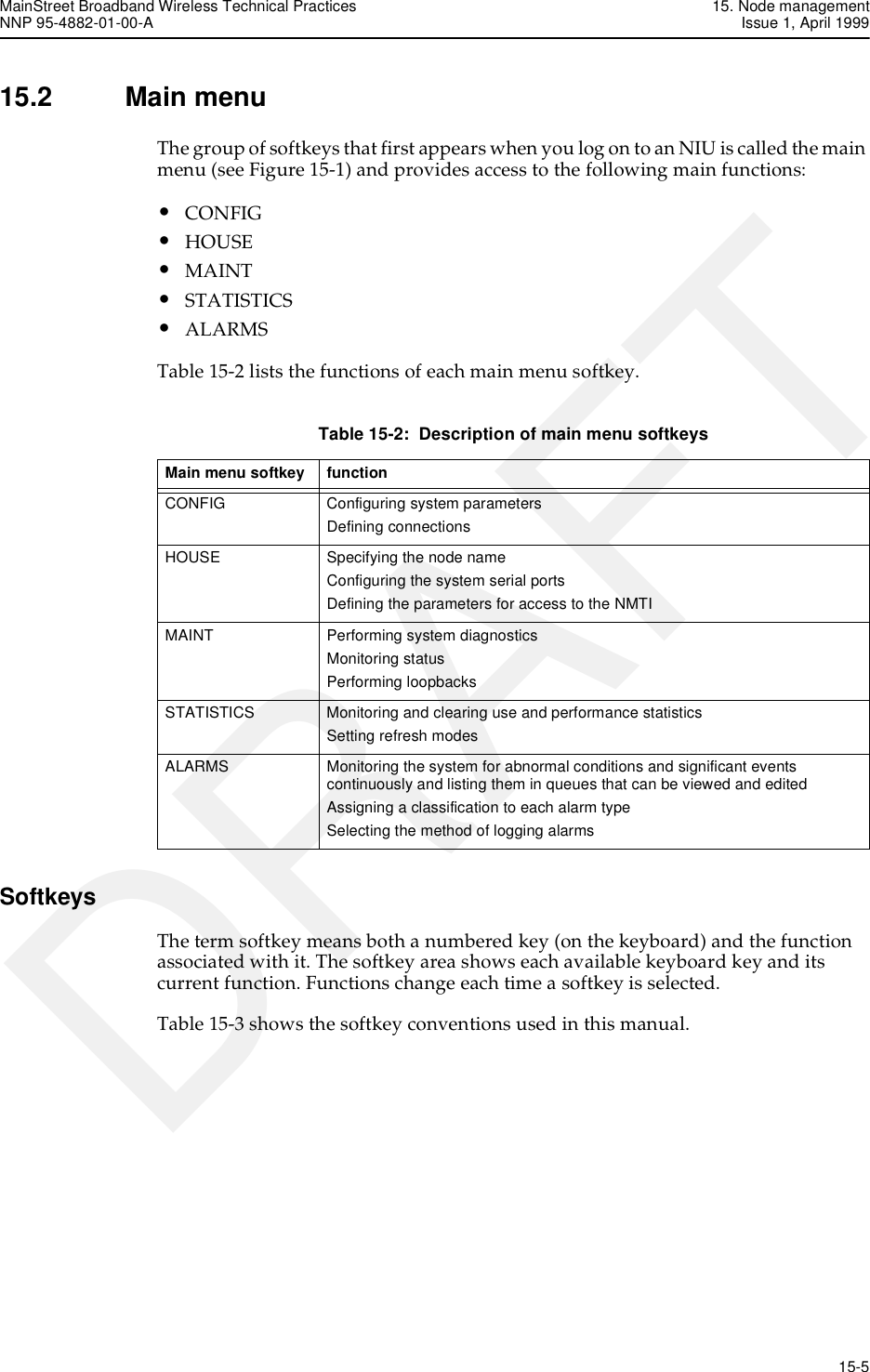
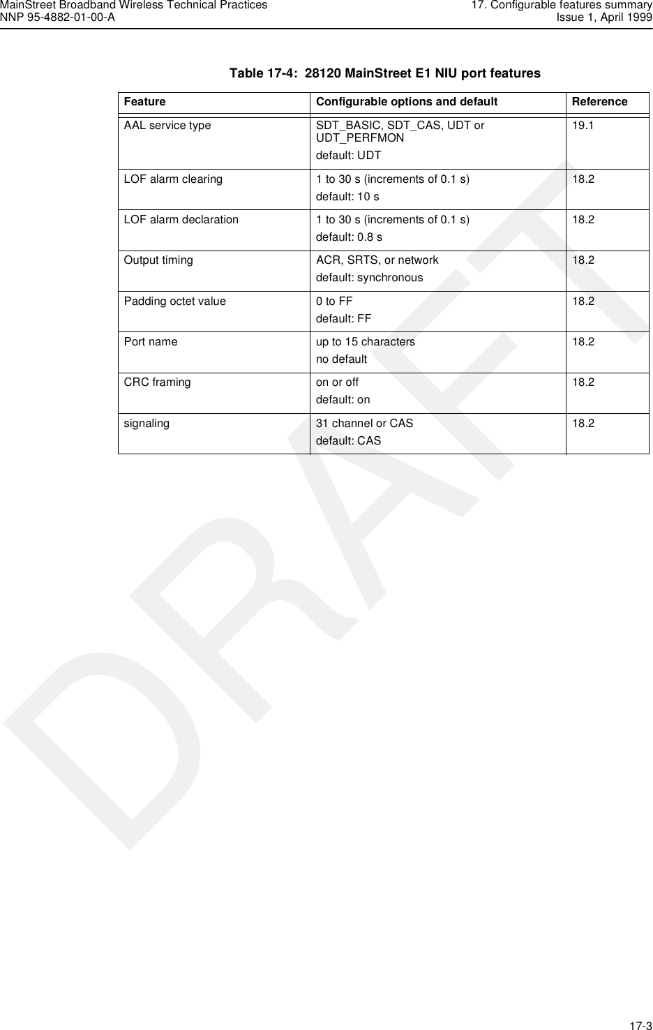
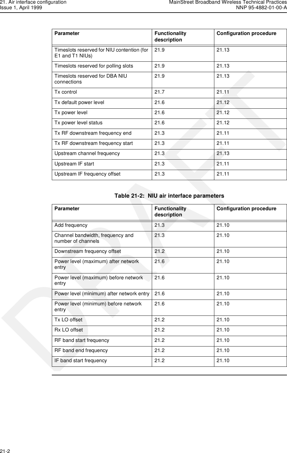
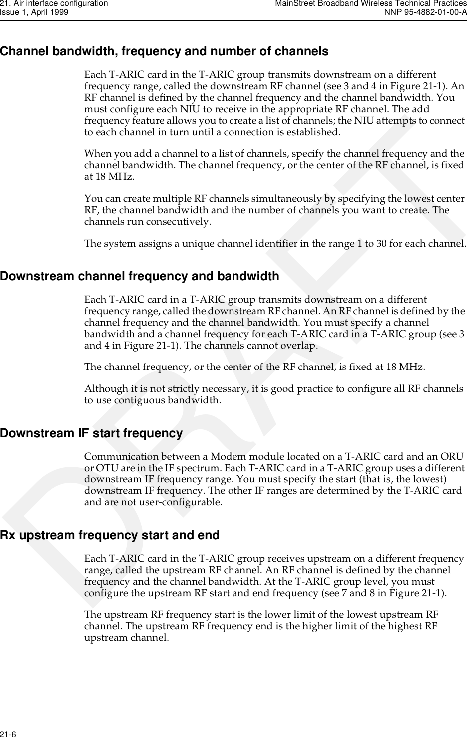
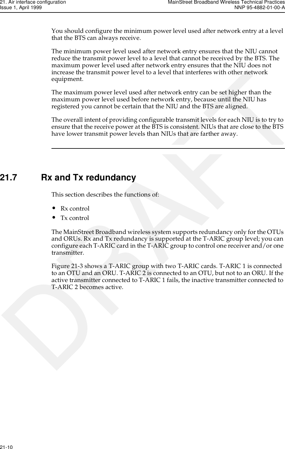
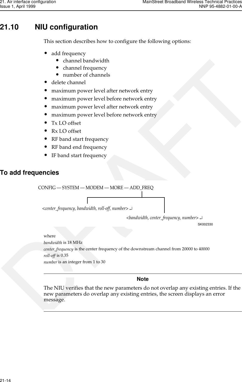
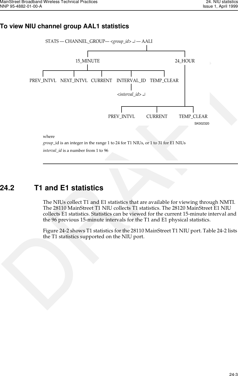
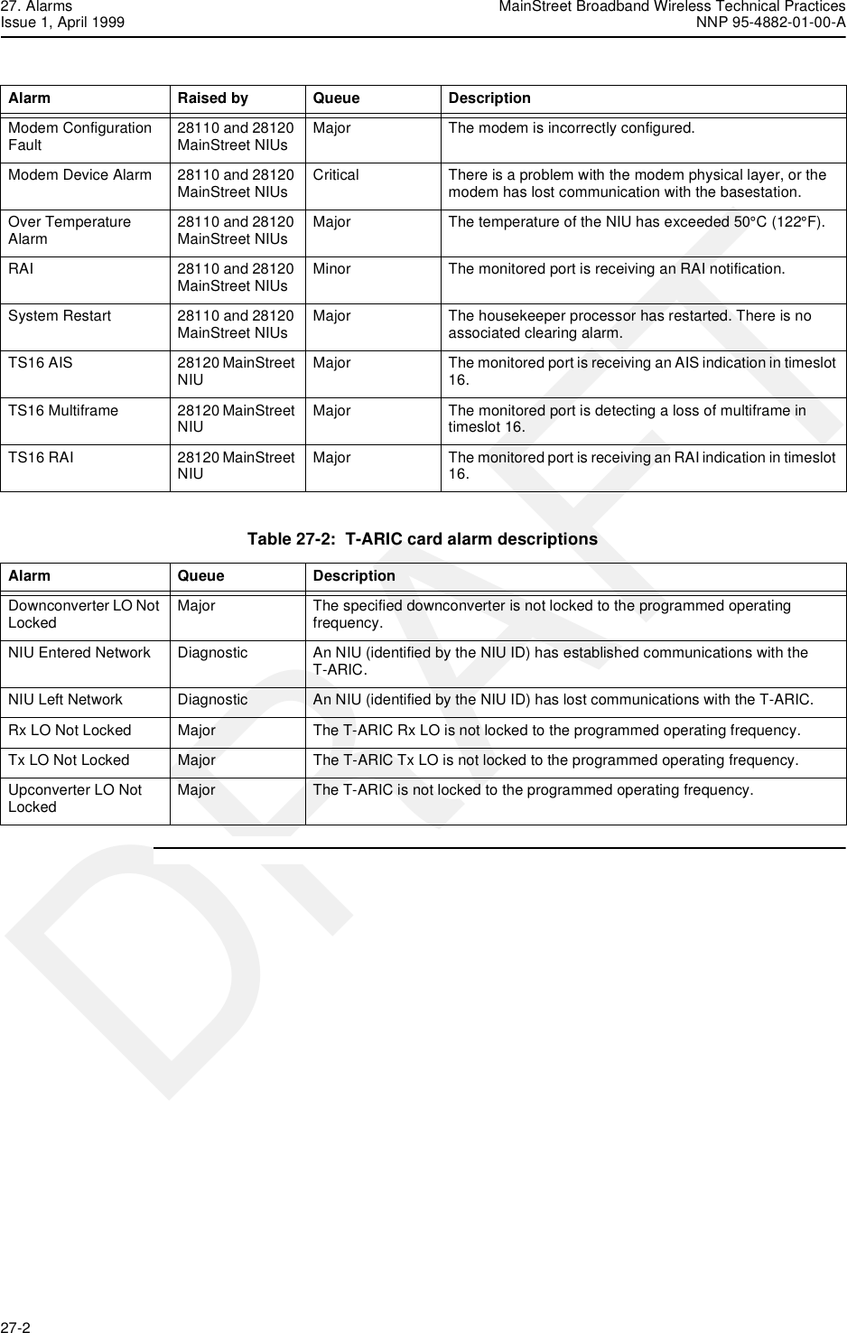
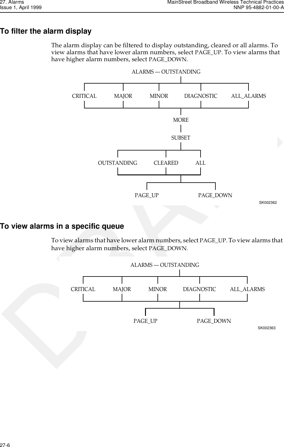
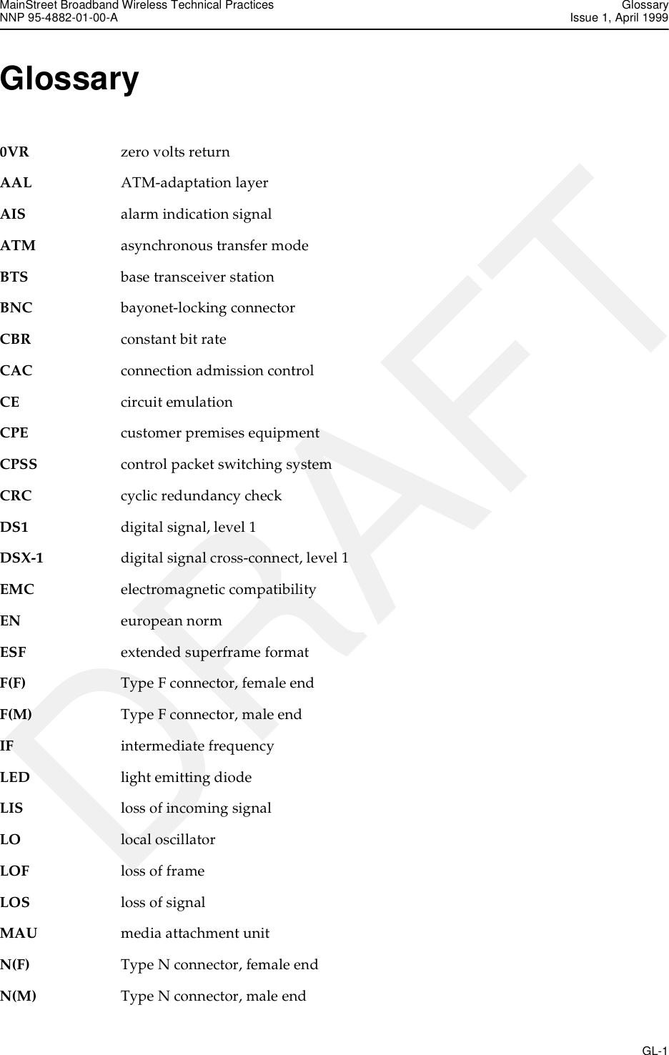
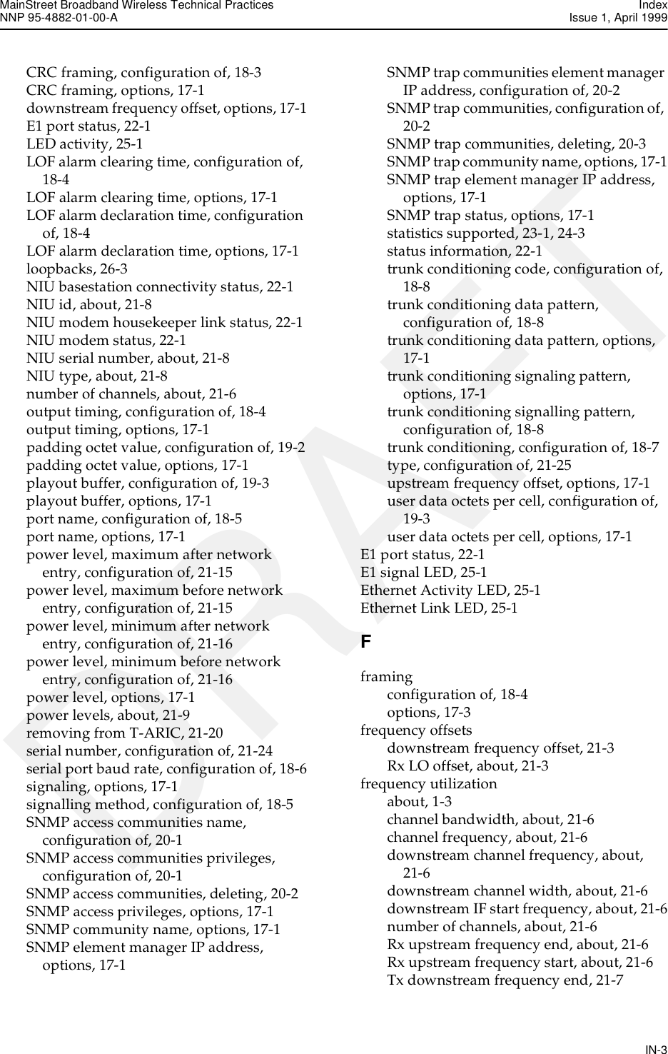
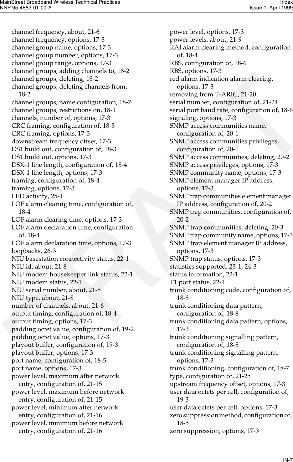
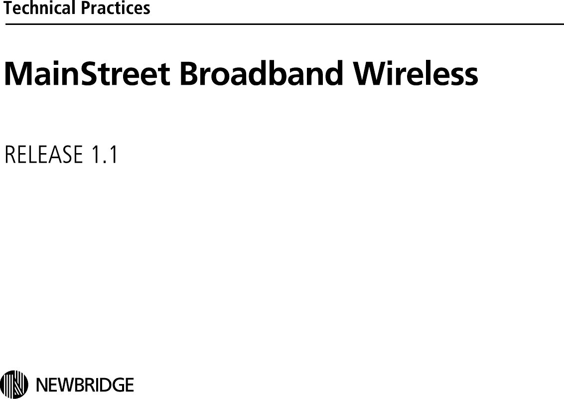
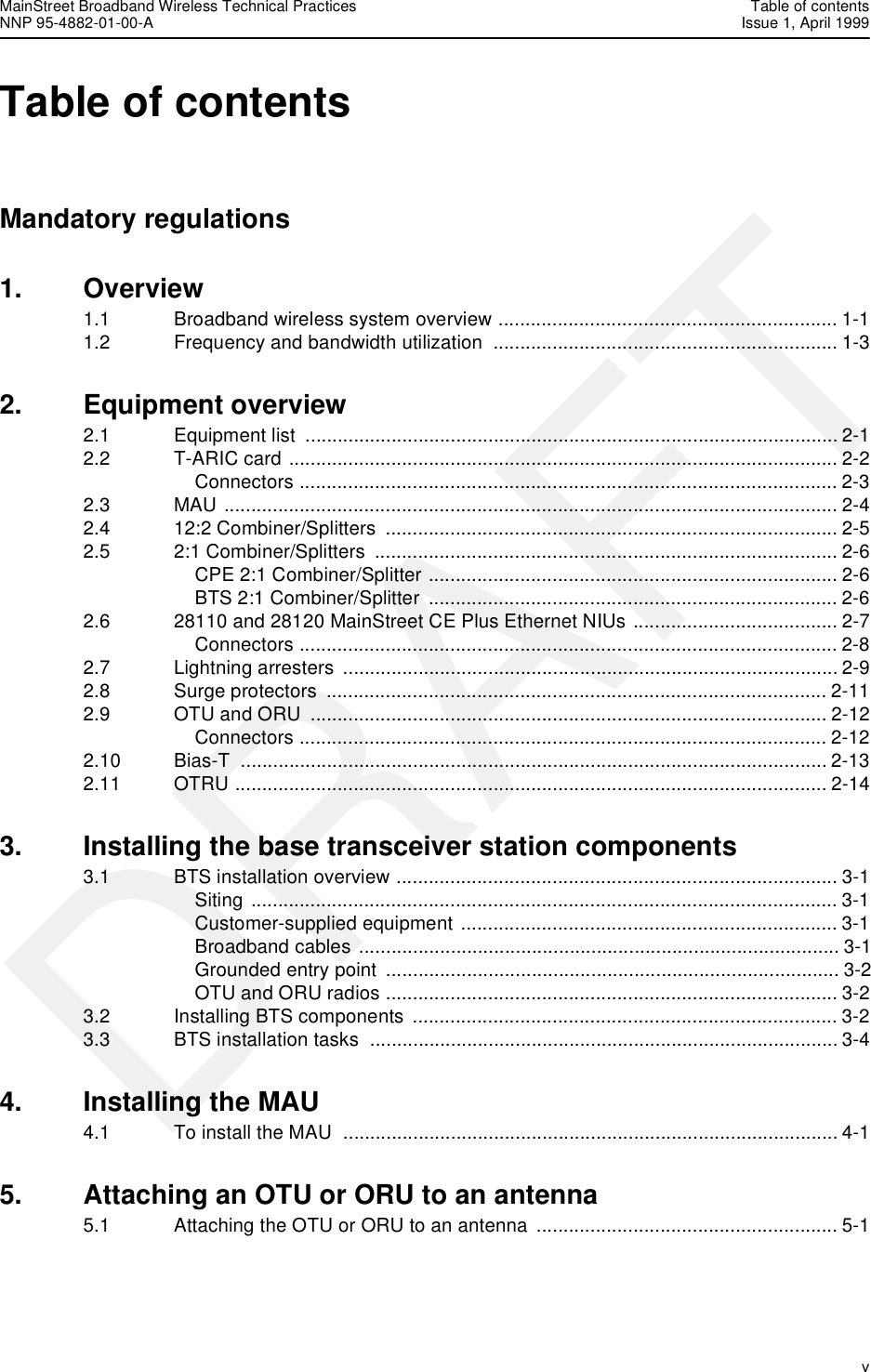
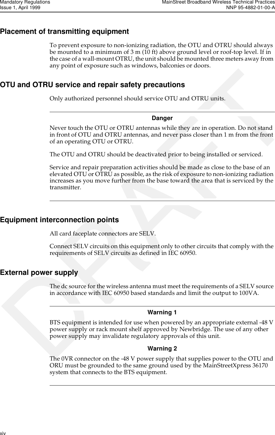
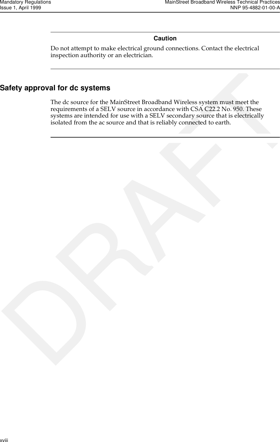
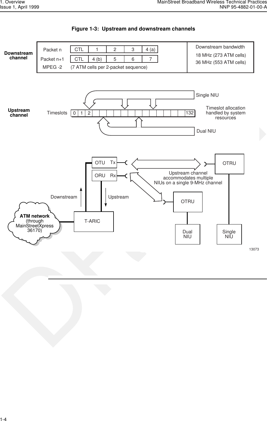
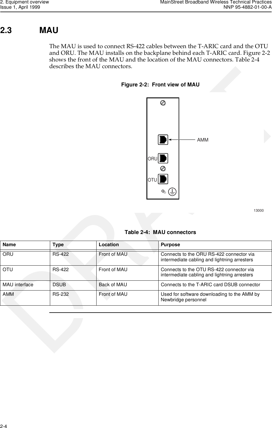
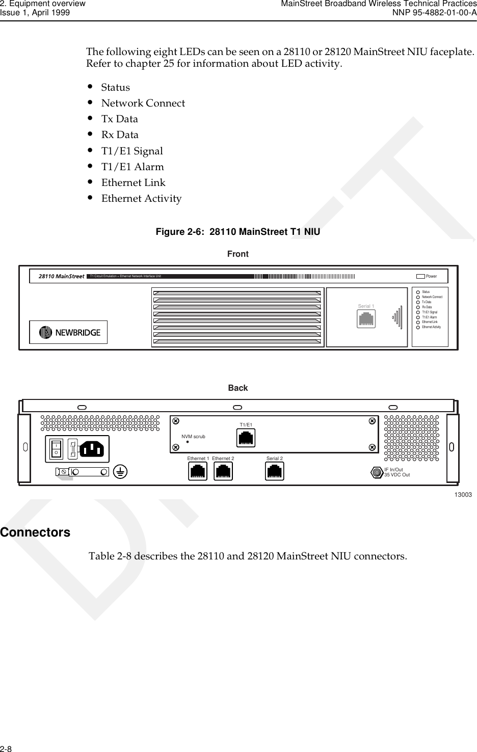
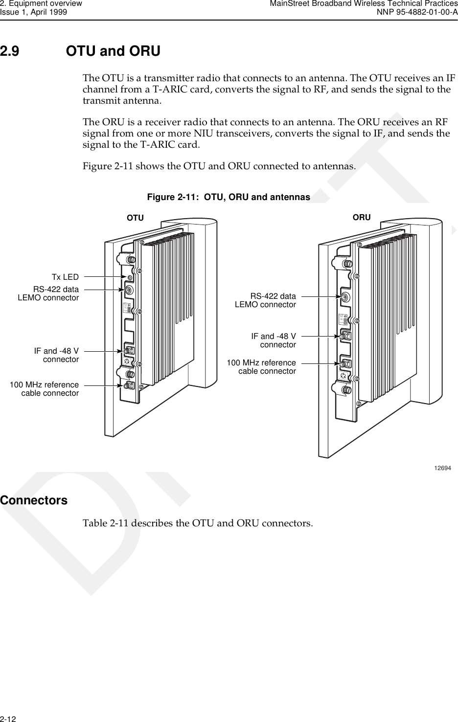
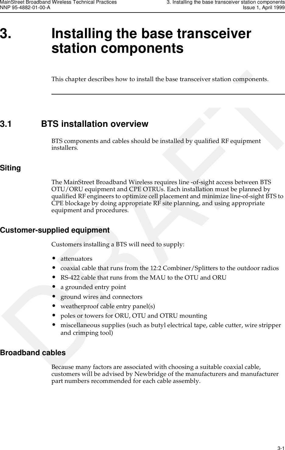
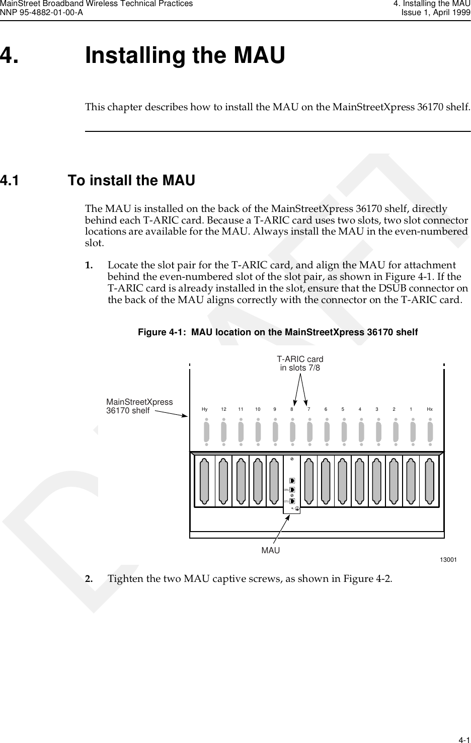
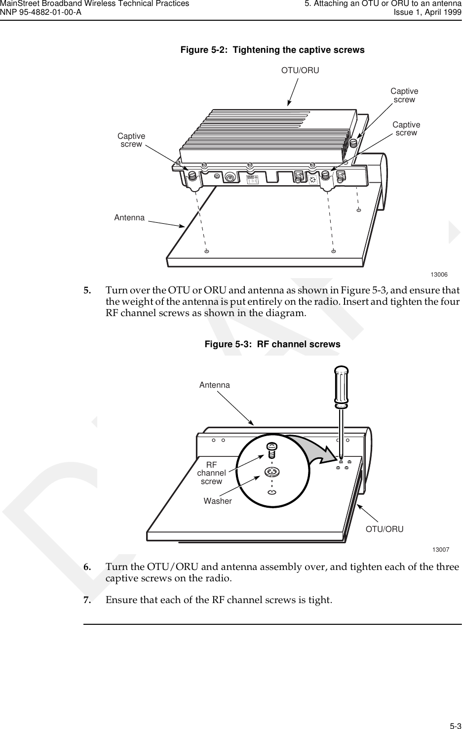
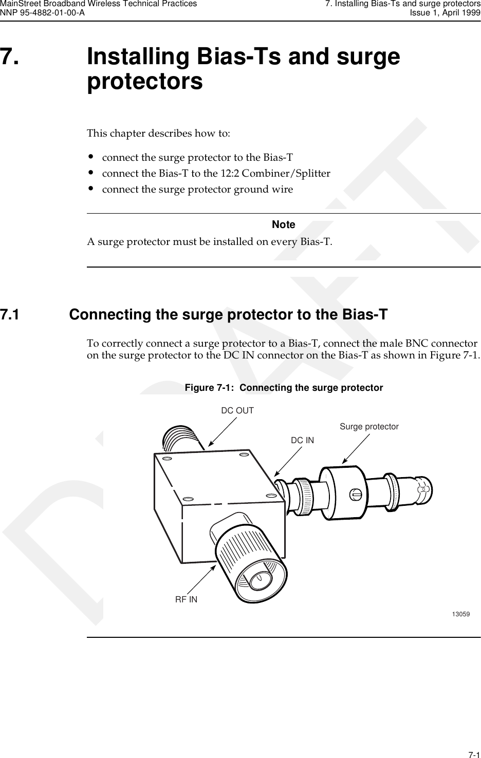
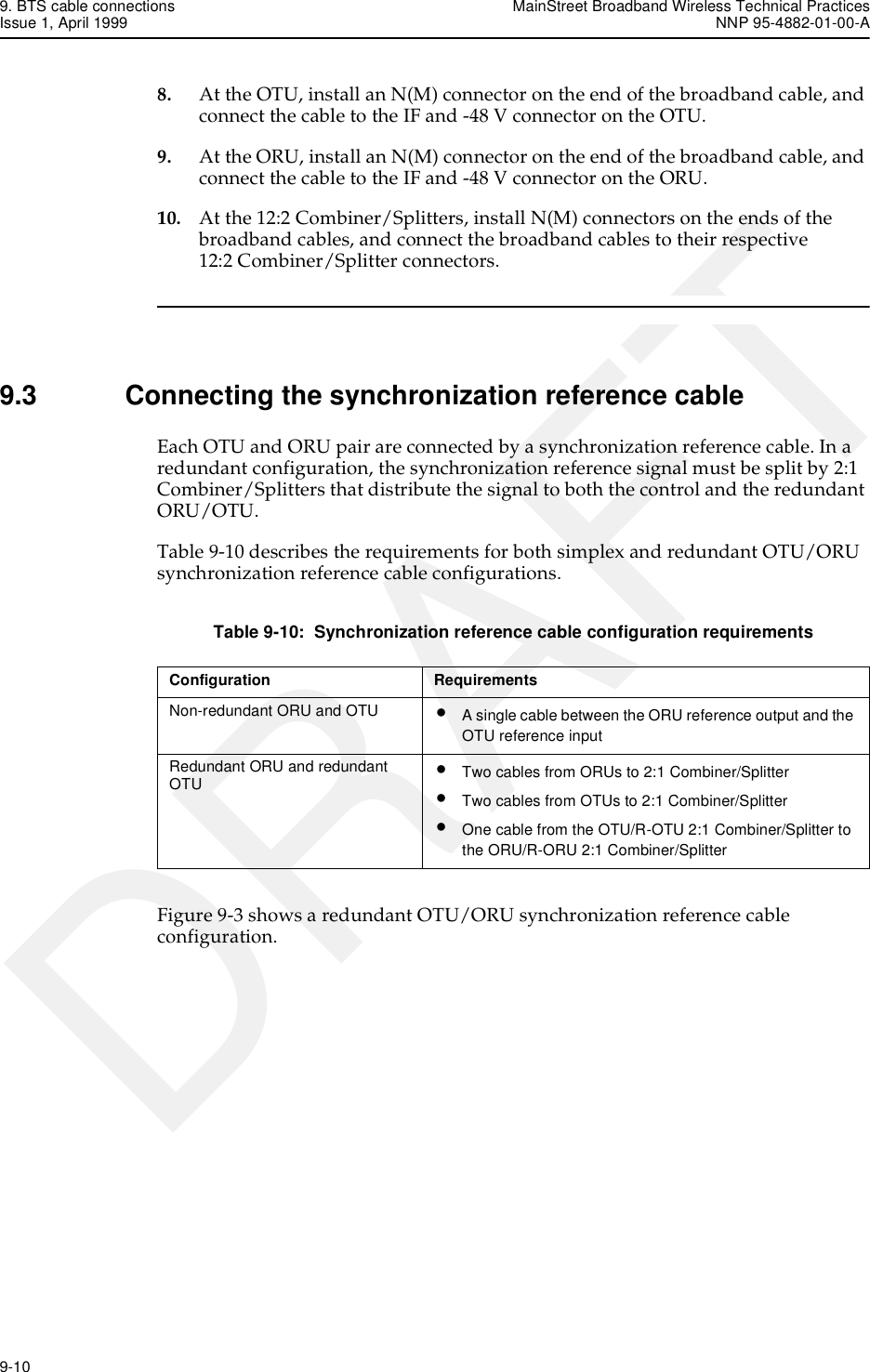
![MainStreet Broadband Wireless Technical Practices 9. BTS cable connectionsNNP 95-4882-01-00-A Issue 1, April 1999 9-5DRAFTTable 9-5: LDF5-50A cable (120 m [394 ft]) decibel loss calculationsBTS item MaxVSWR (x:1)Downstreamloss(2050 MHz)(dB)Upstreamloss(900 MHz)(dB)Downstreaminsertion andcoupling loss(2050 MHz)(dB)Upstreaminsertion andcoupling loss(900 MHz)(dB)DownstreamVSWR correctedloss (2050 MHz)(dB)UpstreamVSWR correctedloss (900 MHz)(dB)1 × T-ARIC SMA cable (3 m [10 ft]) 1.35 0.467 .333 1.40 1.00 1.46 1.051 × 12:2 OTU Combiner/Splitter 1.30 3.000 0.000 14.00 0.00 17.10 0.001 × 12:2 ORU Combiner/Splitter 1.30 0.000 2.500 0.00 14.00 0.00 16.591 × Bias-T 1.30 1.000 1.000 1.00 1.00 1.03 1.031 × surge protector 1.10 0.200 0.200 0.20 0.20 0.20 0.201 × cable LDF5-50A (120 m [394 ft])1.20 0.065 0.040 7.75 4.80 7.88 4.884 × cable connectors 1.20 0.200 0.200 0.80 0.80 0.94 0.94Total loss — — — 25.15 21.80 28.63 24.69](https://usermanual.wiki/Alcatel-Canada/28T36A06A11A/User-Guide-35880-Page-65.png)
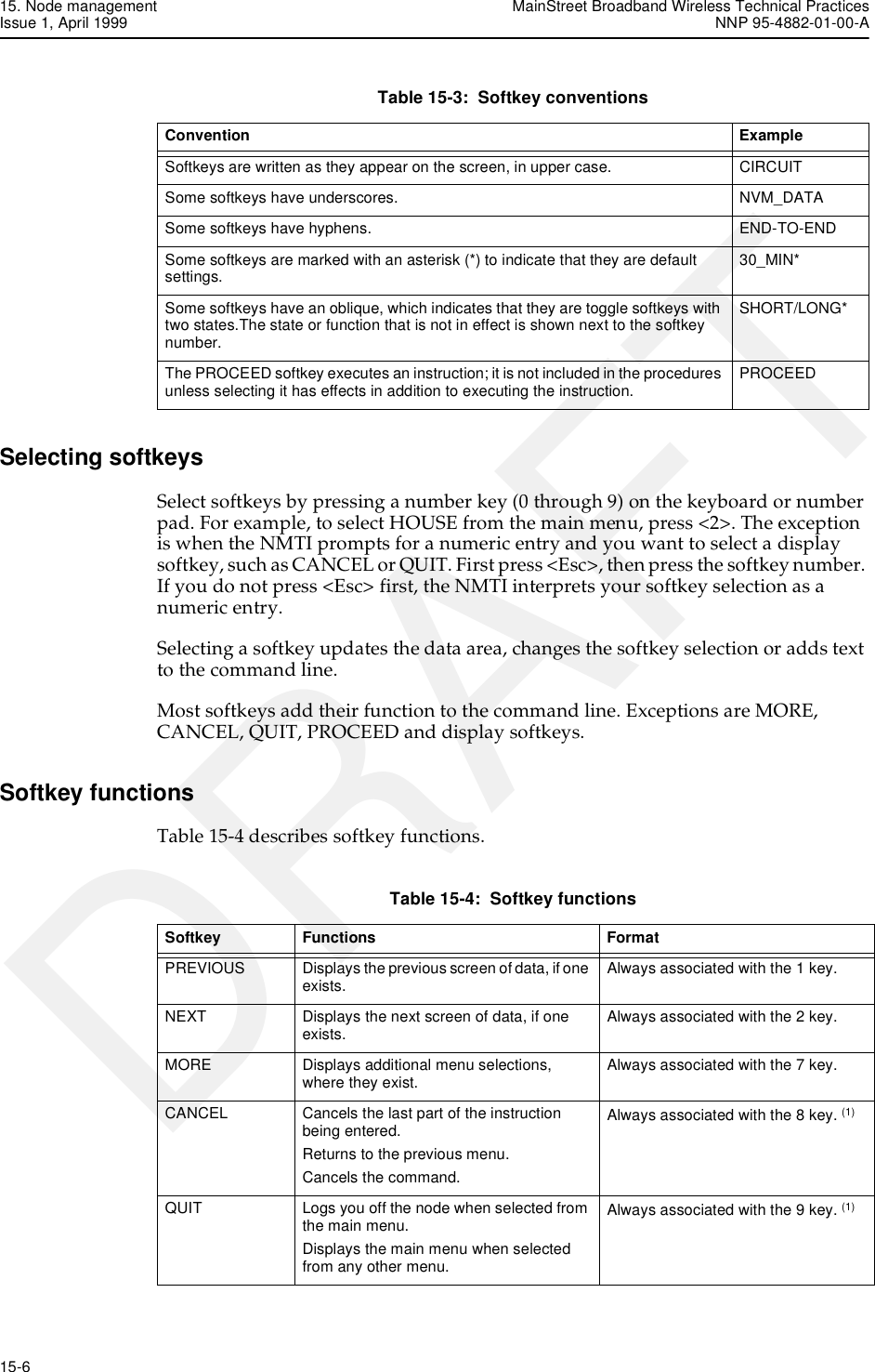
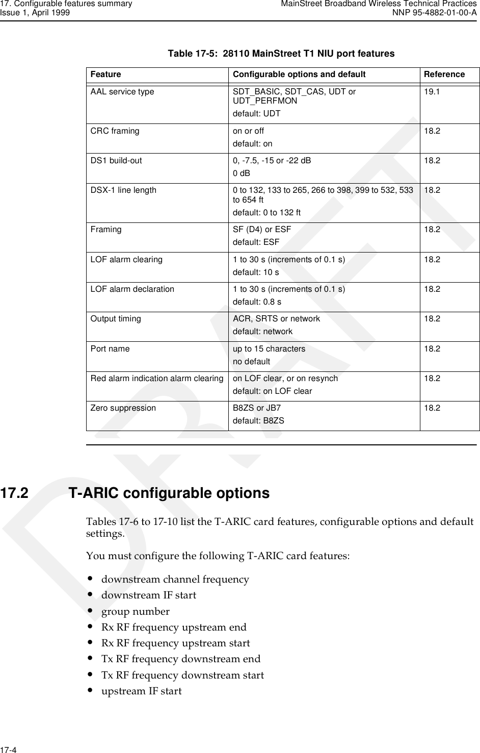
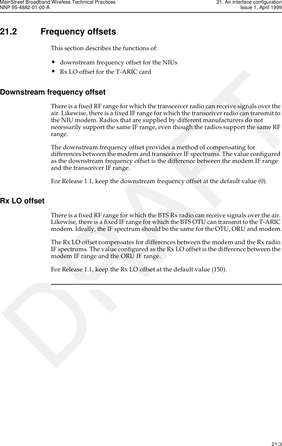
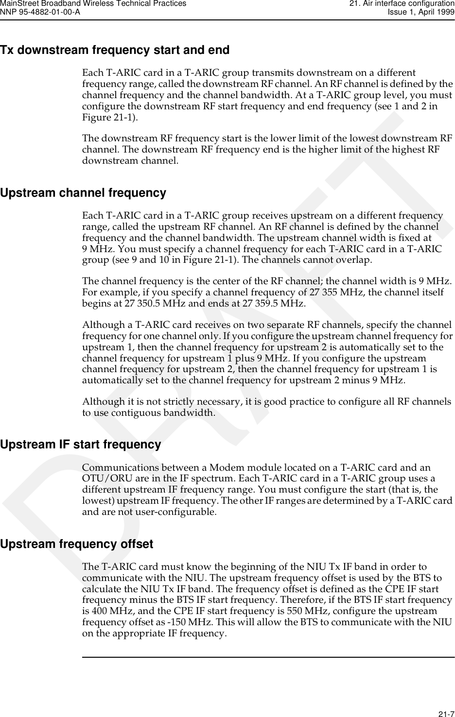
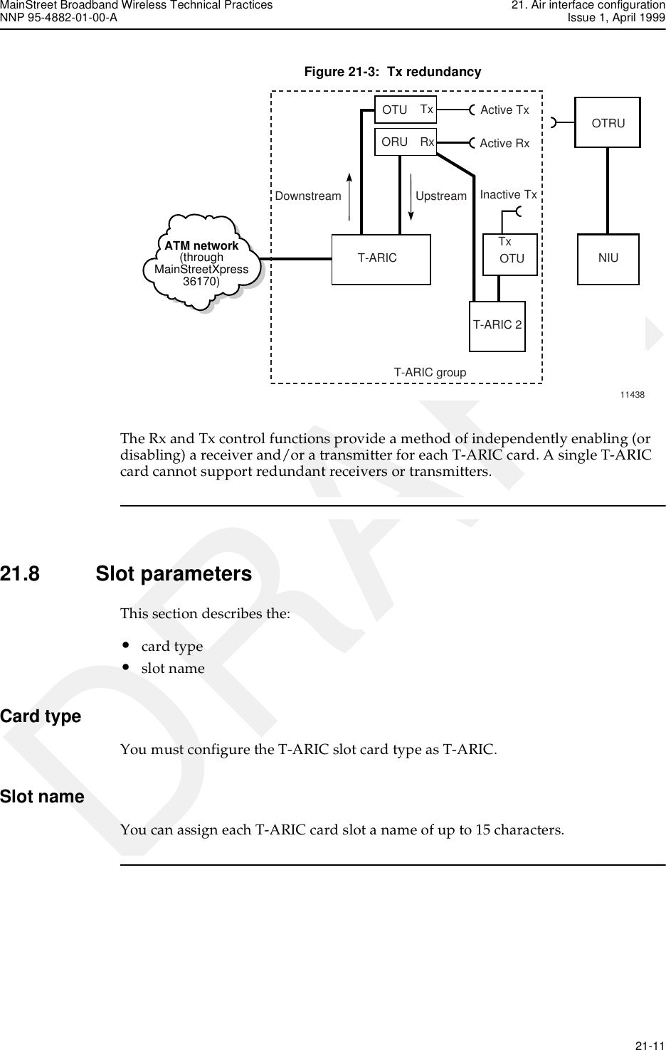
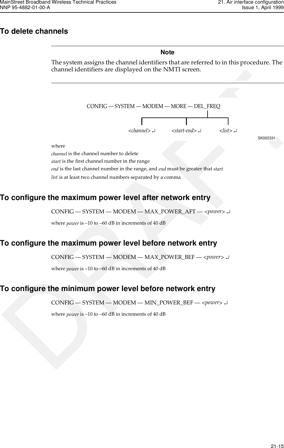
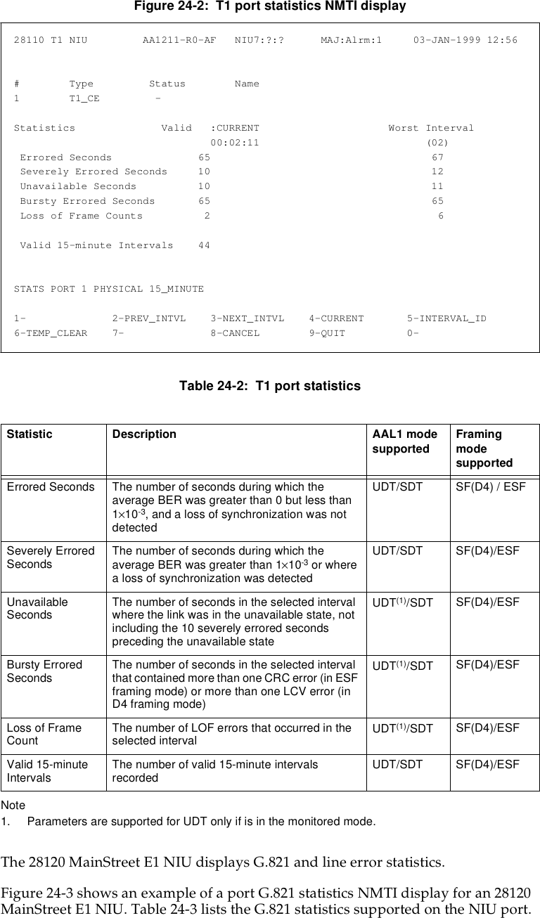
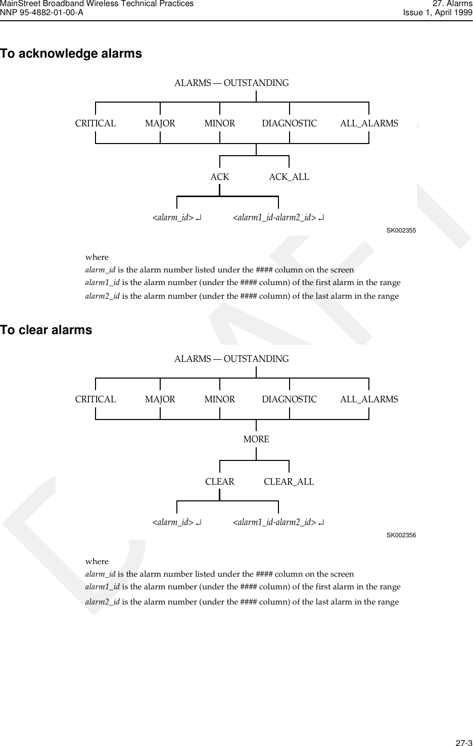
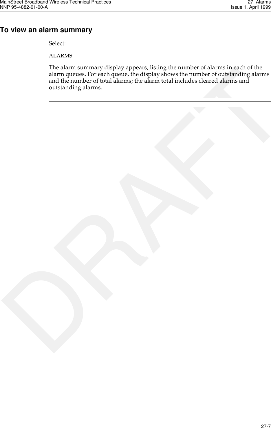
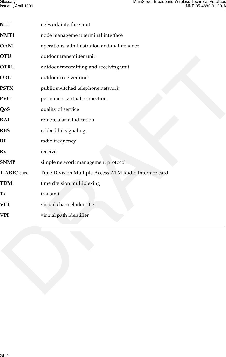
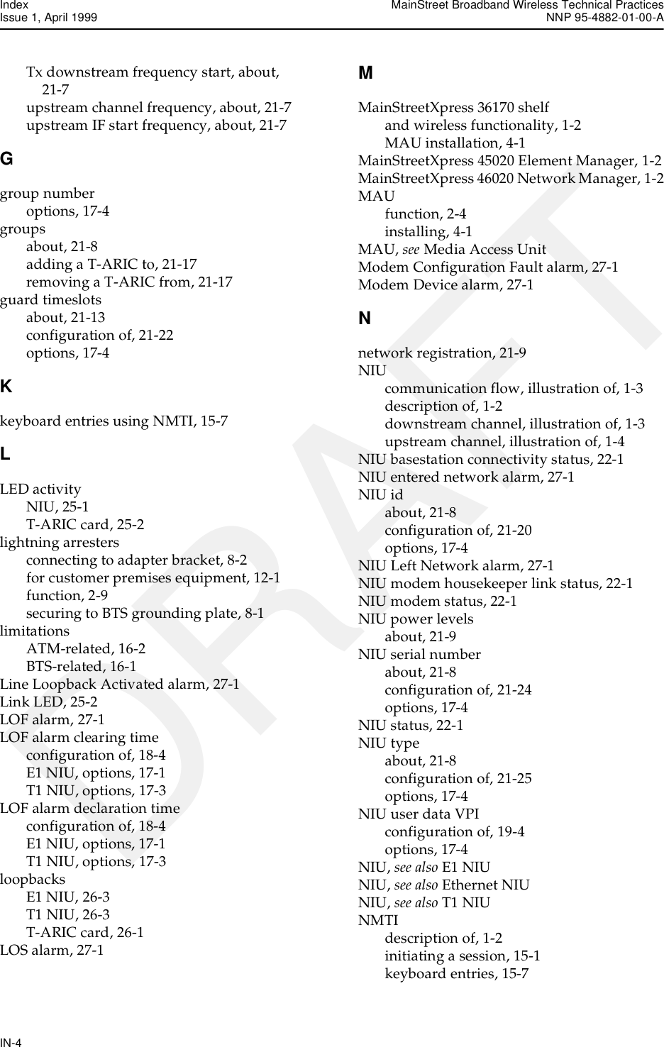
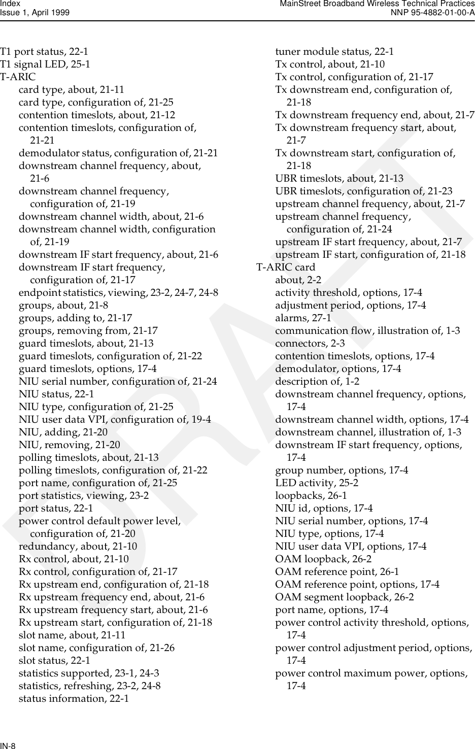
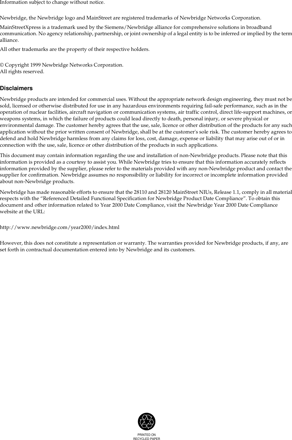
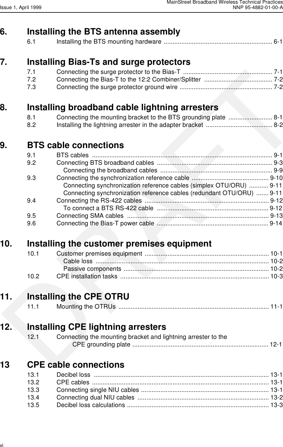
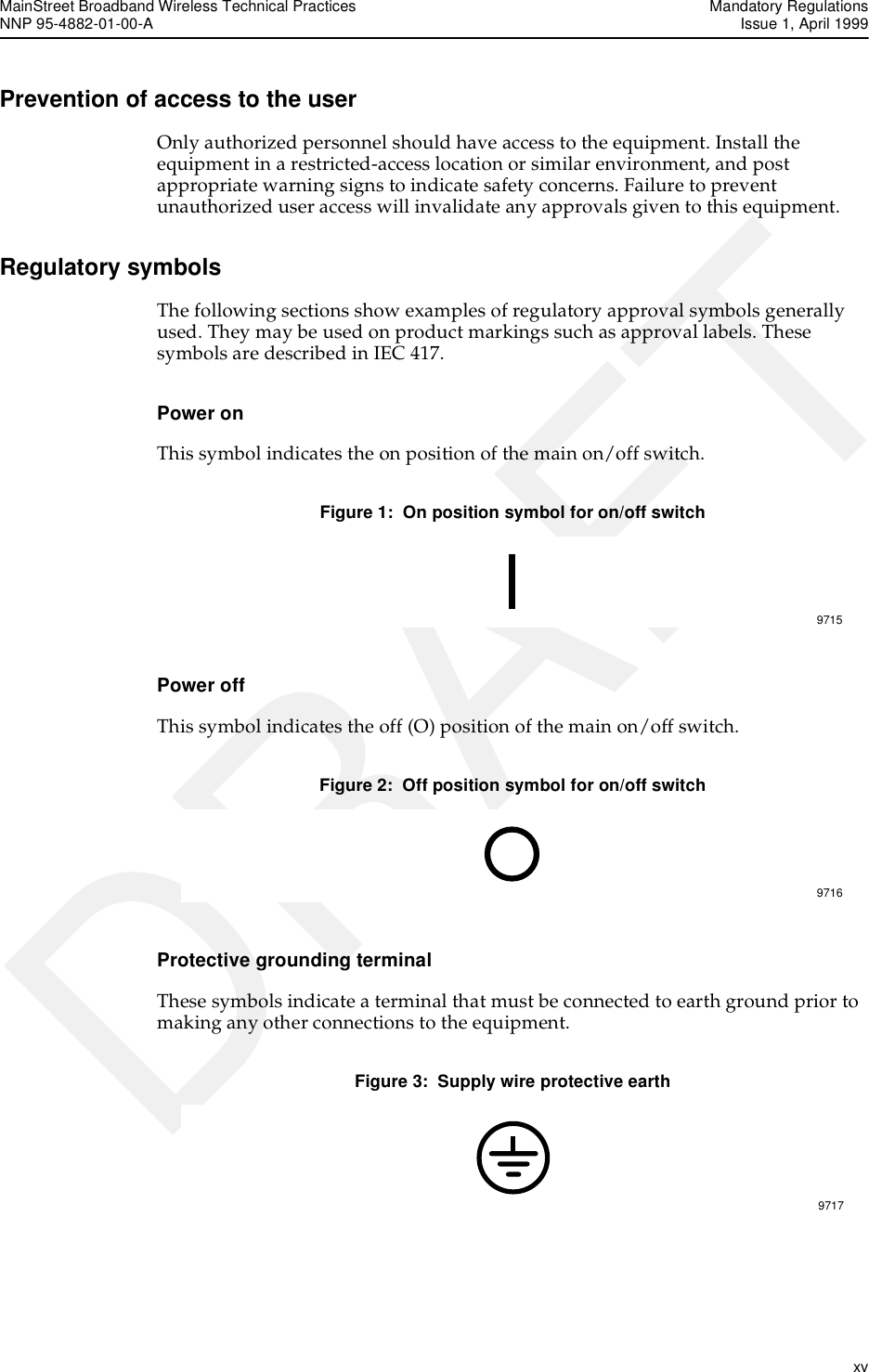
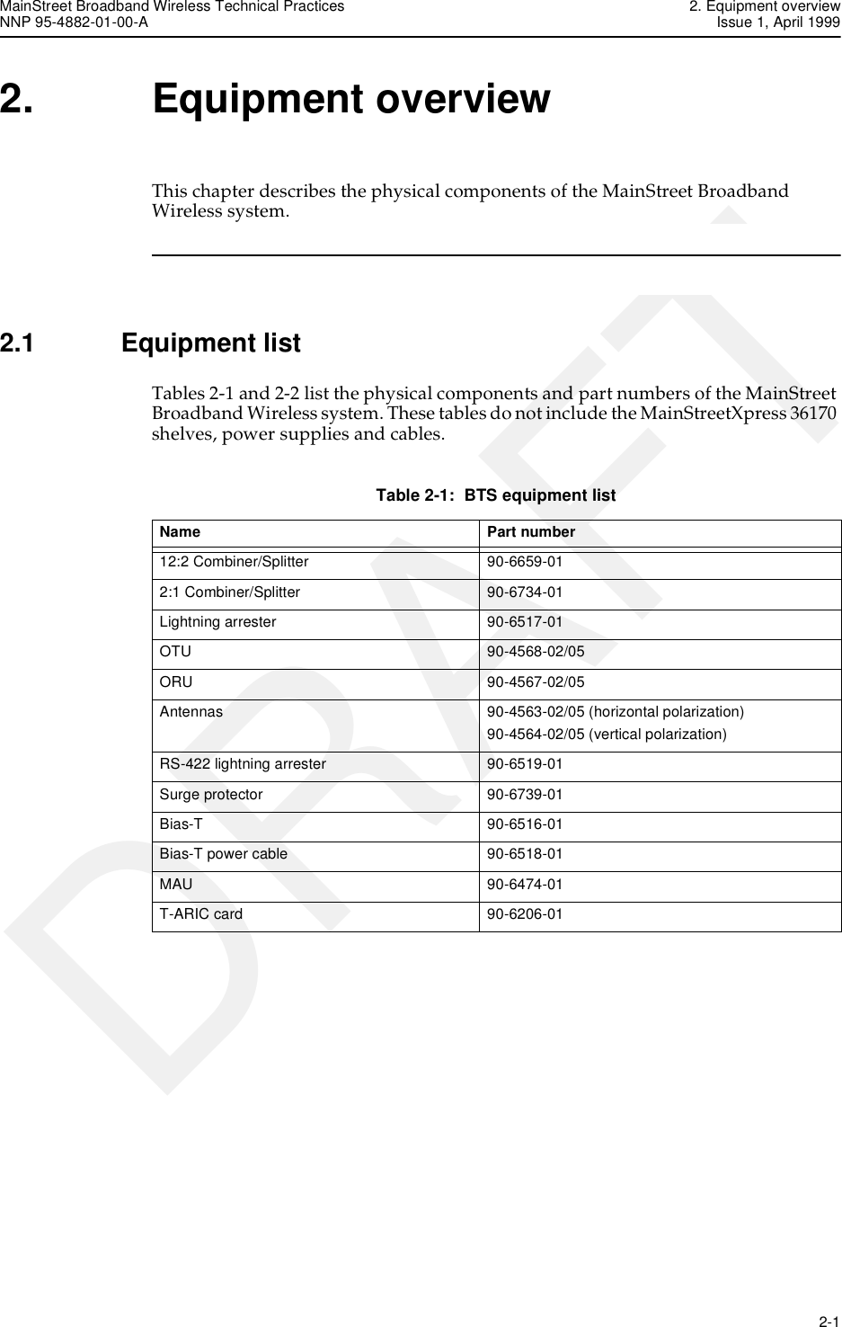
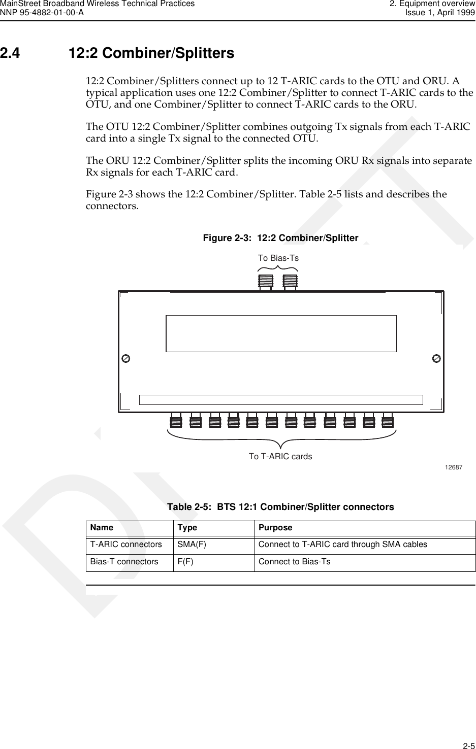
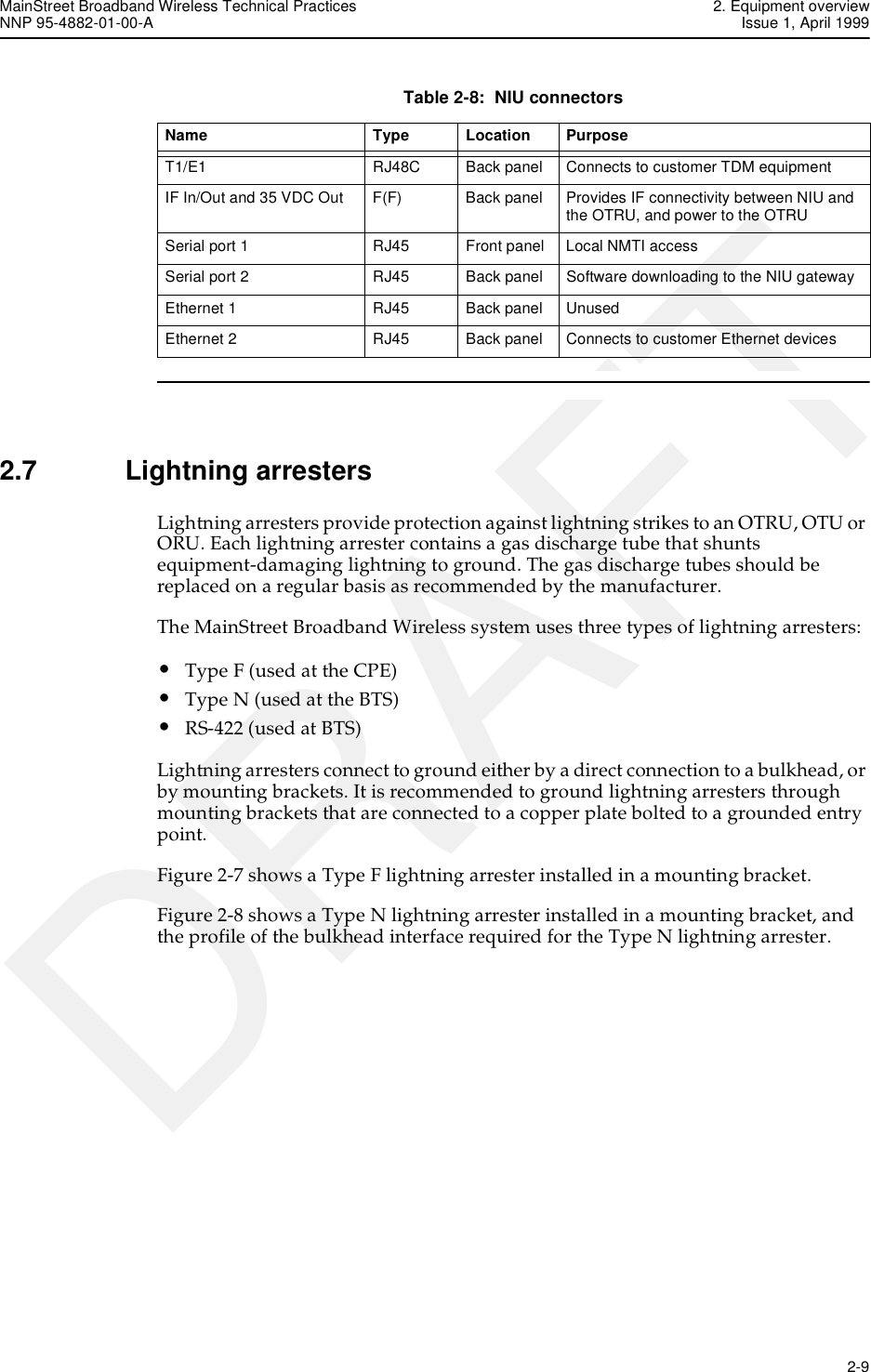
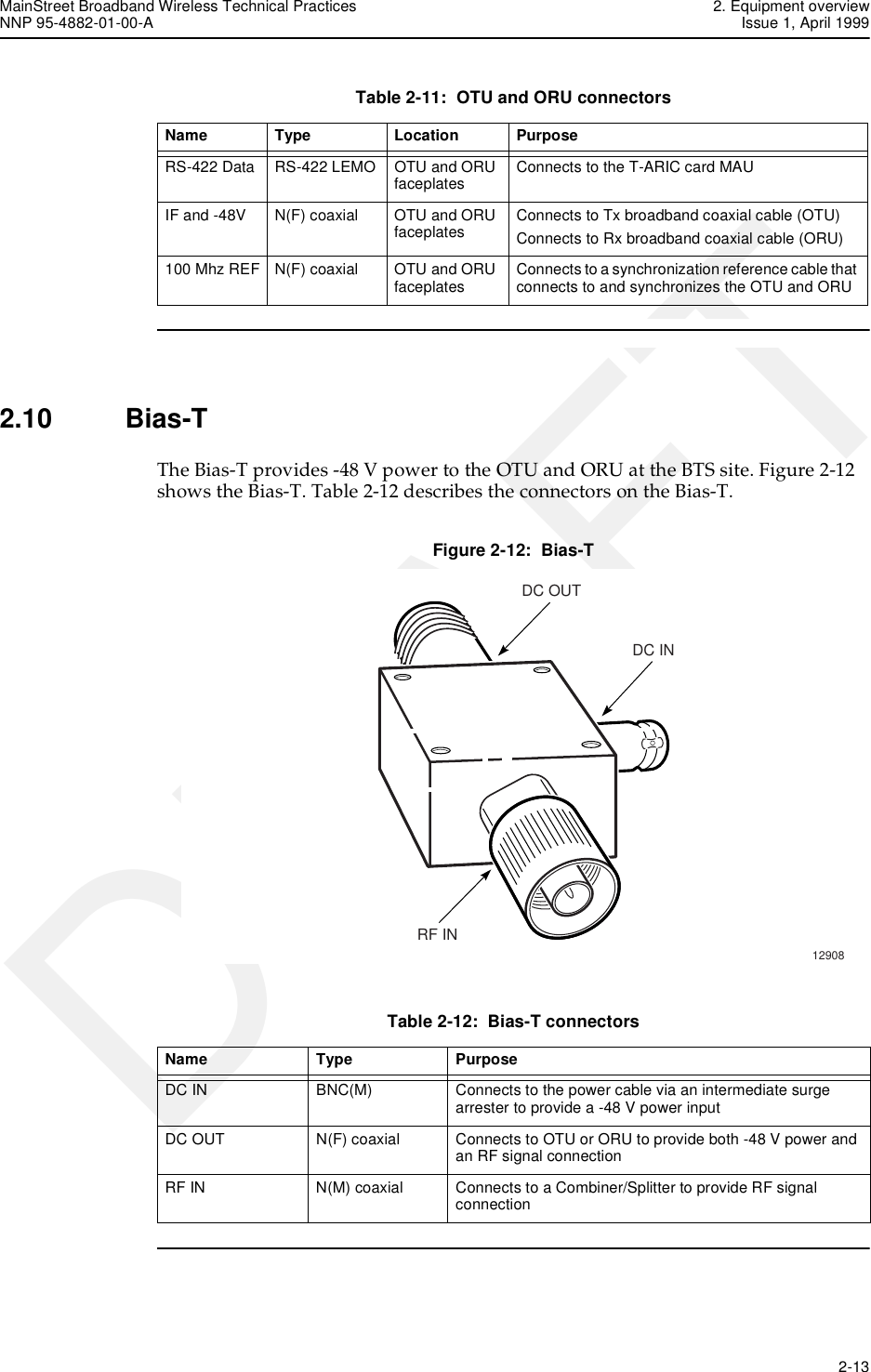
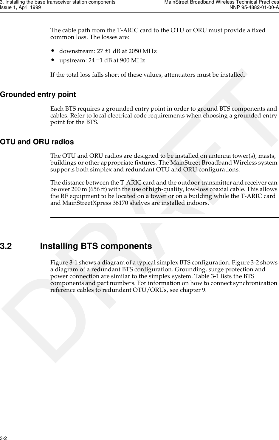
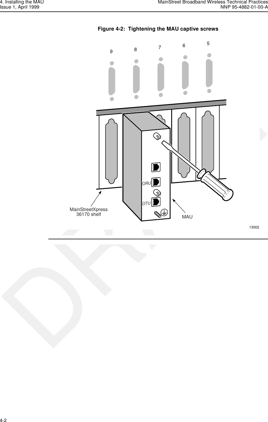
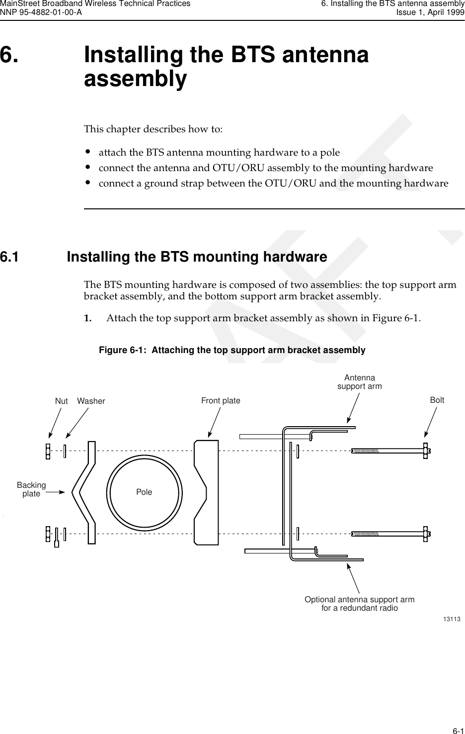
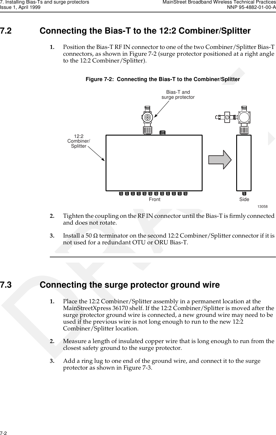
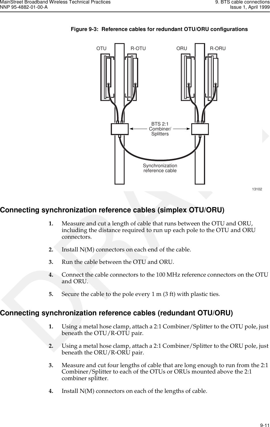
![9. BTS cable connections MainStreet Broadband Wireless Technical PracticesIssue 1, April 1999 NNP 95-4882-01-00-A9-6 DRAFTTable 9-6: LDF6-50A cable (150 m [492 ft]) decibel loss calculationsBTS item MaxVSWR (x:1)Downstreamloss(2050 MHz)(dB)Upstreamloss(900 MHz)(dB)Downstreaminsertion andcoupling loss(2050 MHz)(dB)Upstreaminsertion andcoupling loss(900 MHz)(dB)DownstreamVSWR correctedloss (2050 MHz)(dB)UpstreamVSWR correctedloss (900 MHz)(dB)1 × T-ARIC SMA cable (3m [10 ft]) 1.35 0.467 .333 1.40 1.00 1.46 1.051 × 12:2 OTU Combiner/Splitter 1.30 3.000 0.000 14.00 0.00 17.10 0.001 × 12:2 ORU Combiner/Splitter 1.30 0.000 2.500 0.00 14.00 0.00 16.591 × Bias-T 1.30 1.000 1.000 1.00 1.00 1.03 1.031 × surge protector 1.10 0.200 0.200 0.20 0.20 0.20 0.201 × cable LDF6-50A (150 m [492 ft])1.20 0.065 0.040 7.75 4.80 7.88 4.884 × cable connectors 1.20 0.200 0.200 0.80 0.80 0.94 0.94Total loss — — — 25.15 21.80 28.63 24.69](https://usermanual.wiki/Alcatel-Canada/28T36A06A11A/User-Guide-35880-Page-66.png)
![MainStreet Broadband Wireless Technical Practices 9. BTS cable connectionsNNP 95-4882-01-00-A Issue 1, April 1999 9-7DRAFTTable 9-7: CR50-540-PE cable (70 m [230 ft]) decibel loss calculationsBTS item MaxVSWR (x:1)Downstreamloss(2050 MHz)(dB)Upstreamloss(900 MHz)(dB)Downstreaminsertion andcoupling loss(2050 MHz)(dB)Upstreaminsertion andcoupling loss(900 MHz)(dB)DownstreamVSWR correctedloss (2050 MHz)(dB)UpstreamVSWR correctedloss (900 MHz)(dB)1 × T-ARIC SMA cable (3m [10 ft]) 1.35 0.467 .333 1.40 1.00 1.46 1.051 × 12:2 OTU Combiner/Splitter 1.30 3.000 0.000 14.00 0.00 17.10 0.001 × 12:2 ORU Combiner/Splitter 1.30 0.000 2.500 0.00 14.00 0.00 16.591 × Bias-T 1.30 1.000 1.000 1.00 1.00 1.03 1.031 × surge protector 1.10 0.200 0.200 0.20 0.20 0.20 0.201 × cable CR50-540-PE(70 m [230 ft])1.20 0.065 0.040 7.75 4.80 7.88 4.884 × cable connectors 1.20 0.200 0.200 0.80 0.80 0.94 0.94Total loss — — — 25.15 21.80 28.63 24.69](https://usermanual.wiki/Alcatel-Canada/28T36A06A11A/User-Guide-35880-Page-67.png)
![9. BTS cable connections MainStreet Broadband Wireless Technical PracticesIssue 1, April 1999 NNP 95-4882-01-00-A9-8 DRAFTTable 9-8: CR50-1070-PE cable (120 m [394 ft]) decibel loss calculationsBTS item MaxVSWR (x:1)Downstreamloss(2050 MHz)(dB)Upstreamloss(900 MHz)(dB)Downstreaminsertion andcoupling loss(2050 MHz)(dB)Upstreaminsertion andcoupling loss(900 MHz)(dB)DownstreamVSWR correctedloss (2050 MHz)(dB)UpstreamVSWR correctedloss (900 MHz)(dB)1 × T-ARIC SMA cable (3m [10 ft]) 1.35 0.467 .333 1.40 1.00 1.46 1.051 × 12:2 OTU Combiner/Splitter 1.30 3.000 0.000 14.00 0.00 17.10 0.001 × 12:2 ORU Combiner/Splitter 1.30 0.000 2.500 0.00 14.00 0.00 16.591 × Bias-T 1.30 1.000 1.000 1.00 1.00 1.03 1.031 × surge protector 1.10 0.200 0.200 0.20 0.20 0.20 0.201 × cable CR50-1070-PE(120 m [394 ft])1.20 0.065 0.040 7.75 4.80 7.88 4.884 × cable connectors 1.20 0.200 0.200 0.80 0.80 0.94 0.94Total loss — — — 25.15 21.80 28.63 24.69](https://usermanual.wiki/Alcatel-Canada/28T36A06A11A/User-Guide-35880-Page-68.png)
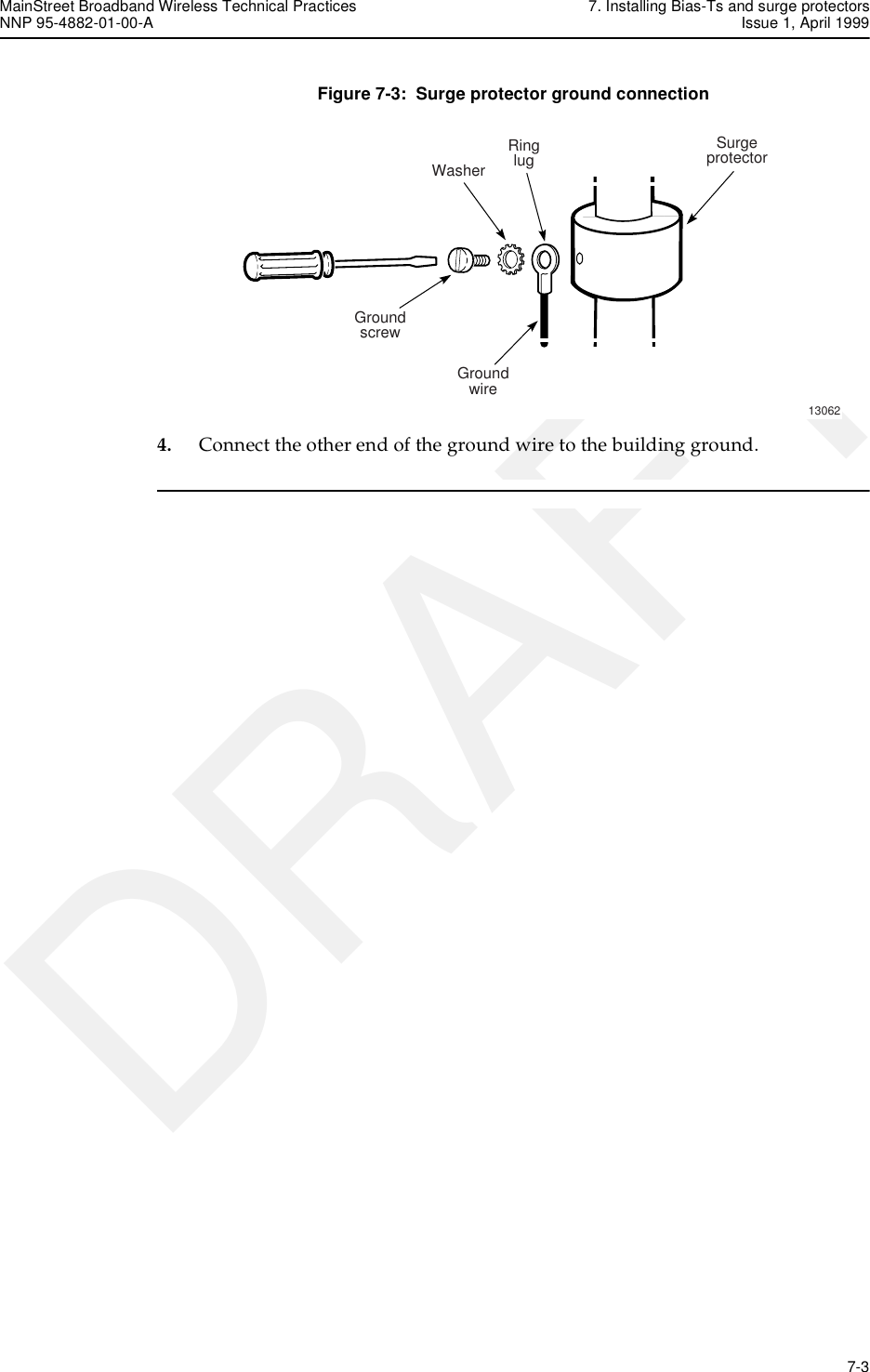
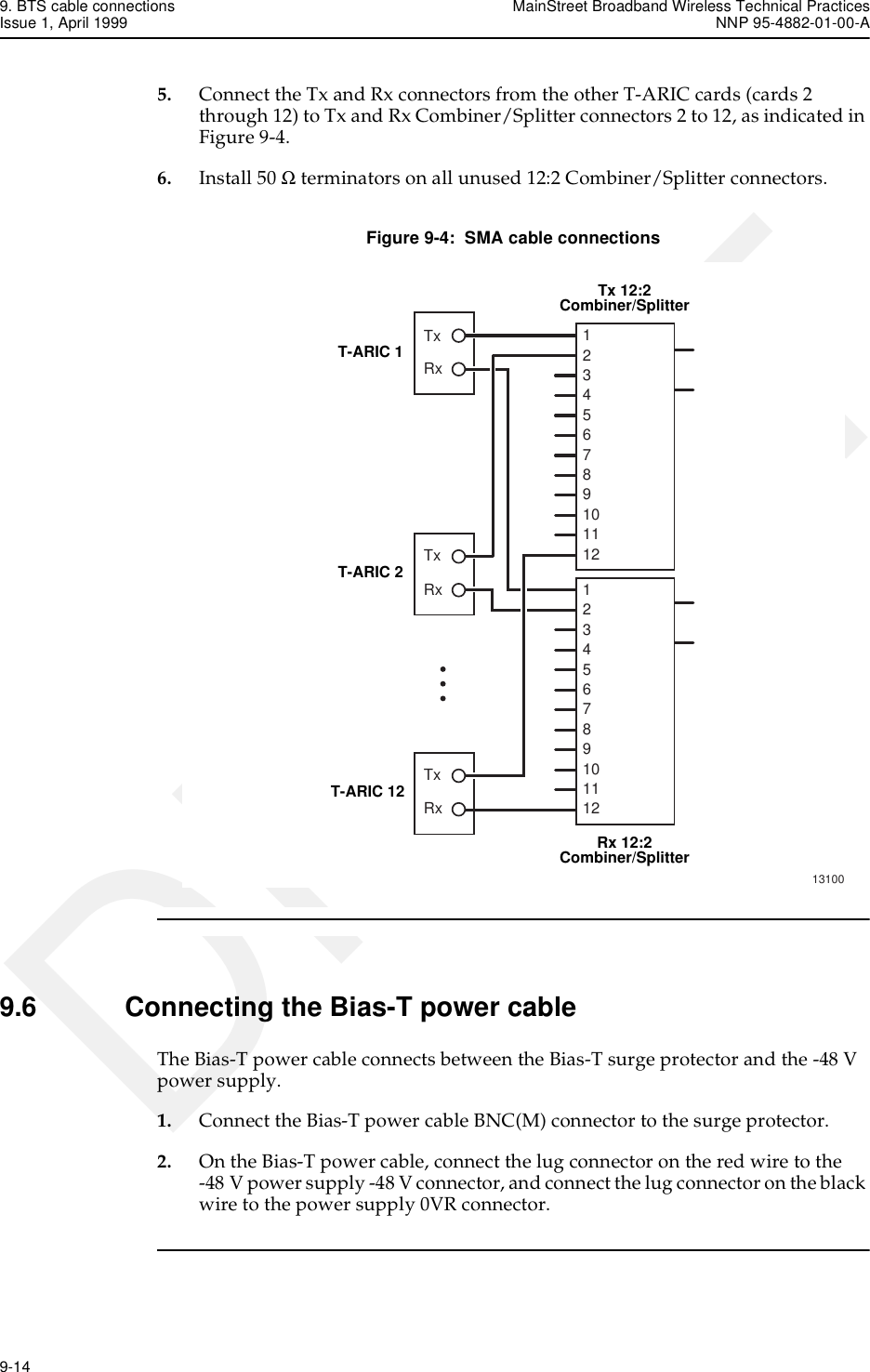
![MainStreet Broadband Wireless Technical Practices 9. BTS cable connectionsNNP 95-4882-01-00-A Issue 1, April 1999 9-9DRAFTTable 9-9: CR50-1873-PE cable (200 m [656 ft]) decibel loss calculationsConnecting the broadband cables1. Determine the cable length required for the distance between the OTU/ORU assembly and the T-ARIC card.2. Use Table 9-3 to select a cable type based on the required length. If non-Newbridge components are used, use Tables 9-4 to 9-9 to ensure that the fixed dB loss is maintained.3. Secure the OTU and ORU broadband cables to the respective poles or towers with a cable tie, leaving enough length to connect the cables to the elevated OTU and ORU positions.4. Feed the cables through the weatherproof access panel to the grounded entry point where the lightning arresters are installed. Secure the cables to the grounded entry point, and continue to feed the cables to the location of the 12:2 Combiner/Splitters.5. Secure the end of the cables to a location near the 12:2 Combiner/Splitters, after ensuring that the cables are long enough to reach and connect to the 12:2 Combiner/Splitters.6. At the grounded entry point, cut each cable to a length sufficient to allow the ends of both cables to connect to the lightning arresters.7. Install the N(M) connectors on the cables, and mate the cables to the lightning arresters, as indicated in Figures 9-1 or 9-2.BTS item MaxVSWR (x:1)Downstreamloss(2050 MHz)(dB)Upstreamloss(900 MHz)(dB)Downstreaminsertion andcoupling loss(2050 MHz)(dB)Upstreaminsertion andcoupling loss(900 MHz)(dB)DownstreamVSWR correctedloss (2050 MHz)(dB)UpstreamVSWR correctedloss (900 MHz)(dB)1 × T-ARIC SMA cable (3m [10 ft]) 1.35 0.467 .333 1.40 1.00 1.46 1.051 × 12:2 OTU Combiner/Splitter 1.30 3.000 0.000 14.00 0.00 17.10 0.001 × 12:2 ORU Combiner/Splitter 1.30 0.000 2.500 0.00 14.00 0.00 16.591 × Bias-T 1.30 1.000 1.000 1.00 1.00 1.03 1.031 × surge protector 1.10 0.200 0.200 0.20 0.20 0.20 0.201 × cable CR50-1873-PE(200 m [656 ft])1.20 0.065 0.040 7.75 4.80 7.88 4.884 × cable connectors 1.20 0.200 0.200 0.80 0.80 0.94 0.94Total loss — — — 25.15 21.80 28.63 24.69](https://usermanual.wiki/Alcatel-Canada/28T36A06A11A/User-Guide-35880-Page-69.png)
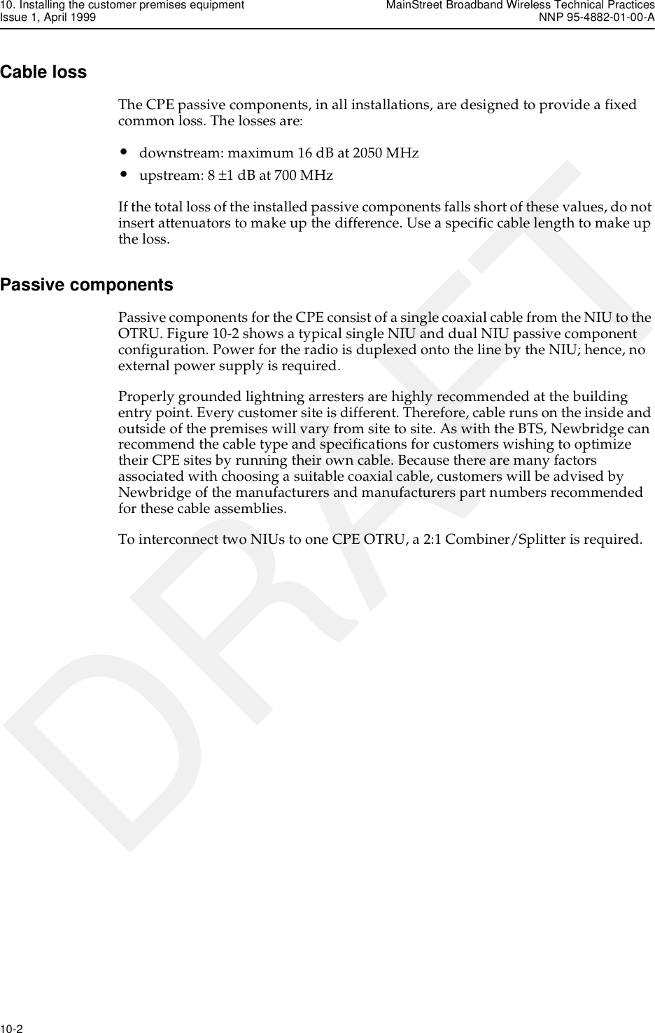
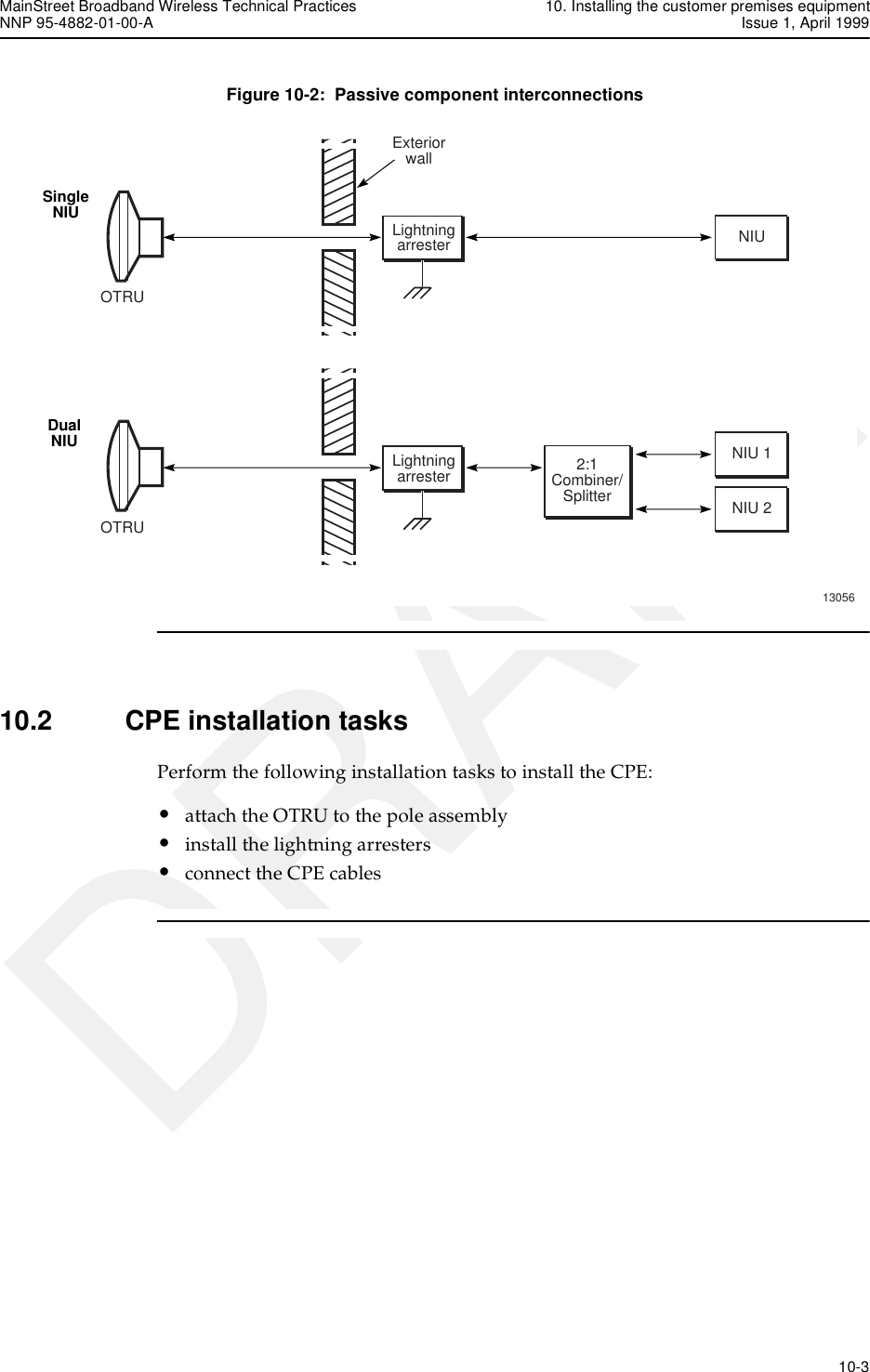
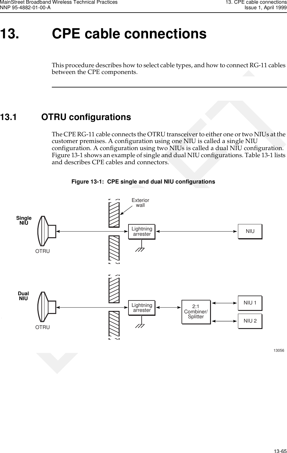
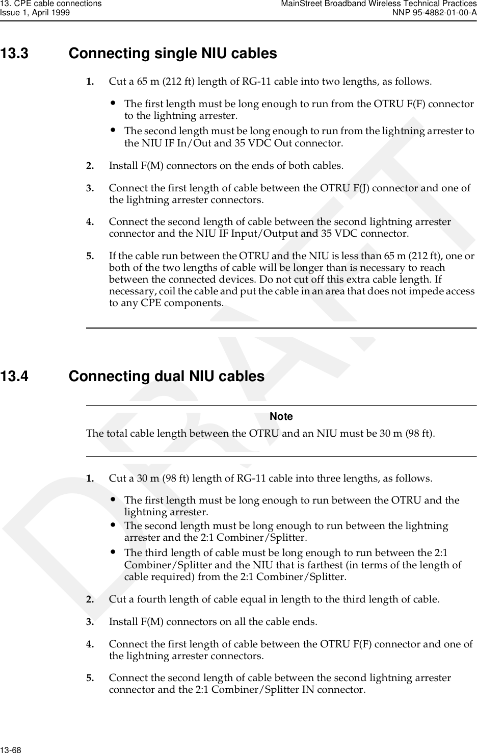
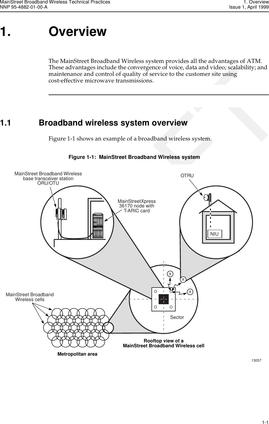
![13. CPE cable connections MainStreet Broadband Wireless Technical PracticesIssue 1, April 1999 NNP 95-4882-01-00-A13-66 DRAFTTable 13-1: CPE cables13.2 Decibel loss calculationsThe CPE cable, connectors and equipment must provide a fixed decibel loss in both the upstream and downstream directions. The downstream losses must not exceed 16 dB at 2050 MHz. The upstream losses must total 8 dB at 700 MHz, ± 1dB. If the total loss does not equal the recommended values, reduce or increase cable length accordingly.Single and dual NIU configurations require different cable lengths to achieve the desired cable loss. Figure 13-2 shows the cable lengths used in single and dual NIU configurations.Figure 13-2: Single and dual NIU cable lengthsTable 13-2 shows the loss characteristics of the single NIU components and the cable length (65 m [213 ft]) required to achieve the fixed decibel losses. NIU configuration Physical path Intermediate cables ConnectorsSingle NIU OTRU to NIU OTRU to lightning arresterLightning arrester to NIUF(M) - F(M)F(M) - F(M)Dual NIU OTRU to NIU OTRU to lightning arresterLightning arrester to 2:1 Combiner/Splitter2:1 Combiner/Splitter to each NIUF(M) - F(M)F(M) - F(M)F(M) - F(M)OTRUNIUNIU 1NIU 2LightningarresterSingle NIUDual NIU13099xyzzLightningarresterxyx + y + z = 30 mx + y = 65 m(= 213 ft)(= 98 ft)OTRU](https://usermanual.wiki/Alcatel-Canada/28T36A06A11A/User-Guide-35880-Page-86.png)
![MainStreet Broadband Wireless Technical Practices 13. CPE cable connectionsNNP 95-4882-01-00-A Issue 1, April 1999 13-67DRAFTTable 13-2: Single NIU RG-11 cable (65 m [212 ft]) decibel loss calculationsTable 13-3 shows the loss characteristics of the dual NIU components and the cable lengths required to achieve the required fixed decibel losses.Table 13-3: Dual NIU RG-11 cable (30 m [98 ft]) decibel loss calculationsSingle NIU CPE componentsMaxVSWR (x:1)Downstreamloss(2050 MHz)(dB)Upstreamloss(700 MHz)(dB)Downstreaminsertion andcoupling loss(2050 MHz)(dB)Upstreaminsertion andcoupling loss(700 MHz)(dB)DownstreamVSWR correctedtransmissionloss (2050 MHz)(dB)UpstreamVSWR correctedtransmissionloss (700 MHz)(dB)Surge protector 1.40 0.200 0.200 0.20 0.20 0.21 0.211 × RG-11 cable (65 m [212 ft])1.20 0.150 0.105 9.75 6.83 9.91 6.954 × F-type connectors 1.40 0.200 0.200 0.80 0.80 0.97 0.97Total loss — — — 10.75 7.83 11.09 8.12Dual NIU CPE components MaxVSWR (x:1)Downstreamloss(2050 MHz)(dB)Upstreamloss(700 MHz)(dB)Downstreaminsertion andcoupling loss(2050 MHz)(dB)Upstreaminsertion andcoupling loss(700 MHz)(dB)DownstreamVSWR correctedtransmissionloss (2050 MHz)(dB)UpstreamVSWR correctedtransmissionloss (700 MHz)(dB)1 × RG-11 jumper 1.20 0.150 0.105 0.00 0.00 0.00 0.001 × 2:1 Combiner/ Splitter 1.200 0.500 0.000 0.00 0.00 0.00 0.001 × surge protector 1.40 0.200 0.200 0.20 0.20 0.21 0.211 × RG-11 cable (30 m [98 ft])1.20 0.150 0.105 4.50 3.15 4.58 3.216 × F-type connectors 1.40 0.200 0.200 1.20 1.20 1.61 1.61Total loss — — — 9.05 7.66 10.75 8.64](https://usermanual.wiki/Alcatel-Canada/28T36A06A11A/User-Guide-35880-Page-87.png)