Alcatel Canada 28T36A06A11A Mainstreet Broadband Wireless System - BTS Unit User Manual 2bwireless
Alcatel Canada Inc Mainstreet Broadband Wireless System - BTS Unit 2bwireless
Draft Instruction Manual


PRINTED ON
RECYCLED PAPER
Information subject to change without notice.
Newbridge, the Newbridge logo and MainStreet are registered trademarks of Newbridge Networks Corporation.
MainStreetXpress is a trademark used by the Siemens/Newbridge alliance for comprehensive solutions in broadband
communication. No agency relationship, partnership, or joint ownership of a legal entity is to be inferred or implied by the term
alliance.
All other trademarks are the property of their respective holders.
© Copyright 1999 Newbridge Networks Corporation.
All rights reserved.
Disclaimers
Newbridge products are intended for commercial uses. Without the appropriate network design engineering, they must not be
sold, licensed or otherwise distributed for use in any hazardous environments requiring fail-safe performance, such as in the
operation of nuclear facilities, aircraft navigation or communication systems, air traffic control, direct life-support machines, or
weapons systems, in which the failure of products could lead directly to death, personal injury, or severe physical or
environmental damage. The customer hereby agrees that the use, sale, licence or other distribution of the products for any such
application without the prior written consent of Newbridge, shall be at the customer's sole risk. The customer hereby agrees to
defend and hold Newbridge harmless from any claims for loss, cost, damage, expense or liability that may arise out of or in
connection with the use, sale, licence or other distribution of the products in such applications.
This document may contain information regarding the use and installation of non-Newbridge products. Please note that this
information is provided as a courtesy to assist you. While Newbridge tries to ensure that this information accurately reflects
information provided by the supplier, please refer to the materials provided with any non-Newbridge product and contact the
supplier for confirmation. Newbridge assumes no responsibility or liability for incorrect or incomplete information provided
about non-Newbridge products.
Newbridge has made reasonable efforts to ensure that the 28110 and 28120 MainStreet NIUs, Release 1.1, comply in all material
respects with the “Referenced Detailed Functional Specification for Newbridge Product Date Compliance”. To obtain this
document and other information related to Year 2000 Date Compliance, visit the Newbridge Year 2000 Date Compliance
website at the URL:
http://www.newbridge.com/year2000/index.html
However, this does not constitute a representation or warranty. The warranties provided for Newbridge products, if any, are
set forth in contractual documentation entered into by Newbridge and its customers.

iii
Customer documentation and product support
Newbridge is committed to providing superior product documentation in
convenient and effective formats. Development and delivery of online
documentation is one way Newbridge continues to meet the changing needs of
customers.
For a wide range of documentation, see:
http://www.newbridge.com/documentation/index.html
Documentation updates
Updates to Newbridge documentation, including Technical Practices, are easily
accessible on the World Wide Web.
For documentation updates, see:
http://www.newbridge.com/updates/index.html
TechInfo.NOW
TechInfo.NOW is a subscription service that gives customers access to the latest
Newbridge information, including new applications, improved methods of
configuring and upgrading, bug fixes and product enhancements.
For each product line, TechInfo.NOW provides access to:
•Applications and Procedures
•Product Manuals
•Technical Alerts
•Product Changes and Descriptions
By providing up-to-date information, TechInfo.NOW can help customers increase
the business benefits of their Newbridge networks.
Subscribe to TechInfo.NOW at:
http://techinfo.now.newbridge.com
You can also order this service using part number 91-0030-01 TechInfo.NOW A La
Carte.

iv
Technical support
Technical Support Engineers are available to assist you 24 hours a day, 7 days a
week.
To get technical help in your region, see the chart below:
Customer feedback
We value your feedback. Please direct questions or comments about Newbridge
documentation to:
http://www.newbridge.com/documentation/feedback.html
Region Contact Number Fax Number
North and South America (703) 834-5300 (703) 318-5153
Europe, Middle East, Africa and the
former Soviet Union (Within UK) 0 1633 413 666
(Outside UK) +44 1633 413 666
Asia Pacific Australia 1 800 814 499
China 10 800 600 4602
Hong Kong 800 90 8402
Japan 00 531 60 4602
Korea 007 986 01 8280
Malaysia 1 800 88 4602
New Zealand 0 800 143600
Internet http://www.newbridge.com

MainStreet Broadband Wireless Technical Practices Table of contents
NNP 95-4882-01-00-A Issue 1, April 1999
v
DRAFT
Table of contents
Mandatory regulations
1. Overview
1.1 Broadband wireless system overview ............................................................... 1-1
1.2 Frequency and bandwidth utilization ................................................................ 1-3
2. Equipment overview
2.1 Equipment list ................................................................................................... 2-1
2.2 T-ARIC card ...................................................................................................... 2-2
Connectors .................................................................................................... 2-3
2.3 MAU .................................................................................................................. 2-4
2.4 12:2 Combiner/Splitters .................................................................................... 2-5
2.5 2:1 Combiner/Splitters ...................................................................................... 2-6
CPE 2:1 Combiner/Splitter ............................................................................ 2-6
BTS 2:1 Combiner/Splitter ............................................................................ 2-6
2.6 28110 and 28120 MainStreet CE Plus Ethernet NIUs ...................................... 2-7
Connectors .................................................................................................... 2-8
2.7 Lightning arresters ............................................................................................ 2-9
2.8 Surge protectors ............................................................................................. 2-11
2.9 OTU and ORU ................................................................................................ 2-12
Connectors .................................................................................................. 2-12
2.10 Bias-T ............................................................................................................. 2-13
2.11 OTRU .............................................................................................................. 2-14
3. Installing the base transceiver station components
3.1 BTS installation overview .................................................................................. 3-1
Siting ............................................................................................................. 3-1
Customer-supplied equipment ...................................................................... 3-1
Broadband cables ......................................................................................... 3-1
Grounded entry point .................................................................................... 3-2
OTU and ORU radios .................................................................................... 3-2
3.2 Installing BTS components ............................................................................... 3-2
3.3 BTS installation tasks ....................................................................................... 3-4
4. Installing the MAU
4.1 To install the MAU ............................................................................................ 4-1
5. Attaching an OTU or ORU to an antenna
5.1 Attaching the OTU or ORU to an antenna ........................................................ 5-1

MainStreet Broadband Wireless Technical Practices
Issue 1, April 1999 NNP 95-4882-01-00-A
vi
DRAFT
6. Installing the BTS antenna assembly
6.1 Installing the BTS mounting hardware .............................................................. 6-1
7. Installing Bias-Ts and surge protectors
7.1 Connecting the surge protector to the Bias-T ................................................... 7-1
7.2 Connecting the Bias-T to the 12:2 Combiner/Splitter ....................................... 7-2
7.3 Connecting the surge protector ground wire ..................................................... 7-2
8. Installing broadband cable lightning arresters
8.1 Connecting the mounting bracket to the BTS grounding plate ......................... 8-1
8.2 Installing the lightning arrester in the adapter bracket ...................................... 8-2
9. BTS cable connections
9.1 BTS cables ....................................................................................................... 9-1
9.2 Connecting BTS broadband cables .................................................................. 9-3
Connecting the broadband cables ................................................................ 9-9
9.3 Connecting the synchronization reference cable ............................................ 9-10
Connecting synchronization reference cables (simplex OTU/ORU) ........... 9-11
Connecting synchronization reference cables (redundant OTU/ORU) ....... 9-11
9.4 Connecting the RS-422 cables ....................................................................... 9-12
To connect a BTS RS-422 cable ................................................................ 9-12
9.5 Connecting SMA cables ................................................................................. 9-13
9.6 Connecting the Bias-T power cable ................................................................ 9-14
10. Installing the customer premises equipment
10.1 Customer premises equipment ....................................................................... 10-1
Cable loss ................................................................................................... 10-2
Passive components ................................................................................... 10-2
10.2 CPE installation tasks ..................................................................................... 10-3
11. Installing the CPE OTRU
11.1 Mounting the OTRUs ...................................................................................... 11-1
12. Installing CPE lightning arresters
12.1 Connecting the mounting bracket and lightning arrester to the
CPE grounding plate .............................................................................. 12-1
13 CPE cable connections
13.1 Decibel loss .................................................................................................... 13-1
13.2 CPE cables ..................................................................................................... 13-1
13.3 Connecting single NIU cables ......................................................................... 13-1
13.4 Connecting dual NIU cables ........................................................................... 13-2
13.5 Decibel loss calculations ................................................................................. 13-3

MainStreet Broadband Wireless Technical Practices Table of contents
NNP 95-4882-01-00-A Issue 1, April 1999
vii
DRAFT
14. OTRU alignment
14.1 Test equipment and parts ............................................................................... 14-1
14.2 Aligning the OTRU .......................................................................................... 14-2
15. Node management
15.1 Node management overview .......................................................................... 15-1
NMTI user interface .................................................................................... 15-1
To initiate a node management session with an NIU .................................. 15-1
Setting the password and level zero ........................................................... 15-3
To change the password ............................................................................. 15-3
To enable or disable level zero access ....................................................... 15-3
Screen display ............................................................................................ 15-4
15.2 Main menu ...................................................................................................... 15-5
Softkeys ...................................................................................................... 15-5
Selecting softkeys ....................................................................................... 15-6
Softkey functions ......................................................................................... 15-6
Keyboard entries ......................................................................................... 15-7
Keyboard conventions ................................................................................ 15-8
Keyboard entry formats ............................................................................... 15-8
Keyboard entry functions ............................................................................ 15-8
16. Restrictions of Release 1.1
16.1 BTS restrictions .............................................................................................. 16-1
16.2 ATM restrictions .............................................................................................. 16-2
17. Configurable features summary
17.1 NIU configurable options ................................................................................ 17-1
17.2 T-ARIC configurable options ........................................................................... 17-4
18. NIU TDM configuration options
18.1 Channel group configuration ........................................................................... 18-1
Restrictions on channel group configuration ............................................... 18-1
To add channels to a channel group ........................................................... 18-2
To assign a channel group name ................................................................ 18-2
To delete channels and channel groups ..................................................... 18-2
18.2 Port configuration ............................................................................................ 18-3
To configure CRC framing .......................................................................... 18-3
To configure DS1 build-out ......................................................................... 18-3
To configure DSX-1 line length ................................................................... 18-4
To configure the framing method ................................................................ 18-4
To configure the RAI clearing method and LOF alarm declare/clear time .. 18-4
To configure the output timing .................................................................... 18-4
To configure the port name ......................................................................... 18-5
To configure the signaling method .............................................................. 18-5
To configure the zero suppression method ................................................. 18-5
18.3 Robbed bit signaling configuration .................................................................. 18-6
To configure RBS ........................................................................................ 18-6

MainStreet Broadband Wireless Technical Practices
Issue 1, April 1999 NNP 95-4882-01-00-A
viii
DRAFT
18.4 Serial port configuration .................................................................................. 18-6
To configure the serial port baud rate ......................................................... 18-6
18.5 Trunk conditioning configuration ..................................................................... 18-7
To configure trunk conditioning ................................................................... 18-7
To configure the trunk conditioning data and signaling patterns ................. 18-8
19. ATM configuration options
19.1 NIU ATM configuration options ....................................................................... 19-1
AAL service type ......................................................................................... 19-1
To configure the AAL service type .............................................................. 19-2
Padding octet value .................................................................................... 19-2
To configure the padding octet value .......................................................... 19-2
Playout buffer .............................................................................................. 19-2
To configure the playout buffer threshold ................................................... 19-3
User data octets per cell ............................................................................. 19-3
To configure the user data octets per cell ................................................... 19-3
19.2 T-ARIC card ATM configuration options ......................................................... 19-4
NIU user data VPI ....................................................................................... 19-4
To configure the NIU user data VPI ............................................................ 19-4
20. SNMP configuration options
20.1 SNMP access communities ............................................................................ 20-1
To configure access privileges, name and IP address ............................... 20-1
To delete access communities .................................................................... 20-2
20.2 SNMP trap communities ................................................................................. 20-2
To enable or disable a trap community ....................................................... 20-2
To configure a trap community name ......................................................... 20-2
To configure an element manager IP address ............................................ 20-2
To delete trap communities ......................................................................... 20-3
21. Air interface configuration
21.1 Air interface-related parameters ..................................................................... 21-1
21.2 Frequency offsets ........................................................................................... 21-3
Downstream frequency offset ..................................................................... 21-3
Rx LO offset ................................................................................................ 21-3
21.3 Frequency utilization ....................................................................................... 21-4
Channel bandwidth, frequency and number of channels ............................ 21-6
Downstream channel frequency and bandwidth ......................................... 21-6
Downstream IF start frequency ................................................................... 21-6
Rx upstream frequency start and end ......................................................... 21-6
Tx downstream frequency start and end ..................................................... 21-7
Upstream channel frequency ...................................................................... 21-7
Upstream IF start frequency ....................................................................... 21-7
Upstream frequency offset .......................................................................... 21-7
21.4 Groups ............................................................................................................ 21-8
21.5 NIU .................................................................................................................. 21-8
Add NIU ...................................................................................................... 21-8
NIU ID and NIU serial number .................................................................... 21-8
NIU type ...................................................................................................... 21-8

MainStreet Broadband Wireless Technical Practices Table of contents
NNP 95-4882-01-00-A Issue 1, April 1999
ix
DRAFT
21.6 Power level ..................................................................................................... 21-9
NIU power level functions ........................................................................... 21-9
21.7 Rx and Tx redundancy .................................................................................. 21-10
21.8 Slot parameters ............................................................................................ 21-11
Card type .................................................................................................. 21-11
Slot name .................................................................................................. 21-11
21.9 Upstream timeslot utilization ......................................................................... 21-12
Contention timeslots ................................................................................. 21-12
21-12
Guard and polling timeslots ...................................................................... 21-13
Reserved DBA timeslots ........................................................................... 21-13
21.10 NIU configuration .......................................................................................... 21-14
To add frequencies ................................................................................... 21-14
To delete channels .................................................................................... 21-15
To configure the maximum power level after network entry ..................... 21-15
To configure the maximum power level before network entry .................. 21-15
To configure the minimum power level before network entry ................... 21-15
To configure the minimum power level after network entry ...................... 21-16
To configure the Tx LO and Rx LO frequency offsets ............................... 21-16
To configure the RF band start and end frequency and IF band start frequency
21-16
21.11 T-ARIC group configuration .......................................................................... 21-16
To add or remove a T-ARIC card to or from a T-ARIC group ................... 21-17
To configure the downstream IF start frequency ...................................... 21-17
To configure Rx and Tx control ................................................................. 21-17
To configure the Rx upstream start and end frequency ............................ 21-18
To configure the Tx downstream start and end frequency ........................ 21-18
To configure the upstream IF start frequency ........................................... 21-18
To configure the upstream frequency offset ............................................. 21-19
21.12 Downstream T-ARIC modem configuration .................................................. 21-19
To configure the downstream channel frequency ..................................... 21-19
To configure the downstream channel width ............................................ 21-19
To configure the Tx default power level .................................................... 21-20
21.13 Upstream T-ARIC modem configuration ....................................................... 21-20
To add or remove an NIU ......................................................................... 21-20
To configure the number of contention timeslots ...................................... 21-21
To configure the demodulator operational status ...................................... 21-21
To configure the number of guard timeslots ............................................. 21-22
To configure the number of polling timeslots ............................................ 21-22
To configure the number of reserved DBA timeslots ................................ 21-23
To configure the upstream channel frequency .......................................... 21-24
21.14 T-ARIC card NIU configuration ..................................................................... 21-24
To configure the NIU serial number .......................................................... 21-24
To configure the NIU type ......................................................................... 21-25
21.15 T-ARIC card port configuration ..................................................................... 21-25
To configure the T-ARIC card port name .................................................. 21-25
21.16 T-ARIC card slot configuration ...................................................................... 21-25
To configure the T-ARIC card type ........................................................... 21-25
To configure the T-ARIC card slot name .................................................. 21-26

MainStreet Broadband Wireless Technical Practices
Issue 1, April 1999 NNP 95-4882-01-00-A
x
DRAFT
22. Status information
22.1 Status information ........................................................................................... 22-1
To view NIU T1 or E1 port status ................................................................ 22-2
To view base network, NIU modem and housekeeping link status ............. 22-2
To view NIU status ...................................................................................... 22-2
To view T-ARIC card port status ................................................................. 22-2
To view T-ARIC card slot status ................................................................. 22-3
23. T-ARIC card statistics
23.1 Statistics ......................................................................................................... 23-1
To view ATM endpoint statistics ................................................................. 23-2
To view T-ARIC card port statistics ............................................................. 23-2
To refresh statistics ..................................................................................... 23-2
24. NIU statistics
24.1 NIU port AAL1 statistics .................................................................................. 24-1
To view NIU port AAL1 statistics ................................................................. 24-2
To view NIU channel group AAL1 statistics ................................................ 24-3
24.2 T1 and E1 statistics ........................................................................................ 24-3
To view NIU T1 port statistics ..................................................................... 24-7
To view NIU E1 port G.821 statistics .......................................................... 24-7
To view NIU E1 port line error statistics ...................................................... 24-8
To refresh statistics ..................................................................................... 24-8
25. LED activity
25.1 LED activity ..................................................................................................... 25-1
NIU LED activity .......................................................................................... 25-1
T-ARIC card LED activity ............................................................................ 25-2
26. Loopbacks
26.1 T-ARIC card loopbacks ................................................................................... 26-1
To configure the T-ARIC card port reference point ..................................... 26-1
To configure the OAM segment type .......................................................... 26-2
To initiate an OAM loopback ....................................................................... 26-2
26.2 28110 and 28120 MainStreet NIU loopbacks ................................................. 26-3
To initiate, clear or reset an NIU loopback .................................................. 26-3
27. Alarms
27.1 Alarm descriptions .......................................................................................... 27-1
To acknowledge alarms .................................................................................. 27-3
To acknowledge alarms .............................................................................. 27-3
To clear alarms ........................................................................................... 27-3
To configure remote alarm logging over CPSS .......................................... 27-4
To configure remote alarm logging over SNMP .......................................... 27-4
To configure the alarm queue overflow method .......................................... 27-4
To configure the remote alarm queue overflow method ............................. 27-5
To delete alarms ......................................................................................... 27-5

MainStreet Broadband Wireless Technical Practices Table of contents
NNP 95-4882-01-00-A Issue 1, April 1999
xi
DRAFT
To filter the alarm display ............................................................................ 27-6
To view alarms in a specific queue ............................................................. 27-6
To view an alarm summary ......................................................................... 27-7
28. Resetting the T-ARIC cards and NIUs
28.1 Resetting a T-ARIC card or port ..................................................................... 28-1
To reset the T-ARIC card ............................................................................ 28-1
To reset the T-ARIC card port ..................................................................... 28-1
28.2 Resetting the NIU or NIU modem ................................................................... 28-1
To reset the NIU .......................................................................................... 28-1
To reset the NIU modem ............................................................................. 28-2
Glossary
Index


MainStreet Broadband Wireless Technical Practices Mandatory Regulations
NNP 95-4882-01-00-A Issue 1, April 1999
xiii
DRAFT
Mandatory regulations
This chapter outlines the mandatory regulations for the installation and operation of
the MainStreet Broadband Wireless system. Adherence to these regulations is
necessary to comply with regulatory requirements.
General requirements
The sections that follow outline the mandatory regulations governing the
installation and operation of the MainStreet Broadband Wireless system. Adherence
to these instructions is necessary to make sure regulatory compliance requirements
are met.
Warning
The MainStreet Broadband Wireless system T-ARIC cards, 28110 and 28120
MainStreet CE Plus Ethernet NIUs, OTRUs, OTUs and ORUs contain no
user-serviceable parts. Contact Newbridge for repair and servicing.
Caution
To prevent accidental electrical shorting of cards or modules, the cards or modules
must be correctly aligned between the card guides before insertion.
Local regulations
All BTS and CPE installations must meet all local, national and civil electrical/safety
regulations of the area where they are installed.
Wireless safety compliance in the United States of America
It is the responsibility of the wireless licence holder to ensure that the requirements
of OET Bulletin 65 are met in the USA.
Wireless safety compliance in Canada
It is the responsibility of the wireless licence holder to ensure that the requirements
of Safety Code 6 are met in Canada.

Mandatory Regulations MainStreet Broadband Wireless Technical Practices
Issue 1, April 1999 NNP 95-4882-01-00-A
xiv
DRAFT
Placement of transmitting equipment
To prevent exposure to non-ionizing radiation, the OTU and OTRU should always
be mounted to a minimum of 3 m (10 ft) above ground level or roof-top level. If in
the case of a wall-mount OTRU, the unit should be mounted three meters away from
any point of exposure such as windows, balconies or doors.
OTU and OTRU service and repair safety precautions
Only authorized personnel should service OTU and OTRU units.
Danger
Never touch the OTU or OTRU antennas while they are in operation. Do not stand
in front of OTU and OTRU antennas, and never pass closer than 1 m from the front
of an operating OTU or OTRU.
The OTU and OTRU should be deactivated prior to being installed or serviced.
Service and repair preparation activities should be made as close to the base of an
elevated OTU or OTRU as possible, as the risk of exposure to non-ionizing radiation
increases as you move further from the base toward the area that is serviced by the
transmitter.
Equipment interconnection points
All card faceplate connectors are SELV.
Connect SELV circuits on this equipment only to other circuits that comply with the
requirements of SELV circuits as defined in IEC 60950.
External power supply
The dc source for the wireless antenna must meet the requirements of a SELV source
in accordance with IEC 60950 based standards and limit the output to 100VA.
Warning 1
BTS equipment is intended for use when powered by an appropriate external -48 V
power supply or rack mount shelf approved by Newbridge. The use of any other
power supply may invalidate regulatory approvals of this unit.
Warning 2
The 0VR connector on the -48 V power supply that supplies power to the OTU and
ORU must be grounded to the same ground used by the MainStreetXpress 36170
system that connects to the BTS equipment.

MainStreet Broadband Wireless Technical Practices Mandatory Regulations
NNP 95-4882-01-00-A Issue 1, April 1999
xv
DRAFT
Prevention of access to the user
Only authorized personnel should have access to the equipment. Install the
equipment in a restricted-access location or similar environment, and post
appropriate warning signs to indicate safety concerns. Failure to prevent
unauthorized user access will invalidate any approvals given to this equipment.
Regulatory symbols
The following sections show examples of regulatory approval symbols generally
used. They may be used on product markings such as approval labels. These
symbols are described in IEC 417.
Power on
This symbol indicates the on position of the main on/off switch.
Figure 1: On position symbol for on/off switch
Power off
This symbol indicates the off (O) position of the main on/off switch.
Figure 2: Off position symbol for on/off switch
Protective grounding terminal
These symbols indicate a terminal that must be connected to earth ground prior to
making any other connections to the equipment.
Figure 3: Supply wire protective earth
9715
9716
9717

Mandatory Regulations MainStreet Broadband Wireless Technical Practices
Issue 1, April 1999 NNP 95-4882-01-00-A
xvi
DRAFT
Figure 4: Protective earth
Dangerous voltage
The lightning flash with an arrowhead symbol, within an equilateral triangle,
indicates the presence of uninsulated “dangerous voltage” within the product's
enclosure that could cause electric shock. Labels bearing this symbol are installed on
the outside of the product enclosure.
Figure 5: Dangerous voltage symbol
Instructions
The exclamation point within a triangle indicates the existence of important
operating and maintenance (servicing) instructions in the product documentation.
Figure 6: Important instructions symbol
Elevated non-ionizing radiation levels
This symbol identifies equipment that emits elevated levels of non-ionizing
radiation. Do not approach equipment that is marked with this symbol unless power
to the device is disconnected. Labels bearing this symbol are installed on the outside
casing of transmitter devices.
Figure 7: Elevated non-ionizing radiation levels symbol
9718
9719
9720
13111

MainStreet Broadband Wireless Technical Practices Mandatory Regulations
NNP 95-4882-01-00-A Issue 1, April 1999
xvii
DRAFT
International EMC compliance
The EMC compliance of these products relies on following the installation processes
correctly.
Failure to follow the correct installation processes may result in a non-compliance to
the EMC standards against which these products have been assessed.
28110 and 28120 CE Plus Ethernet NIU EMC compliance
This Class B digital apparatus complies with Canadian ICES-003. Cet appareil
numérique de la classe B est conforme à la norme NMB-003 du Canada.
T-ARIC card EMC compliance
This Class A digital apparatus complies with Canadian ICES-003. Cet appareil
numérique de la classe A est conforme à la norme NMB-003 du Canada.
Industry Canada regulations
The Industry Canada (formerly known as the Department of Communications) label
identifies certified equipment. This certification means that the equipment meets
certain telecommunications network protective, operational and safety
requirements as prescribed in the Terminal Equipment Technical Requirements
document(s). Industry Canada does not guarantee that the equipment will operate
to the user's satisfaction.
Before installing this equipment, get permission to connect to the facilities of the
local telecommunications company. Install the equipment using an acceptable
method of connection. Compliance with the above conditions may not prevent
degradation of service in some situations.
The standard connecting arrangement codes for the MainStreet Broadband Wireless
system are CA11A, CA21A, CA48C, CA81A, CA2EA, CA2FA, CA2GA, CA2HA and
CA-A11.
In some cases, the company's inside wiring for single-line individual service may be
extended by means of a certified telephone extension cord. Compliance with these
conditions may not prevent degradation of service in some situations.
Repairs to certified equipment must be made by an authorized Canadian
maintenance facility designated by the supplier. If the user repairs or alters this
equipment, or if the equipment malfunctions, the telecommunications company
may request that the equipment be disconnected.
Make sure that the electrical ground connections of the power utility, telephone lines
and internal metallic water pipe system, if present, are connected together. This
precaution is especially important in rural areas.

Mandatory Regulations MainStreet Broadband Wireless Technical Practices
Issue 1, April 1999 NNP 95-4882-01-00-A
xviii
DRAFT
Caution
Do not attempt to make electrical ground connections. Contact the electrical
inspection authority or an electrician.
Safety approval for dc systems
The dc source for the MainStreet Broadband Wireless system must meet the
requirements of a SELV source in accordance with CSA C22.2 No. 950. These
systems are intended for use with a SELV secondary source that is electrically
isolated from the ac source and that is reliably connected to earth.
MainStreet Broadband Wireless Technical Practices 1. Overview
NNP 95-4882-01-00-A Issue 1, April 1999
1-1
DRAFT
1. Overview
The MainStreet Broadband Wireless system provides all the advantages of ATM.
These advantages include the convergence of voice, data and video; scalability; and
maintenance and control of quality of service to the customer site using
cost-effective microwave transmissions.
1.1 Broadband wireless system overview
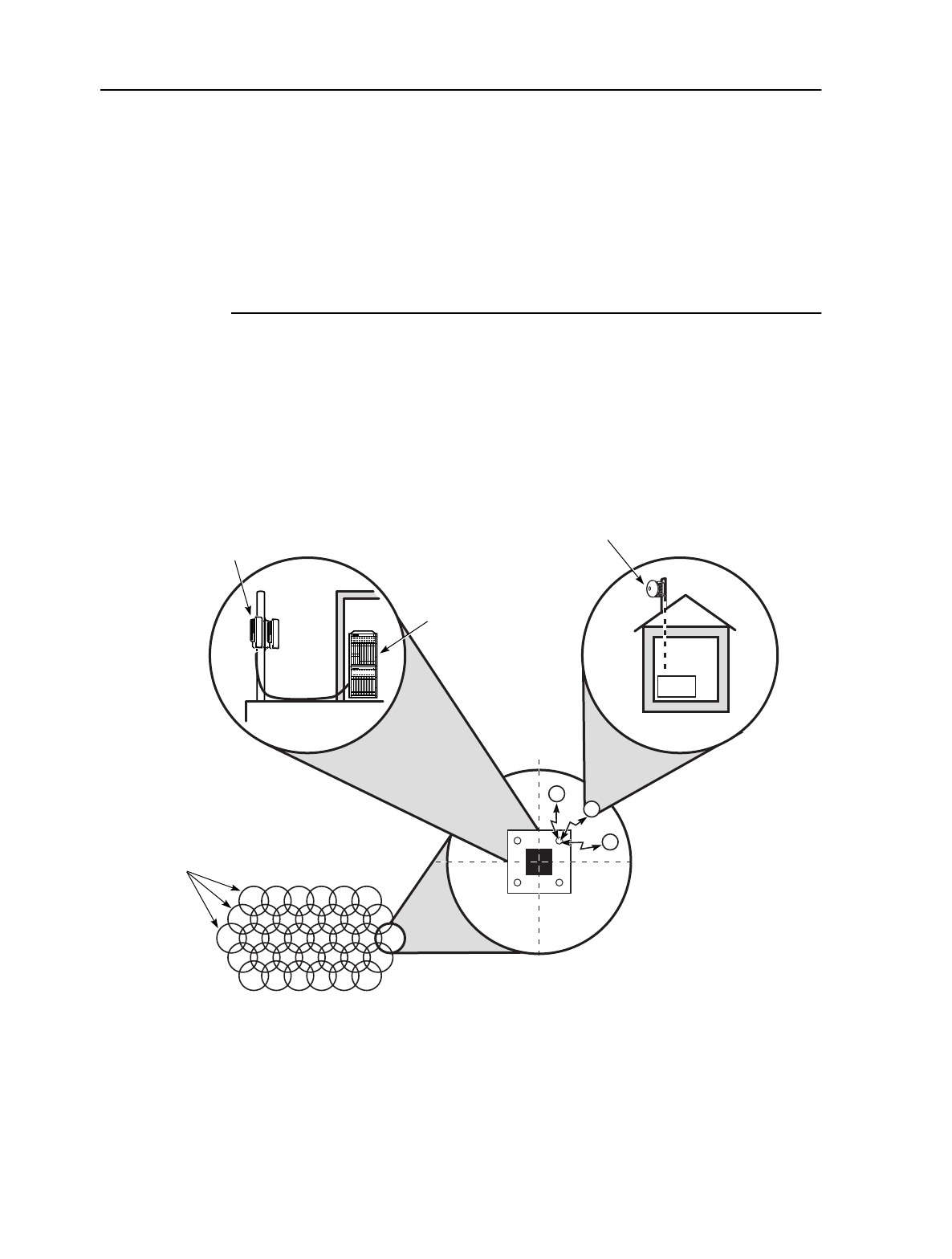
Figure 1-1 shows an example of a broadband wireless system.
Figure 1-1: MainStreet Broadband Wireless system
13057
MainStreet Broadband
Wireless cells
Sector
MainStreetXpress
36170 node with
T-ARIC card
MainStreet Broadband Wireless
base transceiver station
ORU/OTU
x
x
NIU
OTRU
x
Metropolitan area
Rooftop view of a
MainStreet Broadband Wireless cell

1. Overview MainStreet Broadband Wireless Technical Practices
Issue 1, April 1999 NNP 95-4882-01-00-A
1-2
DRAFT
Table 1-1 describes major components of a broadband wireless system.
Table 1-1: Components of the wireless system
Most of the air interface configuration is performed through the T-ARIC card;
configuration of the NIUs is primarily related to TDM functionality. ATM
functionality is provided by other cards in the MainStreetXpress 36170 shelf.
Table 1-2 describes the network management support available for the MainStreet
Broadband Wireless system.
Table 1-2: MainStreet Broadband Wireless network management
Term Description
ATM backbone The ATM backbone system is used for switching intercell traffic and connecting
multiple BTSs.
BTS The Base Transceiver Station is the linking point between customers in the
coverage area of the BTS and the backbone network. The BTS is a hub that
collects and delivers all traffic to and from subscribers within the coverage area.
Cell The cell is the geographical area that is within range of the transmit and receive
antennas at the BTS.
NIU The Network Interface Unit provides the linking point between the customer
equipment and the air interface at the customer site. The MainStreet Broadband
Wireless system includes the 28110 and 28120 MainStreet CE Plus Ethernet
NIUs.
OTU The OTU is the transmit radio for the BTS.
ORU The ORU is the receive radio for the BTS.
Sector A sector is the smallest geographical area which has access to the entire Tx and
Rx RF spectrum used in a wireless system. A sector can be a division of a cell,
or an entire cell. A cell is often divided into sectors to simplify network and node
management, and to take advantage of antenna profiles.
T-ARIC card The Time Division Multiple Access - ATM Radio Interface Card resides in a
MainStreetXpress 36170 shelf, and provides a cell relay modem interface
between the BTS and one or more NIUs.
T-ARIC group A T-ARIC group is two or more T-ARIC cards configured to use the same
OTU/ORU. This allows for an increase in CPE density within the cell.
OTRU An OTRU is a transceiver installed at a CPE site that connects to an NIU,
providing RF connectivity between the NIU and the OTU/ORU.
Term Description
MainStreetXpress
45020 The MainStreetXpress 45020 Element Manager provides remote SNMP
management of the NIUs.
MainStreetXpress
46020 The MainStreetXpress 46020 Network Manager provides remote management
of the T-ARIC cards.
NMTI The NMTI is a user interface for local management of the T-ARICs and NIUs.
Remote access is configured through the PSTN.
MainStreet Broadband Wireless Technical Practices 1. Overview
NNP 95-4882-01-00-A Issue 1, April 1999
1-3
DRAFT
1.2 Frequency and bandwidth utilization
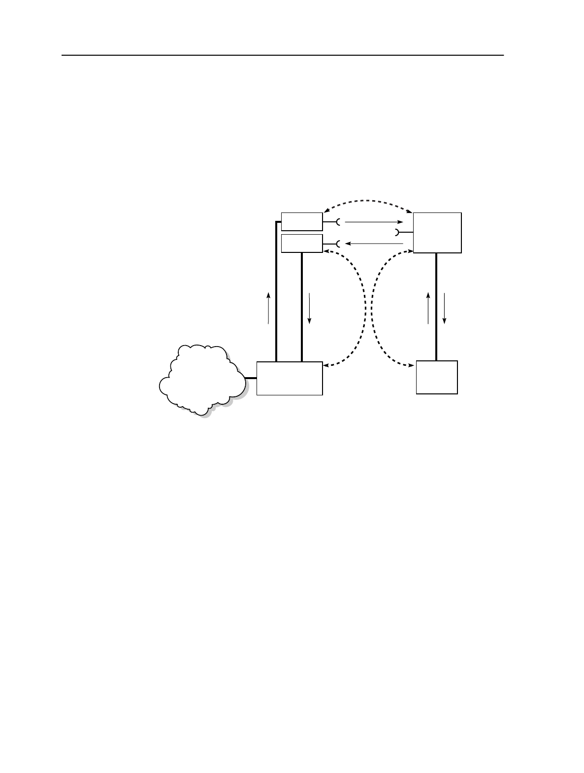
Figure 1-2 shows the signal flow between the T-ARIC card located at the BTS and an
NIU located at a CPE site. The signals between the T-ARIC card and the OTU/ORU
use IF. Signals between the OTU, ORU and the OTRU transceiver use RF. Signals
between the OTRU transceiver and the NIU also use IF.
Figure 1-2: Signal flow
The term downstream always refers to the communication flow from the T-ARIC
card to the NIU. Upstream always refers to communication flow from the NIU to the
T-ARIC card.
The MainStreet Broadband Wireless system supports wireless communications in
the 20 to 40 GHz frequency range. The actual frequencies used are
country-dependent.
Bandwidth between the T-ARIC card and the OTU and ORU is in the IF range. The
range is 400 to 900 MHz upstream, and 950 to 2050 MHz downstream. Bandwidth
between the NIU and the transceiver is also in the IF range. The relationship between
IF and RF frequencies is determined by the specific radios that are used in the OTU
and ORU and the transceiver.
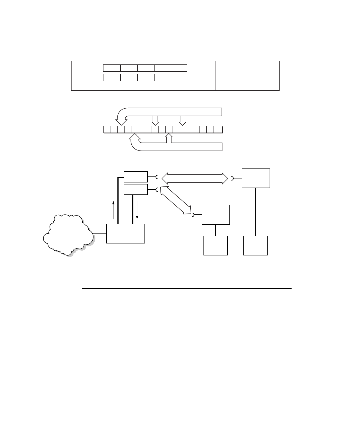
Figure 1-3 shows details of data flow on an upstream and a downstream channel.
The downstream channel is broadcast to all NIUs configured to be in the same
T-ARIC group as the broadcasting T-ARIC card.
The MainStreet Broadband Wireless system uses TDMA to allow multiple NIUs to
use a single upstream channel. In Figure 1-3, two NIUs are broadcasting on a single
channel. The channel is divided into timeslots. These timeslots are allocated to the
NIUs by system resources, not by manual configuration. The number of timeslots
allocated to an NIU depends on the configured TDM traffic.
T-ARIC
ATM network
(through
MainStreetXpress
36170)
BTS CPE
OTU
ORU
Tx
Rx
Downstream DownstreamUpstream Upstream
Upstream
Downstream
RF
OTRU
IF
NIU
11437
1. Overview MainStreet Broadband Wireless Technical Practices
Issue 1, April 1999 NNP 95-4882-01-00-A
1-4
DRAFT
Figure 1-3: Upstream and downstream channels
13073
ATM network
(through
MainStreetXpress
36170)
OTRU
Single NIU
Dual NIU
OTRU
Dual
NIU
Upstream channel
accommodates multiple
NIUs on a single 9-MHz channel
012 132
Timeslots
Upstream
channel
Downstream
channel
Timeslot allocation
handled by system
resources
T-ARIC
Downstream Upstream
OTU
ORU
Tx
Rx
Downstream bandwidth
18 MHz (273 ATM cells)
36 MHz (553 ATM cells)
Packet n
Packet n+1
MPEG -2 (7 ATM cells per 2-packet sequence)
CTL 5 6 74 (b)
CTL 2 3 4 (a)1
Single
NIU

MainStreet Broadband Wireless Technical Practices 2. Equipment overview
NNP 95-4882-01-00-A Issue 1, April 1999
2-1
DRAFT
2. Equipment overview
This chapter describes the physical components of the MainStreet Broadband
Wireless system.
2.1 Equipment list
Tables 2-1 and 2-2 list the physical components and part numbers of the MainStreet
Broadband Wireless system. These tables do not include the MainStreetXpress 36170
shelves, power supplies and cables.
Table 2-1: BTS equipment list
Name Part number
12:2 Combiner/Splitter 90-6659-01
2:1 Combiner/Splitter 90-6734-01
Lightning arrester 90-6517-01
OTU 90-4568-02/05
ORU 90-4567-02/05
Antennas 90-4563-02/05 (horizontal polarization)
90-4564-02/05 (vertical polarization)
RS-422 lightning arrester 90-6519-01
Surge protector 90-6739-01
Bias-T 90-6516-01
Bias-T power cable 90-6518-01
MAU 90-6474-01
T-ARIC card 90-6206-01

2. Equipment overview MainStreet Broadband Wireless Technical Practices
Issue 1, April 1999 NNP 95-4882-01-00-A
2-2
DRAFT
Table 2-2: CPE equipment list
2.2 T-ARIC card
The T-ARIC card is a double-width card that is installed in any two adjacent slots of
the MainStreetXpress 36170 Peripheral Shelf. The T-ARIC card provides a cell relay
modem interface from the BTS to the NIUs.
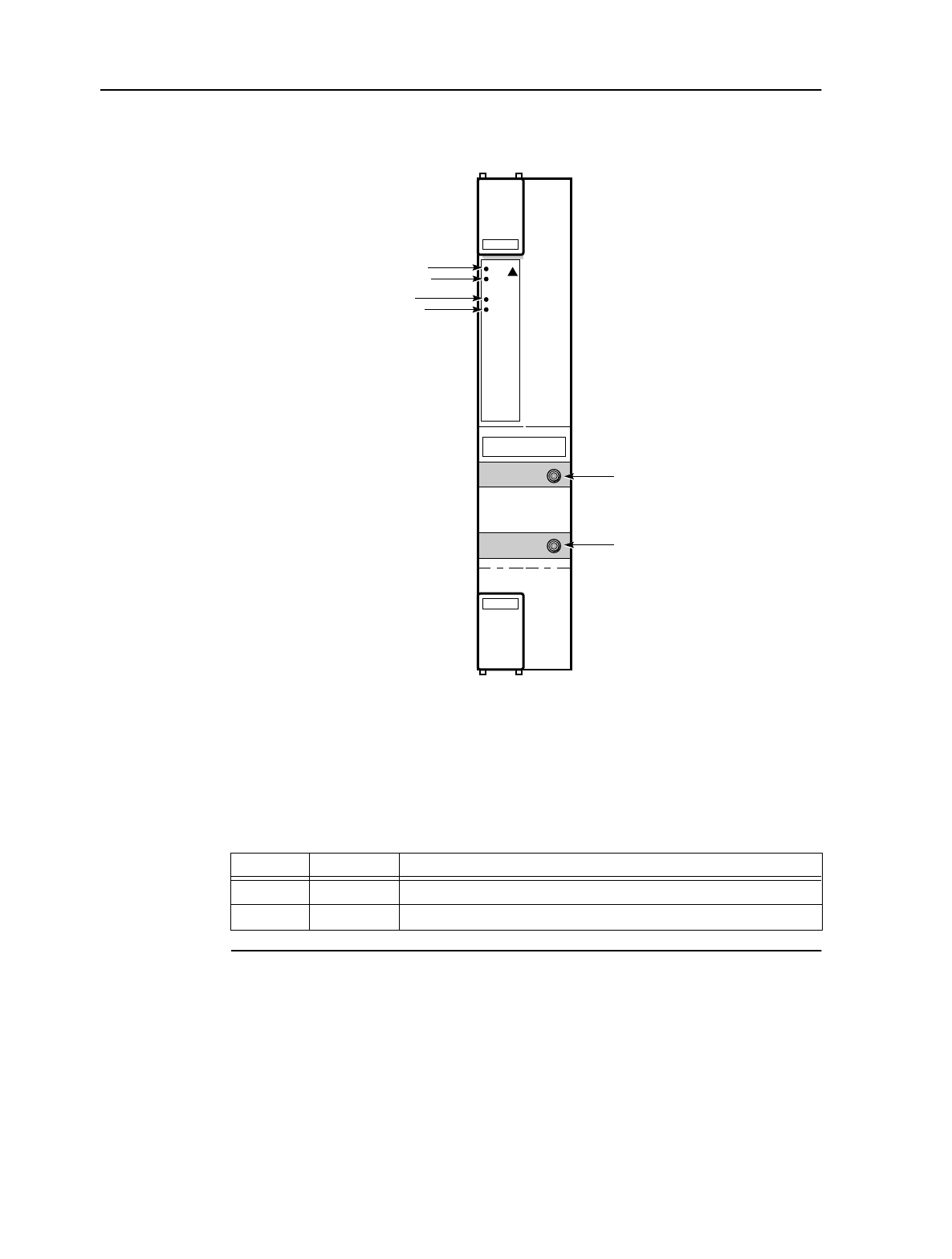
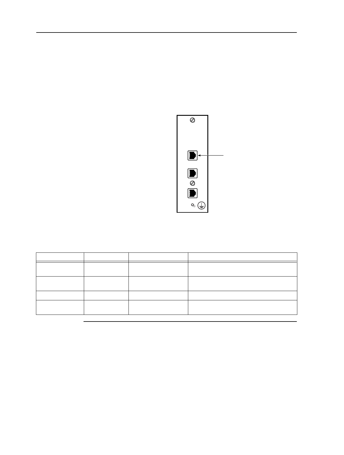
Figure 2-1 shows the T-ARIC card faceplate. The following four LEDs can be seen on
the T-ARIC card faceplate. Refer to chapter 25 for information about LED activity.
•Status
•Activity
•Link
•Alarm
Name Part number
2:1 Combiner/Splitter 90-6524-01
28110 MainStreet T1 CE Plus Ethernet NIU 90-6210-01 (120 V)
90-6210-02 (240 V)
28120 MainStreet E1 CE Plus Ethernet NIU 90-6210-04 (120 Ω)
Lightning arrester 90-6522-01
OTRU 90-6626
MainStreet Broadband Wireless Technical Practices 2. Equipment overview
NNP 95-4882-01-00-A Issue 1, April 1999
2-3
DRAFT
Figure 2-1: T-ARIC card faceplate
Connectors
Table 2-3 describes the T-ARIC card faceplate connectors.
Table 2-3: T-ARIC card faceplate connectors
T-ARIC
Active
Signal
Status
Activity
Link
Alarm
Status
11310
Tx
Rx
Activity
Status
Alarm
Link
Tx connector
Rx connector
Name Type Purpose
Rx SMA(F) Carries Rx signal from ORU to the T-ARIC card
Tx SMA(F) Carries Tx signal from T-ARIC card to OTU
2. Equipment overview MainStreet Broadband Wireless Technical Practices
Issue 1, April 1999 NNP 95-4882-01-00-A
2-4
DRAFT
2.3 MAU
The MAU is used to connect RS-422 cables between the T-ARIC card and the OTU
and ORU. The MAU installs on the backplane behind each T-ARIC card. Figure 2-2
shows the front of the MAU and the location of the MAU connectors. Table 2-4
describes the MAU connectors.
Figure 2-2: Front view of MAU
Table 2-4: MAU connectors
ORU
OTU
13000
AMM
Name Type Location Purpose
ORU RS-422 Front of MAU Connects to the ORU RS-422 connector via
intermediate cabling and lightning arresters
OTU RS-422 Front of MAU Connects to the OTU RS-422 connector via
intermediate cabling and lightning arresters
MAU interface DSUB Back of MAU Connects to the T-ARIC card DSUB connector
AMM RS-232 Front of MAU Used for software downloading to the AMM by
Newbridge personnel
MainStreet Broadband Wireless Technical Practices 2. Equipment overview
NNP 95-4882-01-00-A Issue 1, April 1999
2-5
DRAFT
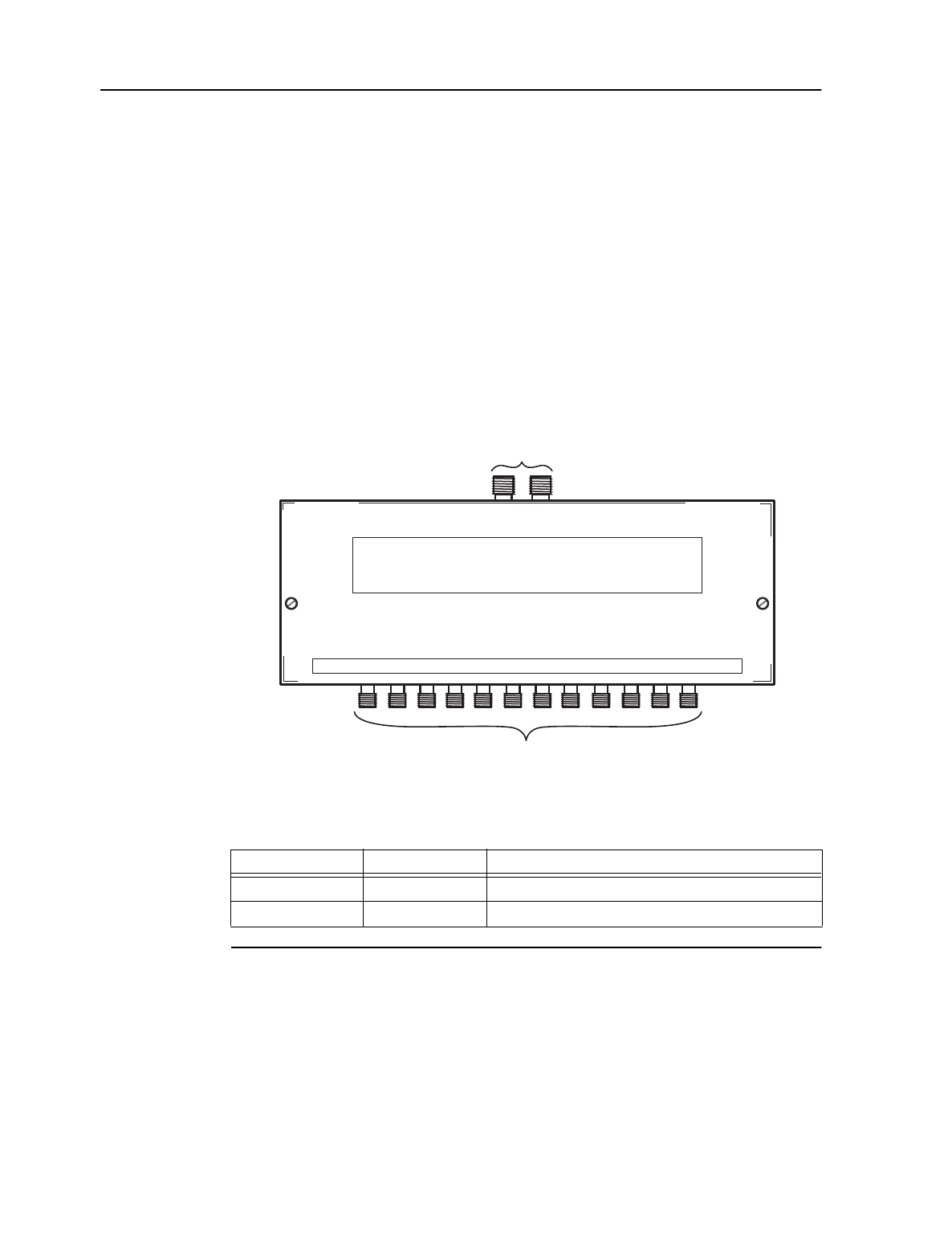
2.4 12:2 Combiner/Splitters
12:2 Combiner/Splitters connect up to 12 T-ARIC cards to the OTU and ORU. A
typical application uses one 12:2 Combiner/Splitter to connect T-ARIC cards to the
OTU, and one Combiner/Splitter to connect T-ARIC cards to the ORU.
The OTU 12:2 Combiner/Splitter combines outgoing Tx signals from each T-ARIC
card into a single Tx signal to the connected OTU.
The ORU 12:2 Combiner/Splitter splits the incoming ORU Rx signals into separate
Rx signals for each T-ARIC card.
Figure 2-3 shows the 12:2 Combiner/Splitter. Table 2-5 lists and describes the
connectors.
Figure 2-3: 12:2 Combiner/Splitter
Table 2-5: BTS 12:1 Combiner/Splitter connectors
Name Type Purpose
T-ARIC connectors SMA(F) Connect to T-ARIC card through SMA cables
Bias-T connectors F(F) Connect to Bias-Ts
12687
To T-ARIC cards
To Bias-Ts
2. Equipment overview MainStreet Broadband Wireless Technical Practices
Issue 1, April 1999 NNP 95-4882-01-00-A
2-6
DRAFT
2.5 2:1 Combiner/Splitters
There are two types of 2:1 Combiner/Splitters used in the MainStreet Broadband
Wireless system:
•CPE 2:1 Combiner/Splitter
•BTS 2:1 Combiner/Splitter
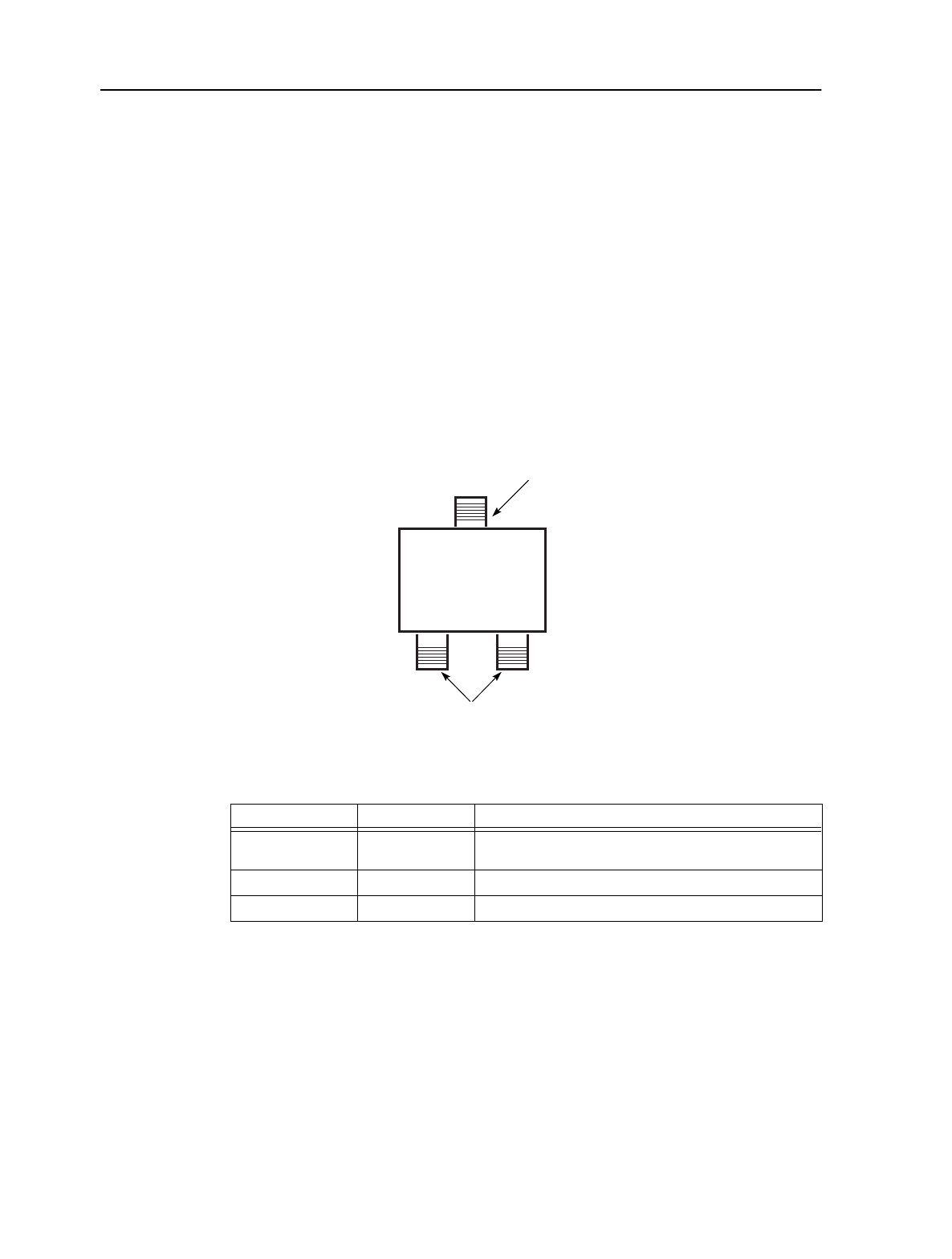
CPE 2:1 Combiner/Splitter
The CPE 2:1 Combiner/Splitter is used to connect two NIUs to a single OTRU in a
dual NIU CPE configuration. Figure 2-4 shows a CPE 2:1 Combiner/Splitter. Table
2-6 lists and describes the connectors.
Figure 2-4: CPE 2:1 Combiner/Splitter
Table 2-6: CPE 2:1 Combiner/Splitter connectors
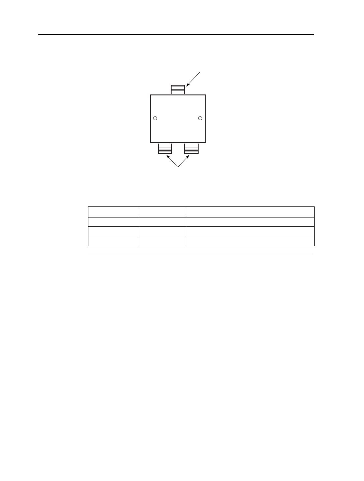
BTS 2:1 Combiner/Splitter
The BTS 2:1 Combiner/Splitter is used to connect the synchronization reference
cable to OTUs and ORUs in an OTU/ORU redundant configuration. Figure 2-5
shows a BTS 2:1 Combiner/Splitter. Table 2-7 lists and describes the connectors.
13098
F(F) connector
IN
OUT DC BLK
OUT
F(F) connectors
Name Type Purpose
IN F(F) Connects to the OTRU via intermediate cabling and
lightning arresters
OUT F(F) Connects to one of two NIUs
DC BLK OUT F(F) Connects to one of two NIUs
MainStreet Broadband Wireless Technical Practices 2. Equipment overview
NNP 95-4882-01-00-A Issue 1, April 1999
2-7
DRAFT
Figure 2-5: BTS 2:1 Combiner/Splitter
Table 2-7: BTS 2:1 Combiner/Splitter connectors
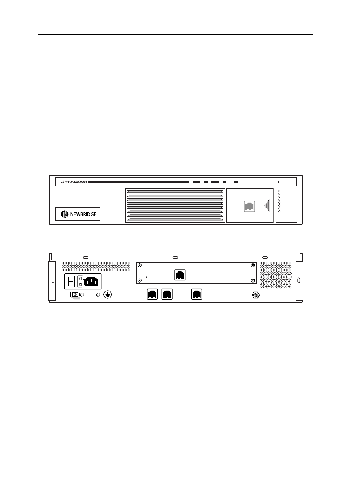
2.6 28110 and 28120 MainStreet CE Plus Ethernet NIUs
The 28110 MainStreet CE Plus Ethernet T1 NIU provides a single T1 interface and a
single Ethernet interface. The 28120 MainStreet CE Plus Ethernet E1 NIU provides a
single E1 interface and a single Ethernet interface.
NIUs have an internal Modem module that is similar to the one used in the T-ARIC
card. The Modem module converts a digital ATM signal to an analog IF signal for
transmission, and conversely, converts a received analog IF signal to a digital ATM
signal.
Figure 2-6 shows the faceplate and back panel of a 28110 MainStreet CE Plus
Ethernet T1 NIU. The 28120 MainStreet CE Plus Ethernet E1 NIU has similar panels.
13120
N(F) connector
N(F) connectors
1
23
Name Type Purpose
1 N(F) Connects to the synchronization reference cable
2 N(F) Connects to an OTU/ORU 100 MHz reference connector
3 N(F) Connects to an OTU/ORU 100 MHz reference connector
2. Equipment overview MainStreet Broadband Wireless Technical Practices
Issue 1, April 1999 NNP 95-4882-01-00-A
2-8
DRAFT
The following eight LEDs can be seen on a 28110 or 28120 MainStreet NIU faceplate.
Refer to chapter 25 for information about LED activity.
•Status
•Network Connect
•Tx Data
•Rx Data
•T1/E1 Signal
•T1/E1 Alarm
•Ethernet Link
•Ethernet Activity
Figure 2-6: 28110 MainStreet T1 NIU
Connectors
Table 2-8 describes the 28110 and 28120 MainStreet NIU connectors.
T1 Circuit Emulation + Ethernet Network Interface Unit
Power
Status
Network Connect
Tx Data
Rx Data
T1/E1 Alarm
T1/E1 Signal
Ethernet Link
Ethernet Activity
Front
Back
13003
O
I
IF In/Out
35 VDC Out
Ethernet 1
NVM scrub
Ethernet 2 Serial 2
Serial 1
T1/E1

MainStreet Broadband Wireless Technical Practices 2. Equipment overview
NNP 95-4882-01-00-A Issue 1, April 1999
2-9
DRAFT
Table 2-8: NIU connectors
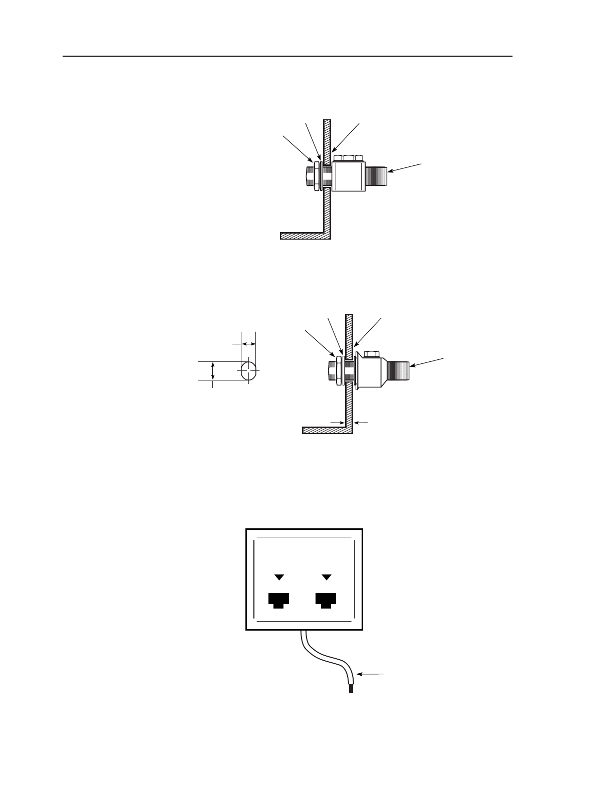
2.7 Lightning arresters
Lightning arresters provide protection against lightning strikes to an OTRU, OTU or
ORU. Each lightning arrester contains a gas discharge tube that shunts
equipment-damaging lightning to ground. The gas discharge tubes should be
replaced on a regular basis as recommended by the manufacturer.
The MainStreet Broadband Wireless system uses three types of lightning arresters:
•Type F (used at the CPE)
•Type N (used at the BTS)
•RS-422 (used at BTS)
Lightning arresters connect to ground either by a direct connection to a bulkhead, or
by mounting brackets. It is recommended to ground lightning arresters through
mounting brackets that are connected to a copper plate bolted to a grounded entry
point.
Figure 2-7 shows a Type F lightning arrester installed in a mounting bracket.
Figure 2-8 shows a Type N lightning arrester installed in a mounting bracket, and
the profile of the bulkhead interface required for the Type N lightning arrester.
Name Type Location Purpose
T1/E1 RJ48C Back panel Connects to customer TDM equipment
IF In/Out and 35 VDC Out F(F) Back panel Provides IF connectivity between NIU and
the OTRU, and power to the OTRU
Serial port 1 RJ45 Front panel Local NMTI access
Serial port 2 RJ45 Back panel Software downloading to the NIU gateway
Ethernet 1 RJ45 Back panel Unused
Ethernet 2 RJ45 Back panel Connects to customer Ethernet devices
2. Equipment overview MainStreet Broadband Wireless Technical Practices
Issue 1, April 1999 NNP 95-4882-01-00-A
2-10
DRAFT
Figure 2-7: Type F lightning arrester
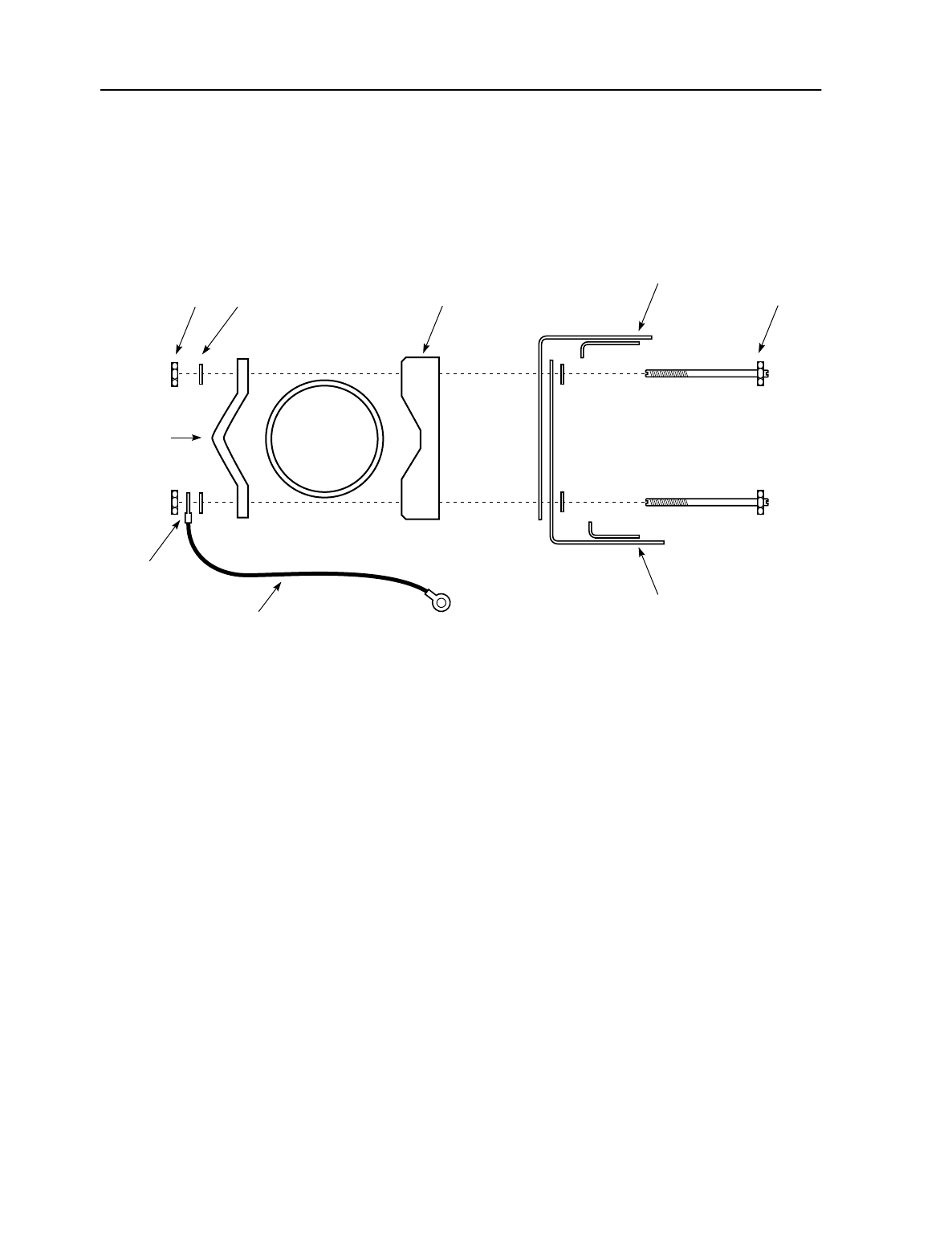
Figure 2-8: Type N lightning arrester
Figure 2-9 shows an RS-422 lightning arrester, used at the BTS site. Table 2-9 lists the
RS-422 lightning arrester physical connections.
Figure 2-9: RS-422 lightning arrester
Mounting
bracket
13193
Type F
lightning
arrester
Washer
Nut
Type N
lightning
arrester
Mounting
bracket
Washer
Nut
12989
6.35 mm (0.25 in.)
maximum
13.6 mm
(0.535 in.)
16.1 mm
(0.635 in.)
13110
LINE EQUIP
Ground wire
MainStreet Broadband Wireless Technical Practices 2. Equipment overview
NNP 95-4882-01-00-A Issue 1, April 1999
2-11
DRAFT
Table 2-9: RS-422 lightning arrester physical connections
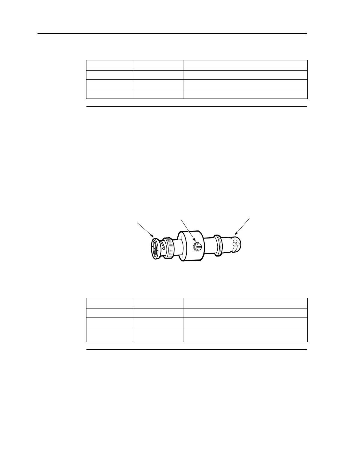
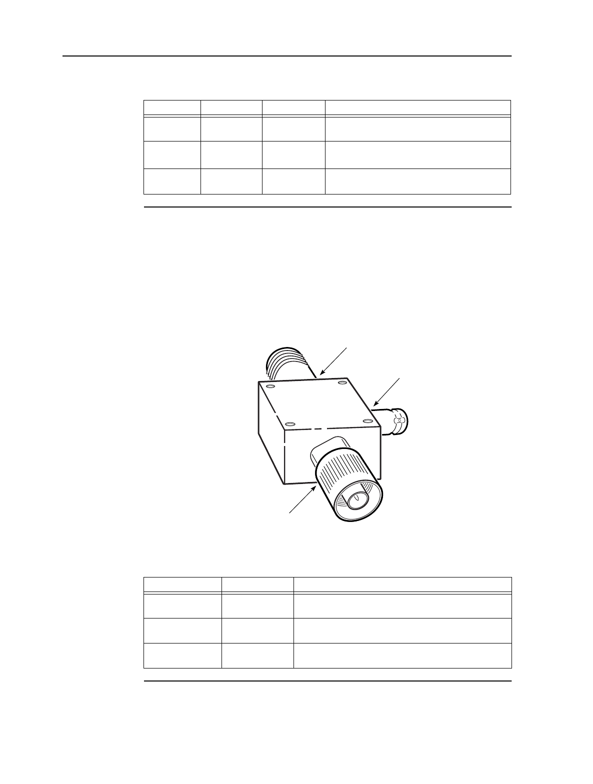
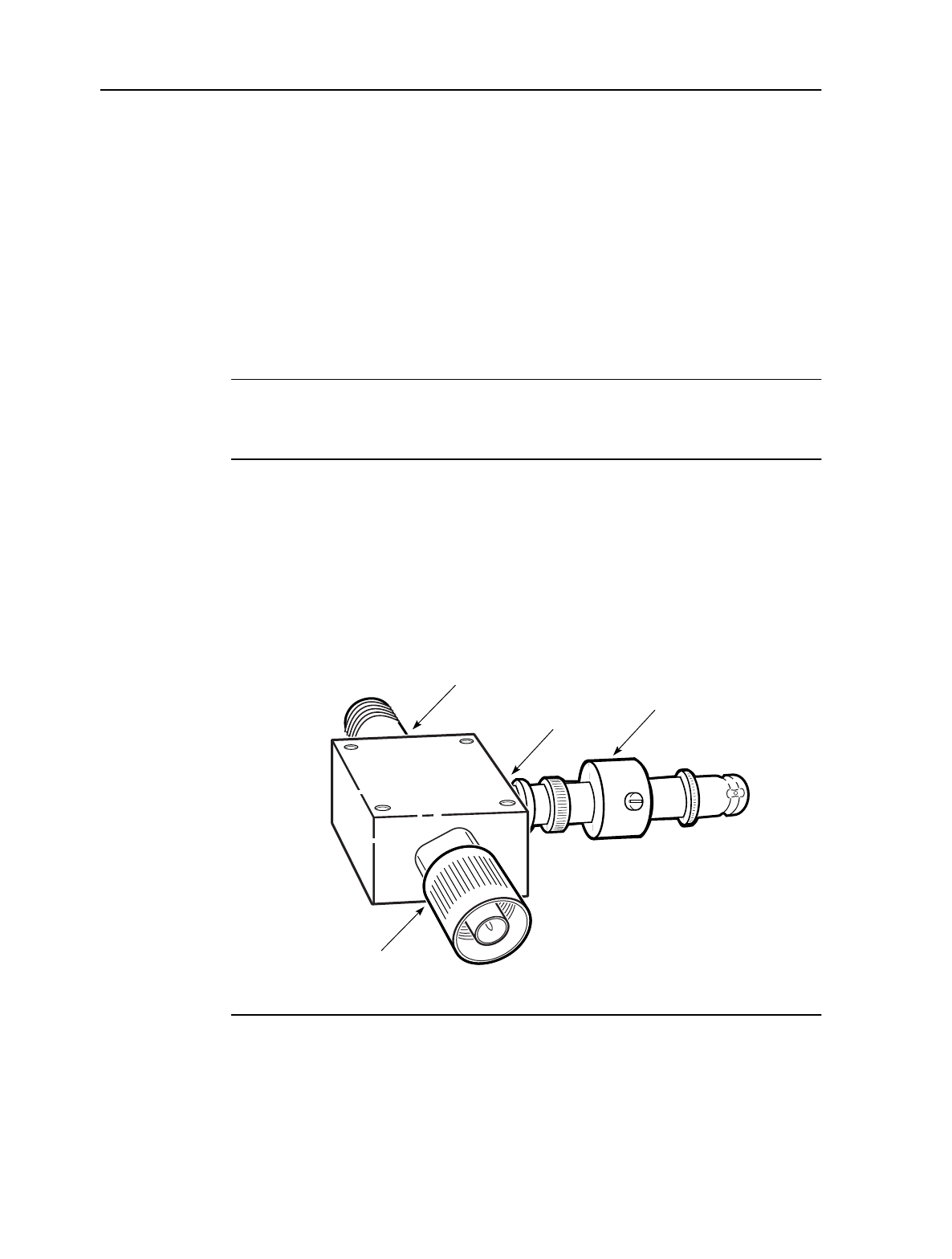
2.8 Surge protectors
Surge protectors filter power surges from the power supply, protecting the T-ARIC
card, OTU and ORUs from damage. Surge protectors connect directly to each Bias-T
via a BNC connector, and contain a gas discharge tube that must be replaced
regularly. Figure 2-10 shows a surge protector. Table 2-10 lists and describes the
connectors.
Figure 2-10: Surge protector
Table 2-10: Surge protector connectors
Name Type Purpose
LINE RS-422 Connects to the MAU RS-422 cable
EQUIP RS-422 Connects to the OTU or ORU RS-422 cable
Ground wire Insulated copper wire Connects to a ground source
Name Type Purpose
Bias-T BNC Connects to the MAU RS-422 cable
Bias-T power cable BNC Connects to the OTRU RS-422 cable
Ground screw Slot-head screw to
surge protector body Connects to a ground source
13060
Ground
screw To Bias-T
power cable
To Bias-T
2. Equipment overview MainStreet Broadband Wireless Technical Practices
Issue 1, April 1999 NNP 95-4882-01-00-A
2-12
DRAFT
2.9 OTU and ORU
The OTU is a transmitter radio that connects to an antenna. The OTU receives an IF
channel from a T-ARIC card, converts the signal to RF, and sends the signal to the
transmit antenna.
The ORU is a receiver radio that connects to an antenna. The ORU receives an RF
signal from one or more NIU transceivers, converts the signal to IF, and sends the
signal to the T-ARIC card.
Figure 2-11 shows the OTU and ORU connected to antennas.
Figure 2-11: OTU, ORU and antennas
Connectors
Table 2-11 describes the OTU and ORU connectors.
12694
100 Mhz
IF &
-48 V
RS-422
Data
100 Mhz
IF &
-48 V
RS-422
Data
OTU
Tx LED
IF and -48 V
connector
100 MHz reference
cable connector
RS-422 data
LEMO connector
ORU
IF and -48 V
connector
100 MHz reference
cable connector
RS-422 data
LEMO connector
MainStreet Broadband Wireless Technical Practices 2. Equipment overview
NNP 95-4882-01-00-A Issue 1, April 1999
2-13
DRAFT
Table 2-11: OTU and ORU connectors
2.10 Bias-T
The Bias-T provides -48 V power to the OTU and ORU at the BTS site. Figure 2-12
shows the Bias-T. Table 2-12 describes the connectors on the Bias-T.
Figure 2-12: Bias-T
Table 2-12: Bias-T connectors
Name Type Location Purpose
RS-422 Data RS-422 LEMO OTU and ORU
faceplates Connects to the T-ARIC card MAU
IF and -48V N(F) coaxial OTU and ORU
faceplates Connects to Tx broadband coaxial cable (OTU)
Connects to Rx broadband coaxial cable (ORU)
100 Mhz REF N(F) coaxial OTU and ORU
faceplates Connects to a synchronization reference cable that
connects to and synchronizes the OTU and ORU
Name Type Purpose
DC IN BNC(M) Connects to the power cable via an intermediate surge
arrester to provide a -48 V power input
DC OUT N(F) coaxial Connects to OTU or ORU to provide both -48 V power and
an RF signal connection
RF IN N(M) coaxial Connects to a Combiner/Splitter to provide RF signal
connection
12908
DC OUT
DC IN
RF IN
2. Equipment overview MainStreet Broadband Wireless Technical Practices
Issue 1, April 1999 NNP 95-4882-01-00-A
2-14
DRAFT
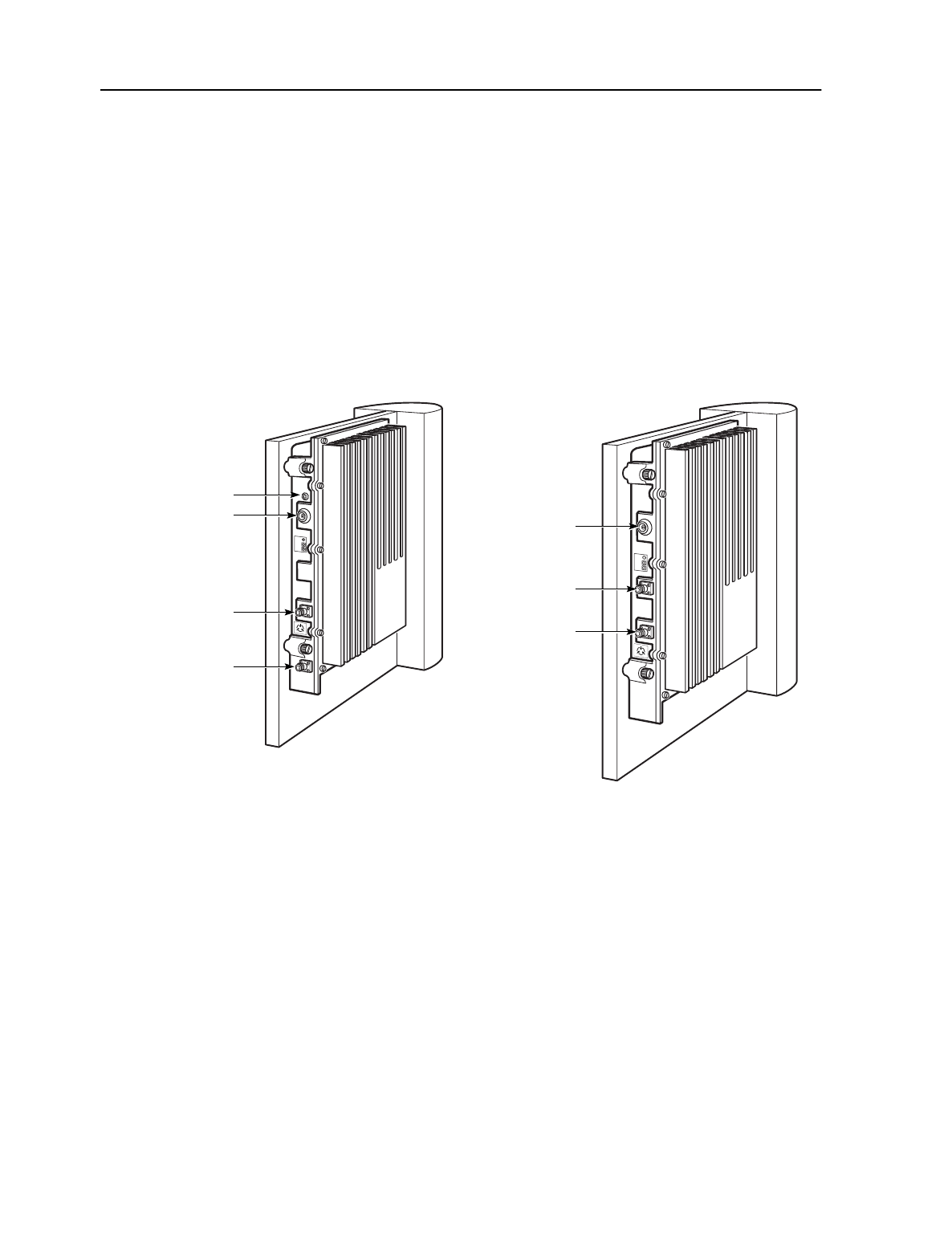
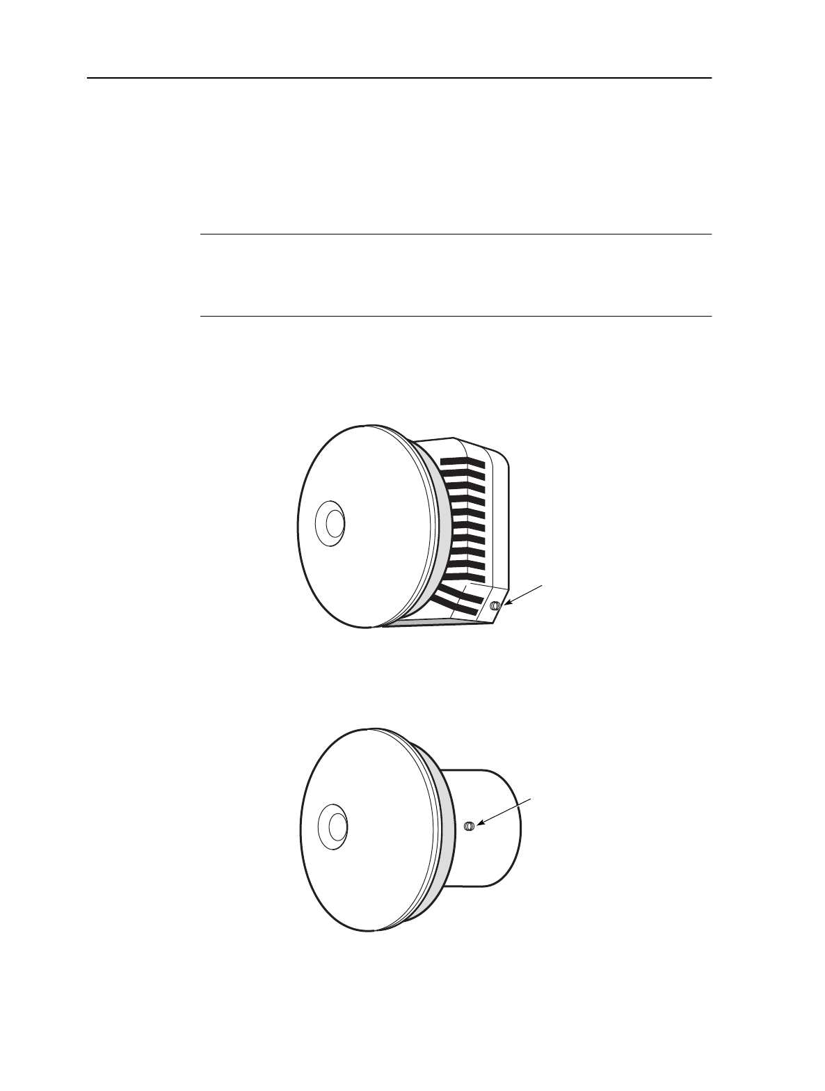
2.11 OTRU
In the downstream direction, the OTRU receives RF communications from the OTU,
converts the signal to IF, and sends the signal to the NIU. In the upstream direction,
the transceiver takes an IF signal from the NIU, converts the signal to RF, and
transmits the signal to the ORU.
Note
There are two types of OTRU transceivers: side-mount and back-mount. Both
OTRUs have the same part number, and are shipped according to availability.
Figure 2-13 shows a side-mount OTRU transceiver. Figure 2-14 shows a back-mount
OTRU transceiver.
Figure 2-13: Side-mount OTRU
Figure 2-14: Back-mount OTRU
12695
F(F) connector
13109
F(F) connector

MainStreet Broadband Wireless Technical Practices 2. Equipment overview
NNP 95-4882-01-00-A Issue 1, April 1999
2-15
DRAFT
Both OTRUs have a single F(F) connector that is used to connect the OTRU to the
NIU via an intermediate lightning arrester.


MainStreet Broadband Wireless Technical Practices 3. Installing the base transceiver station components
NNP 95-4882-01-00-A Issue 1, April 1999
3-1
DRAFT
3. Installing the base transceiver
station components
This chapter describes how to install the base transceiver station components.
3.1 BTS installation overview
BTS components and cables should be installed by qualified RF equipment
installers.
Siting
The MainStreet Broadband Wireless requires line -of-sight access between BTS
OTU/ORU equipment and CPE OTRUs. Each installation must be planned by
qualified RF engineers to optimize cell placement and minimize line-of-sight BTS to
CPE blockage by doing appropriate RF site planning, and using appropriate
equipment and procedures.
Customer-supplied equipment
Customers installing a BTS will need to supply:
•attenuators
•coaxial cable that runs from the 12:2 Combiner/Splitters to the outdoor radios
•RS-422 cable that runs from the MAU to the OTU and ORU
•a grounded entry point
•ground wires and connectors
•weatherproof cable entry panel(s)
•poles or towers for ORU, OTU and OTRU mounting
•miscellaneous supplies (such as butyl electrical tape, cable cutter, wire stripper
and crimping tool)
Broadband cables
Because many factors are associated with choosing a suitable coaxial cable,
customers will be advised by Newbridge of the manufacturers and manufacturer
part numbers recommended for each cable assembly.

3. Installing the base transceiver station components MainStreet Broadband Wireless Technical Practices
Issue 1, April 1999 NNP 95-4882-01-00-A
3-2
DRAFT
The cable path from the T-ARIC card to the OTU or ORU must provide a fixed
common loss. The losses are:
•downstream: 27 ±1 dB at 2050 MHz
•upstream: 24 ±1 dB at 900 MHz
If the total loss falls short of these values, attenuators must be installed.
Grounded entry point
Each BTS requires a grounded entry point in order to ground BTS components and
cables. Refer to local electrical code requirements when choosing a grounded entry
point for the BTS.
OTU and ORU radios
The OTU and ORU radios are designed to be installed on antenna tower(s), masts,
buildings or other appropriate fixtures. The MainStreet Broadband Wireless system
supports both simplex and redundant OTU and ORU configurations.
The distance between the T-ARIC card and the outdoor transmitter and receiver can
be over 200 m (656 ft) with the use of high-quality, low-loss coaxial cable. This allows
the RF equipment to be located on a tower or on a building while the T-ARIC card
and MainStreetXpress 36170 shelves are installed indoors.
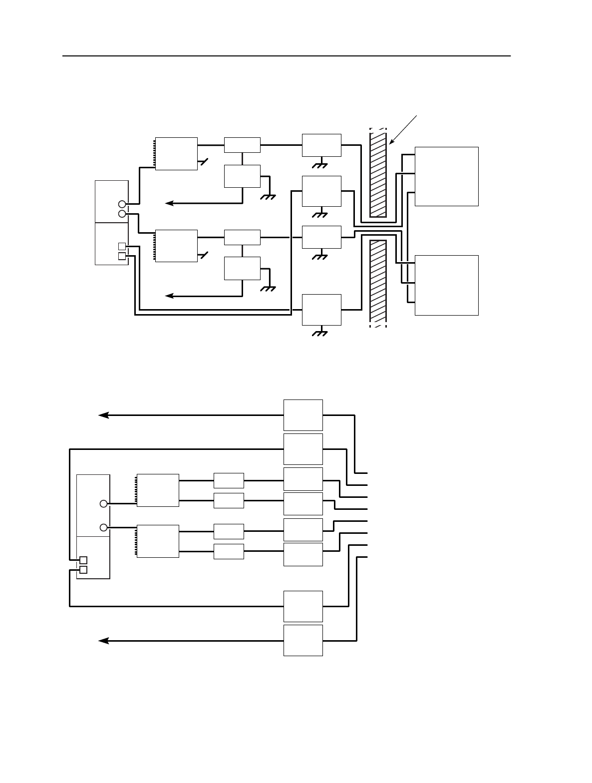
3.2 Installing BTS components
Figure 3-1 shows a diagram of a typical simplex BTS configuration. Figure 3-2 shows
a diagram of a redundant BTS configuration. Grounding, surge protection and
power connection are similar to the simplex system. Table 3-1 lists the BTS
components and part numbers. For information on how to connect synchronization
reference cables to redundant OTU/ORUs, see chapter 9.
MainStreet Broadband Wireless Technical Practices 3. Installing the base transceiver station components
NNP 95-4882-01-00-A Issue 1, April 1999
3-3
DRAFT
Figure 3-1: Simplex BTS components and cables
Figure 3-2: Redundant BTS components and cables
T-ARIC
Tx
Rx
Bias-T
Bias-T power cable
-48 V
Bias-T power cable
-48 V
Surge
protector
Lightning
arrester RS-422 data
IF + -48 V
Synchronization
reference
OTU
RS-422 data
IF + -48 V
Synchronization
reference
ORU
Bias-T
Surge
protector
Rx 12:2
Combiner/
Splitter
MAU
ORU
OTU
Tx 12:2
Combiner/
Splitter
RS-422
lightning
arrester
Lightning
arrester
RS-422
lightning
arrester
13004
Exterior
wall
Tx
T-ARIC
Rx
Bias-T To OTU RS-422 Data connector
To software selected Tx Control T-ARIC MAU
To software selected Rx Control T-ARIC MAU
To R-OTU RS-422 Data connector
To R-OTU IF + -48 V Data connector
To OTU IF + -48 V Data connector
To ORU IF + -48 V Data connector
To R-ORU IF + -48 V Data connector
To ORU RS-422 Data connector
To R-ORU RS-422 Data connector
Where:
R-OTU is a redundant OTU
R-ORU is a redundant ORU
Bias-T
Lightning
arrester
Lightning
arrester
Bias-T
Bias-T
Lightning
arrester
Lightning
arrester
Rx 12:2
Combiner/
Splitter
OTU
ORU
Tx 12:2
Combiner/
Splitter
13097
RS-422
lightning
arrester
RS-422
lightning
arrester
RS-422
lightning
arrester
RS-422
lightning
arrester

3. Installing the base transceiver station components MainStreet Broadband Wireless Technical Practices
Issue 1, April 1999 NNP 95-4882-01-00-A
3-4
DRAFT
Table 3-1: BTS equipment summary (per sector)
3.3 BTS installation tasks
Perform the following installation tasks to install the BTS:
•install the MAU
•attach the antenna to the OTU/ORU
•attach the ORU and OTU to the pole assembly
•mount the lightning arresters
•connect the surge protectors to the Bias-Ts
•connect the Bias-Ts to the 12:2 Combiner/Splitter
•connect the BTS cables
Item Number for simplex
OTU/ORU system Number for
redundant
OTU/ORU system
Part number
12:2 Combiner/Splitter 2 2 90-6659-01
2:1 Combiner/Splitter 0 2 90-6734-01
Lightning arrester 2 4 90-6517-01
OTU 1 2 90-4568
ORU 1 2 90-4567
Antennas 1
1
2
2
90-4563-01 (horizontal polarization)
90-4564-01 (vertical polarization)
RS-422 lightning arrester 2 4 90-6519-01
Surge protector 2 4 90-6739-01
Bias-T 2 4 90-6516-01
Bias-T power cable 2 4 90-6518-01
MAU 1 to 12 1 to 12 90-6474-01
T-ARIC card 1 to 12 1 to 12 90-6206-01
MainStreet Broadband Wireless Technical Practices 4. Installing the MAU
NNP 95-4882-01-00-A Issue 1, April 1999
4-1
DRAFT
4. Installing the MAU
This chapter describes how to install the MAU on the MainStreetXpress 36170 shelf.
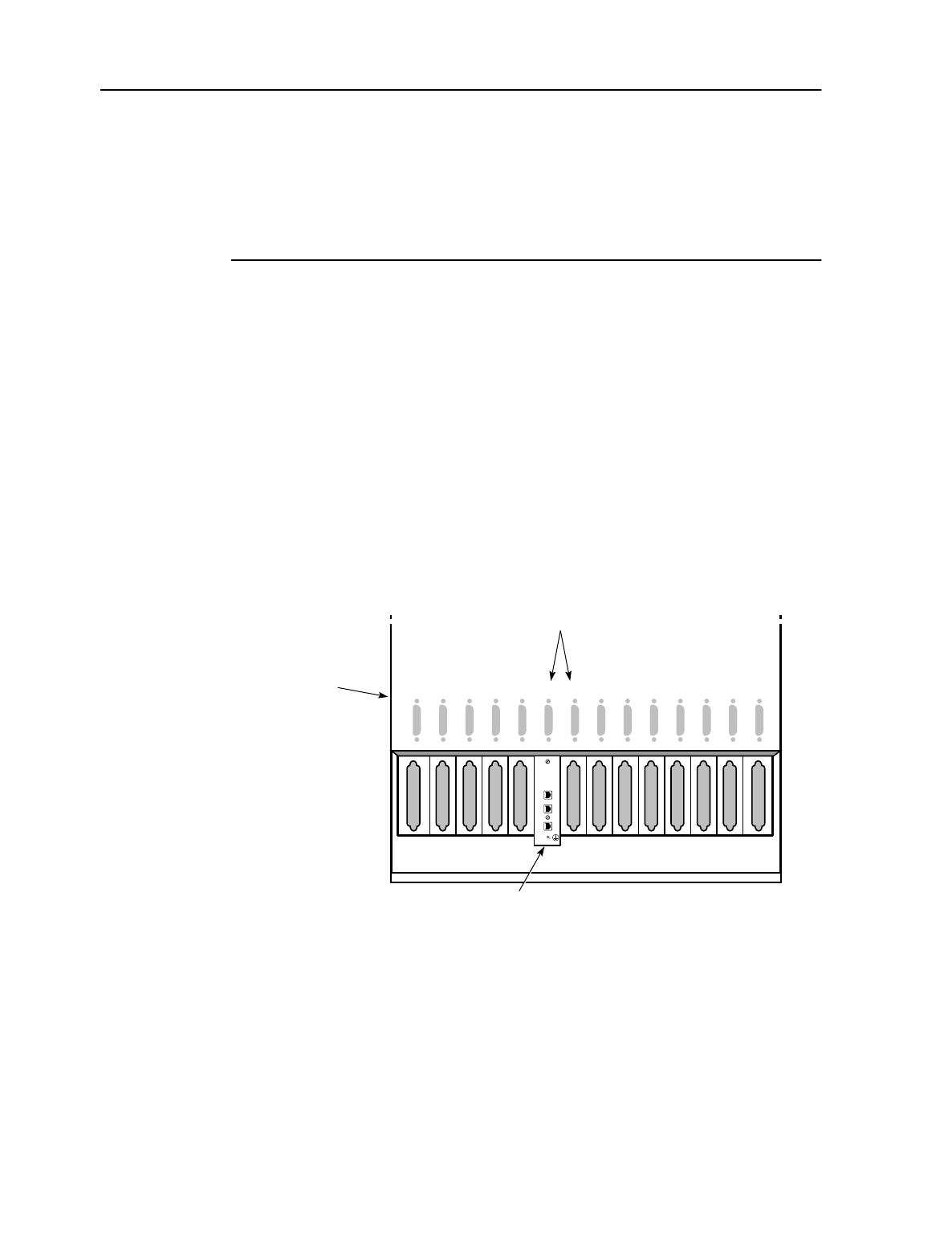
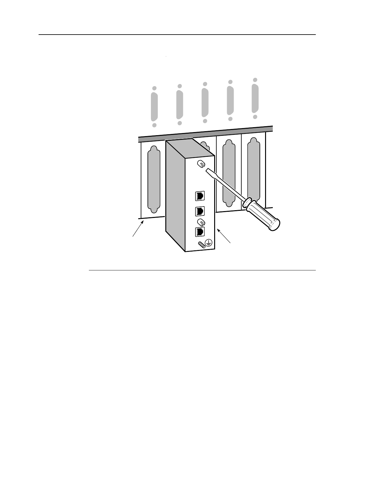
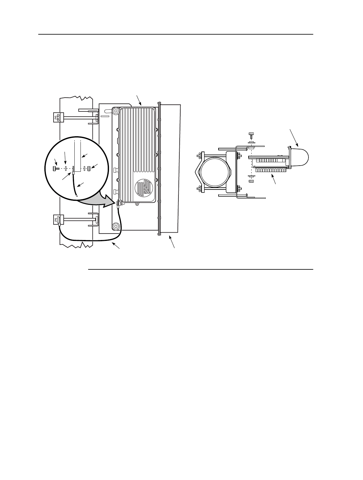
4.1 To install the MAU
The MAU is installed on the back of the MainStreetXpress 36170 shelf, directly
behind each T-ARIC card. Because a T-ARIC card uses two slots, two slot connector
locations are available for the MAU. Always install the MAU in the even-numbered
slot.
1. Locate the slot pair for the T-ARIC card, and align the MAU for attachment
behind the even-numbered slot of the slot pair, as shown in Figure 4-1. If the
T-ARIC card is already installed in the slot, ensure that the DSUB connector on
the back of the MAU aligns correctly with the connector on the T-ARIC card.
Figure 4-1: MAU location on the MainStreetXpress 36170 shelf
2. Tighten the two MAU captive screws, as shown in Figure 4-2.
13001
Hy121110987654321Hx
ORU
OTU
ORU
OTU
MAU
MainStreetXpress
36170 shelf
T-ARIC card
in slots 7/8
4. Installing the MAU MainStreet Broadband Wireless Technical Practices
Issue 1, April 1999 NNP 95-4882-01-00-A
4-2
DRAFT
Figure 4-2: Tightening the MAU captive screws
13002
MainStreetXpress
36170 shelf MAU
98765
ORU
Tx
Rx
OTU
ORU
OTU

MainStreet Broadband Wireless Technical Practices 5. Attaching an OTU or ORU to an antenna
NNP 95-4882-01-00-A Issue 1, April 1999
5-1
DRAFT
5. Attaching an OTU or ORU to an
antenna
Each OTU or ORU should be connected to an antenna before the antenna is mounted
on the BTS pole assembly.
If the OTU or ORU is being installed on an antenna that is already mounted and
aligned on a pole, do not remove the antenna from the pole. Install the OTU or ORU
directly on the mounted antenna.
Note 1
All procedures should be performed in a clean indoor lab environment, on a
workbench suitable for electronic assembly.
Note 2
Do not remove the shipping caps from the coaxial and RS-442 connectors on the
OTU and ORU until the BTS cables are ready for attachment.
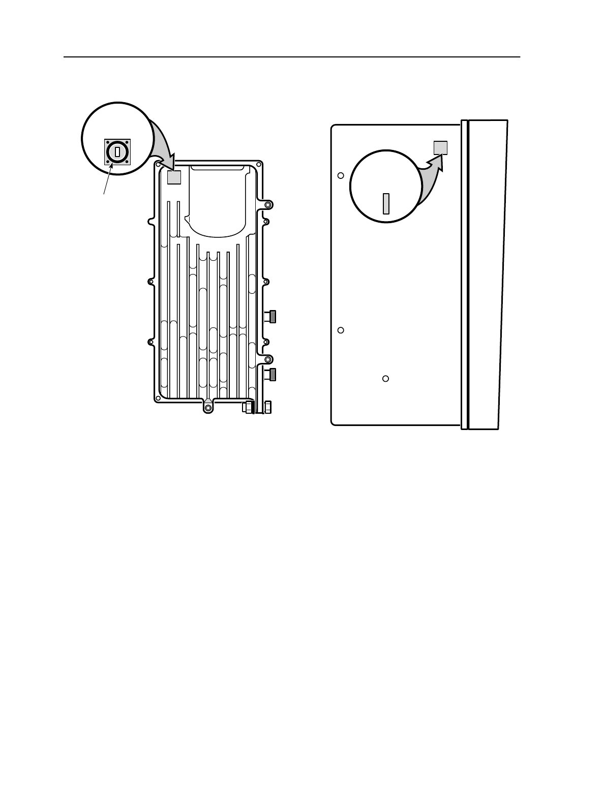
5.1 Attaching the OTU or ORU to an antenna
1. Remove the RF channel cover from the OTU or ORU and remove the RF
channel plug from the antenna . Figure 5-1 shows the locations of the plug and
the cover.
5. Attaching an OTU or ORU to an antenna MainStreet Broadband Wireless Technical Practices
Issue 1, April 1999 NNP 95-4882-01-00-A
5-2
DRAFT
Figure 5-1: Removing the plugs and covers
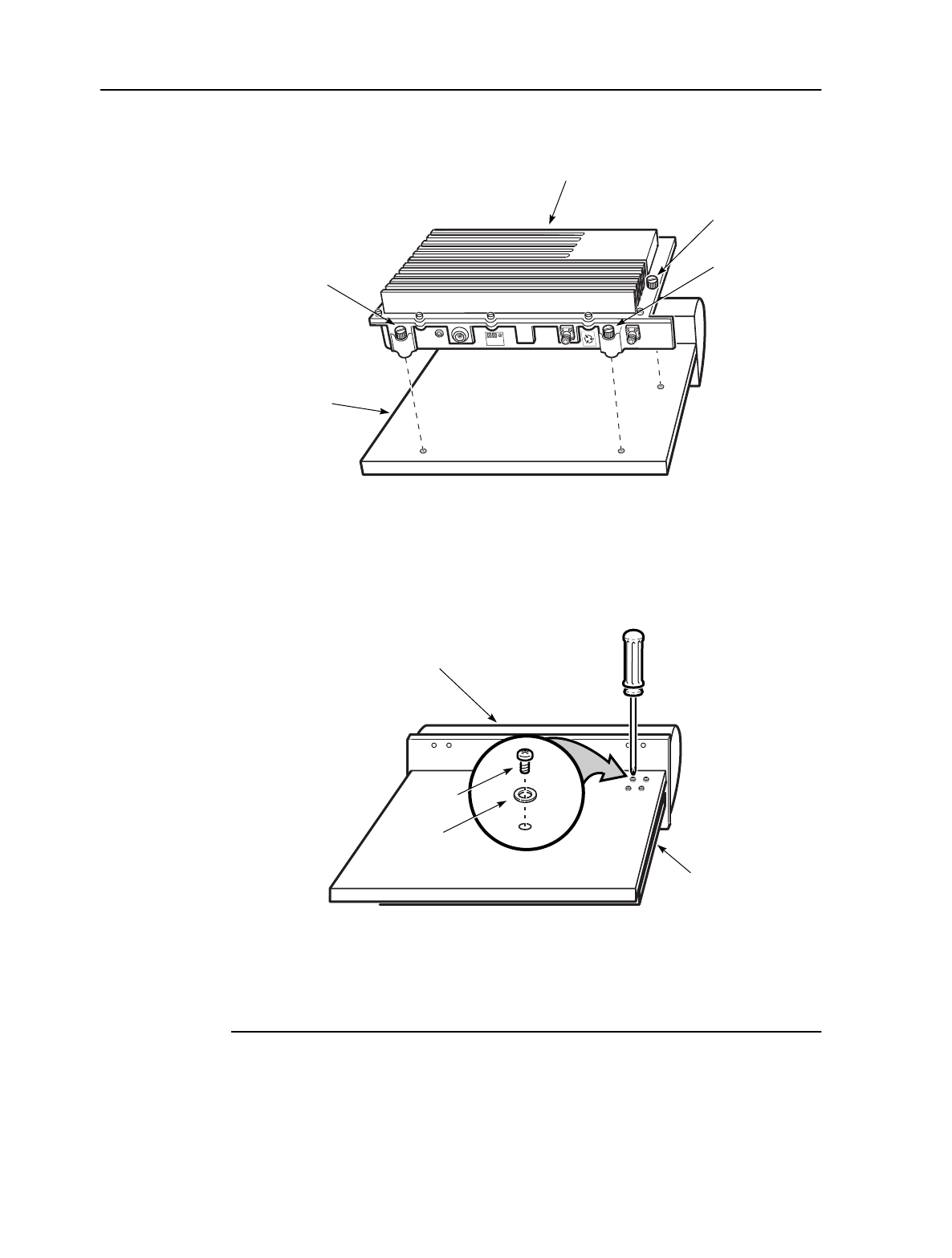
2. Place the antenna on a flat surface.
3. Place the provided O-ring on the O-ring seal seat around the OTU or ORU RF
channel. Ensure that the O-ring remains in place during the entire procedure.
4. Place the radio on the antenna as indicated in Figure 5-2. Turn each captive
screw until there is only a small gap between the radio and the antenna. This
gap must be small enough that the O-ring does not move.
RF channel
with cover
removed
OTU/ORU
radio
Antenna
RF channel
with plug
removed
13005
O-ring seal
seat
MainStreet Broadband Wireless Technical Practices 5. Attaching an OTU or ORU to an antenna
NNP 95-4882-01-00-A Issue 1, April 1999
5-3
DRAFT
Figure 5-2: Tightening the captive screws
5. Turn over the OTU or ORU and antenna as shown in Figure 5-3, and ensure that
the weight of the antenna is put entirely on the radio. Insert and tighten the four
RF channel screws as shown in the diagram.
Figure 5-3: RF channel screws
6. Turn the OTU/ORU and antenna assembly over, and tighten each of the three
captive screws on the radio.
7. Ensure that each of the RF channel screws is tight.
13006
100 Mhz
IF &
-48 V
RS-422
Data
Captive
screw
Antenna
OTU/ORU
Captive
screw
Captive
screw
Antenna
13007
RF
channel
screw
Washer
OTU/ORU

MainStreet Broadband Wireless Technical Practices 6. Installing the BTS antenna assembly
NNP 95-4882-01-00-A Issue 1, April 1999
6-1
DRAFT
6. Installing the BTS antenna
assembly
This chapter describes how to:
•attach the BTS antenna mounting hardware to a pole
•connect the antenna and OTU/ORU assembly to the mounting hardware
•connect a ground strap between the OTU/ORU and the mounting hardware
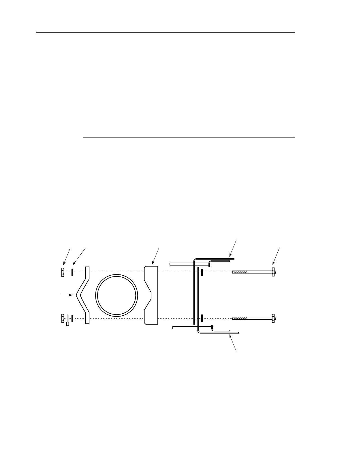
6.1 Installing the BTS mounting hardware
The BTS mounting hardware is composed of two assemblies: the top support arm
bracket assembly, and the bottom support arm bracket assembly.
1. Attach the top support arm bracket assembly as shown in Figure 6-1.
Figure 6-1: Attaching the top support arm bracket assembly
Nut Washer
Pole
Front plate
Antenna
support arm
Optional antenna support arm
for a redundant radio
Bolt
13113
Backing
plate
6. Installing the BTS antenna assembly MainStreet Broadband Wireless Technical Practices
Issue 1, April 1999 NNP 95-4882-01-00-A
6-2
DRAFT
2. Install the bottom support-arm bracket assembly as shown in Figure 6-2. The
ground strap used must conform to local grounding and electrical safety
guidelines.
Figure 6-2: Attaching the bottom support arm bracket assembly and ground strap
Nut Washer
Pole
Front plate
Antenna
support arm
Optional
antenna
support arm for
a redundant radio
Circular
lug
Ground
strap
Bolt
13183
Backing
plate
MainStreet Broadband Wireless Technical Practices 6. Installing the BTS antenna assembly
NNP 95-4882-01-00-A Issue 1, April 1999
6-3
DRAFT
3. Attach the OTU/ORU and antenna assembly to the top and bottom support
arm assembly as shown in Figure 6-3.
Figure 6-3: Connecting the OTU/ORU, antenna and ground strap
13114
Antenna
OTU/ORU
OTU/ORU
Antenna
Ground strap
OTU/
ORU
Ground
strap
Bolt
Nut
Circular
lug
Washer

MainStreet Broadband Wireless Technical Practices 7. Installing Bias-Ts and surge protectors
NNP 95-4882-01-00-A Issue 1, April 1999
7-1
DRAFT
7. Installing Bias-Ts and surge
protectors
This chapter describes how to:
•connect the surge protector to the Bias-T
•connect the Bias-T to the 12:2 Combiner/Splitter
•connect the surge protector ground wire
Note
A surge protector must be installed on every Bias-T.
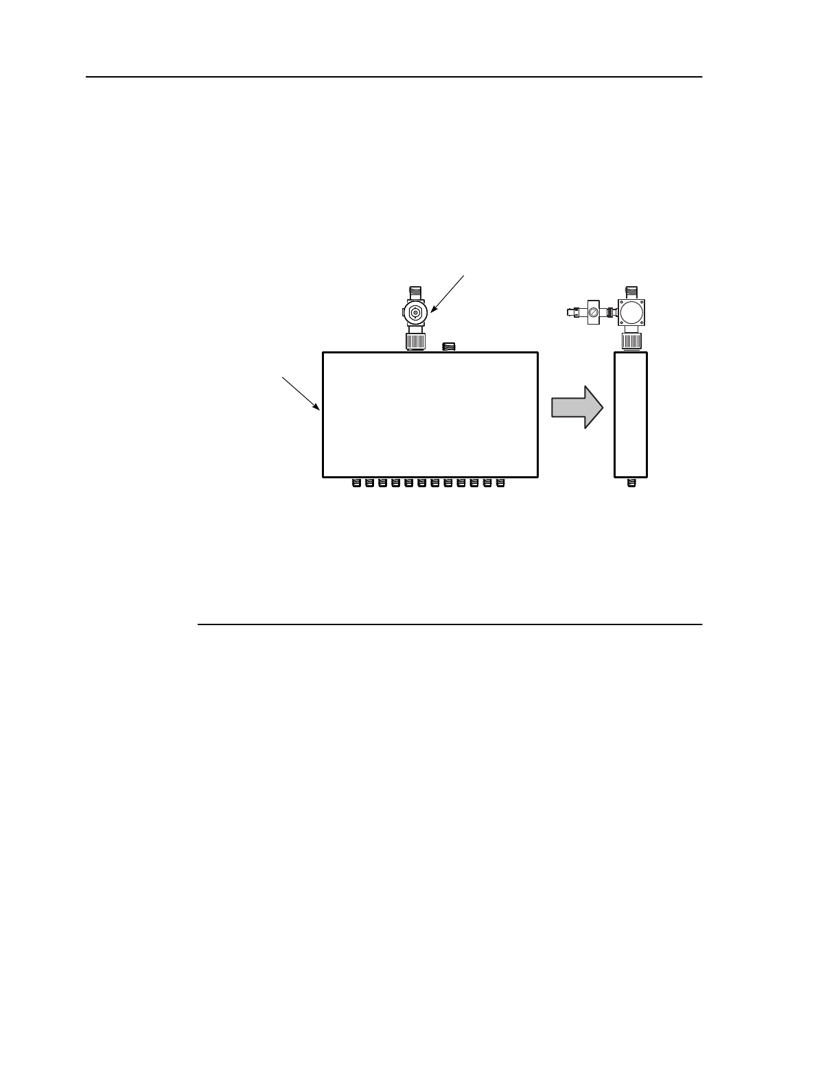
7.1 Connecting the surge protector to the Bias-T
To correctly connect a surge protector to a Bias-T, connect the male BNC connector
on the surge protector to the DC IN connector on the Bias-T as shown in Figure 7-1.
Figure 7-1: Connecting the surge protector
13059
Surge protector
RF IN
DC OUT
DC IN
7. Installing Bias-Ts and surge protectors MainStreet Broadband Wireless Technical Practices
Issue 1, April 1999 NNP 95-4882-01-00-A
7-2
DRAFT
7.2 Connecting the Bias-T to the 12:2 Combiner/Splitter
1. Position the Bias-T RF IN connector to one of the two Combiner/Splitter Bias-T
connectors, as shown in Figure 7-2 (surge protector positioned at a right angle
to the 12:2 Combiner/Splitter).
Figure 7-2: Connecting the Bias-T to the Combiner/Splitter
2. Tighten the coupling on the RF IN connector until the Bias-T is firmly connected
and does not rotate.
3. Install a 50 Ω terminator on the second 12:2 Combiner/Splitter connector if it is
not used for a redundant OTU or ORU Bias-T.
7.3 Connecting the surge protector ground wire
1. Place the 12:2 Combiner/Splitter assembly in a permanent location at the
MainStreetXpress 36170 shelf. If the 12:2 Combiner/Splitter is moved after the
surge protector ground wire is connected, a new ground wire may need to be
used if the previous wire is not long enough to run to the new 12:2
Combiner/Splitter location.
2. Measure a length of insulated copper wire that is long enough to run from the
closest safety ground to the surge protector.
3. Add a ring lug to one end of the ground wire, and connect it to the surge
protector as shown in Figure 7-3.
13058
Front Side
Bias-T and
surge protector
12:2
Combiner/
Splitter

MainStreet Broadband Wireless Technical Practices 7. Installing Bias-Ts and surge protectors
NNP 95-4882-01-00-A Issue 1, April 1999
7-3
DRAFT
Figure 7-3: Surge protector ground connection
4. Connect the other end of the ground wire to the building ground.
13062
Ground
wire
Ground
screw
Surge
protector
Washer
Ring
lug


MainStreet Broadband Wireless Technical Practices 8. Installing broadband cable lightning arresters
NNP 95-4882-01-00-A Issue 1, April 1999
8-1
DRAFT
8. Installing broadband cable
lightning arresters
This chapter describes how to connect BTS broadband cable lightning arresters to a
grounded entry point. To correctly install a lightning arrester:
•connect the lightning arrester mounting brackets to the BTS grounding plate
•install the lightning arresters in the mounting brackets
8.1 Connecting the mounting bracket to the BTS grounding
plate
Lightning arresters must be secured to a copper BTS grounding plate using
mounting brackets. Connect a mounting bracket to the copper plate for each
lightning arrester used in the system, as shown in Figure 8-1.
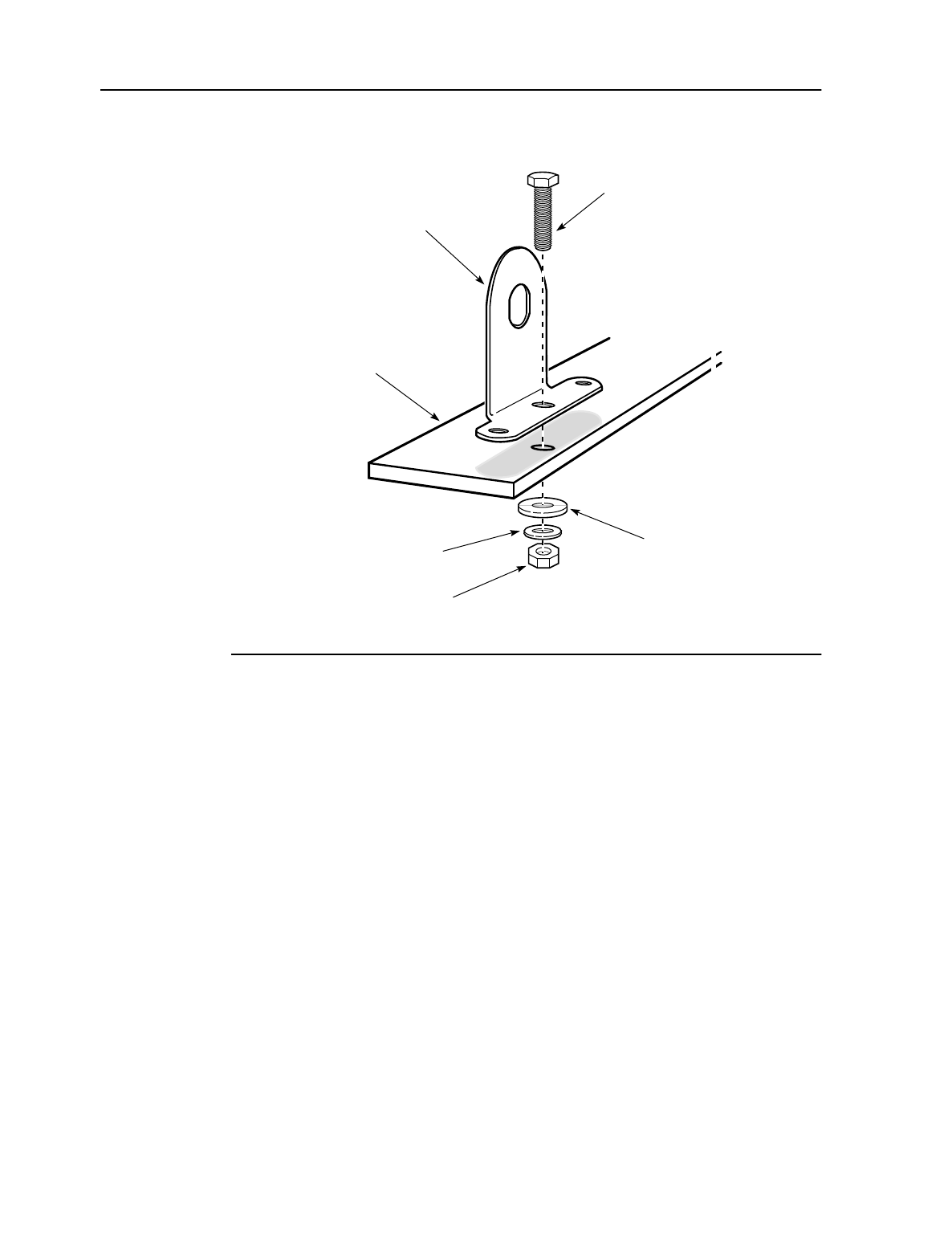
8. Installing broadband cable lightning arresters MainStreet Broadband Wireless Technical Practices
Issue 1, April 1999 NNP 95-4882-01-00-A
8-2
DRAFT
Figure 8-1: Connecting the mounting brackets to the grounding plate
8.2 Installing the lightning arrester in the adapter bracket
Before cables are connected to the lightning arrester, install each lightning arrester
in the mounting brackets, as shown in Figures 8-2 and 8-3. Figure 8-3 shows the
lightning arresters with cables connected.
Type N
mounting bracket
Copper
grounding plate
Bronze
lockwasher
3/8 in.
bronze bolt
12990
Copper
washer
3/8 in.
bronze nut
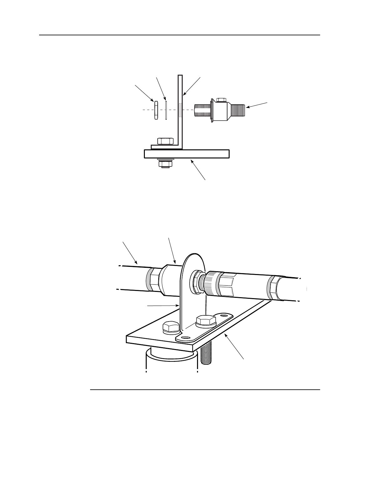
MainStreet Broadband Wireless Technical Practices 8. Installing broadband cable lightning arresters
NNP 95-4882-01-00-A Issue 1, April 1999
8-3
DRAFT
Figure 8-2: Connecting the lightning arrester to the adapter bracket
Figure 8-3: Installed and connected lightning arrester
Type N
lightning
arrester
Mounting
bracket
Washer
Nut
Copper
grounding plate
13179
Mounting
bracket
Lightning
arrester
Broadband
cable
Copper
grounding plate
12916

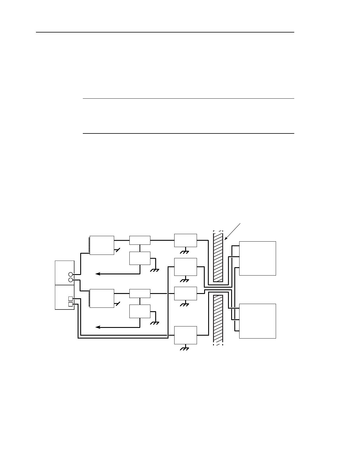
MainStreet Broadband Wireless Technical Practices 9. BTS cable connections
NNP 95-4882-01-00-A Issue 1, April 1999
9-1
DRAFT
9. BTS cable connections
This procedure describes how to select cable types, and how to connect cables
between BTS components.
Note
All outdoor cable connections should be wrapped in butyl electrical tape to protect
against moisture.
9.1 BTS cables
Figure 9-1 shows a simplex OTU/ORU BTS configuration. Figure 9-2 shows a
redundant OTU/ORU BTS configuration. The cables shown in the diagram must be
connected between the components.
Figure 9-1: Simplex OTU/ORU BTS components and cables
T-ARIC
Tx
Rx
Bias-T
Bias-T power cable
-48 V
Bias-T power cable
-48 V
Surge
protector
Lightning
arrester RS-422 data
IF + -48 V
Synchronization
reference
OTU
RS-422 data
IF + -48 V
Synchronization
reference
ORU
Bias-T
Surge
protector
Rx 12:2
Combiner/
Splitter
MAU
ORU
OTU
Tx 12:2
Combiner/
Splitter
RS-422
lightning
arrester
Lightning
arrester
RS-422
lightning
arrester
13004
Exterior
wall
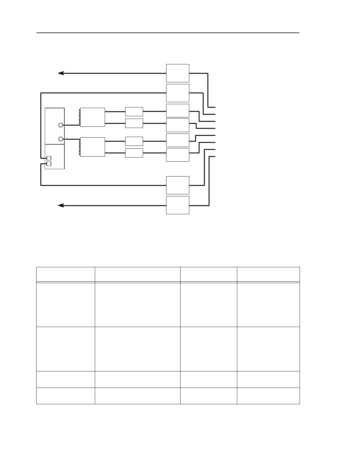
9. BTS cable connections MainStreet Broadband Wireless Technical Practices
Issue 1, April 1999 NNP 95-4882-01-00-A
9-2
DRAFT
Figure 9-2: Redundant OTU/ORU BTS components and cables
Table 9-1 lists the cables used to connect the OTU, ORU and the T-ARIC card.
Table 9-2 lists the part numbers for the BTS cable connectors.
Table 9-1: BTS cables
Tx
T-ARIC
Rx
Bias-T To OTU RS-422 Data connector
To software selected Tx Control T-ARIC MAU
To software selected Rx Control T-ARIC MAU
To R-OTU RS-422 Data connector
To R-OTU IF + -48 V Data connector
To OTU IF + -48 V Data connector
To ORU IF + -48 V Data connector
To R-ORU IF + -48 V Data connector
To ORU RS-422 Data connector
To R-ORU RS-422 Data connector
Where:
R-OTU is a redundant OTU
R-ORU is a redundant ORU
Bias-T
Lightning
arrester
Lightning
arrester
Bias-T
Bias-T
Lightning
arrester
Lightning
arrester
Rx 12:2
Combiner/
Splitter
OTU
ORU
Tx 12:2
Combiner/
Splitter
13097
RS-422
lightning
arrester
RS-422
lightning
arrester
RS-422
lightning
arrester
RS-422
lightning
arrester
Physical path Intermediate cables Connectors Recommended cable
specification
OTU IF and -48 V to 12:2
Combiner/Splitter OTU to lightning arrester
Lightning arrester to Bias-T
N(M) - N(M)
N(M) - N(M)
LDF4-50A
LDF5-50A
LDF6-50A
CR 50-540-PE
CR-50-1070-PE
CR-50-1873-PE
ORU IF and -48 V to 12:2
Combiner/Splitter ORU to lightning arrester
Lightning arrester to Bias-T
N(M) - N(M)
N(M) - N(M)
LDF4-50A
LDF5-50A
LDF6-50A
CR 50-540-PE
CR-50-1070-PE
CR-50-1873-PE
12:2 Combiner/Splitter to
T-ARIC Tx connector n/a N(M) - SMA(M) 90-6656-01 (3 m [10 ft])
90-6656-02 (6 m [20 ft])
12:2 Combiner/Splitter to
T-ARIC Rx connector n/a N(M) - SMA(M) 90-6656-01 (3 m [10 ft])
90-6656-02 (6 m [20 ft])

MainStreet Broadband Wireless Technical Practices 9. BTS cable connections
NNP 95-4882-01-00-A Issue 1, April 1999
9-3
DRAFT
Table 9-2: BTS cable connectors
9.2 Connecting BTS broadband cables
Note
Outdoor BTS broadband cables should be grounded via the outer conductor every
15 m (50 ft).
BTS cables, connectors and equipment must provide a fixed decibel loss in both the
upstream and downstream directions. The downstream losses must total 27 dB at
2050 MHz, ± 1 dB. The upstream losses must total 24 dB at 900 MHz, ± 1 dB. If the
total loss is less than the required value, attenuators are installed between SMA
cables and the 12:2 Combiner/Splitters.
In order to maintain a fixed cable loss, different cable types are selected depending
on the distance between the T-ARIC card and the OTU and ORU.
Table 9-3 shows the recommended cable types for specific distances. Tables 9-4
through 9-9 show how the fixed loss is calculated for each type of cable.
OTU RS-422 connector to
T-ARIC MAU Tx
connector
OTU to RS-422 lightning arrester
RS-422 lightning arrester to MAU OTU
connector
LEMO - RJ45
RJ45 - RJ45
Delco 398087P
ORU RS-422 connector to
T-ARIC MAU Rx
connector
ORU to RS-422 lightning arrester
RS-422 lightning arrester to MAU ORU
connector
LEMO - RJ45
RJ45 - RJ45
Delco 398087P
ORU to OTU 100 MHz reference cable N(M) - N(M) LDF4-50A
CR-50-540 PE
Bias-T power cable n/a BNC(M) - lug connectors 90-6516-01
Physical path Intermediate cables Connectors Recommended cable
specification
Connector Part number
N(M) 90-6657-01 (1 connector)
90-6657-02 (25 connectors)
LEMO 90-6816-01
RJ-45 90-6815-01

9. BTS cable connections MainStreet Broadband Wireless Technical Practices
Issue 1, April 1999 NNP 95-4882-01-00-A
9-4
DRAFT
Table 9-3: Cable lengths and types
Table 9-4: LDF4-50A cable (60 m [196 ft]) decibel loss calculations
Distance Cable type Supplier Loss calculations
60 m (196 ft) LDF4-50A Andrew Table 9-4
120 m (394 ft) LDF5-50A Andrew Table 9-5
150 m (492 ft) LDF6-50A Andrew Table 9-6
70 m (230 ft) CR50-540-PE CommScope Table 9-7
120 m (394 ft) CR50-1070-PE CommScope Table 9-8
200 m (656 ft) CR50-1873-PE CommScope Table 9-9
BTS item Max
VSWR
(
x
:1)
Downstream
loss
(2050 MHz)
(dB)
Upstream
loss
(900 MHz)
(dB)
Downstream
insertion and
coupling loss
(2050 MHz)
(dB)
Upstream
insertion
and
coupling
loss
(900 MHz)
(dB)
Downstream
VSWR
corrected
loss
(2050 MHz)
(dB)
Upstream
VSWR
corrected
loss
(900 MHz)
(dB)
1 × T-ARIC SMA
cable (3 m [10 ft]) 1.35 0.467 .333 1.40 1.00 1.46 1.05
1 × OTU 12.2
Combiner/Splitter 1.30 3.000 0.000 14.00 0.00 17.10 0.00
1 × ORU 12:2
Combiner/Splitter 1.30 0.000 2.500 0.00 14.00 0.00 16.59
1 × Bias-T 1.30 1.000 1.000 1.00 1.00 1.03 1.03
1 × surge protector 1.10 0.200 0.200 0.20 0.20 0.20 0.20
1 × cable LDF4-50A
(60 m [196 ft])
1.20 0.065 0.040 7.75 4.80 7.88 4.88
4 × cable connectors 1.20 0.200 0.200 0.80 0.80 0.94 0.94
Total loss — — — 25.15 21.80 28.63 24.69

MainStreet Broadband Wireless Technical Practices 9. BTS cable connections
NNP 95-4882-01-00-A Issue 1, April 1999
9-5
DRAFT
Table 9-5: LDF5-50A cable (120 m [394 ft]) decibel loss calculations
BTS item Max
VSWR
(
x
:1)
Downstream
loss
(2050 MHz)
(dB)
Upstream
loss
(900 MHz)
(dB)
Downstream
insertion and
coupling loss
(2050 MHz)
(dB)
Upstream
insertion
and
coupling
loss
(900 MHz)
(dB)
Downstream
VSWR
corrected
loss
(2050 MHz)
(dB)
Upstream
VSWR
corrected
loss
(900 MHz)
(dB)
1 × T-ARIC SMA
cable (3 m [10 ft]) 1.35 0.467 .333 1.40 1.00 1.46 1.05
1 × 12:2 OTU
Combiner/Splitter 1.30 3.000 0.000 14.00 0.00 17.10 0.00
1 × 12:2 ORU
Combiner/Splitter 1.30 0.000 2.500 0.00 14.00 0.00 16.59
1 × Bias-T 1.30 1.000 1.000 1.00 1.00 1.03 1.03
1 × surge
protector 1.10 0.200 0.200 0.20 0.20 0.20 0.20
1 × cable
LDF5-50A
(120 m [394 ft])
1.20 0.065 0.040 7.75 4.80 7.88 4.88
4 × cable
connectors 1.20 0.200 0.200 0.80 0.80 0.94 0.94
Total loss — — — 25.15 21.80 28.63 24.69

9. BTS cable connections MainStreet Broadband Wireless Technical Practices
Issue 1, April 1999 NNP 95-4882-01-00-A
9-6
DRAFT
Table 9-6: LDF6-50A cable (150 m [492 ft]) decibel loss calculations
BTS item Max
VSWR
(
x
:1)
Downstream
loss
(2050 MHz)
(dB)
Upstream
loss
(900 MHz)
(dB)
Downstream
insertion and
coupling loss
(2050 MHz)
(dB)
Upstream
insertion
and
coupling
loss
(900 MHz)
(dB)
Downstream
VSWR
corrected
loss
(2050 MHz)
(dB)
Upstream
VSWR
corrected
loss
(900 MHz)
(dB)
1 × T-ARIC SMA
cable (3m [10 ft]) 1.35 0.467 .333 1.40 1.00 1.46 1.05
1 × 12:2 OTU
Combiner/Splitter 1.30 3.000 0.000 14.00 0.00 17.10 0.00
1 × 12:2 ORU
Combiner/Splitter 1.30 0.000 2.500 0.00 14.00 0.00 16.59
1 × Bias-T 1.30 1.000 1.000 1.00 1.00 1.03 1.03
1 × surge
protector 1.10 0.200 0.200 0.20 0.20 0.20 0.20
1 × cable
LDF6-50A
(150 m [492 ft])
1.20 0.065 0.040 7.75 4.80 7.88 4.88
4 × cable
connectors 1.20 0.200 0.200 0.80 0.80 0.94 0.94
Total loss — — — 25.15 21.80 28.63 24.69

MainStreet Broadband Wireless Technical Practices 9. BTS cable connections
NNP 95-4882-01-00-A Issue 1, April 1999
9-7
DRAFT
Table 9-7: CR50-540-PE cable (70 m [230 ft]) decibel loss calculations
BTS item Max
VSWR
(
x
:1)
Downstream
loss
(2050 MHz)
(dB)
Upstream
loss
(900 MHz)
(dB)
Downstream
insertion and
coupling loss
(2050 MHz)
(dB)
Upstream
insertion
and
coupling
loss
(900 MHz)
(dB)
Downstream
VSWR
corrected
loss
(2050 MHz)
(dB)
Upstream
VSWR
corrected
loss
(900 MHz)
(dB)
1 × T-ARIC SMA
cable (3m [10 ft]) 1.35 0.467 .333 1.40 1.00 1.46 1.05
1 × 12:2 OTU
Combiner/Splitter 1.30 3.000 0.000 14.00 0.00 17.10 0.00
1 × 12:2 ORU
Combiner/Splitter 1.30 0.000 2.500 0.00 14.00 0.00 16.59
1 × Bias-T 1.30 1.000 1.000 1.00 1.00 1.03 1.03
1 × surge
protector 1.10 0.200 0.200 0.20 0.20 0.20 0.20
1 × cable
CR50-540-PE
(70 m [230 ft])
1.20 0.065 0.040 7.75 4.80 7.88 4.88
4 × cable
connectors 1.20 0.200 0.200 0.80 0.80 0.94 0.94
Total loss — — — 25.15 21.80 28.63 24.69

9. BTS cable connections MainStreet Broadband Wireless Technical Practices
Issue 1, April 1999 NNP 95-4882-01-00-A
9-8
DRAFT
Table 9-8: CR50-1070-PE cable (120 m [394 ft]) decibel loss calculations
BTS item Max
VSWR
(
x
:1)
Downstream
loss
(2050 MHz)
(dB)
Upstream
loss
(900 MHz)
(dB)
Downstream
insertion and
coupling loss
(2050 MHz)
(dB)
Upstream
insertion
and
coupling
loss
(900 MHz)
(dB)
Downstream
VSWR
corrected
loss
(2050 MHz)
(dB)
Upstream
VSWR
corrected
loss
(900 MHz)
(dB)
1 × T-ARIC SMA
cable (3m [10 ft]) 1.35 0.467 .333 1.40 1.00 1.46 1.05
1 × 12:2 OTU
Combiner/Splitter 1.30 3.000 0.000 14.00 0.00 17.10 0.00
1 × 12:2 ORU
Combiner/Splitter 1.30 0.000 2.500 0.00 14.00 0.00 16.59
1 × Bias-T 1.30 1.000 1.000 1.00 1.00 1.03 1.03
1 × surge
protector 1.10 0.200 0.200 0.20 0.20 0.20 0.20
1 × cable
CR50-1070-PE
(120 m [394 ft])
1.20 0.065 0.040 7.75 4.80 7.88 4.88
4 × cable
connectors 1.20 0.200 0.200 0.80 0.80 0.94 0.94
Total loss — — — 25.15 21.80 28.63 24.69

MainStreet Broadband Wireless Technical Practices 9. BTS cable connections
NNP 95-4882-01-00-A Issue 1, April 1999
9-9
DRAFT
Table 9-9: CR50-1873-PE cable (200 m [656 ft]) decibel loss calculations
Connecting the broadband cables
1. Determine the cable length required for the distance between the OTU/ORU
assembly and the T-ARIC card.
2. Use Table 9-3 to select a cable type based on the required length. If
non-Newbridge components are used, use Tables 9-4 to 9-9 to ensure that the
fixed dB loss is maintained.
3. Secure the OTU and ORU broadband cables to the respective poles or towers
with a cable tie, leaving enough length to connect the cables to the elevated
OTU and ORU positions.
4. Feed the cables through the weatherproof access panel to the grounded entry
point where the lightning arresters are installed. Secure the cables to the
grounded entry point, and continue to feed the cables to the location of the 12:2
Combiner/Splitters.
5. Secure the end of the cables to a location near the 12:2 Combiner/Splitters, after
ensuring that the cables are long enough to reach and connect to the 12:2
Combiner/Splitters.
6. At the grounded entry point, cut each cable to a length sufficient to allow the
ends of both cables to connect to the lightning arresters.
7. Install the N(M) connectors on the cables, and mate the cables to the lightning
arresters, as indicated in Figures 9-1 or 9-2.
BTS item Max
VSWR
(
x
:1)
Downstream
loss
(2050 MHz)
(dB)
Upstream
loss
(900 MHz)
(dB)
Downstream
insertion and
coupling loss
(2050 MHz)
(dB)
Upstream
insertion
and
coupling
loss
(900 MHz)
(dB)
Downstream
VSWR
corrected
loss
(2050 MHz)
(dB)
Upstream
VSWR
corrected
loss
(900 MHz)
(dB)
1 × T-ARIC SMA
cable (3m [10 ft]) 1.35 0.467 .333 1.40 1.00 1.46 1.05
1 × 12:2 OTU
Combiner/Splitter 1.30 3.000 0.000 14.00 0.00 17.10 0.00
1 × 12:2 ORU
Combiner/Splitter 1.30 0.000 2.500 0.00 14.00 0.00 16.59
1 × Bias-T 1.30 1.000 1.000 1.00 1.00 1.03 1.03
1 × surge
protector 1.10 0.200 0.200 0.20 0.20 0.20 0.20
1 × cable
CR50-1873-PE
(200 m [656 ft])
1.20 0.065 0.040 7.75 4.80 7.88 4.88
4 × cable
connectors 1.20 0.200 0.200 0.80 0.80 0.94 0.94
Total loss — — — 25.15 21.80 28.63 24.69

9. BTS cable connections MainStreet Broadband Wireless Technical Practices
Issue 1, April 1999 NNP 95-4882-01-00-A
9-10
DRAFT
8. At the OTU, install an N(M) connector on the end of the broadband cable, and
connect the cable to the IF and -48 V connector on the OTU.
9. At the ORU, install an N(M) connector on the end of the broadband cable, and
connect the cable to the IF and -48 V connector on the ORU.
10. At the 12:2 Combiner/Splitters, install N(M) connectors on the ends of the
broadband cables, and connect the broadband cables to their respective
12:2 Combiner/Splitter connectors.
9.3 Connecting the synchronization reference cable
Each OTU and ORU pair are connected by a synchronization reference cable. In a
redundant configuration, the synchronization reference signal must be split by 2:1
Combiner/Splitters that distribute the signal to both the control and the redundant
ORU/OTU.
Table 9-10 describes the requirements for both simplex and redundant OTU/ORU
synchronization reference cable configurations.
Table 9-10: Synchronization reference cable configuration requirements
Figure 9-3 shows a redundant OTU/ORU synchronization reference cable
configuration.
Configuration Requirements
Non-redundant ORU and OTU •A single cable between the ORU reference output and the
OTU reference input
Redundant ORU and redundant
OTU •Two cables from ORUs to 2:1 Combiner/Splitter
•Two cables from OTUs to 2:1 Combiner/Splitter
•One cable from the OTU/R-OTU 2:1 Combiner/Splitter to
the ORU/R-ORU 2:1 Combiner/Splitter
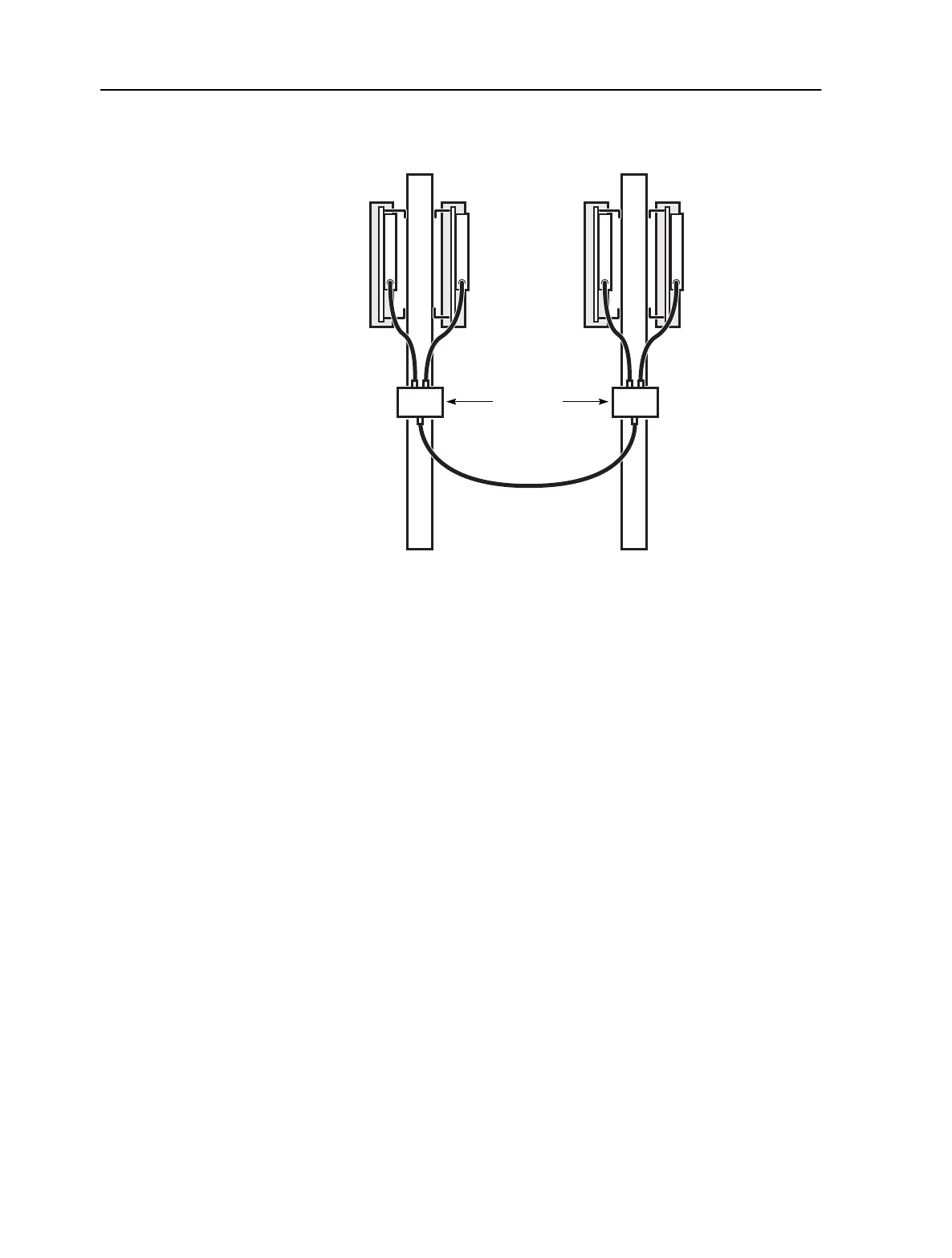
MainStreet Broadband Wireless Technical Practices 9. BTS cable connections
NNP 95-4882-01-00-A Issue 1, April 1999
9-11
DRAFT
Figure 9-3: Reference cables for redundant OTU/ORU configurations
Connecting synchronization reference cables (simplex OTU/ORU)
1. Measure and cut a length of cable that runs between the OTU and ORU,
including the distance required to run up each pole to the OTU and ORU
connectors.
2. Install N(M) connectors on each end of the cable.
3. Run the cable between the OTU and ORU.
4. Connect the cable connectors to the 100 MHz reference connectors on the OTU
and ORU.
5. Secure the cable to the pole every 1 m (3 ft) with plastic ties.
Connecting synchronization reference cables (redundant OTU/ORU)
1. Using a metal hose clamp, attach a 2:1 Combiner/Splitter to the OTU pole, just
beneath the OTU/R-OTU pair.
2. Using a metal hose clamp, attach a 2:1 Combiner/Splitter to the ORU pole, just
beneath the ORU/R-ORU pair.
3. Measure and cut four lengths of cable that are long enough to run from the 2:1
Combiner/Splitter to each of the OTUs or ORUs mounted above the 2:1
combiner splitter.
4. Install N(M) connectors on each of the lengths of cable.
13102
OTU R-OTU
BTS 2:1
Combiner/
Splitters
Synchronization
reference cable
ORU R-ORU

9. BTS cable connections MainStreet Broadband Wireless Technical Practices
Issue 1, April 1999 NNP 95-4882-01-00-A
9-12
DRAFT
5. Connect the cable connectors to the OTUs and ORUs as shown in Figure 9-3.
6. Measure and cut a length of cable long enough to run between the OTU/R-OTU
2:1 Combiner/Splitter and the ORU/R-ORU 2:1 Combiner/Splitter, including
the distance required to run up each pole to the 2:1 Combiner/Splitter
connectors.
7. Install N(M) connectors on each end of the cable.
8. Run the cable between the 2:1 Combiner/Splitters.
9. Connect the cable connectors to 2:1 Combiner/Splitters connectors on the OTU
and ORU, as shown in Figure 9-3.
10. Secure the cable to the pole with plastic ties every 1 m (3 ft).
9.4 Connecting the RS-422 cables
In a simplex OTU/ORU system, RS-422 cables connect the MAU associated with the
first T-ARIC card in a T-ARIC group to the OTU and ORU.
In a redundant OTU/ORU system, additional RS-422 cables connect:
•the redundant OTU to the MAU of the configured Tx control T-ARIC card
•the redundant ORU to the MAU of the configured Rx control T-ARIC card
Each RS-422 cable is composed of two intermediate cables. Table 9-1 lists the
intermediate cables, and the connectors required to connect them between the MAU
and the OTU/ORU.
To connect a BTS RS-422 cable
For each OTU and ORU:
1. Determine the cable length required for the distance between the OTU/ORU
and the T-ARIC card MAU.
2. Secure the cable to the pole or tower with cable ties, leaving enough length to
connect the cables to the elevated OTU or ORU positions.
3. Feed the cable through the weatherproof access panel to the grounded entry
point where the RS-422 lightning arrester is installed. Secure the cables to the
grounded entry point with cable ties, and continue to feed the cables to the
location of the MAU.
4. Secure the end of the cable to a location near the MAU with cable ties, after
ensuring that the cable is long enough to connect to the MAU connector.
5. At the grounded entry point, cut each cable to a length sufficient to allow both
ends of the cable to connect to the RS-422 lightning arresters.

MainStreet Broadband Wireless Technical Practices 9. BTS cable connections
NNP 95-4882-01-00-A Issue 1, April 1999
9-13
DRAFT
6. Install the RJ45 connectors on the cables, and connect:
• the cable from the OTU or ORU to the lightning arrester EQUIP connector
•the cable to the MAU to the lightning arrester LINE connector
7. At the OTU or ORU, install a LEMO connector on the end of the cable, and
connect the cable to the RS-422 data connector on the OTU or ORU. Use Table
9-11 to connect the LEMO connector pins and signals to the RJ45 connector pins
and signals.
Table 9-11: LEMO to RS-422 connector pins and signals
8. At the MAU, install an RJ45 connector on the end of the broadband cable, and
connect the cable to the appropriate MAU connector (OTU cable to MAU OTU
connector, ORU cable to ORU MAU connector).
9.5 Connecting SMA cables
T-ARIC cards are connected to 12:2 Combiner/Splitters by pairs of SMA cables. If
multiple T-ARIC cards are used, multiple pairs of SMA cables are used.
Note
The number of T-ARIC cards connected to the 12:2 Combiner/Splitters may be
limited by the ORU/OTU hardware. Consult Newbridge for the maximum number
of T-ARIC cards that can be connected to an OTU/ORU through a 12:2
Combiner/Splitter.
1. Connect the SMA(M) connector on the SMA cable to the Tx connector on the
T-ARIC card faceplate.
2. Connect the N(M) connector on the same SMA cable to connector 1 on the Tx
Combiner/Splitter.
3. Connect the SMA(M) connector on the SMA cable to the Rx connector on the
T-ARIC card faceplate.
4. Connect the N(M) connector on the same SMA cable to connector 1 on the Rx
Combiner/Splitter.
LEMO pin RJ45 pin Function
12Tx+
27Rx+
31Tx-
48Rx-
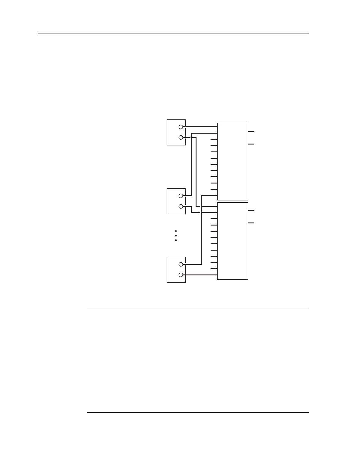
9. BTS cable connections MainStreet Broadband Wireless Technical Practices
Issue 1, April 1999 NNP 95-4882-01-00-A
9-14
DRAFT
5. Connect the Tx and Rx connectors from the other T-ARIC cards (cards 2
through 12) to Tx and Rx Combiner/Splitter connectors 2 to 12, as indicated in
Figure 9-4.
6. Install 50 Ω terminators on all unused 12:2 Combiner/Splitter connectors.
Figure 9-4: SMA cable connections
9.6 Connecting the Bias-T power cable
The Bias-T power cable connects between the Bias-T surge protector and the -48 V
power supply.
1. Connect the Bias-T power cable BNC(M) connector to the surge protector.
2. On the Bias-T power cable, connect the lug connector on the red wire to the
-48 V power supply -48 V connector, and connect the lug connector on the black
wire to the power supply 0VR connector.
13100
T-ARIC 1
Tx 12:2
Combiner/Splitter
Rx 12:2
Combiner/Splitter
1
2
3
4
5
6
7
8
9
10
11
12
1
2
3
4
5
6
7
8
9
10
11
12
Rx
Tx
T-ARIC 2 Tx
Rx
T-ARIC 12 Tx
Rx
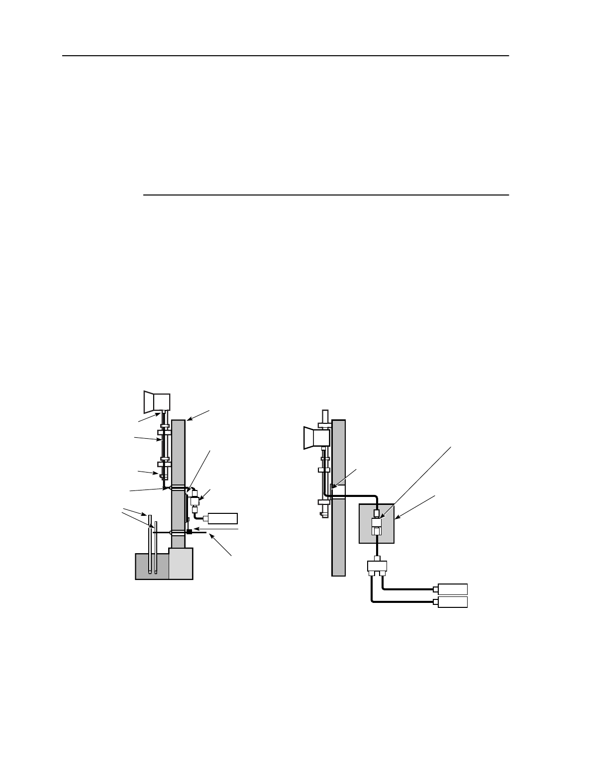
MainStreet Broadband Wireless Technical Practices 10. Installing the customer premises equipment
NNP 95-4882-01-00-A Issue 1, April 1999
10-1
DRAFT
10. Installing the customer premises
equipment
This chapter provides an overview on how to install the customer premises
equipment.
10.1 Customer premises equipment
The combined transmitter and receiver functions are provided by the OTRU. Similar
to the OTU and ORU, the OTRU is designed to be installed on an antenna mast or
building roof top at the subscriber site. If two OTRUs are installed at the same
customer site, they must be installed 1 m (3 ft) apart (horizontal or vertical), to avoid
blocking line-of-sight access to the BTS. Figure 10-1 shows typical single NIU and
dual NIU equipment.
Figure 10-1: CPE overview
OTRU
OTRU
Coaxial cables to
OTRU F connector
OTRU mast
ground connection
Weatherproof
caulk
Ground
rod(s) NIU
Lightning
arrester
with mounting
bracket
Copper
plate
Exterior
wall
Power utility
entrance ground
wire
NIU 1
NIU 2
Copper plate
(connected to
120 V ac
safety ground
i.e. NIU
ground/power
utility entrance
ground)
Lightning
arrester
with mounting
bracket
Weatherproof
access
panel
2:1
Bond
12727
Single NIU Dual NIU

10. Installing the customer premises equipment MainStreet Broadband Wireless Technical Practices
Issue 1, April 1999 NNP 95-4882-01-00-A
10-2
DRAFT
Cable loss
The CPE passive components, in all installations, are designed to provide a fixed
common loss. The losses are:
•downstream: maximum 16 dB at 2050 MHz
•upstream: 8 ±1 dB at 700 MHz
If the total loss of the installed passive components falls short of these values, do not
insert attenuators to make up the difference. Use a specific cable length to make up
the loss.
Passive components
Passive components for the CPE consist of a single coaxial cable from the NIU to the
OTRU. Figure 10-2 shows a typical single NIU and dual NIU passive component
configuration. Power for the radio is duplexed onto the line by the NIU; hence, no
external power supply is required.
Properly grounded lightning arresters are highly recommended at the building
entry point. Every customer site is different. Therefore, cable runs on the inside and
outside of the premises will vary from site to site. As with the BTS, Newbridge can
recommend the cable type and specifications for customers wishing to optimize
their CPE sites by running their own cable. Because there are many factors
associated with choosing a suitable coaxial cable, customers will be advised by
Newbridge of the manufacturers and manufacturers part numbers recommended
for these cable assemblies.
To interconnect two NIUs to one CPE OTRU, a 2:1 Combiner/Splitter is required.
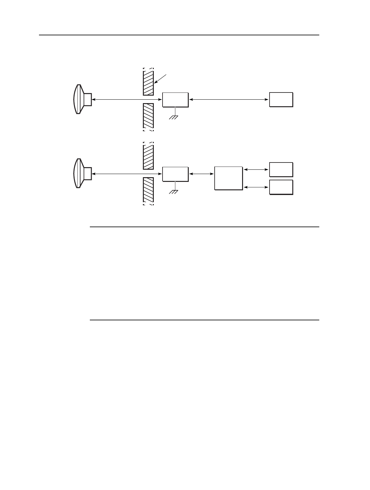
MainStreet Broadband Wireless Technical Practices 10. Installing the customer premises equipment
NNP 95-4882-01-00-A Issue 1, April 1999
10-3
DRAFT
Figure 10-2: Passive component interconnections
10.2 CPE installation tasks
Perform the following installation tasks to install the CPE:
•attach the OTRU to the pole assembly
•install the lightning arresters
•connect the CPE cables
OTRU
Exterior
wall
NIU 1
NIU
NIU 2
Lightning
arrester
OTRU
2:1
Combiner/
Splitter
Single
NIU
Dual
NIU
13056
Lightning
arrester


MainStreet Broadband Wireless Technical Practices 11. Installing the CPE OTRU
NNP 95-4882-01-00-A Issue 1, April 1999
11-1
DRAFT
11. Installing the CPE OTRU
This chapter describes how to install the back-mount or side-mount OTRU on a pole.
Note
There are two types of OTRU transceivers: side-mount and back-mount. Both
OTRUs have the same part number, and are shipped according to availability.
11.1 Mounting the OTRUs
1. Assemble the OTRU mounting hardware according to Figures 11-1 or 11-2. If
the backing plate is pre-installed, remove it.
2. Connect the mounting hardware to the pole.
i. Position the mounting hardware against the pole as shown in Figures 11-1
or 11-2; attach the backing plate with the four nuts.
ii. Secure the mounting hardware to the pole by tightening the four backing
plate bolts until the mounting hardware does not rotate freely by hand.
3. Connect the OTRU to the mounting hardware.
i. Align the OTRU as shown in Figures 11-1 or 11-2. Make sure that the
polarization indicator arrow on the rim of the OTRU antenna points
sideways for horizontal polarization installations, or that the polarization
indicator arrow on the rim of the OTRU antenna points down for vertical
polarization installations.
ii. Insert and tighten the four bolts that attach the OTRU to the mounting
hardware.
4. Install the provided plug into the drain hole on the side of the OTRU antenna
housing. Ensure that the second drain hole (located at the bottom of the OTRU
antenna housing) is clear of obstructions.
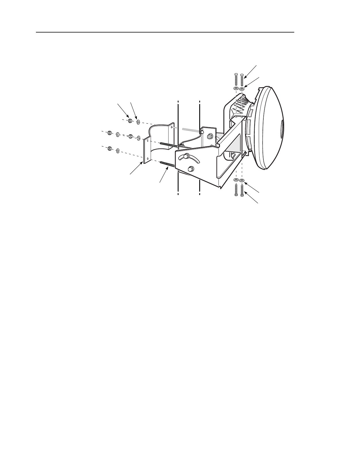
11. Installing the CPE OTRU MainStreet Broadband Wireless Technical Practices
Issue 1, April 1999 NNP 95-4882-01-00-A
11-2
DRAFT
Figure 11-1: Side-mount OTRU
12974
Backing
plate
Washer
Nut
Bolt
Washer
Bolts
(two per side)
Bolt
Washer
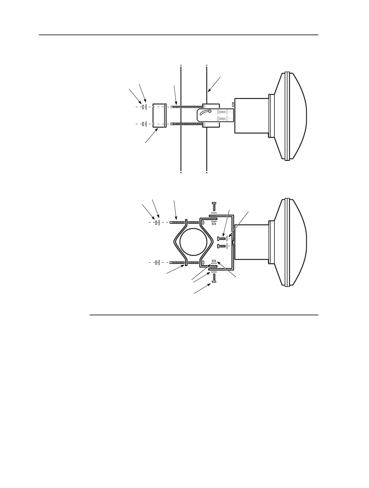
MainStreet Broadband Wireless Technical Practices 11. Installing the CPE OTRU
NNP 95-4882-01-00-A Issue 1, April 1999
11-3
DRAFT
Figure 11-2: Back-mount OTRU
Washer Bolt
Washer
Bolt
OTRU
case
OTRU
case
Bolt
Backing
plate
Backing
plate Nut
Washers
Bolt
Pole
Pole
Nut
13116
Washer
Nut
Side view
Top view

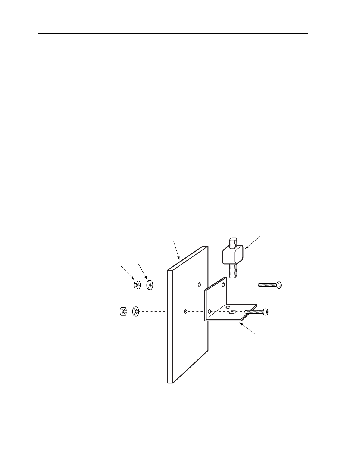
MainStreet Broadband Wireless Technical Practices 12. Installing CPE lightning arresters
NNP 95-4882-01-00-A Issue 1, April 1999
12-1
DRAFT
12. Installing CPE lightning arresters
This chapter describes how to connect CPE lightning arresters to a grounded entry
point. To correctly install a lightning arrester:
•connect the mounting bracket to the CPE grounding plate
•install the lightning arresters in the mounting brackets
12.1 Connecting the mounting bracket and lightning arrester to
the CPE grounding plate
Lightning arresters must be secured to a copper CPE grounding plate using
mounting brackets. Connect the mounting brackets and lightning arresters as shown
in Figure 12-1.
Figure 12-1: Connecting the mounting brackets to the grounding plate
Figure 12-2 shows a lightning arrester installed on a grounding plate, and connected
to broadband cables.
13108
Washer
Type F
lightning
arrester
Mounting
bracket
Copper
grounding plate
Nut
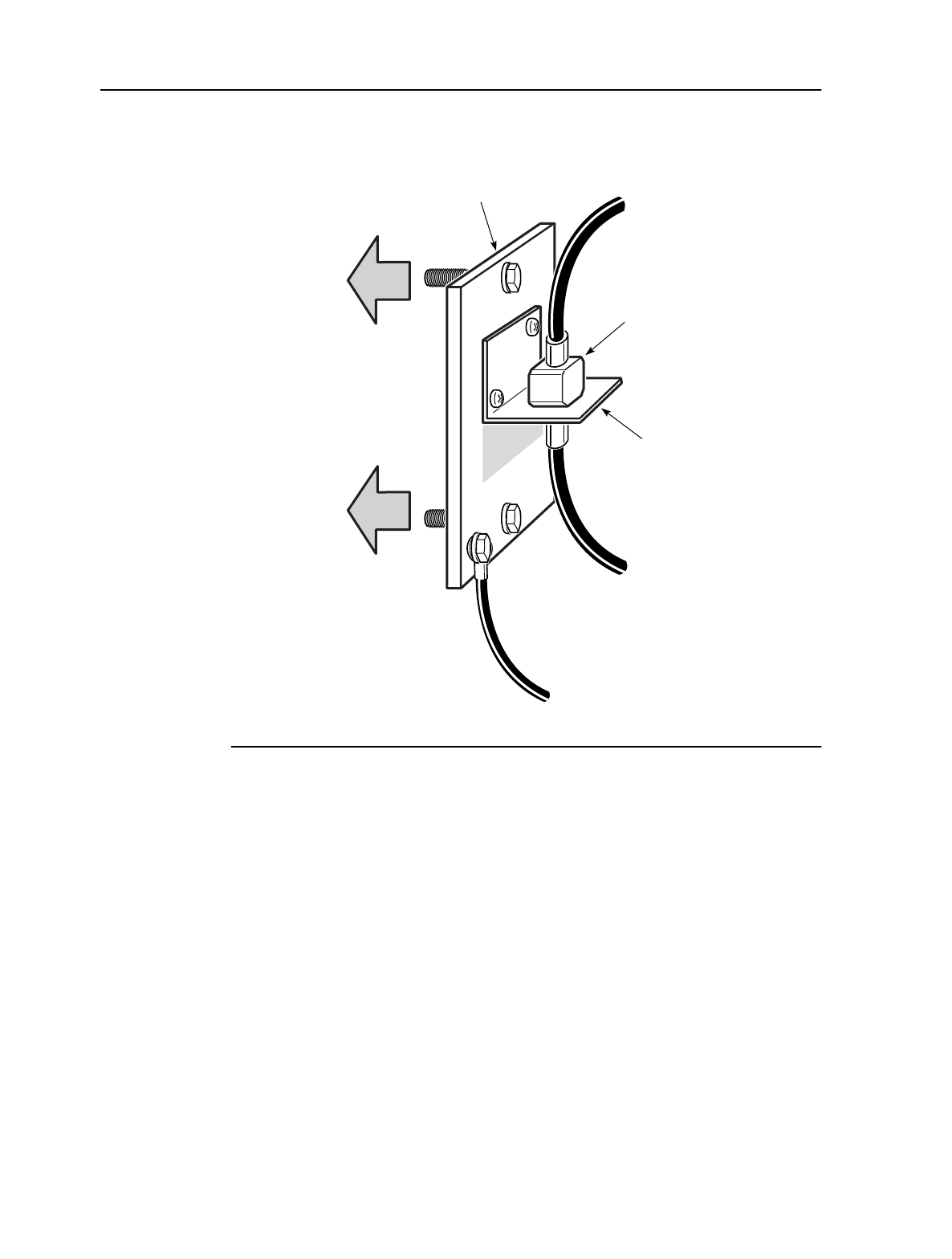
12. Installing CPE lightning arresters MainStreet Broadband Wireless Technical Practices
Issue 1, April 1999 NNP 95-4882-01-00-A
12-2
DRAFT
Figure 12-2: Connected lightning arrester
13101
CPE type F
lightning
arrester
Mounting
bracket
Safety
ground
Copper
grounding plate To NIU or 2:1
Combiner/
Splitter
To OTRU
To wall
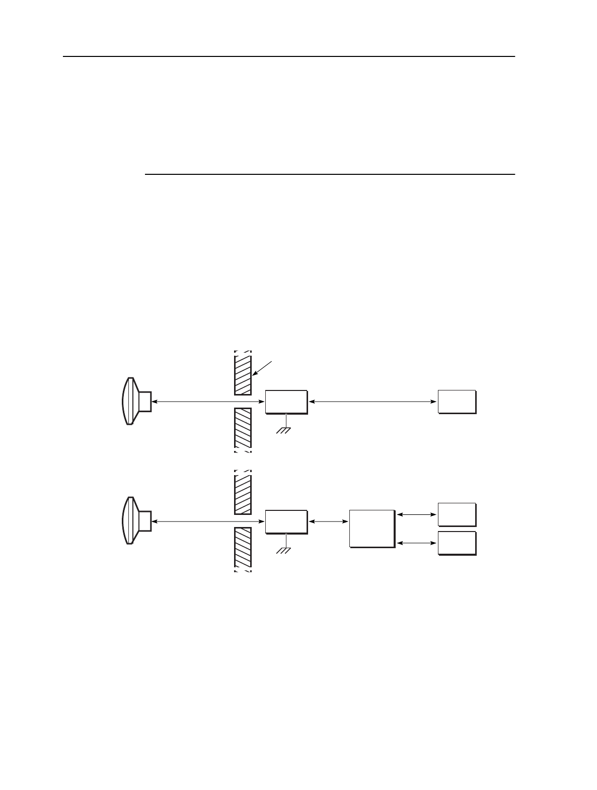
MainStreet Broadband Wireless Technical Practices 13. CPE cable connections
NNP 95-4882-01-00-A Issue 1, April 1999
13-65
DRAFT
13. CPE cable connections
This procedure describes how to select cable types, and how to connect RG-11 cables
between the CPE components.
13.1 OTRU configurations
The CPE RG-11 cable connects the OTRU transceiver to either one or two NIUs at the
customer premises. A configuration using one NIU is called a single NIU
configuration. A configuration using two NIUs is called a dual NIU configuration.
Figure 13-1 shows an example of single and dual NIU configurations. Table 13-1 lists
and describes CPE cables and connectors.
Figure 13-1: CPE single and dual NIU configurations
OTRU
Exterior
wall
NIU 1
NIU
NIU 2
Lightning
arrester
OTRU
2:1
Combiner/
Splitter
Single
NIU
Dual
NIU
13056
Lightning
arrester
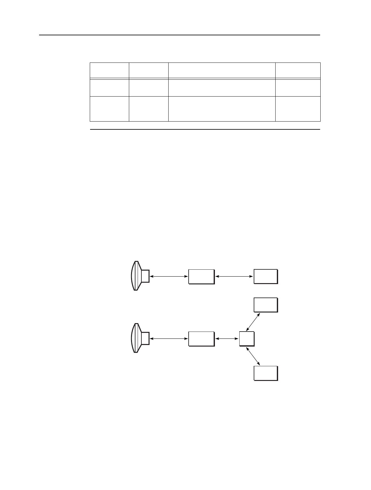
13. CPE cable connections MainStreet Broadband Wireless Technical Practices
Issue 1, April 1999 NNP 95-4882-01-00-A
13-66
DRAFT
Table 13-1: CPE cables
13.2 Decibel loss calculations
The CPE cable, connectors and equipment must provide a fixed decibel loss in both
the upstream and downstream directions. The downstream losses must not exceed
16 dB at 2050 MHz. The upstream losses must total 8 dB at 700 MHz, ± 1dB. If the
total loss does not equal the recommended values, reduce or increase cable length
accordingly.
Single and dual NIU configurations require different cable lengths to achieve the
desired cable loss. Figure 13-2 shows the cable lengths used in single and dual NIU
configurations.
Figure 13-2: Single and dual NIU cable lengths
Table 13-2 shows the loss characteristics of the single NIU components and the cable
length (65 m [213 ft]) required to achieve the fixed decibel losses.
NIU
configuration Physical path Intermediate cables Connectors
Single NIU OTRU to NIU OTRU to lightning arrester
Lightning arrester to NIU
F(M) - F(M)
F(M) - F(M)
Dual NIU OTRU to NIU OTRU to lightning arrester
Lightning arrester to 2:1 Combiner/Splitter
2:1 Combiner/Splitter to each NIU
F(M) - F(M)
F(M) - F(M)
F(M) - F(M)
OTRU
NIU
NIU 1
NIU 2
Lightning
arrester
Single NIU
Dual NIU
13099
xy
z
z
Lightning
arrester
xy
x + y + z = 30 m
x + y = 65 m
(= 213 ft)
(= 98 ft)
OTRU

MainStreet Broadband Wireless Technical Practices 13. CPE cable connections
NNP 95-4882-01-00-A Issue 1, April 1999
13-67
DRAFT
Table 13-2: Single NIU RG-11 cable (65 m [212 ft]) decibel loss calculations
Table 13-3 shows the loss characteristics of the dual NIU components and the cable
lengths required to achieve the required fixed decibel losses.
Table 13-3: Dual NIU RG-11 cable (30 m [98 ft]) decibel loss calculations
Single NIU
CPE
components
Max
VSWR
(
x
:1)
Downstream
loss
(2050 MHz)
(dB)
Upstream
loss
(700 MHz)
(dB)
Downstream
insertion and
coupling loss
(2050 MHz)
(dB)
Upstream
insertion
and
coupling
loss
(700 MHz)
(dB)
Downstream
VSWR
corrected
transmission
loss (2050 MHz)
(dB)
Upstream
VSWR
corrected
transmission
loss
(700 MHz)
(dB)
Surge
protector 1.40 0.200 0.200 0.20 0.20 0.21 0.21
1 × RG-11
cable
(65 m [212 ft])
1.20 0.150 0.105 9.75 6.83 9.91 6.95
4 × F-type
connectors 1.40 0.200 0.200 0.80 0.80 0.97 0.97
Total loss — — — 10.75 7.83 11.09 8.12
Dual NIU CPE
components Max
VSWR
(
x
:1)
Downstream
loss
(2050 MHz)
(dB)
Upstream
loss
(700 MHz)
(dB)
Downstream
insertion and
coupling loss
(2050 MHz)
(dB)
Upstream
insertion
and
coupling
loss
(700 MHz)
(dB)
Downstream
VSWR
corrected
transmission
loss (2050 MHz)
(dB)
Upstream
VSWR
corrected
transmission
loss
(700 MHz)
(dB)
1 × RG-11
jumper 1.20 0.150 0.105 0.00 0.00 0.00 0.00
1 × 2:1
Combiner/
Splitter
1.200 0.500 0.000 0.00 0.00 0.00 0.00
1 × surge
protector 1.40 0.200 0.200 0.20 0.20 0.21 0.21
1 × RG-11
cable
(30 m [98 ft])
1.20 0.150 0.105 4.50 3.15 4.58 3.21
6 × F-type
connectors 1.40 0.200 0.200 1.20 1.20 1.61 1.61
Total loss — — — 9.05 7.66 10.75 8.64

13. CPE cable connections MainStreet Broadband Wireless Technical Practices
Issue 1, April 1999 NNP 95-4882-01-00-A
13-68
DRAFT
13.3 Connecting single NIU cables
1. Cut a 65 m (212 ft) length of RG-11 cable into two lengths, as follows.
•The first length must be long enough to run from the OTRU F(F) connector
to the lightning arrester.
•The second length must be long enough to run from the lightning arrester to
the NIU IF In/Out and 35 VDC Out connector.
2. Install F(M) connectors on the ends of both cables.
3. Connect the first length of cable between the OTRU F(J) connector and one of
the lightning arrester connectors.
4. Connect the second length of cable between the second lightning arrester
connector and the NIU IF Input/Output and 35 VDC connector.
5. If the cable run between the OTRU and the NIU is less than 65 m (212 ft), one or
both of the two lengths of cable will be longer than is necessary to reach
between the connected devices. Do not cut off this extra cable length. If
necessary, coil the cable and put the cable in an area that does not impede access
to any CPE components.
13.4 Connecting dual NIU cables
Note
The total cable length between the OTRU and an NIU must be 30 m (98 ft).
1. Cut a 30 m (98 ft) length of RG-11 cable into three lengths, as follows.
•The first length must be long enough to run between the OTRU and the
lightning arrester.
•The second length must be long enough to run between the lightning
arrester and the 2:1 Combiner/Splitter.
•The third length of cable must be long enough to run between the 2:1
Combiner/Splitter and the NIU that is farthest (in terms of the length of
cable required) from the 2:1 Combiner/Splitter.
2. Cut a fourth length of cable equal in length to the third length of cable.
3. Install F(M) connectors on all the cable ends.
4. Connect the first length of cable between the OTRU F(F) connector and one of
the lightning arrester connectors.
5. Connect the second length of cable between the second lightning arrester
connector and the 2:1 Combiner/Splitter IN connector.

MainStreet Broadband Wireless Technical Practices 13. CPE cable connections
NNP 95-4882-01-00-A Issue 1, April 1999
13-69
DRAFT
6. Connect the third length of cable between either of the remaining 2:1
Combiner/Splitter connectors and the IF In/Out and 35 VDC Out connector on
the first NIU.
7. Connect the fourth length of cable between the remaining 2:1
Combiner/Splitter connector and the IF Input/Output and 35 VDC connector
on the second NIU.
8. If the cable run between the OTRU and either NIU is less than 30 m (98 ft), one
or more of the lengths of cable will be longer than is necessary to reach between
the connected devices. Do not cut off this extra cable length. If necessary, coil
the cable and put the cable in an area that does not impede access to any CPE
components.


MainStreet Broadband Wireless Technical Practices 14. OTRU alignment
NNP 95-4882-01-00-A Issue 1, April 1999
14-1
DRAFT
14. OTRU alignment
This chapter describes how to align an OTRU by adjusting the azimuth, elevation
and vertical angle of an OTRU. This procedure requires a minimum distance of 300
m (900 ft) between the BTS and the OTRU. If the distance is less, contact Newbridge
for information.
14.1 Test equipment and parts
A spectrum analyzer or power meter is required for this procedure.
Table 14-1 lists the components and cables required to align the OTRU.
Table 14-1: Components and cables required
Equipment Supplier
Bias-T Newbridge (part number 90-6516-01)
Pulsar (BT-D6-411NM)
F(F) to N(M) adapter Gilbert Engineering (NS-2873-1)
BNC(M) to F(F) adapter Gilbert Engineering (G-BNCF-MF)
N(F) to N(F) adapter Narda Model 77
RF cable, F(M), 1 m (3 ft) in
length minimum any
RF cable, N(M), 1 m (3 ft) in
length minimum any
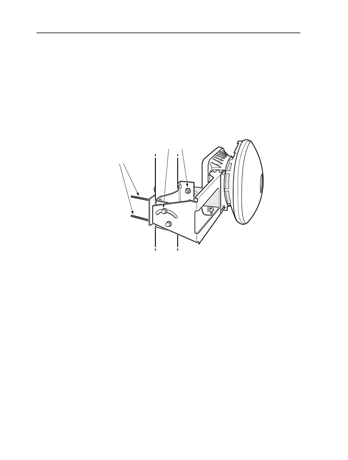
14. OTRU alignment MainStreet Broadband Wireless Technical Practices
Issue 1, April 1999 NNP 95-4882-01-00-A
14-2
DRAFT
14.2 Aligning the OTRU
An OTRU must be aligned to point directly toward the BTS in order to receive a
reliable signal. Figure 14-1 shows the mounting hardware bolts used to adjust the
azimuth, elevation and vertical angle of an OTRU in relation to the BTS.
In order to align the OTRU to the BTS signal, adjust the OTRU mounting hardware
to find a position that provides the highest possible power readings. Acceptable
peak power readings are based on RF planning and analysis activities that should be
done before an OTRU is installed.
Figure 14-1: OTRU alignment adjustment hardware
1. Switch off the NIU, and connect the test equipment as shown in Figure 14-2.
Elevation
and azimuth
adjustment
bolts
12973
Vertical angle
adjustment
bolts
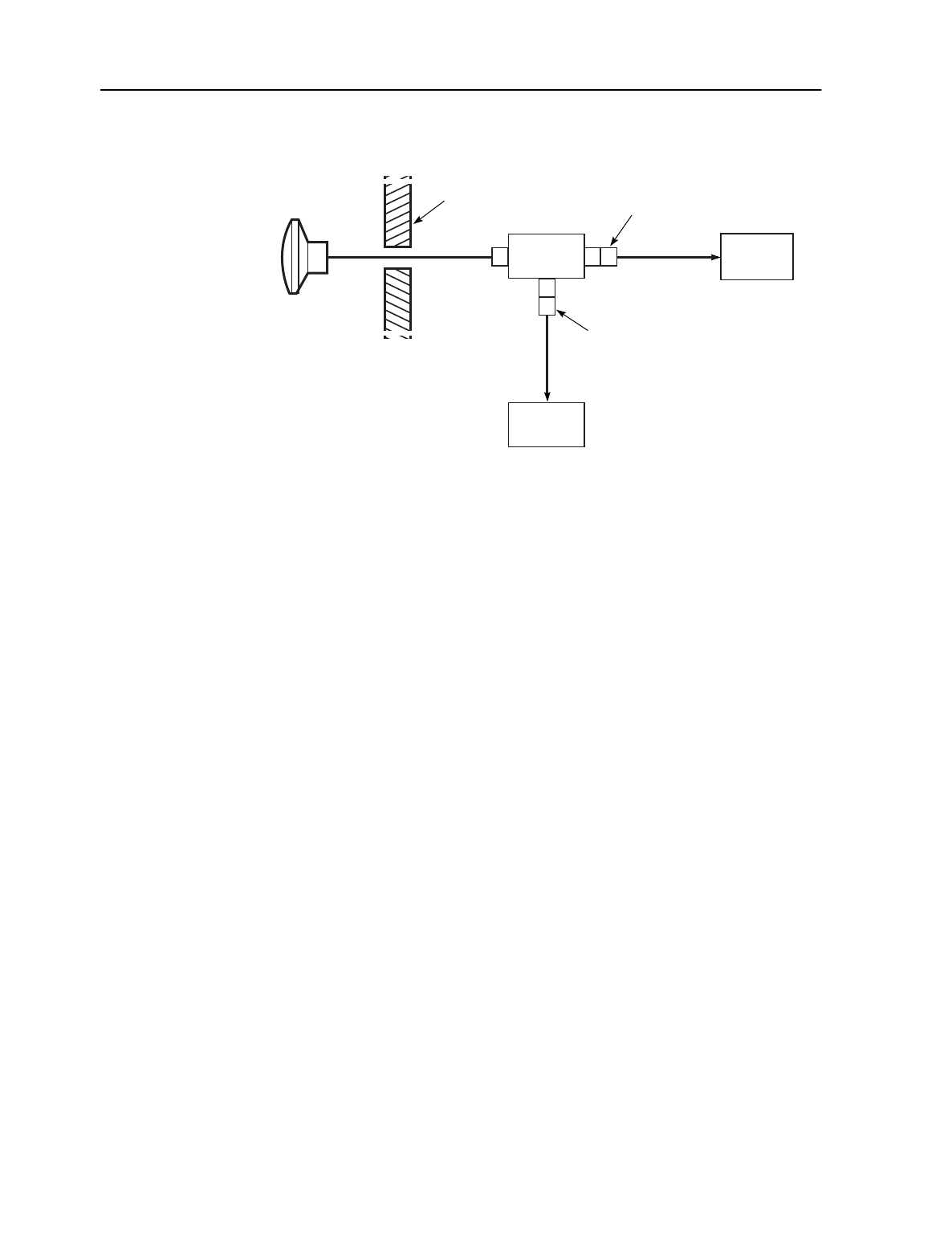
MainStreet Broadband Wireless Technical Practices 14. OTRU alignment
NNP 95-4882-01-00-A Issue 1, April 1999
14-3
DRAFT
Figure 14-2: Test equipment configuration
CPE
OTRU
13089
Test
equipment
Bias-T
DC OUT
N(F) to N(F)
adapter
RF IN
BNC male to
F(F) adapter
IF
cable
F(M)
DC IN
NIU
Exterior
wall

2. Ensure that the BTS is transmitting a signal in the CPE sector.
3. Adjust the bolts identified in Figure 14-1 until the OTRU mounting hardware is
sufficiently snug to hold the unit on the mast, but is loose enough to allow easy
rotation of the unit by hand. Set the azimuth, elevation and rotation of the
antenna to point at the approximate location of the BTS.
4. Switch the NIU on.
5. Prepare the test equipment to make the measurements.
a. If measurements are made using a power meter, set AVERAGING to a low
figure (for example, 2).
b. If a spectrum analyzer is used, set CENTER FREQUENCY to a value that
is 200 MHz higher than the tone frequency at the BTS, and set
BANDWIDTH to 100 MHz.
6. Observe and record the measurement on the test equipment, and adjust the
azimuth of the OTRU to provide a peak power reading.
7. Observe and record the measurement on the test equipment, and adjust the
elevation of the OTRU to provide a peak reading.
8. Observe and record the measurement on the test equipment, and adjust the
vertical angle of the OTRU to provide a peak reading.
9. Tighten the mounting hardware and verify the measurements previously made
to ensure that the OTRU is still aligned to provide a peak reading on the test
equipment.
10. Switch the NIU off, disconnect the test equipment and reconnect the outdoor
cable to the OTRU. Switch the NIU on.

MainStreet Broadband Wireless Technical Practices 15. Node management
NNP 95-4882-01-00-A Issue 1, April 1999
15-1
DRAFT
15. Node management
This chapter describes:
•node management through the NMTI
•the main menu
15.1 Node management overview
NMTI user interface
The NMTI is a user-interface software program that resides in the PROM module on
the NIUs and the MainStreetXpress 36170 Control card. It allows you to have a node
management session through an attached ASCII (VT100-compatible) terminal.
The 28110 and 28120 MainStreet NIUs have their own NMTIs, which are used to set
up, operate, monitor and maintain the NIUs.
Although the T-ARIC card does not have its own NMTI, it can be configured
through an NMTI session with the MainStreetXpress 36170 Control card.
For information on initiating a node management session with the MainStreetXpress
36170 Control card, see the MainStreetXpress 36170 Technical Practices. For
information on softkey conventions used in this manual, see “Softkeys” in
section 15.2.
To initiate a node management session with an NIU
The following steps describe the logon procedure for the first NMTI session. Users
logging on later may find that some steps are not necessary, are slightly different or
are skipped because previous users have changed the configuration. If the node
management equipment is used regularly, steps 1 to 3 may not be necessary.
1. Switch on the NIU. The power switch is on the back panel.
The LED display runs through a predetermined pattern, while self-diagnostics
are performed.
2. Ensure the terminal is connected to the front panel serial port of the NIU and
switch on the terminal.

15. Node management MainStreet Broadband Wireless Technical Practices
Issue 1, April 1999 NNP 95-4882-01-00-A
15-2
DRAFT
3. Verify that the terminal is set up for the following:
•eight data bits
•one stop bit
•no parity
•no local echo
•baud rate of 9600 b/s
4. Press the ↵ key on the terminal at approximately one second intervals until a
startup message appears on the terminal, and you are prompted for an access
level.
5. Enter your access level number.
a. If this is the first NMTI session, enter a <5> and press ↵. Level 5 users have
read and write access to all areas required to configure the system.
b. If this is not the first NMTI session and you have been assigned an access
level (between 0 and 5), enter your level number and press ↵.
The NMTI prompts you for the password (unless you enter an access level
of 0, which allows read-only access). The default password is
<mainstreet>.
6. If you are not a level 0 user, enter the password.
a. If this is the first NMTI session, type <mainstreet> (lower case) and press
↵. The default password for all levels is <mainstreet> and is not displayed
on the screen.
b. If this is not the first NMTI session, enter the password assigned to your
access level.
The NMTI displays the main menu screen, as shown in Figure 15-1.

MainStreet Broadband Wireless Technical Practices 15. Node management
NNP 95-4882-01-00-A Issue 1, April 1999
15-3
DRAFT
Figure 15-1: NIU Main Menu Screen
Setting the password and level zero
When you initiate a node management session you can change your password and
enable or disable level 0 access. In the following softkey menus, an asterisk (*)
indicates the default setting.
To change the password
To enable or disable level zero access
HOUSE — LEVEL_0/NO_LEVEL_0*
28110 T1 NIU AA1211-R0-AF NIU_5:?:? MAJ:Alrm:1 03-JAN-1999 12:56
1-CONFIG 2-HOUSE 3-MAINT 4-STATISTICS 5-ALARMS
6- 7- 8- 9-QUIT 0-
LEVEL_1 LEVEL_2 LEVEL_3 LEVEL_4 LEVEL_5*
HOUSE — CHNG_PSSWD <level_5_password> ↵
SK000231

15. Node management MainStreet Broadband Wireless Technical Practices
Issue 1, April 1999 NNP 95-4882-01-00-A
15-4
DRAFT
Screen display
The NMTI screen display has 24 lines; each line is 78 characters wide. The screen is
arranged in the following five functional areas, which are described in Table 15-1:
•header line
•data area
•command line
•diagnostics line
•softkey area
The screen refreshes when you select softkeys or make keyboard entries.
Table 15-1: Description of NMTI screen areas
Note
1. “01-JAN-1970” appears in the header line until the BTS sends the date.
Area Description
Header line Specifies:
• product name
• software generic and revision number
• node name (a blank space if a node name has not been assigned)
• the number of alarms in the major alarm queue
• date (1)
• time
Data area Occupies 18 lines
Displays information associated with the current menu
Command line Displays the softkey selections and keyboard entries as they are entered
Diagnostics line Displays:
•prompts
•warnings
•error messages
•valid ranges for numeric parameters
•NIU ID number
Softkey area Occupies the bottom two lines of the screen
Line 1 indicates the softkeys associated with keyboard keys 1 through 5
Line 2 indicates the softkeys associated with keyboard keys 6 through 0

MainStreet Broadband Wireless Technical Practices 15. Node management
NNP 95-4882-01-00-A Issue 1, April 1999
15-5
DRAFT
15.2 Main menu
The group of softkeys that first appears when you log on to an NIU is called the main
menu (see Figure 15-1) and provides access to the following main functions:
•CONFIG
•HOUSE
•MAINT
•STATISTICS
•ALARMS
Table 15-2 lists the functions of each main menu softkey.
Table 15-2: Description of main menu softkeys
Softkeys
The term softkey means both a numbered key (on the keyboard) and the function
associated with it. The softkey area shows each available keyboard key and its
current function. Functions change each time a softkey is selected.
Table 15-3 shows the softkey conventions used in this manual.
Main menu softkey function
CONFIG Configuring system parameters
Defining connections
HOUSE Specifying the node name
Configuring the system serial ports
Defining the parameters for access to the NMTI
MAINT Performing system diagnostics
Monitoring status
Performing loopbacks
STATISTICS Monitoring and clearing use and performance statistics
Setting refresh modes
ALARMS Monitoring the system for abnormal conditions and significant events
continuously and listing them in queues that can be viewed and edited
Assigning a classification to each alarm type
Selecting the method of logging alarms

15. Node management MainStreet Broadband Wireless Technical Practices
Issue 1, April 1999 NNP 95-4882-01-00-A
15-6
DRAFT
Table 15-3: Softkey conventions
Selecting softkeys
Select softkeys by pressing a number key (0 through 9) on the keyboard or number
pad. For example, to select HOUSE from the main menu, press <2>. The exception
is when the NMTI prompts for a numeric entry and you want to select a display
softkey, such as CANCEL or QUIT. First press <Esc>, then press the softkey number.
If you do not press <Esc> first, the NMTI interprets your softkey selection as a
numeric entry.
Selecting a softkey updates the data area, changes the softkey selection or adds text
to the command line.
Most softkeys add their function to the command line. Exceptions are MORE,
CANCEL, QUIT, PROCEED and display softkeys.
Softkey functions
Table 15-4 describes softkey functions.
Table 15-4: Softkey functions
Convention Example
Softkeys are written as they appear on the screen, in upper case. CIRCUIT
Some softkeys have underscores. NVM_DATA
Some softkeys have hyphens. END-TO-END
Some softkeys are marked with an asterisk (*) to indicate that they are default
settings. 30_MIN*
Some softkeys have an oblique, which indicates that they are toggle softkeys with
two states.The state or function that is not in effect is shown next to the softkey
number.
SHORT/LONG*
The PROCEED softkey executes an instruction; it is not included in the procedures
unless selecting it has effects in addition to executing the instruction. PROCEED
Softkey Functions Format
PREVIOUS Displays the previous screen of data, if one
exists. Always associated with the 1 key.
NEXT Displays the next screen of data, if one
exists. Always associated with the 2 key.
MORE Displays additional menu selections,
where they exist. Always associated with the 7 key.
CANCEL Cancels the last part of the instruction
being entered.
Returns to the previous menu.
Cancels the command.
Always associated with the 8 key. (1)
QUIT Logs you off the node when selected from
the main menu.
Displays the main menu when selected
from any other menu.
Always associated with the 9 key. (1)

MainStreet Broadband Wireless Technical Practices 15. Node management
NNP 95-4882-01-00-A Issue 1, April 1999
15-7
DRAFT
Notes
1. You may need to press <Esc> to access this softkey if the node management session is expecting
a text or number string.
2. PROCEED appears in the softkey area only when required: The NMTI prompts you with the
message “Press PROCEED to confirm change”. Only the CANCEL, QUIT and PROCEED softkeys
appear. If you select PROCEED, all softkeys disappear briefly and a message indicates the
instruction is being executed. Then the softkeys for the next operation appear.
Note
Some softkeys described in this manual may not appear on your screen. The softkeys
available depend on your access level, the system configuration, and the software
generic you are using.
Keyboard entries
Use the keyboard to type text or number strings when the NMTI prompts you for an
entry.
Examples of keyboard entries are:
•passwords
•node names
•dates
•alarm numbers
The display indicates that the node management session expects a keyboard entry
by:
•displaying “??-??” or “...” on the command line
•displaying a prompt on the diagnostics line
•removing all softkeys except CANCEL, QUIT and display softkeys
In many cases, the diagnostics line prompts you for a valid range or required entry
format. If the format includes a hyphen (-) or a slash (/), it must be typed as part of
the entry.
PROCEED (2) Executes the instruction. Always associated with the 0 key. (1)
Softkey Functions Format

15. Node management MainStreet Broadband Wireless Technical Practices
Issue 1, April 1999 NNP 95-4882-01-00-A
15-8
DRAFT
Keyboard conventions
Some keys are assigned names, for example, Return and Esc. Table 15-5 shows
keyboard entry conventions used in this manual.
Table 15-5: Keyboard entry conventions
Keyboard entry formats
Keyboard entries require specific formats and appear on the diagnostics line. The
format can be a mixture of specific letters and variable information, for example:
<CGgroup>
In this example, CG must be typed and group represents variable information.
Keyboard entry functions
Table 15-6 shows the functions associated with keyboard entries.
Table 15-6: Keyboard entry functions
Convention Example
Keyboard entries are indicated by italicized text enclosed in angle
brackets <
shelf-slot
>
A key with a name is indicated by the name of the key with the first letter
capitalized, and enclosed by angle brackets <Esc>
The Return key appears in the procedures where required, because the
display does not prompt for it ↵
Key(s) Function
↵ Completes and executes a keyboard entry.
<Esc> <R> Refreshes the screen in the following situations:
•when a database verification is in progress
•when monitoring system alarms to update the displayed information
•when a transmission error or some other event corrupts the
displayed information
•when monitoring statistics to update displayed information
<Delete> or <Backspace> Deletes a keyboard error.
<Esc> <
softkey number
> Lets you select a softkey when the node management session expects
a number or text string keyboard entry.

MainStreet Broadband Wireless Technical Practices 16. Restrictions of Release 1.1
NNP 95-4882-01-00-A Issue 1, April 1999
16-1
DRAFT
16. Restrictions of Release 1.1
This chapter describes the software and hardware restrictions of the MainStreet
Broadband Wireless system.
16.1 BTS restrictions
Table 16-1 lists the BTS restrictions.
Table 16-1: BTS restrictions
Name Limit Level
CPSS links 300 System
Downlink timeslots per port 350 (at 18 MHz)
700 (at 36 MHz)
T-ARIC card
NIUs (E1 per port, fully configured without cell padding) 8 T-ARIC card
Managed NIUs per BTS 299 NIU
NIUs per BTS 3300 NIU
NIUs per port 300 T-ARIC card
NIUs (T1 per port, fully configured without cell padding) 10 T-ARIC card
T-ARIC card ports per BTS 94 T-ARIC card
Uplink timeslots per port 266 T-ARIC card

16. Restrictions of Release 1.1 MainStreet Broadband Wireless Technical Practices
Issue 1, April 1999 NNP 95-4882-01-00-A
16-2
DRAFT
16.2 ATM restrictions
Table 16-2 lists the ATM restrictions.
Table 16-2: ATM restrictions
Name Limit
Connections per T-ARIC port 4096
CPSS over RF Not supported
EPD (early packet discard) over RF Not supported
PPD (partial packet discard) over RF Not supported
Service categories supported CBR, UBR, VBR
VCI range 1 to 511
VPI limitations 255 - reserved
254 - reserved
253 - reserved for ATM control messaging
252 - reserved (provides date and time information to NIUs)
251 - reserved
250 - reserved
0 to 249 - used for data connections
VPIs per NIU 1 (The same VPI can be used by multiple NIUs that are using
the same T-ARIC card, providing the VCIs are unique, and
are within the acceptable range.)

MainStreet Broadband Wireless Technical Practices 17. Configurable features summary
NNP 95-4882-01-00-A Issue 1, April 1999
17-1
DRAFT
17. Configurable features summary
This chapter summarizes the configurable features for the T-ARIC card and the
NIUs.
17.1 NIU configurable options
Tables 17-1 to 17-5 describe the features, configurable options and default settings
for NIUs. The Reference column indicates where configuration information can be
found.
Table 17-1: NIU channel group features
Note
1. Can be configured on a channel, channel group or channel range.
Table 17-2: NIU SNMP features
Feature Configurable options and default Reference
Add/delete channel or range channel (or channel range) from 1 to 31
no defaults
18.1
Channel group name up to 16 characters
no default
18.1
Playout buffer 0 to 6 ms (increments of 0.5 ms)
default: 3 ms
19.1
Trunk conditioning data pattern (1) 0x00 to 0xFF, IDLE (0xEF) or SEIZED (0x1A)
default: 0xFF
18.5
Trunk conditioning signaling
pattern 1 (1)
0x00 to 0xFF
default: 0x00
18.5
Trunk conditioning signaling
pattern 2 (1) 0x00 to 0xFF
default: 0x00
18.5
User data octets per cell 1 to 46, or all
default: all
19.1
Feature Configurable options and default Reference
SNMP access privileges none, read or read/write
configurable for each of the 10 communities
default: read
20.1
SNMP community name up to 16 characters
configurable for each of the 10 communities
no default
20.1

17. Configurable features summary MainStreet Broadband Wireless Technical Practices
Issue 1, April 1999 NNP 95-4882-01-00-A
17-2
DRAFT
Table 17-3: NIU modem features
SNMP element manager IP
address xxx.xxx.xxx.xxx format
configurable for each of the 10 communities
no default
20.1
SNMP trap community name up to 16 characters
configurable for each of the 10 trap communities
no default
20.2
SNMP trap element manager IP
address xxx.xxx.xxx.xxx format
configurable for each of the 10 trap
communities
no default
20.2
SNMP trap status enabled or disabled
default: disabled
20.2
Feature Configurable options and default Reference
Add channel frequency channel frequency: 27500 to 28600 (increments
of 1 MHz)
channel bandwidth: 36 MHz
no defaults
21.10
Tx LO offset 17000 MHz to 40000 Mhz
default: 26000 MHz
21.10
Rx LO offset 17000 MHz to 40000 Mhz
default: 26000 MHz
21.10
RF band start frequency 20000 MHz to 40000 MHz
default: 27500 MHz
21.10
RF band end frequency 20000 MHz to 40000 MHz
default: 28600 MHz
21.10
IF band start frequency 950 MHz to 2050 MHz
default: 950 MHz
21.10
Channel bandwidth See Addchannel frequency 21.10
Channel frequency See Addchannel frequency 21.10
Channels (number of) See Addchannel frequency 21.10
Downlink frequency offset -320 to 320 Mhz
default: 0 Mhz
21.2
Power level (maximum) after
network entry 60 to -10 dBm
default: -10 Mhz
21.10
Power level (minimum) after
network entry 60 to -10 dBm
default: -40 MHz
21.10
Power level (maximum) before
network entry 60 to -10 dBm
default: -10 MHz
21.10
Power level (maximum) before
network entry 60 to -10 dBm
default: -40 MHz
21.10
Feature Configurable options and default Reference

MainStreet Broadband Wireless Technical Practices 17. Configurable features summary
NNP 95-4882-01-00-A Issue 1, April 1999
17-3
DRAFT
Table 17-4: 28120 MainStreet E1 NIU port features
Feature Configurable options and default Reference
AAL service type SDT_BASIC, SDT_CAS, UDT or
UDT_PERFMON
default: UDT
19.1
LOF alarm clearing 1 to 30 s (increments of 0.1 s)
default: 10 s
18.2
LOF alarm declaration 1 to 30 s (increments of 0.1 s)
default: 0.8 s
18.2
Output timing ACR, SRTS, or network
default: synchronous
18.2
Padding octet value 0 to FF
default: FF
18.2
Port name up to 15 characters
no default
18.2
CRC framing on or off
default: on
18.2
signaling 31 channel or CAS
default: CAS
18.2

17. Configurable features summary MainStreet Broadband Wireless Technical Practices
Issue 1, April 1999 NNP 95-4882-01-00-A
17-4
DRAFT
Table 17-5: 28110 MainStreet T1 NIU port features
17.2 T-ARIC configurable options
Tables 17-6 to 17-10 list the T-ARIC card features, configurable options and default
settings.
You must configure the following T-ARIC card features:
•downstream channel frequency
•downstream IF start
•group number
•Rx RF frequency upstream end
•Rx RF frequency upstream start
•Tx RF frequency downstream end
•Tx RF frequency downstream start
•upstream IF start
Feature Configurable options and default Reference
AAL service type SDT_BASIC, SDT_CAS, UDT or
UDT_PERFMON
default: UDT
19.1
CRC framing on or off
default: on
18.2
DS1 build-out 0, -7.5, -15 or -22 dB
0 dB
18.2
DSX-1 line length 0 to 132, 133 to 265, 266 to 398, 399 to 532, 533
to 654 ft
default: 0 to 132 ft
18.2
Framing SF (D4) or ESF
default: ESF
18.2
LOF alarm clearing 1 to 30 s (increments of 0.1 s)
default: 10 s
18.2
LOF alarm declaration 1 to 30 s (increments of 0.1 s)
default: 0.8 s
18.2
Output timing ACR, SRTS or network
default: network
18.2
Port name up to 15 characters
no default
18.2
Red alarm indication alarm clearing on LOF clear, or on resynch
default: on LOF clear
18.2
Zero suppression B8ZS or JB7
default: B8ZS
18.2

MainStreet Broadband Wireless Technical Practices 17. Configurable features summary
NNP 95-4882-01-00-A Issue 1, April 1999
17-5
DRAFT
Table 17-6: T-ARIC card NIU features
Table 17-7: T-ARIC card modem features
Table 17-8: T-ARIC card group features
Feature Configurable options and default Reference
NIU ID 100 to 3399
no default
21.14
NIU serial number 19 characters
no default
21.14
NIU type CE 21.14
NIU user data VPI 0 to 249
default: 0
19.2
Feature Configurable options and default Reference
Add NIU NIU ID: 100 to 3399
no default
21.13
Demodulator enabled or disabled
default: disabled
21.13
Downstream channel
frequency 20000 to 40000 MHz (in increments of 1
MHz)
no default
21.12
Timeslots reserved for NIU
contention 2 to 133 (minus the number of polling
slots minus the number of guard slots)
default: 2
21.13
Timeslots reserved for NIU
UBR connections 0 to 133 (minus the number of polling
slots minus the number of guard slots)
default: 0
21.13
Timeslots reserved for guard
slots 1 to 3
default: 2
21.13
Tx power level -22 to +8 dB (in increments of 2 dB)
default: -22 dB
21.12
Tx power level status auto enable or auto disable
default: auto disable
21.12
Upstream channel frequency 20000 to 40000 MHz (in increments of 1
MHz)
no default
21.13
Feature Configurable options and default Reference
Downstream IF start disabled, 400 to 900 MHz
(in increments of 1 MHz)
no default
21.11
Group number 1 to 64
no default
21.11
Rx control enabled or disabled
default: disabled
21.11

17. Configurable features summary MainStreet Broadband Wireless Technical Practices
Issue 1, April 1999 NNP 95-4882-01-00-A
17-6
DRAFT
Table 17-9: T-ARIC card port features
Table 17-10: T-ARIC card slot features
Rx RF upstream frequency end 20000 to 40000 MHz (in increments of 1
MHz)
no default
this parameter must be configured
21.11
Rx RF upstream frequency
start 20000 to 40000 MHz (in increments of 1
MHz)
no default
21.11
Tx control enabled or disabled
default: disabled
21.11
Tx interface power level disabled, -22 to +8 dBm (in increments of
2 dBm)
-22 dBm (the upconverter is disabled until
the Tx RF is specified for the T-ARIC
group)
21.11
Tx RF downstream frequency
end 20000 to 40000 MHz (in increments of 1
MHz)
no default
21.11
Tx RF downstream frequency
start 20000 to 40000 MHz (in increments of 1
MHz)
no default
21.11
Upstream IF start disabled, 400 to 900 MHz (in increments
of 1 MHz)
no default
21.11
Upstream IF frequency offset -500 to 0 MHz (in increments of 1 MHz)
no default
21.11
Feature Configurable options and default Reference
Downstream channel width 18 MHz
default: 18 MHz
21.12
Port name 15 characters
no default
21.15
Feature Configurable options and default Reference
Slot name 15 characters
no default
21.16
Feature Configurable options and default Reference

MainStreet Broadband Wireless Technical Practices 18. NIU TDM configuration options
NNP 95-4882-01-00-A Issue 1, April 1999
18-1
DRAFT
18. NIU TDM configuration options
This chapter describes how to configure the TDM options. The options supported by
the 28110 and 28120 MainStreet NIUs include:
•channel groups
•ports
•robbed bit signaling (forthe 28110 MainStreet T1 NIU only)
•serial ports
•trunk conditioning
18.1 Channel group configuration
Channel group configuration includes:
•adding channels to a channel group
•assigning the channel group name
•deleting channels from a channel group
Note
Channel groups can only be configured if the NIU port has an AAL service type of
SDT_BASIC or SDT_CAS.
Restrictions on channel group configuration
The following restrictions apply.
•A channel can belong to only one channel group at a time.
•A channel group must be identified by the lowest number channel that is a part
of the group. For example, CG3 must contain channel 3 and not channel 1 or
channel 2.
•Channel 31 corresponds to timeslot 16 on an E1 port; if you configure channel 31
as part of a channel group, the system treats channel 31 as though it is timeslot
16. For example, a channel group containing channels 16, 20 and 31 is identified
as CG31 because the timeslot that corresponds to channel 31 (timeslot 16) comes
before the timeslot that corresponds to channel 16 (timeslot 17) on an E1 port.

18. NIU TDM configuration options MainStreet Broadband Wireless Technical Practices
Issue 1, April 1999 NNP 95-4882-01-00-A
18-2
DRAFT
To add channels to a channel group
CONFIG — CHANNELGROUP — <CGgroup> ↵ — ADD_CHANNEL — <channel> or
<start-end> ↵
where
group is an integer from 1 to 24 for T1 NIUs, or 1 to 31 for NIUs
channel is an integer from 1 to 24 for T1 NIUs, or 1 to 31 for NIUs
start is an integer from 1 to 24 for T1 NIUs, or 1 to 31 for E1 NIUs
end is an integer from 2 to 24 for T1 NIUs, or 2 to 31 for E1 NIUs, and end must be greater than start
Note
You can add single channels and ranges of channels at the same time by separating
the channel numbers or range of channel numbers with a comma. For example, to
add channel 2, channel 4, and channels 5 to 7, enter <2,4,5-7>.
To assign a channel group name
CONFIG — CHANNELGROUP — <CGgroup> ↵ — NAME — <groupname> ↵
where
group is an integer from to 1 to 24 for T1 NIUs, or 1 to 31 for E1 NIUs
groupname is up to 15 characters excluding spaces, tabs, question marks and percent signs
To delete channels and channel groups
To delete the entire channel group, enter ↵.
where
group is an integer from 1 to 24 for T1 NIUs, or 1 to 31 for E1 NIUs
channel is an integer from 1 to 24 for T1 NIUs, or 1 to 31 for E1 NIUs
start is an integer from 1 to 24 for T1 NIUs, or 1 to 31 for E1 NIUs
end is an integer from 2 to 24 for T1 NIUs, or 2 to 31 for E1 NIUs, and end must be greater than start
CONFIG — CHANNELGROUP — <CGgroup> ↵ — DEL_CHANNEL
SK002364
↵<channel> ↵<start-end> ↵

MainStreet Broadband Wireless Technical Practices 18. NIU TDM configuration options
NNP 95-4882-01-00-A Issue 1, April 1999
18-3
DRAFT
18.2 Port configuration
Port options include:
To configure CRC framing
Note
You cannot configure CRC framing for a T1 NIU port if you have configured the port
for SF(D4) framing.
where port is 1
To configure DS1 build-out
where port is 1
•CRC framing
•DS1 build-out (T1 NIUs only)
•DSX-1 line length (T1 NIUs only)
•framing (T1 NIUs only)
•LOF alarm clearing
•LOF alarm declaration
•output timing
•port name
•RAI alarm clearing (T1 NIUs only)
•signaling (E1 NIUs only)
•zero suppression (T1 NIUs only)
•RBS
CONFIG — PORT— <port> ↵ — OPTIONS — PHYSICAL — CRC_FRAMING
SK002315
OFFON
CONFIG — PORT— <port> ↵ — OPTIONS — PHYSICAL — DS1
SK002314
-22dB0_dB -7.5dB -15dB

18. NIU TDM configuration options MainStreet Broadband Wireless Technical Practices
Issue 1, April 1999 NNP 95-4882-01-00-A
18-4
DRAFT
To configure DSX-1 line length
where port is 1
To configure the framing method
where port is 1
To configure the RAI clearing method and LOF alarm declare/clear time
where
port is 1
time is an integer from 1 to 300 in increments of 0.1 s
To configure the output timing
where port is 1
CONFIG — PORT— <port> ↵ — OPTIONS — PHYSICAL — DSX1
SK002313
533_654_ft0_132_ft 133_265_ft 266_398_ft 399_532_ft
CONFIG — PORT— <port> ↵ — OPTIONS — PHYSICAL — FRAMING
SK002312
D4(SF)ESF
CONFIG — PORT— <port> ↵ — OPTIONS — PHYSICAL — ALARM_TIM
SK002311
RAI_CLEARDECLARE
<time> ↵<time> ↵
CLEAR
ON_LOF_CLEAR ON_RESYNCH
CONFIG — PORT— <port> ↵ — OPTIONS — PHYSICAL — SYNCHRONIZE
SK002309
ACRNETWORK SRTS

MainStreet Broadband Wireless Technical Practices 18. NIU TDM configuration options
NNP 95-4882-01-00-A Issue 1, April 1999
18-5
DRAFT
To configure the port name
CONFIG — PORT — <port> ↵ — NAME — <port_name> ↵
where
port is 1
port_name is up to 15 characters excluding spaces, tabs, question marks and percent signs
To configure the signaling method
where port is 1
To configure the zero suppression method
where port is 1
CONFIG — PORT— <port> ↵ — OPTIONS — PHYSICAL — SIGNALING
SK002310
31-CHANNELCAS
CONFIG — PORT — <port> ↵ — OPTIONS — PHYSICAL — MORE — ZERO — SUPPRESS
SK002307
JB7B8ZS

18. NIU TDM configuration options MainStreet Broadband Wireless Technical Practices
Issue 1, April 1999 NNP 95-4882-01-00-A
18-6
DRAFT
18.3 Robbed bit signaling configuration
RBS is supported by the 28110 MainStreet T1 NIU only.
To configure RBS
where
port is 1
channel is an integer from 1 to 24
start is an integer from 1 to 24
end is an integer from 2 to 24, and end must be greater than start
group is an integer from 1 to 24
18.4 Serial port configuration
This section describes how to configure the serial port baud rate.
To configure the serial port baud rate
CONFIG — PORT— <port> ↵ — OPTIONS — PHYSICAL — MORE — RBS
SK002308
<CGgroup> ↵
OFFON
<channel> ↵<start-end> ↵
HOUSE — SER_PORT — BAUD_RATE
SK002306
384001200 2400 4800 9600 19200

MainStreet Broadband Wireless Technical Practices 18. NIU TDM configuration options
NNP 95-4882-01-00-A Issue 1, April 1999
18-7
DRAFT
18.5 Trunk conditioning configuration
This section describes how to:
•enable and disable trunk conditioning
•configure the NIU to use either the idle or seized fault codes
•configure the data and signaling fault codes
To configure trunk conditioning
where
port is 1
channel is an integer from 1 to 24
start is an integer from 1 to 24
end is an integer from 2 to 24, and end must be greater than start
group is an integer from 1 to 24
CONFIG — PORT— <port> ↵ — TRUNK_COND
SK002304
<CGgroup> ↵
SEIZEDIDLEENABLE*/
DISABLE
<channel> ↵<start-end> ↵
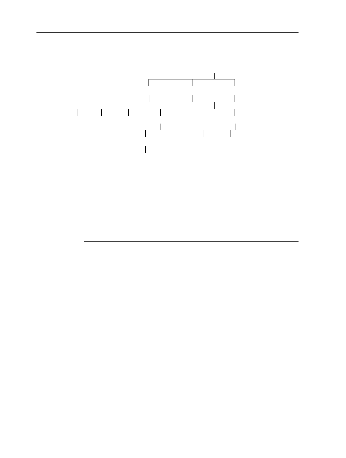
18. NIU TDM configuration options MainStreet Broadband Wireless Technical Practices
Issue 1, April 1999 NNP 95-4882-01-00-A
18-8
DRAFT
To configure the trunk conditioning data and signaling patterns
where
port is 1
channel is an integer from 1 to 24
start is an integer from 1 to 24
end is an integer from 2 to 24, and end must be greater than start
group is an integer from 1 to 24
value is a hexadecimal number from 0 to F
data is a hexadecimal number from 00 to FF
CONFIG — PORT— <port> ↵ — TRUNK_COND
SK002305
<CGgroup> ↵
DATASIGNALING
<channel> ↵<start-end> ↵
CODE_2CODE_1
<value> ↵<data> ↵<value> ↵
CUSTOMIDLEMUX_OOS
DISABLESEIZEDIDLE

MainStreet Broadband Wireless Technical Practices 19. ATM configuration options
NNP 95-4882-01-00-A Issue 1, April 1999
19-1
DRAFT
19. ATM configuration options
This chapter describes how to configure the ATM options for the MainStreet
Broadband Wireless system.
The NIU ATM configuration options are:
•AAL service type
•padding octet value
•playout buffer
•user data octets per cell
The only T-ARIC card ATM configuration option is NIU user data VPI.
19.1 NIU ATM configuration options
AAL service type
Each port is configured to provide either structured or unstructured data transfer.
When a structured data mode is selected (SDT_BASIC and SDT_CAS), framing is
passed or inserted. SDT_CAS mode passes signaling bits on each of the contained
channel groups, while SDT_BASIC removes signaling bits.
When an unstructured data mode is selected (UDT and UDT_PERFMON), framing
is not passed or inserted. UDT_PERFMON allows performance monitoring statistics
to be collected from the port. UDT mode blocks the collection of performance
monitoring statistics.
Caution
Selection of any of the UDT or SDT keys removes all configured channel groups and
connections on the port.
Note 1
CAS cannot be selected on E1 ports that are configured for 31-channel framing.
Note 2
RBS and zero suppression options are available only for SDT_BASIC, SDT_CAS and
UDT_PERFMON mode.

19. ATM configuration options MainStreet Broadband Wireless Technical Practices
Issue 1, April 1999 NNP 95-4882-01-00-A
19-2
DRAFT
To configure the AAL service type
From the NIU NMTI, enter:
where port is 1
Padding octet value
When valid user data does not occupy all the available octets in an ATM cell, pad
characters are inserted into empty octets by the NIU to maintain a fixed cell size.
The specified pad character is inserted in each unused octet on every connected
channel group.
To configure the padding octet value
From the NIU NMTI, enter:
CONFIG — SYSTEM — PAD_OCTET_VAL — <octet_value> ↵
where octet_value is from 00 to FF
Playout buffer
The playout buffer for each VC has a configurable fill level threshold that provides
buffer underrun protection. Adjust the playout buffer fill level threshold to balance
larger playout buffer delay requirements against greater underrun protection, to suit
the particular network conditions or application. The default fill level provides 3 ms
of underrun protection.
CONFIG — PORT — <port> ↵ — OPTIONS — AAL_SERVICE
SK002301
UDT_PERFMONSDT_BASIC UDTSDT_CAS

MainStreet Broadband Wireless Technical Practices 19. ATM configuration options
NNP 95-4882-01-00-A Issue 1, April 1999
19-3
DRAFT
To configure the playout buffer threshold
From the NIU NMTI, enter:
CONFIG — PORT — <port> ↵ — OPTIONS — AAL_SERVICE — OPTIONS —
PLAYOUT_BUFF — <threshold> ↵
where
port is 1
threshold is from 0 to 6 s in increments of 0.5 s
User data octets per cell
For each channel group, the number of octets per cell that are reserved for user data
can be configured as a number from 1 to 46.
To configure the maximum value of 46, select ALL.
To configure the user data octets per cell
From the NIU NMTI, enter:
where
group is an integer from 1 to 24 for T1 NIUs, or 1 to 31 for E1 NIUs
octet_count is an integer from 1 to 46
CONFIG — CHANNELGROUP— <CGgroup> ↵ — OPTIONS — NUM_DATA_OCT
SK002303
<octet-count> ↵
ALL

19. ATM configuration options MainStreet Broadband Wireless Technical Practices
Issue 1, April 1999 NNP 95-4882-01-00-A
19-4
DRAFT
19.2 T-ARIC card ATM configuration options
NIU user data VPI
User data connections to a specific NIU are made through a VPI that is unique to that
NIU. Each NIU must be configured for a unique VPI before the NIU can
communicate with the BTS.
To configure the NIU user data VPI
From the MainStreetXpress 36170 NMTI, enter:
CONFIG — MORE — BTS — NIU — <NIU_id> ↵ — DATA_VPI — <vpi_number> ↵
where
NIU_id is an integer from 100 to 3299
vpi_number is an integer from 0 to 249

MainStreet Broadband Wireless Technical Practices 20. SNMP configuration options
NNP 95-4882-01-00-A Issue 1, April 1999
20-1
DRAFT
20. SNMP configuration options
This chapter describes how to configure the SNMP options supported by the NIUs.
20.1 SNMP access communities
This section describes how to:
•configure access community privileges
•configure a community name
•configure an element manager IP address
•delete access communities
To configure access privileges, name and IP address
where
community_id is an integer from 1 to 10
community_name is a string of up to 16 characters excluding spaces, tabs, question marks and percent signs
ip_address is in the decimal format #.#.#.#, where # is an integer from 0 to 255
CONFIG — SYSTEM — SNMP — ACCESS — EDIT — <community_id> ↵
SK002299
IP_ADDRESSNAME PRIVILEGE
READ_WRITENONE UNASSIGNEDREAD
<community_name> ↵<ip_address> ↵

20. SNMP configuration options MainStreet Broadband Wireless Technical Practices
Issue 1, April 1999 NNP 95-4882-01-00-A
20-2
DRAFT
To delete access communities
where community_id is an integer from 1 to 10
20.2 SNMP trap communities
This section describes how to:
•enable or disable a trap community
•configure a trap community name
•configure an element manager IP address
•delete a trap community
To enable or disable a trap community
CONFIG — SYSTEM — SNMP — TRAPS — EDIT — <community_id> ↵ —
ENABLE/DISABLE*
where community_id is an integer from 1 to 10
To configure a trap community name
CONFIG — SYSTEM — SNMP — TRAPS — EDIT — <community_id> ↵ — NAME —
<community_name> ↵
where
community_id is an integer from 1 to 10
community_name is a string of up to 16 characters excluding spaces, tabs, question marks and percent signs
To configure an element manager IP address
CONFIG — SYSTEM — SNMP — TRAPS — EDIT — <community_id> ↵ — IP_ADDRESS —
<ip_address> ↵
where
community_id is an integer from 1 to 10
ip_address is in the decimal format #.#.#.#, where # is an integer from 0 to 255
CONFIG — SYSTEM — SNMP — ACCESS
SK002300
DELETE_ALLDELETE
<community_id> ↵

MainStreet Broadband Wireless Technical Practices 20. SNMP configuration options
NNP 95-4882-01-00-A Issue 1, April 1999
20-3
DRAFT
To delete trap communities
where community_id is an integer from 1 to 10
CONFIG — SYSTEM — SNMP — TRAPS
SK002297
DELETE_ALLDELETE
<community_id> ↵


MainStreet Broadband Wireless Technical Practices 21. Air interface configuration
NNP 95-4882-01-00-A Issue 1, April 1999
21-1
DRAFT
21. Air interface configuration
This chapter describes the functionality and configuration of the T-ARIC card and
NIU air interface parameters.
21.1 Air interface-related parameters
Table 21-1 and 21-2 lists the air interface parameters and provides references to
explanations of the functionality and configuration.
Table 21-1: T-ARIC card air interface parameters
Parameter Functionality
description Configuration procedure
Add NIU 21.5 21.13
Card type 21.8 21.16
Contention timeslots 21.9 21.13
Demodulator 21.9 21.13
Downstream channel frequency 21.3 21.12
Downstream channel width 21.3 21.12
Downstream IF start 21.3 21.11
Group number 21.4 21.11
NIU ID 21.5 21.14
Guard timeslots – see Timeslots reserved
for guard timeslots 21.9 21.13
NIU serial number 21.5 21.14
NIU type 21.5 21.14
Polling timeslots – see Timeslots reserved
for polling slots 21.9 21.13
Port name 21.15 21.15
Reference point 3.7.7 21.15
Reserved timeslots – see Timeslots
reserved for DBA NIU connections 21.9 21.13
Rx control 21.7 21.11
Rx LO offset 21.2 21.11
Rx RF upstream frequency end 21.3 21.11
Rx RF upstream frequency start 21.3 21.11
Slot name 21.8 21.16
Timeslots reserved for guard slots 21.9 21.13

21. Air interface configuration MainStreet Broadband Wireless Technical Practices
Issue 1, April 1999 NNP 95-4882-01-00-A
21-2
DRAFT
Table 21-2: NIU air interface parameters
Timeslots reserved for NIU contention (for
E1 and T1 NIUs) 21.9 21.13
Timeslots reserved for polling slots 21.9 21.13
Timeslots reserved for DBA NIU
connections 21.9 21.13
Tx control 21.7 21.11
Tx default power level 21.6 21.12
Tx power level 21.6 21.12
Tx power level status 21.6 21.12
Tx RF downstream frequency end 21.3 21.11
Tx RF downstream frequency start 21.3 21.11
Upstream channel frequency 21.3 21.13
Upstream IF start 21.3 21.11
Upstream IF frequency offset 21.3 21.11
Parameter Functionality
description Configuration procedure
Add frequency 21.3 21.10
Channel bandwidth, frequency and
number of channels 21.3 21.10
Downstream frequency offset 21.2 21.10
Power level (maximum) after network
entry 21.6 21.10
Power level (maximum) before network
entry 21.6 21.10
Power level (minimum) after network entry 21.6 21.10
Power level (minimum) before network
entry 21.6 21.10
Tx LO offset 21.2 21.10
Rx LO offset 21.2 21.10
RF band start frequency 21.2 21.10
RF band end frequency 21.2 21.10
IF band start frequency 21.2 21.10
Parameter Functionality
description Configuration procedure

MainStreet Broadband Wireless Technical Practices 21. Air interface configuration
NNP 95-4882-01-00-A Issue 1, April 1999
21-3
DRAFT
21.2 Frequency offsets
This section describes the functions of:
•downstream frequency offset for the NIUs
•Rx LO offset for the T-ARIC card
Downstream frequency offset
There is a fixed RF range for which the transceiver radio can receive signals over the
air. Likewise, there is a fixed IF range for which the transceiver radio can transmit to
the NIU modem. Radios that are supplied by different manufacturers do not
necessarily support the same IF range, even though the radios support the same RF
range.
The downstream frequency offset provides a method of compensating for
differences between the modem and transceiver IF spectrums. The value configured
as the downstream frequency offset is the difference between the modem IF range
and the transceiver IF range.
For Release 1.1, keep the downstream frequency offset at the default value (0).
Rx LO offset
There is a fixed RF range for which the BTS Rx radio can receive signals over the air.
Likewise, there is a fixed IF range for which the BTS OTU can transmit to the T-ARIC
modem. Ideally, the IF spectrum should be the same for the OTU, ORU and modem.
The Rx LO offset compensates for differences between the modem and the Rx radio
IF spectrums. The value configured as the Rx LO offset is the difference between the
modem IF range and the ORU IF range.
For Release 1.1, keep the Rx LO offset at the default value (150).

21. Air interface configuration MainStreet Broadband Wireless Technical Practices
Issue 1, April 1999 NNP 95-4882-01-00-A
21-4
DRAFT
21.3 Frequency utilization
This section describes:
•add frequency
•channel bandwidth
•channel frequency
•number of channels
•downstream channel frequency and bandwidth
•downstream IF start frequency
•Rx RF upstream frequency start and end
•Tx RF downstream frequency start and end
•upstream channel frequency
•upstream IF start frequency
Figure 21-1 shows two T-ARIC cards and two NIUs. The T-ARIC cards and NIUs are
part of the same sector. Other T-ARIC cards and NIUs in the sector are not shown.
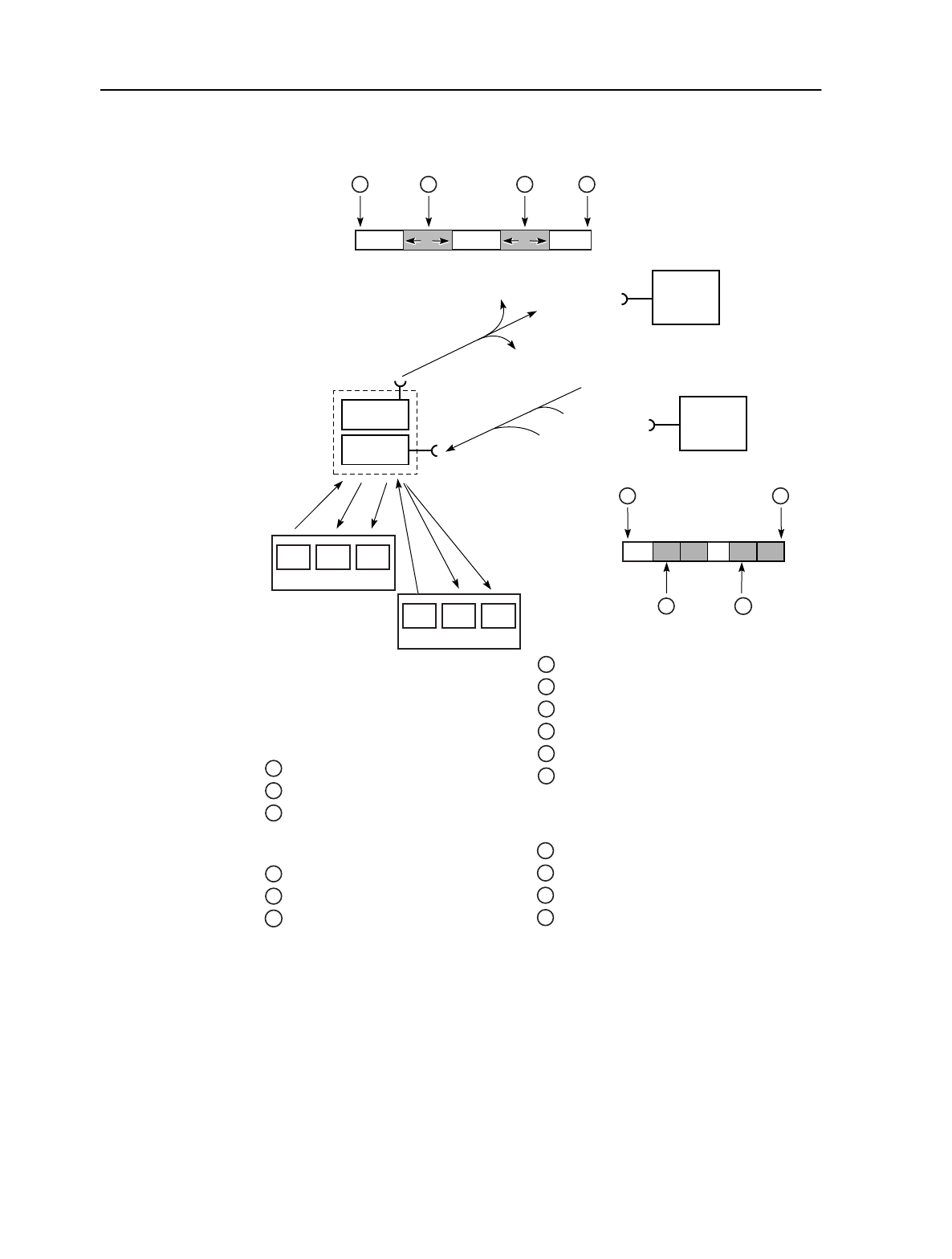
MainStreet Broadband Wireless Technical Practices 21. Air interface configuration
NNP 95-4882-01-00-A Issue 1, April 1999
21-5
DRAFT
Figure 21-1: RF frequency utilization
CTL 2 4 (a)CTL 2 4 (a)
Downstream
RF
1 3 5 2
CTL 23 4 (a)1CTL 23 4 (a)1
Upstream
RF
7
910
8
11444
NIU 1NIU 1NIU 1
Tx
Rx
11444
NIU 1NIU 1NIU 2
Tx
Rx
To NIU 2
From NIU 2
From NIU 1
To NIU 1
To other NIUs
in the sector
From other NIUs
in the sector
46
D1 Up1 Up2
T-ARIC #1 Port 1
D1 Up1 Up2
T-ARIC #2 Port 1 NIU #1 configuration
1
2
7
8
3
4
Tx downstream RF start
Tx downstream RF end
Rx upstream RF start
Rx upstream RF end
1
2
7
8
Tx downstream RF start
Tx downstream RF end
Rx upstream RF start
Rx upstream RF end
Downstream channel centre frequency
Downstream channel width
T-ARIC configuration
group level
3
4
9
Downstream channel centre frequency
Downstream channel width
Upstream 1 channel centre frequency
Port level (T-ARIC #1)
5
6
10
Downstream channel centre frequency
Downstream channel width
Upstream 1 channel centre frequency
Port level (T-ARIC #2)
11444
OTU
ORU
Tx
Rx

21. Air interface configuration MainStreet Broadband Wireless Technical Practices
Issue 1, April 1999 NNP 95-4882-01-00-A
21-6
DRAFT
Channel bandwidth, frequency and number of channels
Each T-ARIC card in the T-ARIC group transmits downstream on a different
frequency range, called the downstream RF channel (see 3 and 4 in Figure 21-1). An
RF channel is defined by the channel frequency and the channel bandwidth. You
must configure each NIU to receive in the appropriate RF channel. The add
frequency feature allows you to create a list of channels; the NIU attempts to connect
to each channel in turn until a connection is established.
When you add a channel to a list of channels, specify the channel frequency and the
channel bandwidth. The channel frequency, or the center of the RF channel, is fixed
at 18 MHz.
You can create multiple RF channels simultaneously by specifying the lowest center
RF, the channel bandwidth and the number of channels you want to create. The
channels run consecutively.
The system assigns a unique channel identifier in the range 1 to 30 for each channel.
Downstream channel frequency and bandwidth
Each T-ARIC card in a T-ARIC group transmits downstream on a different
frequency range, called the downstream RF channel. An RF channel is defined by the
channel frequency and the channel bandwidth. You must specify a channel
bandwidth and a channel frequency for each T-ARIC card in a T-ARIC group (see 3
and 4 in Figure 21-1). The channels cannot overlap.
The channel frequency, or the center of the RF channel, is fixed at 18 MHz.
Although it is not strictly necessary, it is good practice to configure all RF channels
to use contiguous bandwidth.
Downstream IF start frequency
Communication between a Modem module located on a T-ARIC card and an ORU
or OTU are in the IF spectrum. Each T-ARIC card in a T-ARIC group uses a different
downstream IF frequency range. You must specify the start (that is, the lowest)
downstream IF frequency. The other IF ranges are determined by the T-ARIC card
and are not user-configurable.
Rx upstream frequency start and end
Each T-ARIC card in the T-ARIC group receives upstream on a different frequency
range, called the upstream RF channel. An RF channel is defined by the channel
frequency and the channel bandwidth. At the T-ARIC group level, you must
configure the upstream RF start and end frequency (see 7 and 8 in Figure 21-1).
The upstream RF frequency start is the lower limit of the lowest upstream RF
channel. The upstream RF frequency end is the higher limit of the highest RF
upstream channel.

MainStreet Broadband Wireless Technical Practices 21. Air interface configuration
NNP 95-4882-01-00-A Issue 1, April 1999
21-7
DRAFT
Tx downstream frequency start and end
Each T-ARIC card in a T-ARIC group transmits downstream on a different
frequency range, called the downstream RF channel. An RF channel is defined by the
channel frequency and the channel bandwidth. At a T-ARIC group level, you must
configure the downstream RF start frequency and end frequency (see 1 and 2 in
Figure 21-1).
The downstream RF frequency start is the lower limit of the lowest downstream RF
channel. The downstream RF frequency end is the higher limit of the highest RF
downstream channel.
Upstream channel frequency
Each T-ARIC card in a T-ARIC group receives upstream on a different frequency
range, called the upstream RF channel. An RF channel is defined by the channel
frequency and the channel bandwidth. The upstream channel width is fixed at
9 MHz. You must specify a channel frequency for each T-ARIC card in a T-ARIC
group (see 9 and 10 in Figure 21-1). The channels cannot overlap.
The channel frequency is the center of the RF channel; the channel width is 9 MHz.
For example, if you specify a channel frequency of 27 355 MHz, the channel itself
begins at 27 350.5 MHz and ends at 27 359.5 MHz.
Although a T-ARIC card receives on two separate RF channels, specify the channel
frequency for one channel only. If you configure the upstream channel frequency for
upstream 1, then the channel frequency for upstream 2 is automatically set to the
channel frequency for upstream 1 plus 9 MHz. If you configure the upstream
channel frequency for upstream 2, then the channel frequency for upstream 1 is
automatically set to the channel frequency for upstream 2 minus 9 MHz.
Although it is not strictly necessary, it is good practice to configure all RF channels
to use contiguous bandwidth.
Upstream IF start frequency
Communications between a Modem module located on a T-ARIC card and an
OTU/ORU are in the IF spectrum. Each T-ARIC card in a T-ARIC group uses a
different upstream IF frequency range. You must configure the start (that is, the
lowest) upstream IF frequency. The other IF ranges are determined by a T-ARIC card
and are not user-configurable.
Upstream frequency offset
The T-ARIC card must know the beginning of the NIU Tx IF band in order to
communicate with the NIU. The upstream frequency offset is used by the BTS to
calculate the NIU Tx IF band. The frequency offset is defined as the CPE IF start
frequency minus the BTS IF start frequency. Therefore, if the BTS IF start frequency
is 400 MHz, and the CPE IF start frequency is 550 MHz, configure the upstream
frequency offset as -150 MHz. This will allow the BTS to communicate with the NIU
on the appropriate IF frequency.

21. Air interface configuration MainStreet Broadband Wireless Technical Practices
Issue 1, April 1999 NNP 95-4882-01-00-A
21-8
DRAFT
21.4 Groups
You can connect up to 12 T-ARIC cards and configure them to use the same
OTU/ORU. Some configurable parameters can be common to each of the T-ARIC
cards in the group.
Note that even single T-ARIC cards must belong to a group; in this case, the group
has only one T-ARIC card.
21.5 NIU
The following parameters are configurable on a T-ARIC card:
•add NIU
•NIU ID
•NIU serial number
•NIU type
Add NIU
Before the system can establish any communication over the air interface, you must
configure each T-ARIC card with the NIU ID of each NIU that a T-ARIC card is to
communicate with. This procedure consists of adding each NIU to one of the two
demodulators on a T-ARIC card.
NIU ID and NIU serial number
Each NIU is physically configured at the time of manufacture with a unique NIU
serial number of up to 19 characters.
You must configure the NIU with an NIU ID in the range 100 to 3299. The NIU ID
must be unique within a BTS, but the same NIU ID can be used in more than one
BTS.
During configuration of the T-ARIC card, you must associate each NIU with one of
the two T-ARIC card upstreams, by programming the T-ARIC card upstream with
the NIU ID.
NIU type
The MainStreet Broadband Wireless system supports only CE NIUs.

MainStreet Broadband Wireless Technical Practices 21. Air interface configuration
NNP 95-4882-01-00-A Issue 1, April 1999
21-9
DRAFT
21.6 Power level
This section describes the functions of:
•maximum power level after network entry
•maximum power level before network entry
•minimum power level after network entry
•power level before network entry
•Tx power level
•Tx power level status
NIU power level functions
For each NIU, configure the maximum and minimum power levels that the NIU will
operate at, both before and after the NIU enters the network. The process of entering
the network is called network registration.
Figure 21-2 shows relative values for the minimum and maximum NIU transmit
values before and after network entry.
Figure 21-2: NIU power levels before and after network entry
The minimum and maximum transmit power levels used before network entry are
a subset of the transmit values that are used after network entry. The BTS is able to
receive from the NIU at the minimum transmit power level in normal operating
conditions. If the BTS does not respond, the NIU increases the transmit power until
the maximum transmit power level is reached.
The purpose of configuring a maximum power level before network entry is to
prevent the NIU from interfering with other equipment. If an NIU transceiver is not
aligned with a BTS, and if there were no maximum transmit limit, the NIU would
continue to increase the transmit power and ultimately cause interference with other
network equipment.
After the NIU has registered with the network, the NIU adjusts the transmit power
level in response to the power level received from the BTS. If the receive power level
increases, the NIU lowers the transmit power level; if the receive power level
decreases, the NIU increases the transmit power level.
Transmit power level
0
Before network
entry After network
entry
Maximum
Maximum
Minimum Minimum
11440

21. Air interface configuration MainStreet Broadband Wireless Technical Practices
Issue 1, April 1999 NNP 95-4882-01-00-A
21-10
DRAFT
You should configure the minimum power level used after network entry at a level
that the BTS can always receive.
The minimum power level used after network entry ensures that the NIU cannot
reduce the transmit power level to a level that cannot be received by the BTS. The
maximum power level used after network entry ensures that the NIU does not
increase the transmit power level to a level that interferes with other network
equipment.
The maximum power level used after network entry can be set higher than the
maximum power level used before network entry, because until the NIU has
registered you cannot be certain that the NIU and the BTS are aligned.
The overall intent of providing configurable transmit levels for each NIU is to try to
ensure that the receive power at the BTS is consistent. NIUs that are close to the BTS
have lower transmit power levels than NIUs that are farther away.
21.7 Rx and Tx redundancy
This section describes the functions of:
•Rx control
•Tx control
The MainStreet Broadband wireless system supports redundancy only for the OTUs
and ORUs. Rx and Tx redundancy is supported at the T-ARIC group level; you can
configure each T-ARIC card in the T-ARIC group to control one receiver and/or one
transmitter.
Figure 21-3 shows a T-ARIC group with two T-ARIC cards. T-ARIC 1 is connected
to an OTU and an ORU. T-ARIC 2 is connected to an OTU, but not to an ORU. If the
active transmitter connected to T-ARIC 1 fails, the inactive transmitter connected to
T-ARIC 2 becomes active.
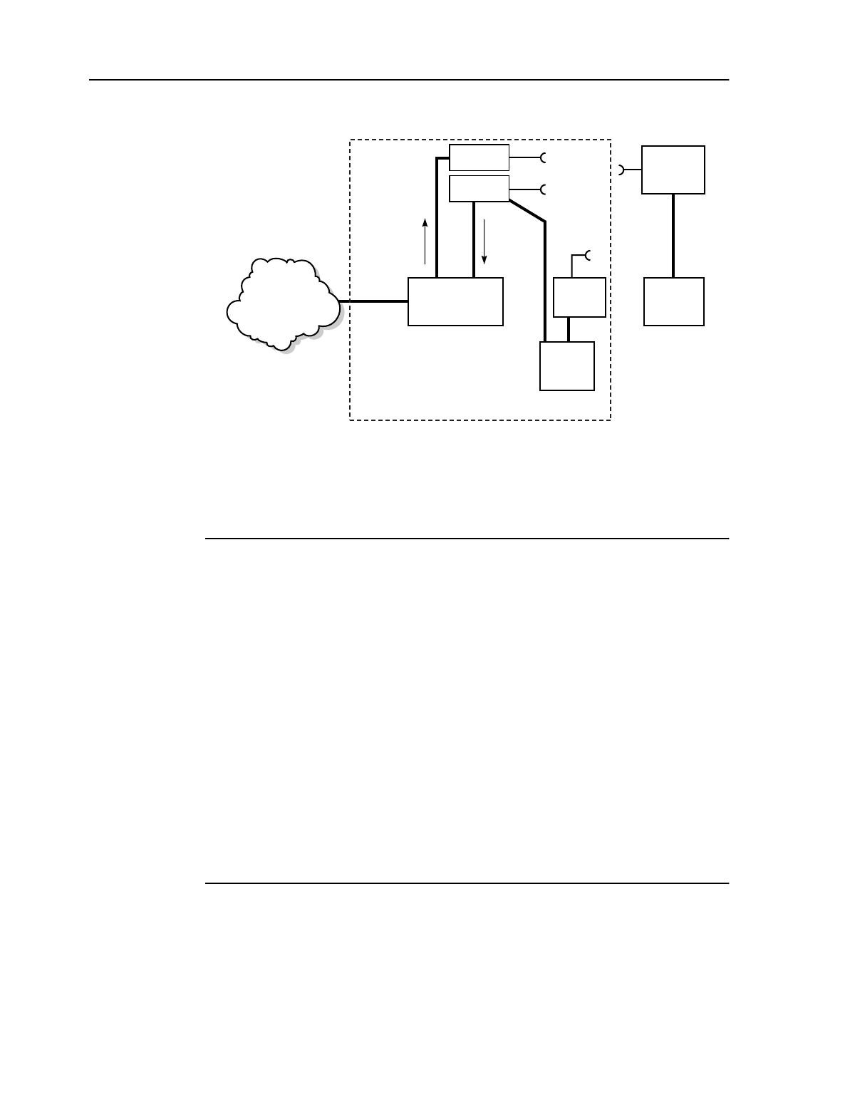
MainStreet Broadband Wireless Technical Practices 21. Air interface configuration
NNP 95-4882-01-00-A Issue 1, April 1999
21-11
DRAFT
Figure 21-3: Tx redundancy
The Rx and Tx control functions provide a method of independently enabling (or
disabling) a receiver and/or a transmitter for each T-ARIC card. A single T-ARIC
card cannot support redundant receivers or transmitters.
21.8 Slot parameters
This section describes the:
•card type
•slot name
Card type
You must configure the T-ARIC slot card type as T-ARIC.
Slot name
You can assign each T-ARIC card slot a name of up to 15 characters.
11438
T-ARIC 2
ATM network
(through
MainStreetXpress
36170)
OTRU
NIU
OTU
Tx
Inactive Tx
Active Tx
Active Rx
T-ARIC group
T-ARIC
Downstream Upstream
OTU
ORU
Tx
Rx

21. Air interface configuration MainStreet Broadband Wireless Technical Practices
Issue 1, April 1999 NNP 95-4882-01-00-A
21-12
DRAFT
21.9 Upstream timeslot utilization
This section describes the parameters:
•contention timeslots
•demodulator status
•guard timeslots
•polling timeslots
•reserved DBA timeslots
You configure these parameters independently for each upstream channel.
Figure 21-4 shows an example of timeslot utilization on an upstream channel.
Figure 21-4: Timeslot utilization on an upstream channel
Contention timeslots
The E1 and T1 NIUs use contention timeslots to communicate with the T-ARIC card.
These timeslots do not carry user data. You configure the number of contention
timeslots independently for each of the two upstream demodulators on the T-ARIC
card.
All NIUs connected to the upstream demodulator share access to the contention
timeslots, but a contention timeslot can only be used by a single NIU at a time. If no
contention timeslots are available and the NIU needs to communicate with the
T-ARIC card, the NIU must make successive attempts until a contention timeslot
becomes available.
At least one timeslot must be reserved for contention. The T-ARIC card determines
the location of the contention timeslots within the upstream channel.
11439
01... ... ... ... ...
15 47 98 102 132
Polling timeslots
Timeslot 0 always
reserved for
polling
Location of
additional polling
slots handled by
T-ARIC
UBR reserved timeslot
location handled
by T-ARIC
Guard timeslots
1 to 3 guard timeslots
immediately follow
timeslot 0
Contention timeslot
location handled by T-ARIC
All non-allocated timeslots
can be used by E1 + T1 NIUS

MainStreet Broadband Wireless Technical Practices 21. Air interface configuration
NNP 95-4882-01-00-A Issue 1, April 1999
21-13
DRAFT
Guard and polling timeslots
During the process of network entry, the NIU attempts to communicate with the
T-ARIC card on an assigned polling slot. Timeslot 0 is called a polling timeslot.
Because the NIUs may not be synchronized with the BTS during the network entry
process, it is possible that the message from the NIU might overflow into the next
timeslot.
Guard slots are timeslots that do not carry user data. Guard slots immediately follow
the polling slot and guarantee that timeslots used for user data are not interfered
with by NIUs attempting to enter the network. At least one timeslot must be
reserved as a guard timeslot, which is why polling timeslots used for network entry
are followed by guard timeslots.
The T-ARIC card continues to poll the NIUs after the NIUs have entered the
network. To prevent congestion on timeslot 0 you can configure additional polling
slots. These polling slots are used only by NIUs that have entered the network, so
guard timeslots are not needed. The T-ARIC card determines the location of any
additional polling timeslots. You only configure the number of polling timeslots.
Reserved DBA timeslots
You configure the number of timeslots that are available for use for
bandwidth-on-demand by NIUs. These timeslots are used for the Ethernet port,
MAC messages and management data.
If no DBA timeslots are reserved, NIU CBR connections might use all available
bandwidth. All NIU connections are CBR.
The T-ARIC card determines the location of the reserved DBA timeslots. You only
configure the number of reserved DBA timeslots.

21. Air interface configuration MainStreet Broadband Wireless Technical Practices
Issue 1, April 1999 NNP 95-4882-01-00-A
21-14
DRAFT
21.10 NIU configuration
This section describes how to configure the following options:
•add frequency
•channel bandwidth
•channel frequency
•number of channels
•delete channel
•maximum power level after network entry
•maximum power level before network entry
•maximum power level after network entry
•maximum power level before network entry
•Tx LO offset
•Rx LO offset
•RF band start frequency
•RF band end frequency
•IF band start frequency
To add frequencies
where
bandwidth is 18 MHz
center_frequency is the center frequency of the downstream channel from 20000 to 40000
roll-off is 0.35
number is an integer from 1 to 30
Note
The NIU verifies that the new parameters do not overlap any existing entries. If the
new parameters do overlap any existing entries, the screen displays an error
message.
CONFIG — SYSTEM — MODEM — MORE — ADD_FREQ
SK002330
<bandwidth, center_frequency, number> ↵
<center_frequency, bandwidth, roll-off, number> ↵

MainStreet Broadband Wireless Technical Practices 21. Air interface configuration
NNP 95-4882-01-00-A Issue 1, April 1999
21-15
DRAFT
To delete channels
Note
The system assigns the channel identifiers that are referred to in this procedure. The
channel identifiers are displayed on the NMTI screen.
where
channel is the channel number to delete
start is the first channel number in the range
end is the last channel number in the range, and end must be greater that start
list is at least two channel numbers separated by a comma
To configure the maximum power level after network entry
CONFIG — SYSTEM — MODEM — MAX_POWER_AFT — <power> ↵
where power is –10 to –60 dB in increments of 40 dB
To configure the maximum power level before network entry
CONFIG — SYSTEM — MODEM — MAX_POWER_BEF — <power> ↵
where power is –10 to –60 dB in increments of 40 dB
To configure the minimum power level before network entry
CONFIG — SYSTEM — MODEM — MIN_POWER_BEF — <power> ↵
where power is –10 to –60 dB in increments of 40 dB
CONFIG — SYSTEM — MODEM — MORE — DEL_FREQ
SK002331
<list> ↵<start-end> ↵<channel> ↵

21. Air interface configuration MainStreet Broadband Wireless Technical Practices
Issue 1, April 1999 NNP 95-4882-01-00-A
21-16
DRAFT
To configure the minimum power level after network entry
CONFIG — SYSTEM — MODEM — MIN_POWER_AFT — <power> ↵
where power is –10 to –60 dB in increments of 40 dB
To configure the Tx LO and Rx LO frequency offsets
CONFIG — SYSTEM — MODEM — LO — <tx_LO, rx_LO> ↵
where
tx_LO is from 17000 to 40000 Mhz
rx_LO is from 17000 to 40000 Mhz
To configure the RF band start and end frequency and IF band start frequency
CONFIG — SYSTEM — MODEM — FREQ — <RF_start, RF_end, IF_start> ↵
where
RF_start is 20000 to 40000 MHz
RF_end is 20000 to 40000 MHz
IF_start is 950 to 2050 MHz
21.11 T-ARIC group configuration
This section describes how to add or remove a T-ARIC card from a group, and how
to configure the following options:
•downstream IF start frequency
•Rx and Tx control
•Rx RF upstream frequency start and end
•Tx RF upstream frequency start and end
•upstream IF start frequency
•upstream frequency offset
For a T-ARIC card to function, it must be configured as part of a T-ARIC group, even
if it is the only card in the group.

MainStreet Broadband Wireless Technical Practices 21. Air interface configuration
NNP 95-4882-01-00-A Issue 1, April 1999
21-17
DRAFT
To add or remove a T-ARIC card to or from a T-ARIC group
where
group_id is an integer from 1 to 64
shelf is P1 to P16
slot is an integer from 1 to 11
.
To configure the downstream IF start frequency
CONFIG — MORE — BTS — ARIC_GROUP — <group_id> ↵ — DOWNSTREAM —
IF_START — <start_if> ↵
where
group_id is an integer from 1 to 64
start_if is an integer from 950 to 2050
To configure Rx and Tx control
where group_id is an integer from 1 to 64
CONFIG — MORE — BTS — ARIC_GROUP — <group_id> ↵
SK002332
RMV_CARDADD_CARD
<shelf-slot-1> ↵
CONFIG — MORE — BTS — ARIC_GROUP — <group_id> ↵
SK002333
RX_CTLTX_CTL
ENABLE/DISABLE

21. Air interface configuration MainStreet Broadband Wireless Technical Practices
Issue 1, April 1999 NNP 95-4882-01-00-A
21-18
DRAFT
To configure the Rx upstream start and end frequency
where
group_id is an integer from 1 to 64
end_RF is an integer from 20000 to 40000
start_RF is an integer from 20000 to 40000
To configure the Tx downstream start and end frequency
where
group_id is an integer from 1 to 64
end_RF is an integer from 20000 to 40000
start_RF is an integer from 20000 to 40000
To configure the upstream IF start frequency
where
group_id is an integer from 1 to 64
start_if is an integer from 400 to 900
CONFIG — MORE — BTS — ARIC_GROUP — <group_id> ↵ — UPSTREAM
SK002334
RF_START
<start_RF> ↵
RF_END
<end_RF> ↵
CONFIG — MORE — BTS — ARIC_GROUP — <group_id> ↵ — DOWNSTREAM
SK002335
RF_START
<start_RF> ↵
RF_END
<end_RF> ↵
CONFIG — MORE — BTS — ARIC_GROUP — <group_id> ↵ — UPSTREAM — IFSTART
SK002336
<start_if> ↵

MainStreet Broadband Wireless Technical Practices 21. Air interface configuration
NNP 95-4882-01-00-A Issue 1, April 1999
21-19
DRAFT
To configure the upstream frequency offset
CONFIG — MORE — BTS — ARIC_GROUP — <group_id> ↵ — UPSTREAM —
FREQ_OFFSET — <offset> ↵
where
group_id is an integer from 1 to 64
offset is an integer from -500 to 0
21.12 Downstream T-ARIC modem configuration
This section describes how to configure:
•downstream channel frequency
•downstream channel bandwidth
•Tx default power level
To configure the downstream channel frequency
CONFIG — OBJECT — PORT — <shelf-slot-1> ↵ — MODEM — DOWNSTREAM —
CHANL_FREQ — <center_frequency> ↵
where
shelf is P1 to P16
slot is an integer from 1 to 11
center_frequency is an integer from 20000 to 40000
To configure the downstream channel width
where
shelf is P1 to P16
slot is an integer from 1 to 11
CONFIG — OBJECT — PORT — <shelf-slot-1> ↵
SK002337
36_MHZ18_MHZ

21. Air interface configuration MainStreet Broadband Wireless Technical Practices
Issue 1, April 1999 NNP 95-4882-01-00-A
21-20
DRAFT
To configure the Tx default power level
where
shelf is P1 to P16
slot is an integer from 1 to 11
power is an integer from –22 to 8 in increments of 2
21.13 Upstream T-ARIC modem configuration
This section describes how to add or remove NIUs, and how to configure:
To add or remove an NIU
where
shelf is P1 to P16
slot is an integer from 1 to 11
niu_id is an integer from 100 to 3299
CONFIG — OBJECT — PORT — <shelf-slot-1> ↵ — MODEM — DOWNSTREAM — IF_POWER — DEF_POWER
SK002341
<power> ↵
•NIU association
•contention timeslots
•demodulator operation
•guard timeslots
•polling timeslots
•reserved NIU DBA timeslots
•upstream channel frequency
CONFIG — OBJECT — PORT — <shelf-slot-1> ↵
SK002343
UPSTREAM_2UPSTREAM_1
REMOVE_NIUADD_NIU
<niu_id> ↵

MainStreet Broadband Wireless Technical Practices 21. Air interface configuration
NNP 95-4882-01-00-A Issue 1, April 1999
21-21
DRAFT
To configure the number of contention timeslots
where
shelf is P1 to P16
slot is an integer from 1 to 11
contention_timeslots is an integer from 2 to (133 minus the number of configured polling slots, minus the
number of configured guard slots)
To configure the demodulator operational status
where
shelf is P1 to P16
slot is an integer from 1 to 11
CONFIG — OBJECT — PORT — <shelf-slot-1> ↵
SK002344
UPSTREAM_2UPSTREAM_1
TS_POOLS
<contention_timeslots> ↵
CONTENTION
CONFIG — OBJECT — PORT — <shelf-slot-1> ↵
SK002345
UPSTREAM_2UPSTREAM_1
ENABLE/
DISABLE

21. Air interface configuration MainStreet Broadband Wireless Technical Practices
Issue 1, April 1999 NNP 95-4882-01-00-A
21-22
DRAFT
To configure the number of guard timeslots
where
shelf is P1 to P16
slot is an integer from 1 to 11
guard_timeslots is an integer from 1 to 3
To configure the number of polling timeslots
where
shelf is P1 to P16
slot is an integer from 1 to 11
poll_timeslots is an integer from 1 to 16
CONFIG — OBJECT — PORT — <shelf-slot-1> ↵
SK002346
UPSTREAM_2UPSTREAM_1
TS_POOLS
<guard_timeslots> ↵
GUARD
CONFIG — OBJECT — PORT — <shelf-slot-1> ↵
SK002347
UPSTREAM_2UPSTREAM_1
TS_POOLS
<poll_timeslots> ↵
POLLING

MainStreet Broadband Wireless Technical Practices 21. Air interface configuration
NNP 95-4882-01-00-A Issue 1, April 1999
21-23
DRAFT
To configure the number of reserved DBA timeslots
where
shelf is P1 to P16
slot is an integer from 1 to 11
UBR_timeslots is an integer from 0 to (133, minus the number of configured polling slots, minus the
number of configured guard slots)
CONFIG — OBJECT — PORT — <shelf-slot-1> ↵
SK002348
UPSTREAM_2UPSTREAM_1
TS_POOLS
<UBR_timeslots> ↵
UBR

21. Air interface configuration MainStreet Broadband Wireless Technical Practices
Issue 1, April 1999 NNP 95-4882-01-00-A
21-24
DRAFT
To configure the upstream channel frequency
Note
Although the T-ARIC card receives on two separate RF channels, you specify the
channel frequency for one of the two channels, but not for both. If you configure the
upstream channel frequency for upstream 1, then the channel frequency for
upstream 2 is automatically set to the channel frequency for upstream 1 plus 9 MHz.
If you configure the upstream channel frequency for upstream 2, then the channel
frequency for upstream 1 is automatically set to the channel frequency for
upstream 2 minus 9 MHz.
where
shelf is P1 to P16
slot is an integer from 1 to 11
center_frequency is the center frequency of the upstream channel from 20000 to 40000
21.14 T-ARIC card NIU configuration
This section describes:
•NIU serial number
•NIU type
To configure the NIU serial number
CONFIG — MORE — BTS — NIU — <niu_id> ↵ — SERIAL_NUM — <serial_number> ↵
where
niu_id is an integer from 100 to 3299
serial_number is up to 19 characters
CONFIG — OBJECT — PORT — <shelf-slot-1> ↵
SK002349
UPSTREAM_2UPSTREAM_1
CHAN_FREQ
<center_frequency> ↵

MainStreet Broadband Wireless Technical Practices 21. Air interface configuration
NNP 95-4882-01-00-A Issue 1, April 1999
21-25
DRAFT
To configure the NIU type
CONFIG — MORE — BTS — NIU — <niu_id> ↵ — CE
where niu_id is an integer from 100 to 3299
21.15 T-ARIC card port configuration
This section describes how to configure the T_ARIC port name.
To configure the T-ARIC card port name
CONFIG — OBJECT — PORT — <shelf-slot-1> ↵ — NAME — <port_name> ↵
where
shelf is P1 to P16
slot is an integer from 1 to 11
port_name is up to 20 characters
21.16 T-ARIC card slot configuration
This section describes how to configure:
•card type
•slot name
To configure the T-ARIC card type
CONFIG — OBJECT — PORT — <shelf-slot-1> ↵ — TYPE — CELL_RELAY — WIRELESS —
ARIC_T
where shelf is P1 to P16
slot is an integer from 1 to 11

21. Air interface configuration MainStreet Broadband Wireless Technical Practices
Issue 1, April 1999 NNP 95-4882-01-00-A
21-26
DRAFT
To configure the T-ARIC card slot name
CONFIG — OBJECT — PORT — <shelf-slot-1> ↵ — NAME — <slot_name> ↵
where
shelf is P1 to P16
slot is an integer from 1 to 11
slot_name is up to 20 characters

MainStreet Broadband Wireless Technical Practices 22. Status information
NNP 95-4882-01-00-A Issue 1, April 1999
22-1
DRAFT
22. Status information
This chapter describes status information that can be viewed on NIUs and T-ARIC
cards.
22.1 Status information
Table 22-1 describes the individual status fields. The fields shown are status fields
only; these fields do not show information about any of the configured parameters.
Table 22-1: Status information
Field Status
E1 port AIS
LOF
LOS
Ok
RAI
NIU network
connectivity Hunting
Modem not configured
Network entered
NIU modem OK
Fault
NIU modem
housekeeper link OK
Link down
NIU status Active (the NIU has been configured, has been associated
with a T-ARIC card port, and has entered the network)
Config (the NIU has been configured, but has not been
associated with a T-ARIC card port)
Pooled (the NIU has been configured and has been
associated with a T-ARIC card port, but has not completed
network entry)
T1 port AIS
LOF
LOS
Ok
RAI
TS16 AIS
TS16 multiframe
TS16 RAI

22. Status information MainStreet Broadband Wireless Technical Practices
Issue 1, April 1999 NNP 95-4882-01-00-A
22-2
DRAFT
To view NIU T1 or E1 port status
From the NIU NMTI, enter:
CONFIG — PORT — <port> ↵
where port is 1
To view base network, NIU modem and housekeeping link status
From the NIU NMTI, enter:
MAINT— SYSTEM — MODEM
To view NIU status
From the MainStreetXpress 36170 NMTI, enter:
CONFIG — OBJECT — BTS — <niu_id> ↵
where niu_id is an integer from 100 to 3299
To view T-ARIC card port status
From the MainStreetXpress 36170 NMTI, enter:
T-ARIC card port Alarm (at least one alarm is logged against this port)
AllIn (all NIUs associated with this port have completed
network entry)
Idle (there are no NIUs associated with this port)
ModemLinkDown (the communication link with the modem is
down)
NoneIn (none of the NIUs associated with this port have
completed network entry)
SomeIn (at least one, but not all, of the NIUs associated with
this port have completed network entry)
TunerLinkDown (the communication link with the tuner module
is down)
T-ARIC card slot RxDown (the receiver controlled by this T-ARIC card is down)
RxLinkDown (the communication link with the receiver is
down)
TxDown (the transmitter controlled by this T-ARIC card is
down)
TxLinkDown (the communication link with the transmitter is
down)
TxRxDown (the transmitter and receiver devices controlled by
this T-ARIC card are both down)
Field Status

MainStreet Broadband Wireless Technical Practices 22. Status information
NNP 95-4882-01-00-A Issue 1, April 1999
22-3
DRAFT
CONFIG — OBJECT — PORT — <shelf-slot-1> ↵
where
shelf is P1 to P16
slot is an integer from 1 to 11
To view T-ARIC card slot status
From the MainStreetXpress 36170 NMTI, enter:
CONFIG — OBJECT — SLOT — <shelf-slot-1> ↵
where
shelf is P1 to P16
slot is an integer from 1 to 11


MainStreet Broadband Wireless Technical Practices 23. T-ARIC card statistics
NNP 95-4882-01-00-A Issue 1, April 1999
23-1
DRAFT
23. T-ARIC card statistics
This chapter describes the T-ARIC card statistics supported on the MainStreet
Broadband Wireless system.
23.1 Statistics
Table 23-1 describes all supported statistics.
Table 23-1: Description of supported statistics
Statistic Description Endpoint or
port Egress or
ingress
Cells Discarded by UPC
(CLP 0) Displays the number of valid cells that have CLP=0 and which have
been discarded at ingress by the ingress traffic policing
This number includes cells with corrected header errors
Endpoint Ingress
Cells Discarded by UPC
(CLP 0+1) Displays the number of valid cells that have CLP=0 or CLP=1, and
which have been discarded at ingress by the ingress traffic policing
This number includes cells with corrected header errors
Endpoint Ingress
Cells Tagged by UPC Displays the number of valid cells with CLP=0 admitted at ingress
and which had CLP set to 1 by the ingress traffic policing
This number includes cells with corrected header errors
Endpoint Ingress
Cells Transmitted Displays the number of valid cells that have been transmitted at
egress Port Egress
Cells Transmitted
(CLP 0) Displays the number of valid cells that have been transmitted at
egress with CLP=0 Endpoint Egress
Cells Transmitted
(CLP 0+1) Displays the number of valid cells that have been transmitted at
egress with CLP=0 or with CLP=1 Endpoint Egress
Valid Cells Received Displays the number of valid cells admitted at ingress Port Ingress
Valid Cells Received
(CLP 0) Displays the number of valid cells with CLP=0 that have been
admitted at ingress
This number includes cells with corrected header errors
Endpoint Ingress
Valid Cells Received
(CLP 0+1) Displays the number of valid cells with CLP=0 or CLP=1, that have
been admitted at ingress
This number includes cells with corrected header errors
Endpoint Ingress

23. T-ARIC card statistics MainStreet Broadband Wireless Technical Practices
Issue 1, April 1999 NNP 95-4882-01-00-A
23-2
DRAFT
To view ATM endpoint statistics
From the MainStreetXpress 36170 NMTI, enter:
STATS — OBJECT — ENDPOINT — <shelf-slot-1;vpi_id/vci_id> ↵ — ATM
where
shelf is P1 to P16
slot is an integer from 1 to 11
vpi_id is an integer from 0 to 249
vci_id is an integer from 32 to 511
To view T-ARIC card port statistics
From the MainStreetXpress 36170 NMTI, enter:
STATS — OBJECT — PORT — <shelf-slot-1> ↵ — ATM
where
shelf is P1 to P16
slot is an integer from 1 to 11
To refresh statistics
From the MainStreetXpress 36170 NMTI, enter:
<Esc> <R>

MainStreet Broadband Wireless Technical Practices 24. NIU statistics
NNP 95-4882-01-00-A Issue 1, April 1999
24-1
DRAFT
24. NIU statistics
This chapter describes the statistics supported by the NIUs.
24.1 NIU port AAL1 statistics
The NIUs provide performance monitoring statistics for each connection at the AAL
layer as required by the ATM Forum B-ICI specification. All statistics are available
in SDT and UDT modes except for AAL1 pointer parity errors and pointer reframes,
which are available only in SDT mode.
Statistics can be viewed for:
•the current 15-minute interval and the 96 previous 15-minute intervals
•previous 24-hour intervals.
Figure 24-1 shows an NIU port AAL1 statistics NMTI display. Table 24-1 lists the
AAL1 statistics supported on the NIU port. AAL1 statistics are only available in
UDT mode.
Figure 24-1: NIU port AAL1 statistics NMTI display
28110 T1 NIU AA1211-R0-AF NIU7:?:? MAJ:Alrm:1 03-JAN-1999 12:56
AAL1 Statistics Valid :CURRENT Worst Interval
00:12:58 -
Reassembled Cells 1000 -
AAL1 Header Errors 2 -
Lost Cells 5 -
Buffer Overflows 3 -
Buffer Starvation/Under flows 3 -
AAL1 Underflow Seconds 3 -
Valid 15-minute intervals 31 (current day)
STATS PORT 1 AAL1 15_MINUTE
1- 2-PREV_INTVL 3-NEXT_INTVL 4-CURRENT 5-INTERVAL_ID
6-TEMP_CLEAR 7- 8-CANCEL 9-QUIT 0-

24. NIU statistics MainStreet Broadband Wireless Technical Practices
Issue 1, April 1999 NNP 95-4882-01-00-A
24-2
DRAFT
Table 24-1: NIU port AAL1 statistics
To view NIU port AAL1 statistics
where
port_id is 1
interval_id is a number from 1 to 96
Statistic Description
AAL1 Reassembled
Cells The number of cells played out to the DS1/E1 service interface,
excluding cells that were discarded
AAL1 Uncorrectable
Header Errors The number of uncorrectable AAL1 header errors detected
AAL1 Lost cells The approximate number of cells lost due to SN continuity errors
AAL1 Buffer Overflows The number of Rx buffer overflows
This counter cannot increment more than once every 100 ms
AAL1 Buffer
Starvation/Underflow The number of Rx buffer underflows
This counter cannot increment more than once every 100 ms
AAL1 Underflow
Seconds The number of seconds during which there was an Rx buffer
underflow
AAL1 Pointer Parity
Errors The number of SDT pointer parity errors
This counter cannot increment more than once every 100 ms
AAL1 Pointer Reframes The number of times that the AAL1 reassembler found that an SDT
pointer was not where it was expected
A pointer must be re-acquired
STATS — PORT— <port_id> ↵ — PHYSICAL
SK002318
24_HOUR15_MINUTE
INTERVAL_ID
<interval_id> ↵
TEMP_CLEAR PREV_INTVL NEXT_INTVL CURRENT

MainStreet Broadband Wireless Technical Practices 24. NIU statistics
NNP 95-4882-01-00-A Issue 1, April 1999
24-3
DRAFT
To view NIU channel group AAL1 statistics
where
group_id is an integer in the range 1 to 24 for T1 NIUs, or 1 to 31 for E1 NIUs
interval_id is a number from 1 to 96
24.2 T1 and E1 statistics
The NIUs collect T1 and E1 statistics that are available for viewing through NMTI.
The 28110 MainStreet T1 NIU collects T1 statistics. The 28120 MainStreet E1 NIU
collects E1 statistics. Statistics can be viewed for the current 15-minute interval and
the 96 previous 15-minute intervals for the T1 and E1 physical statistics.
Figure 24-2 shows T1 statistics for the 28110 MainStreet T1 NIU port. Table 24-2 lists
the T1 statistics supported on the NIU port.
STATS — CHANNEL_GROUP— <group_id> ↵ — AALI
SK002320
24_HOUR15_MINUTE
INTERVAL_ID
<interval_id> ↵
TEMP_CLEARPREV_INTVL NEXT_INTVL CURRENT
TEMP_CLEARPREV_INTVL CURRENT

Figure 24-2: T1 port statistics NMTI display
Table 24-2: T1 port statistics
Note
1. Parameters are supported for UDT only if is in the monitored mode.
The 28120 MainStreet E1 NIU displays G.821 and line error statistics.
Figure 24-3 shows an example of a port G.821 statistics NMTI display for an 28120
MainStreet E1 NIU. Table 24-3 lists the G.821 statistics supported on the NIU port.
28110 T1 NIU AA1211-R0-AF NIU7:?:? MAJ:Alrm:1 03-JAN-1999 12:56
# Type Status Name
1 T1_CE -
Statistics Valid :CURRENT Worst Interval
00:02:11 (02)
Errored Seconds 65 67
Severely Errored Seconds 10 12
Unavailable Seconds 10 11
Bursty Errored Seconds 65 65
Loss of Frame Counts 2 6
Valid 15-minute Intervals 44
STATS PORT 1 PHYSICAL 15_MINUTE
1- 2-PREV_INTVL 3-NEXT_INTVL 4-CURRENT 5-INTERVAL_ID
6-TEMP_CLEAR 7- 8-CANCEL 9-QUIT 0-
Statistic Description AAL1 mode
supported Framing
mode
supported
Errored Seconds The number of seconds during which the
average BER was greater than 0 but less than
1×10⁻³, and a loss of synchronization was not
detected
UDT/SDT SF(D4) / ESF
Severely Errored
Seconds The number of seconds during which the
average BER was greater than 1×10⁻³ or where
a loss of synchronization was detected
UDT/SDT SF(D4)/ESF
Unavailable
Seconds The number of seconds in the selected interval
where the link was in the unavailable state, not
including the 10 severely errored seconds
preceding the unavailable state
UDT(1)/SDT SF(D4)/ESF
Bursty Errored
Seconds The number of seconds in the selected interval
that contained more than one CRC error (in ESF
framing mode) or more than one LCV error (in
D4 framing mode)
UDT(1)/SDT SF(D4)/ESF
Loss of Frame
Count The number of LOF errors that occurred in the
selected interval UDT(1)/SDT SF(D4)/ESF
Valid 15-minute
Intervals The number of valid 15-minute intervals
recorded UDT/SDT SF(D4)/ESF

MainStreet Broadband Wireless Technical Practices 24. NIU statistics
NNP 95-4882-01-00-A Issue 1, April 1999
24-5
DRAFT
Figure 24-3: E1 port G.821 statistics NMTI display
Table 24-3: E1 port G.821 statistics
Figure 24-4 shows an example of a port line error statistics NMTI display for a 28120
MainStreet E1 NIU. Table 24-4 lists the line error statistics supported on the NIU
port.
28120 E1 NIU AA1211-R0-AF NIU7:?:? MAJ:Alrm:1 03-JAN-1999 12:56
# Type Status Name
1 E1_CE120 -
Statistics Interval:CURRENT Worst Interval
00:02:11 (02)
Errored Seconds 65 87
Severely Errored Seconds 10 12
Unavailable Seconds 10 11
Bursty Errored Seconds 65 65
Loss of Frame Count 65 65
Valid 15-minute Intervals 66
STATS PORT 1 PHYSICAL G_821 15_MINUTE
1- 2-PREV_INTVL 3-NEXT_INTVL 4-CURRENT 5-INTERVAL_ID
6-TEMP_CLEAR 7- 8-CANCEL 9-QUIT 0-
Statistic Description AAL1 mode
supported Framing mode
supported
Errored Seconds The number of seconds during which the
average BER was greater than 0 but less
than 1×10⁻³, and a loss of
synchronization was not detected
UDT/SDT G.704
Severely Errored
Seconds The number of seconds during which the
average BER was greater than 1×10⁻³,
or where a loss of synchronization was
detected
UDT/SDT G.704
Unavailable
Seconds The number of seconds in the selected
interval where the link was in the
unavailable state, not including the 10
severely errored seconds preceding the
unavailable state
UDT/SDT G.704
Bursty Errored
Seconds The number of seconds with more than
one CRC error when CRC is enabled
and more than one LCV error when CRC
is disabled
UDT/SDT G.704
Loss of Frame
Count The number of LOF errors that occurred
in the selected interval UDT/SDT G.704
Valid 15-minute
Intervals The number of valid 15-minute intervals
recorded UDT/SDT G.704

24. NIU statistics MainStreet Broadband Wireless Technical Practices
Issue 1, April 1999 NNP 95-4882-01-00-A
24-6
DRAFT
Figure 24-4: E1 port line error statistics NMTI display
Table 24-4: E1 port line error statistics
28120 E1 NIU AA1211-R0-AF NIU7:?:? MAJ:Alrm:1 03-JAN-1999 12:56
# Type Status Name
1 E1_CE120 -
Statistics Interval:CURRENT Worst Interval
00:02:11 (02)
Line Code Violations 65 87
Far End Block Errors 10 12
Frame Alignment Signal Errs 10 11
CRC4 Errors 65 65
Valid 15-minute Intervals 66
STATS PORT 1 PHYSICAL LINE_ERROR 15_MINUTE
1- 2-PREV_INTVL 3-NEXT_INTVL 4-CURRENT 5-INTERVAL_ID
6-TEMP_CLEAR 7- 8-CANCEL 9-QUIT 0-
Statistic Description AAL1 mode
supported Framing
mode
supported
Line Code
Violations The number of BPV or EXZ error events that
occurred during the selected interval UDT/SDT G.704
Far End Block
Errors The number of ES or SES error events that
occurred at the far end of the path during the
selected interval
UDT/SDT G.704
Frame Alignment
Signal Errors The number of consecutive errored FAS that
occurred during the selected interval UDT/SDT G.704
CRC4 Errors The number of CRC-4 errors that occurred
during the selected interval UDT/SDT G.704

MainStreet Broadband Wireless Technical Practices 24. NIU statistics
NNP 95-4882-01-00-A Issue 1, April 1999
24-7
DRAFT
To view NIU T1 port statistics
where
port_id is 1
interval_id is a number from 1 to 96
To view NIU E1 port G.821 statistics
where
port_id is 1
interval_id is a number from 1 to 96
STATS — PORT— <port_id> ↵ — PHYSICAL
SK002318
24_HOUR15_MINUTE
INTERVAL_ID
<interval_id> ↵
TEMP_CLEAR PREV_INTVL NEXT_INTVL CURRENT
STATS — PORT— <port_id> ↵ — PHYSICAL — G_821
SK002317
24_HOUR15_MINUTE
INTERVAL_ID
<interval_id> ↵
TEMP_CLEAR PREV_INTVL NEXT_INTVL CURRENT

24. NIU statistics MainStreet Broadband Wireless Technical Practices
Issue 1, April 1999 NNP 95-4882-01-00-A
24-8
DRAFT
To view NIU E1 port line error statistics
where
port_id is 1
interval_id is a number from 1 to 96
To refresh statistics
<Esc> <R>
STATS — PORT— <port_id> ↵ — PHYSICAL — LINE_ERROR
SK002316
24_HOUR15_MINUTE
INTERVAL_ID
<interval_id> ↵
TEMP_CLEAR PREV_INTVL NEXT_INTVL CURRENT

MainStreet Broadband Wireless Technical Practices 25. LED activity
NNP 95-4882-01-00-A Issue 1, April 1999
25-1
DRAFT
25. LED activity
This chapter describes T-ARIC card and NIU LED activity.
25.1 LED activity
This section describes the LED activity on both the T-ARIC card and on NIUs.
NIU LED activity
Table 25-1 describes NIU LED activity.
Table 25-1: NIU LED activity
LED Color/activity Description
ATM egress
data Green/flashing Valid user egress data is detected. The LED lights for 20 ms
for each cell that is detected.
ATM ingress
data Green/flashing Valid user ingress data is detected. The LED lights for 20 ms
for each cell that is detected.
Basestation
connectivity Green/continuous The NIU has locked on to the downlink frequency.
Green/flashing The NIU is hunting for the downlink frequency.
Red/continuous No downlink frequencies have been programmed on the NIU.
E1/T1 alarm Off No local or remote alarms are detected on the port.
Red/continuous The port is in a local alarm state. One of the following alarms
has occurred: AIS, LIS, LOF, OOF, TS16 AIS or TS16 LOF.
Yellow/continuous The port is in a remote alarm state. One of the following
alarms has occurred: RDI or TS16 RDI.
E1/T1 signal Green/continuous The port is receiving a signal other than AIS, LIS, or TS16 AIS.
Off The port has not been enabled.
Red/continuous The port is receiving an LIS.
Yellow/continuous The port is receiving AIS or TS16 AIS.
Ethernet Link Green/continuous A connection to other Ethernet equipment is detected.
Ethernet Activity Green/continuous Ethernet frames are being received.
Power Green/continuous +5 V is present.
Status Green/continuous There are no critical or major alarms on the NIU.
Red/continuous There is at least one critical or major alarm on the NIU.

25. LED activity MainStreet Broadband Wireless Technical Practices
Issue 1, April 1999 NNP 95-4882-01-00-A
25-2
DRAFT
T-ARIC card LED activity
Table 25-2 describes the T-ARIC card LED activity.
Table 25-2: T-ARIC card LED activity
LED Color/activity Description
Active Green/continuous The card is functioning.
Green/flashing The card is not using the preferred fabric.
Red/continuous The card is malfunctioning.
Alarm Off Currently, there are no critical or major alarms on the
T-ARIC card.
Red/continuous There is at least one critical or major alarm on the T-ARIC
card.
Link Green/continuous All NIUs associated with this T-ARIC card have completed
network entry.
Green/flashing At least one NIU has completed network entry, and at least
one NIU has not completed network entry.
Off There are no NIUs associated with the T-ARIC card.
Yellow/continuous None of the NIUs associated with this T-ARIC card have
completed network entry.
Status Green/continuous The card is in service.
Green/flashing The card has not been recognized by the Control card.
Green and
red/flashing The card installed in the slot does not match the slot
configuration.
Off The card is not powered up, or the LED has failed.
Red/continuous The card is in a failed state. An alarm is generated to
indicate the nature of the card failure.

MainStreet Broadband Wireless Technical Practices 26. Loopbacks
NNP 95-4882-01-00-A Issue 1, April 1999
26-1
DRAFT
26. Loopbacks
This chapter describes the loopbacks supported by the T-ARIC card and the 28110
and 28120 MainStreet NIUs.
26.1 T-ARIC card loopbacks
The T-ARIC card supports segment and end-to-end OAM loopbacks.
Prior to initiating an OAM loopback:
•each node on the path must be configured with a unique CPSS address
•each port on the path must be configured with an appropriate port reference
point type
•each endpoint on the path must be configured with an appropriate OAM
segment type
To configure the T-ARIC card port reference point
where
shelf is P1 to P16
slot is an integer from 1 to 11
CONFIG — OBJECT — PORT — <shelf-slot-1> ↵ — OPTIONS
SK002351
UNI
REFERENCE_PT
B-ISSIB-ICI

26. Loopbacks MainStreet Broadband Wireless Technical Practices
Issue 1, April 1999 NNP 95-4882-01-00-A
26-2
DRAFT
To configure the OAM segment type
where
shelf is P1 to P16
slot is an integer from 1 to 11
vpi_id is an integer from 0 to 249
vci_id is an integer from 32 to 511
To initiate an OAM loopback
where
shelf is P1 to P16
slot is an integer from 1 to 11
vpi_id is an integer from 0 to 249
vci_id is an integer from 32 to 511
CONFIG — OBJECT — PORT — <shelf-slot-1/vpi_id;vci_id> ↵ — OPTIONS
SK002352
TERMINATION
OAM_SEGMENT
INTERMEDIATE
MAINT — OBJECT — ENDPOINT — <shelf-slot-1/vpi_id;vci_id> ↵ — LPB — CELL — TEST
SK002353
END-TO-ENDINTERMEDIATE

MainStreet Broadband Wireless Technical Practices 26. Loopbacks
NNP 95-4882-01-00-A Issue 1, April 1999
26-3
DRAFT
26.2 28110 and 28120 MainStreet NIU loopbacks
The NIUs support line and equipment loopbacks.
To initiate, clear or reset an NIU loopback
where port is 1
MAINT — PORT — <port> ↵ — LOOPBACK
SK002354
LINEEQUIPMENT
CLEARTIMEDLATCHED


MainStreet Broadband Wireless Technical Practices 27. Alarms
NNP 95-4882-01-00-A Issue 1, April 1999
27-1
DRAFT
27. Alarms
This chapter describes all alarms supported by the T-ARIC card and the NIUs, and
describes how to:
•acknowledge alarms
•clear alarms
•configure remote alarm logging over CPSS (available only for the T-ARIC card)
•configure remote alarm logging over SNMP
•configure the alarm queue overflow method
•configure the remote alarm queue overflow method
•delete alarms
•filter the alarm display
•view alarms in a specific queue
•view an alarm summary
Note
Uncleared diagnostic alarms are never counted in any of the outstanding alarms
fields.
27.1 Alarm descriptions
Table 27-1 summarizes NIU alarms. Table 27-2 summarizes T-ARIC card alarms.
Table 27-1: NIU alarm descriptions
Alarm Raised by Queue Description
AIS 28110 and 28120
MainStreet NIUs Minor The monitored port is receiving an AIS indication.
Buffer Overrun 28110 and 28120
MainStreet NIUs Major The egress AAL-1 buffer has overflowed.
alarm clear time: 12.5 s
alarm declare time: 0 s
Buffer Starvation 28110 and 28120
MainStreet NIUs Major The egress AAL-1 buffer has entered the starvation state.
alarm clear time: 12.5 s
alarm declare time: 2.5 s
Line Loopback
Activated 28110 MainStreet
NIU Major A loopback has been raised as a result of in-band signaling
that has been received from the far end.
LOF 28110 and 28120
MainStreet NIUs Major The monitored port has either lost framing, or framing
cannot be detected.
LOS 28110 and 28120
MainStreet NIUs Major The received signal does not contain sufficient ones
density.

27. Alarms MainStreet Broadband Wireless Technical Practices
Issue 1, April 1999 NNP 95-4882-01-00-A
27-2
DRAFT
Table 27-2: T-ARIC card alarm descriptions
Modem Configuration
Fault 28110 and 28120
MainStreet NIUs Major The modem is incorrectly configured.
Modem Device Alarm 28110 and 28120
MainStreet NIUs Critical There is a problem with the modem physical layer, or the
modem has lost communication with the basestation.
Over Temperature
Alarm 28110 and 28120
MainStreet NIUs Major The temperature of the NIU has exceeded 50°C (122°F).
RAI 28110 and 28120
MainStreet NIUs Minor The monitored port is receiving an RAI notification.
System Restart 28110 and 28120
MainStreet NIUs Major The housekeeper processor has restarted. There is no
associated clearing alarm.
TS16 AIS 28120 MainStreet
NIU Major The monitored port is receiving an AIS indication in timeslot
16.
TS16 Multiframe 28120 MainStreet
NIU Major The monitored port is detecting a loss of multiframe in
timeslot 16.
TS16 RAI 28120 MainStreet
NIU Major The monitored port is receiving an RAI indication in timeslot
16.
Alarm Queue Description
Downconverter LO Not
Locked Major The specified downconverter is not locked to the programmed operating
frequency.
NIU Entered Network Diagnostic An NIU (identified by the NIU ID) has established communications with the
T-ARIC.
NIU Left Network Diagnostic An NIU (identified by the NIU ID) has lost communications with the T-ARIC.
Rx LO Not Locked Major The T-ARIC Rx LO is not locked to the programmed operating frequency.
Tx LO Not Locked Major The T-ARIC Tx LO is not locked to the programmed operating frequency.
Upconverter LO Not
Locked Major The T-ARIC is not locked to the programmed operating frequency.
Alarm Raised by Queue Description
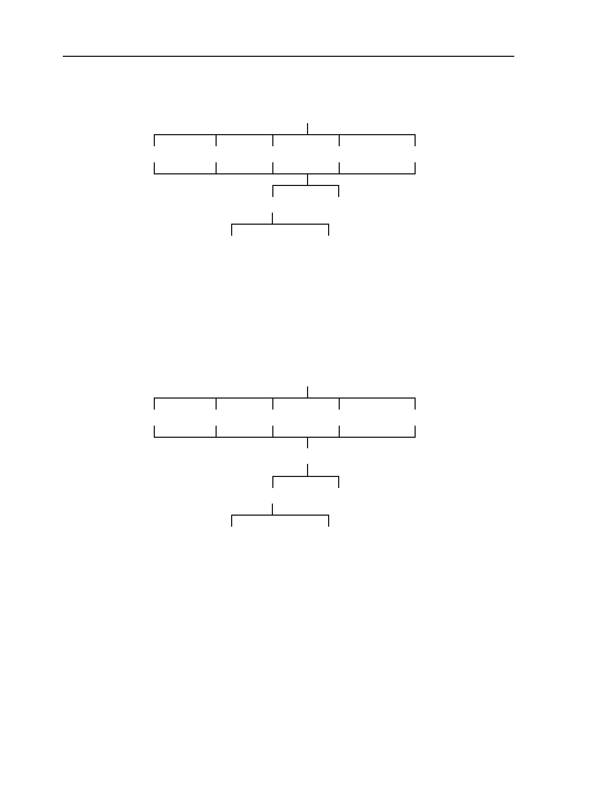
MainStreet Broadband Wireless Technical Practices 27. Alarms
NNP 95-4882-01-00-A Issue 1, April 1999
27-3
DRAFT
To acknowledge alarms
where
alarm_id is the alarm number listed under the #### column on the screen
alarm1_id is the alarm number (under the #### column) of the first alarm in the range
alarm2_id is the alarm number (under the #### column) of the last alarm in the range
To clear alarms
where
alarm_id is the alarm number listed under the #### column on the screen
alarm1_id is the alarm number (under the #### column) of the first alarm in the range
alarm2_id is the alarm number (under the #### column) of the last alarm in the range
ALARMS — OUTSTANDING
SK002355
ALL_ALARMSCRITICAL MINORMAJOR DIAGNOSTIC
ACK_ALLACK
<alarm1_id-alarm2_id> ↵<alarm_id> ↵
ALARMS — OUTSTANDING
SK002356
ALL_ALARMSCRITICAL MINORMAJOR DIAGNOSTIC
CLEAR_ALLCLEAR
<alarm1_id-alarm2_id> ↵<alarm_id> ↵
MORE

27. Alarms MainStreet Broadband Wireless Technical Practices
Issue 1, April 1999 NNP 95-4882-01-00-A
27-4
DRAFT
To configure remote alarm logging over CPSS
Note
This feature is available only for the T-ARIC card.
To configure remote alarm logging over SNMP
To configure the alarm queue overflow method
ALARMS — LOGGING
SK002357
CRITICAL MINORMAJOR DIAGNOSTIC
REMOTE_ON*/REMOTE_OFF
ALARMS — LOGGING
SK002358
CRITICAL MINORMAJOR DIAGNOSTIC
SNMP_ON*/SNMP_OFF
ALARMS — CONFIG — QUEUE
SK002359
CRITICAL MINORMAJOR DIAGNOSTIC
FIXED CIRCULAR
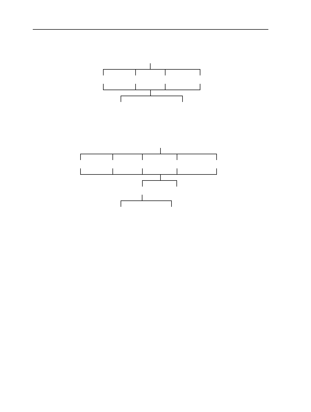
MainStreet Broadband Wireless Technical Practices 27. Alarms
NNP 95-4882-01-00-A Issue 1, April 1999
27-5
DRAFT
To configure the remote alarm queue overflow method
To delete alarms
where
alarm_id is the alarm number listed under the #### column on the screen
alarm1_id is the alarm number (under the #### column) of the first alarm in the range
alarm2_id is the alarm number (under the #### column) of the last alarm in the range
ALARMS — CONFIG — LOG_QUEUE
SK002360
CRITICAL MINORMAJOR DIAGNOSTIC
FIXED CIRCULAR
ALARMS — OUTSTANDING
SK002361
ALL_ALARMSCRITICAL MINORMAJOR DIAGNOSTIC
DELETE_ALLDELETE
<alarm_id1-alarm_id2> ↵<alarm_id> ↵
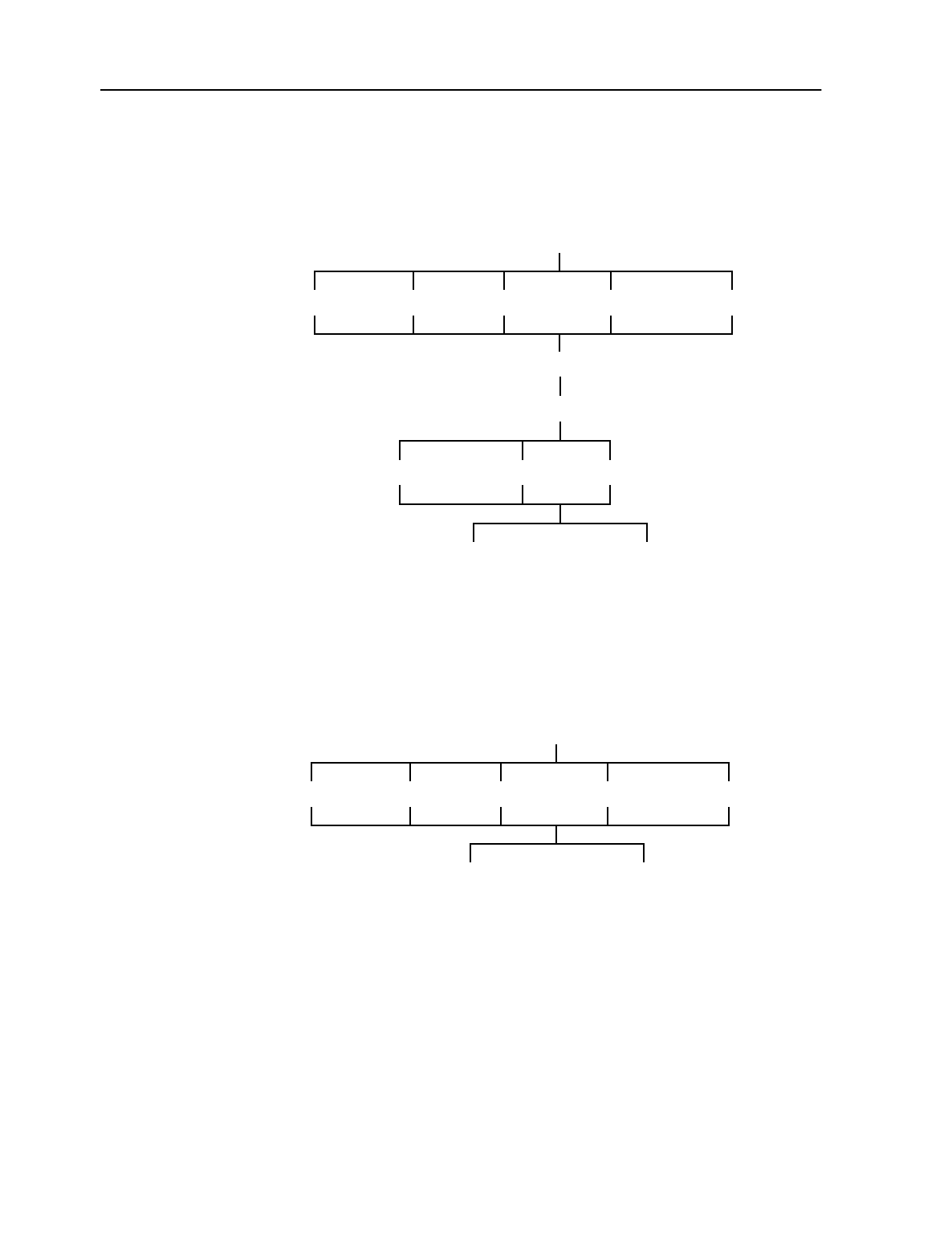
27. Alarms MainStreet Broadband Wireless Technical Practices
Issue 1, April 1999 NNP 95-4882-01-00-A
27-6
DRAFT
To filter the alarm display
The alarm display can be filtered to display outstanding, cleared or all alarms. To
view alarms that have lower alarm numbers, select PAGE_UP. To view alarms that
have higher alarm numbers, select PAGE_DOWN.
To view alarms in a specific queue
To view alarms that have lower alarm numbers, select PAGE_UP. To view alarms that
have higher alarm numbers, select PAGE_DOWN.
ALARMS — OUTSTANDING
SK002362
ALL_ALARMSCRITICAL MINORMAJOR DIAGNOSTIC
PAGE_DOWNPAGE_UP
ALLOUTSTANDING CLEARED
MORE
SUBSET
ALARMS — OUTSTANDING
SK002363
ALL_ALARMSCRITICAL MINORMAJOR DIAGNOSTIC
PAGE_DOWNPAGE_UP

MainStreet Broadband Wireless Technical Practices 27. Alarms
NNP 95-4882-01-00-A Issue 1, April 1999
27-7
DRAFT
To view an alarm summary
Select:
ALARMS
The alarm summary display appears, listing the number of alarms in each of the
alarm queues. For each queue, the display shows the number of outstanding alarms
and the number of total alarms; the alarm total includes cleared alarms and
outstanding alarms.


MainStreet Broadband Wireless Technical Practices 28. Resetting the T-ARIC cards and NIUs
NNP 95-4882-01-00-A Issue 1, April 1999
28-1
DRAFT
28. Resetting the T-ARIC cards and
NIUs
This chapter describes how to reset the following:
• T-ARIC cards and card ports
• 28110 and 28120 MainStreet NIUs and NIU modems
28.1 Resetting a T-ARIC card or port
You can reset both the T-ARIC card and the T-ARIC port.
To reset the T-ARIC card
MAINT — SLOT — <shelf-slot-1> ↵ — RESET_CARD
where
shelf is P1 to P16
slot is an integer from 1 to 11
To reset the T-ARIC card port
MAINT — PORT — <shelf-slot-1> ↵ — RESET_PORT
where
shelf is P1 to P16
slot is an integer from 1 to 11
28.2 Resetting the NIU or NIU modem
You can reset both the 28110 and 28120 MainStreet NIU and the modem.
To reset the NIU
MAINT — SYSTEM — RESET_CARD

28. Resetting the T-ARIC cards and NIUs MainStreet Broadband Wireless Technical Practices
Issue 1, April 1999 NNP 95-4882-01-00-A
28-2
DRAFT
To reset the NIU modem
MAINT — SYSTEM — MODEM — RESET_MODEM

MainStreet Broadband Wireless Technical Practices Glossary
NNP 95-4882-01-00-A Issue 1, April 1999
GL-1
DRAFT
Glossary
0VR zero volts return
AAL ATM-adaptation layer
AIS alarm indication signal
ATM asynchronous transfer mode
BTS base transceiver station
BNC bayonet-locking connector
CBR constant bit rate
CAC connection admission control
CE circuit emulation
CPE customer premises equipment
CPSS control packet switching system
CRC cyclic redundancy check
DS1 digital signal, level 1
DSX-1 digital signal cross-connect, level 1
EMC electromagnetic compatibility
EN european norm
ESF extended superframe format
F(F) Type F connector, female end
F(M) Type F connector, male end
IF intermediate frequency
LED light emitting diode
LIS loss of incoming signal
LO local oscillator
LOF loss of frame
LOS loss of signal
MAU media attachment unit
N(F) Type N connector, female end
N(M) Type N connector, male end

Glossary MainStreet Broadband Wireless Technical Practices
Issue 1, April 1999 NNP 95-4882-01-00-A
GL-2
DRAFT
NIU network interface unit
NMTI node management terminal interface
OAM operations, administration and maintenance
OTU outdoor transmitter unit
OTRU outdoor transmitting and receiving unit
ORU outdoor receiver unit
PSTN public switched telephone network
PVC permanent virtual connection
QoS quality of service
RAI remote alarm indication
RBS robbed bit signaling
RF radio frequency
Rx receive
SNMP simple network management protocol
T-ARIC card Time Division Multiple Access ATM Radio Interface card
TDM time division multiplexing
Tx transmit
VCI virtual channel identifier
VPI virtual path identifier

MainStreet Broadband Wireless Technical Practices Index
NNP 95-4882-01-00-A Issue 1, April 1999
IN-1
DRAFT
Index
28110 MainStreet CE Plus Ethernet T1 NIU, see
T1 NIU, 2-7
28120 MainStreet CE Plus Ethernet E1 NIU, see
E1 NIU, 2-7
A
AAL service type
configuration of, 19-2
E1 NIU, options, 17-1
T1 NIU, options, 17-3
Active LED, 25-2
activity threshold
options, 17-4
add channel
E1 NIU, options, 17-1
T1 NIU, options, 17-3
add channels
configuration of, 21-14
deleting, 21-15
add frequency
E1 NIU, options, 17-1
T1 NIU, options, 17-3
add NIU
about, 21-8
adjustment period
options, 17-4
AIS alarm, 27-1
Alarm LED, 25-2
alarms
acknowledging, 27-3
clearing, 27-3
descriptions, 27-1
local queue overflow, 27-4
logging over CPSS, 27-4
logging over SNMP, 27-4
remote queue overflow, 27-5
antenna
and an OTU or ORU, 5-1
ATM backbone, 1-2
ATM egress data LED, 25-1
ATM ingress data LED, 25-1
B
bandwidth utilization
about, 1-3
Basestation connectivity LED, 25-1
baud rate
E1 NIU, options, 17-1
T1 NIU, options, 17-3
Bias-T
about, 2-13
connecting to Combiner/Splitter, 7-2
connecting to surge protector, 7-1
connectors, 2-13
power cable connections, 9-14
broadband wireless
about, 1-1
ATM-related limitations, 16-2
BTS-related limitations, 16-1
components, 1-1
equipment overview, 2-1
terminology, 1-2
BTScables, 9-1
components, 3-1
mounting hardware, 6-1
simplex and redundant configurations, 3-2
BTS, description of, 1-2
Buffer Overrun alarm, 27-1
Buffer Starvation alarm, 27-1
C
cables
and decibel loss, 9-3
connections, 9-9
types, 9-1
cell, in a wireless network, 1-2
cells discarded by UPC statistics, 23-2, 24-7,
24-8
cells tagged by UPC statistics, 23-2, 24-7, 24-8
cells transmitted statistics, 23-2, 24-7, 24-8
channel bandwidth
about, 21-6
E1 NIU, options, 17-1
T1 NIU, options, 17-3

Index MainStreet Broadband Wireless Technical Practices
Issue 1, April 1999 NNP 95-4882-01-00-A
IN-2
DRAFT
channel frequency
about, 21-6
E1 NIU, options, 17-1
T1 NIU, options, 17-3
channel group name
E1 NIU, options, 17-1
T1 NIU, options, 17-3
channel group number
E1 NIU, options, 17-1
T1 NIU, options, 17-3
channel group range
E1 NIU, options, 17-1
T1 NIU, options, 17-3
channel groups
adding channels to, 18-2
deleting, 18-2
name configuration, 18-2
restrictions on, 18-1
channels
deleting from channel groups, 18-2
channels, number of
E1 NIU options, 17-1
T1 NIU, options, 17-3
Combiner/Splitter
connecting to Bias-T, 7-2
Combiner/Splitter, types, 2-5
contention timeslots
about, 21-12
configuration of, 21-21
options, 17-4
CPE lightning arresters
connecting to grounding plate, 12-1
CRC framing
configuration of, 18-3
E1 NIU, options, 17-1
T1 NIU, 17-3
customer premises equipment
cable loss, 10-2
for dual and single NIU, 10-1
passive components, 10-2
D
data pattern
configuration of, 18-8
deleting channels, 21-15
demodulator
options, 17-4
demodulator status
configuration of, 21-21
Downconverter LO Not Locked alarm, 27-1
downstream channel frequency
about, 21-6
configuration of, 21-19
options, 17-4
downstream channel width
about, 21-6
configuration of, 21-19
options, 17-4
downstream frequency offset
about, 21-3
E1 NIU, options, 17-1
T1 NIU, options, 17-3
downstream IF start frequency
about, 21-6
configuration of, 21-17
options, 17-4
DS1 build out
configuration of, 18-3
options, 17-3
DSX-1 line length
configuration of, 18-4
options, 17-3
E
E1 alarm LED, 25-1
E1 NIU
AAL service type, configuration of, 19-2
AAL service type, options, 17-1
about, 2-7
add channel, options, 17-1
add channels, configuration of, 21-14
add channels, deleting, 21-15
add frequency, options, 17-1
add NIU, about, 21-8
adding to T-ARIC, 21-20
alarms, 27-1
baud rate, options, 17-1
channel bandwidth, about, 21-6
channel bandwidth, options, 17-1
channel frequency, about, 21-6
channel frequency, options, 17-1
channel group name, options, 17-1
channel group number, options, 17-1
channel group range, options, 17-1
channel groups, adding channels to, 18-2
channel groups, deleting, 18-2
channel groups, deleting channels from,
18-2
channel groups, name configuration, 18-2
channel groups, restrictions on, 18-1
channels, number of, options, 17-1
configurable options, 17-1

MainStreet Broadband Wireless Technical Practices Index
NNP 95-4882-01-00-A Issue 1, April 1999
IN-3
DRAFT
CRC framing, configuration of, 18-3
CRC framing, options, 17-1
downstream frequency offset, options, 17-1
E1 port status, 22-1
LED activity, 25-1
LOF alarm clearing time, configuration of,
18-4
LOF alarm clearing time, options, 17-1
LOF alarm declaration time, configuration
of, 18-4
LOF alarm declaration time, options, 17-1
loopbacks, 26-3
NIU basestation connectivity status, 22-1
NIU id, about, 21-8
NIU modem housekeeper link status, 22-1
NIU modem status, 22-1
NIU serial number, about, 21-8
NIU type, about, 21-8
number of channels, about, 21-6
output timing, configuration of, 18-4
output timing, options, 17-1
padding octet value, configuration of, 19-2
padding octet value, options, 17-1
playout buffer, configuration of, 19-3
playout buffer, options, 17-1
port name, configuration of, 18-5
port name, options, 17-1
power level, maximum after network
entry, configuration of, 21-15
power level, maximum before network
entry, configuration of, 21-15
power level, minimum after network
entry, configuration of, 21-16
power level, minimum before network
entry, configuration of, 21-16
power level, options, 17-1
power levels, about, 21-9
removing from T-ARIC, 21-20
serial number, configuration of, 21-24
serial port baud rate, configuration of, 18-6
signaling, options, 17-1
signalling method, configuration of, 18-5
SNMP access communities name,
configuration of, 20-1
SNMP access communities privileges,
configuration of, 20-1
SNMP access communities, deleting, 20-2
SNMP access privileges, options, 17-1
SNMP community name, options, 17-1
SNMP element manager IP address,
options, 17-1
SNMP trap communities element manager
IP address, configuration of, 20-2
SNMP trap communities, configuration of,
20-2
SNMP trap communities, deleting, 20-3
SNMP trap community name, options, 17-1
SNMP trap element manager IP address,
options, 17-1
SNMP trap status, options, 17-1
statistics supported, 23-1, 24-3
status information, 22-1
trunk conditioning code, configuration of,
18-8
trunk conditioning data pattern,
configuration of, 18-8
trunk conditioning data pattern, options,
17-1
trunk conditioning signaling pattern,
options, 17-1
trunk conditioning signalling pattern,
configuration of, 18-8
trunk conditioning, configuration of, 18-7
type, configuration of, 21-25
upstream frequency offset, options, 17-1
user data octets per cell, configuration of,
19-3
user data octets per cell, options, 17-1
E1 port status, 22-1
E1 signal LED, 25-1
Ethernet Activity LED, 25-1
Ethernet Link LED, 25-1
F
framing
configuration of, 18-4
options, 17-3
frequency offsets
downstream frequency offset, 21-3
Rx LO offset, about, 21-3
frequency utilization
about, 1-3
channel bandwidth, about, 21-6
channel frequency, about, 21-6
downstream channel frequency, about,
21-6
downstream channel width, about, 21-6
downstream IF start frequency, about, 21-6
number of channels, about, 21-6
Rx upstream frequency end, about, 21-6
Rx upstream frequency start, about, 21-6
Tx downstream frequency end, 21-7

Index MainStreet Broadband Wireless Technical Practices
Issue 1, April 1999 NNP 95-4882-01-00-A
IN-4
DRAFT
Tx downstream frequency start, about,
21-7
upstream channel frequency, about, 21-7
upstream IF start frequency, about, 21-7
G
group number
options, 17-4
groups
about, 21-8
adding a T-ARIC to, 21-17
removing a T-ARIC from, 21-17
guard timeslots
about, 21-13
configuration of, 21-22
options, 17-4
K
keyboard entries using NMTI, 15-7
L
LED activity
NIU, 25-1
T-ARIC card, 25-2
lightning arresters
connecting to adapter bracket, 8-2
for customer premises equipment, 12-1
function, 2-9
securing to BTS grounding plate, 8-1
limitations
ATM-related, 16-2
BTS-related, 16-1
Line Loopback Activated alarm, 27-1
Link LED, 25-2
LOF alarm, 27-1
LOF alarm clearing time
configuration of, 18-4
E1 NIU, options, 17-1
T1 NIU, options, 17-3
LOF alarm declaration time
configuration of, 18-4
E1 NIU, options, 17-1
T1 NIU, options, 17-3
loopbacks
E1 NIU, 26-3
T1 NIU, 26-3
T-ARIC card, 26-1
LOS alarm, 27-1
M
MainStreetXpress 36170 shelf
and wireless functionality, 1-2
MAU installation, 4-1
MainStreetXpress 45020 Element Manager, 1-2
MainStreetXpress 46020 Network Manager, 1-2
MAU
function, 2-4
installing, 4-1
MAU, see Media Access Unit
Modem Configuration Fault alarm, 27-1
Modem Device alarm, 27-1
N
network registration, 21-9
NIUcommunication flow, illustration of, 1-3
description of, 1-2
downstream channel, illustration of, 1-3
upstream channel, illustration of, 1-4
NIU basestation connectivity status, 22-1
NIU entered network alarm, 27-1
NIU id
about, 21-8
configuration of, 21-20
options, 17-4
NIU Left Network alarm, 27-1
NIU modem housekeeper link status, 22-1
NIU modem status, 22-1
NIU power levels
about, 21-9
NIU serial number
about, 21-8
configuration of, 21-24
options, 17-4
NIU status, 22-1
NIU type
about, 21-8
configuration of, 21-25
options, 17-4
NIU user data VPI
configuration of, 19-4
options, 17-4
NIU, see also E1 NIU
NIU, see also Ethernet NIU
NIU, see also T1 NIU
NMTI
description of, 1-2
initiating a session, 15-1
keyboard entries, 15-7

MainStreet Broadband Wireless Technical Practices Index
NNP 95-4882-01-00-A Issue 1, April 1999
IN-5
DRAFT
level zero, 15-3
main menu, 15-5
overview, 15-1
password, 15-3
screen display, 15-4
session time, 15-3
softkeys, 15-5
number of channels
about, 21-6
O
OAM loopbacks
configuration of, 26-2
types, 26-1
OAM reference point
configuration of, 26-1
options, 17-4
ORU
attaching an antenna, 5-1
function, 2-12
OTRU
alignment to BTS, 14-2
mounting, 11-1
test equipment and components, 14-1
types, 2-14
OTU
attaching an antenna, 5-1
function, 2-12
output timing
configuration of, 18-4
E1 NIU, options, 17-1
T1 NIU, options, 17-3
Over Temperature alarm, 27-1
P
padding octet value
configuration of, 19-2
E1 NIU, options, 17-1
T1 NIU, options, 17-3
password for NMTI, 15-3
playout buffer
configuration of, 19-3
options, 17-1
T1 NIU, options, 17-3
polling timeslots
about, 21-13
configuration of, 21-22
port name
configuration of, 18-5, 21-25
E1 NIU, options, 17-1
options, 17-4
T1 NIU, options, 17-3
power control activity threshold
options, 17-4
power control adjustment period
options, 17-4
power control default power level
configuration of, 21-20
power control maximum power
options, 17-4
power control minimum power
options, 17-4
power control reference NIU
options, 17-4
power control step size
options, 17-4
Power LED, 25-1
power level
E1 NIU, options, 17-1
maximum after network entry,
configuration of, 21-15
maximum before network entry,
configuration of, 21-15
minimum after network entry,
configuration of, 21-16
minimum before network entry,
configuration of, 21-16
T1 NIU, options, 17-3
power level functions
NIU, about, 21-9
R
RAI alarm, 27-1
RAI alarm clearing method
configuration of, 18-4
RBSconfiguration of, 18-6
T1 NIU, options, 17-3
receiver redundancy
see Rx control
red alarm indication alarm clearing
options, 17-3
redundancy
about, 21-10
reference point
options, 17-4
reserved timeslots
options, 17-4
RF downstream frequency end
options, 17-4
RF downstream frequency start
options, 17-4

Index MainStreet Broadband Wireless Technical Practices
Issue 1, April 1999 NNP 95-4882-01-00-A
IN-6
DRAFT
RS-422 cable connections, 9-12
Rx control
about, 21-10
configuration of, 21-17
options, 17-4
Rx LO Not Locked alarm, 27-1
Rx LO offset
about, 21-3
options, 17-4
Rx RF upstream frequency end
options, 17-4
Rx RF upstream frequency start
options, 17-4
Rx upstream end
configuration of, 21-18
Rx upstream frequency end
about, 21-6
Rx upstream frequency start
about, 21-6
Rx upstream start
configuration of, 21-18
S
sector, 1-2
segment loopback, 26-1
serial port
baud rate, configuration of, 18-6
signaling
E1 NIU, options, 17-1
signalling
configuration of, 18-5
signalling pattern
configuration of, 18-8
slot name
options, 17-4
SMA cable connections, 9-13
SNMP access communities
deleting, 20-2
name, configuration of, 20-1
privileges, configuration of, 20-1
SNMP access privileges
E1 NIU, options, 17-1
T1 NIU, options, 17-3
SNMP community name
E1 NIU, options, 17-1
T1 NIU, options, 17-3
SNMP element manager IP address
E1 NIU, options, 17-1
T1 NIU, options, 17-3
SNMP trap communities
configuration of, 20-2
deleting, 20-3
element manager IP address, configuration
of, 20-2
SNMP trap community name
E1 NIU, options, 17-1
T1 NIU, options, 17-3
SNMP trap element manager IP address
E1 NIU, options, 17-1
T1 NIU, options, 17-3
SNMP trap status
E1 NIU, options, 17-1
T1 NIU, options, 17-3
softkeys for NMTI, 15-5
statistics
endpoint, viewing, 23-2, 24-7, 24-8
port, viewing, 23-2
refreshing, 23-2, 24-8
supported, 23-1, 24-3
status information
about, 22-1
Status LED
E1 NIU, 25-1
T1 NIU, 25-1
T-ARIC card, 25-2
surge protector
connecting to Bias-T, 7-1
ground wire, 7-2
surge protectors
function, 2-11
synchronization reference cable
configuration requirements, 9-10
redundant OTU/ORU, 9-11
simplex OTU/ORU, 9-11
System Restart alarm, 27-1
T
T1 alarm LED, 25-1
T1 NIU
AAL service type, configuration of, 19-2
AAL service type, options, 17-3
about, 2-7
add channel, options, 17-3
add channels, configuration of, 21-14
add channels, deleting, 21-15
add frequency, options, 17-3
add NIU, about, 21-8
adding to T-ARIC, 21-20
alarms, 27-1
baud rate, options, 17-3
channel bandwidth, about, 21-6
channel bandwidth, options, 17-3

MainStreet Broadband Wireless Technical Practices Index
NNP 95-4882-01-00-A Issue 1, April 1999
IN-7
DRAFT
channel frequency, about, 21-6
channel frequency, options, 17-3
channel group name, options, 17-3
channel group number, options, 17-3
channel group range, options, 17-3
channel groups, adding channels to, 18-2
channel groups, deleting, 18-2
channel groups, deleting channels from,
18-2
channel groups, name configuration, 18-2
channel groups, restrictions on, 18-1
channels, number of, options, 17-3
CRC framing, configuration of, 18-3
CRC framing, options, 17-3
downstream frequency offset, 17-3
DS1 build out, configuration of, 18-3
DS1 build out, options, 17-3
DSX-1 line length, configuration of, 18-4
DSX-1 line length, options, 17-3
framing, configuration of, 18-4
framing, options, 17-3
LED activity, 25-1
LOF alarm clearing time, configuration of,
18-4
LOF alarm clearing time, options, 17-3
LOF alarm declaration time, configuration
of, 18-4
LOF alarm declaration time, options, 17-3
loopbacks, 26-3
NIU basestation connectivity status, 22-1
NIU id, about, 21-8
NIU modem housekeeper link status, 22-1
NIU modem status, 22-1
NIU serial number, about, 21-8
NIU type, about, 21-8
number of channels, about, 21-6
output timing, configuration of, 18-4
output timing, options, 17-3
padding octet value, configuration of, 19-2
padding octet value, options, 17-3
playout buffer, configuration of, 19-3
playout buffer, options, 17-3
port name, configuration of, 18-5
port name, options, 17-3
power level, maximum after network
entry, configuration of, 21-15
power level, maximum before network
entry, configuration of, 21-15
power level, minimum after network
entry, configuration of, 21-16
power level, minimum before network
entry, configuration of, 21-16
power level, options, 17-3
power levels, about, 21-9
RAI alarm clearing method, configuration
of, 18-4
RBS, configuration of, 18-6
RBS, options, 17-3
red alarm indication alarm clearing,
options, 17-3
removing from T-ARIC, 21-20
serial number, configuration of, 21-24
serial port baud rate, configuration of, 18-6
signaling, options, 17-3
SNMP access communities name,
configuration of, 20-1
SNMP access communities privileges,
configuration of, 20-1
SNMP access communities, deleting, 20-2
SNMP access privileges, options, 17-3
SNMP community name, options, 17-3
SNMP element manager IP address,
options, 17-3
SNMP trap communities element manager
IP address, configuration of, 20-2
SNMP trap communities, configuration of,
20-2
SNMP trap communities, deleting, 20-3
SNMP trap community name, options, 17-3
SNMP trap element manager IP address,
options, 17-3
SNMP trap status, options, 17-3
statistics supported, 23-1, 24-3
status information, 22-1
T1 port status, 22-1
trunk conditioning code, configuration of,
18-8
trunk conditioning data pattern,
configuration of, 18-8
trunk conditioning data pattern, options,
17-3
trunk conditioning signalling pattern,
configuration of, 18-8
trunk conditioning signalling pattern,
options, 17-3
trunk conditioning, configuration of, 18-7
type, configuration of, 21-25
upstream frequency offset, options, 17-3
user data octets per cell, configuration of,
19-3
user data octets per cell, options, 17-3
zero suppression method, configuration of,
18-5
zero suppression, options, 17-3

Index MainStreet Broadband Wireless Technical Practices
Issue 1, April 1999 NNP 95-4882-01-00-A
IN-8
DRAFT
T1 port status, 22-1
T1 signal LED, 25-1
T-ARIC
card type, about, 21-11
card type, configuration of, 21-25
contention timeslots, about, 21-12
contention timeslots, configuration of,
21-21
demodulator status, configuration of, 21-21
downstream channel frequency, about,
21-6
downstream channel frequency,
configuration of, 21-19
downstream channel width, about, 21-6
downstream channel width, configuration
of, 21-19
downstream IF start frequency, about, 21-6
downstream IF start frequency,
configuration of, 21-17
endpoint statistics, viewing, 23-2, 24-7, 24-8
groups, about, 21-8
groups, adding to, 21-17
groups, removing from, 21-17
guard timeslots, about, 21-13
guard timeslots, configuration of, 21-22
guard timeslots, options, 17-4
NIU serial number, configuration of, 21-24
NIU status, 22-1
NIU type, configuration of, 21-25
NIU user data VPI, configuration of, 19-4
NIU, adding, 21-20
NIU, removing, 21-20
polling timeslots, about, 21-13
polling timeslots, configuration of, 21-22
port name, configuration of, 21-25
port statistics, viewing, 23-2
port status, 22-1
power control default power level,
configuration of, 21-20
redundancy, about, 21-10
Rx control, about, 21-10
Rx control, configuration of, 21-17
Rx upstream end, configuration of, 21-18
Rx upstream frequency end, about, 21-6
Rx upstream frequency start, about, 21-6
Rx upstream start, configuration of, 21-18
slot name, about, 21-11
slot name, configuration of, 21-26
slot status, 22-1
statistics supported, 23-1, 24-3
statistics, refreshing, 23-2, 24-8
status information, 22-1
tuner module status, 22-1
Tx control, about, 21-10
Tx control, configuration of, 21-17
Tx downstream end, configuration of,
21-18
Tx downstream frequency end, about, 21-7
Tx downstream frequency start, about,
21-7
Tx downstream start, configuration of,
21-18
UBR timeslots, about, 21-13
UBR timeslots, configuration of, 21-23
upstream channel frequency, about, 21-7
upstream channel frequency,
configuration of, 21-24
upstream IF start frequency, about, 21-7
upstream IF start, configuration of, 21-18
T-ARIC card
about, 2-2
activity threshold, options, 17-4
adjustment period, options, 17-4
alarms, 27-1
communication flow, illustration of, 1-3
connectors, 2-3
contention timeslots, options, 17-4
demodulator, options, 17-4
description of, 1-2
downstream channel frequency, options,
17-4
downstream channel width, options, 17-4
downstream channel, illustration of, 1-3
downstream IF start frequency, options,
17-4
group number, options, 17-4
LED activity, 25-2
loopbacks, 26-1
NIU id, options, 17-4
NIU serial number, options, 17-4
NIU type, options, 17-4
NIU user data VPI, options, 17-4
OAM loopback, 26-2
OAM reference point, 26-1
OAM reference point, options, 17-4
OAM segment loopback, 26-2
port name, options, 17-4
power control activity threshold, options,
17-4
power control adjustment period, options,
17-4
power control maximum power, options,
17-4

MainStreet Broadband Wireless Technical Practices Index
NNP 95-4882-01-00-A Issue 1, April 1999
IN-9
DRAFT
power control minimum power, options,
17-4
power control reference NIU, options, 17-4
power control step size, options, 17-4
reference point, options, 17-4
reserved timeslots, options, 17-4
RF downstream frequency end, options,
17-4
RF downstream frequency start, options,
17-4
Rx control, options, 17-4
Rx LO offset, options, 17-4
Rx RF upstream frequency end, options,
17-4
Rx RF upstream frequency start, options,
17-4
slot name, options, 17-4
timeslots reserved for NIUs, options, 17-4
timeslots reserved for guard slots, options,
17-4
timeslots reserved for NIU contention,
options, 17-4
Tx control, options, 17-4
Tx interface power level, options, 17-4
Tx power level status, options, 17-4
Tx power level, options, 17-4
upstream channel frequency, options, 17-4
upstream channel, illustration of, 1-4
upstream IF start, options, 17-4
VCI, options, 17-4
VPI, options, 17-4
T-ARIC group
description of, 1-2
T-ARIC port status, 22-1
T-ARIC slot status, 22-1
terminology, for wireless components, 1-2
timeslots reserved for Ethernet NIUs
options, 17-4
timeslots reserved for guard slots
options, 17-4
timeslots reserved for NIU contention
options, 17-4
transceiver, see OTRU 2-14
transmitter redundancy
see Tx control
trunk conditioning
configuration of, 18-7
trunk conditioning code
configuration of, 18-8
trunk conditioning data pattern
configuration of, 18-8
E1 NIU, options, 17-1
T1 NIU, options, 17-3
trunk conditioning signaling pattern
E1 NIU, options, 17-1
T1 NIU, options, 17-3
trunk conditioning signalling pattern
configuration of, 18-8
TS16 AIS alarm, 27-1
TS16 Multiframe alarm, 27-1
TS16 RAI alarm, 27-1
tuner module status, 22-1
Tx control
about, 21-10
configuration of, 21-17
options, 17-4
Tx downstream end
configuration of, 21-18
Tx downstream frequency end
about, 21-7
Tx downstream frequency start
about, 21-7
Tx downstream start
configuration of, 21-18
Tx interface power level
options, 17-4
Tx LO not locked alarm, 27-1
Tx power level
options, 17-4
Tx power level status
options, 17-4
U
UBR timeslots
about, 21-13
configuration of, 21-23
Upconverter LO Not Locked alarm, 27-1
upstream channel frequency
about, 21-7
configuration of, 21-24
options, 17-4
upstream frequency offset
E1 NIU, options, 17-1
T1 NIU, options, 17-3
upstream IF start
configuration of, 21-18
options, 17-4
upstream IF start frequency
about, 21-7
upstream timeslot utilization
contention timeslots, about, 21-12
guard timeslots, about, 21-13
polling timeslots, about, 21-13

Index MainStreet Broadband Wireless Technical Practices
Issue 1, April 1999 NNP 95-4882-01-00-A
IN-10
DRAFT
UBR timeslots, about, 21-13
user data octets per cell
configuration of, 19-3
E1 NIU, options, 17-1
T1 NIU, options, 17-3
V
valid cells received statistics, 23-2, 24-7, 24-8
VCIoptions, 17-4
verifying the shipment, 13-1
VPINIU user data VPI, configuration of, 19-4
options, 17-4
Z
zero suppression
configuration of, 18-5
options, 17-3


Corporate Headquarters
Newbridge Networks Corporation
600 March Road, P.O. Box 13600
Kanata, Ontario, Canada K2K 2E6
Telephone: +1 613 591 3600
Facsimile: +1 613 591 3680
North and South America
Newbridge Networks Inc.
593 Herndon Parkway
Herndon, Virginia U.S.A. 20170-5241
Telephone: 1 800 343 3600
+1 703 834 3600
Facsimile: +1 703 471 7080
Europe, Middle East and Africa
Newbridge Networks Limited
Coldra Woods, Chepstow Road
Newport, South Wales NP6 1JB U.K.
Telephone: +44 (0) 1633 413600
Facsimile: +44 (0) 1633 413680
Asia Pacific
Newbridge Networks Sdn.Bhd.
Unit 1201 Level 12, Uptown Two
2, Jalan SS 21/37
Damansara Uptown
47400 Petaling Jaya
Selangor Darul Ehsan, Malaysia
Telephone: +60 3 715 8400
Facsimile: +60 3 715 8415
Printed in Canada
90-4434-01
Newbridge and logo, and MainStreet are registered
trademarks of Newbridge Networks Corporation.
All other trademarks are property of their respective
holders.
Information subject to change without notice.
© 1999 Newbridge Networks Corporation.
All rights reserved.