Alcatel Lucent USA CMP-40 Cellular Base Station Transceiver User Manual users manual 1
Alcatel-Lucent USA Inc. Cellular Base Station Transceiver users manual 1
UserManual.wiki
>
Alcatel Lucent USA
>
CMP-40 User Manual
>
users manual 1
Contents
1.
users manual 1
2.
users manual 2
3.
users manual 3
users manual 1
Navigation menu
Upload a User Manual
Namespaces
Wiki Guide
HTML
PDF
Info
Views
User Manual
Discussion / Help
Navigation


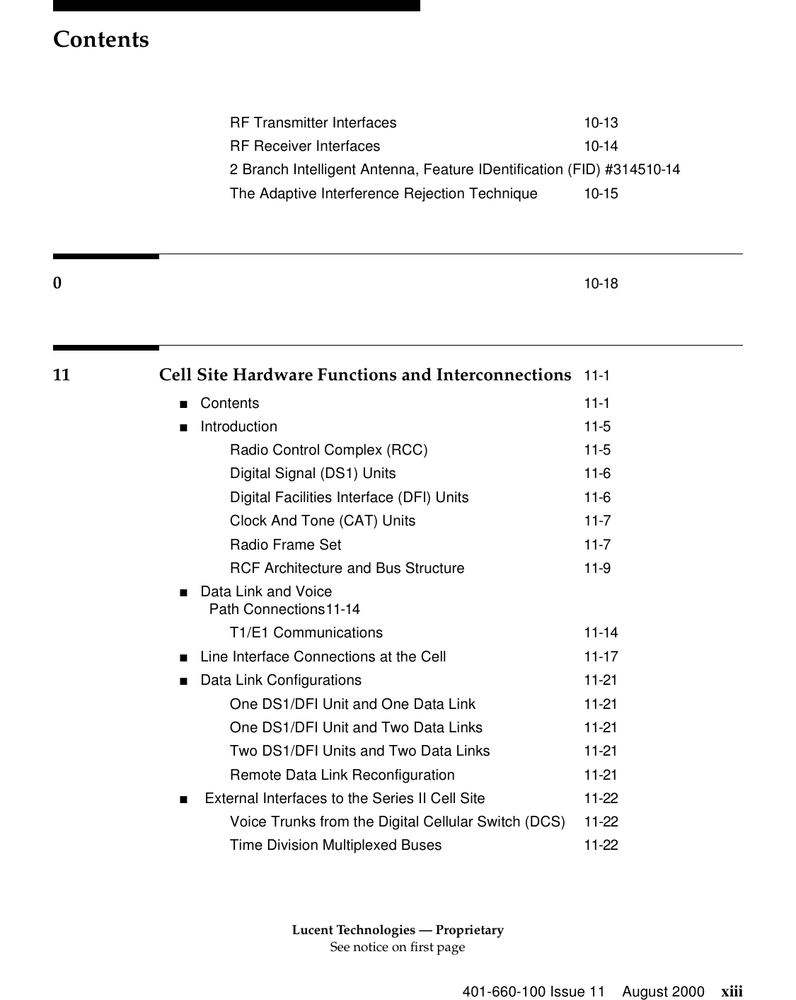
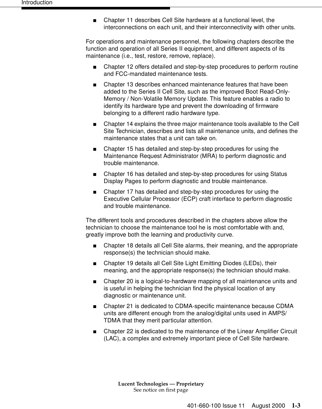


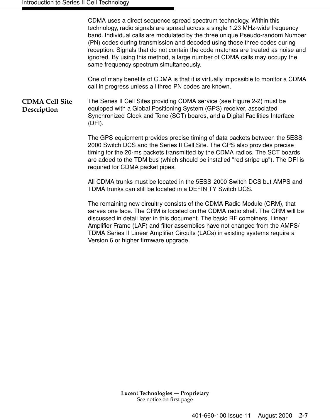
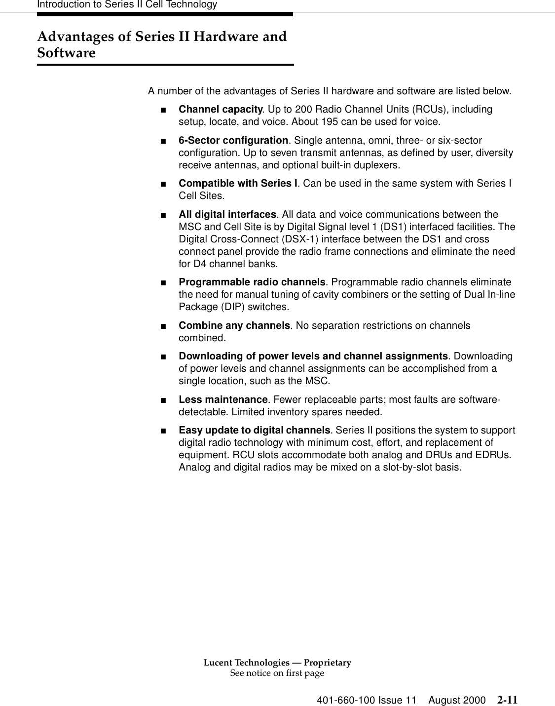
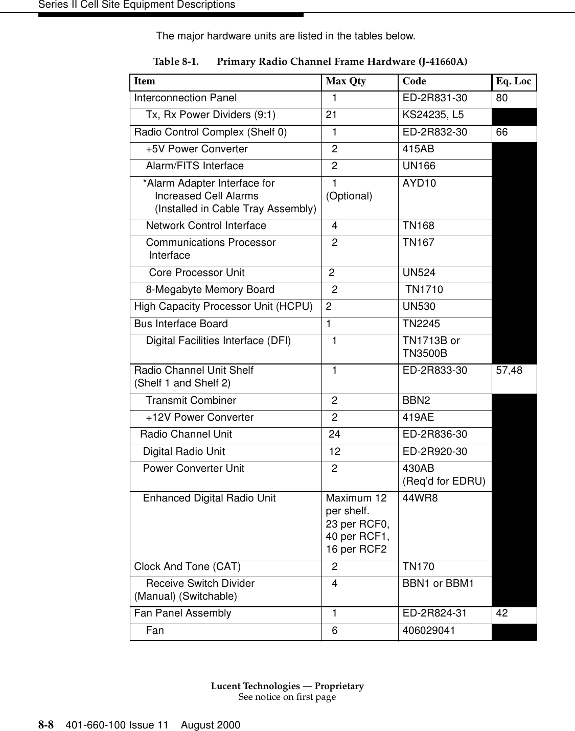
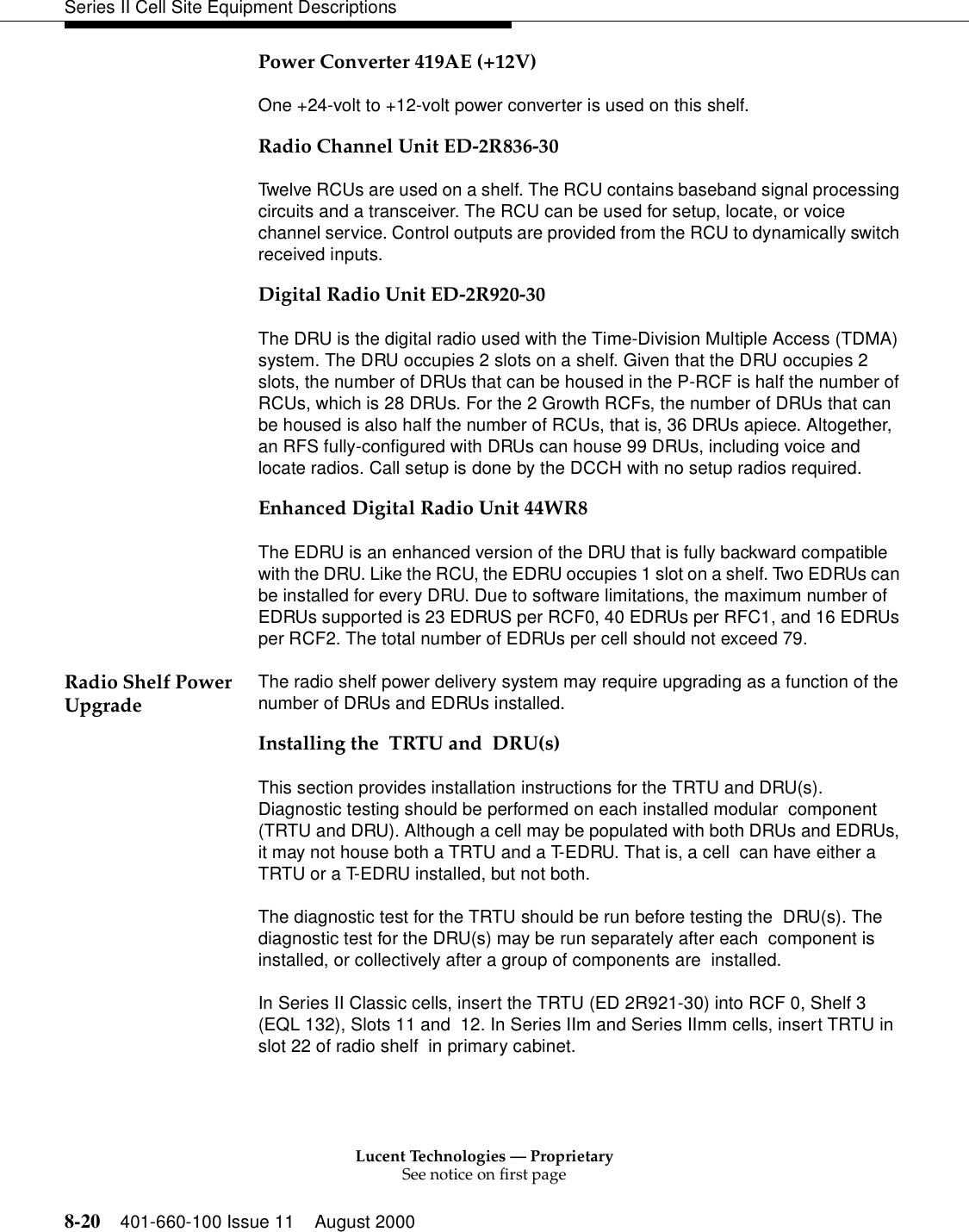
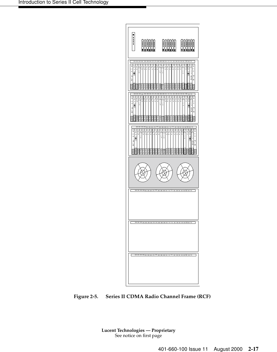
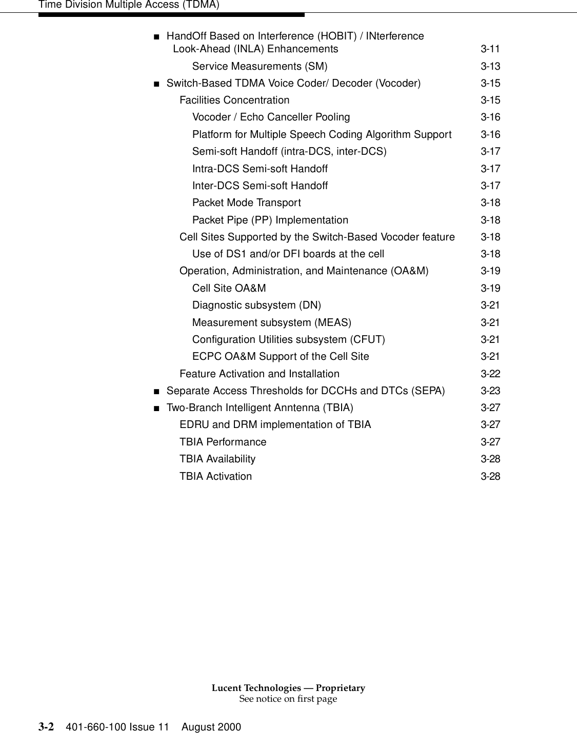
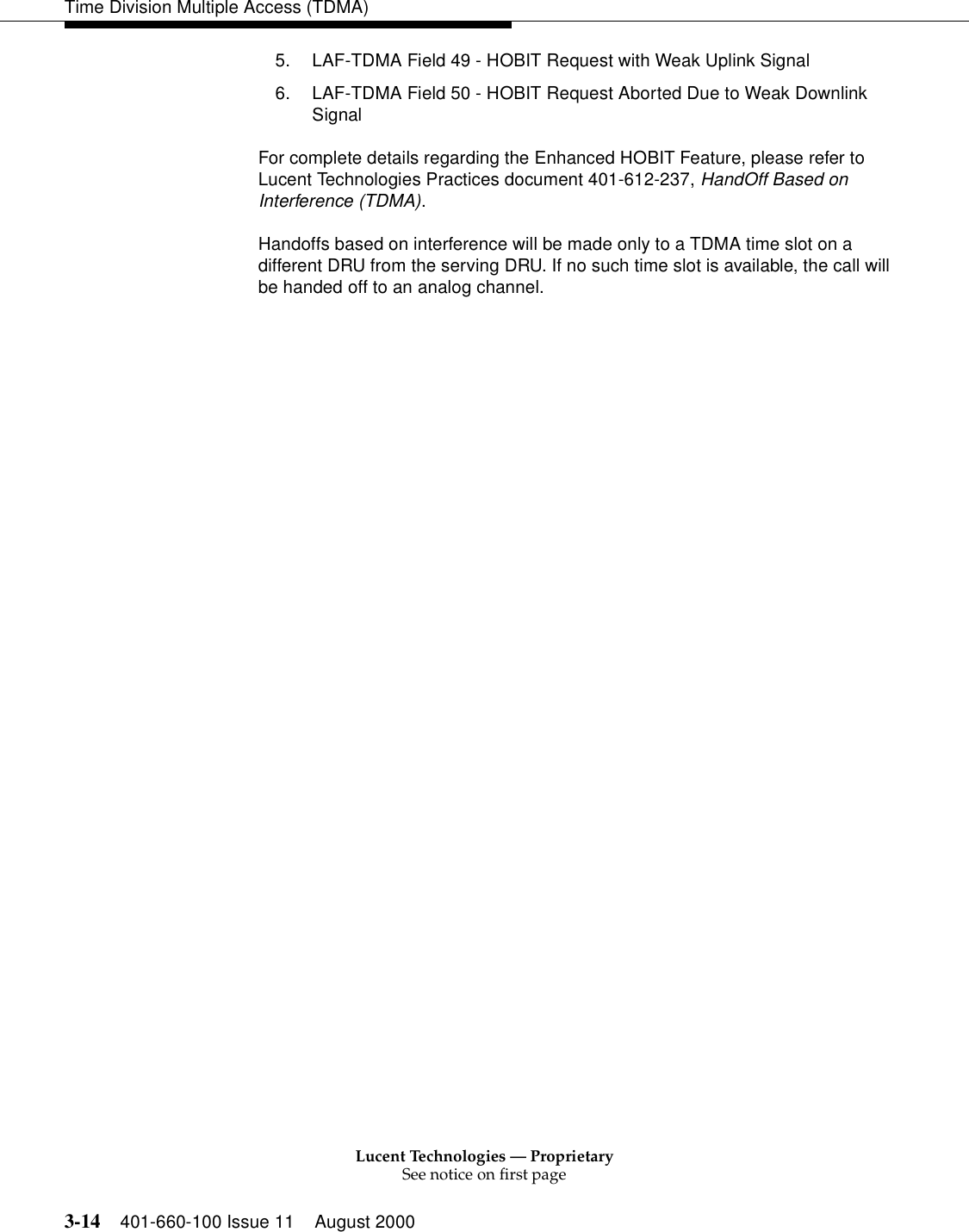
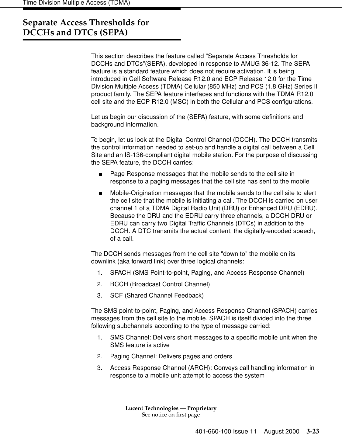
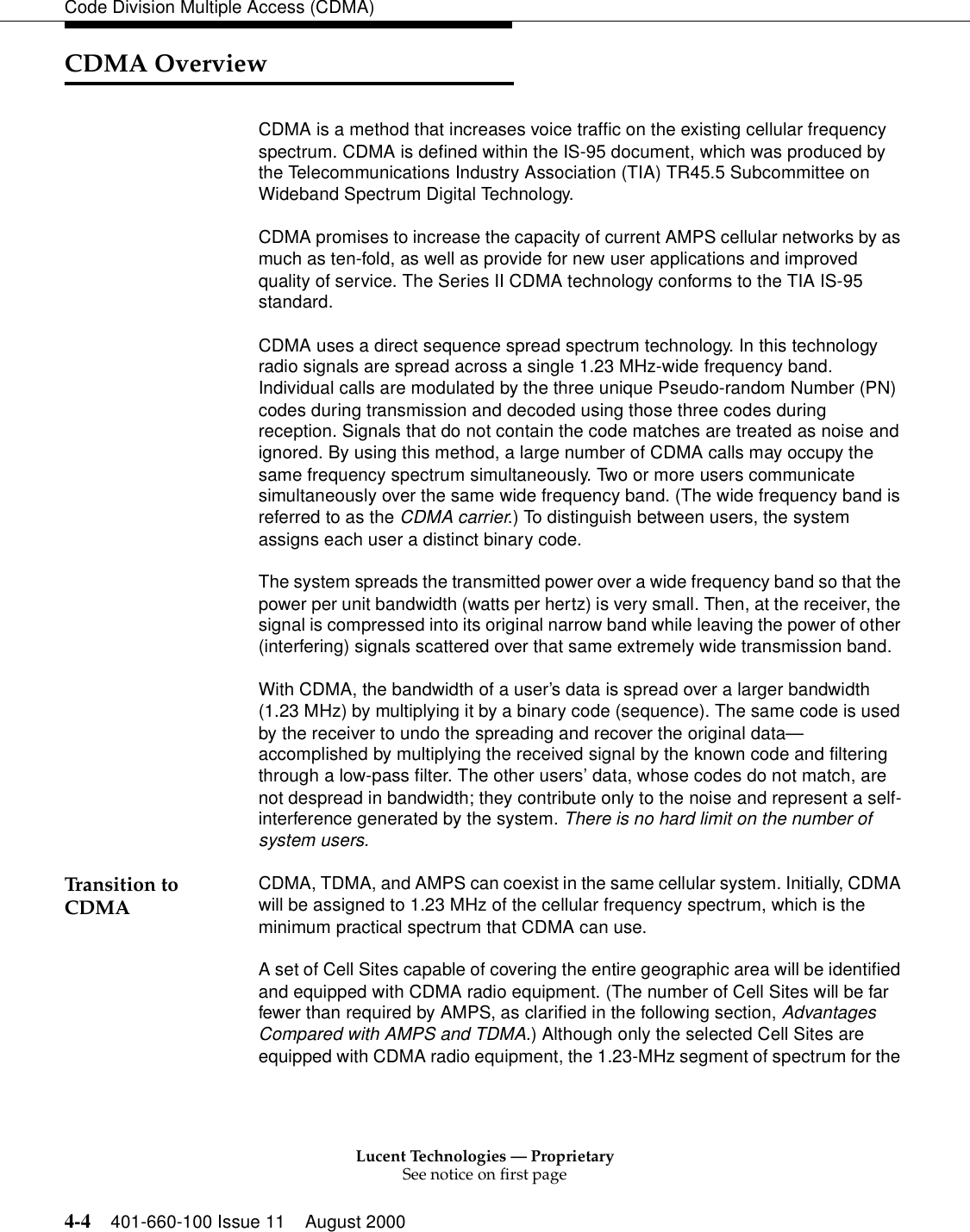
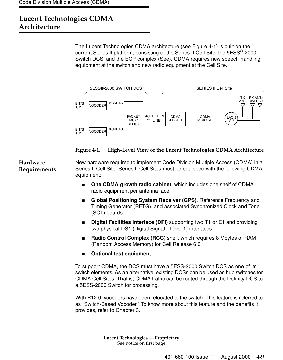
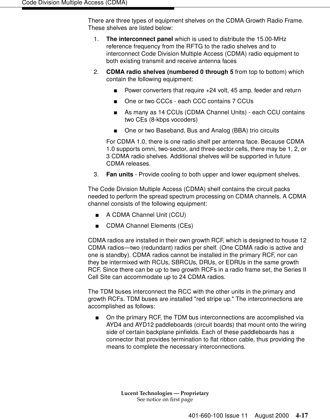
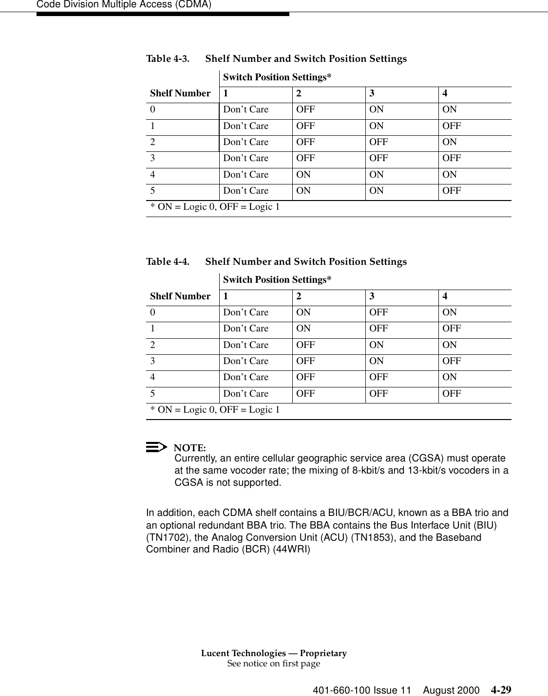
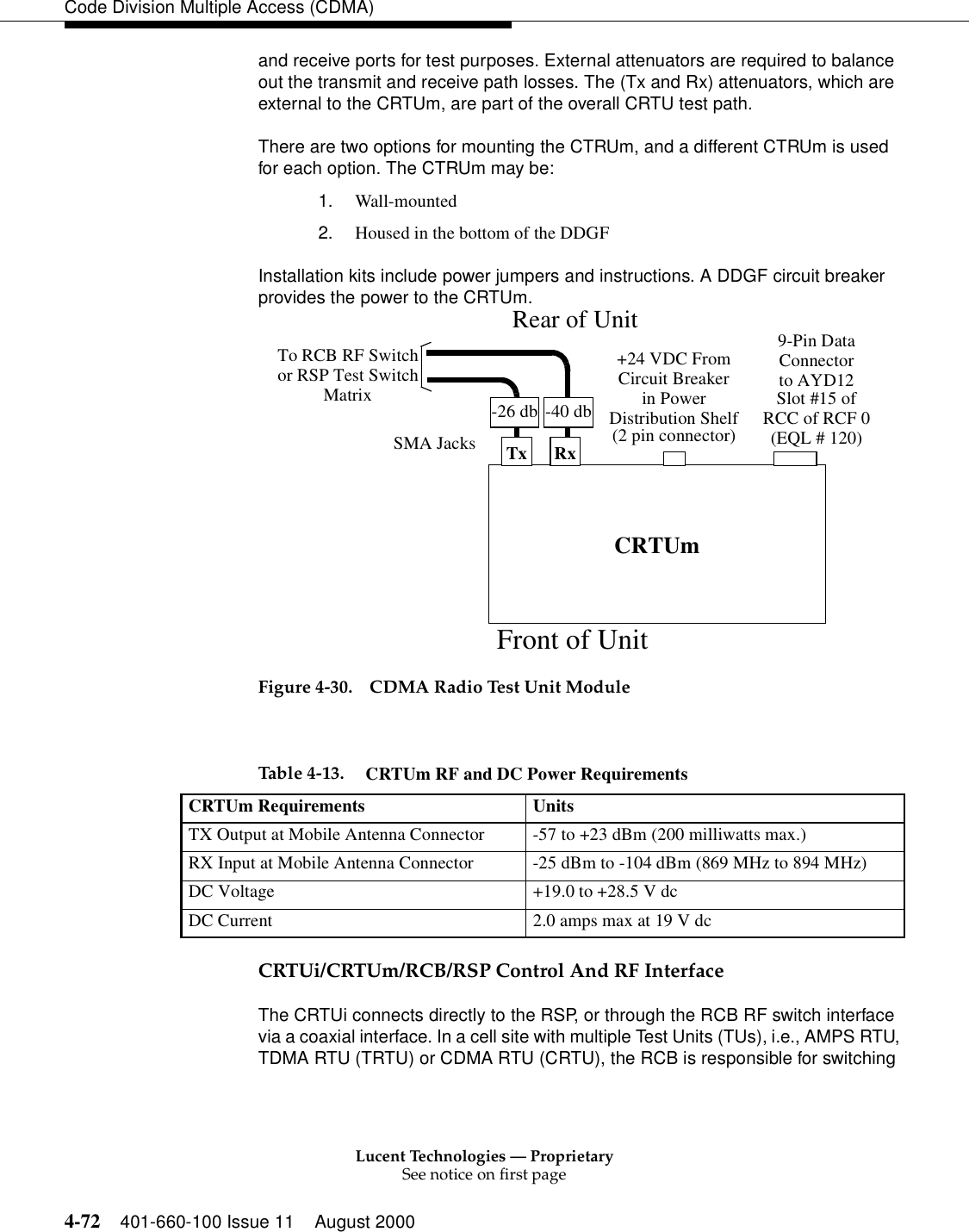
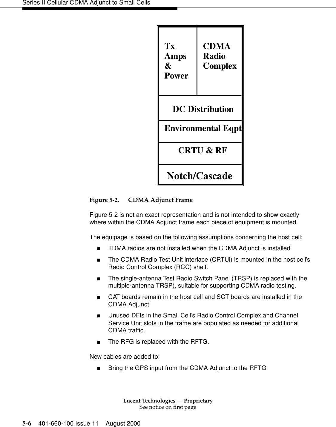
![Lucent Technologies — ProprietarySee notice on first page401-660-100 Issue 11 August 2000 2-13Introduction to Series II Cell Technology■Optical Interface Frame J41660H-1 Figure 2-3. Cell Site ArchitectureRadio Channel Frames and Radio Equipment Functional OverviewThe radio frame set (Figure 2-4) consists of a primary RCF and up to two growth RCFs connected by one or two Time-Division Multiplexed (TDM) buses (which should be installed "red stripe up") and controlled by the primary RCF. The primary RCF is unique in that it contains the Cell Site controller (the Radio Control Complex [RCC]) on the uppermost shelf (shelf 0) in addition to five radio shelves below (shelves 1 through 5).VoiceTrunksandDataLinksRFRadio Frame SetRFRFDS1InputsRadioChannelFrame 0(Optional)LinearAmplifierFrame 0FacilitiesInterfaceFrameRadioChannelFrame 1RadioChannelFrame 2LinearAmplifierFrame 1(Includes RadioControlComplex)(Optional)AntennaInterfaceFrame 0AntennaInterfaceFrame 1RX0 RX 1TX Primary Growth Growth(RCF0)(RCF1)(RCF2)(LAF0)(LAF1)(AIF0)(AIF1)(FIF)(High-PowerAntennas)((Optional) (Optional)](https://usermanual.wiki/Alcatel-Lucent-USA/CMP-40.users-manual-1/User-Guide-161958-Page-58.png)


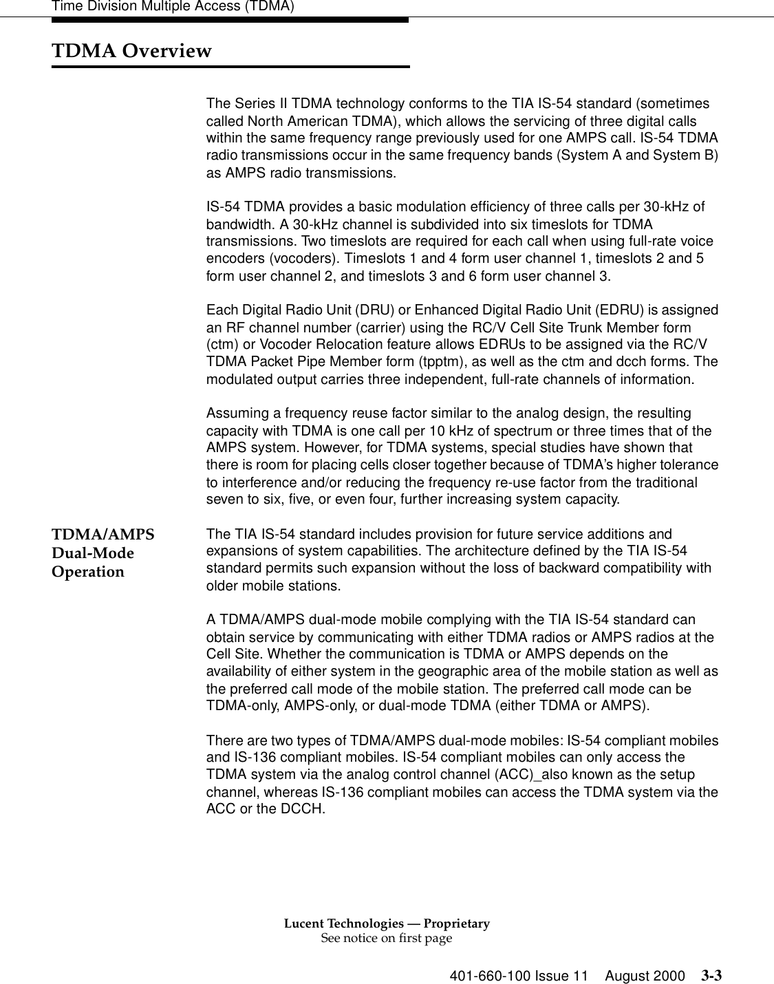
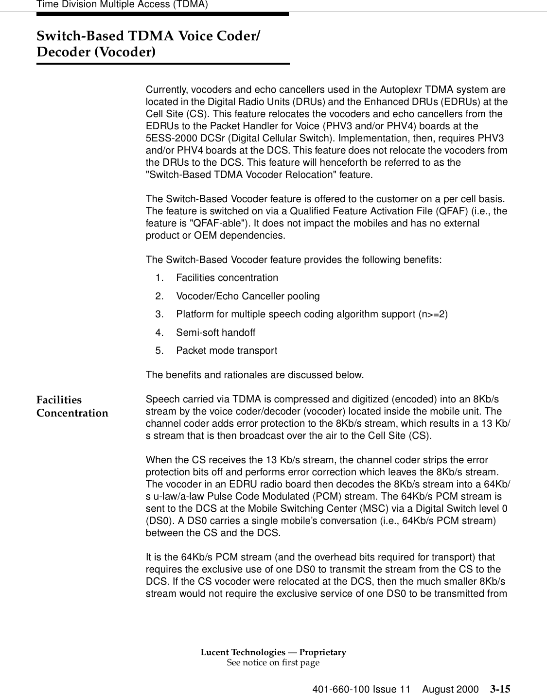
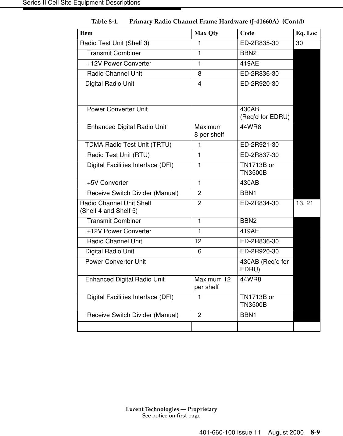
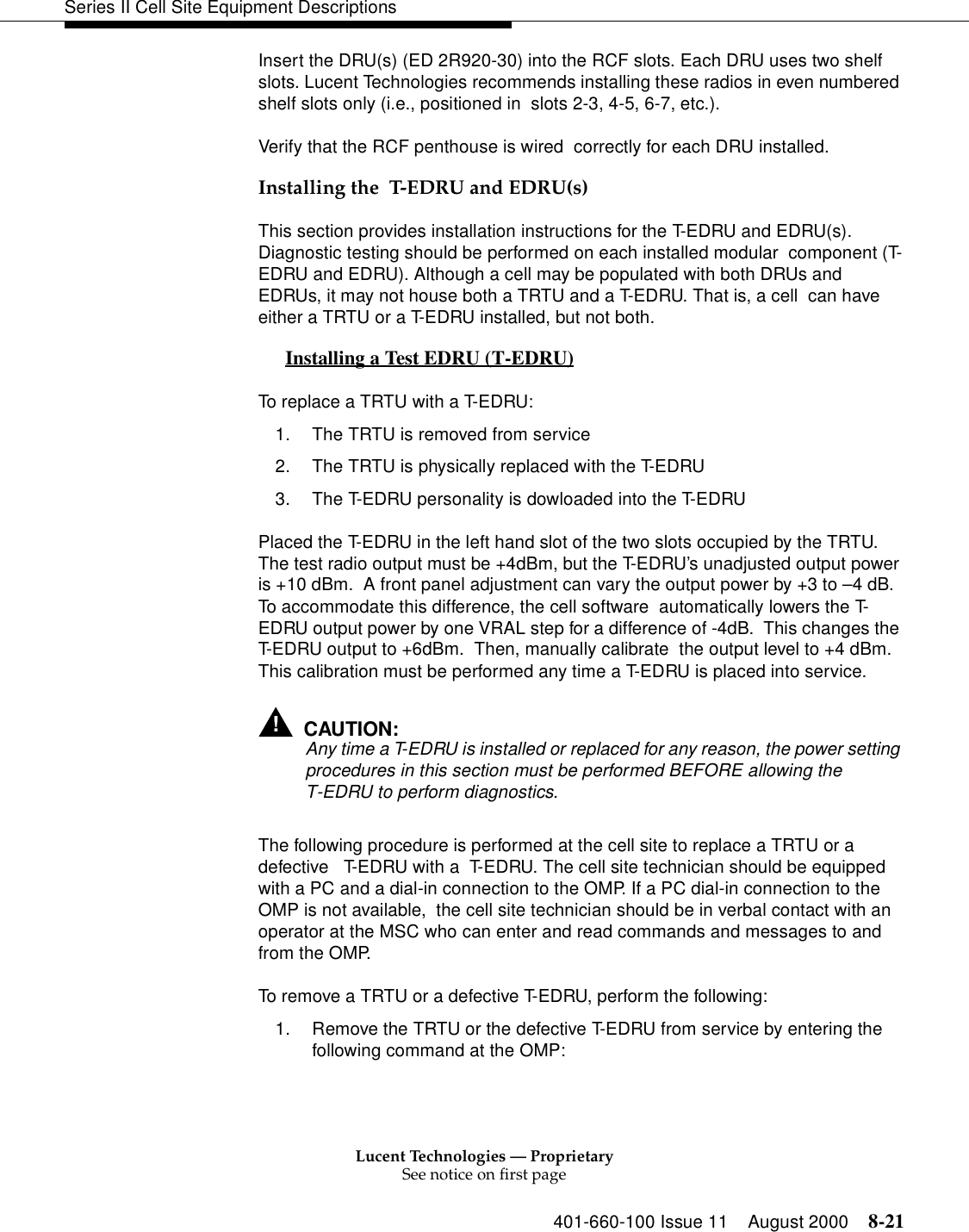
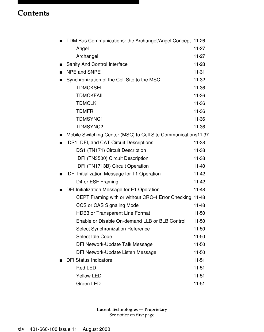
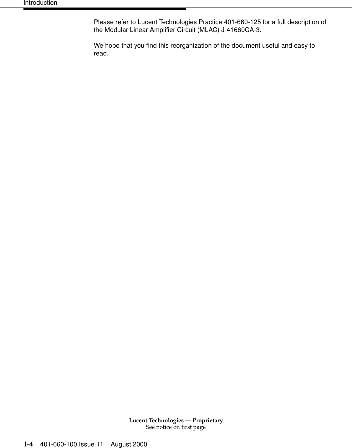
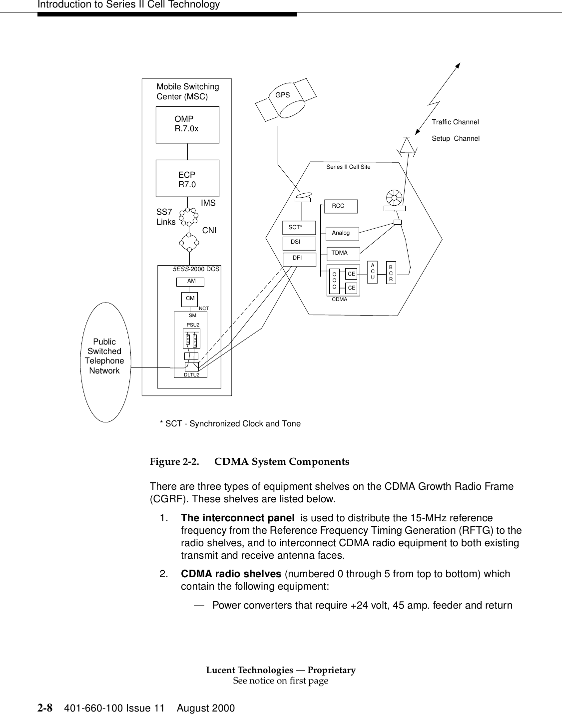
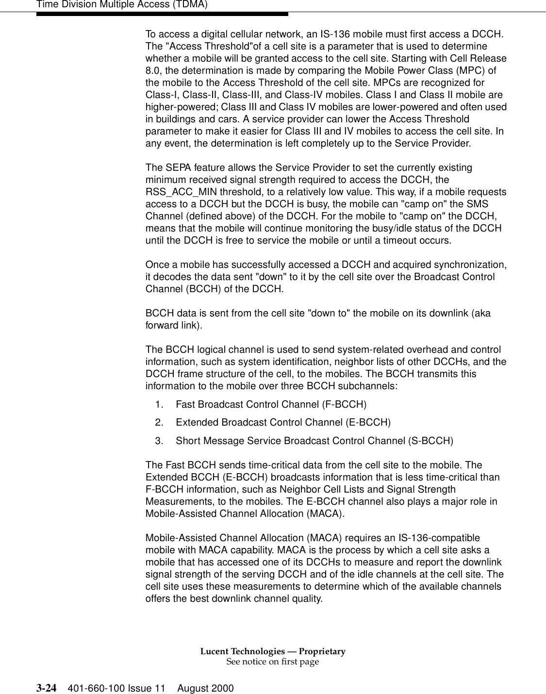
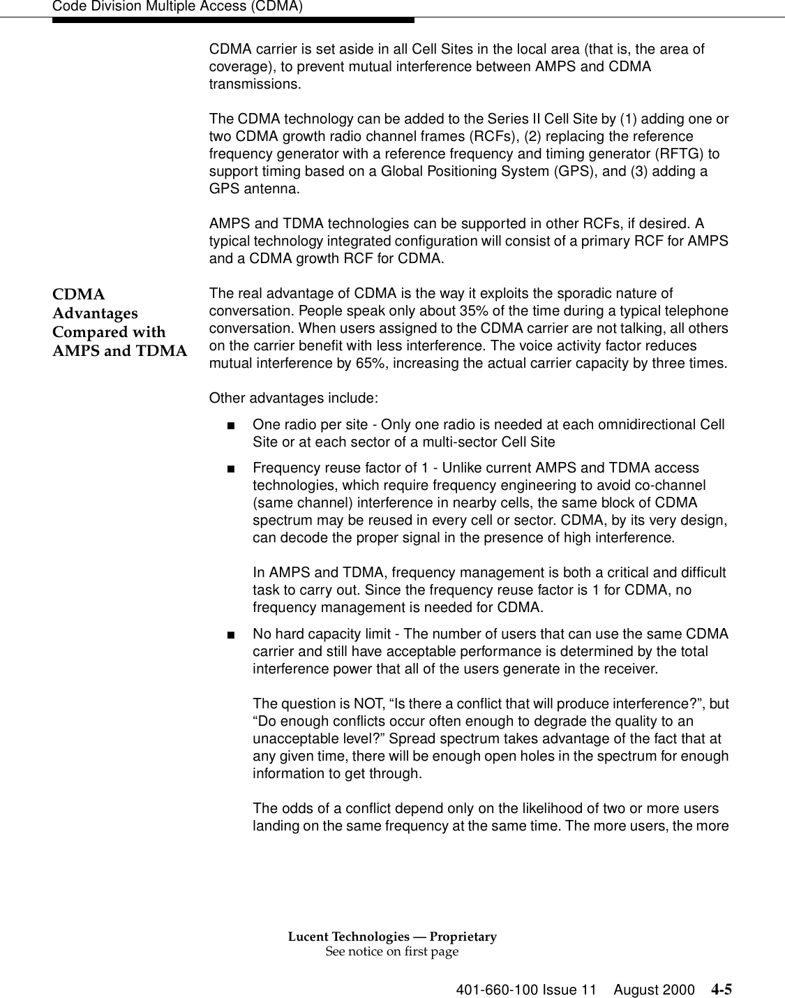
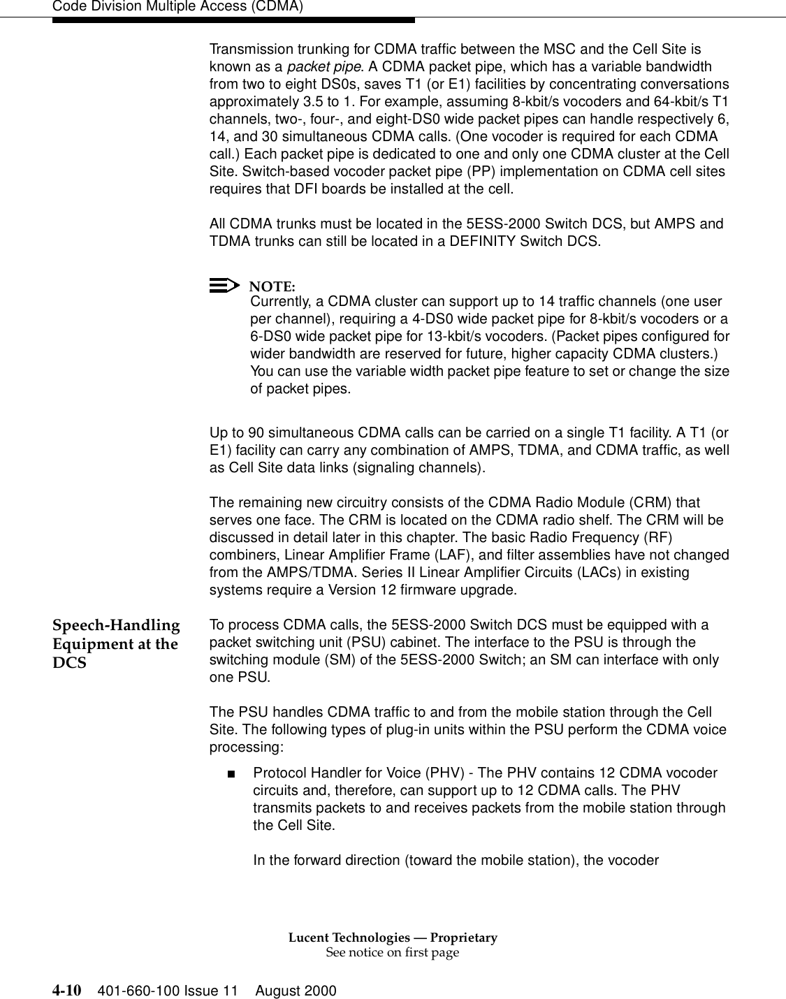
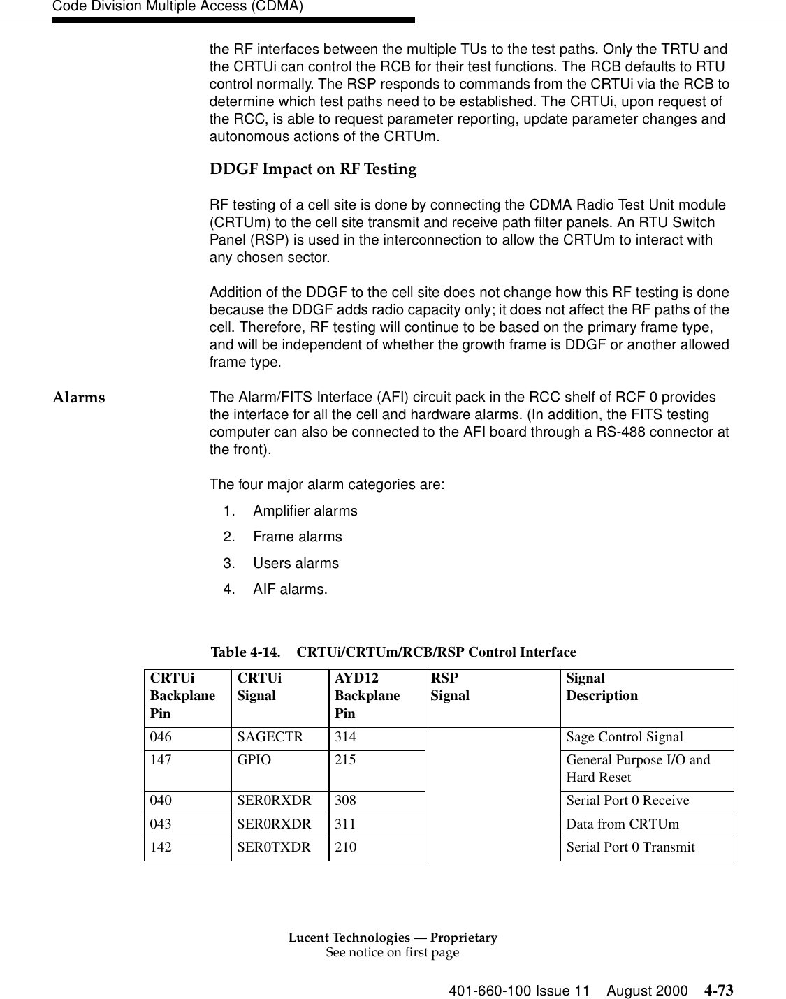
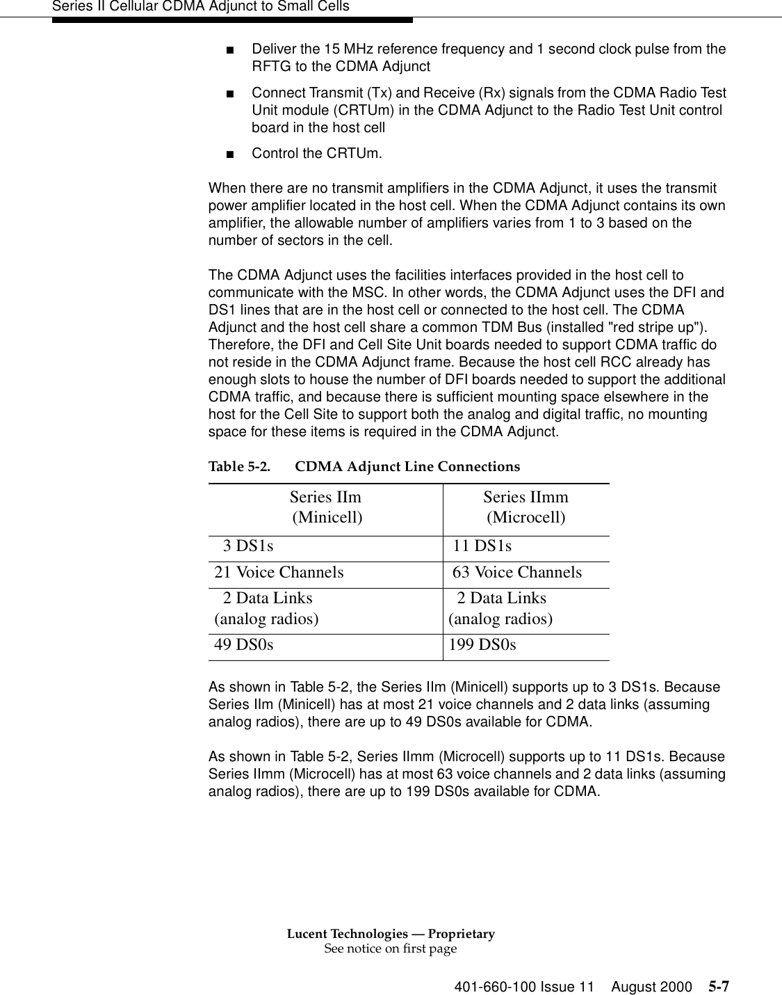
![Lucent Technologies — ProprietarySee notice on first page3-20 401-660-100 Issue 11 August 2000Time Division Multiple Access (TDMA)The Maintenance Request Administrator (MRA) at the Radio Control Complex (RCC) continues to handle all such maintenance requests (i.e., remove, restore, diagnostics). Those translations in the RCC have been updated to check and report the status of PP trunks, in addition to the status of pre-existing trunks. Maintaining PP status allows the RCC to take appropriate action for any maintenance requested on a PP. Therefore, a CS with a mixture of DRUs and EDRUs, and with the Switch-Based Vocoder feature implemented, continues to support all the OA&M of pre-existing trunks as well as that of the new PPs. The RCC also supports both technician-initiated and autonomous maintenance actions requested for a PP. Additionally, the RCC/EDRU detects and reports any PP failure(s) back to the ECPC (i.e. transmit identification [XID] packets are not received in time, voice packets do not arrive when expected, etc.). The CS receives, recognizes, and acts on PP status messages received from the ECPC. For CS EDRUs for which the vocoder has been relocated at the DCS, vocoder-specific OA&M has been disabled and all other OA&M functionality remains. EDRU testing that requires a vocoder has been re-implemented to be independent of the need to have a vocoder at the CS. The following radio-related OA&M subsystems that reside in the Radio Control Complex (RCC) have been redesigned: Configuration Utilities (CFUT) Diagnostics (DN) Measurement (MEAS) These subsystems, which operate within the CS, have been redesigned because certain functions performed by the Vocoder no longer exist in every EDRU. In particular, for those EDRUs whose vocoders have been moved to the DCS, there are: ■No Vocoder MUTE/UNMUTE settings■No Vocoder Tx/Rx Gain settings■No Vocoder Tx Tones generatedThe only EDRU-specific Diagnostic test impacted by the Switch-Based Vocoder feature is the Baseband Transmission Level test. Voice-band tests include the Baseband Transmission Level Test of the DN subsystem and Audio Level Measurements of the MEAS subsystem. The MEAS subsystem performs Audio Level Measurements in both Transmit (Tx) and Receive (Rx) directions. Voice-band tests use a Clock And Tone (CAT) board to generate and detect a tone, and a TDMA Radio Test Unit (TRTU) to emulate a mobile phone.](https://usermanual.wiki/Alcatel-Lucent-USA/CMP-40.users-manual-1/User-Guide-161958-Page-85.png)
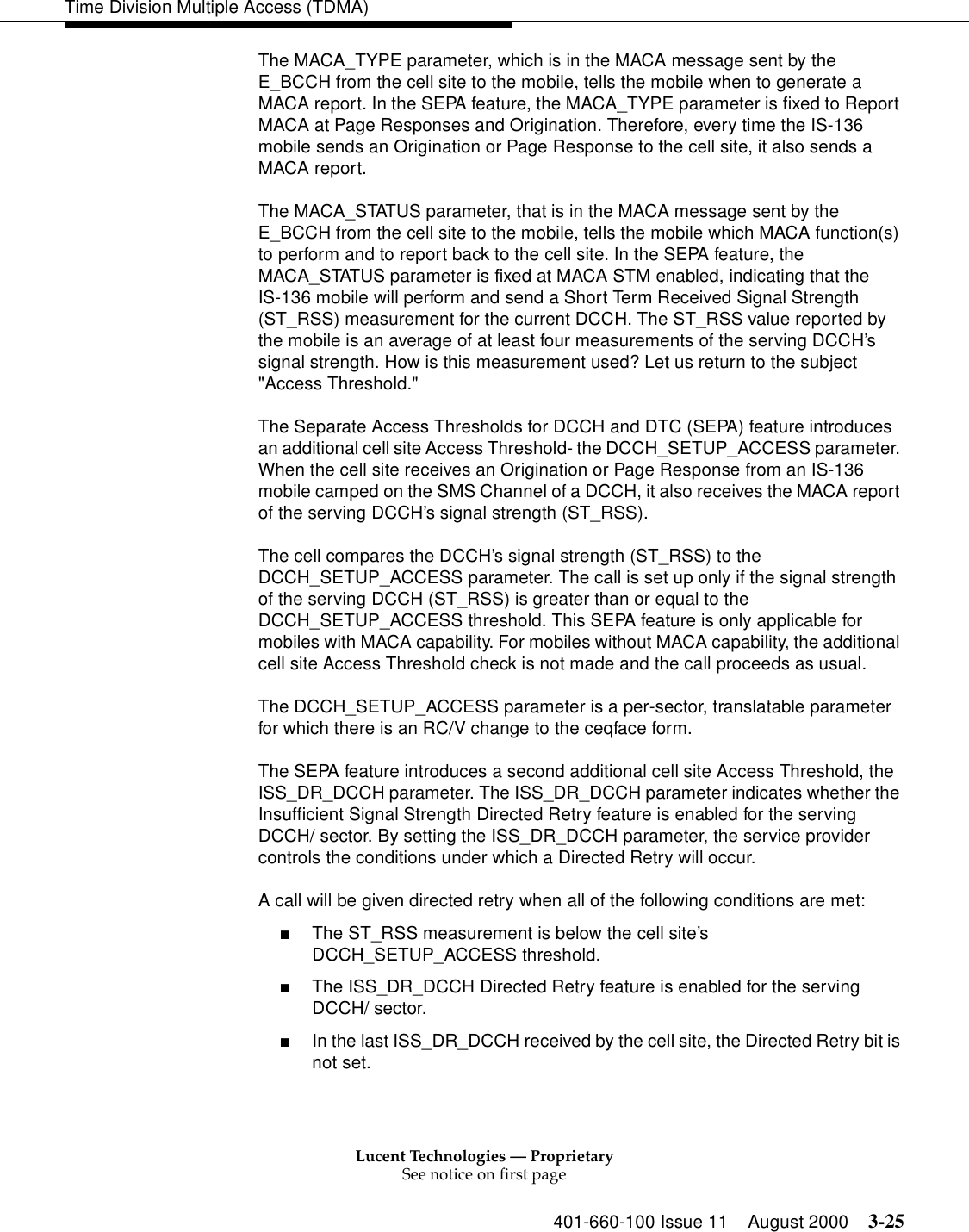


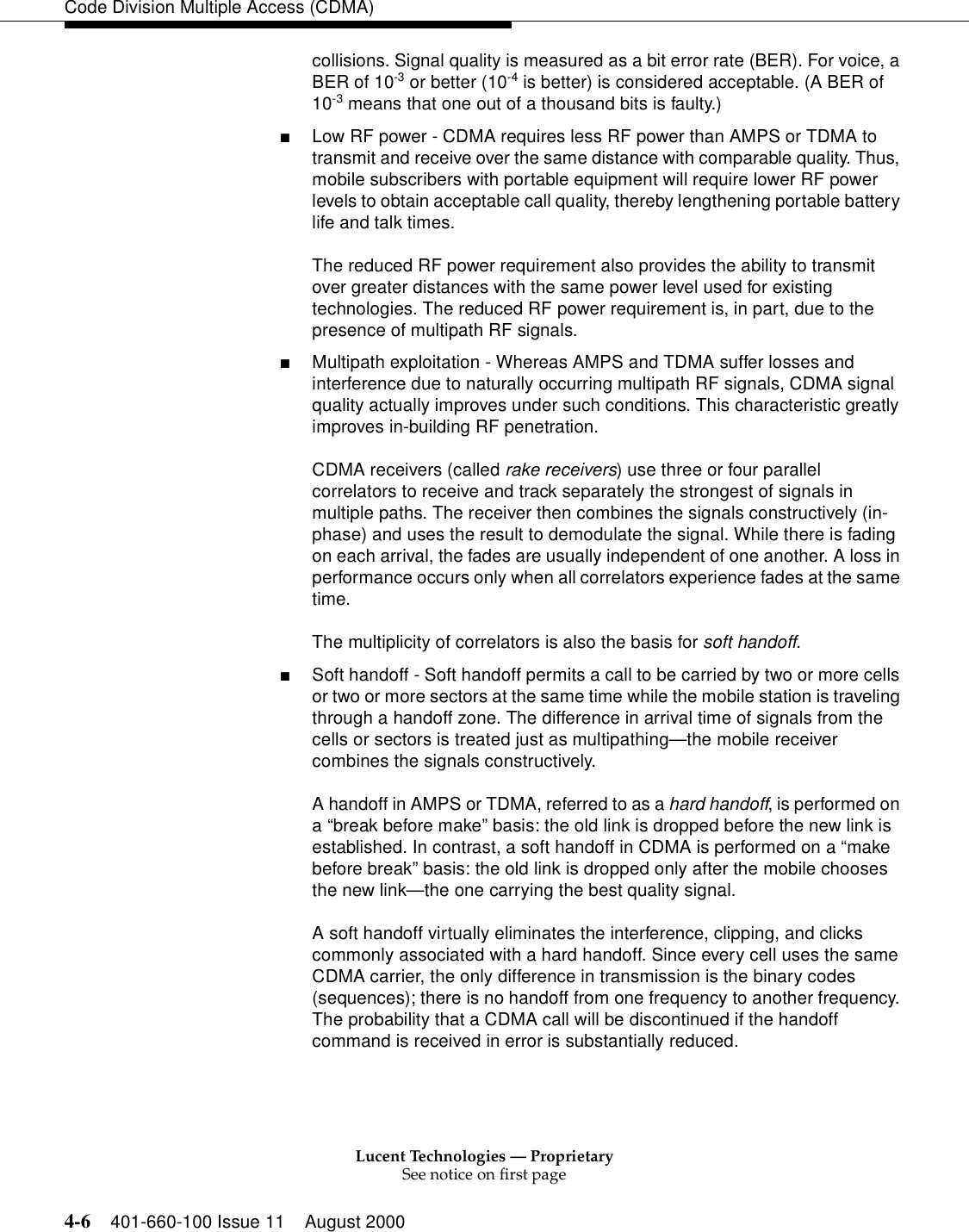
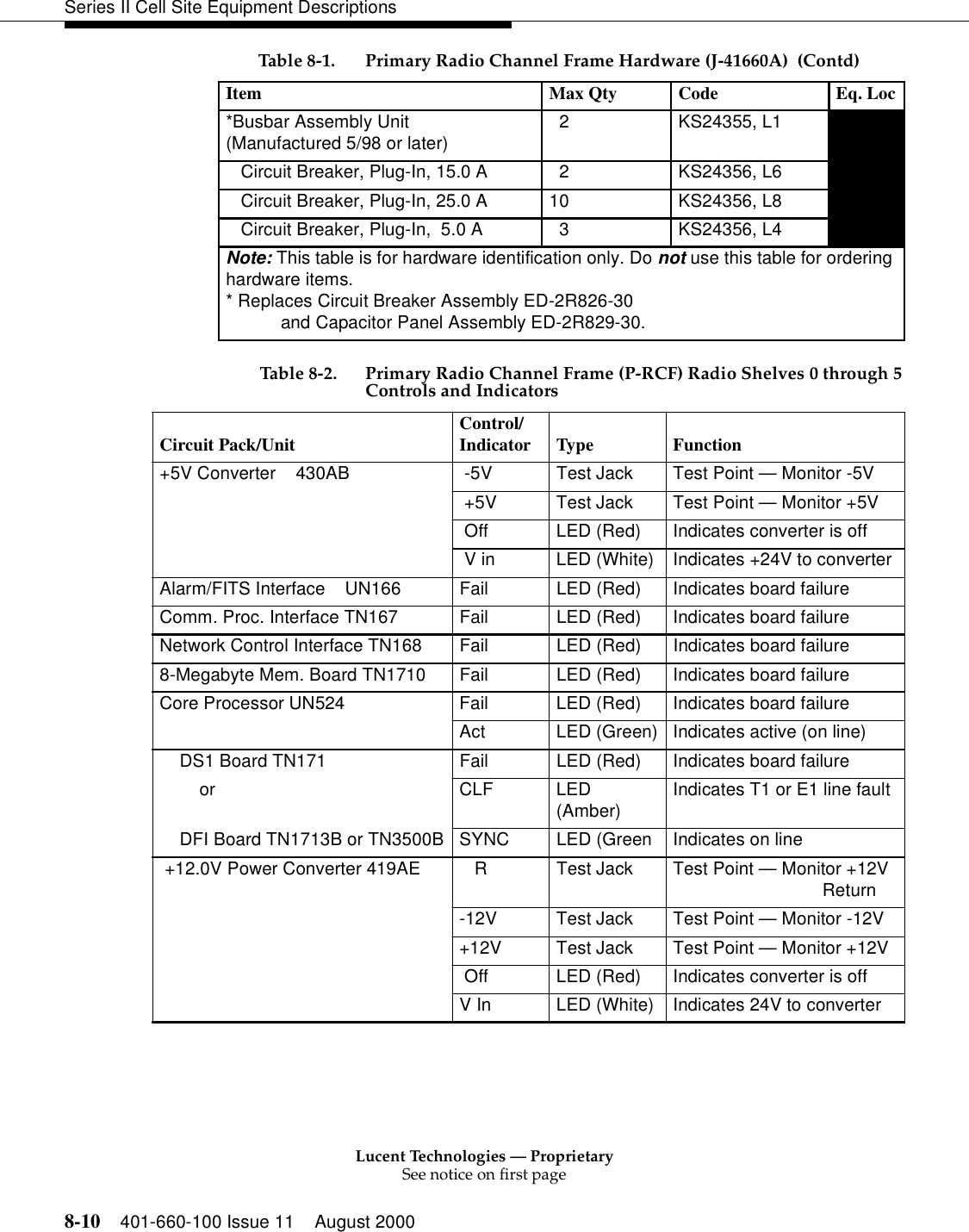
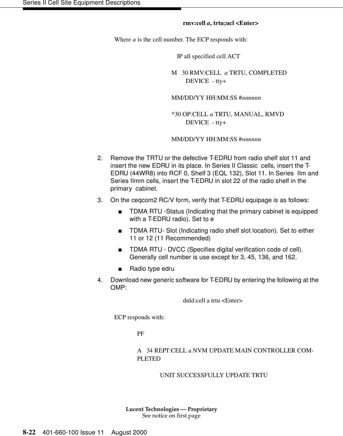
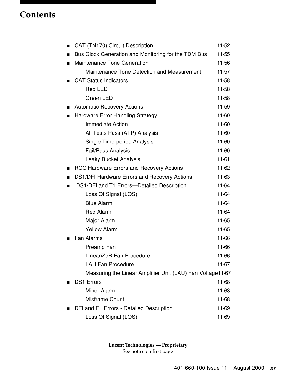
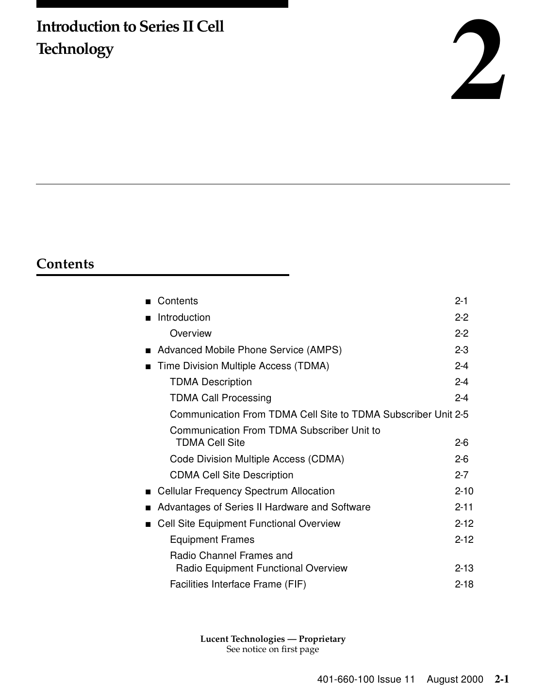
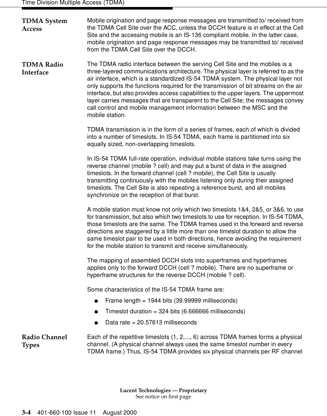
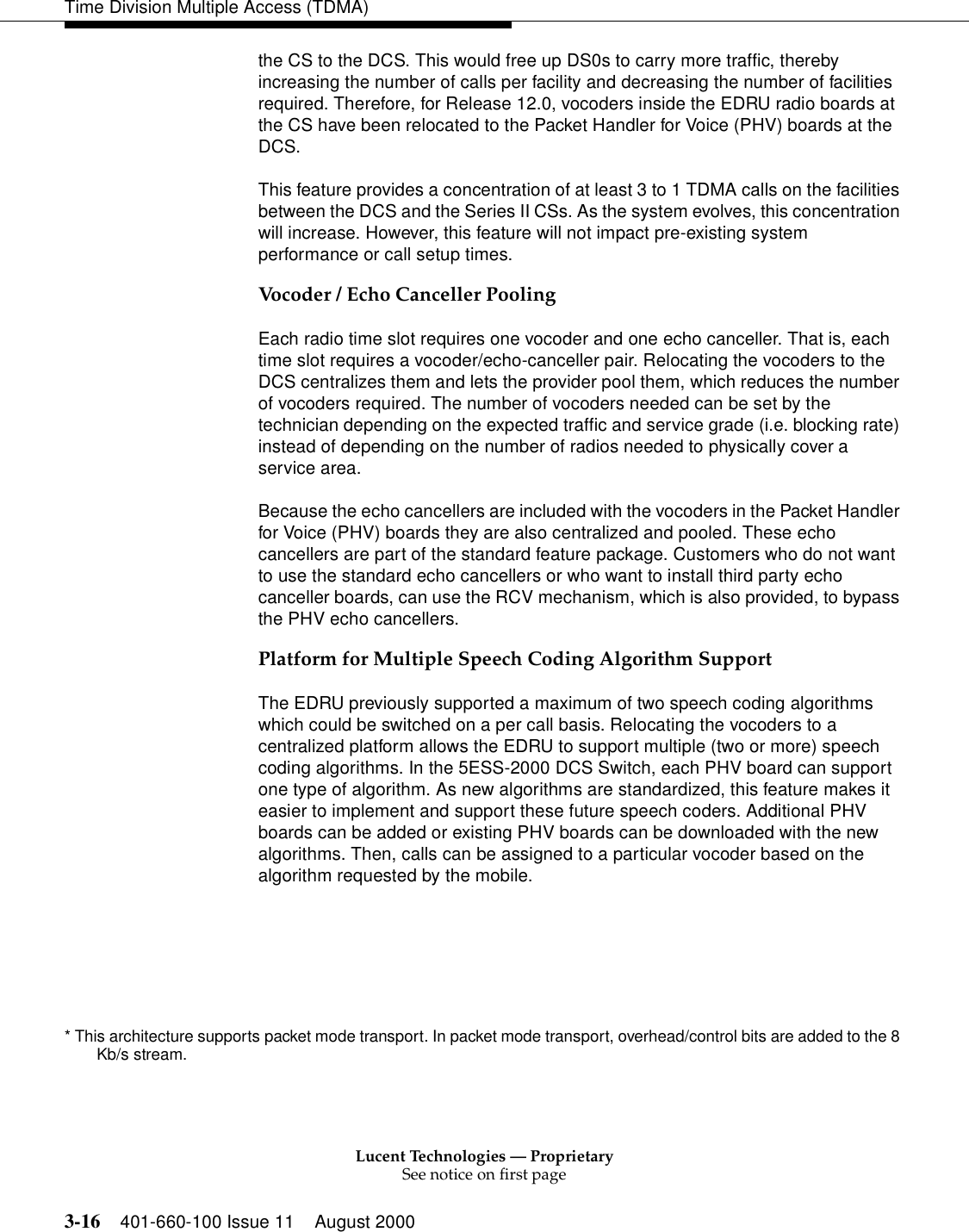
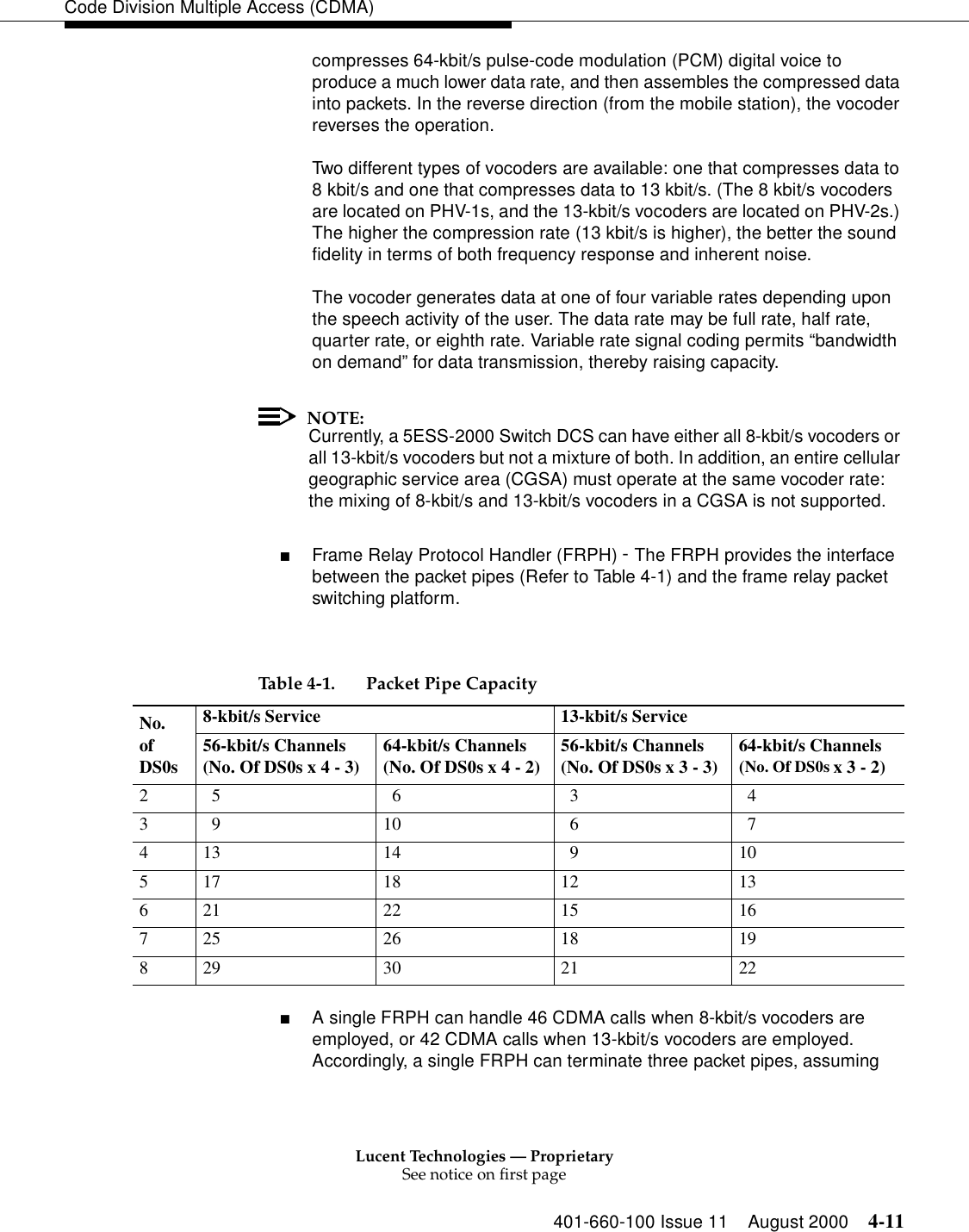
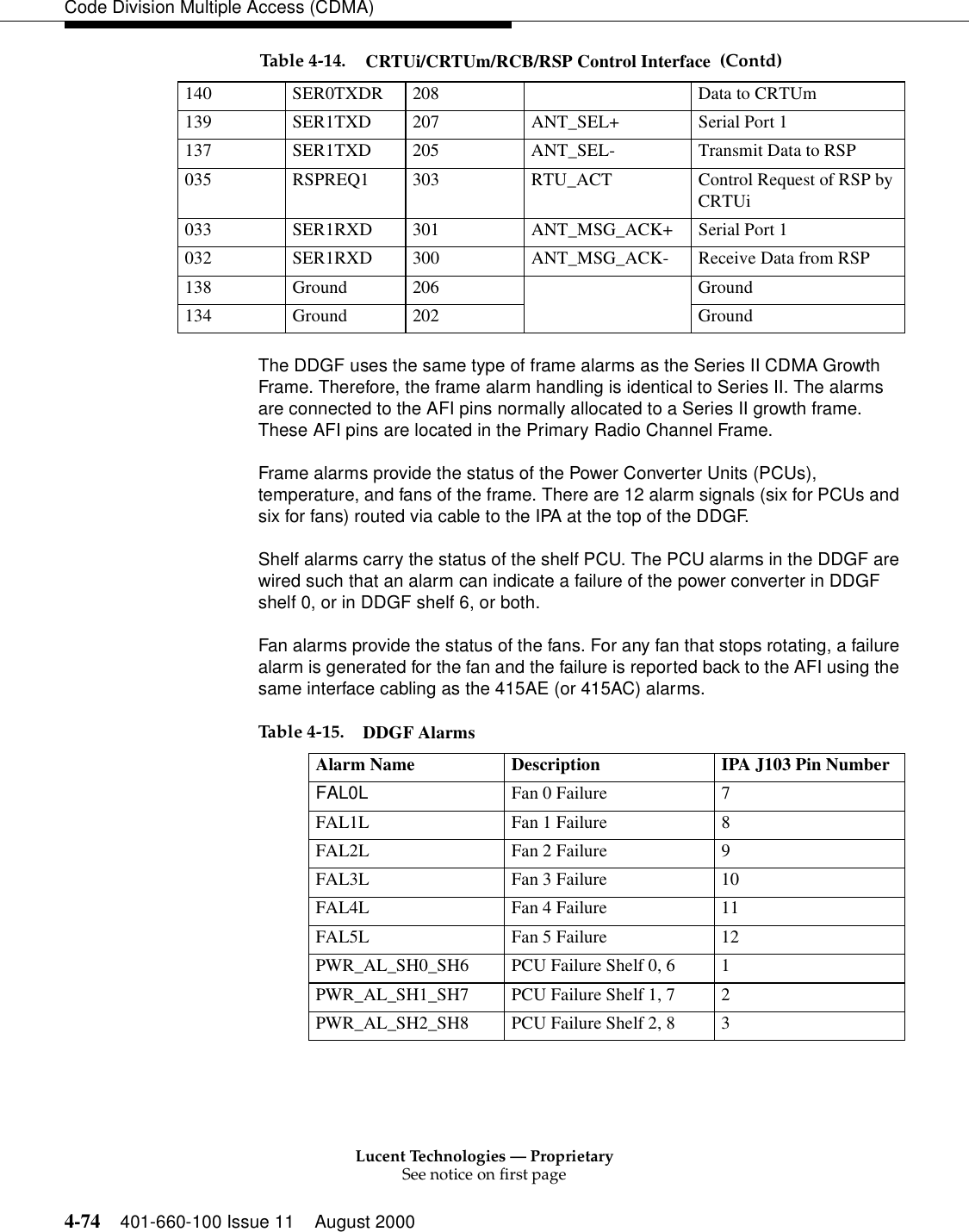
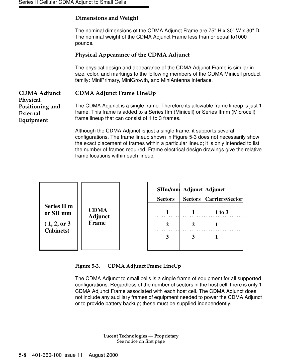
![Lucent Technologies — ProprietarySee notice on first page401-660-100 Issue 11 August 2000 4-7Code Division Multiple Access (CDMA)■High level of security - Should a spread-spectrum signal be intercepted, the data cannot be decoded without the knowledge of the appropriate binary code. ■Spread-spectrum transmission is not totally secure, but it is private. A casual listener will not be able to intercept the message.For microcell and in-building systems - CDMA is a natural waveform suitable for microcell and in-building wireless systems because of its tolerance to noise and interference.Capacity The major system factors determining the capacity of the CDMA system are as follows:■Voice duty cycle (@ 3.5)■Frequency reuse factor (1)■Number of sectors in the cell (1 to 6)■Processing gain■Required Ec/IoThe processing gain of the CDMA system is given by the ratio of the binary code rate (1.2288 Mbit/s) to the baseband data rate (9.6 or 14.4 kbit/s). For a baseband data rate of 9.6 kbit/s, the processing gain is approximately 21 dB.Ec/Io is a signal-quality measurement, where Ec is the energy per bit, and Io is the interference power per hertz. (Ec/Io at the baseband is closely related to the carrier-to-interference [C/I] ratio received at the RF.) The higher Ec/Io, the better the signal quality.](https://usermanual.wiki/Alcatel-Lucent-USA/CMP-40.users-manual-1/User-Guide-161958-Page-102.png)
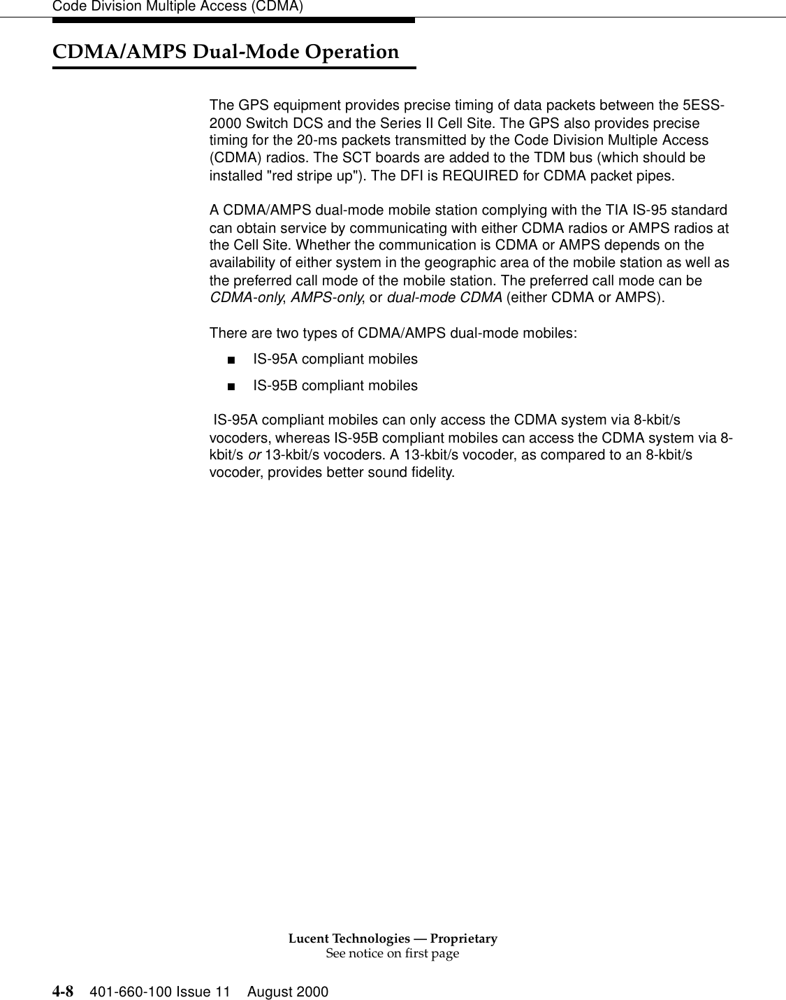
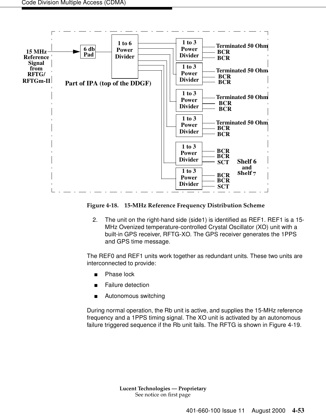
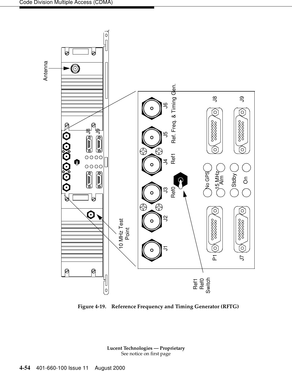
![Lucent Technologies — ProprietarySee notice on first page401-660-100 Issue 11 August 2000 4-57Code Division Multiple Access (CDMA)!CAUTION:The HP8481H Power Sensor Head may be permanently damaged if a 30dB attenuator is not connected between the sensor head and the foam jumper measurement point.Pilot-only calibration is used for the LAC/MLAC amplifiers. The pilot-only calibration generates a constant pilot with the paging, sync, and traffic channels disabled.[1] Update cell translation forms with the following data. Note the original data so that it can be restored after power has been set:■Update ceqface:Pilot Channel Gain (dgu)108Paging Channel Gain (dgu)0Sync Channel Gain (dgu)0■Update ceqcom2:LAC TypelMax Power13.5BCR Attenuation Factor (dB)10NOTE:The BCR Attenuation Factor was in the ceqface form prior to ECP 12.0.NOTE:Repeat this procedure for the CDMA clusters associated with each carrier. There should be one cluster for each carrier.[2] If inhibited, allow call processing:alw:cell a, cp[3] Switch all faceplate switches (BCR and RCU) to OFF.[4] Remove all BBAs from service:rmv:cell a, bba b; ucl!CAUTION:To prevent personal injury and damage to cell equipment, never disconnect RF cables while radio units are transmitting.](https://usermanual.wiki/Alcatel-Lucent-USA/CMP-40.users-manual-1/User-Guide-161958-Page-152.png)
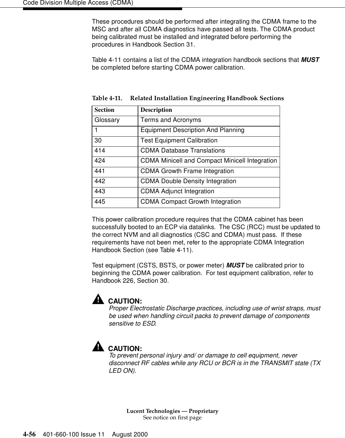
![Lucent Technologies — ProprietarySee notice on first page4-58 401-660-100 Issue 11 August 2000Code Division Multiple Access (CDMA)[5] Disconnect the foam jumper cable from the transmit antenna associated for the CDMA cluster being adjusted. The foam jumper is the cable connecting the transmit filter J4 port to the antenna cable at the cell hatch plate.[6] Use an ITE-6924 test cable to connect the HP8921A or HP8935 RF In port to the foam jumper cable, or connect the HP437B/ HPE4418A power meter sensor through the 30dB attenuator to the foam jumper cable. Do not use a test cable with a power meter unless an offset value is entered in the meter.[7] Operate the faceplate switch on the BCR to be adjusted to AUTO and use the following command to unconditionally restore the BBA for the desired sector and carrier:rst:cell a, bba b; uclb = BBA member being adjusted.[8] Verify the BCR ACT LED comes on.[9] If this is a new CDMA cell site and there is no analog service, then the pre-amp may have never been adjusted. If the pre-amp has never been adjusted for this cell site, then adjust the LAC/MLAC pre-amp to electrical center before adjusting the first BCR. To do this, turn the LAC pre-amp from its minimum power level to its maximum power level and then set it at the electrical mid-point.NOTE:Anytime a LAC pre-amp is adjusted, all the RCUs and BCRs transmitting on that LAC must be re-adjusted.[10] The metering device should display the approximate desired power. If the reading is beyond the maximum and minimum values shown in Table 4-12, ensure that the ceqface and ceqcom2 forms are correct and verify the BCR transmit path before attempting to adjust the BCR.[11] Adjust the BCR faceplate pot to achieve the desired level as specified in Table 4-12.Table 4-12.MeteringDevice ApproximateMinimum DesiredPower ApproximateMaximumCSTSBSTS 29 dBm0.8 W 33 dBm2 W 41 dBm13 WHP437BHPE4418A(30dB Attn)-1 dBm0.8 mW 3 dBm2 mW 11 dBm13 mW](https://usermanual.wiki/Alcatel-Lucent-USA/CMP-40.users-manual-1/User-Guide-161958-Page-153.png)
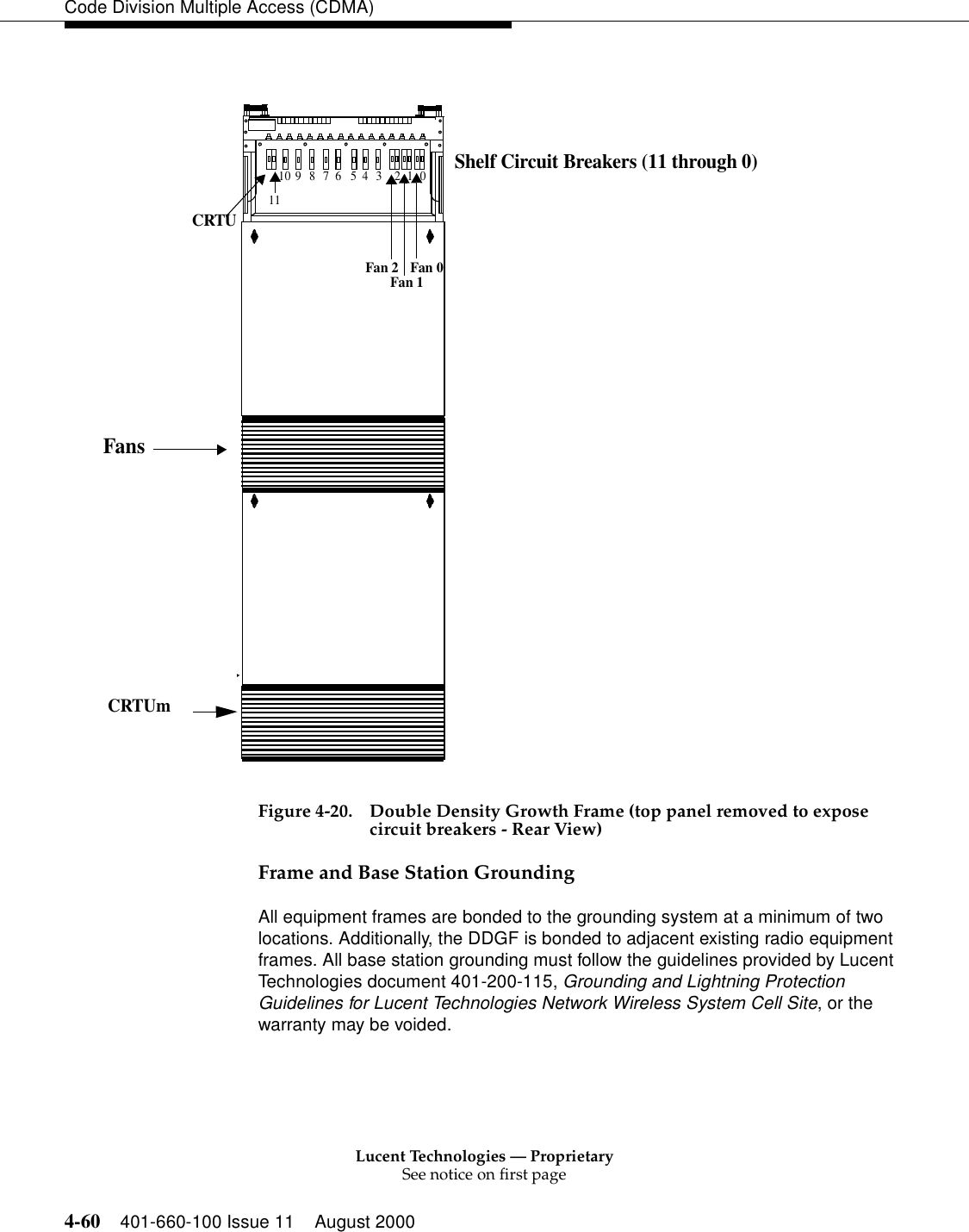
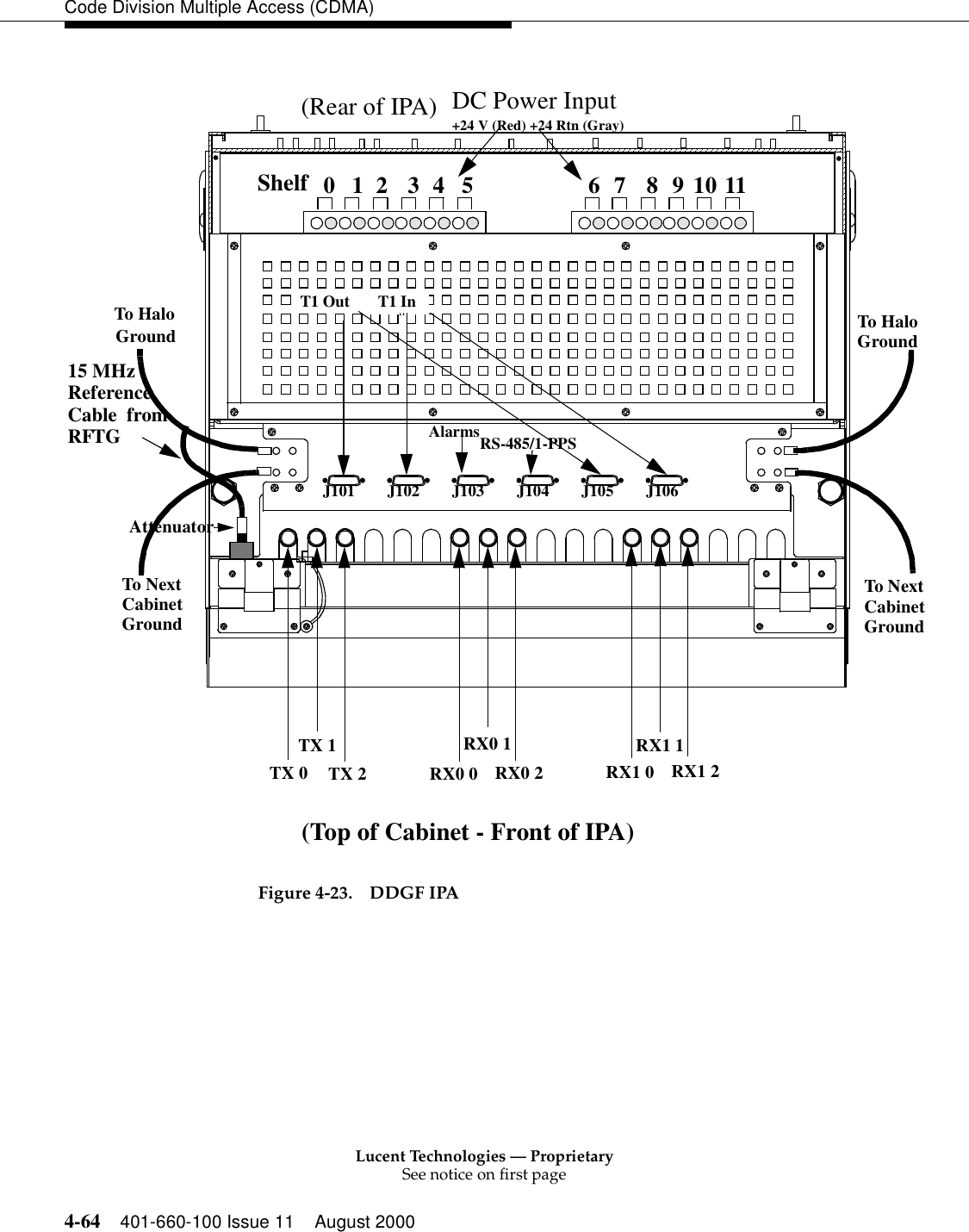
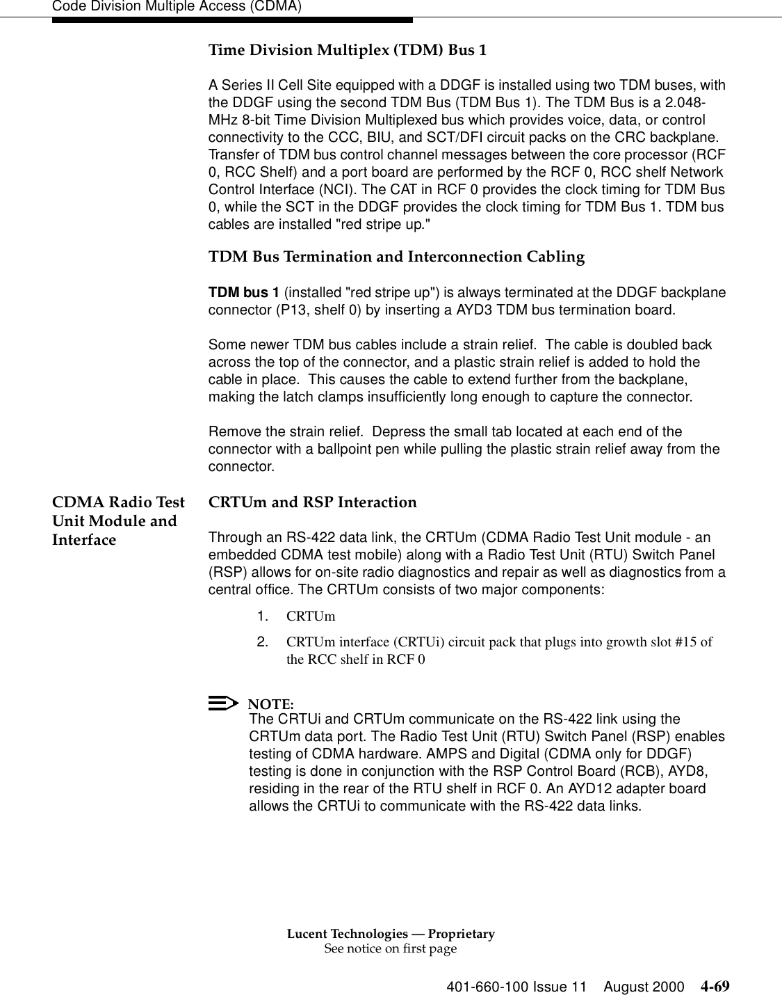
![Lucent Technologies — ProprietarySee notice on first page401-660-100 Issue 11 August 2000 4-59Code Division Multiple Access (CDMA)BCR Attn = 10, Pilot DGU = 108, Page/Sync DGU = 0/0Amplifier type = l, Max_power = 13.5[12] When the desired level is set, operate the BCR faceplate switch to OFF.[13] To set power on a multiple carrier system, repeat steps [7] through [12] for each remaining carrier cluster on the sector the metering device is connected to. If a LAC/MLAC pre-amp was adjusted to electrical center, do not re-adjust it.[14] When BCR power for all carriers of this sector have been set, disconnect the metering device from the foam jumper and connect the foam jumper back to the antenna cable.[15] Repeat steps [5] through [14] for each BCR associated with the remaining sectors.[16] When power is set for all BCRs, restore the original Pilot, Page, Sync, Max Power, and BCR Attenuation values to the ceqface and ceqcom2 forms.[17] Ensure that all the CDMA clusters have been adjusted and that the transmit antennas have all been reconnected.[18] Switch all faceplate switches (BCR and RCU) to AUTO.[19] Perform a cell stable clear:init:cell a: scGrounding Requirements The DDGF requires two separate kinds of grounding, as follows:1. 24 Volt DC Return (Grounding) 2. Frame Grounding (FRM_GRD)Volt DC Return (Grounding)The +24 V DC return feeders are connected to the return bus at the Battery/Rectifier power plant. The return bus in the Battery/Rectifier power plant is bonded to the grounding system with the appropriate grounding conductor.](https://usermanual.wiki/Alcatel-Lucent-USA/CMP-40.users-manual-1/User-Guide-161958-Page-154.png)
![Lucent Technologies — ProprietarySee notice on first page401-660-100 Issue 11 August 2000 4-75Code Division Multiple Access (CDMA)415AE (or 415AC) DC-To-DC Converter AlarmsThe alarms on each CRC shelf are 415AE (or the older 415AC) power unit alarm and circuit pack alarms. Alarms and/or faults associated with the circuit packs are handled at the pack level.The Power Unit Alarm (relay contact) and LED Indicators are as follows:■Low output voltage alarm if the output voltage falls below 80% of nominal (RED LED turns ON, relay contacts close)■High output voltage alarm if the output voltage is greater than 120% of nominal (output turns OFF, unit latches OFF, RED LED turns ON, relay contacts close). The input voltage must be disconnected before the latch will clear■Red LED on faceplate indicates an alarm■Green LED on faceplate indicates the presence of input voltage■Single isolated contact closure upon LV alarm or HV shutdown■Relay contacts connected to the backplane [ALM1 (Pin 113) and ALM2 (Pin 014)]. The ALM2 pin is connected to ground. A relay closure connects ALM1 to ALM2 which indicates an alarm (Logic 0)+5 V DC performance is not guaranteed below +20 V DC input to 415AE (or the older 415AC).CDMA CRC Shelf Circuit Pack LED IndicatorsThe CDMA CRC shelf Circuit packs have various Light Emitting Diode (LED) indicators on their faceplates. These LEDs indicate either operational or alarm conditions. PWR_AL_SH3_SH9 PCU Failure Shelf 3, 9 4PWR_AL_SH4_SH10 PCU Failure Shelf 4, 10 5PWR_AL_SH5_SH11 PCU Failure Shelf 5, 11 6Table 4-15. DDGF Alarms (Contd)](https://usermanual.wiki/Alcatel-Lucent-USA/CMP-40.users-manual-1/User-Guide-161958-Page-170.png)

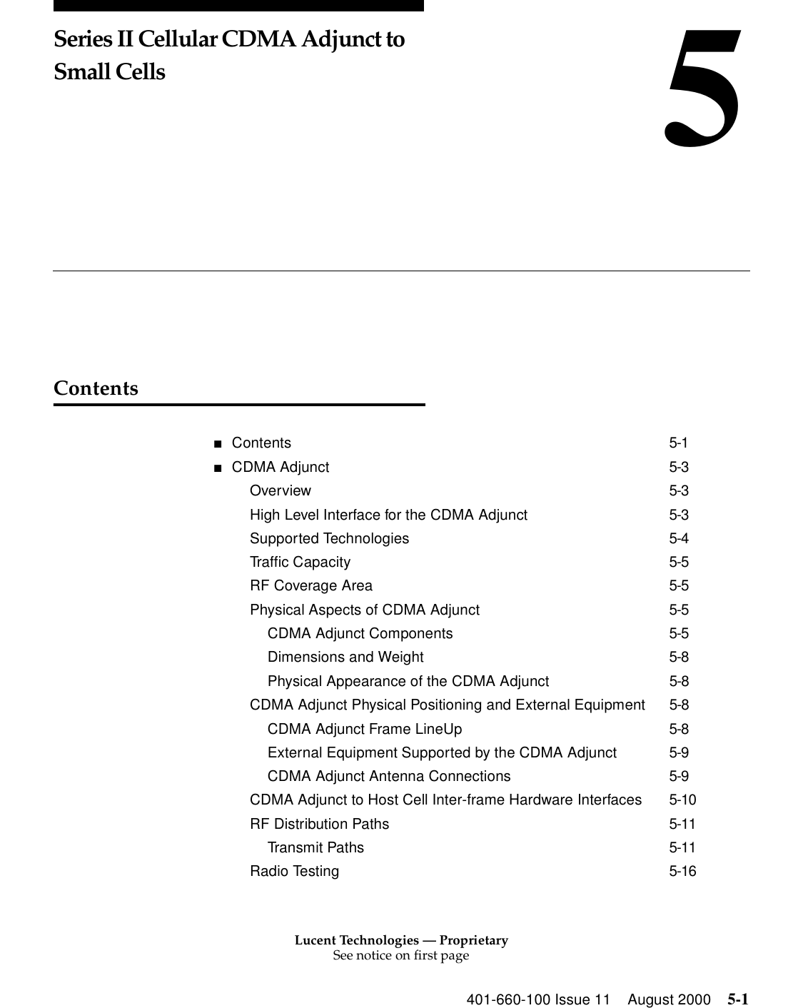
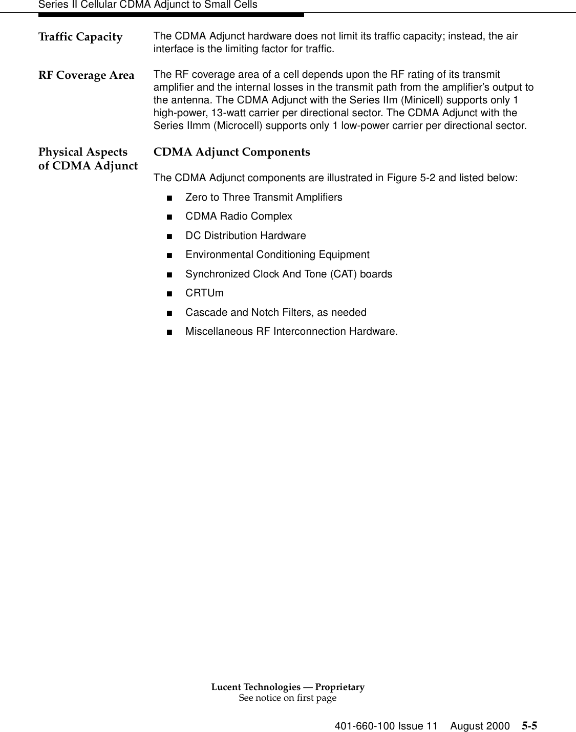
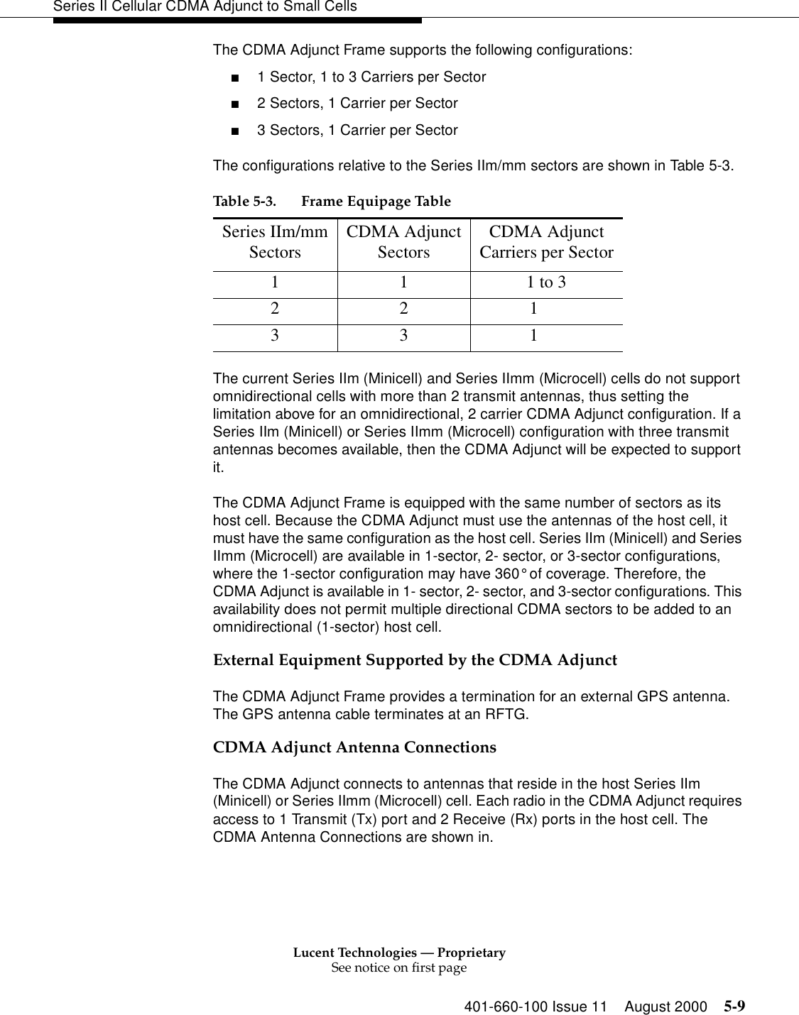
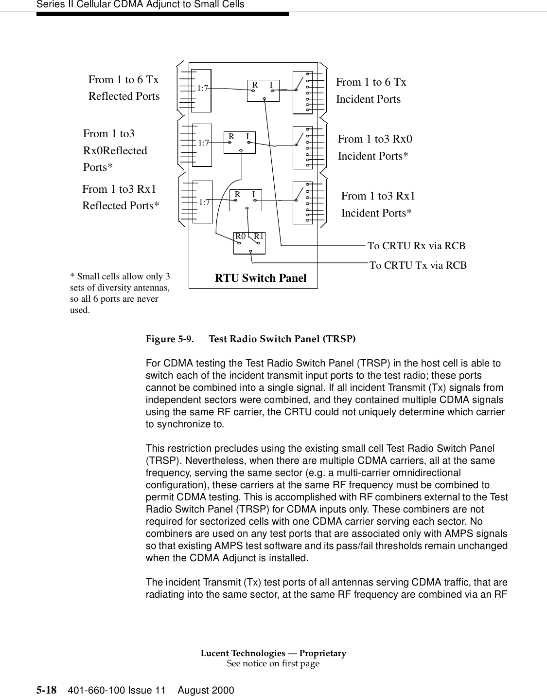
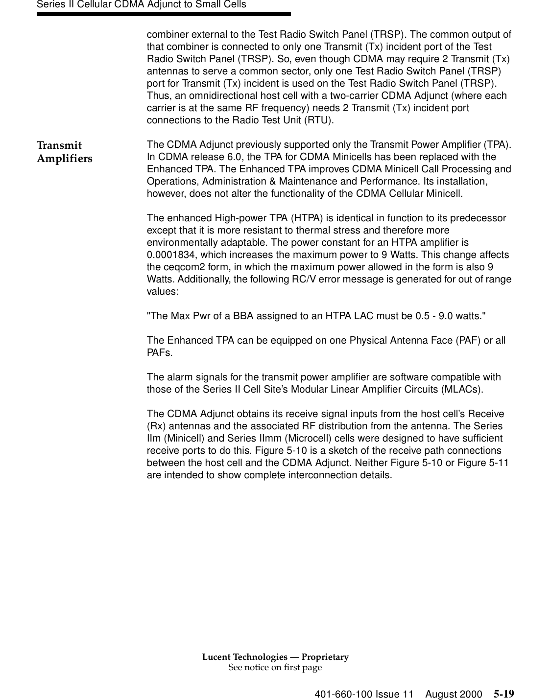
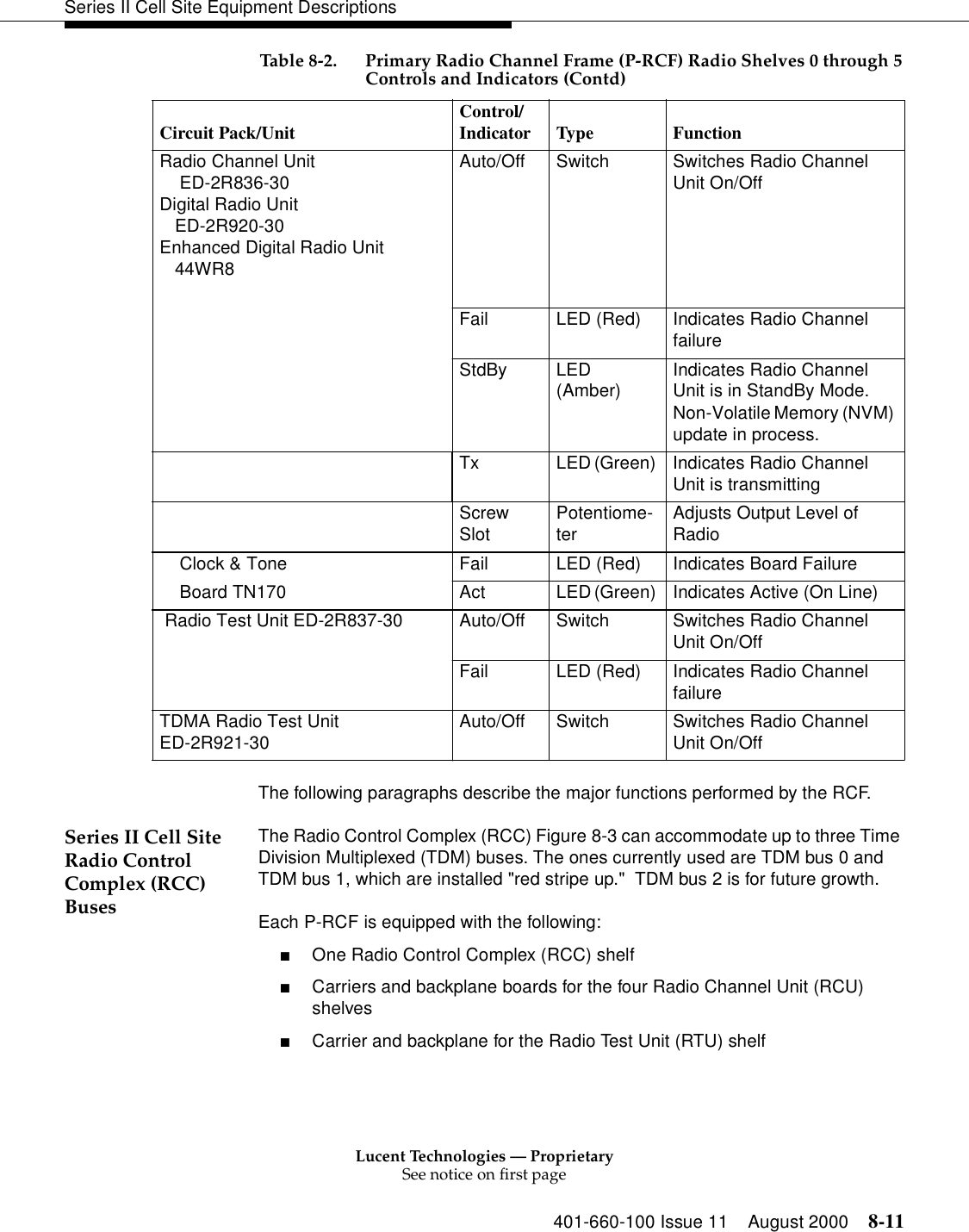
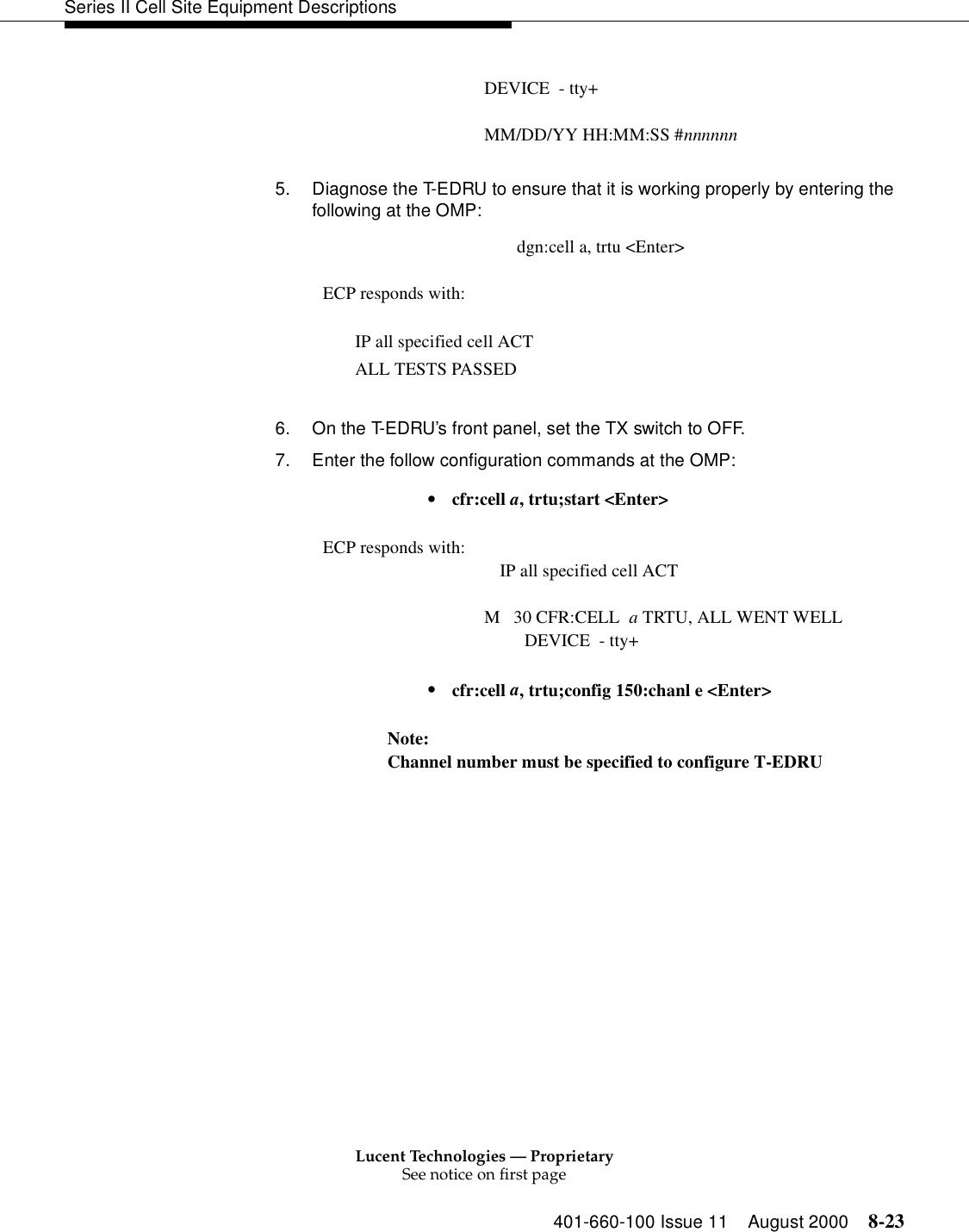
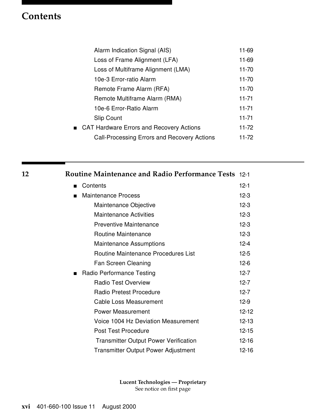
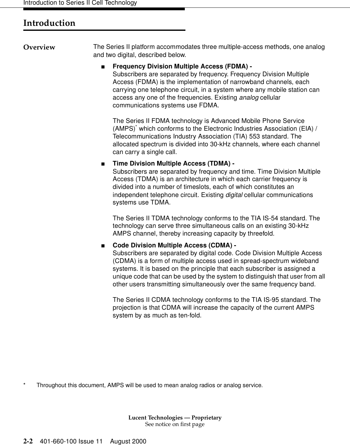
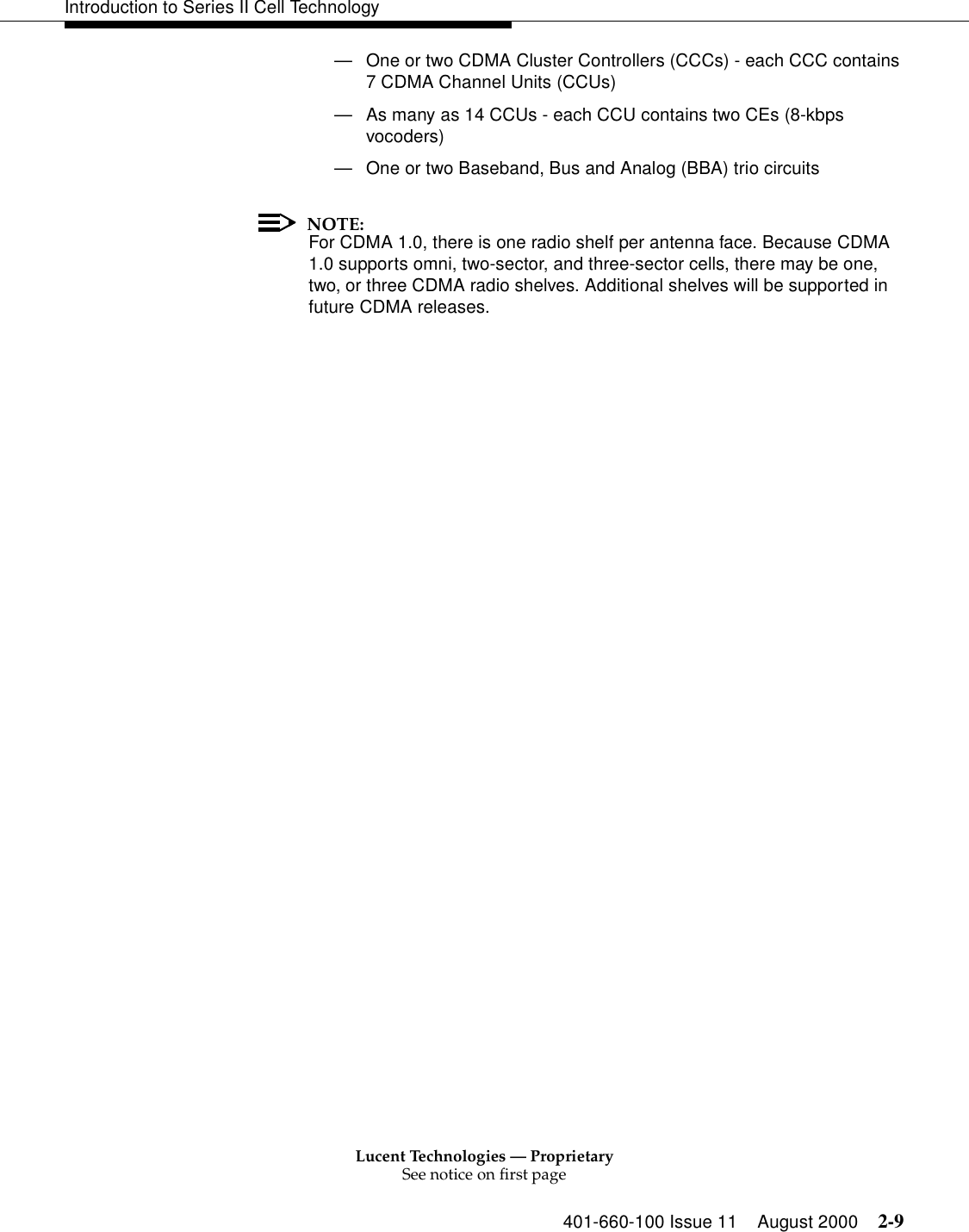
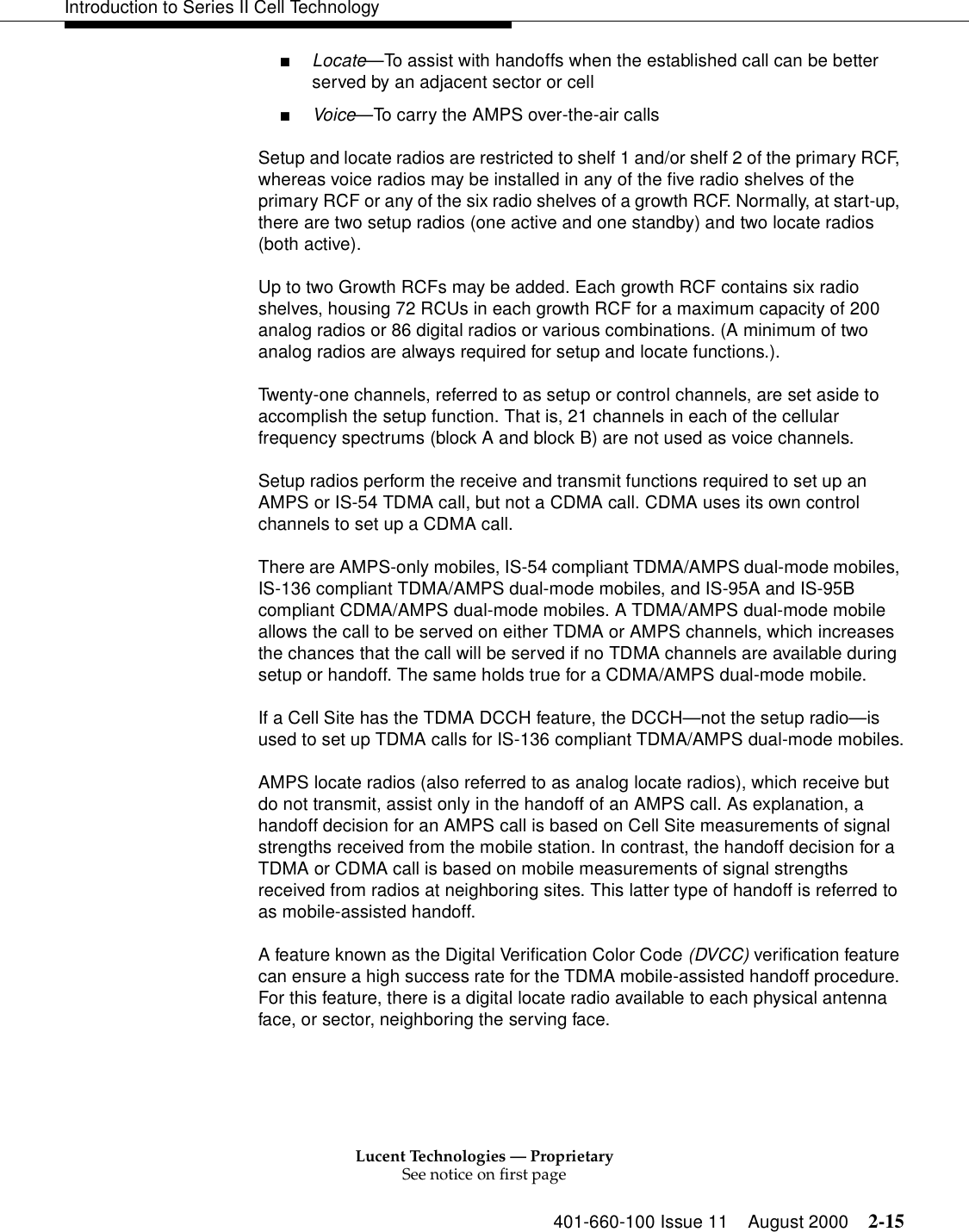
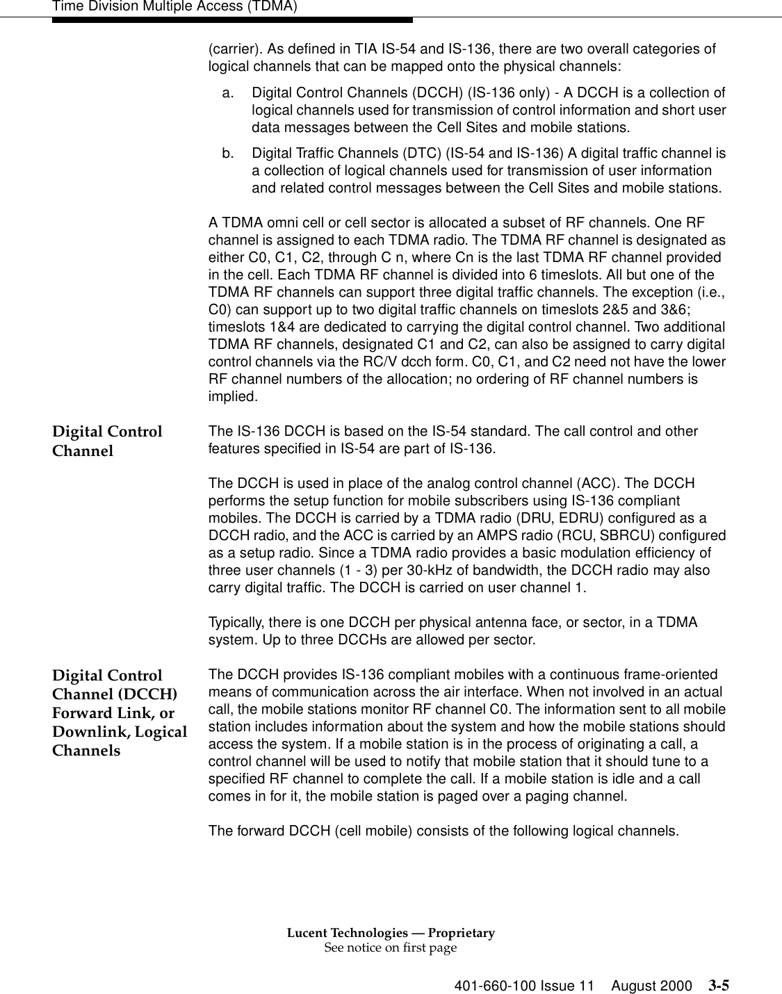
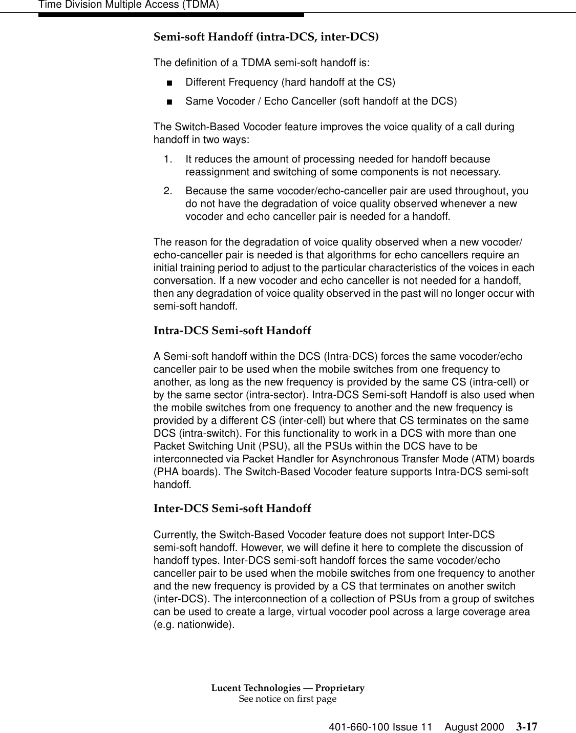
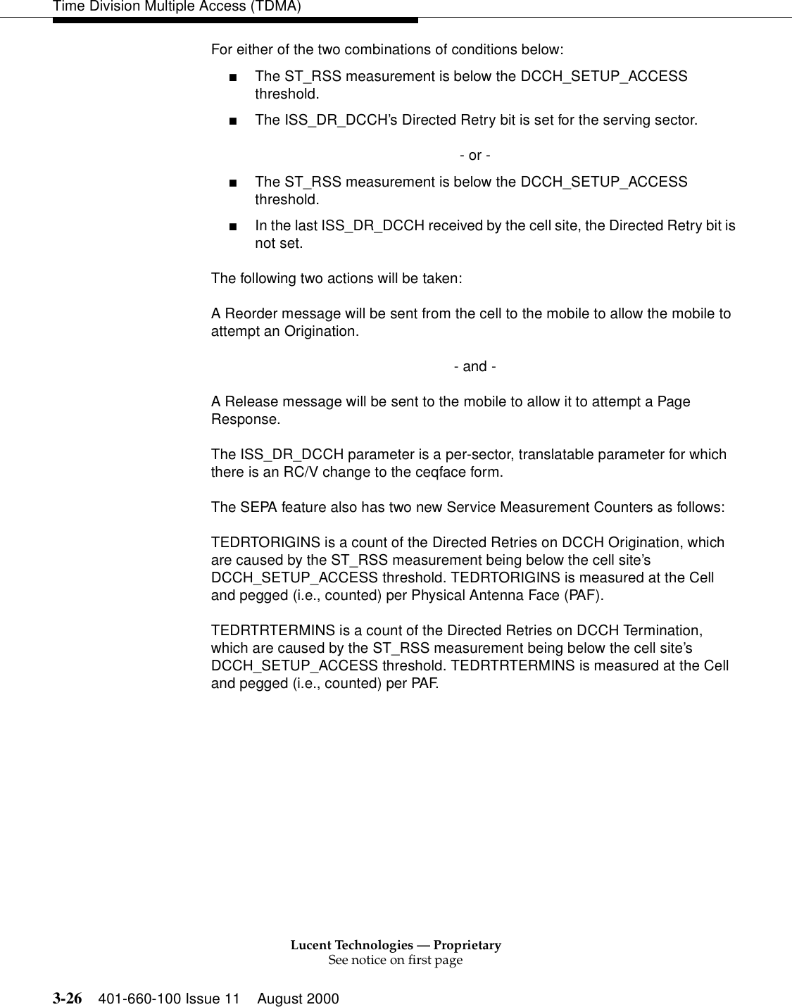
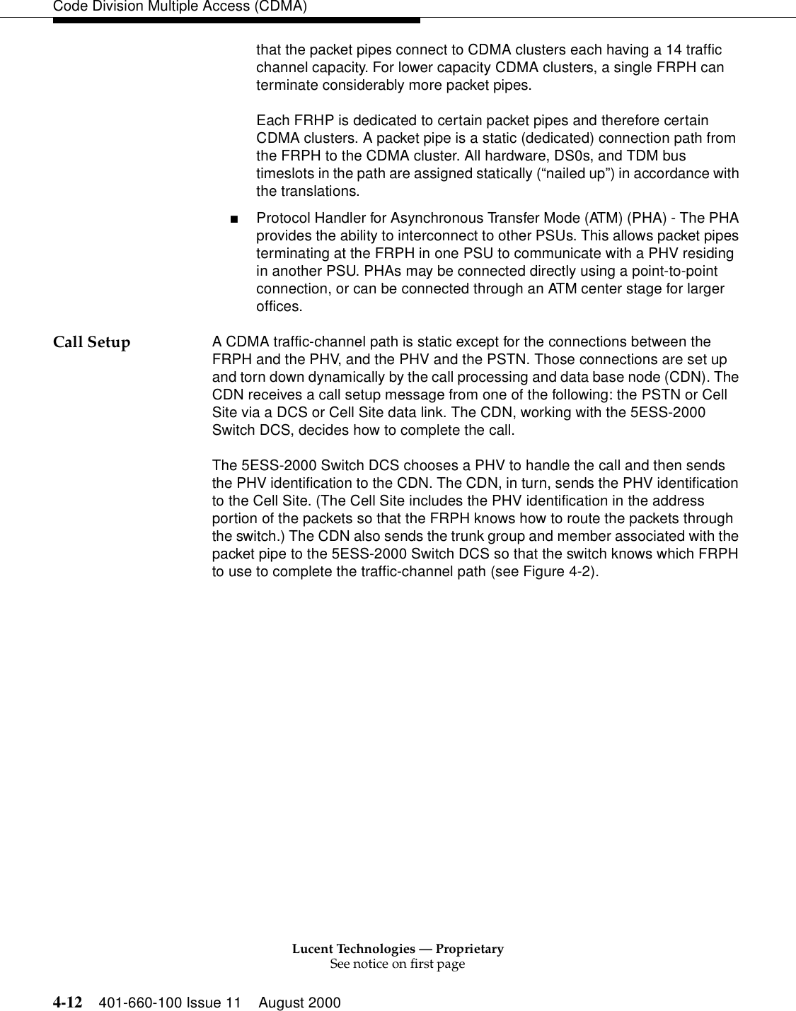
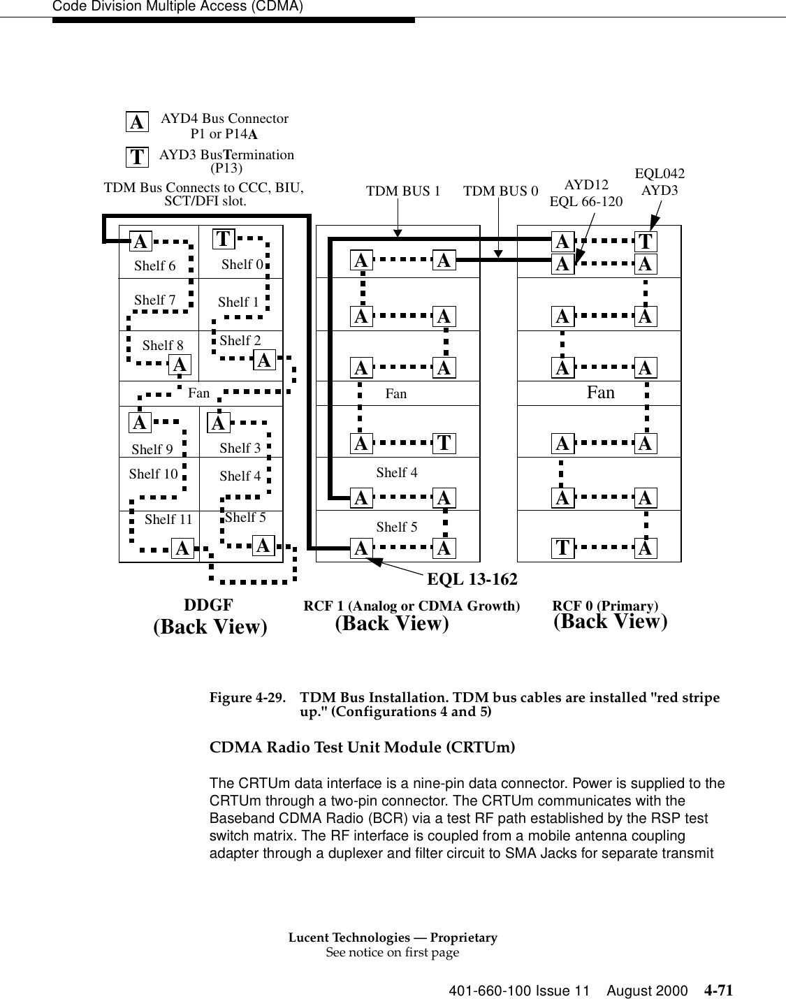
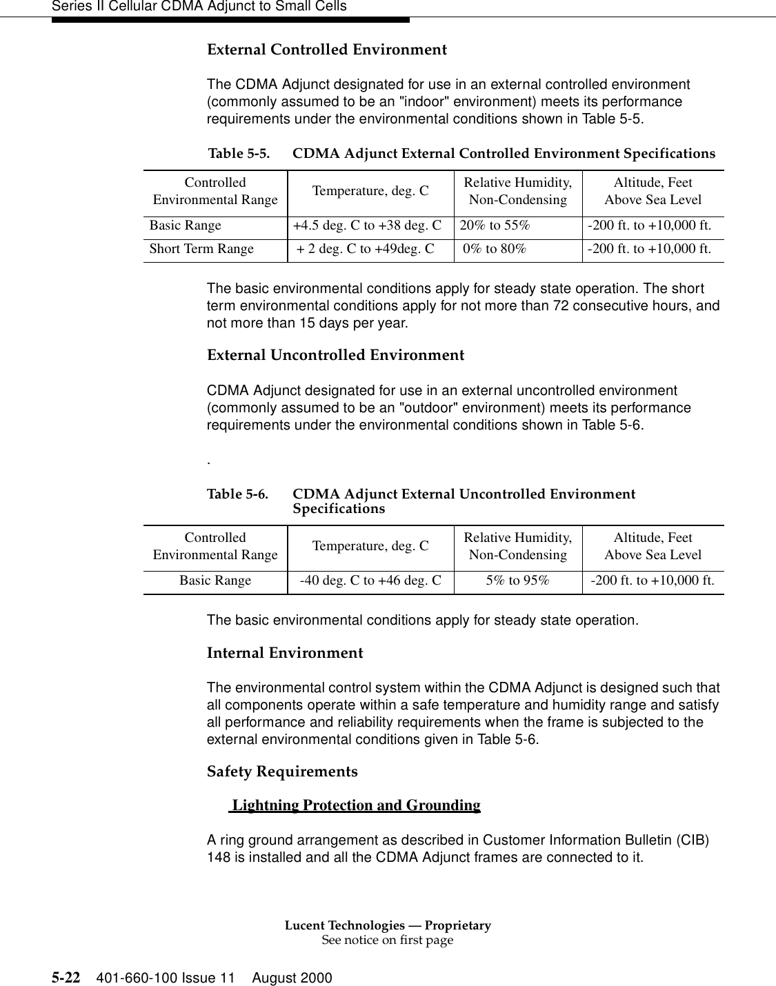
![Lucent Technologies — ProprietarySee notice on first page401-660-100 Issue 11 August 2000 5-21Series II Cellular CDMA Adjunct to Small Cells Figure 5-11. CDMA Transmit Path (Smm Only)Environmental, Safety, and Handling RequirementsEnvironmental requirements: The conditions under which the equipment must operate. Safety requirements: How the equipment affects the well-being of personnel who operate the equipment or who are in its vicinity Handling requirements: How the equipment survives the rigors of shipping and storage. The specifications that follow call for the CDMA Adjunct to meet the same environmental, safety, and handling requirements as the host cell to which it is connected.Environmental RequirementsThe 3 basic environments in which the equipment can operate are listed below. Because the environment is defined from the viewpoint of the equipment, an external environment, as seen by the equipment, does not necessarily imply that the equipment is outdoors.External controlled environment: An environment in which the equipment is located inside a building that has its own heating and air conditioning systems to control the temperature and humidity to which the equipment is subjected. External uncontrolled environment: An environment in which the equipment is located outdoors with no heating or cooling equipment provided externally. Internal environment: The environment inside the equipment; does not necessarily imply that equipment is indoors.BasebandCombinerRadioCDMA Adjunct [no antennas]RCUTx0 Rx1Rx0SIImmNote: Only 1 sector is shown, other sectorsare similar.Small CellTx Amp.N:1M:1Dir. Cplr.for CDPD CDMA Tx](https://usermanual.wiki/Alcatel-Lucent-USA/CMP-40.users-manual-1/User-Guide-161958-Page-192.png)


![Lucent Technologies — ProprietarySee notice on first page401-660-100 Issue 11 August 2000 7-11Mini, Micro, and Fiber-Link Series II Cell Site Options—inh:cell a,cp (where a = cell number)—inh:cell a,rtdiag—inh:cell a,ft su—inh:cell a,ft lc■Wait for all in-process calls to complete [all voice RCU, SBRCU, DRU and EDRU Tx (Transmit) LEDs OFF].■Remove all beacon radios (if equipped) from service by entering the following code:—rmv:cell a,ra b;ucl (where a = cell number and b = radio number of beacon)■Remove cell data links to/from MSC by entering the following code:—rmv:cell a,dl 1 2. If a +5-volt PCU 415AC is to be replaced by a +5-volt PCU 430AB, set RCU circuit breaker CB1 to the OFF position and then replace the +5-volt PCU board. Set RCU circuit breaker CB1 to the ON position. If RCU circuit breaker CB1 needs to be replaced, perform the following; otherwise restore the cell back to service.3. To replace RCU circuit breaker CB1, perform the following:■On DC cabinets, remove the 24-volt supply.■On AC cabinets, set the main AC circuit breaker to OFF. The cell will run for about 10 minutes using the backup battery power. Remove the side access panels from the AC pedestal to gain access to the battery positive leads and disconnect the battery.■Remove the four machine screws from the front four corners of the circuit breaker panel and remove the top cover. It may be necessary to clip (remove) cable ties that secure the power wires in order to provide additional installation space.■Remove the machine screws from the DC circuit breaker panel.■Remove 20A RCU circuit breaker CB2 from the circuit panel. Remove two 5/16 nuts from the circuit breaker power terminals and disconnect the power wires.■Install the new 30A circuit breaker by reversing the sequence in which the circuit breaker was removed. ■Ensure that the circuit breaker is oriented correctly and that line and load power wiring is correctly replaced on the circuit breaker. ■Ensure that the circuit breaker power terminal nuts are adequately torqued.](https://usermanual.wiki/Alcatel-Lucent-USA/CMP-40.users-manual-1/User-Guide-161958-Page-234.png)