Alcatel Lucent USA CMP-40 Cellular Base Station Transceiver User Manual users manual 2
Alcatel-Lucent USA Inc. Cellular Base Station Transceiver users manual 2
UserManual.wiki
>
Alcatel Lucent USA
>
CMP-40 User Manual
>
users manual 2
Contents
1.
users manual 1
2.
users manual 2
3.
users manual 3
users manual 2
Navigation menu
Upload a User Manual
Namespaces
Wiki Guide
HTML
PDF
Info
Views
User Manual
Discussion / Help
Navigation
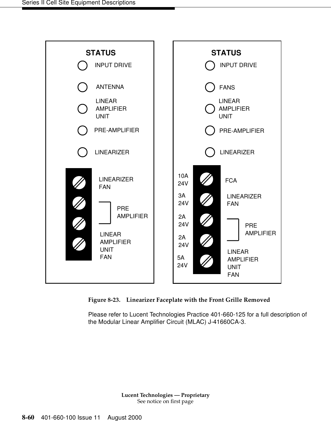
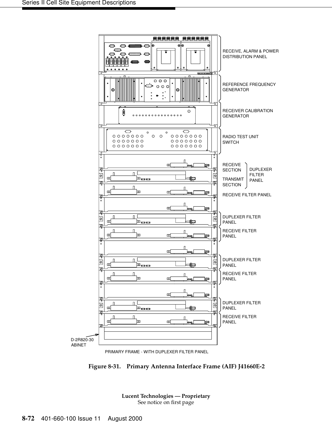
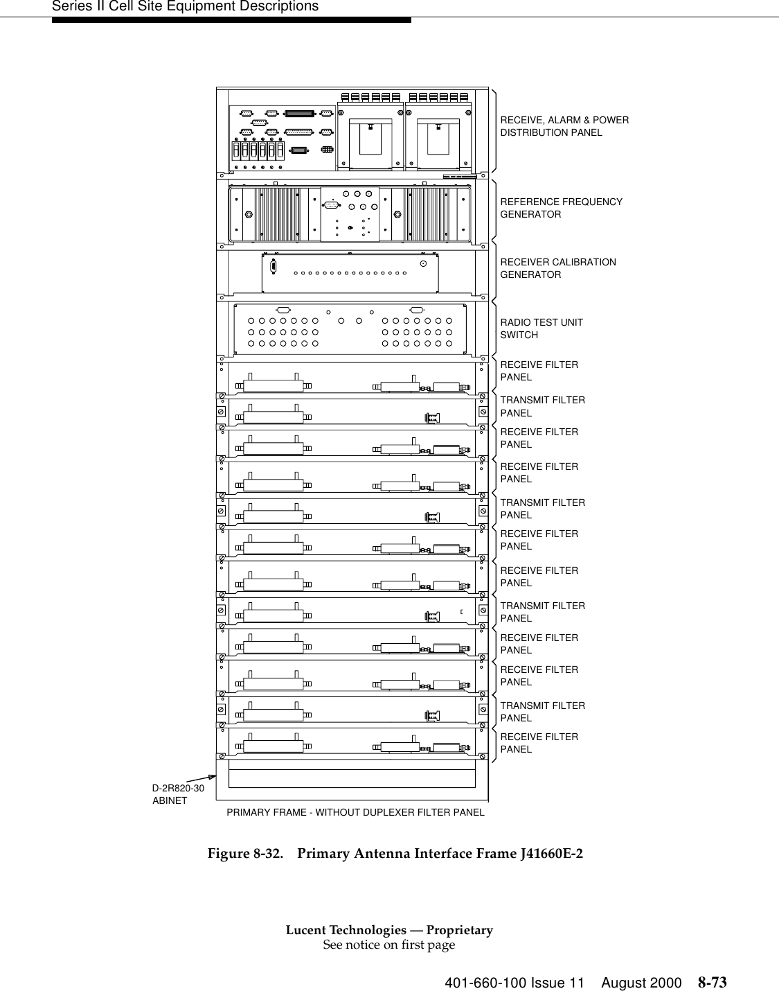
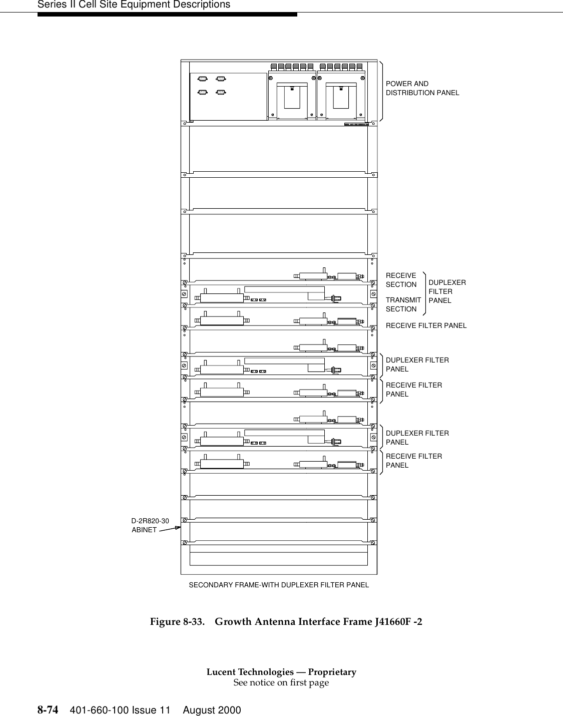
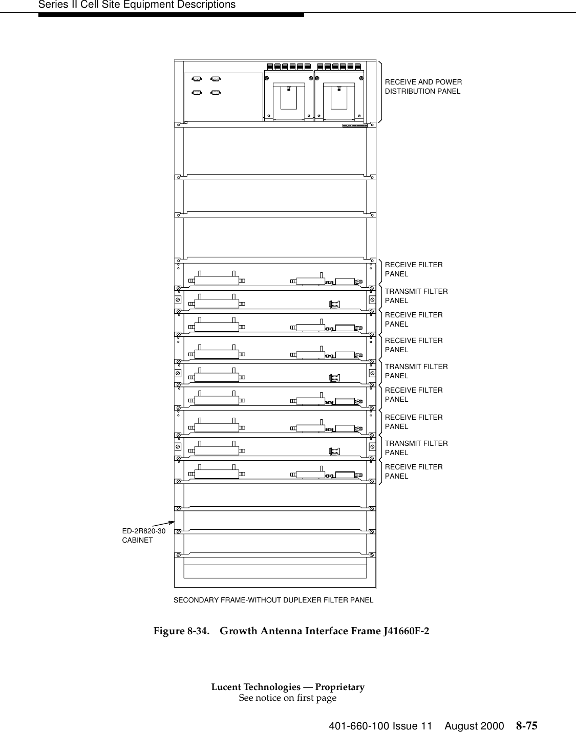

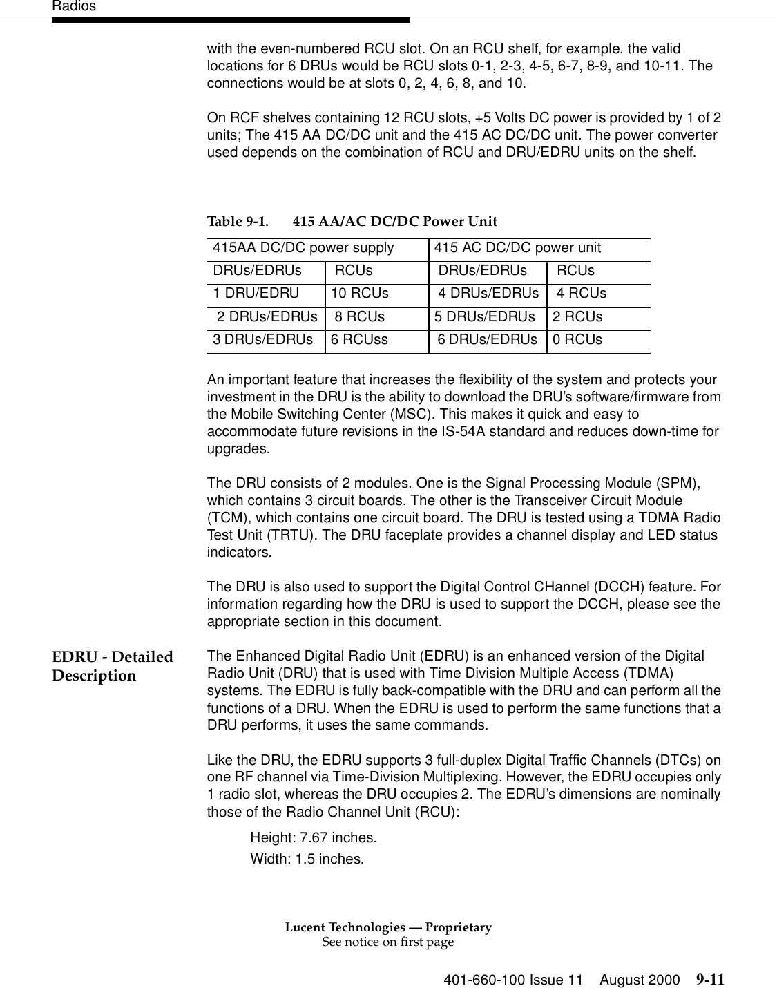
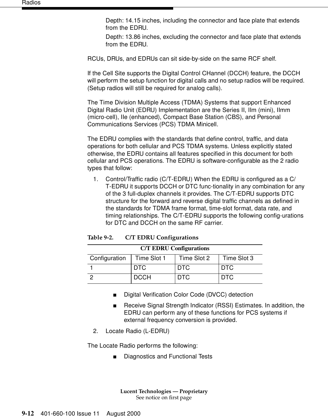
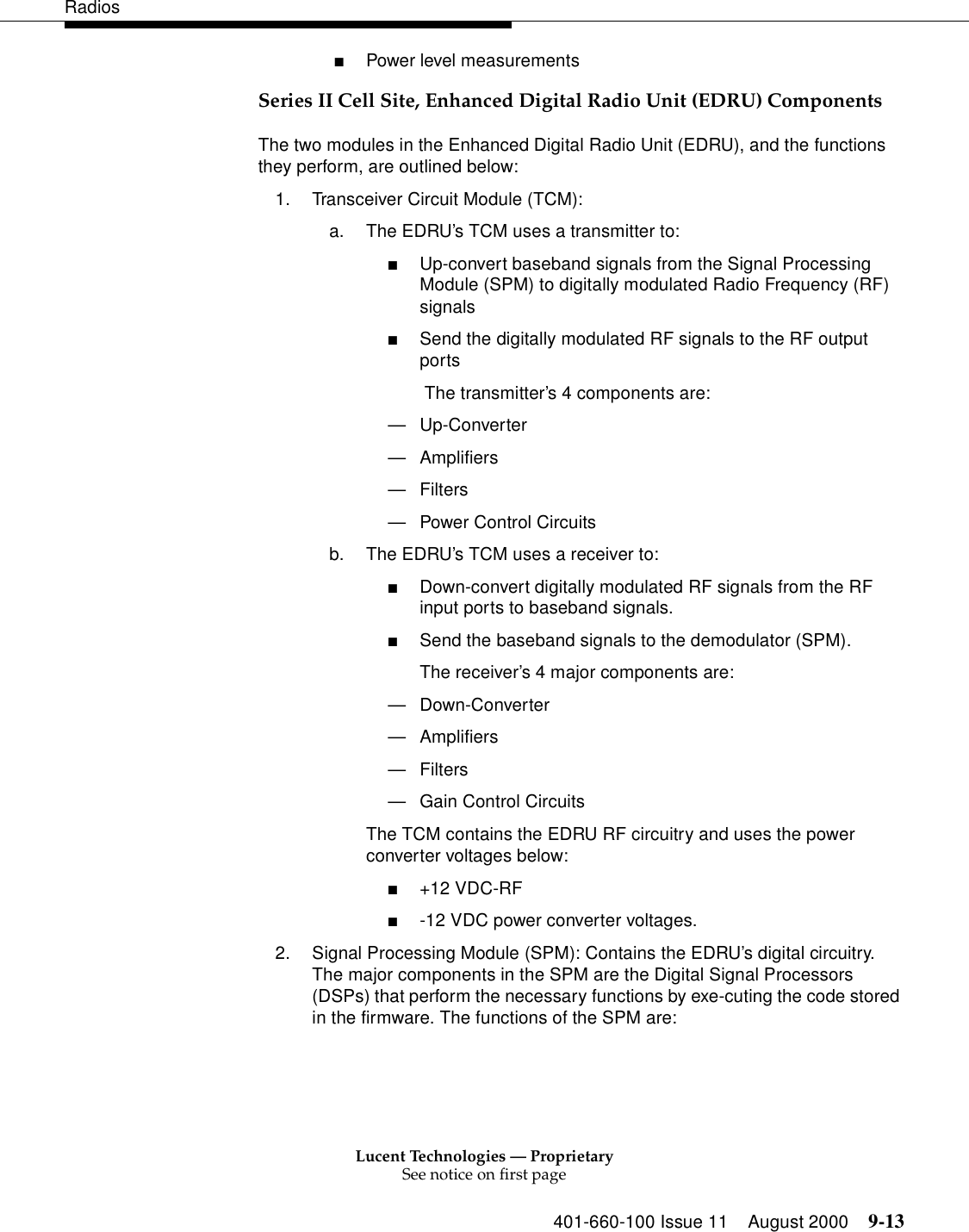
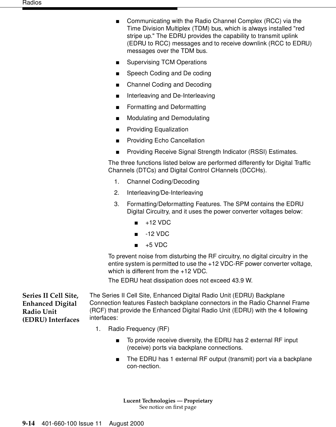
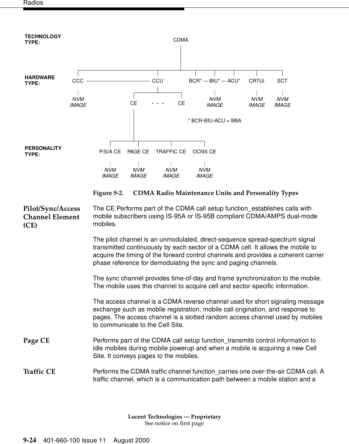


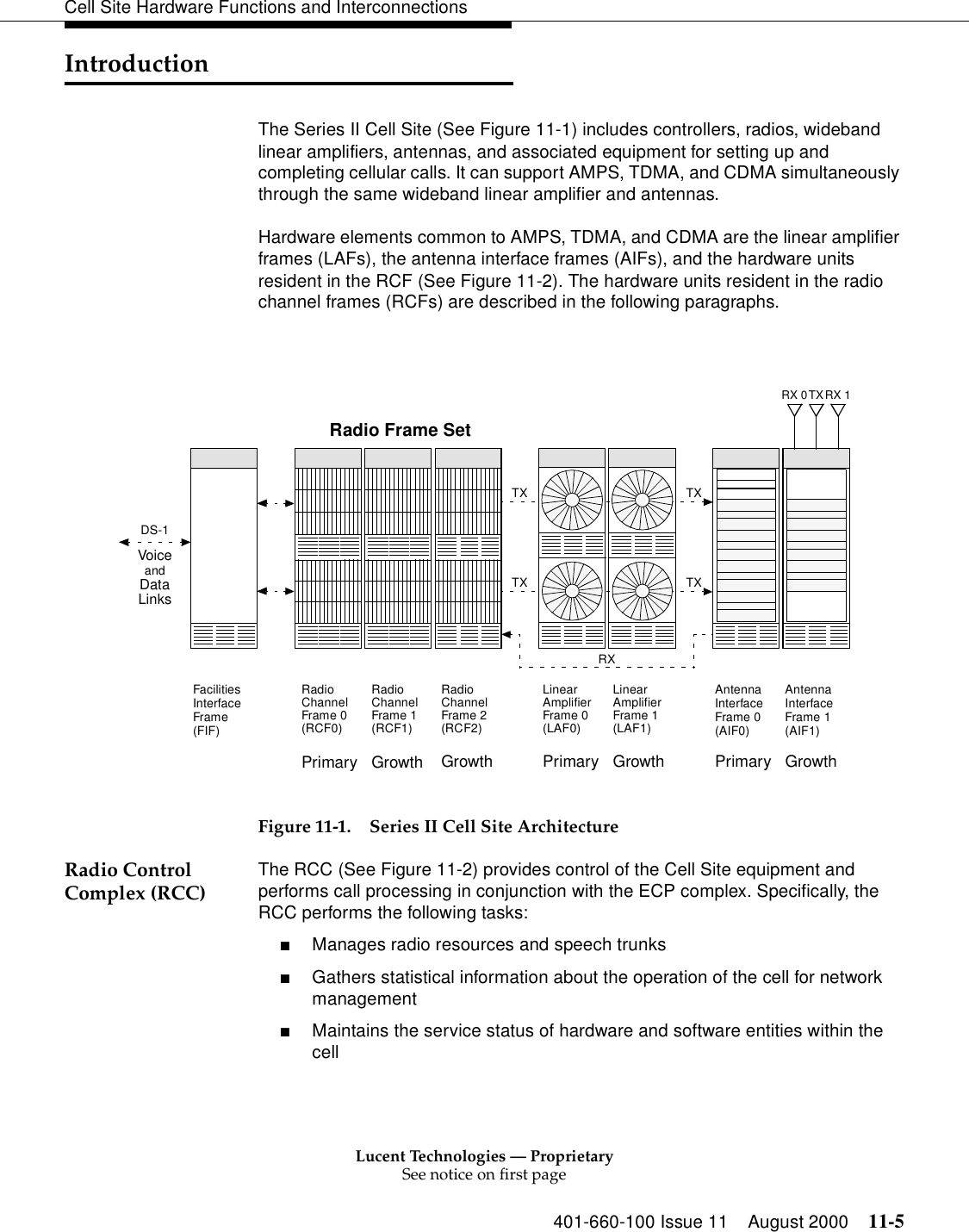
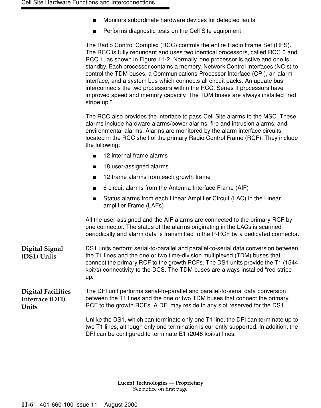
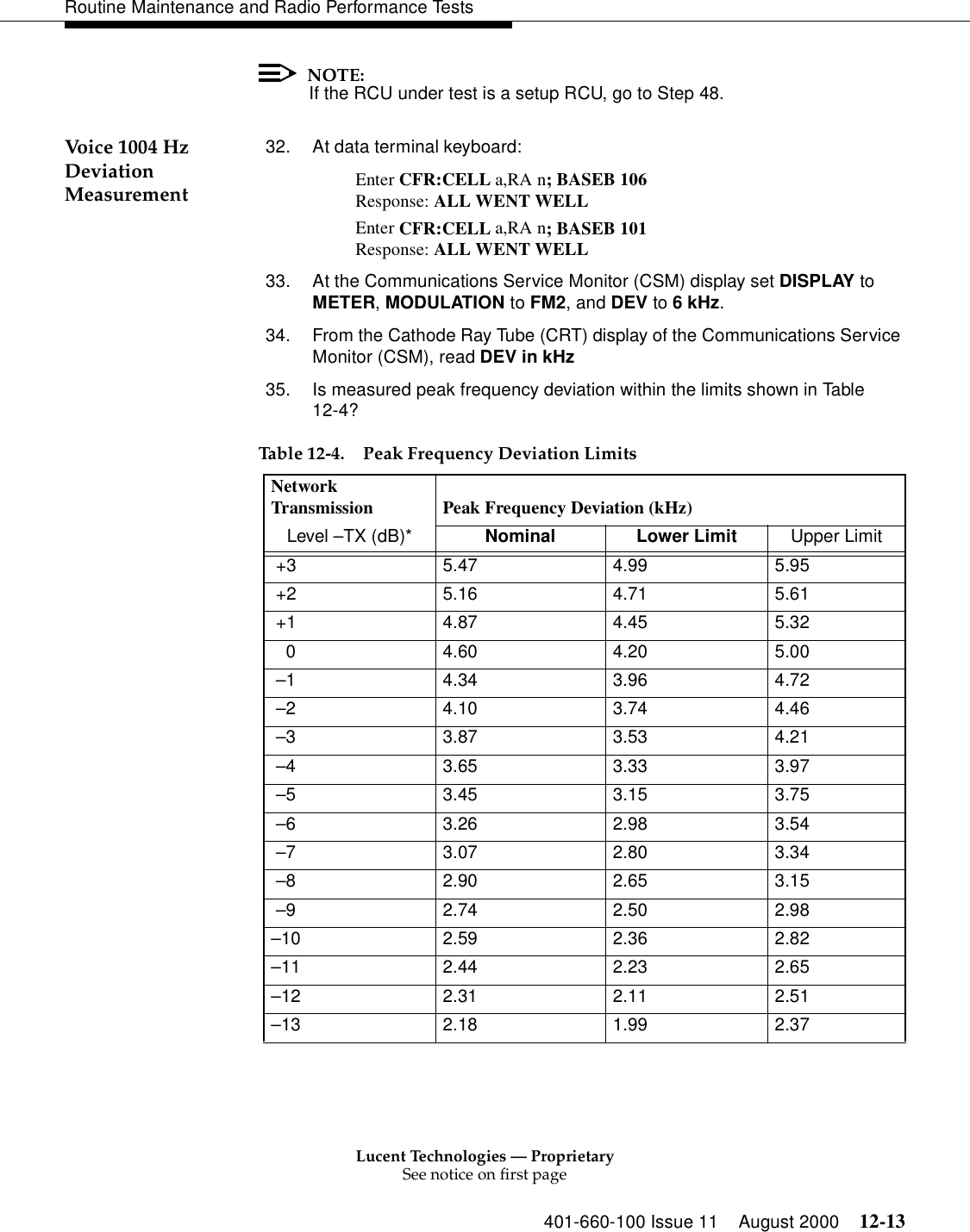
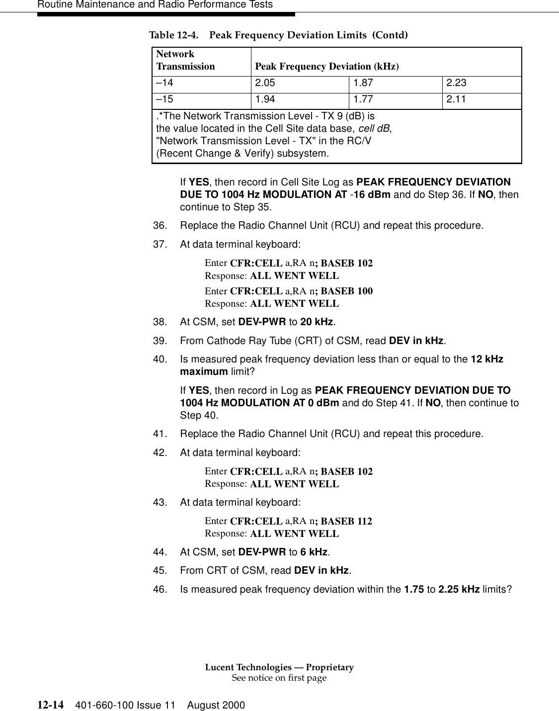
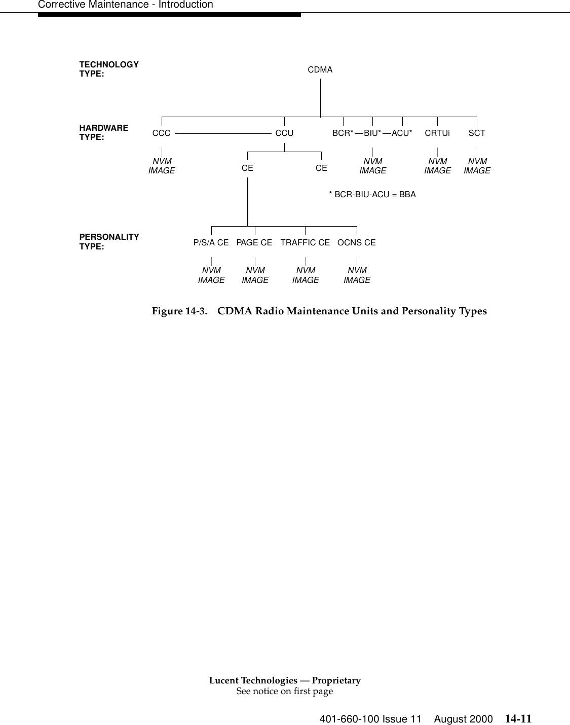
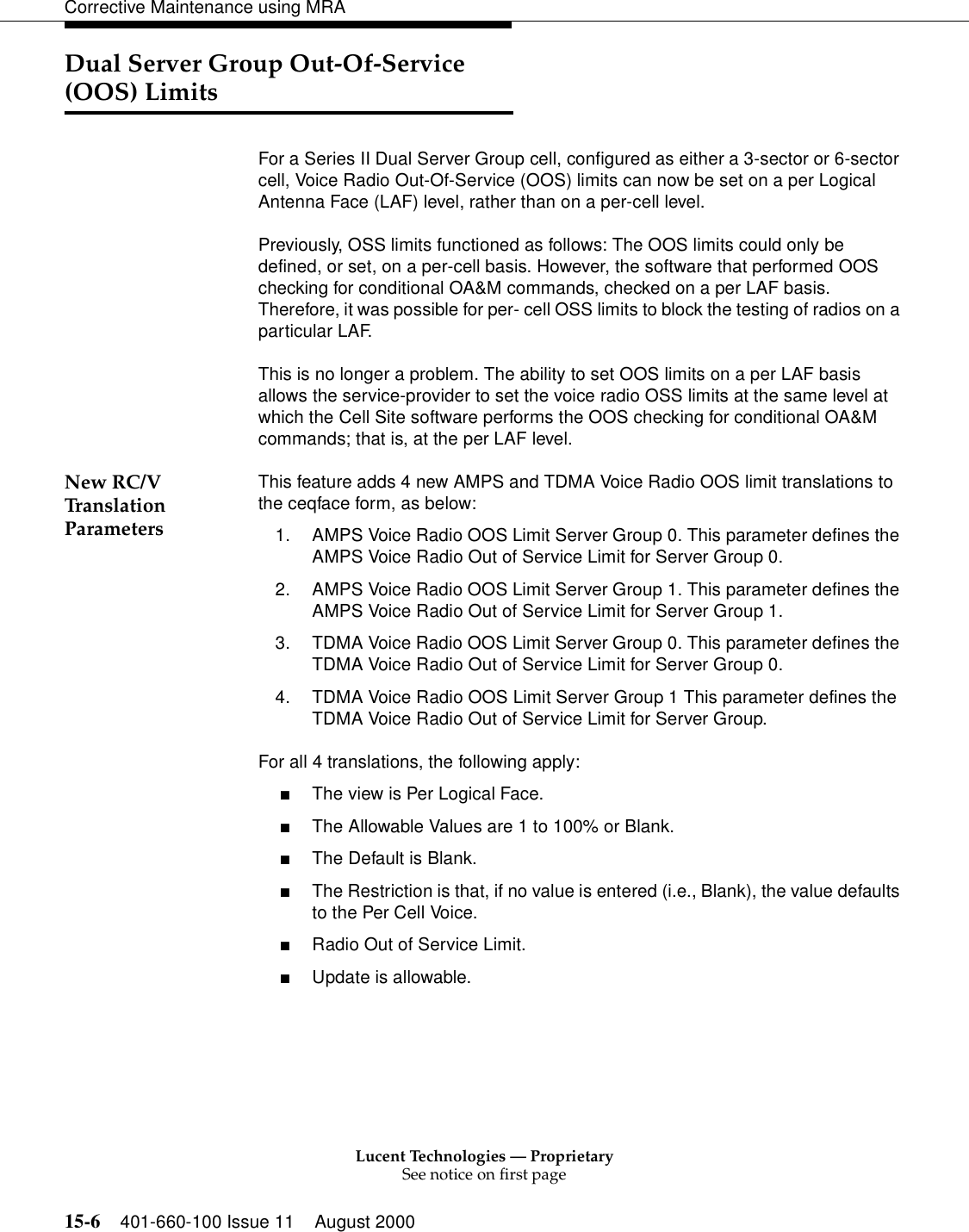
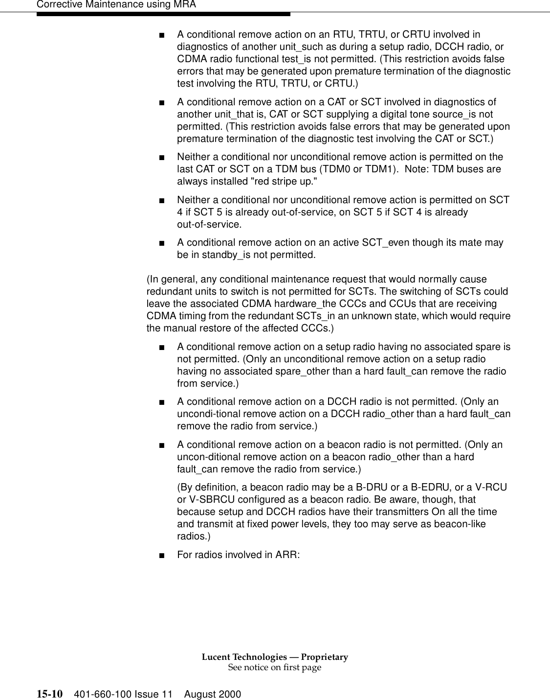
![Lucent Technologies — ProprietarySee notice on first page12-16 401-660-100 Issue 11 August 2000Routine Maintenance and Radio Performance Tests Transmitter Output Power VerificationNOTE:Output power is measured at jack J3 on the Radio Test Unit (RTU) switch panel. 1. Verify that the cell's Radio Channel Unit (RCU) equipage per transmitter [Linear Amplifier Circuit (LAC)] agrees with the Cell Site Test Record Sheets. Update the sheets with the added Digital Radio Units (DRUs). 2. Specify and verify that the DRU output power is different from the RCU. NOTE:When determining the maximum number of radios that are assigned to a LAC, each DRU should be counted as 1.5 units, and each RCU should be counted as 1.0 units. Ensure that the units added to each transmitter (LAC) does not exceed the LAC's maximum allowable output power. 1. If the Cell Site Test Record Sheet is inaccurate or missing, verify that the transmitter's (LAC) maximum allowable output power is not exceeded. Transmitter Output Power Adjustment2. 1. Connect a test cable of known loss between the CSTS RF IN/OUT jack and jack J3 on the RTU switch panel.NOTE: The CSTS is operated in the manual mode during this subsection. 3. On the CSTS at the Lucent TESTS menu, press EXIT to set the CSTS to the manual mode. While in the manual mode, perform the following procedures: a. Press RESET. b. Select and punch TO SCREEN - SPEC ANL. c. Select and punch CENTER FREQ. d. Enter 882 via the DATA keys, and press ENTER. e. Select and punch REF LEVEL. f. Enter -10 via the DATA keys, and press ENTER. g. Select and punch SPAN. h. Enter 30 via the DATA keys, and press ENTER. i. Select and punch CONTROLS - MAIN. j. Under CHOICES, select and punch AUXILIARY. k. Select and punch CONTROLS - NO PK/AVG. l. Under CHOICES, select and punch AVG 10.](https://usermanual.wiki/Alcatel-Lucent-USA/CMP-40.users-manual-2/User-Guide-161961-Page-189.png)