Alcatel Lucent USA CMP-40 Cellular Base Station Transceiver User Manual users manual 2
Alcatel-Lucent USA Inc. Cellular Base Station Transceiver users manual 2
Contents
- 1. users manual 1
- 2. users manual 2
- 3. users manual 3
users manual 2

Lucent Technologies — Proprietary
See notice on first page
8-34 401-660-100 Issue 11 August 2000
Series II Cell Site Equipment Descriptions
1 N Tx Antenna 1
2 N Tx Antenna 2
3 N Tx Antenna 3
4 N Tx Antenna 4
5 N Tx Antenna 5
6 N Tx Antenna 6
RECEIVE 0 ANTENNA INPUTS
0 N Rx 0 Antenna 0
1 N Rx 0 Antenna 1
2 N Rx 0 Antenna 2
3 N Rx 0 Antenna 3
4 N Rx 0 Antenna 4
5 N Rx 0 Antenna 5
6 N Rx 0 Antenna 6
RECEIVE 1 ANTENNA INPUTS
0 N Rx 1 Antenna 0
1 N Rx 1 Antenna 1
2 N Rx 1 Antenna 2
3 N Rx 1 Antenna 3
4 N Rx 1 Antenna 4
5 N Rx 1 Antenna 5
6 N Rx 1 Antenna 6
†These connectors are not used on the Growth RCF.
Table 8-5. Radio Channel Frame Interconnection Panel (ED-2R831-30)
Connector Identification
Jack (Plug) Conn Type Function
REFERENCE POWER DIVIDER (1:6)
REF(PD30)*
COM SMA 15 MHz Reference Input
1 SMA 15 MHz to Shelf 1 PD1
2 SMA 15 MHz to Shelf 2 PD1
Table 8-4. Radio Channel Frame Interconnection Panel (ED-2R831-30)
Connector Identification (Contd)
Jack (Plug) Conn Type Function

Lucent Technologies — Proprietary
See notice on first page
401-660-100 Issue 11 August 2000 8-35
Series II Cell Site Equipment Descriptions
3 SMA 15 MHz to Shelf 3 PD1
4 SMA 15 MHz to Shelf 4 PD1
5 SMA 15 MHz to Shelf 5 PD1
6 SMA Not Used
REFERENCE POWER DIVIDER (1:6)
REF(PD30)†
COM SMA 15 MHz Reference Input
1 SMA 15 MHz to Shelf 0 PD1
2 SMA 15 MHz to Shelf 1 PD1
3 SMA 15 MHz to Shelf 2 PD1
4 SMA 15 MHz to Shelf 3 PD1
5 SMA 15 MHz to Shelf 4 PD1
6 SMA 15 MHz to Shelf 5 PD1
* Connections for P-RCF.
† Connections for Growth RCF.
Table 8-6. Radio Channel Frame Interconnection Panel (ED-2R831-30)
Connector Identification
Jack (Plug) Conn Type Function
TRANSMIT ANTENNAS POWER COMBINERS (9:1)
0 (PD20)
J1 SMA Tx Ant 1 Test to Tx SIG MON-0
J2 thru J10 SMA
J11 SMA Tx Output
0
1 (PD21)
J1 SMA Tx Ant 1 Test to Tx SIG MON-1
J2 thru J10 SMA
J11 SMA Tx Output
1
2 (PD22)
J1 SMA Tx Ant 2 Test to Tx SIG MON-2
J2 thru J10 SMA
J11 SMA Tx Output
2
Table 8-5. Radio Channel Frame Interconnection Panel (ED-2R831-30)
Connector Identification (Contd)
Jack (Plug) Conn Type Function

Lucent Technologies — Proprietary
See notice on first page
8-36 401-660-100 Issue 11 August 2000
Series II Cell Site Equipment Descriptions
3 (PD23)
J1 SMA Tx Ant 3 Test to Tx SIG MON-3
J2 thru J10 SMA
J11 SMA Tx Output
3
4 (PD24)
J1 SMA Tx Ant 4 Test to Tx SIG MON-4
J2 thru J10 SMA
J11 SMA Tx Output
4
5 (PD25)
J1 SMA Tx Ant 5 Test to Tx SIG MON-5
J2 thru J10 SMA
J11 SMA Tx Output
5
6 (PD26)
J1 SMA Tx Ant 6 Test to Tx SIG MON-6
J2 thru J10 SMA
J11 SMA Tx Output
6
Table 8-7. Radio Channel Frame Interconnection Panel (ED-2R831-30,
Connector Identification
Jack (Plug) Conn Type Function
REF TNC 15 MHz Reference Input
SET UP 0† N Set Up Antenna (for future use)
RTU IN† N Radio Test Unit Input
RTU OUT† N Radio Test Unit Output
TRANSMIT ANTENNA OUTPUTS
0 N Tx Antenna 0
1 N Tx Antenna 1
2 N Tx Antenna 2
3 N Tx Antenna 3
4 N Tx Antenna 4
5 N Tx Antenna 5
6 N Tx Antenna 6
Table 8-6. Radio Channel Frame Interconnection Panel (ED-2R831-30)
Connector Identification (Contd)
Jack (Plug) Conn Type Function

Lucent Technologies — Proprietary
See notice on first page
401-660-100 Issue 11 August 2000 8-37
Series II Cell Site Equipment Descriptions
RECEIVE 0 ANTENNA INPUTS
0 N Rx 0 Antenna 0
1 N Rx 0 Antenna 1
2 N Rx 0 Antenna 2
3 N Rx 0 Antenna 3
4 N Rx 0 Antenna 4
5 N Rx 0 Antenna 5
6 N Rx 0 Antenna 6
RECEIVE 1 ANTENNA INPUTS
0 N Rx 1 Antenna 0
1 N Rx 1 Antenna 1
2 N Rx 1 Antenna 2
3 N Rx 1 Antenna 3
4 N Rx 1 Antenna 4
5 N Rx 1 Antenna 5
6 N Rx 1 Antenna 6
†These connectors are not used on the Growth RCF.
Table 8-8. Radio Channel Frame Interconnection Panel (ED-2R831-30,)
Connector Identification
Jack (Plug) Conn Type Function
RECEIVE 0 ANTENNAS POWER DIVIDERS (1:9)
0 (PD1)
J1 SMA Not Used
J2 thru J10 SMA
J11 SMA Rx 0 Input from 0
1 (PD2)
J1 SMA Not Used
J2 thru J10 SMA
J11 SMA Rx 0 Input from 1
2 (PD3)
J1 SMA Not Used
Table 8-7. Radio Channel Frame Interconnection Panel (ED-2R831-30,
Connector Identification (Contd)
Jack (Plug) Conn Type Function

Lucent Technologies — Proprietary
See notice on first page
8-38 401-660-100 Issue 11 August 2000
Series II Cell Site Equipment Descriptions
J2 thru J10 SMA
J11 SMA Rx 0 Input from 2
3 (PD4)
J1 SMA Not Used
J2 thru J10 SMA
J11 SMA Rx 0 Input from 3
4 (PD5)
J1 SMA Not Used
J2 thru J10 SMA
J11 SMA Rx 0 Input from 4
5 (PD6)
J1 SMA Not Used
J2 thru J10 SMA
J11 SMA Rx 0 Input from 5
6 (PD7)
J1 SMA Not Used
J2 thru J10 SMA
J11 SMA Rx 0 Input from 6
Table 8-9. Radio Channel Frame Interconnection Panel (ED-2R831-30,)
Connector Identification
Jack (Plug) Conn Type Function
RECEIVE 1 ANTENNAS POWER DIVIDERS (1:9)
0 (PD11)
J1 SMA Not Used
J2 thru J10 SMA
J11 SMA Rx 1 Input from 0
1 (PD12)
J1 SMA Not Used
J2 thru J10 SMA
J11 SMA Rx 1 Input from 1
2 (PD13)
Table 8-8. Radio Channel Frame Interconnection Panel (ED-2R831-30,)
Connector Identification (Contd)
Jack (Plug) Conn Type Function
Lucent Technologies — Proprietary
See notice on first page
401-660-100 Issue 11 August 2000 8-39
Series II Cell Site Equipment Descriptions
Series II Cell Site
Busbar Assembly
Unit, KS24355, L1
The Cell Site Busbar Assembly Unit utilizes plug-in Circuit Breakers for 5.0 A, 15.0
A, and 25.0 A. It also uses screw-in Capacitors. This unit equips the growth RCF
so that it can support 8 EDRUs per shelf.
The Growth Channel Frame Hardware is listed in the table below.
J1 SMA Not Used
J2 thru J10 SMA
J11 SMA Rx 1 Input from 2
3 (PD14)
J1 SMA Not Used
J2 thru J10 SMA
J11 SMA Rx 1 Input from 3
4 (PD15)
J1 SMA Not Used
J2 thru J10 SMA
J11 SMA Rx 1 Input from 4
5 (PD16)
J1 SMA Not Used
J2 thru J10 SMA
J11 SMA Rx 1 Input from 5
6 (PD17)
J1 SMA Not Used
J2 thru J10 SMA
J11 SMA Rx 1 Input from 6
Note: For other transmit and receive options, refer to SD-2R263-
01 (P-RCF) or SD-2R264-01 (Growth RCF).
Table 8-9. Radio Channel Frame Interconnection Panel (ED-2R831-30,)
Connector Identification (Contd)
Jack (Plug) Conn Type Function
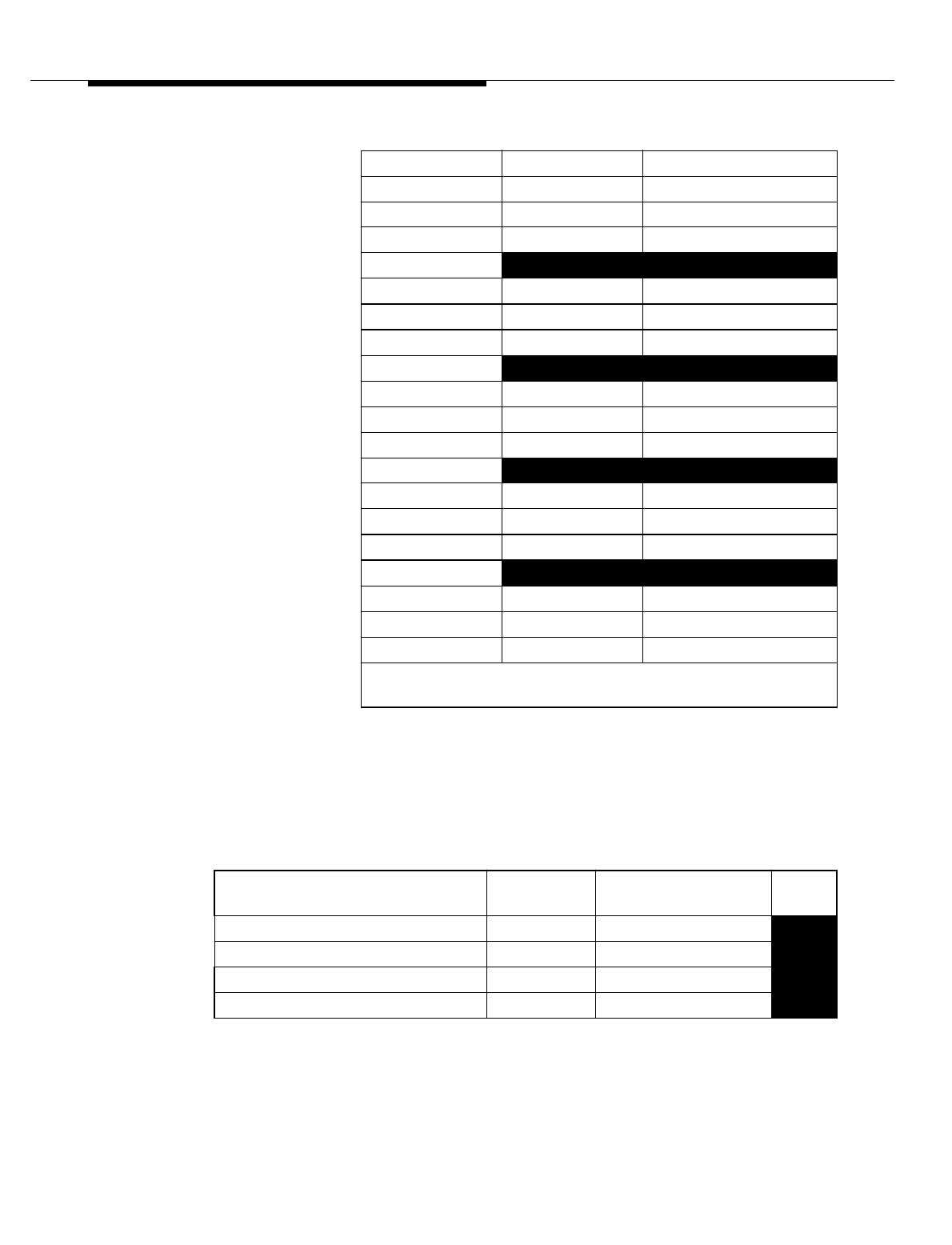
Table 8-10. Growth Radio Channel Frame (G-RCF) J41660B-2 Hardware
Item Max
Qty Code Eqpt
Loc
Cable Tray Assembly 1
Interconnection Panel 1 ED-2R831-30
Tx, Rx Power Dividers (9:1) 21 KS24235, L5
Tx, Rx Power Dividers (1:6) KS24235, L6

Lucent Technologies — Proprietary
See notice on first page
8-40 401-660-100 Issue 11 August 2000
Series II Cell Site Equipment Descriptions
Radio Channel Unit Shelf (Shelf 0-5) 6 ED-2R834-30 13, 21
Transmit Combiner 1 BBN2B
+12V Power Converter 1 419AE
Radio Channel Unit 12 ED-2R836-30
Digital Radio Unit 6 ED-2R920-30
Power Converter Unit 430AB
(Req’d for EDRU)
Enhanced Digital Radio Unit Maximum 12
per shelf 44WR8
Digital Facilities Interface (DFI) 1 TN1713B or TN3500B
+5V Converter 1 430AB
Receive Switch Divider (Manual) 2 BBN1
*Busbar Assembly Unit
(Manufactured 5/98 or later) 2 KS24355, L1
Circuit Breaker, Plug-In, 15.0 A 2 KS24356, L6
Circuit Breaker, Plug-In, 25.0 A 10 KS24356, L8
Circuit Breaker, Plug-In, 5.0 A 3 KS24356, L4
Note: This table is for hardware identification only. Do not use this table for ordering
hardware items.
* Replaces Circuit Breaker Assembly ED-2R826-30
and Capacitor Panel Assembly ED-2R829-30.
Table 8-10. Growth Radio Channel Frame (G-RCF) J41660B-2 Hardware
Item Max
Qty Code Eqpt
Loc

Lucent Technologies — Proprietary
See notice on first page
401-660-100 Issue 11 August 2000 8-41
Series II Cell Site Equipment Descriptions
Series II Mobile Switching Center
(MSC) Interface
Two data links provide the control and reporting interface between the Cell Site
and Mobile Switching Center (MSC). Either data link can control Cell Site
functions through the Radio Control Complex (RCC). Each data link interfaces
both of the processors located on the RCC. Only one processor is on-line at a
time. The other is in a standby mode, tracking functions being performed by the
on-line processor, in the event it is required to come on-line.
The on-line processor sends and receives control and data information over the
Time Division Multiplexed (TDM) bus, which is always installed "red stripe up."
Functions performed by the Cell Site units are controlled over the TDM bus. The
on-line processor also supplies data and control to each of the Radio Channel
Unit (RCUs).
Series II Cell Site architecture consists of three types of equipment frames:
1. Radio Channel Frame (RCF) — Primary and a maximum of two growth
frames
2. Linear Amplifier Frame (LAF) — Two frames, maximum
3. Antenna Interface Frame (AIF) — Two frames, maximum.
The P-RCF contains the Radio Channel Complex (RCC) as well as the shelves for
individual TDMA radios. The RCC controls the operation of the Cell Site
equipment. The LAF provides RF signal combining and amplification equipment,
while the AIF houses the Cell Site's reference frequency generator, receiver
calibration generator, and the RF filter networks that transport the RF signal to
and from the antennas.
A Radio Frame Set (RFS) consists of one, two, or three RCFs, all controlled by
one RCC. There will be one or two LAFs and one or two AIFs per Cell Site. Note
that each of the three RCFs may contain Digital Radio Units (DRUs) or Enhanced
Digital Radio Units (EDRUs). The DRU or EDRU is the radio unit used with Series
II TDMA. The DRU can be configured as a Voice radio (V-DRU) or a Locate radio
(L-DRU). One DRU occupies two analog Radio Channel Unit (RCU) slots and
provides three Digital Traffic Channels (DTCs). One EDRU occupies a single RCU
slot and also provides three DTCs. The EDRU can be configured as a Control/
Traffic (C/T-EDRU) or as an L-EDRU.
Series II analog hardware frames. DRUs, EDRUs, and the TDMA radio hardware,
can reside in the same Series II Cell Site RCFs as the analog 30-kHz RCUs.
Hardware wise, converting from Series II Cell Site with analog radios to Series II
TDMA radios is quite simple. For Series II TDMA, the plug-in DRUs and EDRUs
Lucent Technologies — Proprietary
See notice on first page
8-42 401-660-100 Issue 11 August 2000
Series II Cell Site Equipment Descriptions
are added in the existing radio slots in the RFS. Note that it takes two RCU slots
for each DRU.
However, one DRU using a single carrier frequency supports three channels,
while the RCU (analog unit) using a single carrier frequency supports only one
channel. Note also, that an EDRU can perform all the same functions, and more,
of a DRU and takes up only one RCU slot. DRUs and EDRUs may be added to the
Series II Cell Site by replacing existing RCUs with DRUs or EDRUs. Additionally,
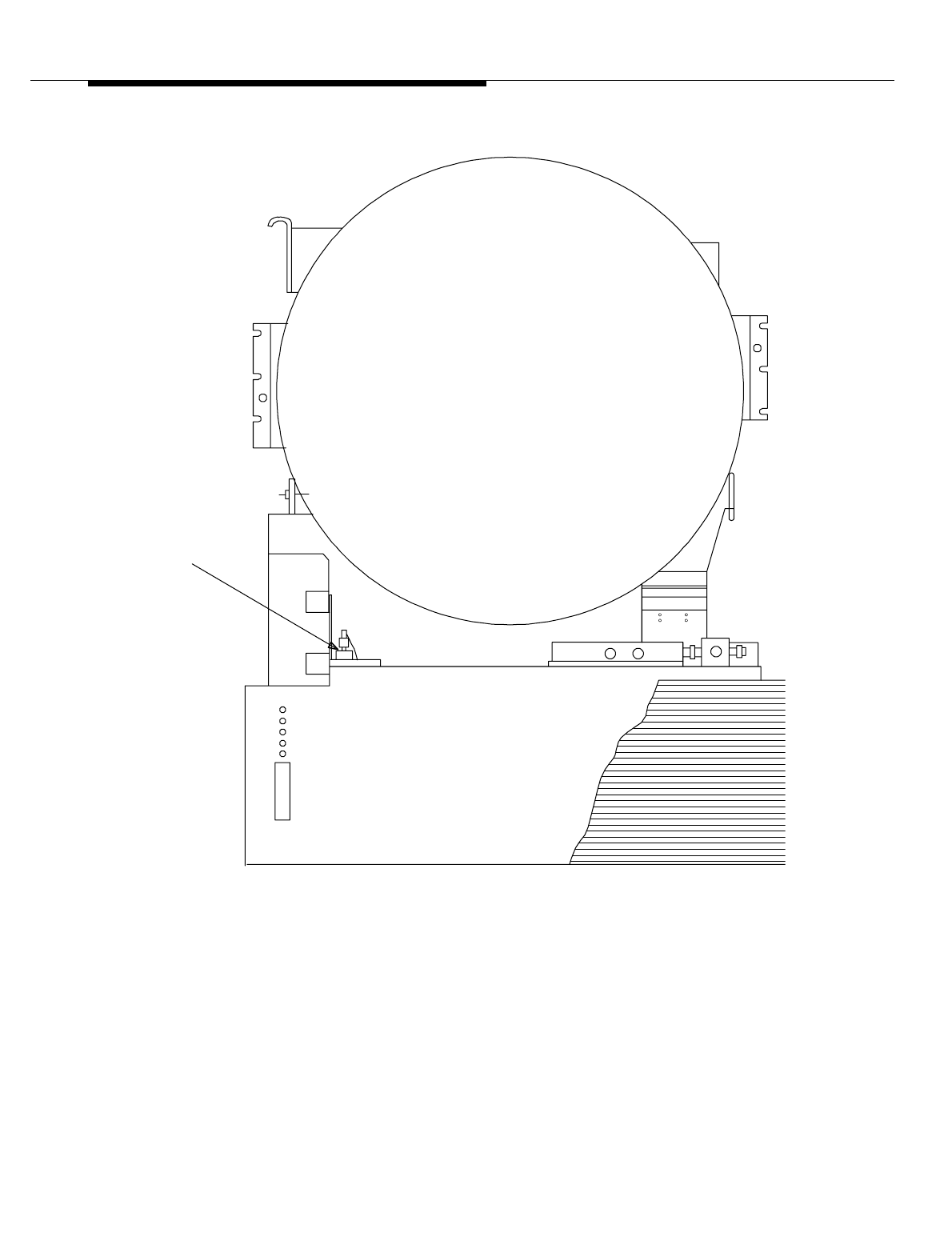
one TDMA Radio Test Unit (TRTU) and one (analog) Radio Test Unit (RTU)
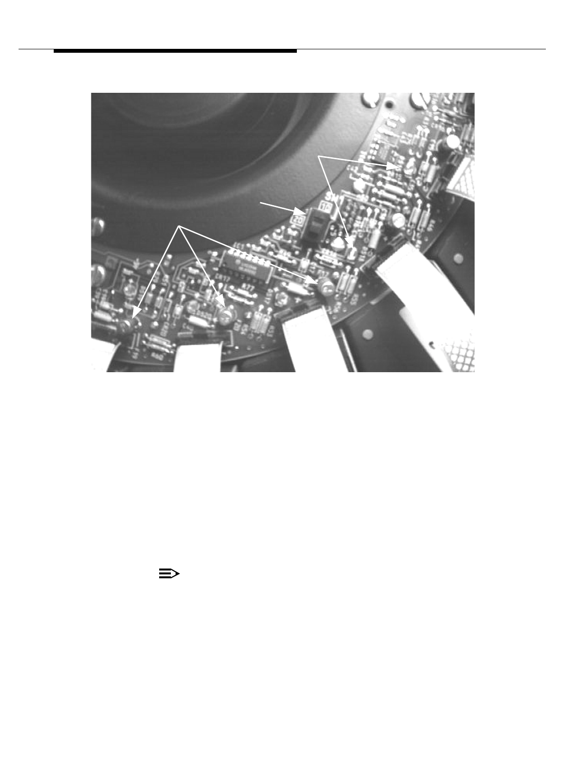
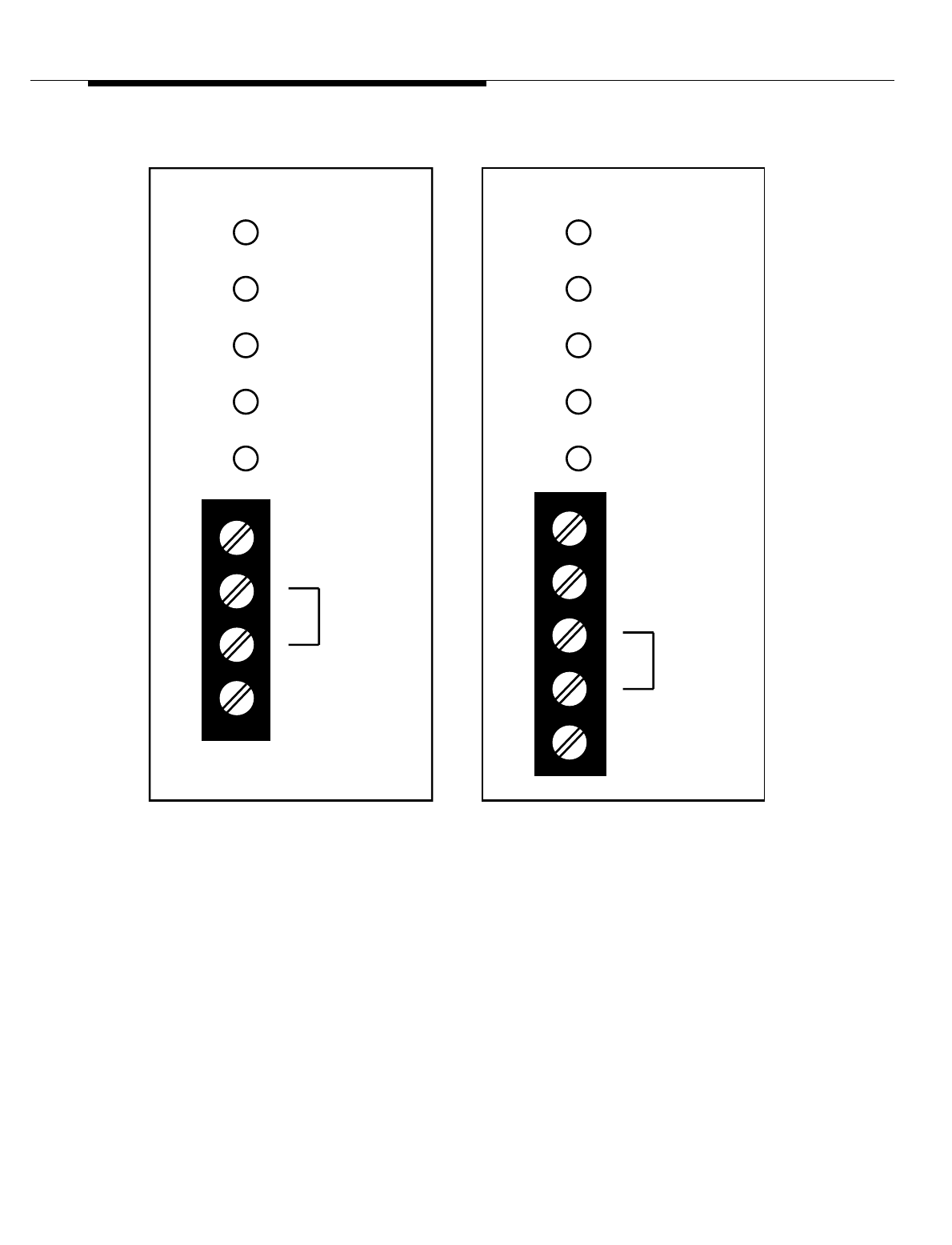
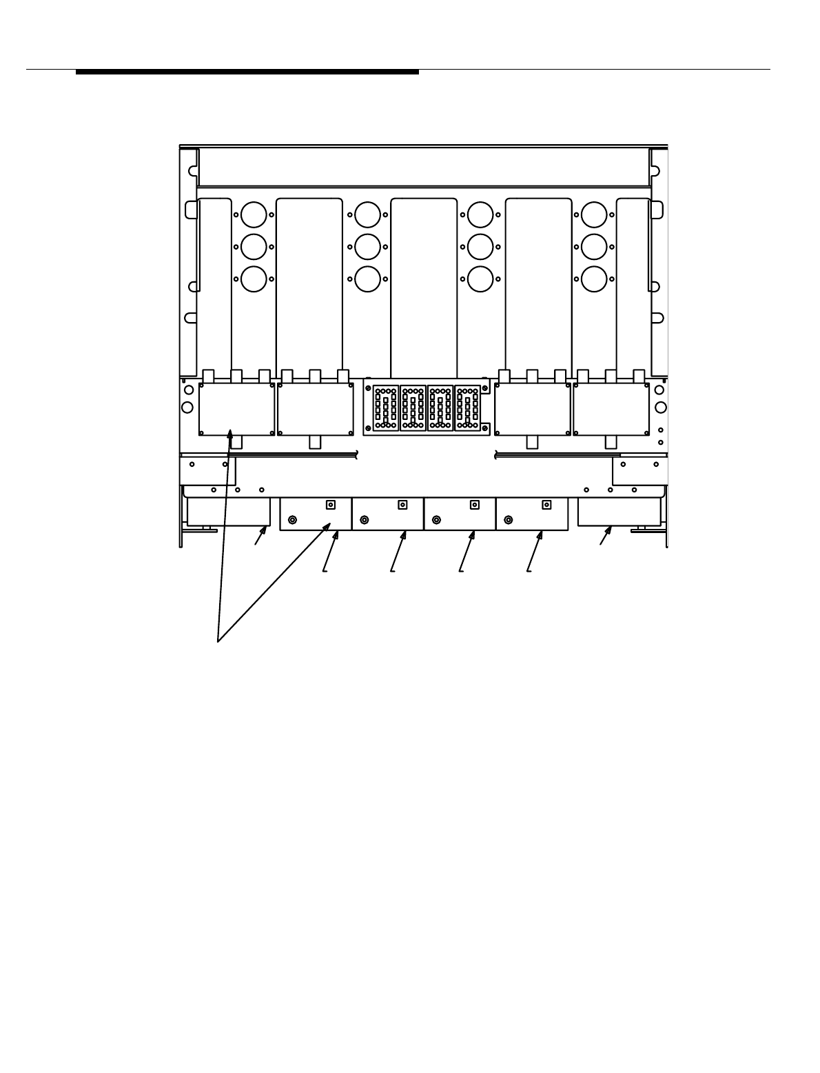
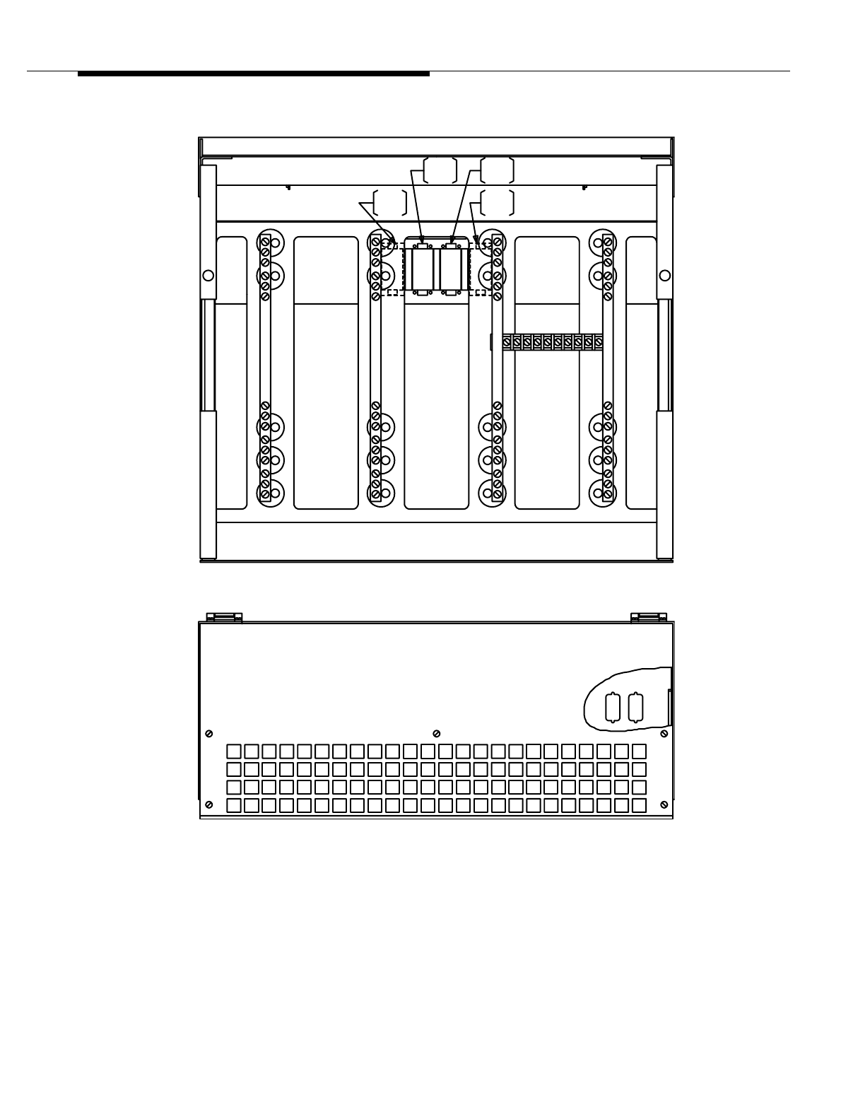
Control Board (see Figure 8-12) are required for each digitally equipped Cell Site.
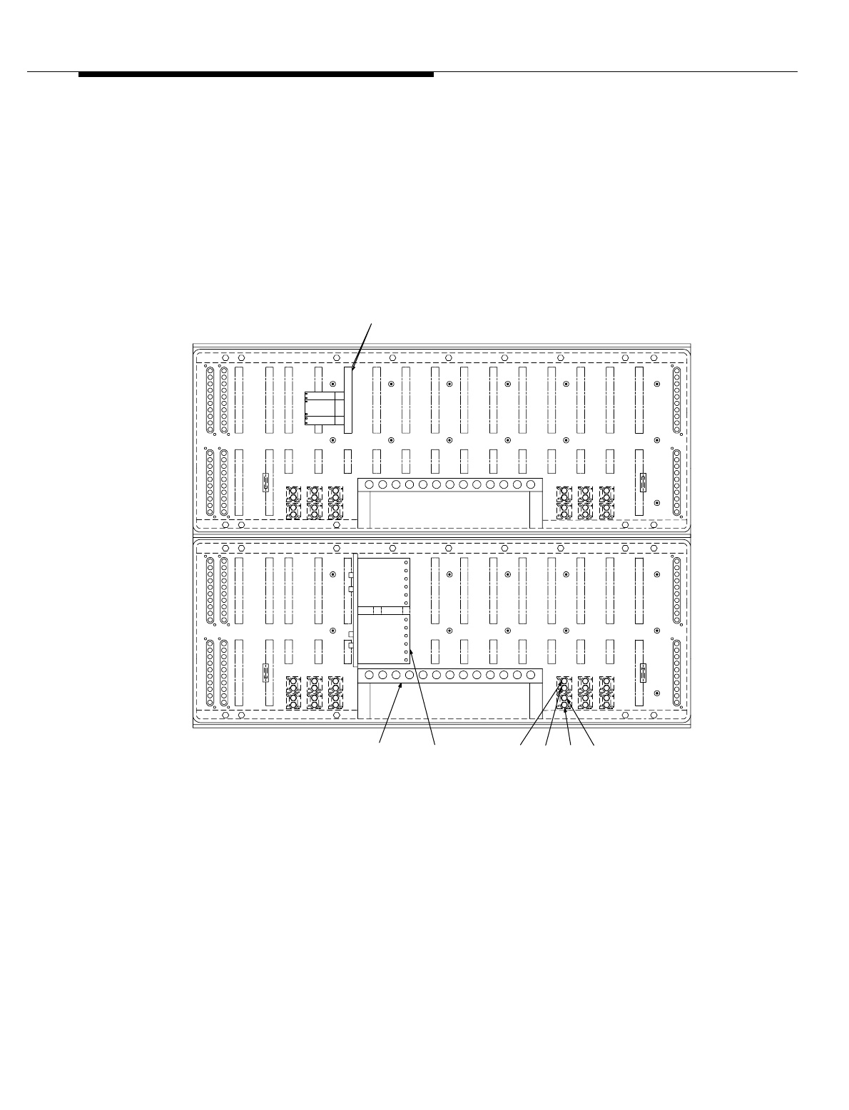
Figure 8-12. Radio Test Unit (RTU) Control Board (AYD8) and Switch
Assembly (ED3R026-30) Location
The Series II Cell Site is based on a modular architecture. It includes controllers,
radios, wideband linear amplifiers, antennas, and associated equipment for
REAR VIEW
EQL 012EQL 162
EQL 012EQL 162
RCU/DRU
REF FREQ.
RTU
SWITCH
RCU
TRANSMIT
RCU
REF.
FREQ.
RCU
REC1
RCU
REC0
LEVEL 30
(SHELF 30
LEVEL 21
(SHELF 4)
RTU
CONTROL
BOARD
RTN
+V 123444
RTN
+V 1 2 3

Lucent Technologies — Proprietary
See notice on first page
401-660-100 Issue 11 August 2000 8-43
Series II Cell Site Equipment Descriptions
setting up and completing cellular calls. It can support AMPS, TDMA, and CDMA
simultaneously through the same wideband linear amplifier and antennas.
The AMPS radio consists of a single plug-in unit—the radio channel unit (RCU) or
the single-board RCU (SBRCU); either unit occupies one RCU slot. (The RCU
consists of two circuit boards, and the SBRCU consists of a single circuit board.
The RCU faceplate is wider than the SBRCU faceplate.) Similarly, the TDMA radio
consists of a single plug-in unit, the digital radio unit (DRU) or the enhanced digital
radio unit (EDRU); the DRU occupies two adjoining RCU slots, and the EDRU
occupies one RCU slot. In contrast, the CDMA radio consists of an entire shelf of
plug-in units.

Lucent Technologies — Proprietary
See notice on first page
8-44 401-660-100 Issue 11 August 2000
Series II Cell Site Equipment Descriptions
Series II Cell Site Linear Amplifier
Frame (LAF)
The major units of the Linear Amplifier Frame (LAF) are listed below and
described in the paragraphs that follow:
■Frame Interface Assembly (FIA)
■Linearizer Unit (LZR)
■Linear Amplifier Unit (LAU).
The Linear Amplifier Frame (LAF) is designated as J41660C-1, C-2. All Cell Sites
have at least one LAF with at least one Linear Amplifier Circuit (LAC). Two
different (M)LACs are available depending on the output power needed. They are:
1. 100-Watt (M)LAC uses 10 Linear Amplifier Modules (LAMs).
2. 240-Watt (M)LAC uses 20 LAMs.
Three additional LACs may be configured as needed. A fully loaded LAF (LAF 0)
may contain up to four LACs. An additional LAF, may be added and may be
equipped with up to three LACs.
.
Table 8-11. Linear Amplifier Frame (LAF) Hardware
Item Max
Qty Code Eqpt
Loc
Linear Amplifier Frame 0 (Primary) 1 J41660C-1, C-2
Sniffer Combiner (For CDPD) 1 KS21604, L22A
Frame Interface Assembly 1 ED-2R838-30 70
Box Fan 2 WP92103, L1
Linear Amplifier Circuit (LAC) J-41660CA-2, L6 (Full)
Linear Amplifier Circuit (LAC) J-41660CA-2, L5
(Half)
Modular Linear Amplifier Circuit
(MLAC) J-41660CA-3
RF Amplifier 1 KS23757, L1
Fan Blower 1 WP92104, L1
Linear Amplifier Module‡ 10 or
20 ED-2R840-30
* Up to three additional LACs can be provided in LAF 1.
Lucent Technologies — Proprietary
See notice on first page
401-660-100 Issue 11 August 2000 8-45
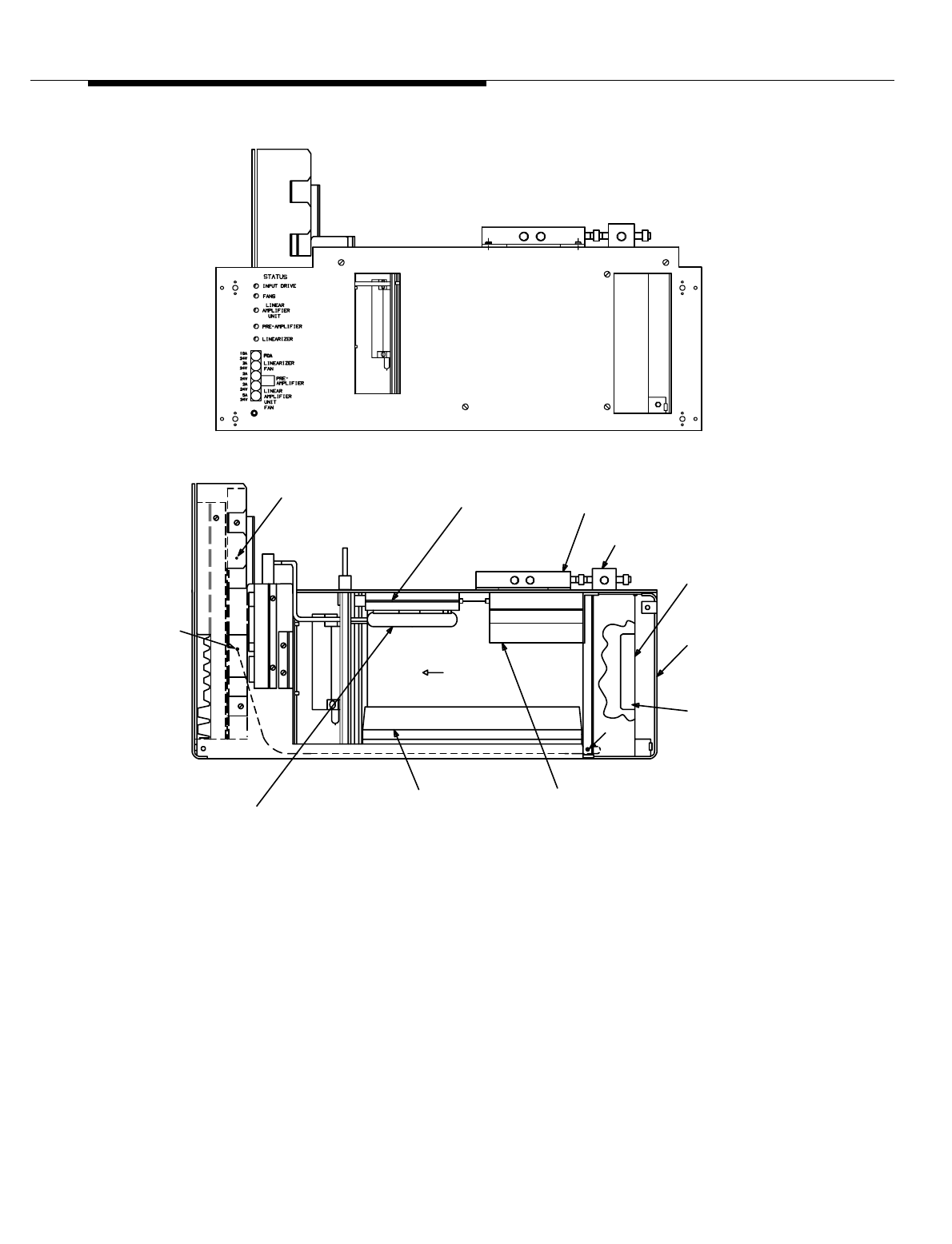
Series II Cell Site Equipment Descriptions
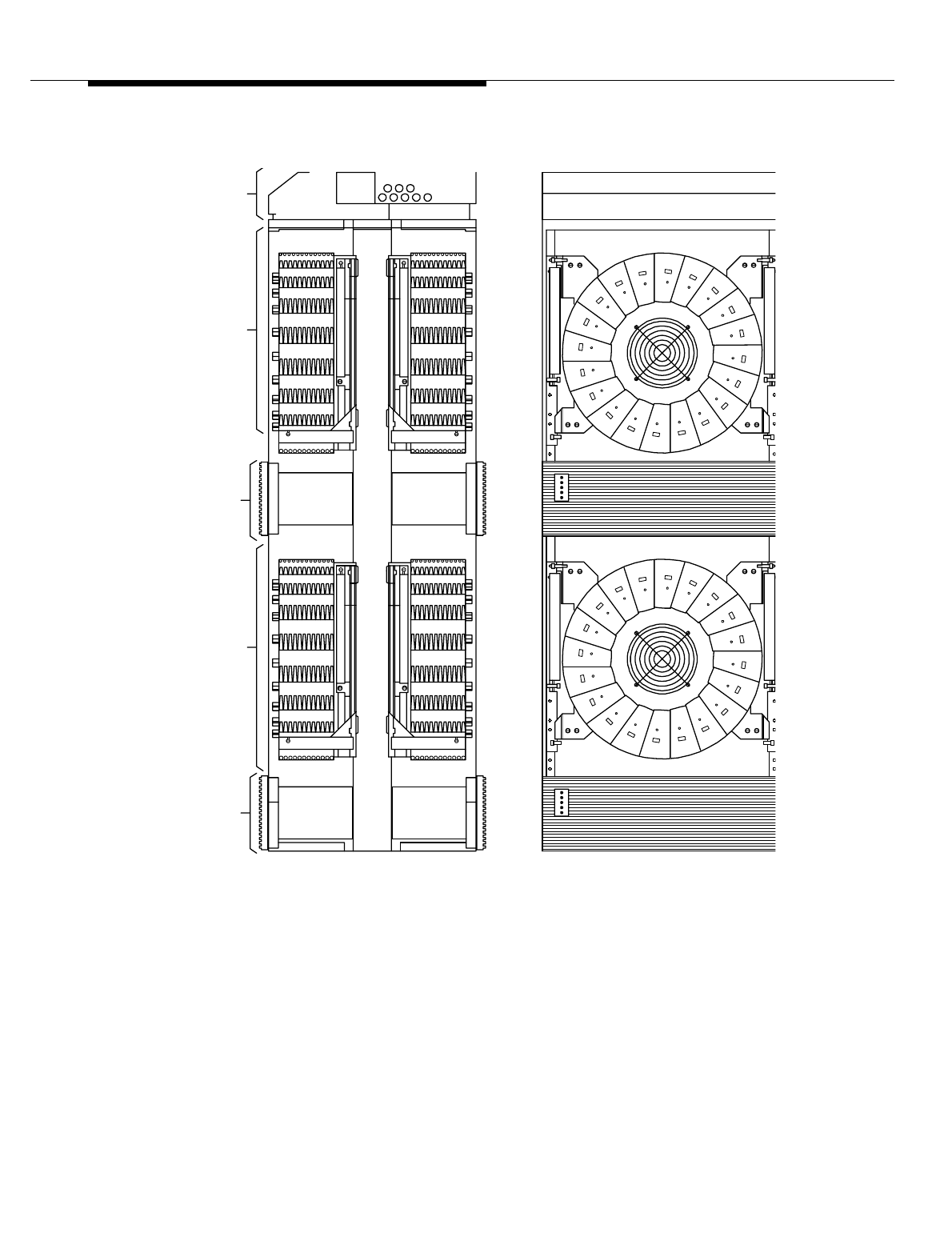
Figure 8-13. Linear Amplifier Frame (LAF) (J41660C-1)
LEVEL
28
LEVEL
10
FRONT VIEWSIDE VIEW
LINEARIZER
LINEARIZER
AMPLIFIER
LINEAR
FRAME
INTERFACE
ASSEMBLY
AMPLIFIER
LINEAR
LEVEL
19
LEVEL
54
LEVEL
70
UNIT
UNIT
Lucent Technologies — Proprietary
See notice on first page
8-46 401-660-100 Issue 11 August 2000
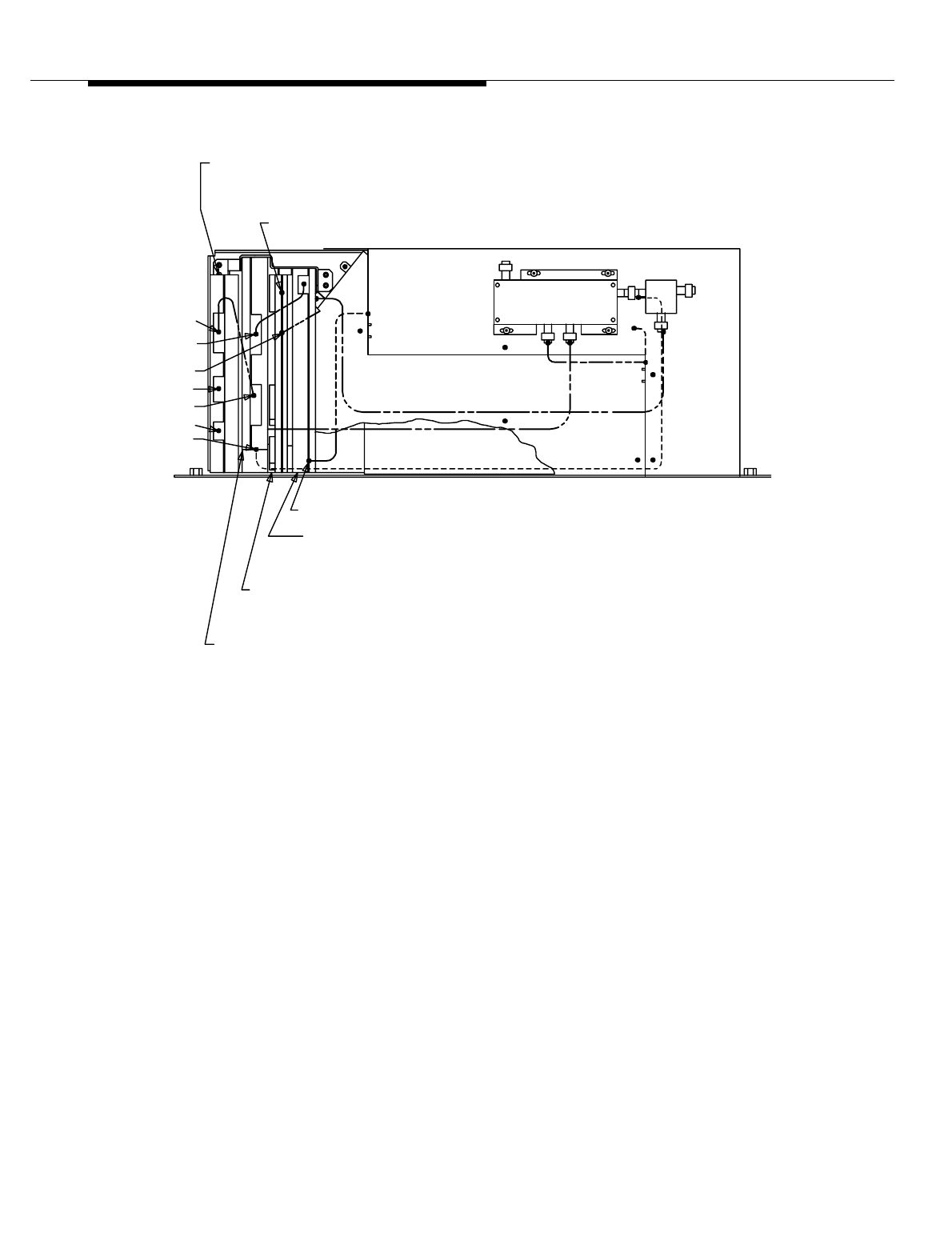
Series II Cell Site Equipment Descriptions
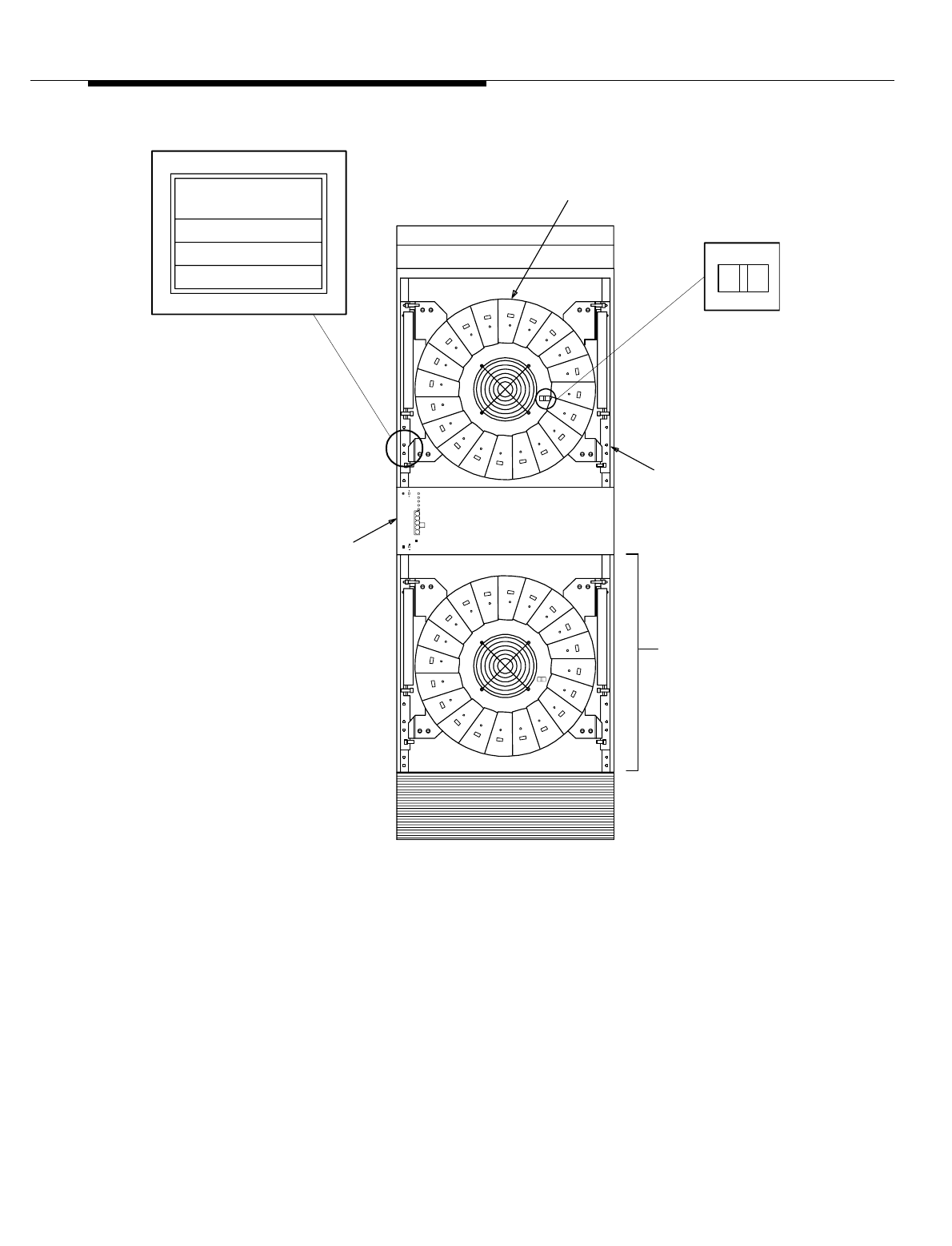
Figure 8-14. Linear Amplifier Frame (LAF) (Doors Removed)
Series II Cell Site
Linear Amplifier
Circuit J41660CA-1
The Linear Amplifier Unit (ED-2R839-30) and the Linearizer Unit (ED-2R841-30)
make up a Linear Amplifier Circuit (LAC) (see Figure 8-15). Up to four LACs may
be used. The Linear Amplifier Unit (LAU) has either 10 or 20 pie-shaped Linear
Amplifier Modules (ED-2R840-30) operating in parallel. When all Linear Amplifier
Modules (LAMs) are equipped, the maximum average output power is 240 watts.
LINEAR
AMPLIFIER
20
10
20
10
UNIT (LAU)
SWITCH
(SET TO 10
FOR 10 LAMs,
SET TO 20
FOR 20 LAMs)
LINEAR AMPLIFIER
FRAME (LAF)
LINEARIZER (LZR)
(COVER REMOVED)
CONVERSION RECORD
#LAM DATE CONVERTED
10
20
10
LABEL (MARK DATE
CONVERTED TO 10 LAM
OR 20 LAM LAC)
LINEAR AMPLIFIER
CIRCUIT (LAC)

Lucent Technologies — Proprietary
See notice on first page
401-660-100 Issue 11 August 2000 8-47
Series II Cell Site Equipment Descriptions
The LAU has a power distribution board (AYM1), a 24-volt power filter, a cooling
fan, and a temperature sensor. The output from the LAU is applied to the antenna
interface frame. A splitter combiner assembly is also part of the LAU.
The term Linear Amplifier Circuit (LAC) (see Figure 8-16) is used to include all
major functional parts of the Linear Amplifier Frame (LAF). The LAC provides high
power amplification of many transmit signals and controls the intermodulation
distortion. The LAC consists of the following:
■Combiner-Preamplifier Circuit
■Linear Amplifier Unit (LAU)
■Linearizer (LZR).
Transmit signals originating at the RCF(s) are combined and amplified to a level
suitable for driving the input of the LZR. The LZR uses feed-forward, pre-
distortion, and amplification of the input signal to cancel distortion and provides a
level necessary for driving the LAU. The LZR provides continuous control of gain
and phase to provide maximum distortion reduction. It also provides fault
detection, power distribution, and overload protection for the LAC.
The LAU consists of 10 or 20 LAMs arranged in parallel, a splitter-combiner
network, and a power distribution board. It amplifies the input signal to an output
level of 240 watts when fully configured with 20 LAMs (approximately 120 watts
when equipped with 10 LAMs). The +24 volt DC from the Cell Site power plant is
applied to the filter capacitor bank in the FIA. From here, power feeders 0 through
3 supply +24 volt DC to the LAU and power feeder 4 supplies +24 volt DC to the
LZR fan and to the Power Fault Monitor (PFM) board inside the LZR.
Lucent Technologies — Proprietary
See notice on first page
8-48 401-660-100 Issue 11 August 2000
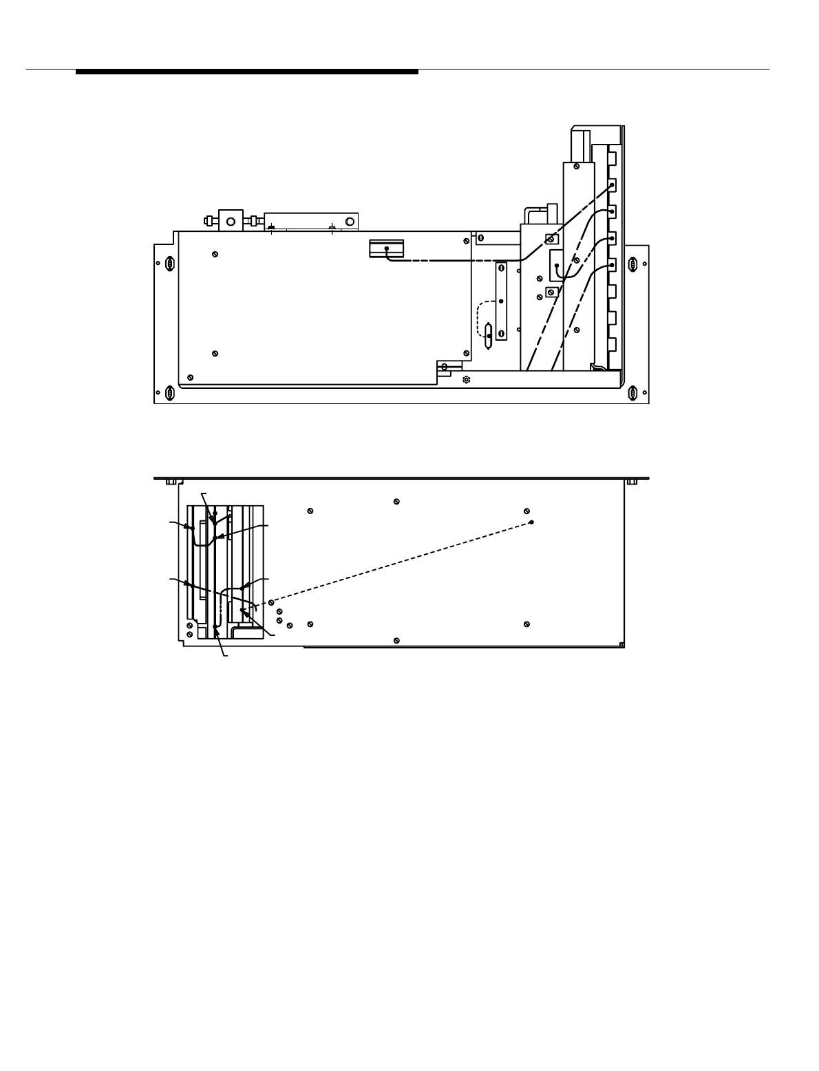
Series II Cell Site Equipment Descriptions
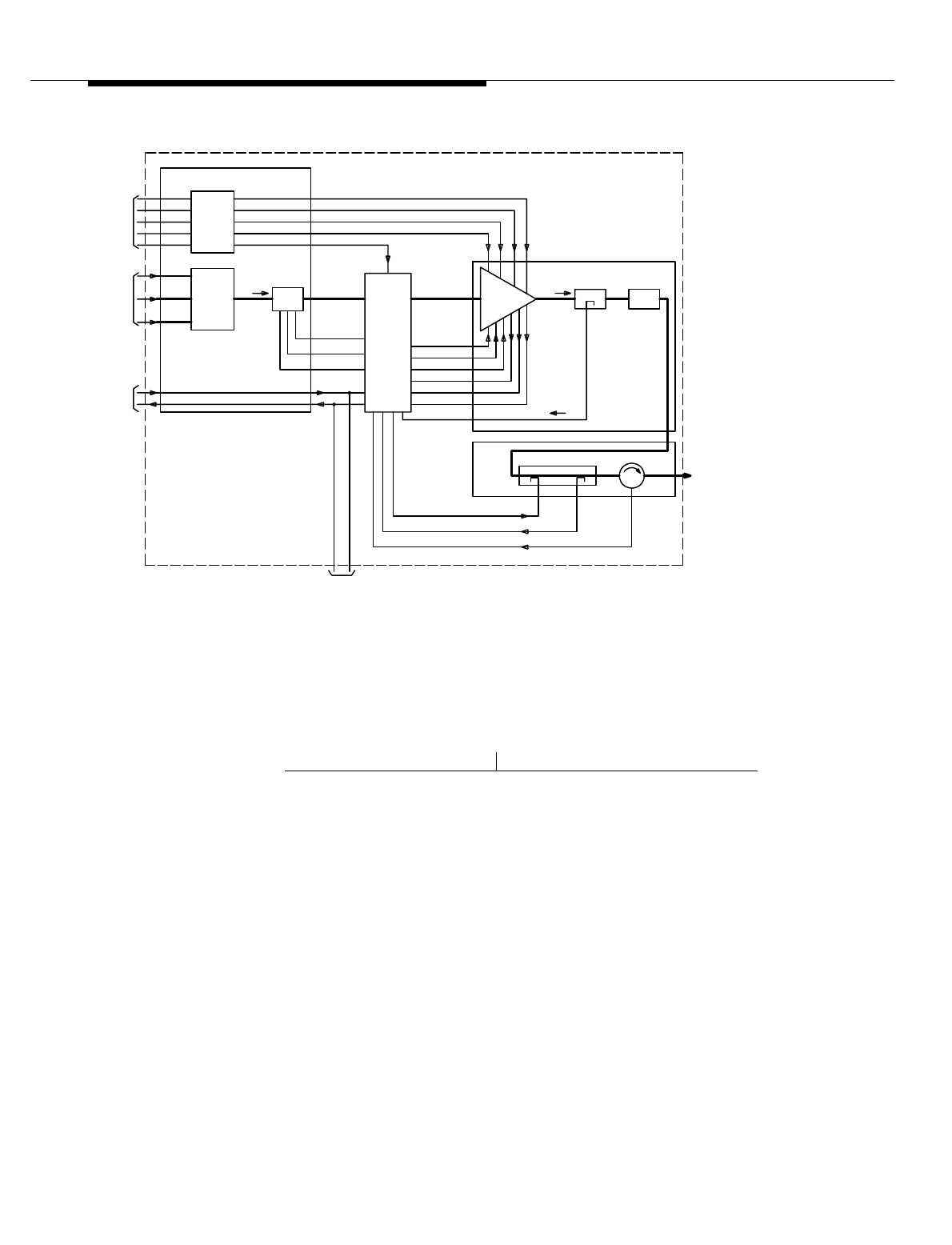
Figure 8-15. Linear Amplifier Circuit (LAC), Front View
The PFM board supplies +24 volt DC to the fan in the LAU; it also converts the
+24 volt DC to +5 and ±15 volt DC and applies these to the LAU.
YF4

Lucent Technologies — Proprietary
See notice on first page
401-660-100 Issue 11 August 2000 8-49
Series II Cell Site Equipment Descriptions
The PFM board distributes the gain and phase adjustment signals between
various circuit boards in the LZR. It also monitors the fault status of the fans,
LAMs, and the LZR internal circuits. The fault status is processed and passed to
the AFI board in RCF0. When a critical fault condition occurs (for example, high
temperature), the +5 volt bias to the LAU shuts down. This turns the LAU off and
takes that particular LAC out of service. The fault condition continues to be
monitored and the LAC put back into service automatically if the condition is
cleared.
The PFM board also measures a portion of the LAC Radio Frequency (RF) output
signal level (TX signal loop 2). If the measurement is too high, the PFM sends an
attenuator control signal to the attenuator in the preamplifier to lower its gain.
Transmit signals from the RCF(s) are connected to one or more of the three inputs
of the 3:1 power combiner located in the FIA. Each input has an adjustable
attenuator for equalizing the RF path loss between the RCF(s) and the LAC
combiner input. The combiner output is connected to the input of the preamplifier
where the signal is amplified by 40 to 50 dB. The preamplifier has an externally
accessible gain control for setting the preamplifier gain, hence, the desired LAC
output power. It also can lower the gain from its set value through a feedback
control from the PFM.
The preamplifier has two amplifiers connected in parallel so that a failure within
the preamplifier will not shut down the whole LAC. The output of the two amplifiers
is continuously monitored by the PFM board, and a failure of one is indicated by
an LED on the PFM.
The output of the preamplifier is applied to and distortion correction circuits in the
LZR. The RF output from the LZR is applied to the LAMs in the LAU, where it is
amplified and applied through 50-dB coupler CP1 and high-power delay line DL2
to 10/50-dB coupler CP2 in the LZR. The 10-dB portion of CP2 is used to inject
the distortion correction signal into the main path, while the 50-dB portion is used
to couple off a signal for loop 2. The output of CP2 is coupled to circulator HY1,
which sends the RF signal to the AIF and also sends a reflected TX (Transmit)
signal back to the LZR.
Lucent Technologies — Proprietary
See notice on first page
8-50 401-660-100 Issue 11 August 2000
Series II Cell Site Equipment Descriptions
Figure 8-16. LAC Functional Diagram
Linear Amplifier Circuit (LAC) Drawings
The following list provides the Drawing code numbers for the Linear Amplifier
hardware:
LZR
P/O
CP2 HY1
DL2CPI
RCUs
TO LAC (1, 2, 3)
LINEAR AMPLIFIER UNIT
+15V
+5V
FRAME
INTERFACE
ANTENNA
RF OUT TO
LOOP 1
DELAY
TX SIGNAL
(LAU)
AMP
LINEAR
MODULE STATUS
TEMP. ALARM
FAN ALARM
+24V FAN
LZR OUT
FDR 4
FDR 3
FDR 2
FDR 1
P/O
BOARD
FITS
ALARM/
TO/FROM
FROM
LAF ALARM STATUS
+24 PWR 1
CONTROL
ATTENUATOR
+24 PWR 0
LZR IN
RF
SUPPLY
+24V DC
CELLSITE
FROM
FDR 0
PREAMP
ATTEN./
3:1
COMBINER
POWER
BANK
CAPACITOR
FILTER
(FIA)
P/O FRAME INTERFACE ASSEMBLY
LINEAR AMPLIFIER CIRCUIT
LAF ALARM STATUS REQUEST
(LZR)
UNIT
LINEARIZER
TX SIGNAL LOOP 2
REFLECTED TX SIGNAL
IDM CORRECTION SIGNAL
Code Number LAC Drawing
SD2R265-01 Linear Amplifier Circuit
SD2R266-01 Linear Amplifier Frame
SD2R271-01 Series II Cell Site
J41660C Linear Amplifier Frame
J41660CA Linear Amplifier Circuit
ED2R839-30 Linear Amplifier Unit
ED2R840-30 Linear Amplifier Module
ED2R841-30 Linearizer Unit.

Lucent Technologies — Proprietary
See notice on first page
401-660-100 Issue 11 August 2000 8-51
Series II Cell Site Equipment Descriptions
Series II Cell Site, Differences Between A/B-Series and C-Series Linear
Amplifier Circuits (LACs) 0
This section describes the differences in alarm reporting between A/B-Series and
C-Series Linear Amplifier Circuits (LACs). A description of LAC LED indicators
(See Table 8-12, and Table 8-13) and field replaceable fuses is also provided.
C-Series LACs provide improved power circuitry and alarm indications. C-Series
LACs are most easily distinguishable from A/B-Series LACs by the presence of
the 10/20 LAM Switch on the circular power distribution (AYM) board on the Linear
Amplifier Unit (LAU).
For additional information, consult Lucent Technologies Customer Information
Bulletin 196A, "Improved "C" Linear Amplifier Circuit Features."
Table 8-12. Linear Amplifier Frame / Linear Amplifier Circuit (J41660CA-1)
Controls and Indicators
Circui
t Control/
Pack Indicator Type Function
Linear Amplifier Unit ED-2R839-30
AYM3 DS1-DS20 LED (Red) Indicates +24-volt power failure to
the associated Linear Amplifier
Module.
Linearizer ED-2R841-30
AYE1 SW1 Sets address of the LAC.
SW2 Factory/field switch.
SW3
SW4 Supplies pilot signal to the Gain
Phase Adjuster AYF1.
AYG1 STATUS
Input Drive LED (Red) Indicates a problem with the RF input.
Fans LED (Red) Indicates a fan failure.
Preamplifier LED (Red) Indicates one or both input
preamplifiers have failed.
Linear Amplifier Unit LED (Red) Indicates a fan failure, high tempera-
ture, or LAM failures in the LAU.
Linearizer LED (Red) Indicates a fan failure, power supply
failure, or excessive intermodulation
distortion
in the Linearizer.

Lucent Technologies — Proprietary
See notice on first page
8-52 401-660-100 Issue 11 August 2000
Series II Cell Site Equipment Descriptions
Series II Cell Site
Linear Amplifier
Module ED-2R840-
30
The Linear Amplifier Unit (LAU) is capable of handling 20 Linear Amplifier
Modules (LAMs) (See Figure 8-17). Two sets of 10 modules must be used — one
set may be non-amplifying modules.
Table 8-13. Linear Amplifier Frame / Linear Amplifier Circuit (J41660CA-1)
Fuses
Fuse Designation Voltage Supplied To Circuit Location
LINEAR
AMPLIFIER UNIT
FAN
F9, 5A, +24V Fan B2 in the LAU by Temp. Sensor
EAP1 and filter FL1 19, 54
PREAMPLIFIER F10, 2A, +24V
F11, 2A, +24V Attenuator Preamplifier PA1
in the Linearizer 10, 28
LINEARIZER FAN F12, 3A, +24V Fan B1 in the Linearizer by TB1 10, 28
FCA F13, 10A, +24V AYH2 board in the Linearizer 10, 28
Lucent Technologies — Proprietary
See notice on first page
401-660-100 Issue 11 August 2000 8-53
Series II Cell Site Equipment Descriptions
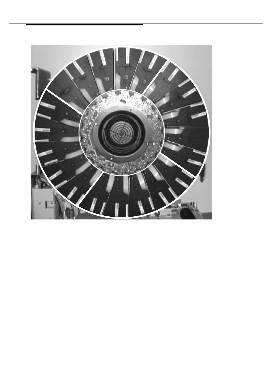
Figure 8-17. Linear Amplifier Module (LAM)
Series II Cell Site
Linear Amplifier
Unit (LAU)
The Linear Amplifier Unit (LAU) (see Figure 8-18) receives the Radio Frequency
(RF) output from the linearizer unit (LZR) and applies it to an Linear Amplifier
Module (LAM) where it is amplified and then processed out to the Antenna
Lucent Technologies — Proprietary
See notice on first page
8-54 401-660-100 Issue 11 August 2000
Series II Cell Site Equipment Descriptions
Interface Frame (AIF). The LAU also contains a cooling fan and a temperature
sensor (overheat sensor).
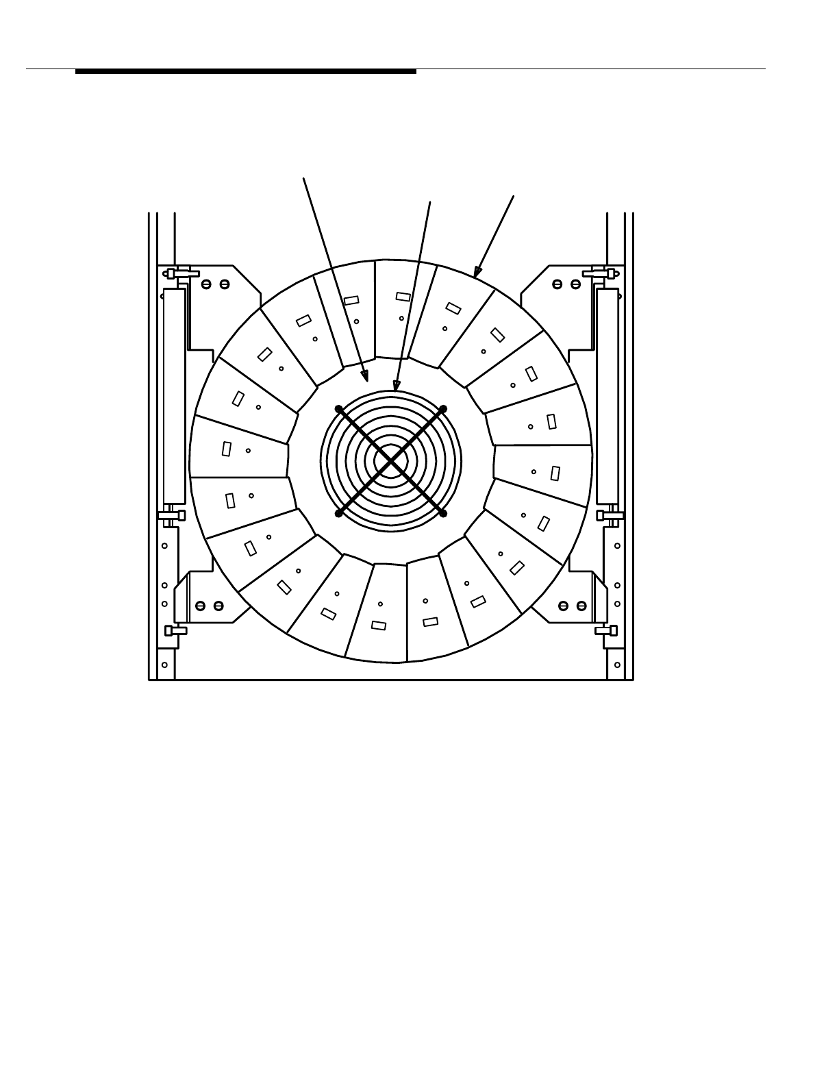
Figure 8-18. Linear Amplifier Unit ED-2R839-30
MODULE
ED-2R840-30
LINEAR AMPLIFIER
FAN
PRINTED WIRING
FRONT VIEW
BOARD AYM3
Lucent Technologies — Proprietary
See notice on first page
401-660-100 Issue 11 August 2000 8-55
Series II Cell Site Equipment Descriptions
Figure 8-19. Location of LAM Fuses, LEDs, and the 10/20 Switch (on C-Series
LACs)
Series II Cell Site,
20-LAM LAC
Versus 10-LAM
LAC
When Linear Amplifier Circuits (LACs) are shipped from the factory, they are
configured as full-power (20-LAM) LACs (see Figure 8-19). If they are to be
installed as low-power (10-LAM) LACs, an in-line SMA attenuator must be
installed in Series with a coaxial cable in the Linearizer (LZR) and, on C-Series
LACs, the 10/20 switch on the front of the circuit AYM board must be changed to
the 10 position. To change back to a 20-LAM LAC, the in-line attenuator must be
removed and the switch returned to the 20 position. A label (CONVERSION
RECORD) is provided on the front face of the Linearizer cabinet on C-Series
LACs and should be marked with the date of any 10/20 conversion. A suitable
label should also be placed on any A/B-Series LACs which are converted.
NOTE:
Any new C-Series LACs shipped from the factory as replacements will not
have attenuators. The attenuators may be obtained from Lucent
Technologies as a spare part, Comcode 406825794 or 406822064. Any
LAM
LEDs
10/20
SWITCH
LAM
FUSES

Lucent Technologies — Proprietary
See notice on first page
8-56 401-660-100 Issue 11 August 2000
Series II Cell Site Equipment Descriptions
new C-Series, half-power LACs ordered will have the attenuator shipped
loose as part of J41660CA-1, List 3 or J41660CA-2, List 4.
Series II Cell Site
Linearizer Unit
ED-2R841-30
The Linearizer unit (LZR) (see Figure 8-20, and Figure 8-23) is located in a shelf
below each Linear Amplifier Unit (LAU). The LZR contains circuits that function to
reduce intermodulation distortion. The LZR contains a power fault monitor board.
This board monitors faults and sends alarms back to the Radio Control Frame
(RCF).
The Linearizer Unit (LZR) receives the combined Radio Frequency (RF) input
from the Frame Interface Assembly (FIA) and functions to reduce the
intermodulation distortion prior to applying the RF input to the Linear Amplifier
Unit (LAU). The LZR also has circuits to monitor alarm conditions on the Linear
Amplifier (LAF).
Lucent Technologies — Proprietary
See notice on first page
401-660-100 Issue 11 August 2000 8-57
Series II Cell Site Equipment Descriptions
Figure 8-20. Linearizer (LZR) Unit ED-2R841-30
BOARD (PRE-DISTORTION
AYH1 PRINTED WIRING
J44
DELAY LINE
WP-92068, L2
(FACEPLATE REMOVED FOR CLARITY)
FAN
BASE
LINEARIZER
PART OF KIT,
LINEARIZER
PART OF KIT,
DIRECTIONAL COUPLER
AMPLIFIER (FCA))
(FINAL CORRECTION
AYH2 PRINTED WIRING BOARD
DRIVER (PDD))
846492015
846531754
BRACKET, FAN
846491843
846531754
CIRCULATOR
WP-92702, L1
KS-21603, L5
FRONT VIEW
J32
J48
FLOW
AIR
J42
FRONT VIEW
ADJUSTER 2 (GPA2))
PWB (GAIN PHASE
AYF2
105517155
PIN, DESIGNATION
KS-14174,L ( )
Lucent Technologies — Proprietary
See notice on first page
8-58 401-660-100 Issue 11 August 2000
Series II Cell Site Equipment Descriptions
Figure 8-21. Linearizer Unit ED-2R841-30
TOP VIEW
HY1
CP2
J49
J32
J41
J52
J4
J25
J35
P11
P15
J5
J44
J36
-10 -50
AYF1 PRINTED WIRING
BOARD (GAIN PHASE
ADJUSTER 1 (GPA1))
AYE1 PRINTED WIRING
BOARD (CONTROLLER/
ANALYZER BOARD (CAB))
AYE2 PRINTED WIRING
BOARD (RF POWER
SENSOR (RPS))
AYG1 PRINTED WIRING
BOARD (POWER FAULT
MONITOR (PFM))
Lucent Technologies — Proprietary
See notice on first page
401-660-100 Issue 11 August 2000 8-59
Series II Cell Site Equipment Descriptions
Figure 8-22. Linearizer Unit ED-2R841-30
J31
J51
J50
J46
J37
J38
J47
J45
BOTTOM VIEW
J3
J6
J2
J1
J9
J7
J8
J10
P14
REAR VIEW
P1
J33
P13
Lucent Technologies — Proprietary
See notice on first page
8-60 401-660-100 Issue 11 August 2000
Series II Cell Site Equipment Descriptions
Figure 8-23. Linearizer Faceplate with the Front Grille Removed
Please refer to Lucent Technologies Practice 401-660-125 for a full description of
the Modular Linear Amplifier Circuit (MLAC) J-41660CA-3.
INPUT DRIVE
ANTENNA
PRE-AMPLIFIER
LINEARIZER
INPUT DRIVE
FANS
FCA
STATUS
LINEARIZER
FAN
LINEAR
AMPLIFIER
UNIT
FAN
PRE
AMPLIFIER
STATUS
LINEARIZER
FAN
LINEAR
AMPLIFIER
UNIT
FAN
PRE
AMPLIFIER
PRE-AMPLIFIER
LINEARIZER
10A
24V
3A
24V
2A
24V
2A
24V
5A
24V
LINEAR
AMPLIFIER
UNIT
LINEAR
AMPLIFIER
UNIT

Lucent Technologies — Proprietary
See notice on first page
401-660-100 Issue 11 August 2000 8-61
Series II Cell Site Equipment Descriptions
Series II Cell Site Frame Interface
Assembly ED-2R838-30
The frame interface assembly contains the connectors used to interface the Linear
Amplifier Frame (LAF) with the power plant and Radio Channel Frames (RCFs).
Also, this assembly contains 20 capacitors used to filter the +24 volt supply.
The Frame Interface Assembly (FIA) (see Figure 8-24) contains a bank of filter
capacitors used to filter the DC voltage applied to the Linearizer unit (LZR) and
the Linear Amplifier Unit (LAU). In addition, the FIA combines the Radio
Frequency (RF) inputs from the Radio Channel Frames (RCFs) through a 3:1
power combiner and applies the combined RF output to an attenuator/
preamplifier. The output of this attenuator/preamplifier is adjusted as required and
applied to the LZR. Also, Linear Amplifier Frame (LAF) alarm status request and
alarms pass through the FIA.
Lucent Technologies — Proprietary
See notice on first page
8-62 401-660-100 Issue 11 August 2000
Series II Cell Site Equipment Descriptions
.
Figure 8-24. Frame Interface Assembly ED-2R838-30
(DOOR, HINGES, CABLE DUCT & BRACKET, CONNECTOR REMOVED)
TOP VIEW
C3
C4
C5
C13
C14
C15
C18
C19
C20
C8
C9
C10
LAC 6
LAC 2 LAC 3 LAC 5
LAC 1
LAC 4
LAC 0
EFERENCE ONLY
HOWN FOR
/O J41660CA-1
OUTLET
P3
LAC 6
LAC 2
PA1
P4
LAC 3
PD1
PA1PA1
LAC 5
LAC 1
P2
LAC 4
LAC 0
P1
INLET
AIR
PD1
(LAC 4)
(LAC 0)
(LAC 6)
(LAC 2)
AIR
PD1
(LAC 5)
(LAC 1)
PD1
PA1
(LAC 3)
Lucent Technologies — Proprietary
See notice on first page
401-660-100 Issue 11 August 2000 8-63
Series II Cell Site Equipment Descriptions
Figure 8-25. Frame Interface Assembly ED-2R838-30
REAR VIEW
LAC 3
P4
LAC 6
LAC 2
P3
LAC 4
LAC 0
P1
LAC 5
LAC 1
P2
TB1
C1
C20
C8
C9
C10
C19
C18
C5C15
C4C14
C7
C6 C11C16
C17 C2
C3C13
C12
ED2R83B-30
J2J1
BOTTOM VIEW (CABLE DUCT REMOVED)
Lucent Technologies — Proprietary
See notice on first page
8-64 401-660-100 Issue 11 August 2000
Series II Cell Site Equipment Descriptions
Series II Cell Site Antenna Interface
Frame (AIF), Overview
The major hardware units on the Antenna Interface Frame (AIF) are listed below
and are described functionally in the following paragraphs.
■Receive, Alarm, and Power Distribution Panel
■Reference Frequency Generator (RFG)
■Radio Test Unit (RTU) Switch
■Receiver Calibration Generator (RCG)
■Receive Filter Panel (RFP)
■Transmit Filter Panel.
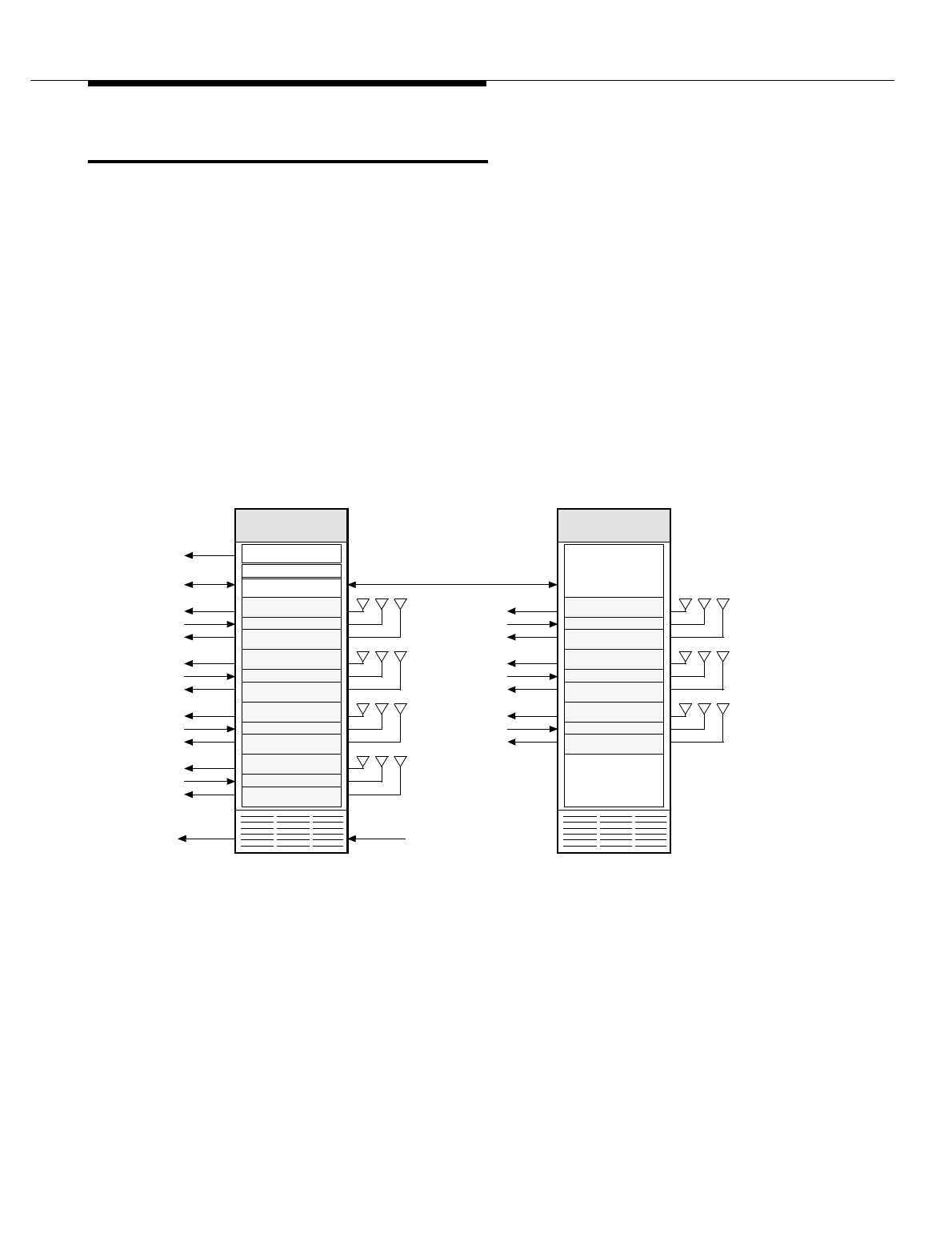
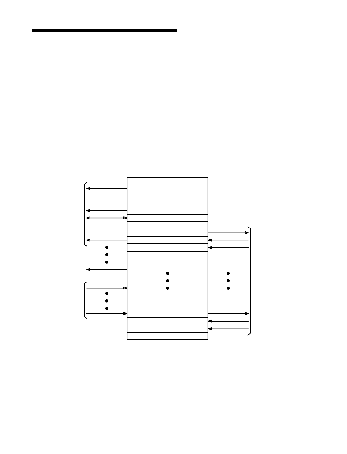
Figure 8-26. Antenna Interface Frame (AIF) Functional Diagram
The Antenna Interface Frame (AIF) has two configurations—a primary frame
(J41660E-2) and a growth frame (J41660F-2). The Antenna Interface Frame
(AIF) provides the interface and signal filtering circuitry required to complete the
REF FREQ GEN
RCVR CAL GEN
RTU Switch Panel
RCF
LAC 3
RCF
RCF
LAC 2
RCF
RCF
LAC 1
RCF
RCF
LAC 0
RCF
RCC
PRIMARY—AIF0
ALARMS
GROWTH—AIF1
RCF
15 MHz
RX 0 RX 1TX
RX 0 RX 1TX
RX 0 RX 1TX
RX 0 RX 1TX
RCF
LAC 6
RCF
RCF
LAC 5
RCF
RCF
LAC 4
RCF
RX 0 RX 1TX
RX 0 RX 1TX
RX 0 RX 1TX
FIF
ALARMS
ANT 0
ANT 1 ANT 5
ANT 3
ANT 2 ANT 6
ANT 4
RTU/
TRTU/
CRTU
Lucent Technologies — Proprietary
See notice on first page
401-660-100 Issue 11 August 2000 8-65
Series II Cell Site Equipment Descriptions
Cell Site Receive (RX) and Transmit (TX) RF paths from the RX and TX antennas
to the LAFs and Radio Channel Unit (RCUs) inside the RCFs. This is
accomplished through the TX and RX filter panels (TFPs and RFPs) in the AIF.
In addition to the Radio Frequency (RF) filtering and interface circuitry, the AIF
contains the test circuitry required for radio diagnostics. A test switch matrix is
used to establish the required test paths. A Receiver Calibration Generator (RCG)
is used to set a known level for RX path loss calibration. The AIF also contains a
highly accurate Cell Site Reference Frequency Generator.
The major assemblies making up each configuration are listed and described
below. Note that a duplexer filter panel is available to replace the separate receive
and transmit filter panels. The duplexer filter panel has one configuration for the
“A” band and another for the “B” band.
Figure 8-27. Antenna Interface Frame (AIF) Functional Architecture
RECEIVE FILTER PANEL
TRANSMIT FILTER PANEL
ANTENNAS
TO
CABLES
FEEDER
COAX
FRAME(S)
AMPLIFIER
LINEAR
TO
TRANSMIT RF
TO
RECEIVE FILTER PANEL
RECEIVE FILTER PANEL
RECEIVE FILTER PANEL
TRANSMIT FILTER PANEL
CALIBRATION GENERATOR
TEST SWITCH MATRIX
REF FREQ GENERATOR
POWER/ALARM
RECEIVE RF
RF TEST
REFERENCE
ALARMS
SET
FRAME
CHANNEL
RADIO
Lucent Technologies — Proprietary
See notice on first page
8-66 401-660-100 Issue 11 August 2000
Series II Cell Site Equipment Descriptions
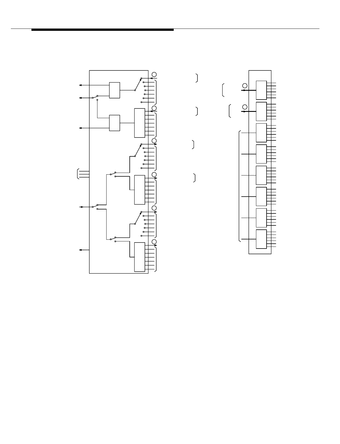
Figure 8-28. Antenna Interface Frame (AIF) Functional Diagram
SH 1
FROM
FROM
RCF0
FUTURE
CONTROL
ANTENNA
MONITOR
RCF0
TO
MONITOR
5
4
3
RTU TX J1
FROM OTHER
FROM OTHER
7:11:2
1:2
XMTR
POWER AND
TX-ANT
SWITCH PANEL (RSP)
RTU
J4
J2
J3
RTU RX
TRANSMIT
TO OTHER DIV0
P1
1:7
1:7
8
7
6
P2
DIV1
DIV0
TO
TO OTHER DIV1
TO OTHER DIV1
RFP’s (-50 dB PORT)
RX-ANT
RCVR
RX-ANT
RCVR
APPLICATIONS
AIF0
DFP’s
OR
RFP’s
OTHER
FROM
1:6
1:6
1:6
1:6
RFP’s (-40 dB PORT)
TO R1FP0 (-40 dB PORT), SH 3
TO R1FP0 (-50 dB PORT), SH 3
SH 3
RFP’s (-40 dB PORT)
RFP’s (-50 dB PORT)
OR DFP0 (PD2-J3)
TO R0FP0 (-40 dB PORT)
OR DFP’S (PD2-J2)
FROM
SH 3
FROM
SH 3
FROM
TO R0FP0 (-50 dB PORT)
FROM
R1FP0
AIF0
FROM 10
9
RAP
1:6
1:6
1:6
DFP0
R0FP0 OR
FROM AIF0
SH 3
TO
SH 3
OR DFP0 (PD1-J3)
OR DFP’s (PD2-J2)
OR DFP’s (PD1-J2)
TFP’s (-40 dB PORT)
TFP’s (-50 dB PORT)
TO OTHER DIV0
OR DFP0 (PD2-J2)
OR DFP0 (PD1-J2)
FROM TFP0 (-40 dB PORT)
FROM TFP0 (-50 dB PORT) SH 3
1:6
OR DFP’s (PD1-J3)
RTU-S RAP
Lucent Technologies — Proprietary
See notice on first page
401-660-100 Issue 11 August 2000 8-67
Series II Cell Site Equipment Descriptions
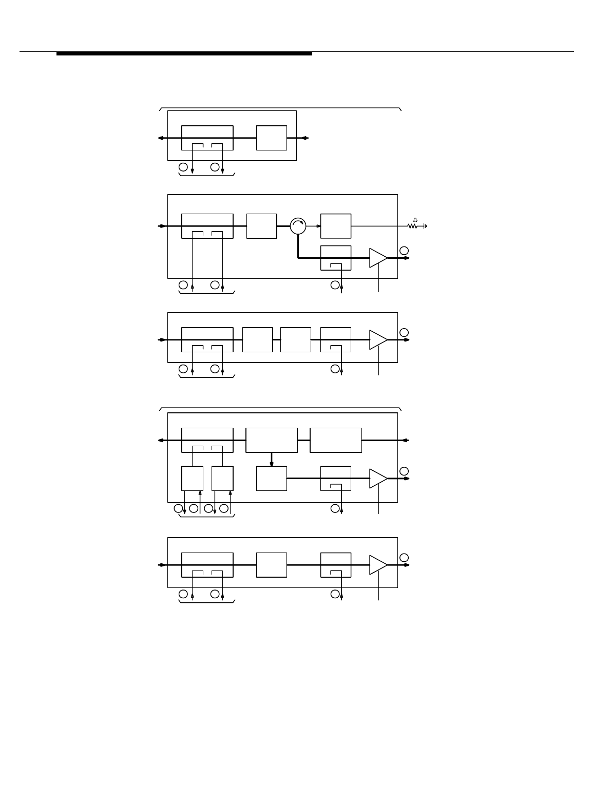
Figure 8-29. Antenna Interface Frame (AIF) Functional Diagram
1
FROM RCG
2
78
(SH 2)
+24V
J3
(SH 1)
-50 dB-40 dB
10
FROM
RECEIVE
CP1
(SH 2)
TO RAP
CP2
BPF
FL1
R1FP0
RECEIVE FILTER PANEL
J4
ANTENNA
FROM RCG +24V
536
(SH 1)
(SH 2)
TO/FROM RSP
4
9
J3
PD1
J3J2
1:2
J3
(SH 2)
TO RAP
CP2
BPF
FL1
J2
1:2
PD2
-50 dB-40 dB
ANTENNA LAC0
FROM
BPF
FL3
DUPLEXER
TRANSMIT/RECEIVE
CP3
J4
TO COMBINED
DFP0
TRANSMIT
TO FROM
(NON-DUPLEXER)
CP3
TFP0
TRANSMIT FILTER PANEL 0
J4
ANTENNA
4
FROM
FROM RSP
3
CP1
LINEAR AMPLIFIER
FL3
-40 dB
TO RSP
(SH 2)
CIRCUIT 0
BPF (LAC0)
-50 dB
(SH 1)
(SH 2)
DUPLEXER FILTER PANEL
(DUPLEXER)
TYPICAL FILTER PANEL SET
+24V
6
RECEIVE J4
ANTENNA
FROM
RECEIVE
8
J4
ANTENNA
FROM RSP
5
7
CP1
-40 dB
FROM RCG
J3
2
-50 dB
(SH 2)
-40 dB
FROM RSP
BPF
FL1
BPF
-50 dB
FL1
HY1
R0FP0 (A BAND)
RECEIVE FILTER PANEL, DIV0
(SH 2)
(SH 2)
TO RAP
+24V
10
FROM RCG
(SH 1)
R1FP0 (B BAND)
NOTCH
FL2 CP2
RECEIVE FILTER PANEL, DIV1
FL2
NOTCH
J3
1
CP2
50
TO RAP
9
Lucent Technologies — Proprietary
See notice on first page
8-68 401-660-100 Issue 11 August 2000
Series II Cell Site Equipment Descriptions
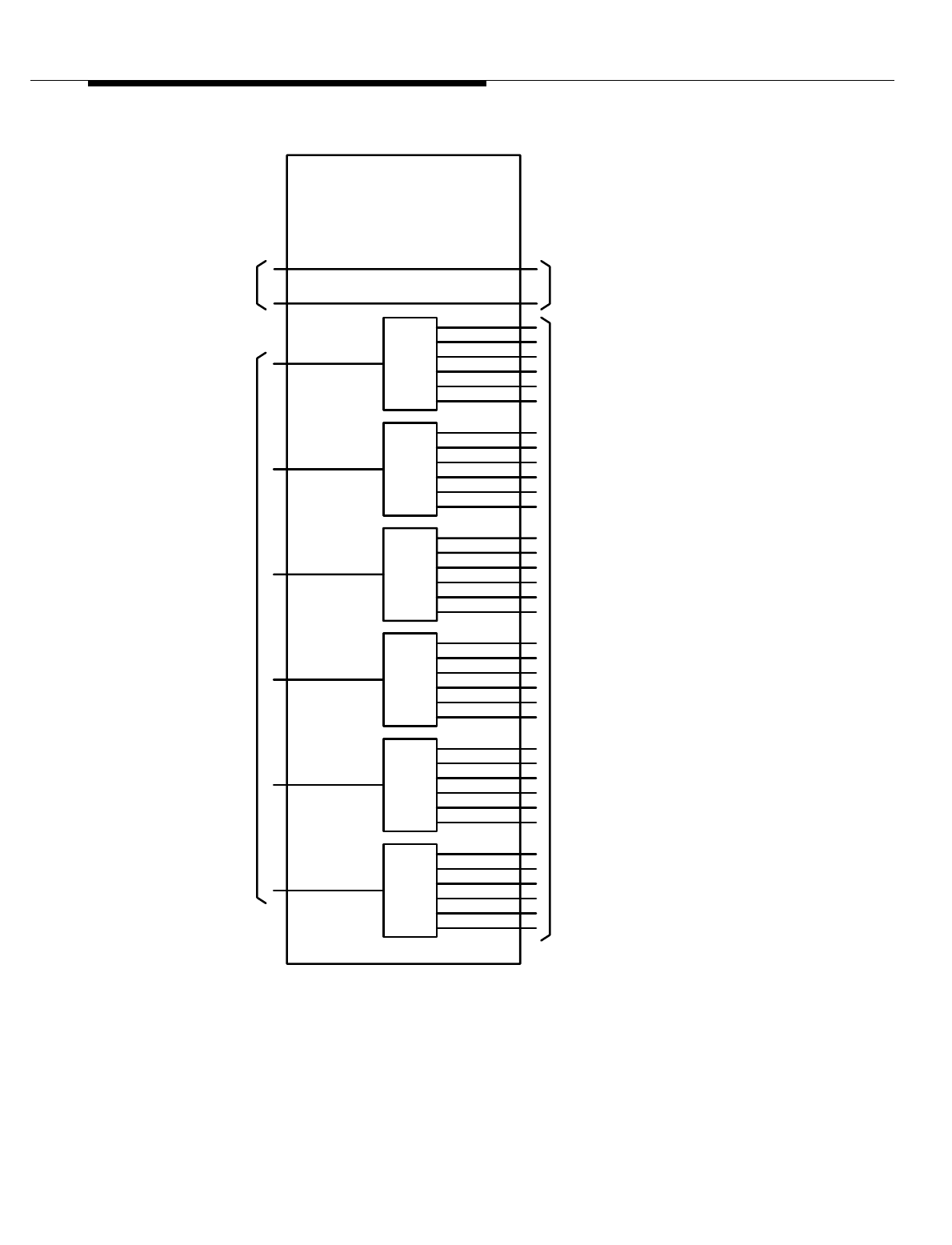
Figure 8-30. Antenna Interface Growth Frame (AIF) Functional Diagram
RCF(s)
DIV1 PREAMP POWER
AIF1
DFP’s
OR
RFP’s
FROM
1:6
1:6
1:6
1:6
OUTPUTS
AIF1
(RP)
DISTRIBUTION
RECEIVE AND POWER
AIF1 PREAMPS
TO
+24V FEEDERS
DIV0 PREAMP POWER
IF0
ROM
EEDERS
24V
TO
1:6
1:6

Lucent Technologies — Proprietary
See notice on first page
401-660-100 Issue 11 August 2000 8-69
Series II Cell Site Equipment Descriptions
Series II Cell Site
Reference
Frequency
Generator (RFG)
Shelf
The Reference Frequency Generator (RFG) provides a 15-MHz precision
reference frequency at a level of +12 dBm ±2 dB. The 15-MHz signal is used as a
reference frequency by the Radio Channel Units (RCUs) and the Radio Test Unit
(RTU) to produce the desired output frequency. The oscillator circuit is monitored
for and indicates when a fault has occurred. When the RFG shelf supports two
oscillators, only one oscillator is on line at a time as indicated by Light Emitting
Diodes (LEDs).
There are three options available for the RFG shelf, as follows:
1. RFG shelf with one (1) Rubidium oscillator.
2. RFG shelf with two (2) Rubidium oscillators.
3. RFG shelf with one (1) Rubidium oscillator and one (1) crystal oscillator.
Series II Cell Site Receiver Calibration Generator ED-2R845-30
This unit generates the Radio Frequency (RF) test signals used in calibrating the
RF path loss within the Cell Site.
The Receiver Calibration Generator (RCG) provides a stable unmodulated
calibration signal on Mobile Transmit channel 990. The RCG has a total of 16
Radio Frequency (RF) ports (only 14 are used). These ports are coupled to the
inputs of the preamplifiers in the receive paths inside the AIF through 20-dB
directional couplers. The calibration signal is used by each Radio Channel Unit
(RCU to determine a correction factor required for its Received Signal Strength
Indicator (RSSI) output. The correction factor is used to compensate for non
frequency dependent losses in each RCU receive path.
The stability of the RCG output frequency is the same as that of the 15-MHz
reference frequency. The RCG output frequency is factory preset to channel
990—824.01 MHz. The nominal output power level of each of the 16 RCG ports is
-58 dBm ±1.5 dB.
There are four translations entries which affect Receiver Calibration.
■Frequency (Found in the Cell Form)
■Tolerance (Also found in the Cell Form)
■Receive Signal Strength Calibration Diversity 0 (Referred to as the
Expected Value, found in the CEQFACE form)
■Receive Signal Strength Diversity 1 (Referred to as the Expected Value,
also found in the CEQFACE form).
The RCUs must be reset before these parameters will have an effect. The
Receive Signal Strength Calibration parameters for diversity 0 and 1 apply to each
face. Changing either of these parameters will only affect the RCUs on that face.

Lucent Technologies — Proprietary
See notice on first page
8-70 401-660-100 Issue 11 August 2000
Series II Cell Site Equipment Descriptions
During an RCU restore sequence, the data decoder tunes to the calibration
channel (990) and makes signal strength measurements for each antenna
diversity. As a result of these measurements, one of the following three things
happens:
■If the measurement falls within the tolerance value but is not exactly the
same as the expected value, the decoder records the difference between
the expected value and the actual measurement. Subsequent
measurements made by that radio are adjusted by this value.
■If any of the measurements fall outside of tolerance, no corrections are
made to the measured signal strengths. Also, a Receiver Calibration HEH
Error message is printed out on the receive-only printer (ROP).
■If the measured value is the same as the expected value, no adjustments
are made.
Receiver calibration errors can be the result of incorrect translations, defective RF
cabling, faulty RCUs, defective preamps, or basically any problem found between
the RCG and the RCUs.
There are two AIF models—AIF0 (primary) and AIF1 (growth). AIF0 contains a
Receive, Alarm, and Power Distribution Panel (RAP), an RFG, an RCG, and a
Radio Test Unit Switch Panel (RSP). AIF0 can be equipped with one to four sets of
filter panels (a single set consists of one TX and two RX filter panels unless it is
duplexed).
AIF1 Frame 0
AIF1 serves as an auxiliary frame to accommodate additional filter panels. It
contains a Receive and Power (RP) Distribution Panel and can be equipped with
one to three additional filter panel sets.
Integrated Duplexer Filter Panels (DFPs) are optional. When equipped, a DFP
assembly can be used to combine a TX filter panel with an RX filter panel and
share one combined RX/TX antenna port, thus reducing the required number of
antennas from three to two per antenna face. Unless otherwise specified, a DFP
combines the RX DIV0 path with the TX path.
AIF0 combined with AIF1 accommodates up to seven antenna faces, typically
consisting of seven TX paths and 14 RX paths. Each antenna face requires an RX
filter for the diversity 0 (DIV0) RX path, a TX filter for the TX path, and an RX filter
for the diversity 1 (DIV1) RX path.
There are some interframe connections between AIF0 and AIF1 to provide the
following circuit functions. The RSP in AIF0 switches test signals from the RTU
(located in the P-RCF) to and from various RX and TX paths of both AIF0 and
AIF1 for system diagnostics. The RAP panel in AIF0 connects the +24 volt DC
power supplies to all of the preamplifiers inside the Receiver Filter Panels (RFPs)

Lucent Technologies — Proprietary
See notice on first page
401-660-100 Issue 11 August 2000 8-71
Series II Cell Site Equipment Descriptions
or DFP(s) of both AIF0 and AIF1. The RCG in AIF0 provides a leveled signal to
calibrate all of the RX paths from the AIF equipment all the way to the inputs of the
RCUs. There are RF connections from AIF0 to the RCF(s), the LAF(s), the RX
antennas and the TX antennas.
Lucent Technologies — Proprietary
See notice on first page
8-72 401-660-100 Issue 11 August 2000
Series II Cell Site Equipment Descriptions
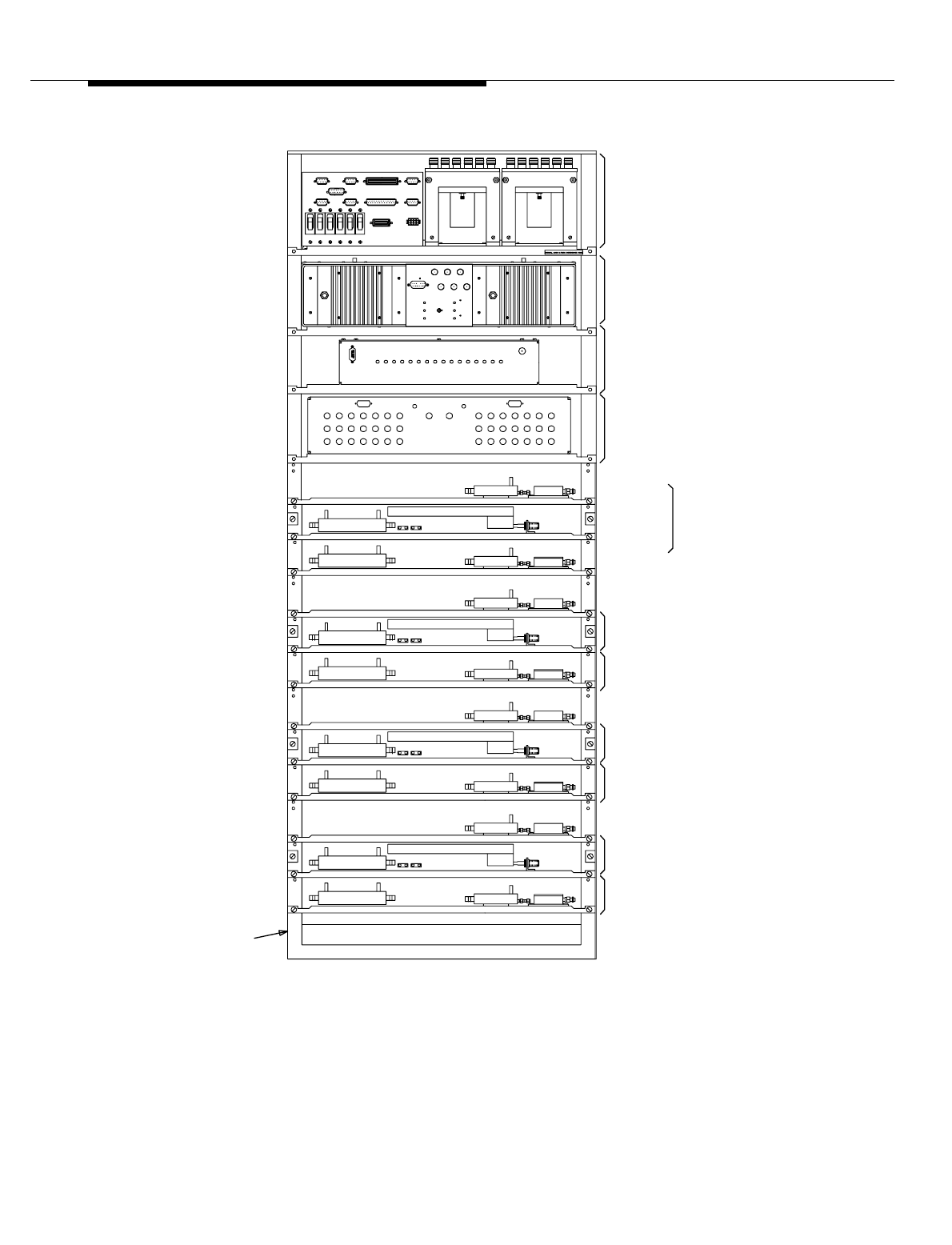
Figure 8-31. Primary Antenna Interface Frame (AIF) J41660E-2
DUPLEXER FILTER
PANEL
RECEIVE FILTER
PANEL
PANEL
RECEIVE FILTER
PANEL
DUPLEXER FILTER
PANEL
RECEIVE FILTER
PANEL
ABINET
RECEIVE
SECTION
TRANSMIT
SECTION
RECEIVE FILTER PANEL
RADIO TEST UNIT
RECEIVE, ALARM & POWER
DISTRIBUTION PANEL
REFERENCE FREQUENCY
RECEIVER CALIBRATION
DUPLEXER
FILTER
PANEL
D-2R820-30
DUPLEXER FILTER
GENERATOR
GENERATOR
SWITCH
PRIMARY FRAME - WITH DUPLEXER FILTER PANEL
Lucent Technologies — Proprietary
See notice on first page
401-660-100 Issue 11 August 2000 8-73
Series II Cell Site Equipment Descriptions
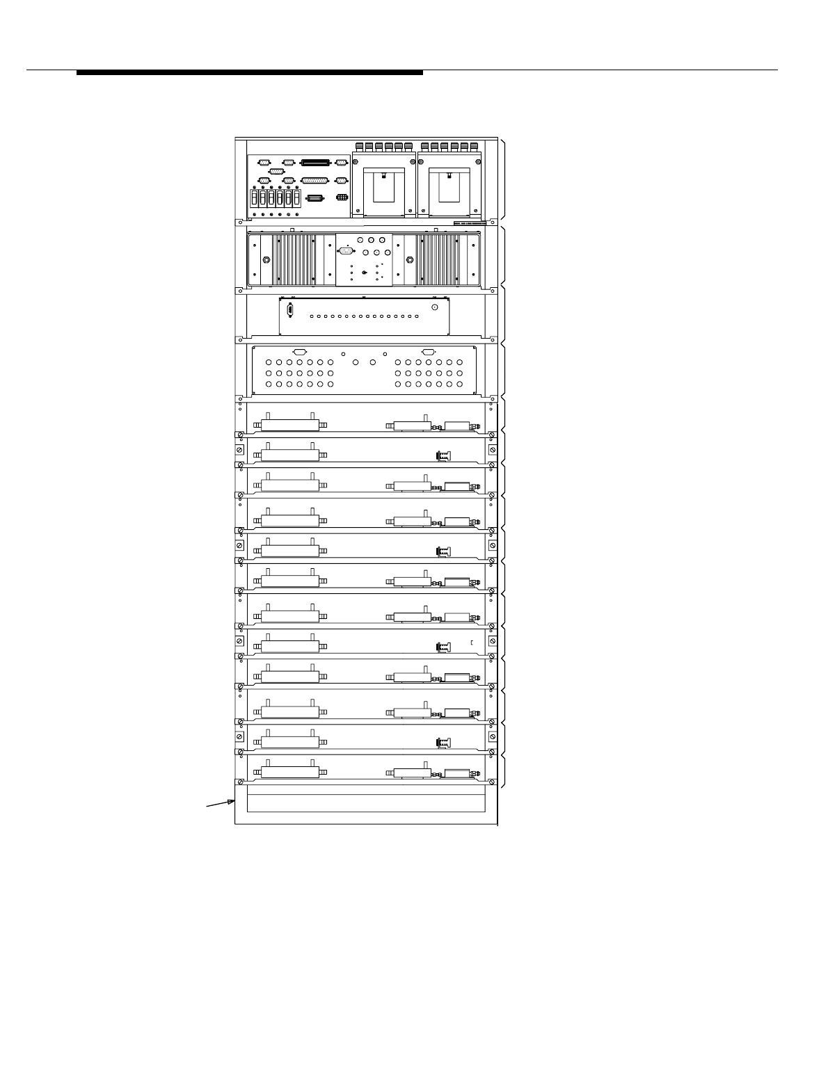
Figure 8-32. Primary Antenna Interface Frame J41660E-2
PANEL
PANEL
RECEIVE FILTER
TRANSMIT FILTER
PANEL
RECEIVE FILTER
PANEL
RECEIVE FILTER
PANEL
PANEL
RECEIVE FILTER
TRANSMIT FILTER
PANEL
D-2R820-30
ABINET
PANEL
RECEIVE FILTER
TRANSMIT FILTER
PANEL
RECEIVE FILTER
RADIO TEST UNIT
RECEIVE FILTER
RECEIVE FILTER
TRANSMIT FILTER
REFERENCE FREQUENCY
RECEIVER CALIBRATION
RECEIVE, ALARM & POWER
DISTRIBUTION PANEL
GENERATOR
GENERATOR
SWITCH
PANEL
PANEL
PANEL
PRIMARY FRAME - WITHOUT DUPLEXER FILTER PANEL
Lucent Technologies — Proprietary
See notice on first page
8-74 401-660-100 Issue 11 August 2000
Series II Cell Site Equipment Descriptions
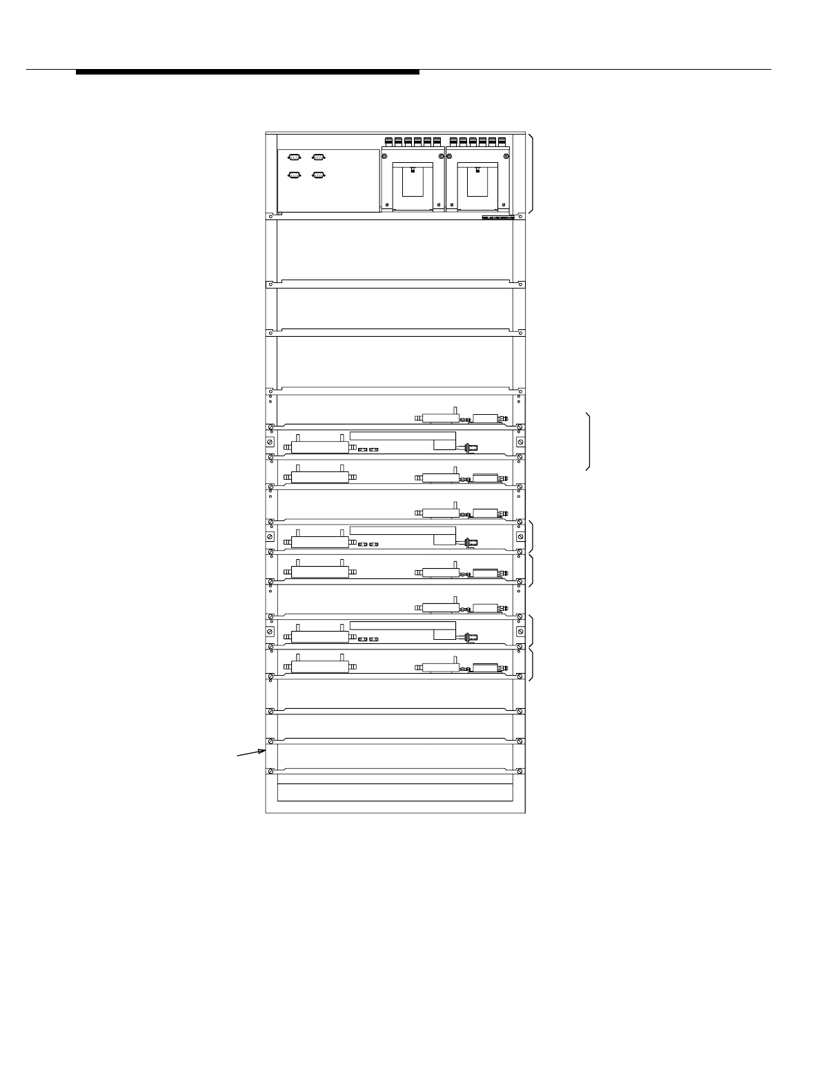
Figure 8-33. Growth Antenna Interface Frame J41660F -2
DUPLEXER FILTER
PANEL
RECEIVE FILTER
PANEL
DUPLEXER FILTER
PANEL
RECEIVE FILTER
D-2R820-30
ABINET
PANEL
RECEIVE
SECTION
TRANSMIT
SECTION
RECEIVE FILTER PANEL
DISTRIBUTION PANEL
DUPLEXER
FILTER
PANEL
POWER AND
SECONDARY FRAME-WITH DUPLEXER FILTER PANEL
Lucent Technologies — Proprietary
See notice on first page
401-660-100 Issue 11 August 2000 8-75
Series II Cell Site Equipment Descriptions
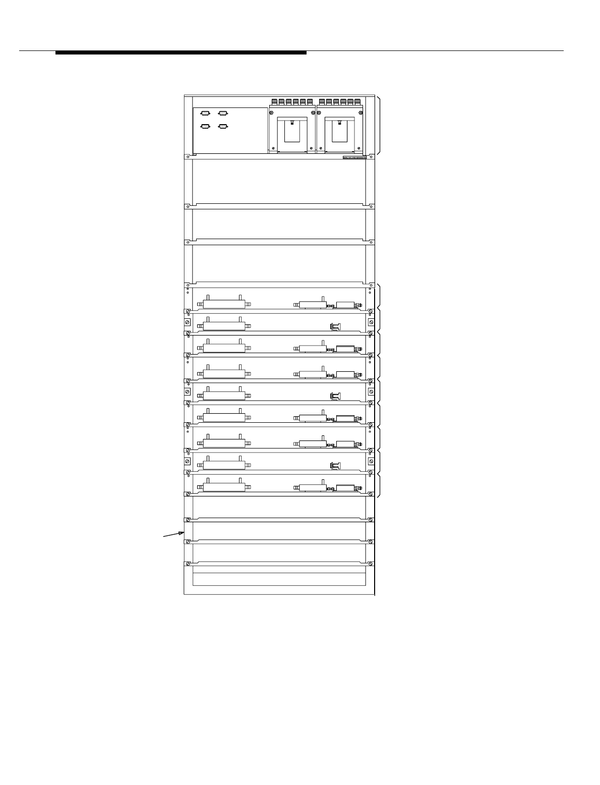
Figure 8-34. Growth Antenna Interface Frame J41660F-2
PANEL
PANEL
RECEIVE FILTER
TRANSMIT FILTER
PANEL
RECEIVE FILTER
PANEL
PANEL
RECEIVE FILTER
TRANSMIT FILTER
PANEL
RECEIVE FILTER
ED-2R820-30
CABINET
RECEIVE FILTER
TRANSMIT FILTER
RECEIVE FILTER
DISTRIBUTION PANEL
RECEIVE AND POWER
PANEL
PANEL
PANEL
SECONDARY FRAME-WITHOUT DUPLEXER FILTER PANEL

Lucent Technologies — Proprietary
See notice on first page
8-76 401-660-100 Issue 11 August 2000
Series II Cell Site Equipment Descriptions
Series II Cell Site
Radio Switch
Panel
Series II Cell Site Radio Test Unit (RTU) Switch Panel
This switch panel establishes the functional Radio Frequency (RF) test path used
by the Radio Test Unit (RTU) during diagnostic testing. These paths include the
following:
■Receiver-Forward Signal Injection
■Receiver-Reflected Signal Injection
■Transmit-Forward Signal Measurement
■Transmit-Reflected Signal Measurement.
The test paths are made through directional couplers containing forward and
reflected ports. Under software control, the RTU switch establishes the required
paths to test all major functional operations.
The Radio Switch Panel (RSP) provides the RTU (located in RCF0) access to the
Cell Site Rx and Tx (Receive and Transmit) paths through a test matrix Radio
Frequency (RF) distribution network. The RTU is coupled to the incident and
reflected path of every antenna used by the Cell Site through the RSP. RF test
signals to and from the RTU test receiver and the transmitter are connected to the
RSP. The RSP receives logic control signals from the RTU to switch the RF test
signals from the RTU to the Rx and Tx paths under test.
The RTU is used primarily to verify the Rx and Tx paths to and from the transmit
and receive antennas of the Cell Site. The RTU contains a test receiver and test
generator which serve to simulate a subscriber unit. The test receiver and the test
generator can be tuned to any channel. Tuning is accomplished with commands
sent over the TDM bus to an Rx/Tx frequency synthesizer within the RTU. The
RTU controls the RF switches located in the RSP. The TDM bus is always installed
"red stripe up."
During Rx testing on a Cell Site Radio Channel Unit (RCU), the test generator
within the RTU is tuned to the channel under test, and the output of the test
generator is applied to the appropriate Cell Site receiving antenna. Control is
applied to the RSP in AIF0 to select Omni Rx or one face of the directional
antenna. RCU transmitter testing is accomplished by connecting the test receiver
to the appropriate Tx path and tuning the RTU to the channel under test.
Series II Cell Site
Receive, Alarm,
and Power
Distribution Panel
ED 2R851-30
This panel provides an interface between the primary Antenna Interface Frame,
AIF0, and other Cell Site equipment for distributing the receive signals, the alarm
and control signals, and the +24-volt DC power. The +24-volt DC for the growth
AIF1 is supplied from this panel.
The Receive, Alarm, and Power (RAP) distribution panel contains the circuit
breakers that feed +24 volts to units on the primary Antenna Interface Frame (AIF)
and to the growth frame. This panel also contains power dividers used to distribute

Lucent Technologies — Proprietary
See notice on first page
401-660-100 Issue 11 August 2000 8-77
Series II Cell Site Equipment Descriptions
received Radio Frequency (RF) to the Radio Channel Frame (RCF) and alarm tie-
points for customer alarms. These alarms are fed back to the Alarm/FITS (Factory
Installation Test Set) board located on the P-RCF.
The +24 volt DC power from the power plant is applied as FDR0 through CB1 to
the RFG, through CB4 to the Receiver Calibration Generator (RCG), and through
CB5 to all of the preamplifiers inside the DIV0 Rx filter panels of both AIF0 and
AIF1. FDR1 is applied through CB2 to the RFG, through CB3 to the RSP, and
through CB6 to the DIV1 Rx filter panels in both AIF0 and AIF1.
The RAP panel provides user alarm connections and alarm signals from the AIFs
to the RCF0 alarm circuits. It also provides interface connections between the
RTU (inside RCF0) and the RSP (inside AIF0). The antenna select output of the
RTU sends logic signals to command the RSP to switch the Radio Frequency
(RF) test signals from the RTU to various Rx and Tx (Receive and Transmit)
antenna paths under test. The antenna message acknowledge output of the RSP
acknowledges the RTU upon successful execution of its commands.
Series II Cell Site
Receive and Power
Distribution Panel
ED-2R853-31
This panel is located in the growth Antenna Interface Frame, AIF1, and provides
an interface between AIF1 and other Cell Site equipment for distributing the
receive signals and the +24-volt DC received from AIF0.
The outputs of the preamplifiers in the RFPs or DFPs are connected to the
respective 1:6 power dividers mounted inside the RAP. The amplified Rx signals
are distributed to the RCF(s). All of the unused ports on the 1:6 dividers must be
terminated into a 50-ohm resistive load.
The Receive and Power (RP) distribution panel distributes the Rx signals and +24
volt DC within AIF1. The outputs of the preamplifiers in the RFPs or DFP(s) are
connected to the 1:6 power dividers mounted inside the RP panel. The amplified
Rx signals are distributed to the RCF(s) from these power dividers.
Series II Cell Site
Duplexer Filter
Panel
ED-2R848-31
This filter panel is a combination receive and transmit filter panel with a single Rx/
Tx (Receive/Transmit) antenna port. Two configurations of this filter panel are
used—one for “A” band and one for “B” band. The group number designates the A
or B configuration.
One duplexer filter panel is required for each antenna face and one receive filter
panel is required for diversity.
The Duplexer Filter Panel (DFP) is a combined receive and transmit filter panel.
Functionally, the receive and transmit circuits are the same as the separate
receive and transmit filter panels, except that it provides a combined Rx/TS
(Receive/Transmit) antenna port. This allows the Cell Site to use one less
antenna. A separate list number is used to designate use with bands A and B.

Lucent Technologies — Proprietary
See notice on first page
8-78 401-660-100 Issue 11 August 2000
Series II Cell Site Equipment Descriptions
The Duplexer Filter Panel (DFP) combines a Tx filter panel with an Rx filter panel
and has a single Rx/Tx (Receive/Transmit) antenna port. A duplexing technique is
applied, enabling the system to use a combined Rx/Tx antenna configuration that
reduces the required number of antennas in each antenna face from three to two.
The duplexer steers the Rx signals from the combined Tx/Rx antenna to the input
of the BPF in the Rx path and directs the Tx signals from the output of the Tx filter
to the Tx/Rx combined antenna port. Unless otherwise specified, the duplexer is
normally used to combine the DIV0 Rx path with the Tx path.
The connections to the DFP are similar to those of the TFP and RFP, except there
is only one antenna port for the combined Tx/Rx antenna function. There is only
one dual-port directional coupler (-50 dB and -40 dB) required in the DFP. Two 2:1
combiners are used to provide connections to the RTU for radio test diagnostics.
The calibration signal from the Receiver Calibration Generator (RCG) is coupled
into the Rx path through a 20-dB directional coupler similar to that of the RFP.
Series II Cell Site
Receive Filter
Panel
ED-2R846-31
This filter panel contains a bandpass and a notch filter, a low-noise receive
preamplifier and two couplers used to inject forward and reflected Radio
Frequency (RF) test signals. These test signals are used to test the receive path
for the Radio Channel Units (RCUs). One filter panel is required for each receive
path inside the Antenna Interface Frame (AIF) unless a Duplex Filter Panel is
used.
The Receive Filter Panel (RFP) receives the Radio Frequency (RF) from the
receive antennas. The RF is first passed through a coupler where test signals may
be injected (forward and reflected). The RF is then passed through a bandpass
filter and a notch filter. A second coupler, after the filters, provides an injection
point for the Radio Channel Unit (RCU) calibration frequency. The receive RF is
then applied through a preamplifier to power dividers for distribution into the RCF.
The RFP works on both A and B bands.
One Receive Filter Panel (RFP) is required for each receive path inside the AIF
unless a Duplexer Filter Panel is used. Typically, each antenna face has two Rx
(Receive) paths for diversity 0 and diversity 1. The RFP contains a dual-port (-40
dB and -50 dB) directional coupler, a Band Pass Filter (BPF), a notch filter, a 20-
dB directional coupler, and a 44-dB preamplifier.
The received Radio Frequency (RF) signal from the Rx antenna is sent through
the dual-port directional coupler to the input of the BPF. The -40 dB and -50 dB
coupling ports of this coupler provide the RTU access to the Rx path of the AIF for
test purposes. The RTU sends and receives test signals through the RSP to these
ports in order to test the Rx path for each Radio Channel Unit (RCU) installed in
the RCF(s). Received RF signals from the Rx antenna are filtered and amplified
by the RFP before entering the RCU. The BPF (which is different for “A” and “B”
band customers) provides the required Rx path filtering characteristics. The
output of the BPF is followed by a notch filter.

Lucent Technologies — Proprietary
See notice on first page
401-660-100 Issue 11 August 2000 8-79
Series II Cell Site Equipment Descriptions
The calibration signal from the Receiver Calibration Generator (RCG) is coupled
into the Rx path through the 20-dB directional coupler at the output of the receive
filters. The calibration signal provides a means to determine a correction factor for
offsetting the difference in the loss tolerances in the different Rx paths of the
system.
The receive and calibration signals are amplified by the preamplifier inside the
RFP and sent to the RAP in AIF0 or the RP in AIF1.
A typical AIF0 with four antenna faces has a total of eight RFPs and eight 1:6
power dividers at the RAP, namely Face0 Rx0, Face0 Rx1, Face1 Rx0, Face1
Rx1, Face2 Rx0, Face2 Rx1, Face3 Rx0, and Face3 Rx1. A typical AIF1 with three
antenna faces has a total of six RFPs and six 1:6 power dividers at the RP, namely
Face4 Rx0, Face4 Rx1, Face5 Rx0, Face5 Rx1, Face6 Rx0, and Face6 Rx1. Each
RCF has at least one Rx path connection to one of the six ports of each 1:6
divider. This arrangement enables each RCF to have total access to all of the Rx
paths in AIF0 and AIF1. A maximum of six RCFs can be connected to each Rx
path to the 1:6 power dividers.
Series II Cell Site
Transmit Filter
Panel ED-2R847-31
This filter panel contains a transmit filter and a coupler for picking off a portion of
the forward and reflected power. These signals are used during Radio Frequency
(RF) diagnostic test.
The Transmit Filter Panel (TFP) receives transmitted Radio Frequency (RF) from
the LAF and passes it through a transmit filter assembly. The transmitted RF is
then fed through a coupler to the transmit antenna. The coupler provides ports for
picking off a portion of the forward and reflected RF.
One Transmit Filter Panel (TFP) is required for each antenna face. The TFP
contains a dual-port (-40 dB and -50 dB) directional coupler and a band pass
transmit filter. Tx (Transmit) signals from the Radio Channel Unit (RCU) are
amplified by the LAF before reaching the AIF. The Tx signals from the LAF are
filtered by the Tx filter inside the TFP before being transmitted out by the Tx
antenna. The filtered Tx signal is then sent through the dual-port coupler before
going to the Tx antenna. The -40 dB and -50 dB coupling ports of this coupler
provide the RTU access to the Tx path of the system for test purposes. The RTU
receives test signals through the RSP to these ports in order to test the Tx path for
each RCU installed in the RCF(s). The Tx filter separates out the unwanted
signals before transmitting to the Tx antenna.

Lucent Technologies — Proprietary
See notice on first page
8-80 401-660-100 Issue 11 August 2000
Series II Cell Site Equipment Descriptions
Table 8-14. Antenna Interface Frame (AIF) Hardware
Item Max
Qty Code Eqpt
Loc
Antenna Interface Frame 0 1 J41660E-2
Receive, Alarm, and Power Distribution Panel 1 ED-2R851-30 23
Circuit Breakers (CB1, CB2, CB3, CB4) 3A 4 406026401
Circuit Breakers (CB5, CB6) 2.5A 2 406085092
Terminal Strip (TB5, TB6) 2 406131862
Splitter Mounting Kit 2 846441368
Power Divider (1:6) 4
(per kit) KS21604,L12
RFG shelf with one (1) Rubidium oscillator 407575638 22
RFG shelf with two (2) Rubidium oscillators 407575653
Provides an RFG shelf with one (1) Rubidium
oscillator and one (1) crystal oscillator 407575646
Receiver Calibration Generator 1 ED-2R845-30 21
Power Divider 1 WP92070,L2
Signal Generator Circuit Pack 1 ARL3
Attenuator (AT1, AT3) 2 402910467
Attenuator (AT2) 1 402910442
Termination 2 461-1 (meca)
RTU Switch Panel 1 ED-2R850-30 20
TCI Circuit Pack 1 BBC1
RCV Circuit Packs 2 BBC2
Receive Filter Panel (“A” Band) ED-2R846-31
Coupler (CP1) 40/50 dB 1 KS21603,L8
Coupler (CP2) 20 dB 1 KS21603,L7
Bandpass Receive Filter (FL1) 1 ED-2R815-30
Notch Receive Filter (FL2) 1 ED-2R816-30
Item Max
Qty Code Eqpt
Loc
Circulator (HY1) 1 WP92072,L2
Preamp (PA1) 1 KS21583,L3
Adapter 1 406083055
Termination 1 401-1 (meca)

Lucent Technologies — Proprietary
See notice on first page
401-660-100 Issue 11 August 2000 8-81
Series II Cell Site Equipment Descriptions
Receive Filter Panel (“B” Band) ED-2R846-31
Coupler (CP1) 40/50 dB 1 KS21603,L8
Coupler (CP2) 20 dB 1 KS21603,L7
Bandpass Receive Filter (FL1) 1 ED-2R810-30
Notch Receive Filter (FL2) 1 WP92064,L1
Preamp (PA1) 1 KS21583,L3
Adapter 1 406083055
Transmit Filter Panel (“A” Band; Installer
Mounted) ED-2R847-31
Transmit Filter Panel (“B” Band; Installer
Mounted) ED-2R847-31
Coupler (CP3) 1 KS21603,L8
Bandpass Filter (“A” Band) 1 ED-2R860-30
Bandpass Filter (“B” Band) 1 ED-2R860-30
Duplex Filter Panel (“A” Band) ED-2R848-30
Coupler (CP2) 1 KS21603,L7
Coupler (CP3) 40/50 dB 1 KS21603,L8
Power Divider/Combiner (PD1, PD2) 2 KS21604,L1
Bandpass Receive Filter (FL1) 1 ED-2R815-30
Notch Receive Filter (FL2) 1 ED-2R816-30
Bandpass Transmit Filter (FL3) 1 ED-2R860-30
Preamp (PA1) 1 KS21583,L3
Circulator (HY1) 1 WP92072,L2
Adapter (ADPTR 1) 1 406083055
Termination (TRM1) 1 401-1 (meca)
Duplexer Cable Assembly (DPX1) 1 ED-2R875-30
Duplex Filter Panel (“B” Band) ED-2R848-30
Coupler (CP2) 1 KS21603,L7
Coupler (CP3) 40/50 dB 1 KS21603,L8
Power Divider/Combiner (PD1, PD2) 2 KS21604,L1
Item Max
Qty Code Eqpt
Loc
Bandpass Receive Filter (FL1) 1 ED-2R810-30
Notch Receive Filter (FL2) 1 WP92064,L1
Bandpass Transmit Filter (FL3) 1 ED-2R860-30
Table 8-14. Antenna Interface Frame (AIF) Hardware (Contd)

Lucent Technologies — Proprietary
See notice on first page
8-82 401-660-100 Issue 11 August 2000
Series II Cell Site Equipment Descriptions
Special Filters 0
Outside filters, KS-24020, L3 that were designed and required for the Korean
Mobile Telephone (KMT) application can be used as part of the Standard Series II
Cell Site AIF0 and AIF1. If KS-24020, L3 is used, then KS-24174, L1 and KS-
24022, L2 are not needed.
Transmit notch filters KS24234, L1 to L10, which were developed for the Air-to-
Ground Telephone (AGT) application, can also be used as part of the Standard
Series II Cell Site. These are mounted on a standard 19-inch bay frame external
to the AIF and should be grounded appropriately.
Preamp (PA1) 1 KS21583,L3
Adapter 1 406083055
Duplexer Cable Assembly 1 ED-2R875-30
* Two terminations are required for a full configuration.
Any other configuration requires more than two terminations.
Table 8-14. Antenna Interface Frame (AIF) Hardware (Contd)

Lucent Technologies — Proprietary
See notice on first page
401-660-100 Issue 11 August 2000 8-83
Series II Cell Site Equipment Descriptions
Series II Cell Site Equipment
Summary
Table 8-15 provides a summary of Series II Cell Site Equipment.
Table 8-15. SIIe Cell Site, R5.06 or Later
Physical - Frames Description
P-RCF plus 1 or 2G-RCFs Primary RCF with 1, or 2 Growth Frames
1 or 2 LAFs (up to 7 LACs) 1, or 2 Linear Amplifier Frames
1 Primary AIF
1 Growth AIF
RCF Equipage -
P-RCF Shelves Same as in Companion Table
G-RCF Shelves Standard Series II product with 6 radio shelves
Radios
Radio Types RCUs, DRUs, and EDRUs
Locate 1-RCU, optional growth to a maximum number
allowed in standard Series II
Setup 1-RCU, optional growth to a maximum number
allowed in standard Series II
Voice 1-RCU/DRU/EDRU to a maximum allowed in any
combination subject to physically available
radio slots (depends on Setup RCU and Locate
RCU equipage)
Test RTU and optional "TRTU"
Communications and Clock
TDM Buses 1 or 2
DS1 Lines 1 or 2
Data Links 1 or 2
CAT Boards 2 per TDM Bus
Configuration
Radio Control Complex Redundant
Reference Frequency Generator Non-redundant, redundant optional
Receiver Calibration Generator Optional
Receive Switches Optional
Voice Sectorization

Lucent Technologies — Proprietary
See notice on first page
8-84 401-660-100 Issue 11 August 2000
Series II Cell Site Equipment Descriptions
Series II Cell Site,
Related
Documentation
Table 8-16 below provides a list of supporting documentation. For instructions on
how to order this documentation, refer to Lucent Technologies 401-610-000,
Customer Documentation Catalog.
Voice Omnidirectional and/or 1 to 6 Sectors
Setup Configurations
Configurations Omnidirectional or Directional
AIF Equipage -
Filter Panels Simplex or Duplex
Translations Developments - SIIe Translator
Table 8-15. SIIe Cell Site, R5.06 or Later (Contd)
Physical - Frames Description
Table 8-16. Series II Cell Site - Related Documentation
Document Title Designation
Planning Guide 401-610-006
Data Base Update 401-610-036
Input Message Manual 401-610-055
Output Message Manual 401-610-057
System Routine and Corrective Maintenance 401-610-075
ECP/CDN Recovery/Messages Audits Manual 401-610-077
Cell Site Audits Manual 401-610-078
System Recovery 401-610-079
Recommended Spare Parts, Tools, and Test Equipment 401-610-120
Service Measurements 401-610-135
Daily Operations 401-610-151
Multiple System Subscriber Administration (MSSA) 401-612-064
Series II Cell Site Diagnostic Test Descriptions 401-660-101
Series I and II Cell Translations Applications Guide 401-660-106
Cellular Operations Systems
Performance Analysis and Cellular Engineering Users Guide 401-660-108
Series IIm T1/E1 Minicell Description, Operation, and Mainte-
nance 401-660-115
AUTOPLEX System Application Schematic SD2R236,
Issue 7
Storage Battery Lead-Acid Type Requirements and Procedures 157-601-701
J86928A Power Plant Maintenance 167-609-309

Lucent Technologies — Proprietary
See notice on first page
401-660-100 Issue 11 August 2000 8-85
Series II Cell Site Equipment Descriptions
J86928A Power Plant Description 167-609-310
J86928A Power Plant Rectifier Description 167-609-311
Cell Site Diagnostic Test Descriptions 401-660-101
Cell Site Antenna Equipment Installation Planning Guide 401-200-300
System Routine and Corrective Maintenance 401-610-175
Cell Site I/O Manual 401-610-107
Recommended Spare Parts, Tools, and Test Equipment 401-610-120
Compact Base Station Description, Operation, and Maintenance 401-660-060
Microcell Implementation, Installation, and Maintenance 401-661-111
Protective Grounding Systems Requirements 802-001-197
Electrical Protection of Radio Stations 876-210-100
Intro to Series II Compact Base Station Customer
Information
Bulletin
(CIB)-182
Introduction to Microcell CIB-191
Radio Channel Frame (Primary) Schematic Drawing SD-2R263
Radio Channel Frame (Growth) Schematic Drawing SD-2R264
Linear Amplifier Circuit Schematic Diagram SD-2R265
Linear Amplifier Frame Schematic Drawing SD-2R266
Antenna Interface Frame Schematic Drawing SD-2R268
Series II Cell Site Schematic Drawing SD-2R271
Table 8-16. Series II Cell Site - Related Documentation (Contd)
Document Title Designation

Lucent Technologies — Proprietary
See notice on first page
8-86 401-660-100 Issue 11 August 2000

Lucent Technologies — Proprietary
See notice on first page
401-660-100 Issue 11 August 2000 9-1
9
Radios
Contents
■Contents 9-1
■Introduction 9-3
■AMPS Radio Units and Personality Types 9-4
Radio Channel Unit (RCU) 9-4
Voice RCU (V-RCU) 9-5
Setup RCU (S-RCU) 9-6
Locate RCU (L-RCU) 9-6
Radio Test Unit (RTU) 9-7
■TDMA Radio Units and Personality Types 9-8
Digital Radio Unit (DRU) 9-8
Enhanced Digital Radio Unit (EDRU) 9-8
Digital Radio Personality Types 9-8
Digital Voice Radio 9-8
Digital Control Channel (DCCH) Radio 9-9
Digital Beacon Radio 9-9
Digital Locate Radio 9-9
DRU - Detailed Description 9-10
EDRU - Detailed Description 9-11

Lucent Technologies — Proprietary
See notice on first page
9-2 401-660-100 Issue 11 August 2000
Radios
Series II Cell Site, Enhanced Digital Radio Unit (EDRU)
Components 9-13
Series II Cell Site, Enhanced Digital Radio Unit (EDRU)
Interfaces 9-14
Enhanced Digital Radio Unit (EDRU) Reliability,
Federal Communications Commission (FCC), and
Safety Features 9-16
DRU/EDRU Power Supply 9-16
Directional Setup and Beacon Channels 9-16
TDMA Radio Test Unit (TRTU) 9-17
Test Enhanced Digital Radio Unit (T-EDRU),
Feature IDentification (FID) #2775 9-18
Cell Sites that can use the Test Enhanced Digital Radio
Unit (T-EDRU) 9-18
Testing Supported by the Test Enhanced Digital Radio
Unit (T-EDRU) 9-19
Test Enhanced Digital Radio Unit (T-EDRU) Connectivity 9-19
Test Enhanced Digital Radio Unit (T-EDRU) Testing of
C/T-EDRU, L-EDRU, and DCCH 9-21
Test Enhanced Digital Radio Unit (T-EDRU)
Bit-Error Rate (BER) 9-21
Test Enhanced Digital Radio Unit (T-EDRU) Power
Requirements 9-21
MSC and TI OA&M for the Test Enhanced Digital Radio
Unit (T-EDRU) 9-22
■CDMA Radio Maintenance Units and Personality Types 9-23
Pilot/Sync/Access Channel Element (CE) 9-24
Page CE 9-24
Traffic CE 9-24
Orthogonal-channel Noise Simulator CE 9-25

Lucent Technologies — Proprietary
See notice on first page
401-660-100 Issue 11 August 2000 9-3
Radios
Introduction
The RCFs contain slots into which cellular equipment and radios are inserted. The
P-RCF contains 4 shelves with 12 slots each and 1 shelf with 8 slots, for a total of
56 slots. Each Growth RCF has 6 shelves of 12 slots each for a total of 72 slots.
Altogether, an RFS has 200 equipment/radio slots.
Up to two 8-bit TDM buses (TDM bus 0 and TDM bus 1) connect the radio shelves
in the primary and Growth RCFs. TDM bus 0 serves 5 radio shelves (56 slots) in
the P-RCF and the 4 upper radio shelves (48 slots) in the first Growth RCF for a
total of 9 radio shelves (104 slots).
TDM bus 1 serves the 2 bottom radio shelves (24 slots) in the first growth frame
and the 6 radio shelves (72 slots) in the second growth frame for a total of 8 radio
shelves (96 slots).
Each of the 3 RCFs of an RFS can contain any combination of the following 3
types of radio units.
NOTE:
TDM buses are always installed "red stripe up."
Lucent Technologies — Proprietary
See notice on first page
9-4 401-660-100 Issue 11 August 2000
Radios
AMPS Radio Units and Personality
Types
Radio Channel
Unit (RCU) The RCU is the analog radio used with the Advanced Mobile Phone Service
(AMPS) system. The RCU occupies 1 slot on an RCF shelf. 1 RCU provides 1
analog channel. Because an RCU uses a single slot on a radio shelf, an RFS
fully-configured with RCUs can house 200 RCUs, including voice, setup, and
locate radios, providing 192 analog channels.
Figure 9-1. AMPS Radio Maintenance Units and Personality Types
For the RCU radio type, there is one non-volatile memory (NVM) image file for the
setup radio (S-RCU), analog voice radio (V-RCU), and analog locate radio
(L-RCU). At initialization, the RCC downloads the personality type and other
specific parameter values to each RCU. There is another NVM image file for the
RTU.
For the SBRCU radio type, there is one NVM image file for the S-SBRCU,
V-SBRCU, and L-SBRCU. As of ECP Release 8.0, the Cell Site software
downloads a new NVM image file to the SBRCU, separate and distinct from the
NVM image file downloaded to the RCU.
The Radio Channel Unit (RCU) is a plug-in module containing all RF, baseband,
and control circuitry required to perform setup, locate, or voice channel functions.
The RCU function, its operating channel, transmit power level, and other specific
parameters are downloaded to each radio at initialization by the Time Division
Multiplexed (TDM) bus, which is always installed "red stripe up." In addition, RCU
call-processing algorithms are contained in nonvolatile memory within each unit
TECHNOLOGY
TYPE:
HARDWARE
TYPE:
PERSONALITY
TYPE: S-SBRCU V-SBRCU L-SBRCU RTU
AMPS
S-RCU V-RCU L-RCU
SBRCU RTURCU
NVM IMAGE NVM IMAGE NVM
IMAGE

Lucent Technologies — Proprietary
See notice on first page
401-660-100 Issue 11 August 2000 9-5
Radios
and can be updated by the TDM bus, if necessary. The downloadable parameter
and nonvolatile memory update features allow remote reconfiguration of the RCU
and eliminate the need for many on-site visits.
The RCU also contains a Built-In Self Test (BIST) capability and a multifunction
front panel display. BIST routines are automatically executed at initialization and
the test results reported to the Radio Control Complex (RCC). The display
includes channel number, function, transmitter-on, standby, and failure indications.
Also, there is a front panel switch which allows the transmitter to be shut off by a
technician independent of automatic control command.
What follows is a brief description of each AMPS radio personality type:
■Analog voice radio: Performs the analog voice function_carries one
over-the-air AMPS call.
■Setup radio: Performs the analog setup function_establishes calls via the
analog control channel (ACC) with mobile subscribers using AMPS or
IS-54B compliant TDMA/AMPS dual-mode mobiles.
■Analog locate radio: Performs the analog locate function. The Analog
locate radio assists with AMPS handoffs by measuring the mobile signal
strength and verifying the mobile supervisory audio tone (SAT).
Voice RCU (V-RCU)
The receiver section of a Voice Radio Channel Units (V-RCUs) receives Radio
Frequency (RF) input from the Cell Site receiving antenna (two inputs for
diversity). This input can be supplied from omni receiving antennas or from
receiving antennas on one of the faces of the directional antennas.
The Radio Channel Unit (RCU) receiver passes voice audio into its baseband
circuits where it is processed and applied through a trunk back to the Mobile
Switching Center (MSC). The data output from the receiver is applied to its data
decoder circuits where it is decoded and applied to the on-line Cell Site processor.
Data transmission on the receive voice channel is referred to as reverse
blank-and-burst data. During data transmission by the subscriber unit, the voice
channel is blanked for a small interval while a burst of data is sent. The voice
receivers also play a part in the handoff function by periodically making signal
measurements.
Voice signals to be transmitted are sent from the MSC by a trunk and applied to
the RCU where they are processed and applied to the RCU’s transmitter. The
modulated transmitter RF output is applied to the Linear Amplifier Unit (LAF) and
then through the Antenna Interface Frame (AIF) to the antennas.
Data to be transmitted is applied from the on-line Cell Site processor to the data
encoder circuits on the RCU where it is formatted and applied to the transmitter for
transmission. Transmitter and receiver tuning is accomplished by a synthesizer

Lucent Technologies — Proprietary
See notice on first page
9-6 401-660-100 Issue 11 August 2000
Radios
which is controlled by a common input. A 15.0-MHz synthesizer reference
frequency is applied from the Reference Frequency Generator (RFG) located in
the AIF.
An RCU or SBRCU having a voice radio personality may also have a beacon radio
personality. Thus, an RCU or SBRCU can serve two functions concurrently: (1)
carry an over-the-air AMPS call and (2) provide signal strength measurements for
the TDMA mobile-assisted handoff (MAHO) procedure. Since the RF carrier
power level remains fixed for beacon radios, the dual-personality RCU or SBRCU
is ineligible for dynamic power control.
Setup RCU (S-RCU)
Normally, two Radio Channel Units (RCUs) are designated as Setup Radio
Channel Units (S-RCUs). Setup radios perform the receive and transmit functions
required to set up a call. Because of the dual function (receiving and transmitting),
setup radios provide both paging and accessing functions. Paging refers to the
process of calling a cellular subscriber (Cell Site to cellular subscriber). Accessing
refers to the process of the cellular subscriber making a call (cellular subscriber to
Cell Site). The Radio Frequency (RF) output of the setup radios is amplified by the
Linear Amplifier Frame (LAF) and then fed to the transmit antenna through the
Antenna Interface Frame (AIF).
With Release 4.3, the Simulcast Setup feature allowed setup radios to transmit
signals to all directional voice sectors and receive signals from all directional voice
sectors in a Cell Site using a single setup channel frequency. In this configuration,
a single setup channel serves the entire Cell Site. This contrasts with directional
setup for which each directional voice sector has its own setup channel and its
own pair of redundant setup radios. Simulcast setup also contrasts with
omnidirectional setup which requires an omnidirectional antenna and associated
Linear Amplifier Circuit (LAC).
Locate RCU (L-RCU)
Some Radio Channel Units (RCUs) are designated as "Locate"RCUs (L-RCUs).
L-RCUs perform the locate function required to determine if a handoff is needed.
Signal measurements are made periodically by the locate receivers within Cell
Sites adjacent to the Cell Site serving the subscriber’s unit. When it is determined
that an adjacent Cell Site can serve the subscriber better, a handoff is made to
that adjacent Cell Site.
Any of the RCUs may be designated a locating radio. Frequency control data is
applied to the receiver’s frequency synthesizer to tune the locating radio to the
channel being monitored. A reference frequency is supplied to the receiver’s
synthesizer from the Reference Frequency Generator (RFG) located in the
Antenna Interface Frame (AIF).

Lucent Technologies — Proprietary
See notice on first page
401-660-100 Issue 11 August 2000 9-7
Radios
Diversity receiving antennas are used for all omnidirectional and directional
antenna configurations. This means that each Cell Site RCU has two receiving
Radio Frequency (RF) inputs, referred to as 0 and 1.
Received signals from the Cell Site receiving antennas are applied to the switch/
combiner board in the Primary Radio Channel Frame (P-RCF). The P-RCF is
wired to receive two omni receive inputs and two receive inputs from each
directional face. Use of these RF inputs depends upon the antenna configuration
options employed at the Cell Site. RF switches within the switch/combiner board
provide individual RF selection for each RCU. This means that up to two omni
receive inputs or directional receive inputs can be selected and applied to each
setup RCU and that the locating RCUs may receive up to either two omni receive
inputs or two directional receive inputs from any one of the directional faces. In
addition to the switchable antenna configuration provided by the switch/combiner
board, a fixed antenna configuration is also used.
Radio Test Unit
(RTU) The Radio Test Unit (RTU) provides Radio Frequency (RF) testing of all Radio
Channel Units (RCU)s. Under software control, diagnostic test paths are
established to test and measure all major RF functional operations. The RTU
contains a test receiver and test generator which serve to simulate a subscriber’s
unit. The test receiver can be tuned to any subscriber’s receive channel, and the
test generator can be tuned to any subscriber’s transmit channel. Tuning is
accomplished by the RF test frequency control input to a transmit/receive
frequency synthesizer within the RTU. The reference frequency, supplied from the
internal Reference Frequency Generator (RFG), provides the synthesizer
reference. The RTU can be switched into a self-test mode to make a loop-around
test.
During receiver testing on an RCU, test data is encoded and applied from the
RTU. The test generator within the RTU is tuned to the channel under test, and
the output of the test generator is applied to the appropriate Cell Site receiving
antenna’s directional coupler. Control is applied to the Radio Test Unit Switch
Panel (RSP) in the Antenna Interface Frame (AIF) to select the correct antenna.
The test generator can inject the test signal (as selected by the RTU) into either
the forward or reflected port of a directional coupler associated with the RCU
under test.
Test data injected into the reflected port of the directional coupler is seen by the
receiver under test as a normal incoming signal. The receive signal and data are
evaluated and the results sent to the Mobile Switching Center (MSC). Test signals
injected into the forward port of the directional coupler are seen by the receiver
under test as a reflected input. Receiving antenna efficiency can be measured by
comparing (obtaining a ratio of) receive signal strength resulting from reflected
and forward signal injection.

Lucent Technologies — Proprietary
See notice on first page
9-8 401-660-100 Issue 11 August 2000
Radios
TDMA Radio Units and Personality
Types
The two types of TDMA digital radios are briefly explained below.
Digital Radio Unit
(DRU) The DRU is the digital radio used with the Time-Division Multiple Access (TDMA)
system. The DRU occupies 2 slots on an RCF shelf. The DRU supports 3
full-duplex Digital Traffic Channels (DTCs) on one 30-kHz bandwidth RF channel
via Time-Division Multiplexing. Given that the DRU occupies 2 slots, the number
of DRUs that can be housed in the P-RCF is half the number of RCUs, which is 28
DRUs. For the 2 Growth RCFs, the number of DRUs that can be housed is also
half the number of RCUs, that is, 36 DRUs apiece. Altogether, an RFS
fully-configured with DRUs can house 99 DRUs, including voice and locate radios.
The software can support 256 DTCs. (Call setup is done by the DCCH with no
setup radios required). The DRU is tested using a TDMA Radio Test Unit (TRTU).
Enhanced Digital
Radio Unit
(EDRU)
The EDRU is an enhanced version of the DRU that is fully backward compatible
with the DRU. The EDRU improves (i.e., enhances) many of the features offered
by the DRU. Additionally, the EDRU provides new features and capabilities that
the DRU cannot offer. The EDRU occupies 1 slot on an RCF shelf. That is, two
EDRUs can be installed for each DRU. Like the DRU, the EDRU supports 3 DTCs.
Each of the 3 channels can carry either Control information or Traffic (C/T).
Because the EDRU, like the RCU, occupies only 1 slot on a radio shelf, the
Primary RCF has enough radio slots for 56 EDRUs, and the Growth RCFs have
enough radio slots for 72 EDRUs apiece.
However, a 430AB power converter unit is required to support a maximum of 8
EDRUs per shelf. Additionally, due to software limitations, the maximum number of
EDRUs supported are:
■RCF0: 23 EDRUs
■RCF1: 40 EDRUs
■RCF2: 16 EDRUs
■Total: 79 EDRUs The total number of EDRUs per cell should not exceed 79,
including voice and locate radios. Call setup is done by the DCCH with no
setup radios required. The EDRU is tested using a TRTU.
Digital Radio
Personality Types The following paragraphs provide a brief description of each TDMA radio
personality type:
Digital Voice Radio
Performs the digital traffic channel function_carries up to three over-the-air TDMA
calls.

Lucent Technologies — Proprietary
See notice on first page
401-660-100 Issue 11 August 2000 9-9
Radios
Digital Control Channel (DCCH) Radio
Performs the digital setup and short message service functions_ establishes calls
via the DCCH with mobile subscribers using IS-136 compliant TDMA/AMPS
dual-mode mobiles. The DCCH is carried on user channel 1. Typically, there is
one DCCH per physical antenna face, or sector, in a TDMA system.
Digital Beacon Radio
Performs the digital beacon channel function_transmits at a fixed level at all times
to provide signal strength measurements for the TDMA MAHO procedure.
Typically, there is one beacon radio per physical antenna face in a TDMA system.
Digital Locate Radio
Performs the digital locate channel function_assists with handoffs when the
established TDMA call can be better served by an adjacent sector or cell by
measuring the signal strength and verifying the digital verification color code
(DVCC) of the IS-54B or IS-136 compliant TDMA/AMPS dual-mode mobile
targeted for handoff. The digital locate radio is instrumental in the DVCC
verification procedure.
For the DRU radio type, there is one NVM image file for the digital control channel
radio (D-DRU), digital voice radio (V-DRU), and digital beacon radio (B-DRU). At
initialization, the RCC downloads the personality type and other specific
parameter values to each DRU. There is another NVM image file for the digital
locate radio (L-DRU), and still another for the TRTU.
A DRU or EDRU provides a basic modulation efficiency of three user channels per
30-kHz of bandwidth. The three user channels are designated user channel 1,
user channel 2, and user channel 3. Each user channel is assigned one trunk
(DS0) on the T1 line and one duplex timeslot on the RCF internal TDM bus, which
is always installed "red stripe up."
A D-DRU or D-EDRU may also carry digital traffic and beacon channels. Thus, a
D-DRU or D-EDRU can serve three functions concurrently: (1) perform the digital
setup function_establish calls via the DCCH with mobile subscribers using IS-136
compliant TDMA/AMPS dual-mode mobiles, (2) carry one or two over-the-air
TDMA calls, and (3) provide signal strength measurements for the TDMA MAHO
procedure. Since the RF carrier power level remains fixed for DCCH radios, the
D-DRU or D-EDRU is ineligible for dynamic power control.
The EDRU, unlike the DRU, will be able to carry more than one DCCH. That is, in
a future release, an EDRU will be able to carry one, two, or three DCCHs.
A B-DRU or B-EDRU may also carry digital traffic channels. Thus, a B-DRU or
B-EDRU can serve two functions concurrently:

Lucent Technologies — Proprietary
See notice on first page
9-10 401-660-100 Issue 11 August 2000
Radios
(1) provide signal strength measurements for the TDMA MAHO procedure and
(2) carry one, two, or even three over-the-air TDMA calls. (A digital beacon
channel may double as a digital traffic channel.) Since the RF carrier power level
remains fixed for beacon radios, the B-DRU or B-EDRU is ineligible for dynamic
power control.
A V-DRU or V-EDRU may only carry digital traffic channels. A V-DRU or V-EDRU
can carry one, two, or three digital traffic channels.
An L-DRU may only carry digital locate channels. An L-DRU can carry one, two, or
three digital locate channels.
DRU - Detailed
Description The Digital Radio Unit (DRU) is the digital radio used with the Time-Division
Multiple Access (TDMA) system. The DRU is entirely digital, self contained,
comes with all the software needed to support TDMA, and does not need any
additional equipment to support call processing.
The DRU plugs into the same connectors as the Radio Channel Unit (RCU) that is
used with AMPS Systems. However, whereas the RCU occupies 1 slot in a Radio
Channel Frame (RCF), the DRU occupies 2 slots in an RCF. Then again, the RCU
provides only 1 analog channel, whereas the DRU supports 3 full-duplex Digital
Traffic Channels (DTCs) on one 30-kHz bandwidth RF channel via Time-Division
Multiplexing. The DRU can support control information (DCCH) on 1 of its
channels and (voice) Traffic on the other 2 channels. If the Cell Site supports the
Digital Control CHannel (DCCH) feature, the DCCH will perform the setup function
for digital calls and no setup radios will be required. (Setup radios will still be
required for analog calls).
The DRU’s dimensions are nominally 8 inches high by 3 inches wide by 14 inches
deep. Although the DRU is twice as wide as the RCU and occupies 2 slots as
compared with 1 slot for the RCU, DRUs and RCUs can sit side-by-side on the
same RCF shelf.
The combination of DRUs and RCUs allowed on a 12-slot RCF shelf is as follows:
(2 x Number of DRUs) + (Number of RCUs) = 12 slots
The Radio Test Unit (RTU) shelf of an RCF contains 8 available slots. Therefore,
the combination of DRUs and RCUs allowed on the 8-slot RCF is as follows:
(2 x Number of DRUs) + (Number of RCUs) = 8 slots
The placement of DRUs on a radio shelf in constrained as follows. While the DRU
uses 2 RCU slots, it makes contact with only 1 backplane slot. That slot is the one
on the left if one is viewing the equipment from the front. To place the maximum
number of DRUs on a shelf, the DRU must be installed so that it makes contact

Lucent Technologies — Proprietary
See notice on first page
401-660-100 Issue 11 August 2000 9-11
Radios
with the even-numbered RCU slot. On an RCU shelf, for example, the valid
locations for 6 DRUs would be RCU slots 0-1, 2-3, 4-5, 6-7, 8-9, and 10-11. The
connections would be at slots 0, 2, 4, 6, 8, and 10.
On RCF shelves containing 12 RCU slots, +5 Volts DC power is provided by 1 of 2
units; The 415 AA DC/DC unit and the 415 AC DC/DC unit. The power converter
used depends on the combination of RCU and DRU/EDRU units on the shelf.
An important feature that increases the flexibility of the system and protects your
investment in the DRU is the ability to download the DRU’s software/firmware from
the Mobile Switching Center (MSC). This makes it quick and easy to
accommodate future revisions in the IS-54A standard and reduces down-time for
upgrades.
The DRU consists of 2 modules. One is the Signal Processing Module (SPM),
which contains 3 circuit boards. The other is the Transceiver Circuit Module
(TCM), which contains one circuit board. The DRU is tested using a TDMA Radio
Test Unit (TRTU). The DRU faceplate provides a channel display and LED status
indicators.
The DRU is also used to support the Digital Control CHannel (DCCH) feature. For
information regarding how the DRU is used to support the DCCH, please see the
appropriate section in this document.
EDRU - Detailed
Description The Enhanced Digital Radio Unit (EDRU) is an enhanced version of the Digital
Radio Unit (DRU) that is used with Time Division Multiple Access (TDMA)
systems. The EDRU is fully back-compatible with the DRU and can perform all the
functions of a DRU. When the EDRU is used to perform the same functions that a
DRU performs, it uses the same commands.
Like the DRU, the EDRU supports 3 full-duplex Digital Traffic Channels (DTCs) on
one RF channel via Time-Division Multiplexing. However, the EDRU occupies only
1 radio slot, whereas the DRU occupies 2. The EDRU’s dimensions are nominally
those of the Radio Channel Unit (RCU):
Height: 7.67 inches.
Width: 1.5 inches.
Table 9-1. 415 AA/AC DC/DC Power Unit
415AA DC/DC power supply 415 AC DC/DC power unit
DRUs/EDRUs RCUs DRUs/EDRUs RCUs
1 DRU/EDRU 10 RCUs 4 DRUs/EDRUs 4 RCUs
2 DRUs/EDRUs 8 RCUs 5 DRUs/EDRUs 2 RCUs
3 DRUs/EDRUs 6 RCUss 6 DRUs/EDRUs 0 RCUs

Lucent Technologies — Proprietary
See notice on first page
9-12 401-660-100 Issue 11 August 2000
Radios
Depth: 14.15 inches, including the connector and face plate that extends
from the EDRU.
Depth: 13.86 inches, excluding the connector and face plate that extends
from the EDRU.
RCUs, DRUs, and EDRUs can sit side-by-side on the same RCF shelf.
If the Cell Site supports the Digital Control CHannel (DCCH) feature, the DCCH
will perform the setup function for digital calls and no setup radios will be required.
(Setup radios will still be required for analog calls).
The Time Division Multiple Access (TDMA) Systems that support Enhanced
Digital Radio Unit (EDRU) Implementation are the Series II, IIm (mini), IImm
(micro-cell), IIe (enhanced), Compact Base Station (CBS), and Personal
Communications Services (PCS) TDMA Minicell.
The EDRU complies with the standards that define control, traffic, and data
operations for both cellular and PCS TDMA systems. Unless explicitly stated
otherwise, the EDRU contains all features specified in this document for both
cellular and PCS operations. The EDRU is software-configurable as the 2 radio
types that follow:
1. Control/Traffic radio (C/T-EDRU) When the EDRU is configured as a C/
T-EDRU it supports DCCH or DTC func-tionality in any combination for any
of the 3 full-duplex channels it provides. The C/T-EDRU supports DTC
structure for the forward and reverse digital traffic channels as defined in
the standards for TDMA frame format, time-slot format, data rate, and
timing relationships. The C/T-EDRU supports the following config-urations
for DTC and DCCH on the same RF carrier.
■Digital Verification Color Code (DVCC) detection
■Receive Signal Strength Indicator (RSSI) Estimates. In addition, the
EDRU can perform any of these functions for PCS systems if
external frequency conversion is provided.
2. Locate Radio (L-EDRU)
The Locate Radio performs the following:
■Diagnostics and Functional Tests
Table 9-2. C/T EDRU Configurations
C/T EDRU Configurations
Configuration Time Slot 1 Time Slot 2 Time Slot 3
1 DTC DTC DTC
2 DCCH DTC DTC

Lucent Technologies — Proprietary
See notice on first page
401-660-100 Issue 11 August 2000 9-13
Radios
■Power level measurements
Series II Cell Site, Enhanced Digital Radio Unit (EDRU) Components
The two modules in the Enhanced Digital Radio Unit (EDRU), and the functions
they perform, are outlined below:
1. Transceiver Circuit Module (TCM):
a. The EDRU’s TCM uses a transmitter to:
■Up-convert baseband signals from the Signal Processing
Module (SPM) to digitally modulated Radio Frequency (RF)
signals
■Send the digitally modulated RF signals to the RF output
ports
The transmitter’s 4 components are:
—Up-Converter
—Amplifiers
—Filters
—Power Control Circuits
b. The EDRU’s TCM uses a receiver to:
■Down-convert digitally modulated RF signals from the RF
input ports to baseband signals.
■Send the baseband signals to the demodulator (SPM).
The receiver’s 4 major components are:
—Down-Converter
—Amplifiers
—Filters
—Gain Control Circuits
The TCM contains the EDRU RF circuitry and uses the power
converter voltages below:
■+12 VDC-RF
■-12 VDC power converter voltages.
2. Signal Processing Module (SPM): Contains the EDRU’s digital circuitry.
The major components in the SPM are the Digital Signal Processors
(DSPs) that perform the necessary functions by exe-cuting the code stored
in the firmware. The functions of the SPM are:

Lucent Technologies — Proprietary
See notice on first page
9-14 401-660-100 Issue 11 August 2000
Radios
■Communicating with the Radio Channel Complex (RCC) via the
Time Division Multiplex (TDM) bus, which is always installed "red
stripe up." The EDRU provides the capability to transmit uplink
(EDRU to RCC) messages and to receive downlink (RCC to EDRU)
messages over the TDM bus.
■Supervising TCM Operations
■Speech Coding and De coding
■Channel Coding and Decoding
■Interleaving and De-Interleaving
■Formatting and Deformatting
■Modulating and Demodulating
■Providing Equalization
■Providing Echo Cancellation
■Providing Receive Signal Strength Indicator (RSSI) Estimates.
The three functions listed below are performed differently for Digital Traffic
Channels (DTCs) and Digital Control CHannels (DCCHs).
1. Channel Coding/Decoding
2. Interleaving/De-Interleaving
3. Formatting/Deformatting Features. The SPM contains the EDRU
Digital Circuitry, and it uses the power converter voltages below:
■+12 VDC
■-12 VDC
■+5 VDC
To prevent noise from disturbing the RF circuitry, no digital circuitry in the
entire system is permitted to use the +12 VDC-RF power converter voltage,
which is different from the +12 VDC.
The EDRU heat dissipation does not exceed 43.9 W.
Series II Cell Site,
Enhanced Digital
Radio Unit
(EDRU) Interfaces
The Series II Cell Site, Enhanced Digital Radio Unit (EDRU) Backplane
Connection features Fastech backplane connectors in the Radio Channel Frame
(RCF) that provide the Enhanced Digital Radio Unit (EDRU) with the 4 following
interfaces:
1. Radio Frequency (RF)
■To provide receive diversity, the EDRU has 2 external RF input
(receive) ports via backplane connections.
■The EDRU has 1 external RF output (transmit) port via a backplane
con-nection.

Lucent Technologies — Proprietary
See notice on first page
401-660-100 Issue 11 August 2000 9-15
Radios
2. Reference Frequency
■The EDRU has 1 external reference frequency input port via a
backplane connection.
3. DC Power
The EDRU operates appropriately when all its supply voltages are within
5% of their nominal values. The maximum EDRU current drain on supply
voltages of the 4 interfaces is as follows:
■Current drain for +12 VDC-RF source is 1.0 A
■Current drain for -12 VDC source is 0.2 A
■Current drain for +12 VDC source is 0.2 A
■Current drain for +5 VDC source is 5.0 A
4. Digital Signal
The EDRU has an external TDM bus interface to connect to the TDM bus via the
backplane. The TDM bus is always installed "red stripe up."
In the Series II and Series IIe Cell Sites, the EDRU is connected to either TDM
bus 0 or TDM bus 1, depending on where the EDRU is installed in the frame. Each
TDM bus has 2 sides, an "A side"and a "B side,"for redundancy. Only 1 side is
active at any given time. TDM buses are always installed "red stripe up."
In other systems, that are not Series II or Series IIe Cell Sites, the EDRU is
connected to only 1 TDM bus. That TDM bus also has an "A side"and a "B side."
The interfaces specified here are for the 2 sides of whichever TDM bus is serving
the EDRU. The EDRU uses the active TDM bus to communicate with the RCC.
Environmental Features:
■Internal Cabinet Temperature: From 0x C to 65x C.
■Humidity: From 5% relative humidity to the lesser of 95% relative humidity
or 0.024 g water vapor per gram of dry air over the internal cabinet
temperature range.
■Altitude: From 200 feet below sea level to 10,000 feet above sea level.

Lucent Technologies — Proprietary
See notice on first page
9-16 401-660-100 Issue 11 August 2000
Radios
Enhanced Digital
Radio Unit
(EDRU)
Reliability, Federal
Communications
Commission
(FCC), and Safety
Features
The following lists the EDRU reliability, FCC and safety features:
■The reliability of the Enhanced Digital Radio Unit (EDRU) is less than 2500
FIT, equating to a MTBF of 400,000 hours.
■The useful lifetime of the EDRU is 7 years.
■The EDRU complies with the applicable features in Part 2, Part 15, and
Part 22 of the FCC regulations.
■The EDRU in conjunction with the up-bander complies with the applicable
fea-tures in Part 24 of the FCC regulations.
■The EDRU is UL-1950 approved.
DRU/EDRU Power Supply
On RCF shelves containing 12 RCU slots, +5 Volts DC power is provided by 1 of 2
units; The 415 AA DC/DC unit and the 415 AC DC/DC unit. The power converter
used depends on the combination of RCU and DRU/EDRU units on the shelf. For
the purposes of the table below, the DRU and EDRU are equivalent. An important
feature that increases the flexibility of the system and protects your investment in
the DRU is the ability to download the DRU’s software/firmware from the.
An important feature that increases the flexibility of the system and protects your
investment in the DRU is the ability to download the DRU’s software/firmware from
the Mobile Switching Center (MSC). This makes it quick and easy to
accommodate future revisions in the IS-54A standard and reduces down-time for
upgrades.
The DRU consists of 2 modules. One is the Signal Processing Module (SPM),
which contains 3 circuit boards. The other is the Transceiver Circuit Module
(TCM), which contains one circuit board. The DRU is tested using a TDMA Radio
Test Unit (TRTU). The DRU faceplate provides a channel display and LED status
indicators.
The DRU is also used to support the Digital Control CHannel (DCCH) feature.
Directional Setup
and Beacon
Channels
Only a Radio Channel Unit (RCU) can be used for analog setup, but a DRU/EDRU
may be used for digital setup. When the directional setup option is chosen, the
entire LAC and antenna system previously used for omnidirectional setup may be
Table 9-3. 415 AA/AC DC/DC Power Unit
415AA DC/DC power supply 415 AC DC/DC power unit
DRUs/EDRUs RCUs DRUs/EDRUs RCUs
1 DRU/EDRU 10 RCUs 4 DRUs/EDRUs 4 RCUs
2 DRUs/EDRUs 8 RCUs 5 DRUs/EDRUs 2 RCUs
3 DRUs/EDRUs 6 RCUss 6 DRUs/EDRUs 0 RCUs

Lucent Technologies — Proprietary
See notice on first page
401-660-100 Issue 11 August 2000 9-17
Radios
eliminated. Directional setup radios use the same antennas as do the voice
radios. When there is directional setup in a cell, the mobile-assisted handoff
feature of the DMMS transceivers scans the directional setup channels or the
beacon channels to determine a candidate list of faces to hand off to.
Omnidirectional setup is an option to the service provider. However, after Release
5.0, if omnidirectional setup is implemented in a Cell Site with directional voice
sectors, then beacon channels must be provided to support the mobile-assisted
handoff capability for DMMSs. With no directional setup in a Cell Site, the DMMSs
scan the beacon radio frequencies for that Cell Site. A beacon channel is provided
by a designated voice radio which transmits its carrier at a constant power level.
Each antenna sector in a Cell Site must be allocated one beacon channel.
Beacon channels are provided at the request of the service provider and are
required only when the Cell Site has directional voice with omni setup, or when the
Cell Site is equipped entirely with analog RCUs and the neighboring Cell Site is
equipped with digital channels.
Other setup options are simulcast setup or DCCH setup.
Setup radios are installed in the top radio shelves of the P-RCF. Normally, at
start-up, two setup radios (one active and one standby) are used.
TDMA Radio Test
Unit (TRTU) The TDMA Radio Test Unit (TRTU) is a plug-in unit required in the P-RCF to test
the Digital Radio Units (DRUs) and other DRU-related equipment. It is one of
several test units in the Primary Radio Channel Frame (P-RCF). The RTU tests
the analog Radio Control Units (RCUs).
The TRTU is composed of two functional groups
1. the Transceiver Functional Group and the
2. Signal Processing Functional Group.
The Transceiver Functional Group tests RF-related functions. The Signal
Processing Functional Group tests baseband speech processing, speech,
channel and message coding, equalization, and communication. The TRTU
exchanges messages with other equipment in the P-RCF via a TDM bus, which is
always installed "red stripe up."
The RTU Control Board (RCB) is used to multiplex the communication between
the RTU and TRTU and the RTU Switch Panel (RSP). The RSP allows the
appropriate test unit, TRTU or RTU, to test the DRU or RCU, respectively. There is
a cabling kit to route the RF signals to and from the appropriate test unit. Frames
ordered from the factory come with the option built in. For frames already in the
field, there is a package available for field installation.

Lucent Technologies — Proprietary
See notice on first page
9-18 401-660-100 Issue 11 August 2000
Radios
Test Enhanced
Digital Radio Unit
(T-EDRU), Feature
IDentification
(FID) #2775
Cell Sites that can use the Test Enhanced Digital Radio Unit (T-EDRU)
This chapter covers the "Test Enhanced Digital Radio Unit (T-EDRU)"feature,
which has Feature IDentification (FID) #2775. The Test Enhanced Digital Radio
Unit (T-EDRU) is a more advanced alternative to the older TDMA Radio Test Unit
(TRTU) for testing EDRUs, but not DRUs. The T-EDRU may be used in all Series
II Classic, Series IIe, Series IIm, Series IImm and PCS TDMA Minicell Products
that are equipped with EDRUs only. The functionality on the TDMA Radio Test
Unit (TRTU), which is used to test DRUs and EDRUs, is identically replicated on
the Test Enhanced Digital Radio Unit (T-EDRU). However, the Test Enhanced
Digital Radio Unit (T-EDRU) takes up half the space of the TRTU and is used to
test EDRUs only.
The Test Enhanced Digital Radio Unit (T-EDRU) is identical in terms of hardware
and physical size to the Enhanced Digital Radio Unit (EDRU). The only difference
between it and the Enhanced Digital Radio Unit (EDRU) is that a different
Non-Volatile Memory (NVM) software/firmware image is downloaded into it from
the Radio Control Complex (RCC) over the Time-Division Multiplexed (TDM) bus,
which is always installed "red stripe up."
The Test Enhanced Digital Radio Unit (T-EDRU) and the TDMA Radio Test Unit
(TRTU) are not supported in the same base station at the same time. Only one
TDMA test radio, either the TDMA Radio Test Unit (TRTU) or the Test Enhanced
Digital Radio Unit (T-EDRU) is required per base station. One Test Enhanced
Digital Radio Unit (T-EDRU) is enough to test the Enhanced Digital Radio Units
(EDRUs) in one or more radio frames, equipped with EDRUs only, within a single
cell site. Like the TDMA Radio Test Unit (TRTU), the Test Enhanced Digital Radio
Unit (T-EDRU) is located in the radio test slot of the Primary Radio Channel
Frame (P-RCF) at the cell site. Because only 1 Test Radio is used per cell site, if it
fails, all diagnostic testing that requires the Test Radio must be suspended.
The Test Enhanced Digital Radio Unit (T-EDRU) is placed in the 2 lower
numbered Time-Division Multiplexed (TDM) bus addresses currently used by the
Table 9-4. Placement and Use of the Test Enhanced Digital Radio Unit (T-EDRU)
Dimensions and Placement
TRTU T-EDRU
Height 8.00 inches 8.00 inches
Depth 14.15 inches 14.15 inches
Width 3.00 inches 3.00 inches
Test Capability TRTU (Tests DRUs and EDRUs) T-EDRU (Tests EDRUs only)
SBRCU slots used 4 SBRCU slots 2 SBRCU slots
RCU slots used 2 RCU slots 1 RCU slot

Lucent Technologies — Proprietary
See notice on first page
401-660-100 Issue 11 August 2000 9-19
Radios
TDMA Radio Test Unit (TRTU) for all Series II products and the TDMA PCS
Minicell. TDM buses are always installed "red stripe up."
Only in the case of the Series IImm can a Control/Traffic Enhanced Digital Radio
Unit (C/T-EDRU) or a Locate EDRU (L-EDRU) be allowed to occupy and operate
in the 2 higher numbered Time-Division Multiplexed (TDM) bus addresses, which
are also the 2 available Single Board Radio Channel Unit (SBRCU) slots next to
the Test Enhanced Digital Radio Unit (T-EDRU). This capability is not supported
on other products. The 2 slots for the Control/Traffic in the Series II mm have been
designed to support receive and transmit functions to these backplane slots. Also,
the amplification scheme in the Series IImm products allow for the addition of
another radio.
Testing Supported by the Test Enhanced Digital Radio Unit (T-EDRU)
The Test Enhanced Digital Radio Unit (T-EDRU) is functionally backward
compatible with the TDMA Radio Test Unit (TRTU). Additionally, it supports all
functional, diagnostic, and measurement testing of the following:
■Enhanced Digital Radio Units (EDRUs) (In Any Configuration)
■Radio Frequency (RF) Switches
■Transmit Antennas
■Receive Antennas
■Lightwave Microcell Transceiver (LMT)
■Lightwave Microcell Transceiver (LMT) Optical Link.
Functional tests are performed when a radio is in service. Diagnostic and
measurement tests are performed when a radio is out of service.
Test Enhanced Digital Radio Unit (T-EDRU) Self-Test 0
As part of Lucent’s maintenance strategy, the Test Enhanced Digital Radio Unit
(T-EDRU) tests itself before it tests the other radios. The self-diagnostics
performed by the Test Enhanced Digital Radio Unit (T-EDRU) include measuring
the following:
■Transmit Power Level
■Received Signal Strength Indicator (RSSI) Integrity
■Time Alignment
■Radio Frequency (RF) Signals on the Switchable Shelf
Test Enhanced Digital Radio Unit (T-EDRU) Connectivity
The Test Enhanced Digital Radio Unit (T-EDRU) simulates a mobile station in
order to test the TDMA radios and any other TDMA related equipment in the cell

Lucent Technologies — Proprietary
See notice on first page
9-20 401-660-100 Issue 11 August 2000
Radios
site. Failures are treated the same as a TDMA Radio Test Unit (TRTU). The Test
Enhanced Digital Radio Unit (T-EDRU) provides a control lead and an RS-422
interface to the Radio Test Unit (RTU) Communications Board (RCB). The Radio
Test Unit (RTU) Communications Board (RCB) is used to provide Radio
Frequency (RF) connectivity to the Radio Test Unit (RTU) switch panel.
Radio Control Complex (RCC) Generic Maintenance Software Capability 0
Generic maintenance software in the Radio Control Complex (RCC) can:
■Control the Test Enhanced Digital Radio Unit (T-EDRU) transmit and
receive antenna switches.
■Transmit Radio Frequency (RF) signals to TDMA radios located on
switchable shelves to test the receive paths through the antenna switches.
■Transmit Radio Frequency (RF) signals directly to TDMA radios, then to the
receive antennas, for performing return loss measurements.
■Measure digital voice radios for transmit and receive power level testing.
■Perform transmit power level/RSSI integrity self tests.
■Perform a voice band signal processing/transmission level adjustment test
in the Test Enhanced Digital Radio Unit (T-EDRU) using a tone sent to the
Test Enhanced Digital Radio Unit (T-EDRU) over the Time-Division
Multiplexed (TDM) bus, transmitted and received within the Test Enhanced
Digital Radio Unit (T-EDRU), and returned to the Time-Division Multiplexed
(TDM) bus, which is always installed "red stripe up."
■Perform new functions associated with digital radios and the fiber optic
transmis-sion system.
■Perform internal Test Enhanced Digital Radio Unit (T-EDRU) loop-back
tests.
Test Enhanced Digital Radio Unit (T-EDRU) Transmit Testing 0
The Test Enhanced Digital Radio Unit (T-EDRU), like the TDMA Radio Test Unit
(TRTU), tests TDMA signals in both the transmit and receive directions. For tests
in the transmit direction, a radio in the Radio Control Frame injects signals into the
forward transmission path. A directional coupler couples attenuated Radio
Frequency (RF) signals proportional to the incident and reflected power in the
antenna path back to the Test Enhanced Digital Radio Unit (T-EDRU) for
measurement. The Test Enhanced Digital Radio Unit (T-EDRU) reports the
measurements back to the Radio Control Complex (RCC) for processing and
analysis. The Radio Frequency (RF) connectivity of the Test Enhanced Digital
Radio Unit (T-EDRU) supports functional, diagnostic, and measurement testing.

Lucent Technologies — Proprietary
See notice on first page
401-660-100 Issue 11 August 2000 9-21
Radios
Test Enhanced Digital Radio Unit (T-EDRU) Transmit Testing 0
For tests of performance in the receive direction, the Test Enhanced Digital Radio
Unit (T-EDRU) functions as a transmitter and injects an Radio Frequency (RF)
signal through a face selector switch into a directional coupler and finally to the
antenna. A radio in the radio frame then measures the Radio Frequency (RF)
signal strength it receives and passes the measurements to the Radio Control
Complex (RCC) for processing and analysis. When the Enhanced Digital Radio
Unit (EDRU) is in receive mode, the Test Enhanced Digital Radio Unit (T-EDRU)
supports functional, diagnostic, and measurement testing.
Test Enhanced Digital Radio Unit (T-EDRU) Testing of C/T-EDRU,
L-EDRU, and DCCH
The Test Enhanced Digital Radio Unit (T-EDRU) supports all functional,
diagnostic, and measurement testing of the Control/Traffic (C/T-EDRU) and the
Locate EDRU (L-EDRU).
When it performs Digital Control CHannel (DCCH) functional testing, the Test
Enhanced Digital Radio Unit (T-EDRU) transmits on one time slot only. Not
transmitting on the other time slots minimizes the interference during Digital
Control CHannel (DCCH) testing.
Test Enhanced Digital Radio Unit (T-EDRU) Bit-Error Rate (BER)
The Bit-Error Rate (BER) of the Test Enhanced Digital Radio Unit (T-EDRU) with
diversity on does not exceed 1% under the following conditions:
■The carrier to noise ratio is 30 dB or higher.
■The delay interval is zero
■The Radio Frequency (RF) input signal is static, and its power level is within
the dynamic range of the receiver.
Test Enhanced Digital Radio Unit (T-EDRU) Power Requirements
The Radio Control Complex (RCC) software handles the difference in power
outputs when a Test Enhanced Digital Radio Unit (T-EDRU) is substituted for a
TDMA Radio Test Unit (TRTU). The Test Enhanced Digital Radio Unit (T-EDRU)
and Enhanced Digital Radio Unit (EDRU) are designed to operate at attenuation 0
setting at a nominal power level of +10 dBm with a minimum adjustable range
using the faceplate potentiometer of +/- 3 db over environmental conditions. The
maximum transmit power from the Test Enhanced Digital Radio Unit (T-EDRU)
could be as great as +15 dBm before calibration by a technician. A technician is
required to adjust the potentiometer on the front panel of the Test Enhanced
Digital Radio Unit (T-EDRU) to ensure it is set to +10 dBm at attenuation 0 when
installed. The power output level of the Test Enhanced Digital Radio Unit
(T-EDRU) is +10 dBm instead of +4 dBm as it was in the TDMA Radio Test Unit

Lucent Technologies — Proprietary
See notice on first page
9-22 401-660-100 Issue 11 August 2000
Radios
(TRTU). Code in the Radio Control Complex (RCC) subtracts 6 dB from all Radio
Frequency (RF) signals transmitted by the Test Enhanced Digital Radio Unit
(T-EDRU).
MSC and TI OA&M for the Test Enhanced Digital Radio Unit (T-EDRU)
The Mobile Switching Center (MSC) can perform the same functions on the Test
Enhanced Digital Radio Unit (T-EDRU) that it performs on the TDMA Radio Test
Unit (TRTU). The system operator can check the status of the Test Enhanced
Digital Radio Unit (T-EDRU), remove it from service, perform diagnostics on it,
and return it back to service using the same Technician Interface (TI) commands
that are used for the TDMA Radio Test Unit (TRTU). Operation, Administration,
and Maintenance (OA&M) operations that can be performed on the Test
Enhanced Digital Radio Unit (T-EDRU) include:
■Checking status
■Removing (Take out of service manually)
■Take out of service automatically for routine diagnostics.
■Restore (Bring back to service and reset all parameters used to control it)
Aside from the wide range of testing that the Test Enhanced Digital Radio
Unit (T-EDRU) brings to the service provider, it allows the Series IImm to
add another Enhanced Digital Radio Unit (EDRU) to its Primary Radio
Channel Frame (P-RCF) to increase control or traffic channel capacity.
Test Enhanced Digital Radio Unit (T-EDRU) Activation Not Required 0
The Test Enhanced Digital Radio Unit (T-EDRU) is not activated by a Feature
Activation File (FAF). The Test Enhanced Digital Radio Unit (T-EDRU) is activated
by simply replacing a TDMA Radio Test Unit (TRTU) with a Test Enhanced Digital
Radio Unit (T-EDRU). That is, placing the Test Enhanced Digital Radio Unit
(T-EDRU) in the test radio slot in the Primary Radio Channel Frame (P-RCF).
RC/V Configuration of Test Enhanced Digital Radio Unit (T-EDRU) 0
Recent Change & Verify (RC/V) allows the technician to equip and configure the
Test Enhanced Digital Radio Unit (T-EDRU) in the same way that the TDMA Radio
Test Unit (TRTU) is configured.

Lucent Technologies — Proprietary
See notice on first page
401-660-100 Issue 11 August 2000 9-23
Radios
CDMA Radio Maintenance Units and
Personality Types
For each CDMA cluster (one CCC managing up to seven CCUs), there is one
NVM image file for the CCC, another for the pilot/sync/access (P/S/A) CE
personality, another for the page CE personality, another for the traffic CE
personality, and still another for the orthogonal-channel noise simulator (OCNS)
CE personality. At initialization, the CCC downloads the personality-type image
files and other specific parameter values into active memory of the CCUs_the
CCC downloads exactly one personality-type image file to each CCU CE. There is
another NVM image file for the BBA, another for the CRTUi, and still another for
the SCT.
The CCU contains two on-board CEs. Thus, a CCC can manage up to 14 CEs.
For the cellular band class (850 MHz), the TIA IS-95A standard defines two
common carriers: the primary CDMA carrier, which is centered on RF channel
283 for System A (A band) and 384 for System B (B band), and the secondary
CDMA carrier, which is centered on RF channel 691 for System A (A’ band) and
777 for System B (B’ band). Each CDMA omni cell or cell sector must be assigned
at least one common carrier. For the PCS band class (1900 MHz), candidates for
common CDMA carriers range from channel numbers 25 to 1175 in increments of
25.
Each common CDMA carrier (primary, secondary) on an antenna face has one
CE configured as the P/S/A CE and another configured as the page CE. The two
CEs may be on the same CCU or on different CCUs within the same CDMA
cluster.
The following paragraphs provide a brief description of each CDMA CE
personality type:
Lucent Technologies — Proprietary
See notice on first page
9-24 401-660-100 Issue 11 August 2000
Radios
Figure 9-2. CDMA Radio Maintenance Units and Personality Types
Pilot/Sync/Access
Channel Element
(CE)
The CE Performs part of the CDMA call setup function_establishes calls with
mobile subscribers using IS-95A or IS-95B compliant CDMA/AMPS dual-mode
mobiles.
The pilot channel is an unmodulated, direct-sequence spread-spectrum signal
transmitted continuously by each sector of a CDMA cell. It allows the mobile to
acquire the timing of the forward control channels and provides a coherent carrier
phase reference for demodulating the sync and paging channels.
The sync channel provides time-of-day and frame synchronization to the mobile.
The mobile uses this channel to acquire cell and sector-specific information.
The access channel is a CDMA reverse channel used for short signaling message
exchange such as mobile registration, mobile call origination, and response to
pages. The access channel is a slotted random access channel used by mobiles
to communicate to the Cell Site.
Page CE Performs part of the CDMA call setup function_transmits control information to
idle mobiles during mobile powerup and when a mobile is acquiring a new Cell
Site. It conveys pages to the mobiles.
Traffic CE Performs the CDMA traffic channel function_carries one over-the-air CDMA call. A
traffic channel, which is a communication path between a mobile station and a
TECHNOLOGY
TYPE:
HARDWARE
TYPE:
PERSONALITY
TYPE:
CDMA
ACU*CCUCCC
P/S/A CE PAGE CE OCNS CETRAFFIC CE
SCTBCR* BIU* CRTUi
NVM
IMAGE NVM
IMAGE NVM
IMAGE NVM
IMAGE
CE CE
NVM
IMAGE NVM
IMAGE NVM
IMAGE
NVM
IMAGE
* BCR-BIU-ACU = BBA

Lucent Technologies — Proprietary
See notice on first page
401-660-100 Issue 11 August 2000 9-25
Radios
Cell Site, carries user and signaling information. The term traffic channel implies a
forward and reverse pair.
Orthogonal-chann
el Noise Simulator
CE
Simulates a specified number of mobile users operating in a specified sector on a
specified carrier. OCNS allows generation of a simulated user load on the CDMA
forward channels in order to assist in verifying the capacity of the CDMA system.

Lucent Technologies — Proprietary
See notice on first page
9-26 401-660-100 Issue 11 August 2000

Lucent Technologies — Proprietary
See notice on first page
401-660-100 Issue 11 August 2000 10-1
10
Antenna Hardware Configurations
Contents
■Contents 10-1
■Introduction 10-3
Fixed Antenna Connection Configuration 10-5
3-Sector Directive Plus Omni Antenna Switching
Configuration 10-8
6-Sector Directive Plus Omni Antenna Switching with
Dual-Radio Solution 10-9
3- or 6-Sector Directional Antenna Switching with
Simulcast Setup 10-9
All-Omnidirectional Configuration 10-9
All-Directional Configuration 10-10
■Radio Transmission and Reception 10-13
RF Transmitter Interfaces 10-13
RF Receiver Interfaces 10-14
2 Branch Intelligent Antenna,
Feature IDentification (FID) #3145 10-14
What “2 Branch” means in 2 Branch Intelligent Antennas 10-14
How the Enhanced Digital Radio Unit (EDRU) is used to
support 2 Branch Intelligent Antennas 10-15
What “Intelligent” means in 2 Branch Intelligent Antennas 10-15

Lucent Technologies — Proprietary
See notice on first page
10-2 401-660-100 Issue 11 August 2000
Antenna Hardware Configurations
The Adaptive Interference Rejection Technique 10-15
Performance with 2 Branch Intelligent Antennas 10-15
2 Branch Intelligent Antennas Phased Release 10-16

Lucent Technologies — Proprietary
See notice on first page
401-660-100 Issue 11 August 2000 10-3
Antenna Hardware Configurations
Introduction
The Series II Cell Site accommodates up to seven antenna faces, thus permitting
implementation of omnidirectional, 3-sector (120 degrees per sector), 6-sector (60
degrees per sector), or other special antenna configurations. Each antenna face
has an antenna set, which typically consists of one transmit antenna and two
(diversity) receive antennas.
There are two basic antenna types:
1. Omnidirectional antennas—antennas having an omnidirectional pattern.
Omnidirectional antennas are approximately 14 feet high and 3 inches in
diameter. They are typically mounted at the corners of a 3-sided platform at
the top of a free-standing steel mast.
2. Directional antennas—antennas having a unidirectional pattern.
Directional antennas usually have higher gain than omnidirectional
antennas.
There are two basic directional antenna types: the 120-degree directional
antenna, which covers a 120-degree sector in a given cell, and the 60-
degree directional antenna, which covers a 60-degree sector in a given
cell.
The directional antennas are mounted on each side (face) of a 3-sided or
6-sided platform at the top of a free-standing steel mast.
Omni cells are Cell Sites using omnidirectional antennas. Sector cells are Cell
Sites using directional antennas. An omni-configured system costs significantly
less per customer (mobile user) than a sectored installation.

Lucent Technologies — Proprietary
See notice on first page
10-4 401-660-100 Issue 11 August 2000
Antenna Hardware Configurations
Figure 10-1. Series II Cell Site Antenna Configurations
1
2
3
Sector Number
4
5
6
ALL-Directional, 3-Sector
Antenna Configuration
OMNI Directional
Antenna Configuration ALL-Directional, 6-Sector
Antenna Configuration
N
EW
S
0
°
90
°
180
°
270
°
225
°
315
°
45
°
135
°
NE
SESW
NW
βγ
αα
β
γ
ALPHA
BETA
GAMMA
ANT Face DESG Greek Symbol
α
β
γ
DELTA
EPSILON
ZETA
δ
ε
ζ
δ
ε
ζ

Lucent Technologies — Proprietary
See notice on first page
401-660-100 Issue 11 August 2000 10-5
Antenna Hardware Configurations
In addition to the two basic antenna types listed above, there is a new 2-branch
intelligent antenna type. The 2-branch intelligent antenna will be the third type of
antenna discussed.
Fixed Antenna
Connection
Configuration
Shelves equipped for the fixed antenna connection option (see Figure 10-2) can
be used in frames where all the Radio Channel Units (RCUs) are connected to an
omni antenna or connected to directive antennas, or in frames that have some
RCUs connected to omni antennas and some connected to directive antennas.
On shelves with the fixed antenna connection configuration, power combiners and
dividers interface 3 radio groups of 4 radios each.
For the transmit direction, the grouping on each shelf is by 4:1 RF power
combiners located on a BBN2 circuit board. The output of each combiner is
cabled to the Interconnection Panel Assembly where it is connected to 9:1 power
combiners for transmission to the LAFs. In this arrangement, the 9:1 combiners
can accommodate up to nine groups of four RCUs for a total of 36; they can also
handle up to seven antennas, which can be directive, omni, or a combination of
the two.
There is a test port on each 9:1 combiner through which the power level in each
channel signal can be measured with either a Radio Frequency (RF) power meter
having a tunable front end or a spectrum analyzer. The coupling loss between the
main output and the test port is 20 ± 0.5 dB.
For the Simulcast Setup feature with macrocell only (a macrocell is a Series II
antenna sector), the transmit path (see Figure 10-3) uses a 1:6 divider in Series
with a nominal 2-dB RF pad. The 1:6 divider is used to split the setup radio signals
to each sector antenna. The combined loss of the RF pad and 1:6 splitter is
almost the same as the loss of the 9:1 combiners that feed signals to the LACs.
The two setup radios used for Simulcast must be located in positions that are
each powered by a different power unit and served by the same shelf 4:1
combiner.
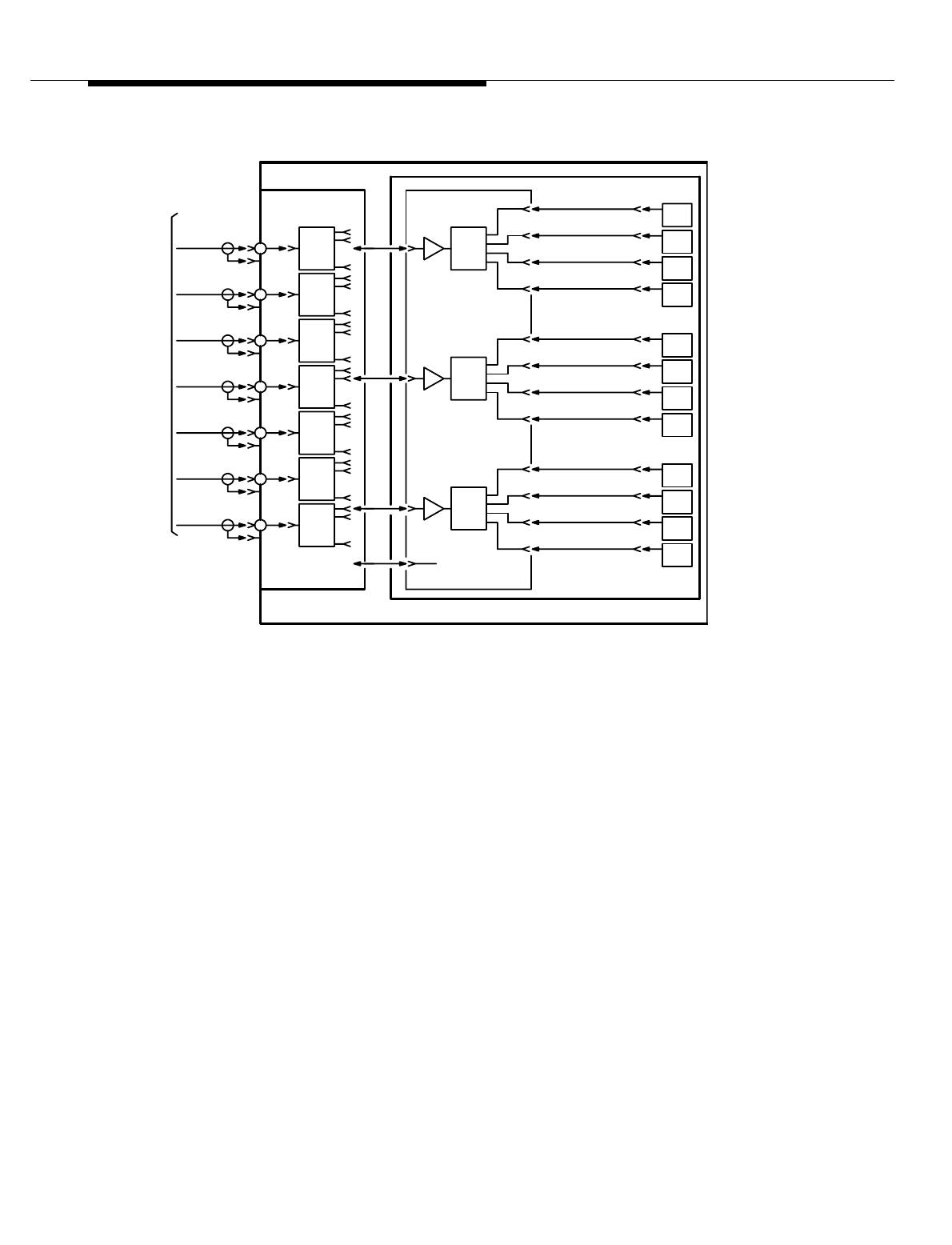
Lucent Technologies — Proprietary
See notice on first page
10-6 401-660-100 Issue 11 August 2000
Antenna Hardware Configurations
Figure 10-2. Interconnection Panel Assembly
/
DIV 01 Rx RF SIG/
DIV 01 Rx RF SIG/
DIV 01 Rx RF SIG
A. FIXED ANTENNA CONNECTION
11
10
RCU
/DIV 01
/DIV 01
/DIV 01
/DIV 01
/DIV 01
/DIV 01
RAMES
(ZETA)
(DELTA)
DVDR
1:9
/
/
Rx ANT "2"
Rx ANT "1"
Rx ANT "0"
DIV 01
(GAMMA)
(BETA)
(ALPHA)
(OMNI)
RF PWR
NTF
NT
ROM
/
PRIMARY/GROWTH
P/O
RCF
RCU SHELF
NON-SWITCHABLE
P/O
Rx ANT "6"
Rx ANT "5"
Rx ANT "4"
ASSEMBLY
P/O
INTERCONNECTION
(EPSILON)
DIV 01 Rx RF SIG
DIV 01 RF RCVR/DVDR
BOARD
NC
Rx ANT "3"
/
/
0
RCU
RCU
9
8
RCU
RCU
RCU
7
6
5
4
RCU
RCU
RCU
RCU
3
2
1
RCU
RCU
1:4
DVDR
RF PWR
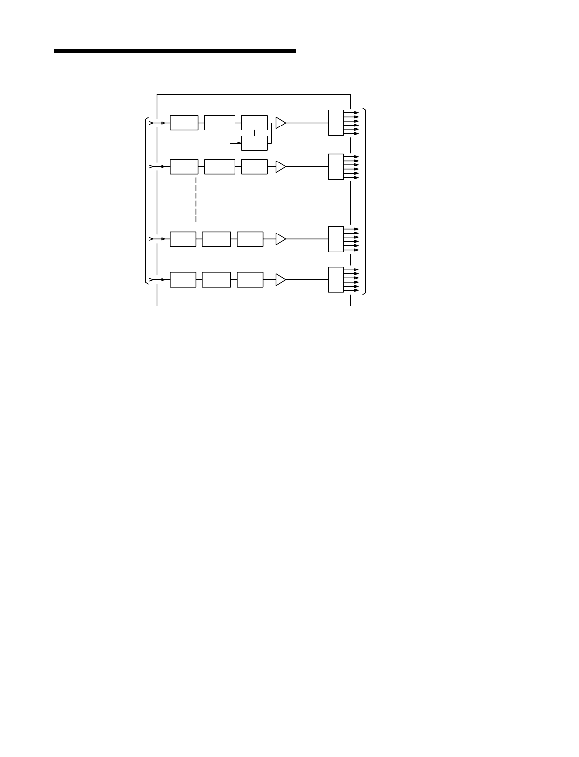
Lucent Technologies — Proprietary
See notice on first page
401-660-100 Issue 11 August 2000 10-7
Antenna Hardware Configurations
Figure 10-3. Antenna Interface
P/O AIF
ZETA RX-DIVERSITY 1
1:6
ANTENNAS
FROM
EPSILON
DELTA
GAMMA
BETA
ALPHA
COUPLER
TEST
FRAME
SET
RADIO
TO
BANDPASS
1:6
1:6
1:6
RF
SIG
CAL COUPLER
ZETA RX-DIVERSITY 0
SPLITTER
PRE-AMPLIFIER
LOW-NOISE
OMNI RX-DIVERSITY 1
OMNI RX-DIVERSITY 0
FILTER
NOTCH
FILTER
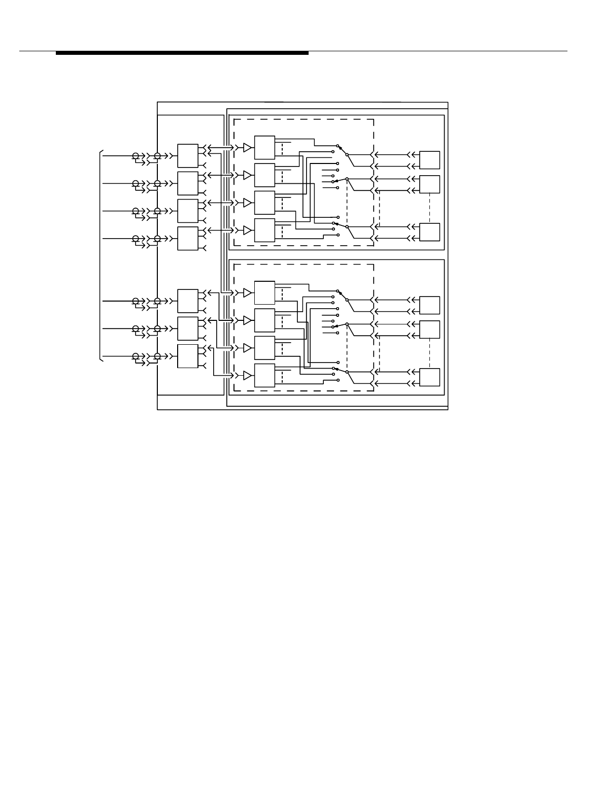
Lucent Technologies — Proprietary
See notice on first page
10-8 401-660-100 Issue 11 August 2000
Antenna Hardware Configurations
Figure 10-4. Primary RCF Switch Antenna Connector
3-Sector Directive
Plus Omni
Antenna
Switching
Configuration
This description pertains to setup and locate radios only. In this configuration, the
switchable antenna connection option is used for the receive path (see
Figure 10-4). With the switchable antenna connection option, each Radio Channel
Unit (RCU) on the shelf can switch receive paths to any one of 4 available
antennas. Receive inputs from the AIFs are coupled through 1:9 RF power
dividers in the Interconnection Panel Assembly to 1:12 power dividers on a BBM1
circuit board on the RCU shelf. One board is used for each of the two diversities.
Each board has 12 single-pole, four-position Radio Frequency (RF) switches.
Each switch is associated with and controlled by an RCU.
The control lines to the switches in the two receive diversity paths associated with
the same RCU are connected in parallel and, therefore, controlled simultaneously.
Fixed antenna connections are used in the transmit path.
RAMES
(B) SWITCHABLE ANTENNA CONNECTION
P/O PRIMARY RCF
ASSEMBLY
INTERCONNECTION
NTF
NT
ROM
P/O
ANT "3"
(BETA)
ANT "2"
(ALPHA)
ANT "1"
DIV 0/1
DIV 0/1
DIV 0/1
(OMNI)
ANT "0"
INTERCONN
RX SIG IN
RX SIG IN
RX SIG IN
ASSEM
DIV 0/1
RX SIG IN
(ZETA)
ANT "6"
ANT "4"
ANT "5"
(DELTA)
DIV 0/1
DIV 0/1
(GAMMA)
DIV 0/1
(EPSILON)
RX SIG IN
RX SIG IN
P/O
RX SIG IN
DVDR
RF PWR
1:9
DVDR
RF PWR
1:9
SW CONT SIG
GAMMA 0
RCU
SHELF "1"
(RCU SWITCHABLE SHELF)
RX RF SIGSW-0
DIV 0/1 RF RCVR AMPL/4X12 SWITCH/CMBR BOARD
BETA
ALPHA
OMNI
DVDR
RF PWR
1:12
P/O DUAL-SHELF RCU ASSEMBLY
1:12
SW CONT SIG 1
RCU
SW-1 RX RF SIG
SW CONT SIG
SW CONT SIG
SW CONT SIG
11
1
SW-11
RCU
RX RF SIG
RCU
RX RF SIGSW-1
SW CONT SIG
ZETA 0
11
RCU
RCU
SHELF "2"
(RCU SWITCHABLE SHELF)
RX RF SIG
SW-11 RX RF SIG
EPSILON
DELTA SW-0
OMNI
DIV 0/1 RF RCVR AMPL/4X12 SWITCH/CMBR BOARD
DVDR
RF PWR

Lucent Technologies — Proprietary
See notice on first page
401-660-100 Issue 11 August 2000 10-9
Antenna Hardware Configurations
6-Sector Directive
Plus Omni
Antenna
Switching with
Dual-Radio
Solution
This description pertains to setup and locate radios only. In this configuration (see
Figure 10-4), the hardware on the two shelves is the same as it is in the 3-sector
configuration; the differences are in the way the connections are made to the
AIFs. Fixed antenna connections are used for the transmit paths, and the
switchable antenna connection option is used for each of the two diversities in the
receive paths.
Inputs from the Omni antenna and directive antennas 1 through 6 are coupled
through 1:9 RF power dividers on the Interconnection Panel Assembly to BBM1
circuit boards on the Radio Channel Unit (RCU) shelves. One BBM is used for
each of the two diversities. The BBM1 boards on shelf 1 are connected to the
interface circuits of the Omni antenna and to directive antennas 1 through 3; the
boards on shelf 2 are connected to the Omni antenna and to directive antennas 4
through 6.
3- or 6-Sector
Directional
Antenna
Switching with
Simulcast Setup
In this configuration (see Figure 10-5), the hardware on the two shelves is the
same as it is in the omni setup 3- or 6-sector configurations; the difference is that
an omni antenna is not required for the setup radios. For 3-sector configurations,
the “simulated omni” signal is connected from a 6:1 combiner in AIF0 to a
connector in the RCF Interconnection Panel Assembly and through a 2-dB pad to
the BBM1 board. For 4-, 5-, or 6-sector configurations, the 2-dB pad is replaced by
a 1:2 divider. The combination of a 6:1 combiner and 2-dB pad and a 6:1
combiner and 1:2 divider are roughly equivalent to the loss of the 1:9 divider they
replace. The simulated omni signal is sent to the upper Switchable Radio Shelf or,
through the 1:2 divider, to both the upper and lower Switchable Radio Shelves.
The 6:1 combiner output signal simulates the omnidirectional setup antenna
signal of an omnidirectional setup/directional voice Cell Site, thereby eliminating
the need for an omnidirectional antenna dedicated to the setup function.
All-
Omnidirectional
Configuration
The basic all-omnidirectional configuration (see Figure 10-6) consists of one voice
channel transmit antenna, one optional setup transmit antenna to handle
transmission and paging signals over the entire cell,* and two receive antennas.
The receive antennas feed all Cell Site voice channel radios, setup radios, and
analog locate radios.
In an all-omnidirectional configuration, up to seven voice channel transmit
antennas are possible via the multiple-LAC feature. The multiple-LAC feature
allows up to seven LACs and seven transmit antennas to be associated with one
antenna face. The maximum number of transmit antennas at a Series II Cell Site
is 7.
* The basic all-omnidirectional configuration described here requires omnidirectional setup. There are three setup
configuration options—omnidirectional setup, directional setup, and simulcast setup.
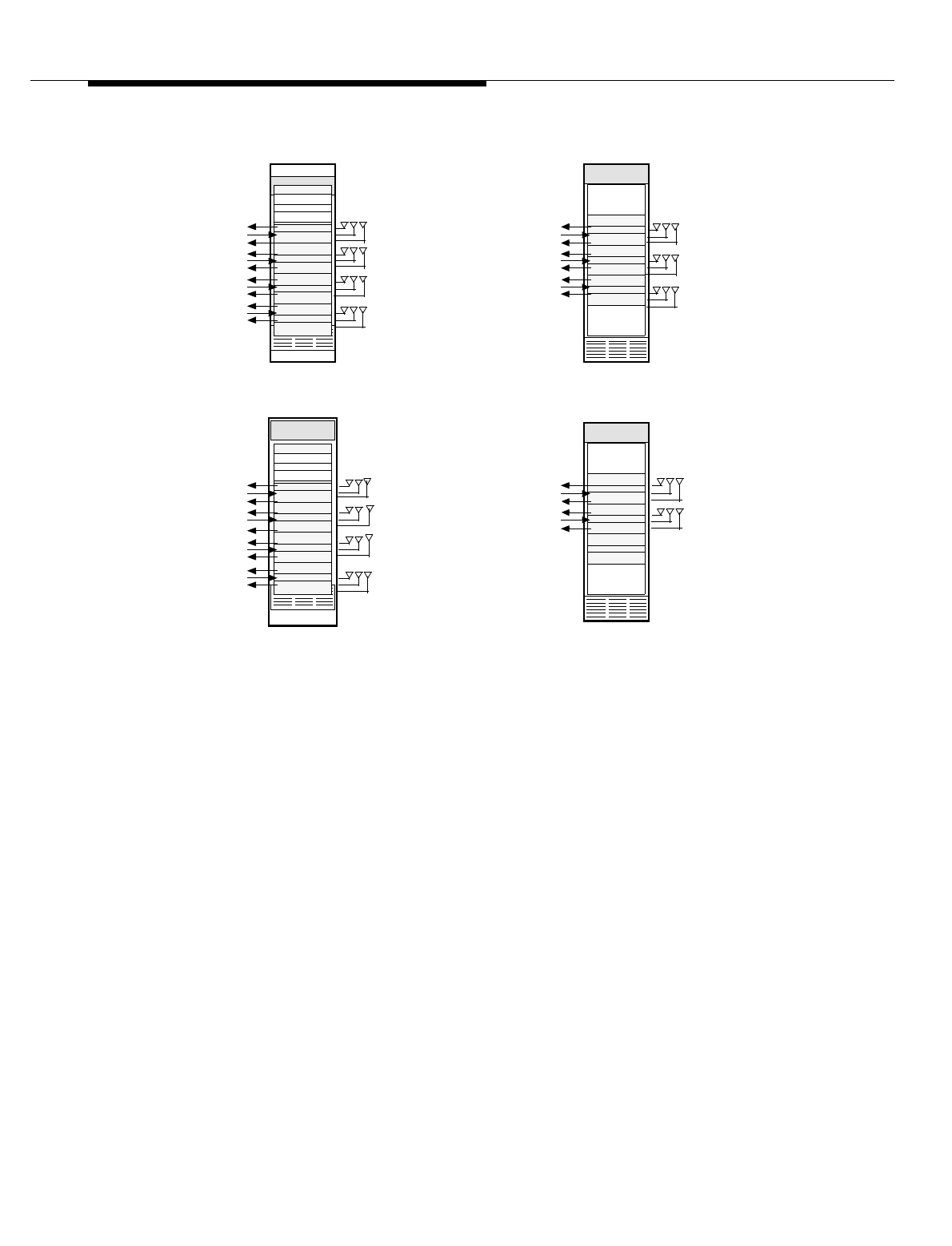
Lucent Technologies — Proprietary
See notice on first page
10-10 401-660-100 Issue 11 August 2000
Antenna Hardware Configurations
.
Figure 10-5. Mapping of Antenna Faces to Antenna Sets for the
Various Setup Options
All-Directional
Configuration In general, it will be necessary ultimately to sector omni cells to minimize
interference and provide increased system performance quality. Sectoring (see
Figure 10-5) is normally done with 120-degree directional antennas, where three
transmit antennas are used to cover the full 360 degrees. Sectoring may also be
done with 60-degree directional antennas, where six transmit antennas are used
to cover the full 360 degrees.
GROWTH—AIF1
RX 0 RX 1TX
RX 0 RX 1
TX
ANT 5
ANT 4
B. SERIES II Cell Site WITH DIRECTIONAL OR SIMULCAST SETUP
Ref Freq Gen
Rcvr Cal Gen
PRIMARY—AIF0
RX 0 RX 1TX
RX 0 RX 1TX
RX 0 RX 1
TX
RX 0 RX 1
TX
ANT 0
ANT 1
ANT 2
Rad Sw Panel ALPHA
BETA
GAMMA
EPSILON
ZETA
RCF
LAC 5
RCF
RCF
LAC 4
RCF
RCF
LAC 3
RCF
RCF
LAC 2
RCF
RCF
LAC 1
RCF
RCF
LAC 0
RCF
GROWTH—AIF1
RCF
LAC 6
RCF
RCF
LAC 5
RCF
RCF
LAC 4
RCF
ANT 5
ANT 6
ANT 4
A. SERIES II Cell Site WITH OMNIDIRECTIONAL SETUP
Ref Freq Gen
Rcvr Cal Gen
RCF
LAC 3
RCF
RCF
LAC 2
RCF
RCF
LAC 1
RCF
RCF
LAC 0
RCF
PRIMARY—AIF0
RX 0 RX 1TX
RX 0 RX 1
TX
RX 0 RX 1TX
RX 0 RX 1TX ANT 0
ANT 1
ANT 3
ANT 2
Radio Sw Panel OMNI
ALPHA
BETA
GAMMA
DELTA
EPSILON
ZETA
RX 0 RX 1TX
RX 0 RX 1
TX
RX 1TX
RX 0
ANT 3 GAMMA
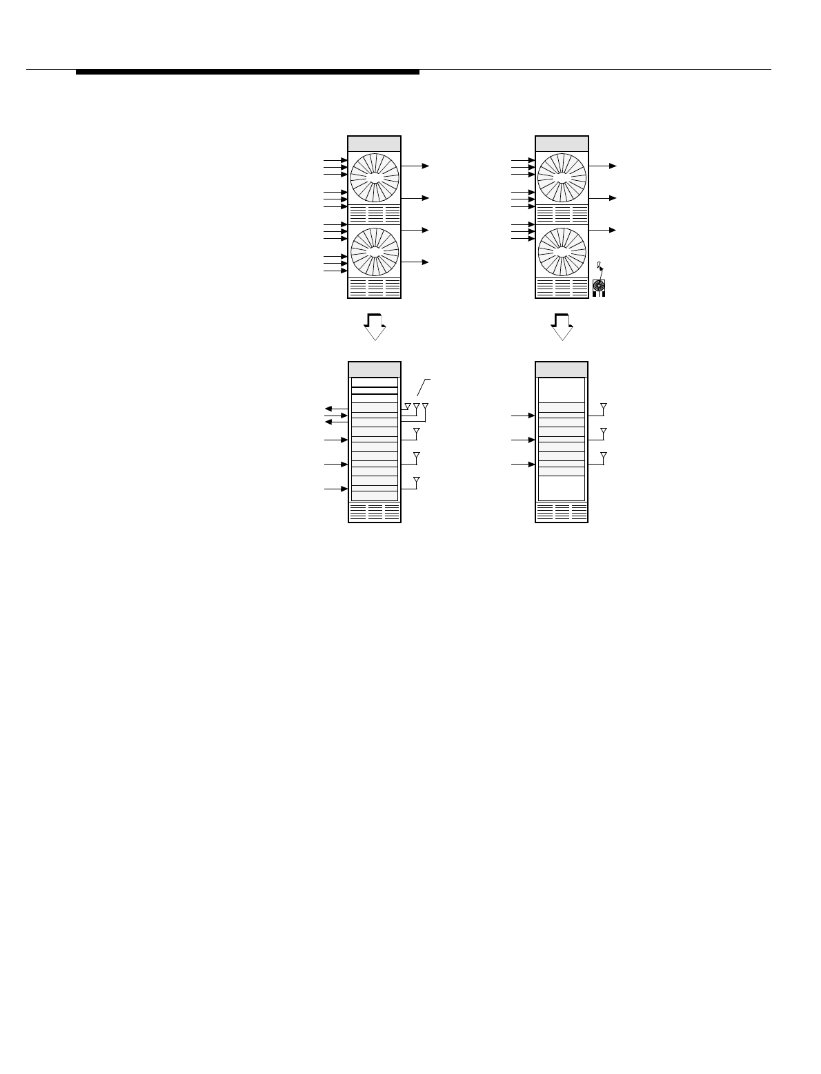
Lucent Technologies — Proprietary
See notice on first page
401-660-100 Issue 11 August 2000 10-11
Antenna Hardware Configurations
Figure 10-6. Omnidirectional Cell Site Having Seven Transmit Antennas
The basic all-directional configuration consists of:
1. Three sets of 3-sector (120-degree) directional antennas or six sets of 6-
sector (60-degree) directional antennas,
2. One optional omnidirectional setup transmit antenna to handle
transmission and paging signals over the entire cell, and
3. Two optional omnidirectional setup receive antennas. Each physical
antenna face has one or two directional transmit antennas and two
directional receive antennas.
Thus, when a cell is sectored, there are at least nine 120-degree directional
antennas or 18 60-degree directional antennas, plus the optional three
omnidirectional setup antennas to complete the configuration—for a maximum of
21 antennas at a Series II Cell Site.
Growth—AIF1
LAC 6
LAC 5
LAC 4
TX
TX
TX
VOICE TX
VOICE TX
VOICE TX
Ref Freq Gen
Rcvr Cal Gen
LAC 3
LAC 2
LAC 1
RCF
LAC 0
RCF
Primary—AIF0
TX
TX
TX
RX 0RX 1TX ANT 0
VOICE TX
VOICE TX
VOICE TX
Radio Sw Panel OMNI
LAC
=
RCF2
RCF1
RCF0
AIF0
RCF2
RCF1
RCF0
RCF2
RCF1
RCF0
RCF2
RCF1
RCF0
AIF0
AIF0
AIF0
Primary—LAF0
AIF1
RCF2
RCF1
RCF0
RCF2
RCF1
RCF0
RCF2
RCF1
RCF0
AIF1
AIF1
Growth—LAF1
LAC 3 OUT
LAC 1 OUT
LAC 2 OUT
LAC 0 OUT
LAC 4 OUT
LAC 5 OUT
LAC 6 OUT
LAM
=
Legend:
LAC 0
LAC 2
LAC 4
LAC 6
Setup TX (Note)
Setup TX May Also Carry Voice Channels.
Note:

Lucent Technologies — Proprietary
See notice on first page
10-12 401-660-100 Issue 11 August 2000
Antenna Hardware Configurations
If duplexers are used on each antenna face, the maximum number of antennas is
reduced to 14. A duplexer is a combined receive and transmit filter panel that
connects to a single antenna. Functionally, the receive and transmit circuits are
the same as the separate receive and transmit filter panels, except that the
duplexer provides a combined receive/transmit antenna port. Thus, the duplexer
permits multiplexing of one of the receive paths—usually diversity 0—with the
transmit path of an antenna face, thereby reducing the required number of
antennas from three to two per face.
A 3-sector cell has three physical antenna faces, which are functionally
designated alpha, beta, and gamma. Usually, the antenna face whose center line
is pointing north is called alpha. The antenna face clockwise from alpha is called
beta, and the antenna face clockwise from beta is called gamma.
A 6-sector cell has six physical antenna faces, which are functionally designated
alpha, beta, gamma, delta, epsilon, and zeta. The antenna face clockwise from
gamma is called delta, the antenna face clockwise from delta is called epsilon,
and the antenna face clockwise from epsilon is called zeta.
Figure 10-1 shows how the antenna faces map to antenna sets for the
omnidirectional, directional, and simulcast setup options. Notice that antenna 0
does not necessarily mean antenna omni; antenna 0 may also mean antenna
alpha—at a Cell Site having directional or simulcast setup.
The Cell Site RCC identifies the transmit and receive antennas associated with an
antenna face by the Radio Test Unit Switch Panel (RSP) switch positions used to
test them. The RSP cable connections to transmit antennas 0 through 6 are fixed,
but the RSP cable connections to receive antennas 0 through 6 for diversity 0 and
diversity 1 are not fixed and depend upon whether antenna 0 means antenna
omni or antenna alpha. The RSP cable connections at a Series II Cell Site when
antenna 0 means antenna omni (applicable to Cell Sites having omnidirectional
setup). The RSP cable connections at a Series II Cell Site when antenna 0 means
antenna alpha (applicable to Cell Sites having).

Lucent Technologies — Proprietary
See notice on first page
401-660-100 Issue 11 August 2000 10-13
Antenna Hardware Configurations
Radio Transmission and Reception
The Cell Site receives digital-voice signals via a T1 line, modulates and up-
converts the signals to RF, and then transmits the RF output signals over the air
interface to a mobile station. In the mobile-transmit direction, the Cell Site receives
RF input signals from a mobile station via the receive antennas (two inputs for
diversity), then filters, amplifies, and recovers the original mobile data for
transmission over a T1 line to the MSC.
Two-branch spatial diversity on reception is achieved by providing two receive
antennas physically separated by about 3 to 4 meters so that their received
signals are not correlated. When one antenna receives a multipath fade, the other
antenna probably will not.
RF Transmitter
Interfaces There are two distinct RF transmitter interface configurations: the all-
omnidirectional antenna configuration and the all-directional (120- or 60-degree)
antenna configuration. The RF output can be transmitted through an omni-
transmit antenna or through a transmit antenna on one of the physical antenna
faces of the directional antennas. The low-power RF transmissions from multiple
radios are combined and amplified by a LAC and sent through a transmit filter
panel to the transmit antenna (see Figure 10-7).
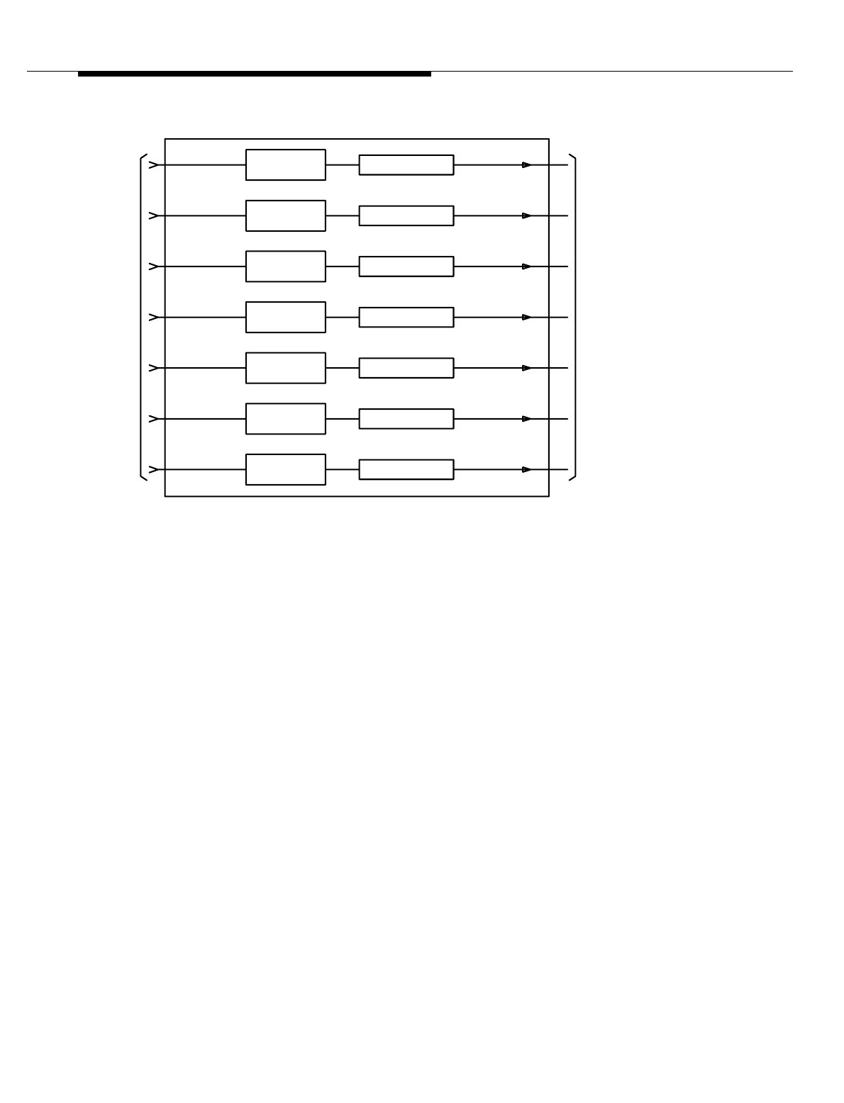
Lucent Technologies — Proprietary
See notice on first page
10-14 401-660-100 Issue 11 August 2000
Antenna Hardware Configurations
Figure 10-7. Antenna Coupler
RF Receiver
Interfaces There are two distinct RF receiver interface configurations: the all-omnidirectional
antenna configuration and the all-directional (120- and 60-degree) antenna
configuration. The RF input can be received through a pair of omni-receive
antennas or through a pair of receive antennas on one of the physical antenna
faces of the directional antennas. The RF input signals pass through receive filter
panels to RF power dividers, where the signals are divided and cabled to the
diversity 0 and diversity 1 receiver sections (identical receivers) of the radios.
2 Branch
Intelligent
Antenna, Feature
IDentification
(FID) #3145
What “2 Branch” means in 2 Branch Intelligent Antennas
This chapter covers the “2 Branch Intelligent Antennas” feature, which has
Feature IDentification (FID) #3145. The “2 Branch Intelligent Antennas” feature
was developed to deliver better voice quality on the transmission link between the
mobile and the base station. “2 branch” refers to the 2 existing paths, 1 path from
each of the 2 diversity receive antennas, to the Enhanced Digital Radio Unit’s
(EDRU) or the Dual Radio Module (DRM). While a four branch reverse link system
would have yielded a greater improvement in voice quality, it would have required
extensive redesign of the existing Series II architecture. Therefore, the 2 branch
system, which required no redesign, was implemented.
P/O AIF
ANTENNAS
TO TX
Tx"6"
Tx"5"
Tx"4"
Tx"3"
Tx"2"
Tx"1"
Tx"0"
FILTER
TX BANDPASS TEST COUPLER
AF
ROM

Lucent Technologies — Proprietary
See notice on first page
401-660-100 Issue 11 August 2000 10-15
Antenna Hardware Configurations
How the Enhanced Digital Radio Unit (EDRU) is used to support 2
Branch Intelligent Antennas
The 2 Branch Intelligent Antennas feature is implemented in the Enhanced Digital
Radio Unit’s (EDRU’s) software. However, the 2 Branch Intelligent Antennas
Feature does not add a new Non-Volatile Memory (NVM) image. Both of the
existing Enhanced Digital Radio Unit’s (EDRU’s) Non-Volatile Memory (NVM)
images (packet pipe & non-packet pipe) incorporate the new software. The
Enhanced Digital Radio Unit’s (EDRU) is used in the Series II Classic, Series IIe,
Series IIm, Series IImm, and PCS TDMA Minicell products. The 2 Branch
Intelligent Antennas Feature is not intended for and does not work with Lucent’s
analog products. No extra Radio Frequency (RF) hardware is required to
implement this feature and it does not impact the existing base station’s Radio
Frequency (RF) footprint, antennas, size, or power.
What “Intelligent” means in 2 Branch Intelligent Antennas
“Intelligent Antennas” refers to an entire system comprised of a radiating structure
with antennas for transmit and receive, which are connected via Radio Frequency
(RF) cables to a Digital Signal Processor (DSP) (within the Enhanced Digital
Radio Unit’s (EDRU) which has the ability to execute intelligent algorithms that
process the Radio Frequency (RF) signals to improve system performance.
The Adaptive
Interference
Rejection
Technique
The 2 Branch Intelligent Antennas Feature uses the “Adaptive Interference
Rejection,” technique, also known as digital beamforming, for optimally combining
the 2 diversity receive antennas. Adaptive Interference Rejection captures the
Radio Frequency (RF) signals from the antenna elements and converting them
into 2 streams of binary I and Q signals, which together represent the amplitudes
and phases of the signals received by the antenna. The adaptive interference
rejection is carried out by weighting these digital signals, thereby adjusting their
amplitudes and phases, such that when they are added together, it maximizes the
Signal-to-Noise Ratio (SINR) for the desired signal. A typical digital adaptive
interference rejection system consists of an array of antenna elements,
independent receivers for the individual antenna elements, and one or more
digital signal processors. This feature is a software enhancement only and
makes use of the existing 2 branch architecture for receive diversity built into the
Enhanced Digital Radio Unit’s (EDRU). This feature works for only the reverse
link in the Enhanced Digital Radio Unit’s (EDRU). All processing is done at
baseband.
Performance with 2 Branch Intelligent Antennas
The 2 Branch Intelligent Antennas Feature provides better voice quality in an
interference dominated environment on the reverse link (Mobile to Base Station)
only. The 2 Branch Intelligent Antennas feature yields a 3 dB performance
enhancement in the reverse link C/I in an interference limited environment when
compared to the existing maximal ratio combining technique used in the

Lucent Technologies — Proprietary
See notice on first page
10-16 401-660-100 Issue 11 August 2000
Antenna Hardware Configurations
differential detection and trellis equalization paths. On average, co-channel
interference is expected to decrease by a nominal 3 dB compared to the classic
diversity scheme in the Enhanced Digital Radio Unit’s (EDRU) in an interference
limited environment. The level of improvement depends on the distribution of co-
channel users in neighboring cells. This feature allows each 30 kHz TDMA
channel, through software processing, to reduce/eliminate the effects of co-
channel interference within the field of view of the Enhanced Digital Radio Unit’s
(EDRU). Baseband processing is able to combine the spatially separated
diversities for interference rejection.
The 2 Branch Intelligent Antennas Feature equals the performance of the existing
maximal ratio combining technique when used in a noise limited environment. The
feature does not increase the existing capacity or range of the base station in a
noise limited environment. A tower top Low Noise Amplifier (LNA), however,
provides range extension on the reverse link in a noise limited environment. Using
this feature together with a tower top Low Noise Amplifier (LNA) would yield
interference rejection and range extension on the reverse link. However, the
purpose of this feature is to improve voice quality in an interference limited
environment, not a noise limited environment. Activation of this feature does not
degrade the existing performance of the Enhanced Digital Radio Unit’s (EDRU) in
a noise limited environment.
Digital Locate under 2 Branch Intelligent Antennas 0
The 2 Branch Intelligent Antennas Feature should not be implemented on the
digital locate radio. Locate radios are used to determine if a call will be placed on
a certain channel. Selection criteria should be based on the best channel in a
noise limited environment. Calls should not be placed on channels with a lot of
interference.
2 Branch Intelligent Antennas Testing 0
Testing of the 2 Branch Intelligent Antennas on the Enhanced Digital Radio Unit’s
(EDRU) feature is done in maximal ratio combining mode. Current testing in the
Enhanced Digital Radio Unit’s (EDRU) only tests one branch of the dual diversity
receive paths at a time. To eliminate the development of a new testing routine with
minimal gains, the Enhanced Digital Radio Unit’s (EDRU) should be switched
back to maximal ratio combining mode and tested one branch at a time.
2 Branch Intelligent Antennas Phased Release
The 2 Branch Intelligent Antennas Feature is a phased release. Phase 1
implements this feature on the digital traffic radio and incorporates the adaptive
interference rejection technique into the differential detection path of the Digital
Signal Processor (DSP).

Lucent Technologies — Proprietary
See notice on first page
401-660-100 Issue 11 August 2000 10-17
Antenna Hardware Configurations
2 Branch Intelligent Antennas Feature Activation 0
The 2 Branch Intelligent Antennas Feature is activated on a per Cell Site Feature
Activation File with Qualifiers (QFAF) basis. The feature is enabled from the
Mobile Switching Center (MSC) by a translation to select adaptive interference
mode or maximal ratio combining mode on a cell by cell basis. All Enhanced
Digital Radio Unit’s (EDRUs) at the cell site have the feature turned on or off on a
cell by cell basis using RC/V.

Lucent Technologies — Proprietary
See notice on first page
10-18 401-660-100 Issue 11 August 2000

Lucent Technologies — Proprietary
See notice on first page
401-660-100 Issue 11 August 2000 11-1
11
Cell Site Hardware Functions and
Interconnections
Contents
■Contents 11-1
■Introduction 11-5
Radio Control Complex (RCC) 11-5
Digital Signal (DS1) Units 11-6
Digital Facilities Interface (DFI) Units 11-6
Clock And Tone (CAT) Units 11-7
Radio Frame Set 11-7
RCF Architecture and Bus Structure 11-9
System bus 11-9
Update bus 11-9
TDM buses 11-9
■Data Link and Voice
Path Connections11-14
T1/E1 Communications 11-14
T1 Line Interface 11-16
E1 Line Interface 11-16
■Line Interface Connections at the Cell 11-17
■Data Link Configurations 11-21
One DS1/DFI Unit and One Data Link 11-21

Lucent Technologies — Proprietary
See notice on first page
11-2 401-660-100 Issue 11 August 2000
Cell Site Hardware Functions and Interconnections
One DS1/DFI Unit and Two Data Links 11-21
Two DS1/DFI Units and Two Data Links 11-21
Remote Data Link Reconfiguration 11-21
■ External Interfaces to the Series II Cell Site 11-22
Voice Trunks from the Digital Cellular Switch (DCS) 11-22
Time Division Multiplexed Buses 11-22
TDM Bus Operation 11-22
TDM Bus Addresses 11-24
■TDM Bus Communications: the Archangel/Angel Concept 11-26
Angel 11-27
Archangel 11-27
■Sanity And Control Interface 11-28
■NPE and SNPE 11-31
■Synchronization of the Cell Site to the MSC 11-32
TDMCKSEL 11-36
TDMCKFAIL 11-36
TDMCLK 11-36
TDMFR 11-36
TDMSYNC1 11-36
TDMSYNC2 11-36
■Mobile Switching Center (MSC) to Cell Site Communications 11-37
■ DS1, DFI, and CAT Circuit Descriptions 11-38
DS1 (TN171) Circuit Description 11-38
DFI (TN3500) Circuit Description 11-38
DFI (TN1713B) Circuit Operation 11-40
■ DFI Initialization Message for T1 Operation 11-42
D4 or ESF Framing 11-42
ZCS or B8ZS Line Format 11-46
Line-length Compensation Setting 11-46
Enable or Disable On-demand LLB or BLB Control 11-46
Select Synchronization Reference 11-47
Specify Idle Code 11-47
■DFI Initialization Message for E1 Operation 11-48
CEPT Framing with or without CRC-4 Error Checking 11-48
CCS or CAS Signaling Mode 11-48
HDB3 or Transparent Line Format 11-50

Lucent Technologies — Proprietary
See notice on first page
401-660-100 Issue 11 August 2000 11-3
Cell Site Hardware Functions and Interconnections
Enable or Disable On-demand LLB or BLB Control 11-50
Select Synchronization Reference 11-50
Select Idle Code 11-50
DFI Network-Update Talk Message 11-50
DFI Network-Update Listen Message 11-50
■DFI Status Indicators 11-51
Red LED 11-51
Yellow LED 11-51
Green LED 11-51
■CAT (TN170) Circuit Description 11-52
■Bus Clock Generation and Monitoring for the TDM Bus 11-55
■Maintenance Tone Generation 11-56
Maintenance Tone Detection and Measurement 11-57
■CAT Status Indicators 11-58
Red LED 11-58
Green LED 11-58
■Automatic Recovery Actions 11-59
■Hardware Error Handling Strategy 11-60
Immediate Action 11-60
All Tests Pass (ATP) Analysis 11-60
Single Time-period Analysis 11-60
Fail/Pass Analysis 11-60
Leaky Bucket Analysis 11-61
■RCC Hardware Errors and Recovery Actions 11-62
■DS1/DFI Hardware Errors and Recovery Actions 11-63
■ DS1/DFI and T1 Errors—Detailed Description 11-64
Loss Of Signal (LOS) 11-64
Blue Alarm 11-64
Red Alarm 11-64
Major Alarm 11-65
Yellow Alarm 11-65
■Fan Alarms 11-66
Preamp Fan 11-66
LineariZeR Fan Procedure 11-66
Major Alarm 11-66
Minor Alarm 11-67

Lucent Technologies — Proprietary
See notice on first page
11-4 401-660-100 Issue 11 August 2000
Cell Site Hardware Functions and Interconnections
LAU Fan Procedure 11-67
Major Alarm 11-67
Minor Alarm 11-67
Measuring the Linear Amplifier Unit (LAU) Fan Voltage 11-67
■DS1 Errors 11-68
Minor Alarm 11-68
Misframe Count 11-68
■DFI and E1 Errors - Detailed Description 11-69
Loss Of Signal (LOS) 11-69
Alarm Indication Signal (AIS) 11-69
Loss of Frame Alignment (LFA) 11-69
Loss of Multiframe Alignment (LMA) 11-70
10e-3 Error-ratio Alarm 11-70
Remote Frame Alarm (RFA) 11-70
Remote Multiframe Alarm (RMA) 11-71
10e-6 Error-Ratio Alarm 11-71
Slip Count 11-71
■CAT Hardware Errors and Recovery Actions 11-72
Call-Processing Errors and Recovery Actions 11-72
Diversity Imbalance Errors and Recovery Actions 11-72
Manual Recovery Actions 11-73
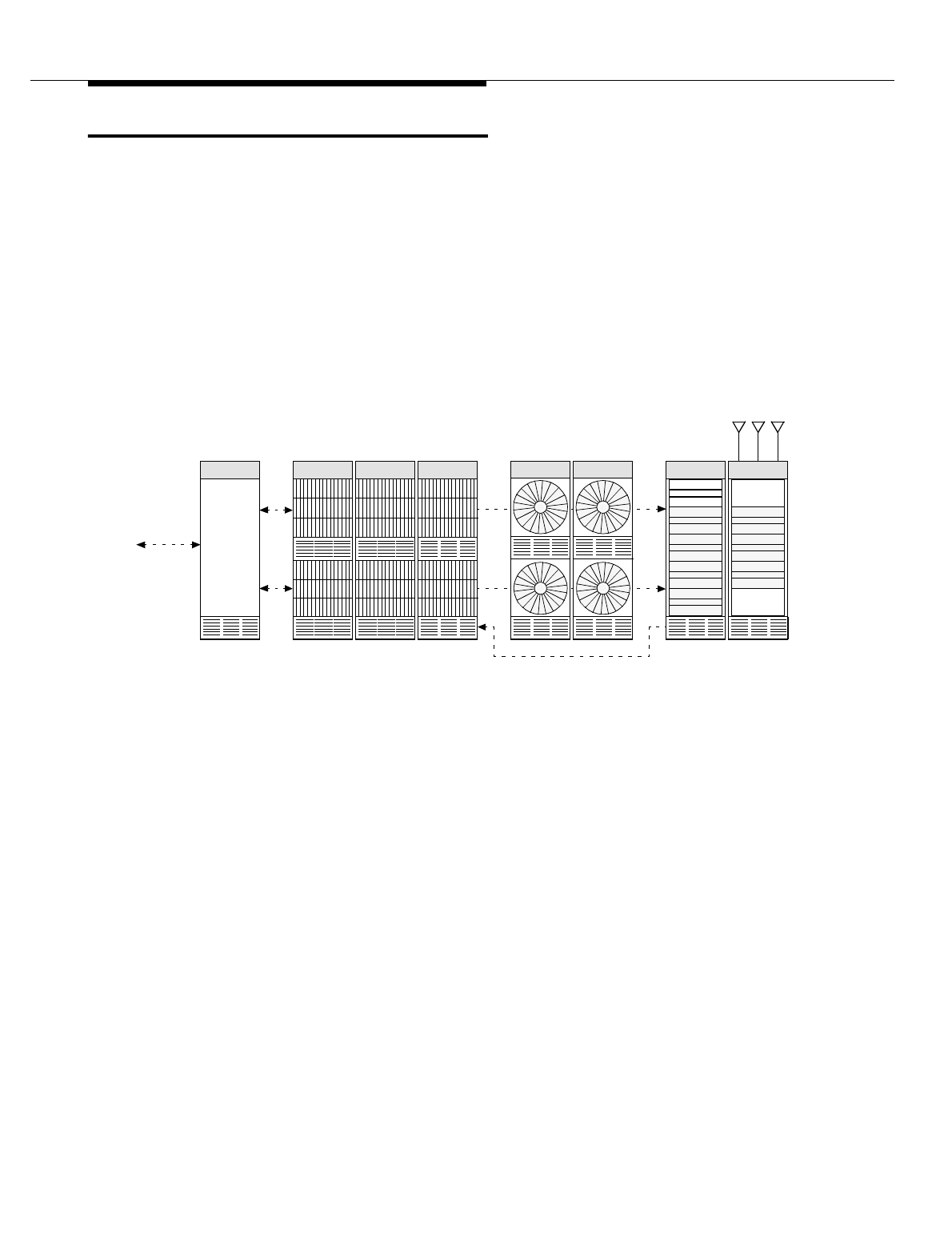
Lucent Technologies — Proprietary
See notice on first page
401-660-100 Issue 11 August 2000 11-5
Cell Site Hardware Functions and Interconnections
Introduction
The Series II Cell Site (See Figure 11-1) includes controllers, radios, wideband
linear amplifiers, antennas, and associated equipment for setting up and
completing cellular calls. It can support AMPS, TDMA, and CDMA simultaneously
through the same wideband linear amplifier and antennas.
Hardware elements common to AMPS, TDMA, and CDMA are the linear amplifier
frames (LAFs), the antenna interface frames (AIFs), and the hardware units
resident in the RCF (See Figure 11-2). The hardware units resident in the radio
channel frames (RCFs) are described in the following paragraphs.
Figure 11-1. Series II Cell Site Architecture
Radio Control
Complex (RCC) The RCC (See Figure 11-2) provides control of the Cell Site equipment and
performs call processing in conjunction with the ECP complex. Specifically, the
RCC performs the following tasks:
■Manages radio resources and speech trunks
■Gathers statistical information about the operation of the cell for network
management
■Maintains the service status of hardware and software entities within the
cell
TX TX
TX TX
RX
Primary
Radio
Channel
Frame 0
(RCF0)
Radio
Channel
Frame 1
(RCF1)
Growth Growth
Radio
Channel
Frame 2
(RCF2)
Antenna
Interface
Frame 0
(AIF0)
Antenna
Interface
Frame 1
(AIF1)
Facilities
Interface
Frame
(FIF)
Linear
Amplifier
Frame 0
(LAF0)
Linear
Amplifier
Frame 1
(LAF1)
Primary Growth Primary Growth
RX 0 RX 1TX
Radio Frame Set
DS-1
Voice
and
Data
Links

Lucent Technologies — Proprietary
See notice on first page
11-6 401-660-100 Issue 11 August 2000
Cell Site Hardware Functions and Interconnections
■Monitors subordinate hardware devices for detected faults
■Performs diagnostic tests on the Cell Site equipment
The Radio Control Complex (RCC) controls the entire Radio Frame Set (RFS).
The RCC is fully redundant and uses two identical processors, called RCC 0 and
RCC 1, as shown in Figure 11-2. Normally, one processor is active and one is
standby. Each processor contains a memory, Network Control Interfaces (NCIs) to
control the TDM buses, a Communications Processor Interface (CPI), an alarm
interface, and a system bus which connects all circuit packs. An update bus
interconnects the two processors within the RCC. Series II processors have
improved speed and memory capacity. The TDM buses are always installed "red
stripe up."
The RCC also provides the interface to pass Cell Site alarms to the MSC. These
alarms include hardware alarms/power alarms, fire and intrusion alarms, and
environmental alarms. Alarms are monitored by the alarm interface circuits
located in the RCC shelf of the primary Radio Control Frame (RCF). They include
the following:
■12 internal frame alarms
■18 user-assigned alarms
■12 frame alarms from each growth frame
■6 circuit alarms from the Antenna Interface Frame (AIF)
■Status alarms from each Linear Amplifier Circuit (LAC) in the Linear
amplifier Frame (LAFs)
All the user-assigned and the AIF alarms are connected to the primary RCF by
one connector. The status of the alarms originating in the LACs is scanned
periodically and alarm data is transmitted to the P-RCF by a dedicated connector.
Digital Signal
(DS1) Units DS1 units perform serial-to-parallel and parallel-to-serial data conversion between
the T1 lines and the one or two time-division multiplexed (TDM) buses that
connect the primary RCF to the growth RCFs. The DS1 units provide the T1 (1544
kbit/s) connectivity to the DCS. The TDM buses are always installed "red stripe
up."
Digital Facilities
Interface (DFI)
Units
The DFI unit performs serial-to-parallel and parallel-to-serial data conversion
between the T1 lines and the one or two TDM buses that connect the primary
RCF to the growth RCFs. A DFI may reside in any slot reserved for the DS1.
Unlike the DS1, which can terminate only one T1 line, the DFI can terminate up to
two T1 lines, although only one termination is currently supported. In addition, the
DFI can be configured to terminate E1 (2048 kbit/s) lines.
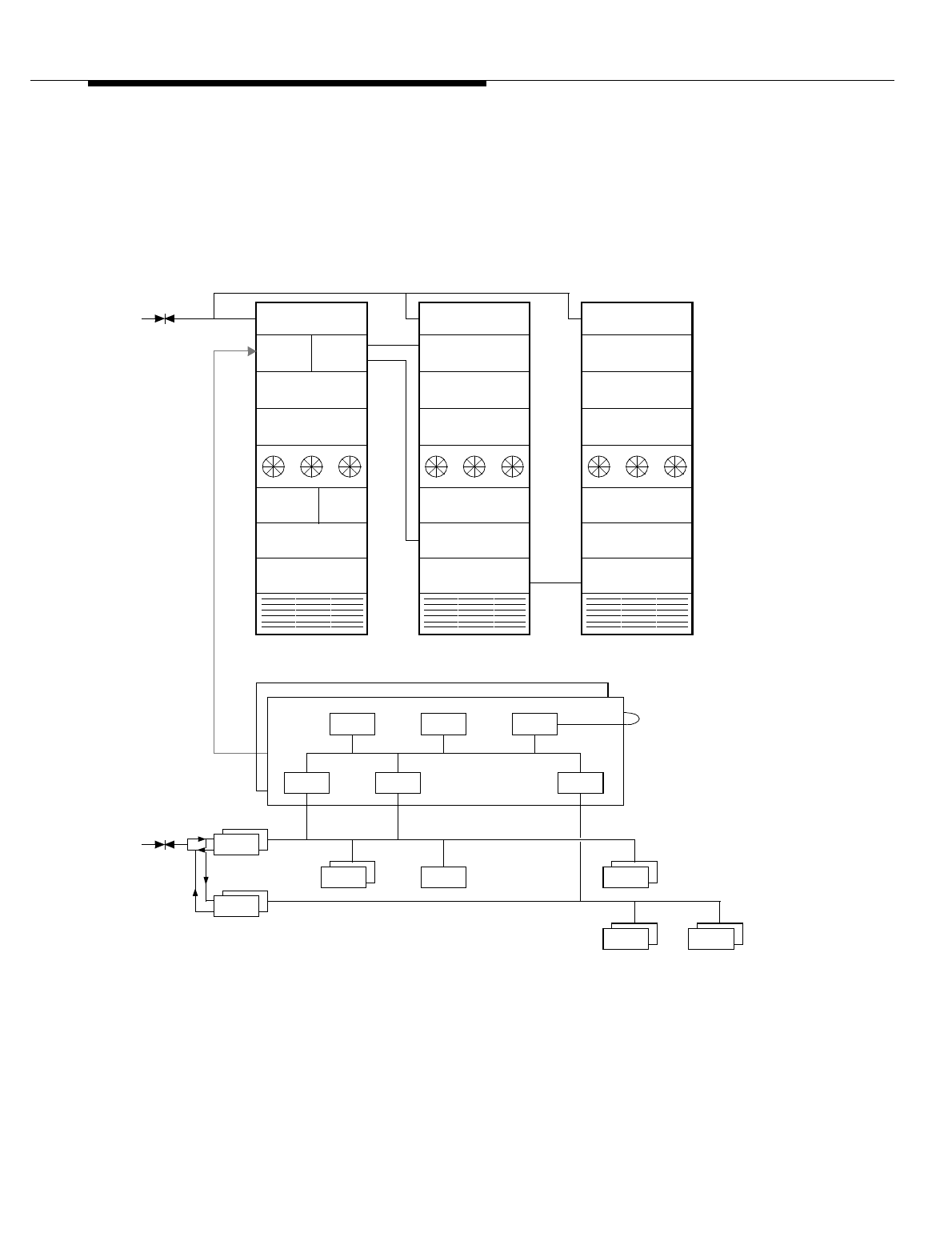
Lucent Technologies — Proprietary
See notice on first page
401-660-100 Issue 11 August 2000 11-7
Cell Site Hardware Functions and Interconnections
Clock And Tone
(CAT) Units The CAT unit generates the clock signals for the one or two TDM buses that
connect the primary RCF to the growth RCFs. The TDM buses are always
installed "red stripe up."
Radio Frame Set A radio frame set consists of a primary RCF and up to two growth RCFs. A radio
frame set is capable of accommodating up to 14 DS1 or DFI units, four CAT units,
200 AMPS radio channel units (RCUs) or single-board RCUs (SBRCUs) (includes
setup, locate, and voice radios), and one AMPS radio test unit (RTU).
Figure 11-2. Radio Frame Set Architecture and Bus Structure
CAT
(2 CATs)
12 RCU
12 RCU
12 RCU
12 RCU
12 RCU
12 RCU
Interconnection
Panel Assembly
12 RCU
12 RCU
12 RCU
12 RCU
12 RCU
12 RCU
Interconnection
Panel Assembly
RCC0 RCC1
Primary—RCF0 Growth—RCF1 Growth—RCF2
8 RCU
12 RCU
12 RCU
12 RCU
12 RCU
TDM0
TDM1
TDM1
Interconnection
Panel Assembly
Update
Bus
MemAFI CPU
System
Bus 0
RCC1
RCC0
T1
1 RTU
Shelf 0
Shelf 1
Fans
Shelf 3
Shelf 4
Shelf 5
Shelf 2
NCI1
RCU
(≤104 RCUs)
RTU
CPI NCI0
CAT
(2 CATs)
Note: Cat units are redundant for both TDM0 and TDM1.
DS1
(≤7 DS1s)
DS1
T1 DS1
(≤7 DS1s)
DS1
TDM0
TDM1
RCU
(≤96 RCUs)

Lucent Technologies — Proprietary
See notice on first page
11-8 401-660-100 Issue 11 August 2000
Cell Site Hardware Functions and Interconnections
A radio frame set can also accommodate TDMA digital radio units (DRUs,
EDRUs) and a TDMA radio test unit (TRTU). A radio frame set can hold up to 96
DRUs. The maximum number of EDRUs that can be installed in a radio frame set
has yet to be determined.
Any combination of RCUs, SBRCUs, DRUs, and EDRUs can reside in the primary
RCF or in a growth RCF with the following constraint: no more than five EDRUs
are allowed in the same radio shelf due to DC power limitations. All four radio
types can sit side-by-side in the same radio shelf. The TRTU, when installed, sits
right next to the RTU in the radio test shelf. The DRU occupies two adjoining RCU
slots, the EDRU occupies one RCU slot, and the TRTU occupies two adjoining
RTU slots.
CDMA radios are installed in their own growth RCF, which is designed to house 12
CDMA radios—two (redundant) radios per shelf. (One CDMA radio is active and
one is standby). CDMA radios cannot be installed in the primary RCF, nor can
they be intermixed with RCUs, SBRCUs, DRUs, or EDRUs in the same growth
RCF. Since there can be up to two growth RCFs in a radio frame set, the Series II
Cell Site can accommodate up to 24 CDMA radios.
A radio frame set consists of at most three RCF frames: a primary RCF and one
or two growth RCFs. One or both of the growth RCFs may be CDMA growth
frames.
The plug-in units, or circuit boards, are physically located by shelf and slot
numbers. Slot numbers are indicated at various points along the horizontal run.
A Radio Frame Set (RFS) consists of at least a primary Radio Channel Frame
(RCF 0) and a maximum of two "growth" RCFs (RCF 1 and RCF 2). All RCFs
contain 6 radio shelves, shelves 0 through 5. The entire RFS is controlled by the
Radio Control Complex (RCC), which is located in the uppermost shelf (Shelf 0) of
the P-RCF.
In the P-RCF, shelves 1, 2, 4, and 5 can each support 12 Radio Channel Units
(RCUs). Shelf 3 of the P-RCF contains the TDMA Radio Test Unit (TRTU),
required to test the radio units, and therefore can only house up to 8 RCUs.
Altogether, RCF 0 can house 56 RCUs or Enhanced Digital Radio Units (EDRUs)
(which, like the RCU use only 1 radio slot apiece) (12 x 4 + 8); or RCF 0 can
house 28 Digital Radio Units (DRUs), which use 2 radio slots apiece.
Each of the Growth RCFs is capable of accommodating up to a total of 12 RCUs
or EDRUs on each of its 6 radio shelves, or 72 RCUs or EDRUs apiece (12 x 6); or
a Growth RCF can house 36 DRUs.
TDM bus 0 connects all the radio shelves in RCF 0 and the 4 upper shelves, 0 thru
4, in RCF 1. That makes the number of radio slots covered by TDM bus 0 equal to
104. That many slots could house 104 RCUs or EDRUs or 52 DRUs.

Lucent Technologies — Proprietary
See notice on first page
401-660-100 Issue 11 August 2000 11-9
Cell Site Hardware Functions and Interconnections
TDM bus 1 Connects the 2 lowest radio shelves in RCF 1 and all the radio shelves
in RCF 2. That makes the number of radio slots covered by TDM bus 1 equal to
96. That many slots could house 96 RCUs or EDRUs or 48 DRUs.
The TDM buses are always installed "red stripe up."
The number of radios and/or radio channels that TDM buses 0 and 1 support may
or may not be equal to the number of radio units that physically fit into those
shelves that are covered by either of the buses.
RCF Architecture
and Bus Structure The RCC (See Figure 11-2), which resides on the uppermost shelf (shelf 0) of the
primary RCF, consists of two identical controllers. One controller is active (on-line)
and one is standby (off-line).
System bus
Each RCC controller makes use of a dedicated system bus over which all of the
units that make up the controller communicate. The two system buses (0 and 1)
are embedded in the RCC backplane.
Update bus
An update bus interconnects the two RCC controllers. It is over this bus that the
standby controller obtains information from the active controller so that it is
constantly informed of the status of the operating parameters. This mode of
operation allows an immediate switch from the active-controller side to the mate-
controller side with a minimum of lost control information in the event of a
controller failure. The update bus is embedded in the RCC backplane.
TDM buses
There are two TDM buses in the primary and growth RCFs (See Figure 11-3):
TDM bus 0 (TDM0) and TDM bus 1 (TDM1). The TDM buses provide the transfer
paths for both digital-voice and signaling data (call processing or operation and
maintenance messages) within the RCFs. The TDM buses communicate with the
ECP over BX.25 data links (signaling channels).
The TDM buses are always installed "red stripe up."
The TDM buses interconnect the RCC with the other units in the primary and
growth RCFs. The interconnections are accomplished via AYD4 paddleboards
(circuit boards) that mount onto the wiring side of certain backplane pinfields.
Each of these paddleboards has a connector that provides termination to flat
ribbon cable, thus providing the means to complete the necessary
interconnections. In addition, all TDM buses are terminated via AYD3 termination
paddleboards that mount onto the wiring side of certain backplane pinfields.
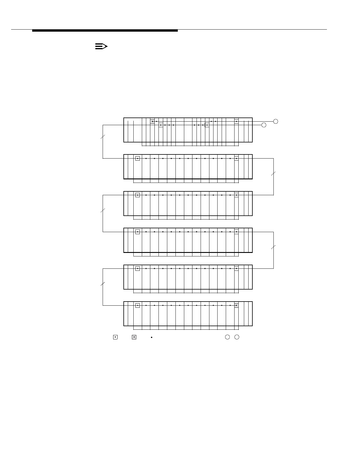
Lucent Technologies — Proprietary
See notice on first page
11-10 401-660-100 Issue 11 August 2000
Cell Site Hardware Functions and Interconnections
NOTE:
All TDM bus inter-shelf and inter-frame bus cables should be installed with
the pin 1 edge upward. The pin 1 edge is denoted by a red colored stripe.
An upside-down TDM bus cable can reduce the effective signal ground
between shelves and frames and distort the TDMSYNC1 signal, which
provides a reference signal used to lock the T1/E1 span to the TDM bus.
Figure 11-3. Physical View of TDM Buses (Sheet 1 of 3)
01 3456789101112131415
08 0902 03 04 05 06 07
P
C
U
R
C
U
12
V
P
C
U
5
V
C
A
T
2
00 01 0A 0B 0C
R
C
U
R
C
U
R
C
U
R
C
U
R
C
U
R
C
U
R
C
U
R
C
U
R
C
U
R
C
U
R
C
U
B
B
N
2
1617
01 3456789101112131415
18 1912 13 14 15 16 17
P
C
U
R
C
U
12
V
P
C
U
5
V
C
A
T
2
10 11 1A 1B 1C
R
C
U
R
C
U
R
C
U
R
C
U
R
C
U
R
C
U
R
C
U
R
C
U
R
C
U
R
C
U
R
C
U
B
B
N
2
1617
01 3456789 10 111213
0F2E 3E 4E 5E 6E 7E
P
C
U
R
C
U
12
V
P
C
U
5
V
D
S
1
2
0E 1E 1F 2F
R
C
U
R
C
U
R
C
U
R
C
U
R
C
U
R
T
U
R
C
U
R
C
U
B
B
N
2
B
B
N
1
B
B
N
1
1415
01 3456789101112131415
28 2922 23 24 25 26 27
P
C
U
R
C
U
12
V
P
C
U
5
V
D
S
1
2
20 21 2A 2B 2C
R
C
U
R
C
U
R
C
U
R
C
U
R
C
U
R
C
U
R
C
U
R
C
U
R
C
U
R
C
U
R
C
U
B
B
N
2
B
B
N
1
B
B
N
1
1617
01 3456789101112131415
38 3932 33 34 35 36 37
P
C
U
R
C
U
12
V
P
C
U
5
V
D
S
1
2
30 31 3A 3B 3C
R
C
U
R
C
U
R
C
U
R
C
U
R
C
U
R
C
U
R
C
U
R
C
U
R
C
U
R
C
U
R
C
U
B
B
N
2
B
B
N
1
B
B
N
1
1617
0 1 3456789 10 111213141516171819 20 21 22
5D6D7D0D1D5D 4D3D2D1D0D 4D
P
C
U
A
F
I
N
C
I
5
V1
G
R
W
T
H
G
R
W
T
H
G
R
W
T
H
N
C
I
0
C
P
I
M
E
M
C
P
U
P
C
U
A
F
I
N
C
I5
V
1
G
R
W
T
H
G
R
W
T
H
G
R
W
T
H
N
C
I
0
C
P
I
M
E
M
C
P
U
D
S
1
RCC 1RCC 0
2
G
R
W
T
H
G
R
W
T
H
7D6D 2D3D 7F
KEY: = AYD4 = AYD3
FRONT VIEW OF PRIMARY RCF—RCF0
SLOT ADDR
RCC
SHELF 0
RCU
SHELF 1
RCU
SHELF 2
RTU
SHELF 3
RCU
SHELF 4
RCU
SHELF 5
SLOT NUM
TDM0
22
W301
22
W302
TDM0
B
B
M
1
/
B
B
N
1
B
B
M
1
/
B
B
N
1
B
B
M
1
/
B
B
N
1
B
B
M
1
/
B
B
N
1
22
W300
22
W304
TDM0
22
W303
BA
TDM0
TDM1
TDM0
ABTO/ FROM SHEET 2= TDM-BUS SLOT CONNECTION
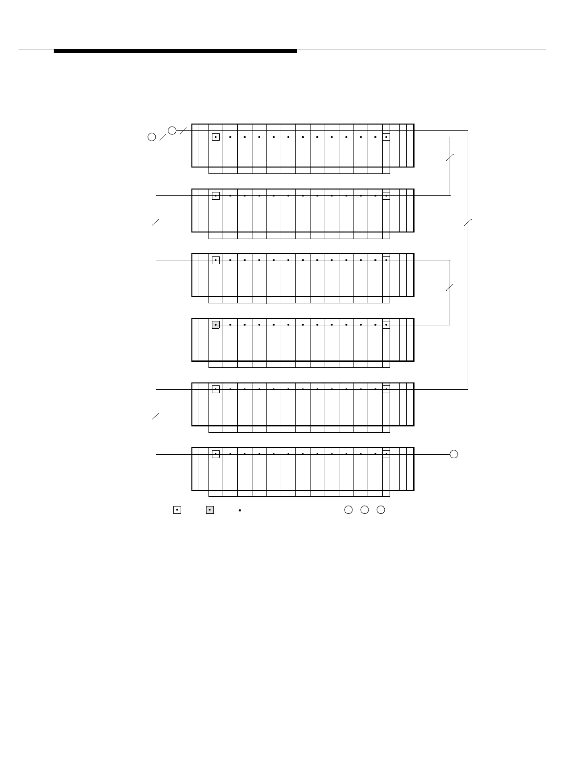
Lucent Technologies — Proprietary
See notice on first page
401-660-100 Issue 11 August 2000 11-11
Cell Site Hardware Functions and Interconnections
.
Figure 11-4. Physical View of TDM Buses (Sheet 2 of 3)
TO/ FROM SHEET 1/ 3
0 1 3 4 5 6 7 8 9 10 11 12 13 14 15
78 7972 73 74 75 76 77
P
C
U
R
C
U
12
V
P
C
U
5
V
2
70 71 7A 7B 7C
R
C
U
R
C
U
R
C
U
R
C
U
R
C
U
R
C
U
R
C
U
R
C
U
R
C
U
R
C
U
R
C
U
B
B
N
2
B
B
N
1
B
B
N
1
1617
0 1 3 4 5 6 7 8 9 10 11 12 13 14 15
58 5952 53 54 55 56 57
P
C
U
R
C
U
12
V
P
C
U
5
V
D
S
1
2
50 51 5A 5B 5C
R
C
U
R
C
U
R
C
U
R
C
U
R
C
U
R
C
U
R
C
U
R
C
U
R
C
U
R
C
U
R
C
U
B
B
N
2
B
B
N
1
B
B
N
1
1617
0 1 3 4 5 6 7 8 9 10 11 12 13 14 15
68 6962 63 64 65 66 67
P
C
U
R
C
U
12
V
P
C
U
5
V
2
60 61 6A 6B 6C
R
C
U
R
C
U
R
C
U
R
C
U
R
C
U
R
C
U
R
C
U
R
C
U
R
C
U
R
C
U
R
C
U
B
B
N
2
B
B
N
1
B
B
N
1
1617
0 1 3 4 5 6 7 8 9 10 11 12 13 14 15
48 4942 43 44 45 46 47
P
C
U
R
C
U
12
V
P
C
U
5
V
D
S
1
2
40 41 4A 4B 4C
R
C
U
R
C
U
R
C
U
R
C
U
R
C
U
R
C
U
R
C
U
R
C
U
R
C
U
R
C
U
R
C
U
B
B
N
2
B
B
N
1
B
B
N
1
1617
0 1 3 4 5 6 7 8 9 10 11 12 13 14 15
08 0902 03 04 05 06 07
P
C
U
R
C
U
12
V
P
C
U
5
V
C
A
T
2
00 01 0A 0B 0C
R
C
U
R
C
U
R
C
U
R
C
U
R
C
U
R
C
U
R
C
U
R
C
U
R
C
U
R
C
U
R
C
U
B
B
N
2
B
B
N
1
B
B
N
1
1617
01 3 45678910 11 12 13 14 15
18 1912 13 14 15 16 17
P
C
U
R
C
U
12
V
P
C
U
5
V
C
A
T
2
10 11 1A 1B 1C
R
C
U
R
C
U
R
C
U
R
C
U
R
C
U
R
C
U
R
C
U
R
C
U
R
C
U
R
C
U
R
C
U
B
B
N
2
B
B
N
1
B
B
N
1
1617
KEY: = AYD4 = AYD3
FRONT VIEW OF FIRST GROWTH RCF—RCF1
RCU
SHELF 0
RCU
SHELF 1
RCU
SHELF 2
RCU
SHELF 3
RCU
SHELF 4
RCU
SHELF 5
SLOT NUM
22
W307
22
W306
22
W305
TDM1
22
W309
SLOT ADDR
TDM0
TDM0
TDM1
22
W310
A
B
B CA
C
TDM1
22 22
= TDM-BUS SLOT CONNECTION
W311
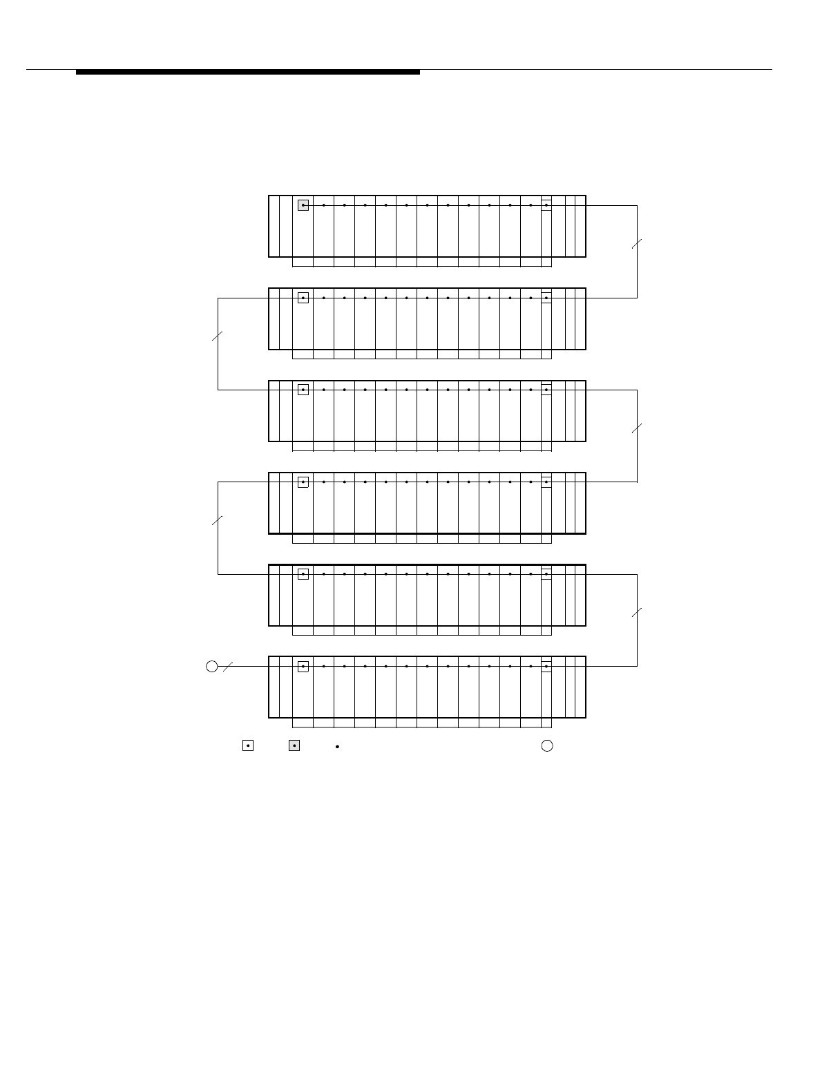
Lucent Technologies — Proprietary
See notice on first page
11-12 401-660-100 Issue 11 August 2000
Cell Site Hardware Functions and Interconnections
Figure 11-5. Physical View of TDM Buses (Sheet 3 of 3)
If the radio frame set consists of only the primary RCF, AYD3 termination
paddleboards (instead of AYD4 paddleboards) are installed on the wiring side of
RCF0 shelf 0, slots 15 and 21.
01 3456789101112131415
58 5952 53 54 55 56 57
P
C
U
R
C
U
12
V
P
C
U
5
V
2
50 51 5A 5B 5C
R
C
U
R
C
U
R
C
U
R
C
U
R
C
U
R
C
U
R
C
U
R
C
U
R
C
U
R
C
U
R
C
U
B
B
N
2
B
B
N
1
B
B
N
1
1617
01 3 45678910 11 12 13 14 15
38 3932 33 34 35 36 37
P
C
U
R
C
U
12
V
P
C
U
5
V
2
30 31 3A 2B 3C
R
C
U
R
C
U
R
C
U
R
C
U
R
C
U
R
C
U
R
C
U
R
C
U
R
C
U
R
C
U
R
C
U
B
B
N
2
B
B
N
1
B
B
N
1
1617
01 3456789101112131415
48 4942 43 44 45 46 47
P
C
U
R
C
U
12
V
P
C
U
5
V
D
S
1
2
40 41 4A 4B 4C
R
C
U
R
C
U
R
C
U
R
C
U
R
C
U
R
C
U
R
C
U
R
C
U
R
C
U
R
C
U
R
C
U
B
B
N
2
B
B
N
1
B
B
N
1
1617
01 3456789101112131415
28 2922 23 24 25 26 27
P
C
U
R
C
U
12
V
P
C
U
5
V
D
S
1
2
20 21 2A 2B 2C
R
C
U
R
C
U
R
C
U
R
C
U
R
C
U
R
C
U
R
C
U
R
C
U
R
C
U
R
C
U
R
C
U
B
B
N
2
B
B
N
1
B
B
N
1
1617
01 3456789101112131415
68 6962 63 64 65 66 67
P
C
U
R
C
U
12
V
P
C
U
5
V
D
S
1
2
60 61 6A 6B 6C
R
C
U
R
C
U
R
C
U
R
C
U
R
C
U
R
C
U
R
C
U
R
C
U
R
C
U
R
C
U
R
C
U
B
B
N
2
B
B
N
1
B
B
N
1
1617
01 3456789101112131415
78 7972 73 74 75 76 77
P
C
U
R
C
U
12
V
P
C
U
5
V
2
70 71 7A 7B 7C
R
C
U
R
C
U
R
C
U
R
C
U
R
C
U
R
C
U
R
C
U
R
C
U
R
C
U
R
C
U
R
C
U
B
B
N
2
B
B
N
1
B
B
N
1
1617
KEY: = AYD4 = AYD3
FRONT VIEW OF SECOND GROWTH RCF—RCF2
RCU
SHELF 0
RCU
SHELF 1
RCU
SHELF 2
RCU
SHELF 3
RCU
SHELF 4
RCU
SHELF 5
SLOT NUM
22
W309
TDM1
SLOT ADDR
22
W307
22
W305
22
W306
22
W308
TDM1
TDM1
TDM1
TDM1
CTO/ FROM SHEET 2
C22
= TDM-BUS SLOT CONNECTION
W312

Lucent Technologies — Proprietary
See notice on first page
401-660-100 Issue 11 August 2000 11-13
Cell Site Hardware Functions and Interconnections
If the radio frame set consists of only the primary RCF and a growth RCF and
assuming that shelf 4 and/or shelf 5 of RCF1 is populated with radio equipment,
an AYD3 termination paddleboard is installed on the wiring side of RCF1 shelf 5,
slot 14. In addition, to generate clock signals for TDM1, redundant CAT units are
installed in RCF1 shelf 4, slot 14, and RCF1 shelf 5, slot 14.
Each controller contains the following set of plug-in units:
■One CPU - The core processor (CPU) unit is a 32-bit Motorola MC68020
processing element.
■One MEM - The 8-megabyte memory (MEM) unit provides the volatile main
memory resource for the CPU.
Applications in Release 9.0 and later require 8-megabytes of memory (as
opposed to 4-megabytes of memory). The 8-megabytes of memory must
be realized by installing one 8-megabyte TN1710 memory unit in RCC0
and one in RCC1. (A memory board has no pin connections to the TDM
bus.)
■One AFI - The alarms and FITS* interface (AFI) unit monitors alarm
sensors and reports adverse conditions to the CPU.
■One or Two CPIs - The communications processor interface (CPI) unit
provides BX.25 communication between the CPU and the ECP. One CPI is
required for TDM0, and one CPI is optional for TDM1.
■One or Two NCIs - The network control interface (NCI) unit provides the
communication interface between the CPU on the system bus and the
TDM-bus client units on the TDM buses. One NCI is required for each TDM
bus.
The TDM buses are always installed "red stripe up."
* FITS, for Factory Installation and Test System, is a Lucent Technologies test set that can connect to a special
connector accessible through the faceplate of the AFI. At initial frame installation, FITS is used to download Cell
Site translations and initiate diagnostic tests.

Lucent Technologies — Proprietary
See notice on first page
11-14 401-660-100 Issue 11 August 2000
Cell Site Hardware Functions and Interconnections
Data Link and Voice
Path Connections
All data link and voice path connections (See Figure 11-6) between the MSC and
its associated Cell Sites are based on the connection topology specified in the
translations (system-configuration parameters). The Cell Site radios are
connected to their appropriate DS1s or DFIs and T1 trunks (64-kbit/s channels or
DS0s) in accordance with the translations.
Cell Site translations can be set or changed from the ECP or OMP; initially, they
are maintained in the ECP’s application data bases and then downloaded to the
Cell Site RCC. Refer to the Data Base Update Manual (401-610-036) for a
complete listing of Cell Site translations.
The figure shows a data link connection path between the MSC and a Cell Site
RCC:
CDN ‹ CSN ‹ DFI* ‹ TSIU ‹ DFI ‹ FIF ‹ DS1 ‹ CPI ‹ CPU
A Cell Site data link is a static (dedicated) connection path from end to end. All
hardware, T1 trunks, and TDM bus timeslots in the path are assigned statically
(“nailed up”) in accordance with the translations.
The figure also shows a digital-voice connection path between the PSTN and a
Cell Site radio:
PSTN ‹ DFI ‹ TSIU ‹ DFI ‹ FIF ‹ DS1 ‹ RCU
A digital-voice connection path is static except for the connection between the
PSTN and the Cell Site T1 trunk (that is, the connection through the DCS). That
connection is set up and torn down dynamically by the call processing and data
base node (CDN); it is NOT specified in the translations. The CDN receives a call
setup message from the PSTN or Cell Site via a DCS or Cell Site data link. The
CDN decides how to complete the call and then sends the appropriate messages
to the DCS and the targeted Cell Site to set up the call.
T1/E1
Communications The digital-voice and signaling communications between the MSC and the RCC at
the Cell Site are based on a T1/DS1 or E1/CEPT† line interface. The T1 line
interface is the lowest level in the hierarchy of the North American T-carrier digital
transmission facility.
* The DFI at the switch is physically different but functionally equivalent to the DFI at the Cell Site.
†CEPT stands for Conference of European Postal and Telecommunications Administrations. CEPT, CEPT-1, and
E1 are equivalent terms.
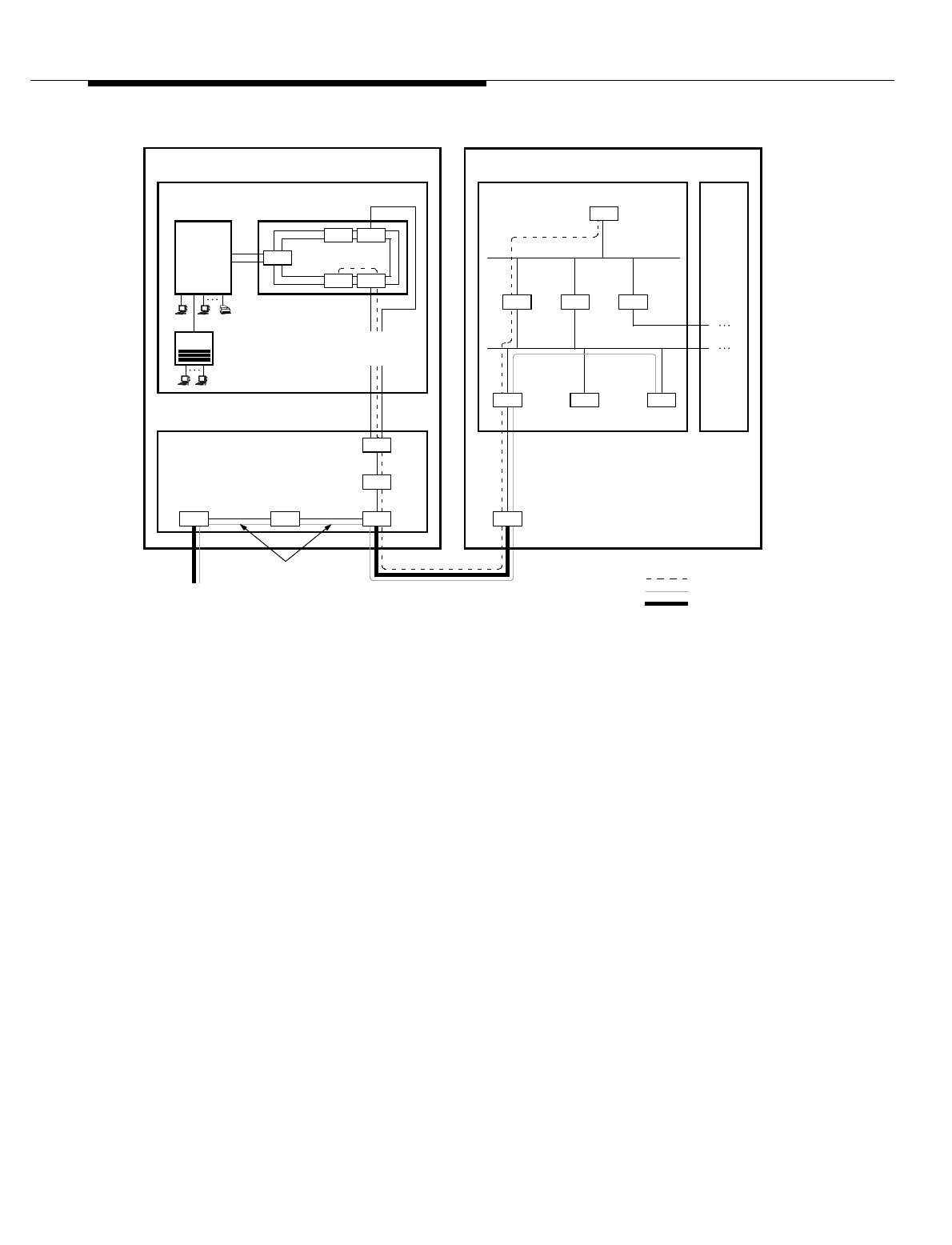
Lucent Technologies — Proprietary
See notice on first page
401-660-100 Issue 11 August 2000 11-15
Cell Site Hardware Functions and Interconnections
Figure 11-6. Data Link and Voice Paths—Example
The DS1 and DFI hardware units are the carrier line interface circuits at the Cell
Site. The DS1 can terminate one T1 line. The DFI can terminate two T1 lines or
two E1 lines, although only one termination is currently supported. That is, of the
two line interface ports on the DFI—port 0 and port 1, only port 0 is currently used
to terminate a carrier line.
SERIES II Cell Site
Voice
Data Link
T1 Lines
System Bus
CPI
TDM1
RCF0
RCF1, 2
TDM0
RCU
RPCN
5ESS®-2000 Switch DCS
ECP CNI/ IMS
OMP
CDN CSN
To/From
PSTN
ECP Complex
DRU
NCI
0
NCI
1
CPU
DFI
CSN
DFIDFI
Cell Site
DATA LINKS
(BX.25)
MSC
FIF
Dynamically
Assigned Path
DEFINITIONS:
CDN Call processing and Data base Node (Cabinet)
CNI Common Network Interface
CPI Communications Processor Interface (Board)
CPU Core Processor (Board)
CSN Cell Site Node (Cabinet)
DCS Digital Cellular Switch
DFI Digital Facilities Interface (Board)
DRU Digital Radio Unit (Board—TDMA Radio)
ECP Executive Cellular Processor
FIF Facilities Interface Frame (Cabinet)
IMS Interprocess Message Switch
MSC Mobile Switching Center
NCI Network Control Interface (Board)
OMP Operations and Management Platform
PSTN Public Switched Telephone Network
RCF Radio Channel Frame
RCU Radio Channel Unit (Board—AMPS Radio)
RPCN Ring Peripheral Controller Node (Cabinet)
SM Switching Module (Cabinet)
CDN
DFI
TSIU
TSIU

Lucent Technologies — Proprietary
See notice on first page
11-16 401-660-100 Issue 11 August 2000
Cell Site Hardware Functions and Interconnections
A Cell Site may connect to T1 lines or E1 lines but not a mixture of both. The DS1
and DFI can support the all-T1 Cell Site configuration. Only DFIs can support the
all-E1 Cell Site configuration.
T1 Line Interface
As shown in Figure 11-7, a T1/DS1 frame consists of twenty-four 8-bit timeslots,
or channels, plus one F bit (for detection of frame boundaries and the transport of
additional information), resulting in a 193-bit frame. The 193-bit frame, which is
repeated every 125 ms—8000 times per second, yields a line rate of 1544 kbit/s.
Each channel, referred to as a DS0, operates at a 64-kbit/s rate.
A T1 line is a balanced, full-duplex digital transmission line: one twisted pair to
transmit data and one twisted pair to receive data. It must be terminated at both
ends in its characteristic impedance, that is, 120 ohms. A T1 line can
accommodate 24 digital-voice communication channels or a combination of
digital-voice and signaling channels.
E1 Line Interface
As shown in Figure 11-8, an E1/CEPT frame consists of thirty-two 8-bit timeslots,
or channels, of which one channel, timeslot 0 (TS0), is reserved for framing and
alarm information. The 256-bit frame, which is repeated every 125 ms—8000
times per second, yields a line rate of 2048 kbit/s. Each channel operates at a 64-
kbit/s rate.
An E1 line is a balanced or unbalanced, full-duplex digital transmission line: one
twisted pair or coaxial cable to transmit data and one twisted pair or coaxial cable
to receive data. It must be terminated at both ends in its characteristic impedance,
that is, 120 ohms for twisted pair and 75 ohms for coaxial cable. An E1 line can
accommodate 31 digital-voice communication channels or a combination of
digital-voice and signaling channels.

Lucent Technologies — Proprietary
See notice on first page
401-660-100 Issue 11 August 2000 11-17
Cell Site Hardware Functions and Interconnections
Line Interface Connections at the Cell
The T1 line interface at the cell is 120-ohm twisted pair. The E1 line interface at
the cell is optionally configurable for 120-ohm twisted pair or 75-ohm coaxial
cable, but not both.
The channel service units (CSUs) in the FIF provide the electrical interface
between the T1 lines and the DS1s/DFIs in the RCF. Two 14-pin, D-type female
connectors provide the 120-ohm twisted-pair connector interface at the primary or
growth RCF.
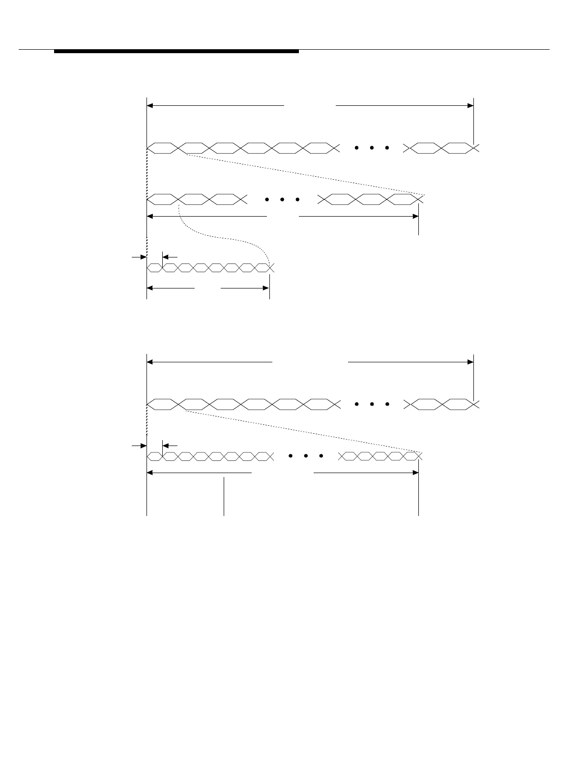
Lucent Technologies — Proprietary
See notice on first page
11-18 401-660-100 Issue 11 August 2000
Cell Site Hardware Functions and Interconnections
Figure 11-7. T1/DS1 Transmission Format and RCF TDM Bus Transmission
Format
FR0 FR1 FR2 FR3 FR4 FR5 FR7998 FR7999
CH1 CH2 CH3 FR3 CH22 CH23 CH24
01234567
FRAMES
TIMESLOTS
BITS
1
sec
(1,544,000 BITS)
5.18
µs
(8 BITS)
125
µs
(193 BITS—192 DATA BITS + 1 F BIT)
0.6477
µs
01234567
FR0 FR1 FR2 FR3 FR4 FR5 FR7998 FR7999
FRAMES
TIMESLOTS
1
sec
(2,048,000 TIMESLOTS)
125
µs
(256 TIMESLOTS)
0.5
µs
0 1 2 251 252 253 254 255
DEDICATED TO
SUPERVISION AND
CONTROL
(SEE NOTE)
DEDICATED TO
DIGITAL-VOICE/SIGNALING
TRANSPORT
NOTE:
FOR TDM0 AND TDM1, 251 TIMESLOTS ON HIGHWAY A AND HIGHWAY B (502 TIMESLOTS TOTAL)
ARE AVAILABLE FOR DIGITAL-VOICE AND SIGNALING TRANSPORT.
B. TDM BUS TRANSMISSION FORMAT
A. T1/DS1 TRANSMISSION FORMAT
(CHANNELS)
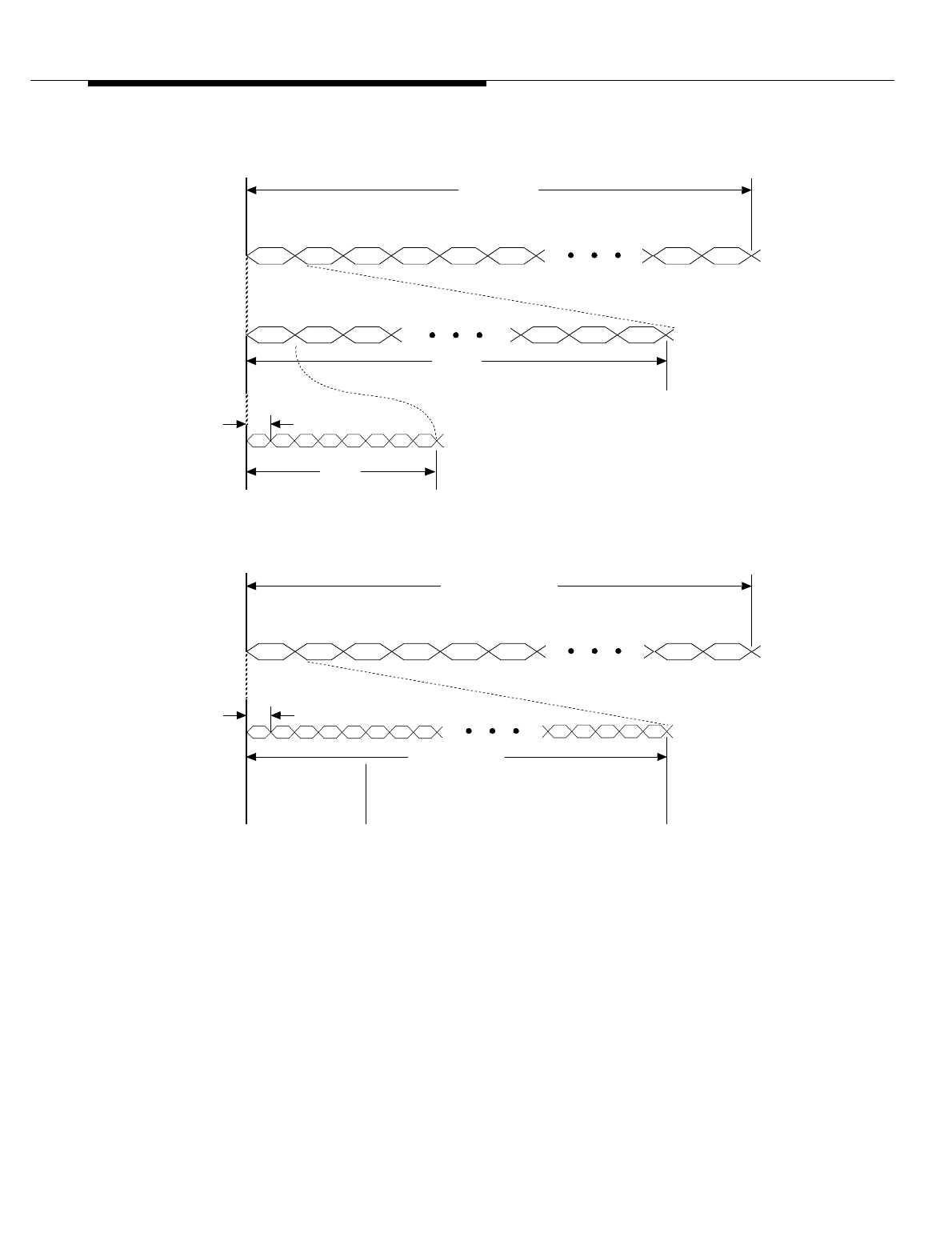
Lucent Technologies — Proprietary
See notice on first page
401-660-100 Issue 11 August 2000 11-19
Cell Site Hardware Functions and Interconnections
Figure 11-8. E1/CEPT Transmission Format and RCF TDM Bus Transmission
Format
TIMESLOTS
(CHANNELS)
FR0 FR1 FR2 FR3 FR4 FR5 FR7998 FR7999
TS0 TS1 TS2 FR3 TS29 TS30 TS31
0 1 2 3 4 5 6 7
FRAMES
BITS
1
sec
(2,048,000 BITS)
3.91
µs
(8 BITS)
125
µs
(256 BITS)
0.5
µs
0 1 2 3 4 5 6 7
FR0 FR1 FR2 FR3 FR4 FR5 FR7998 FR7999
FRAMES
TIMESLOTS
1
sec
(2,048,000 TIMESLOTS)
125
µs
(256 TIMESLOTS)
0.5
µs
0 1 2 251 252 253 254 255
DEDICATED TO
SUPERVISION AND
CONTROL
(SEE NOTE)
DEDICATED TO
DIGITAL-VOICE/SIGNALING
TRANSPORT
NOTE:
FOR TDM0 AND TDM1, 251 TIMESLOTS ON HIGHWAY A AND HIGHWAY B (502 TIMESLOTS TOTAL)
ARE AVAILABLE FOR DIGITAL-VOICE AND SIGNALING TRANSPORT.
B. TDM BUS TRANSMISSION FORMAT
A. E1/CEPT TRANSMISSION FORMAT

Lucent Technologies — Proprietary
See notice on first page
11-20 401-660-100 Issue 11 August 2000
Cell Site Hardware Functions and Interconnections
Customer-provided network termination units (NTUs)* provide the electrical
interface between the E1 lines and the DFIs in the RCF. The same two 14-pin, D-
type receptacle described above provide the 120-ohm twisted-pair connector
interface at the primary or growth RCF. An additional piece of equipment, referred
to as a balun (for balanced/unbalanced), is needed to accommodate the 75-ohm
coaxial-cable interface. A balun is an impedance-matching device used to connect
balanced twisted-pair cabling with unbalanced coaxial cable. Coaxial cables from
the NTU connect to BNC connectors on the balun, and twisted-pair cabling from
the balun connects to the two 14-pin connectors on the primary or growth RCF.
* To realize the NTU function, Lucent Technologies is currently testing an E-SMART® plug-in card developed by
Kentrox Industries. The E-SMART card would replace the T-SMART® card in the T-SMART CSU. (The T-SMART
CSU is one of two types of CSUs that may be installed in the FIF.) More information on this feature will be supplied
when it becomes available.

Lucent Technologies — Proprietary
See notice on first page
401-660-100 Issue 11 August 2000 11-21
Cell Site Hardware Functions and Interconnections
Data Link Configurations
One BX.25 data link, or signaling channel, is required between the RCC and the
ECP; two data links are needed to achieve increased reliability. The latter is best
accommodated via two carrier lines connected to two separate DS1s/DFIs, with
one BX.25 data link in each line. This arrangement ensures that no single point
failure will reduce service capability by more than 50 percent.
Data link configurations are established using the ECP DNLD: CELL a,DLOPTS
command. This command is used to establish any one of the following data link
configurations:
One DS1/DFI Unit
and One Data Link The DS1/DFI is in shelf 3, slot 12, of the primary RCF (logical unit DS1 0 as seen
at the ECP); the data link is carried in channel 24 of the attached carrier line.
One DS1/DFI Unit
and Two Data
Links
The DS1/DFI is in shelf 3, slot 12, of the primary RCF (DS1 0 as seen at the
ECP); the primary data link (DL 0) is carried in channel 24 of the attached carrier
line, and the secondary data link (DL 1) is carried in channel 13 of the attached
carrier line.
Two DS1/DFI
Units and Two
Data Links
One DS1/DFI is in shelf 3, slot 12, of the primary RCF (DS1 0 as seen at the
ECP), and one is in shelf 4, slot 14, of the primary RCF (DS1 1 as seen at the
ECP); DL 0 is carried in channel 24 of the carrier line attached to DS1 0; DL 1 is
carried in channel 24 of the carrier line attached to DS1 1.
In the current RC/V implementation, the physical unit mappings for logical units
DS1 0 and DS1 1 are fixed (as stated above) and cannot be changed by the user.
For a Cell Site configured with two data links, both data links are active. DL 0
carries call-processing messages, and DL 1 carries maintenance and locate
request messages. If one data link fails or is placed out-of-service, the other data
link must carry all of the message traffic between the RCC and the ECP; call-
processing messages have priority over maintenance and locate request
messages.
Remote Data Link
Reconfiguration Release 4.3 supports two ways to update data link parameters: by Factory
Installation Test System (FITS) and by cell data links (that is, from the Mobile
Switching Center (MSC)). While changing data link parameters from the MSC, the
cell remains in service. However, at least one Core Processor Unit (CPU) must
have the correct current data link options to keep the Cell Site in service. The new
data link parameters are downloaded to the inactive (mate) CPU. A Radio Control
Complex (RCC), that is, Cell Site Controller side switch is then made, and the
parameters are copied from the new active, updated CPU to the new mate CPU.

Lucent Technologies — Proprietary
See notice on first page
11-22 401-660-100 Issue 11 August 2000
Cell Site Hardware Functions and Interconnections
External Interfaces to the Series II Cell
Site
Voice Trunks from
the Digital
Cellular Switch
(DCS)
Cell data links from the Interprocess Message Switch (IMS) ring are connected to
the TDM buses by integrated Digital Cross-Connect (DSX-1) interfaces. Data links
from the Mobile Switching Center (MSC) are connected to TDM bus 0.
The TDM buses are always installed "red stripe up."
The TDM buses provide the paths for control and data transfer within the RFS.
Within the RFS there may be up to 200 RCUs (195 can be used for voice), 1 RTU,
14 Digital Service 1 (DS1) or Digital Facilities Interface (DFI) boards, 4 Clock And
Tone (CAT) boards, and the number of RF switch modules, transmit combiners,
receive dividers, and power supply boards required to handle the RFS
configuration used.
Time Division
Multiplexed Buses All external interfaces (that is, T1 or E1 lines from the MSC) are connected to the
RCF TDM buses via the DS1/DFI interfaces. (Data links from the MSC are
connected to TDM0 via DS1 0 and DS1 1). The TDM buses provide the paths for
control and data transfer within the primary RCF and any attached growth RCF(s).
The TDM buses are always installed "red stripe up."
TDM Bus Operation
The TDM buses, TDM0 and TDM1, are independently synchronized to individual
carrier lines connected to the cell; those lines are specified by Cell Site system
software. The DS1/DFI serving a synchronization line continually extracts a frame-
sync signal (8 kHz) from the carrier line and passes it to the active CAT unit. Using
the 8-kHz signal as the sync reference, the active CAT generates two system
clocks for the TDM bus: a 2048-kHz timeslot clock and an 8-kHz framing clock.
Each TDM bus operates at 2048 kHz with a frame rate of 8 kHz.
A TDM bus consists of two 8-bit highways (highway A and highway B); each
highway provides 256 timeslots. (Each highway requires eight wires and carries
eight bits per timeslot.) For both TDM0 and TDM1, the first five timeslots on
highway A and highway B—timeslots 0 through 4—are dedicated for control, and
the rest are used to carry user information. At any given time, only one of the
highways (highway A or highway B) is actively used to carry control information.
Timeslots 0 through 4 are referred to as the TDM bus control channel.
The TDM buses are always installed "red stripe up."
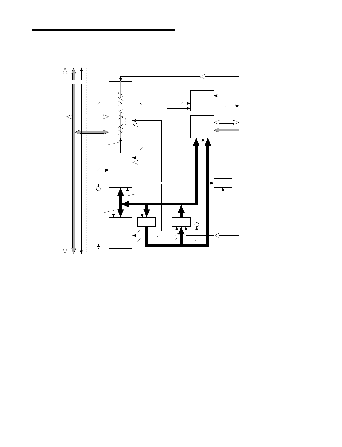
Lucent Technologies — Proprietary
See notice on first page
401-660-100 Issue 11 August 2000 11-23
Cell Site Hardware Functions and Interconnections
Figure 11-9. TDM-Bus Interface Circuitry for the NCI—TDM Bus Archangel
The updating of firmware (software stored in updatable non-volatile memory—
NVM) to TDM-bus client units is accomplished through the TDM bus, specifically,
through the TDM bus control channel. TDM-bus client units having updatable non-
volatile memory are the RCU, SBRCU, RTU, DRU, EDRU, TRTU, CCC, BIU, SCT,
and CRTUi.
TDM buses are always installed "red stripe up."
RED LED
(FAILURE)
BUS
TRANSCEIVERS
DUAL-PORT
RAM
(8-Bit Micro-
Processor)
SAKI
(Bus Sanity
And Control
Interface)
ADDRESS
LATCH EPROM
(BOOT)
TDM CLOCKS
6
2
ADDR (15)
ADDR/ DATA (8)
TO/ FROM
SYSTEM
BUS
ADDR (8)
TDM CLOCK AND CONTROL BUS.
THE 8-BIT MICROPROCESSOR (ARCHANGEL) CONTROLS WHICH TDM BUS (A OR B) CONNECTS TO THE SAKI.
6
NOTES:
1.
2.
ANA
EA
(MEMORY)
CIRCUITS
ADDR
LATCH
ENABLE
CLOCK
MONITOR/
CONTROL
ADDR (11)
ON NCI
2
3
6
(NOTE 2)
2
ADDRDATA
DATA (8)
DATA (8)
RESET
TX/ RX
Control
(Hardwired
Slot ADDR)
7
TDM BUS INTErfACE
TDM0/ 1 BUS
AB(NOTE 1)
TDMCKFAIL
TDMCKSEL
A
(+5 VDC
(ARCHANGEL
MODE)
FROM
SIDE ACTIVE
2
ADDR (10)
DATA (16)
3
A
CLK SRC SEL
ARCHANGEL

Lucent Technologies — Proprietary
See notice on first page
11-24 401-660-100 Issue 11 August 2000
Cell Site Hardware Functions and Interconnections
The CPU and CPI also have updatable non-volatile memory; the updating of CPU
or CPI firmware is accomplished through the system bus.
For the AMPS and TDMA access technologies, one full-duplex timeslot on the
TDM bus, that is, one timeslot for transmission and one for reception, can carry
one digital-voice channel. (The TDM bus interface for the RCU or SBRCU is a
single full-duplex timeslot, and the TDM bus interface for the DRU or EDRU is
three full-duplex timeslots.) For the CDMA access technology, four full-duplex
timeslots on the TDM bus, called a packet pipe, can carry up to 14 digital-voice
channels* for 8-kbit/s voice encoders (vocoders). (The TDM bus interface for the
CCC is a single packet pipe.) The timeslots are assigned statically (“nailed up”) to
the various TDM-bus client units in accordance with the Cell Site’s translations
data base.
TDM buses are always installed "red stripe up."
TDM Bus Addresses
Supervisory and control information is passed from the CPU to the various TDM-
bus clients via the TDM0 and TDM1 control channels. To control individual units
selectively on a TDM bus, a unique 7-bit address is assigned to each slot position
served by that bus. The figure identifies the 7-bit addresses—in hexadecimal
format—for the various slot positions within the primary and growth RCFs.
The pin designations for the slot address are BA0 (LSB) through BA6 (MSB). The
logic values for BA0 through BA6 are unique for each of the slot positions
connected to the TDM bus. The 7-bit address for a slot position is established by
grounding an address pin for a logic 0, and leaving an address pin unconnected
for a logic 1. The 7-pin address for a slot position is realized only when a unit is
installed in that slot position: each of the seven address pins is connected to a
pull-up resistor on the installed unit.
The backplanes for the RCU shelves are identical; therefore, each RCU shelf has
an associated 4-pole switch used to select unique logic values for the upper slot-
address bits BA4, BA5, and BA6 (See Table 11-1, and Table 11-2). The switches
are soldered to 8-pin paddleboard connectors that mount onto the wiring side
(rear side) of the backplane pinfield at slot 14 (P14).
TDM buses are always installed "red stripe up."
* In CDMA (and TDMA) terminology, a digital-voice channel is usually referred to as a traffic channel.

Lucent Technologies — Proprietary
See notice on first page
401-660-100 Issue 11 August 2000 11-25
Cell Site Hardware Functions and Interconnections
Table 11-1. Switch Settings for RCU Shelves in First Growth RCF—RCF1
Shelf Number Switch Position Settings*
1234
0Don’t Care OFF ON ON
1Don’t Care OFF ON OFF
2Don’t Care OFF OFF ON
3Don’t Care OFF OFF OFF
4Don’t Care ON ON ON
5Don’t Care ON ON OFF
* ON = Logic 0, OFF = Logic 1
Table 11-2. Switch Settings for RCU Shelves in Second Growth RCF—RCF2
Shelf Number Switch Position Settings*
1234
0Don’t Care ON OFF ON
1Don’t Care ON OFF OFF
2Don’t Care OFF ON ON
3Don’t Care OFF ON OFF
4Don’t Care OFF OFF ON
5Don’t Care OFF OFF OFF
* ON = Logic 0, OFF = Logic 1
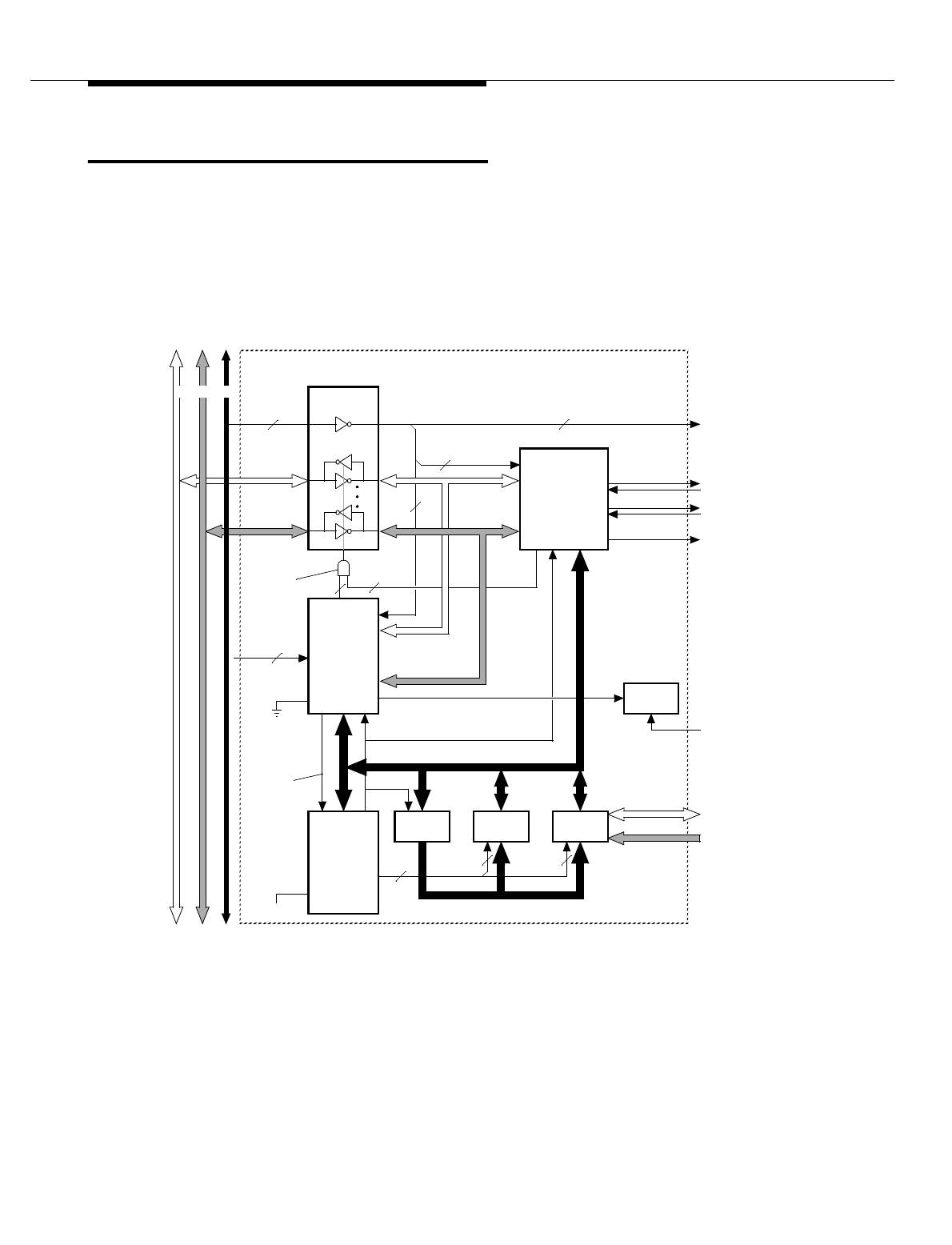
Lucent Technologies — Proprietary
See notice on first page
11-26 401-660-100 Issue 11 August 2000
Cell Site Hardware Functions and Interconnections
TDM Bus Communications: the
Archangel/Angel Concept
This section lists and briefly describes the various hardware devices that form the
TDM bus interface and perform the TDM bus communications. The NCI contains
the primary TDM bus processor, or archangel (See Figure 11-9), through which all
other TDM bus processors, or angels (See Figure 11-10), communicate. Angel
processors reside on the TDM bus client units.
Figure 11-10. TDM-Bus Interface Circuitry for the CPI—TDM Bus Angel
BUS
TRANSCEIVERS
(8-BIT MICRO-
PROCESSOR)
SAKI
(BUS SANITY
AND CONTROL
INTErfACE)
ADDRESS
LATCH
TDM CLOCKS
ADDR LATCH ENABLE
EA
ADDR (11)
ADDR/ DATA (8)
TDM CLOCK AND CONTROL BUS.
NOTE:
ANA
SRAM
ADDR (11)
3
DUAL-PORT
RAM
ADDR (8)
3
2
2
3
2
22TO/ FROM
OTHER
CIRCUITS
ON CPI
PORT 0
PORT 1
GRD
(ANGEL
MODE)
DATA (8)
DATA (8)
RESET
+5 VDC
RED LED
(FAILURE)
TX/ RX
CONTROL
(HARDWIRED
SLOT ADDR)
7
TDM BUS INTErfACE
TDM0 BUS
AB(NOTE)
2
ADDR (10)
DATA (16)
512-kHz CLK
NPE
(PARALLEL
TO SERIAL
CONVERTER,
HAS FOUR
SERIAL I/O
CHANNELS)
ANGEL

Lucent Technologies — Proprietary
See notice on first page
401-660-100 Issue 11 August 2000 11-27
Cell Site Hardware Functions and Interconnections
Angel An angel (See Figure 11-10) is an 8-bit microprocessor that serves as the TDM-
bus interface controller for a TDM bus client unit. On some units, it also serves as
the main processor for the unit.
Archangel An archangel (See Figure 11-9) is an 8-bit microprocessor on NCI0 and NCI1 that
passes messages back and forth between the CPU and the TDM bus client units
(angels). NCI0 interfaces with TDM0, and NCI1 interfaces with TDM1. The NCI is
the distribution point for all downlink messages (messages from the CPU to the
TDM bus client units) as well as the focal point for all uplink messages (messages
from the TDM bus client units to the CPU). In addition to the transfer of messages,
the archangel microprocessor monitors client-unit (angel) sanity and runs periodic
audits on the client units under control of the CPU.
A communication sequence begins when the CPU requests an activity scan of all
client units. In response to an activity scan, the client units that require uplink
message transmission transmit their slot addresses to the NCI. Next, the
archangel microprocessor grants permission to each client unit to enable uplink
message transmission. When the complete message is received, the archangel
microprocessor loads the message to the dual-port RAM for uplink transmission
to the CPU.

Lucent Technologies — Proprietary
See notice on first page
11-28 401-660-100 Issue 11 August 2000
Cell Site Hardware Functions and Interconnections
Sanity And Control Interface
The sanity and control interface (SAKI) (See Figure 11-11), a Lucent Technologies
custom device, provides a synchronous communications link between the
archangel microprocessor and the angel microprocessors via the TDM bus. The
SAKI transfers information to and from the TDM bus control channel—timeslots 0
through 4 of the TDM frame.
Each SAKI provides board-address recognition, message buffering, and bus
synchronization functions for the archangel/angel microprocessor that it supports.
The SAKI can be configured for one of two modes of operation: archangel mode
or angel mode. A logic 1 on the SAKI archangel/angel (ANA) input pin
corresponds to archangel mode; a logic 0 on ANA corresponds to angel mode.
NOTE:
TDM buses are always installed "red stripe up."
In archangel mode, the SAKI (on the NCI) transmits a slot address followed by
whatever message is to be sent to the client unit that has that slot address. It often
takes several TDM frames to transmit the complete message to the targeted unit.
In the receive direction, the SAKI reads and saves all five control channel
timeslots of every TDM frame. Messages are passed to the archangel just as they
are when the SAKI is in angel mode.
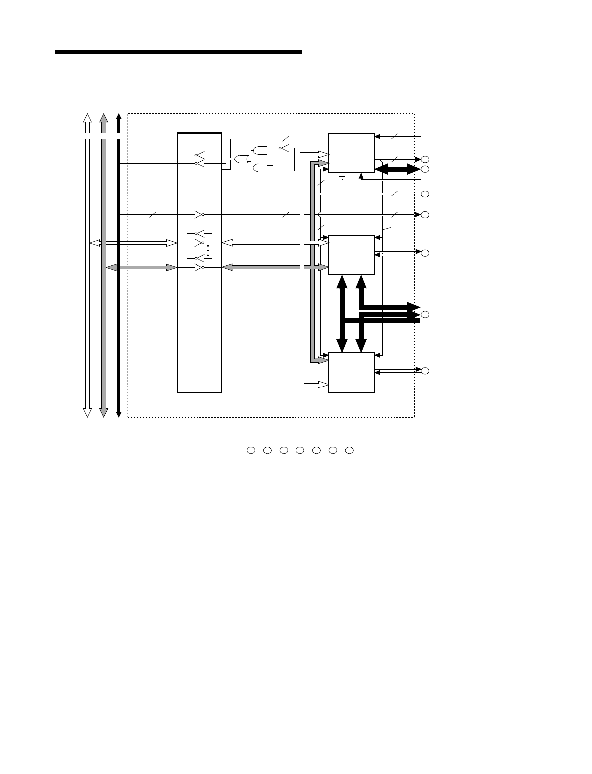
Lucent Technologies — Proprietary
See notice on first page
401-660-100 Issue 11 August 2000 11-29
Cell Site Hardware Functions and Interconnections
Figure 11-11. SAKI and SNPE Interface
In angel mode, the SAKI (on the TDM-bus client units) monitors the TDM bus
control channel and extracts and holds any information addressed to its angel
microprocessor until the angel microprocessor removes it. The SAKI also
transmits information onto the TDM bus control channel on command from its
angel microprocessor
Sanity checks between the archangel and angel microprocessor are routinely
performed through the SAKI-angel interface. The SAKI monitors the TDM bus for
sanity scans on the TDM bus control channel (directed from the archangel), and
reports any scan request to its angel microprocessor. Sanity control is handled by
C
2
(NOTE)BA
BUS
Tr a ns c ei v er s
ADDR DATA
SNPE 0
(Scotch
Network
Processing
Element 0)
SAKI
(Bus Sanity
And Control
Interface)
ANA ADDR/
DATA
TDM CLOCKS 2D
F
B
RESET
2
2
E
G
TDM CLOCK AND CONTROL BUS
NOTE:
D E F G TO/ FROM SHEET 2A B C
2
2
P/O TDM BUS INTErfACE
TDM0/1 BUS
DATA (8)
DATA (8)
TDMSYNC2
TDMSYNC1
2
DATA (8)
DATA (8)
ADDR DATA
SNPE 1
A
4
(HARDWIRED
SLOT ADDR)
7

Lucent Technologies — Proprietary
See notice on first page
11-30 401-660-100 Issue 11 August 2000
Cell Site Hardware Functions and Interconnections
a hardware timer that the angel must reset periodically. If the angel does not reset
the timer within the allotted time, the SAKI resets (disables) the angel
microprocessor, turns on the on-board red LED (indicating an error on the unit),
and reports the loss to the archangel microprocessor.

Lucent Technologies — Proprietary
See notice on first page
401-660-100 Issue 11 August 2000 11-31
Cell Site Hardware Functions and Interconnections
NPE and SNPE
The network processing element (NPE) and SCOTCH network processing
element (SNPE), both Lucent Technologies custom devices, perform timeslot
exchange between the parallel TDM bus and serial data buses called
concentration highways, that is, perform parallel-to-serial and serial-to-parallel
conversion of digital-voice data.* They communicate with the TDM bus (highway
A, highway B, or both) during timeslots 5 to 255 of the 256-slot TDM frame.
Each channel of an NPE or SNPE can be programmed by the angel
microprocessor to access two different TDM timeslots: one to carry the channel’s
received samples (uplink information) and the other to carry the channel’s
transmitted samples (downlink information). When the CPU places a channel in
loop-around mode, the channel’s receive timeslot and transmit timeslot are looped
together.
* The CPI TDM-bus interface circuitry uses the NPE device. Other units, such as the DFI and CCC, use SNPE
devices because they provide eight times the capacity of NPE devices. An SNPE has 32 serial I/O channels, and
an NPE has four serial I/O channels.

Lucent Technologies — Proprietary
See notice on first page
11-32 401-660-100 Issue 11 August 2000
Cell Site Hardware Functions and Interconnections
Synchronization of the Cell Site to the
MSC
The DS1/DFI provides an external clock source used to synchronize all digital-
voice and signaling transfers between the carrier lines and the internal TDM
buses. The TDM buses, TDM0 and TDM1, are independently synchronized to the
MSC via separate DS1/DFI units (See Figure 11-12, and Figure 11-13).
NOTE:
TDM buses are always installed "red stripe up."
Only one of two DS1s/DFIs may provide the external clock source for TDM0.
Those units are the DS1/DFI in shelf 3, slot 12, of the primary RCF (DS1 0 as
seen at the ECP) and the DS1/DFI in shelf 4, slot 14, of the primary RCF (DS1 1
as seen at the ECP).
Similarly, only one of two DS1s/DFIs may provide the external clock source for
TDM1. Those units are the first two equipped DS1s/DFIs found by Cell Site
system software residing on TDM1. There are occasions when only one DS1/DFI
is designated as an external clock source for a TDM bus.
Only one DS1 or DFI can be the synchronization reference for a TDM bus at any
given time. That unit will have a lighted green LED.
Only synchronization of TDM0 will be considered in the following discussion. The
two DS1s/DFIs that may provide the external clock source for TDM0 will be
referenced by their logical unit numbers, DS1 0 and DS1 1. All concepts applying
to TDM0 synchronization will also apply to TDM1 synchronization.
For TDM0, a valid synchronization-reference configuration is (1) a carrier line
connected to DS1 0, (2) a carrier line connected to DS1 1, or (3) for reliability, both
a carrier line connected to DS1 0 and a carrier line connected to DS1 1. In the
latter configuration, DS1 0 is the primary synchronization reference, or sync_1,
and DS1 1 is the secondary synchronization reference, or sync_2.
In the figure, logical units DS1 0 and DS1 1 are realized by the DFI; all hardware
units in the figure reside in the primary RCF. For simplicity, no TDM0 bus
connection is shown for DS1 1.
Initially, when the primary RCF comes on-line, the system attempts to select
sync_1 as the synchronization reference. If that source fails (or is not present) and
assuming that the DS1/DFI and carrier line associated with sync_2 are
operational (that is, DS1 1 is not insane and there is no alarm or only a minor,
misframe, slip, or 10e-6 error-ratio alarm on the carrier line), the system will select
sync_2 as the new synchronization reference.
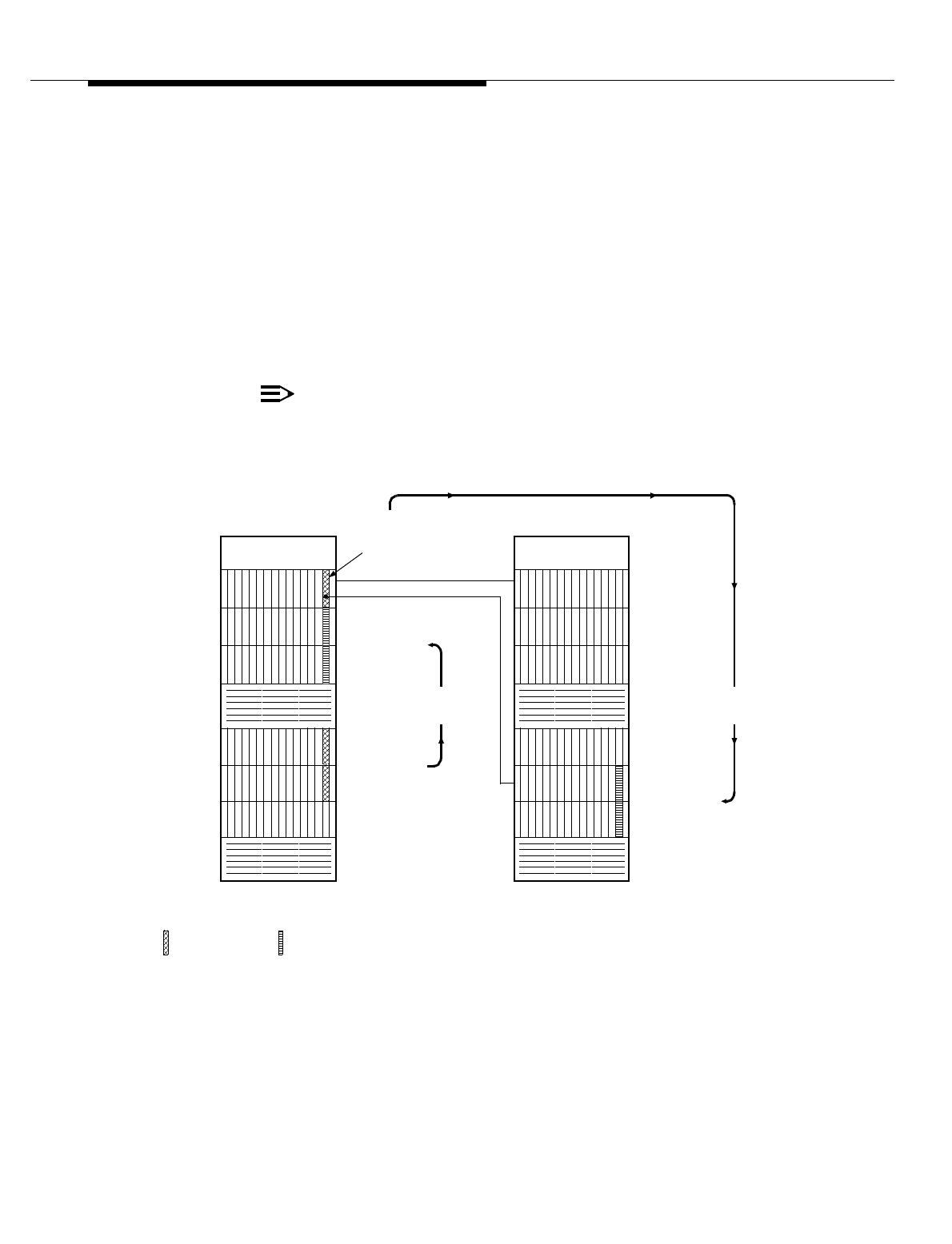
Lucent Technologies — Proprietary
See notice on first page
401-660-100 Issue 11 August 2000 11-33
Cell Site Hardware Functions and Interconnections
If neither sync_1 nor sync_2 is an acceptable synchronization reference, the
system will use an internal oscillator as the synchronization reference. That
oscillator, referred to as the local reference oscillator or just local oscillator, is
located on the CAT unit. It is a free-running oscillator running at the carrier line
rate of 2048 kHz. Since it is free running, that is, not locked (synchronized) to the
carrier lines, slips1 (which result in the repeat or loss of a frame of incoming data)
are bound to occur. For that reason, the fault preventing the use of an external
clock source should be isolated and corrected as soon as possible.
When a TDM bus is synchronized to the local reference, Cell Site system software
attempts to switch to the primary or secondary reference DS!/DFI every five
minutes. The switch will only proceed if the primary or secondary reference DS!/
DFI is now free of alarms and in the active state.
NOTE:
TDM buses are always installed "red stripe up."
Figure 11-12. Synchronization References for TDM0 and TDM1—Example
FOR TDM1
PRIMARY
SYNC REF
SYNC REF
PRIMARY &
SECONDARY
FOR TDM0
=CAT
SHELF 0
SHELF 1
FANS
SHELF 3
SHELF 4
SHELF 5
SHELF 2
AMPS/TDMA RCF0 AMPS/TDMA RCF1
TDM1
0
1
3
2
TDM0
=DS1 OR DFI
0
1
FOR TDM1
REDUNDANT
CAT UNITS
FOR TDM0
REDUNDANT
CAT UNITS
8-KHz
REF SIG 8-KHz
REF SIG

Lucent Technologies — Proprietary
See notice on first page
11-34 401-660-100 Issue 11 August 2000
Cell Site Hardware Functions and Interconnections
In the figure, the active (on-line) CPU sends a message to DS1 0 specifying that
the 8-kHz signal derived from the T1_0/ E1_0 receive bit stream be connected to
TDMSYNC1. Likewise, the active CPU sends a message to DS1 1 specifying that
the 8-kHz signal derived from the T1_0/ E1_0 receive bit stream be connected to
TDMSYNC2. The active CPU also writes the control register of the active NCI0 to
specify which of the two CATs is to supply the TDM system clocks. (The NCI uses
TDMCKSEL to activate the specified CAT.) And finally, the active CPU sends a
message to the active CAT specifying which synchronization reference is to
connect to the clock generator circuit.
NOTE:
TDM buses are always installed "red stripe up."
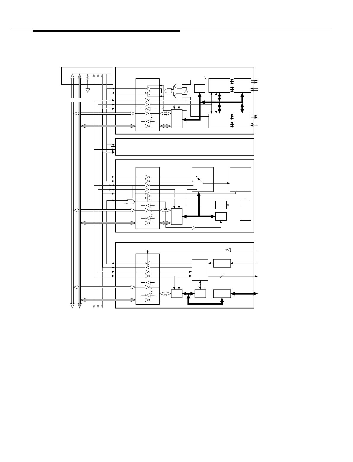
Lucent Technologies — Proprietary
See notice on first page
401-660-100 Issue 11 August 2000 11-35
Cell Site Hardware Functions and Interconnections
Figure 11-13. Synchronization of TDM0 to the MSC
For the active CAT, only TDMSYNC1, TDMSYNC2, and the 8-kHz LOC signals
are valid choices as the synchronization reference. For the standby (off-line) CAT,
only TDMFR is a valid choice as the synchronization reference; on-board
hardware forces TDMFR as the synchronization reference to keep the standby
clock generator in step with the active clock generator.
BUS
TRANSCEIVERS
P/O DS1 0 (SHELF 3, SLOT 12)
TDMSYNC1
TDMSYNC2
TDMFR
TDMCLK
TO/ FROM
T1_0/ E1_0
SAKI
LINE
INTErfACE
DEVICE 0
ANGEL
TO/ FROM
T1_1/ E1_1
8-kHz CLOCK
DERIVED FROM
T1_0/ E1_0
BUS
TRANSCEIVERS
P/O CAT 0 OR CAT 1 (SHELF 1 OR 2, SLOT 14)
TDMSYNC2
TDMSYNC1
TDMFR
TDMCLK
ANGEL
SAKI
BA4
*
NC
SYNC SOURCE
REF SELECT
LOCAL
OSC
CLOCK
GENERATOR
(PHASE LOCK
LOOP)
8-kHz REF
8-kHz LOC
÷
BY
256
(2048
kHz)
2048 kHz
8 kHz
BUS
TRANSCEIVERS
DUAL-PORT
RAM
CLOCK
MONITOR/
CONTROL
MESSAGES
P/O NCI
0
(SHELF 0, SLOT 8 OR 13)
TDMCKFAIL
TDMCKSEL
TDMCLK
SIDE ACTIVE
CLK SRC SEL
CLK FAIL (2)
TDMFR
SAKI
TO/ FROM
SYSTEM
2
BUS 0/1
P/O DS1 1 (SHELF 4, SLOT 14)
SAME AS DFI ABOVE
NC
LINE
INTErfACE
DEVICE 1
PRIMARY
ACCESS
CONTROLLER/
FRAMER 0
PRIMARY
ACCESS
CONTROLLER/
FRAMER 1
AYD3
TDM0 BUS
2
ONLINE
*
BA4
=
0 FOR CAT IN SHELF 1 BA4
=
1 FOR CAT IN SHELF 2
BA4
=
TDMCKSEL
‘
ACTIVE (ON-LINE) CAT
CONTROL
REGISTER
6
(NOT USED)
ARCH-
ANGEL

Lucent Technologies — Proprietary
See notice on first page
11-36 401-660-100 Issue 11 August 2000
Cell Site Hardware Functions and Interconnections
The signal lines called out in the figure are summarized below:
TDMCKSEL TDM clock select. Selects which of the two CAT units is to supply the TDM system
clocks. A logic 0 on TDMCKSEL selects CAT 0, while a logic 1 selects CAT 1. The
source of TDMCKSEL is the active NCI0, which sets the logic state of the signal
either (1) autonomously, if enabled by the active CPU, or (2) as directed by the
active CPU.
TDMCKFAIL TDM clock failure. When asserted (logic 1), indicates the failure of one or both of
the TDM system clocks. The source of TDMCKFAIL is the active NCI0, which
asserts the signal autonomously. (TDMCKFAIL is used to alert the attached TDM-
bus client units of a TDM bus clock failure.)
TDMCLK TDM timeslot clock (2048 kHz). One of the two TDM system clocks supplied by
the active CAT. A negative transition indicates the beginning of a TDM timeslot.
TDMFR TDM frame clock (8 kHz). One of the two TDM system clocks supplied by the
active CAT. A positive-going pulse marks the beginning of the last timeslot in a
TDM frame. (A TDM frame consists of 256 timeslots.)
TDMSYNC1 TDM bus synchronization reference 1. An 8-kHz framing signal derived from the
T1_0/ E1_0 receive bit stream, used to synchronize the TDM bus with the MSC.
This signal is sourced from DS1 0 as directed by the active CPU. TDMSYNC1
routes to both CAT units, where the active CAT uses the signal as a
synchronization reference to generate the TDM system clocks.
TDMSYNC2 TDM bus synchronization reference 2. An 8-kHz framing signal derived from the
T1_0/ E1_0 receive bit stream, used to synchronize the TDM bus with the MSC.
This signal is sourced from DS1 1 under command of the active CPU.
TDMSYNC2 routes to both CAT units, where the active CAT uses the signal as an
alternate synchronization reference to generate the TDM system clocks.
(TDMSYNC2 is an alternate signal to TDMSYNC1.)
There is another set of the same signal lines described above associated with
TDM1, NCI1, CAT 2, and CAT 3.

Lucent Technologies — Proprietary
See notice on first page
401-660-100 Issue 11 August 2000 11-37
Cell Site Hardware Functions and Interconnections
Mobile Switching Center (MSC) to
Cell Site Communications
For all Cell Releases prior to R5.1, the data and voice communications between
the Mobile Switching Center (MSC) and the Cell Site are based on a DS1 (Digital
Signal - Level 1) interface facility. It is a bipolar return-to-zero signal at a 1.544-Mb/
s rate. A DS1 signal consists of 24 DS0 (Digital Signal - Level 0) channels. The
Cell Site data communication links are capable of operating at 9.6-kb/s, 56-kb/s,
or 64-kb/s rates.
A DS1 carrier link can accommodate 24 digital voice communication channels or
a combination of digital voice and data channels. For each DS1 link, the Radio
Channel frames (RCFs) must have 1 DS1 interface circuit. One DS1 link and an
interface circuit are needed for each of the 24 voice channels. Two data links are
required between the P-RCF and the MSC for reliability. This is best
accommodated by two DS1 links, with one data channel in each link. The two DS1
interface circuits needed in this arrangement are located on shelves 3 and 4 in the
P-RCF.
All Cell Site interfaces are digital, using DS1 boards with a Digital Cross-Connect
(DSX-1) interface. When the facility is a T1 carrier, the DSX-1 interface allows
connection directly to channel service units without the need for D4 channel
banks. If analog facilities are used, D4 banks would, however, be required. The
DSX-1 interface allows up to 660 feet between the DS1 board and the
interconnecting facility.
The DSX-1 interface also allows connection directly to microwave systems or to
fiber-optic systems such as the DDM-1000. For the physical connections between
the DS1 carrier facilities and each RCF, two cable/connector assemblies are used,
one for transmit and one for receive.
The cell R5.1 Conference of European Postal and Telecommunications (CEPT)
feature provides a Cell Site that can operate in “international mode”. A Cell Site
operated in the “domestic mode” communicates via the DS1 protocol over T1
facilities; a Cell Site operated in the “international mode” communicates via the
CEPT protocol over E1 facilities. A Cell Site operating in the “international mode”
can provide 30 channels for voice traffic.
A Cell Site operated in the “domestic mode” can use either a DS1 communication
circuit pack or a Digital Facilities Interface (DFI) circuit pack. A Cell Site operated
in the “international mode” must use the DFI circuit pack.
All data and voice communications between the MSC and Cell Sites operating in
the “international mode” are based on a CEPT interface facility. This is a high
density binary three signal at a 2.048-Mb/s rate. CEPT signal consists of 31 digital
signal channels.

Lucent Technologies — Proprietary
See notice on first page
11-38 401-660-100 Issue 11 August 2000
Cell Site Hardware Functions and Interconnections
DS1, DFI, and CAT Circuit
Descriptions
This section presents circuit descriptions for the DS1, DFI, and CAT plug-in circuit
boards. The DS1 apparatus code is TN171, the DFI apparatus code is TN3500,
and the CAT apparatus code is TN170.
DS1 (TN171)
Circuit
Description
The DS1 provides the interface between the RCF TDM bus, TDM0 or TDM1, and
a T1 digital transmission line. The T1 line interface is the lowest level in the
hierarchy of the North American Tcarrier digital transmission facility, which
multiplexes twenty-four 64-kbit/s channels into a serial digital trunk (1544A kbit/s).
The DS1 architecture is based on (1) the LC1046 DS1 line interface, (2) a DS1
chip set consisting of four large-scale integration circuits, and (3) the 327DA
network processing element (NPE), all Lucent Technologies custom devices. The
DS1 chip set provides the complete interface between a DS1 line interface device
and 24 serial data channels that connect to the NPEs.
NOTE:
TDM buses are always installed "red stripe up."
DFI (TN3500)
Circuit
Description
The DFI provides the interface between the RCF TDM bus, TDM0 or TDM1, and
two T1 or E1 (CEPT-1)* digital transmission lines, although only one T1 or E1 line
interface is currently supported. The E1 line interface is the lowest level in the
hierarchy of the European E-carrier digital transmission facility, which multiplexes
thirty-two 64-kbit/s channels into a serial digital trunk (2048 kbit/s).
The DFI architecture is based on the following:
■The T7290 T1/CEPT line interface
■The T7230 primary access controller/framer (PAC) (See Figure 11-14)
■The 327HB SCOTCH network processing element (SNPE).
All of which are Lucent Technologies custom devices. Each of the two PACs, one
for each carrier line, provides the complete interface between a T1/CEPT line
interface device and a serial data bus known as the concentration highway that
connects to the SNPEs.
Both the PAC and T1/CEPT line interface devices can be configured for T1 or E1
operation.
* CEPT stands for Conference of European Postal and Telecommunications Administrations. CEPT-1 and E1 are
equivalent terms.

Lucent Technologies — Proprietary
See notice on first page
401-660-100 Issue 11 August 2000 11-39
Cell Site Hardware Functions and Interconnections
The T1/CEPT line interface device along with transformers, impedance-matching
resistors, and manually set switches provide the digital transmission line interface
(Refer to Table 11-3). The switches allow for T1 120-ohm operation or E1120-ohm
or 75-ohm operation, as defined by the SW1 through SW5 switch settings in the
table. The receive line-interface transmission format (on the line side) is alternate
mark inversion (AMI), where a 1 is represented by either a positive or negative
pulse, and a 0 is represented by a null pulse (no pulse). All pulse shapes are
controlled by the T1/CEPT line interface device according to its equalizer control
inputs, as defined by the SW6 and SW7 switch settings in the table. The receive
digital output format (on the PAC side) is dual-rail nonreturn to zero (NRZ).
To set switches SW1 through SW7, ensure that the DFI is out-of-service and then
remove the DFI from its slot location. (There is no need to remove power from the
slot location.) The switches are located at the middle (SW1-SW5) and the
faceplate end (SW6, SW7) of the circuit board. Always wear a wrist grounding
strap when handling circuit boards.
NOTE:
TDM buses are always installed "red stripe up."
The PAC provides T1 or E1 framing, alarm reporting, performance monitoring,
jitter attenuation, loopback, and independent receive and transmit framer paths.
On the line interface side, the PAC receives dual-rail data and a receive line clock
from the T1/CEPT line interface device, converts the data to a transistor-transistor
logic (TTL) format, and then transmits the data onto the concentration highway
using the TDM timeslot clock (2048 kHz). On the system side (TDM bus side), the
PAC receives TTL data from the concentration highway at the TDM timeslot clock
rate, converts the data to the dual-rail format, and then transmits the data and a
transmit line clock (phase locked to the TDM timeslot clock) to the T1/CEPT line
interface device. The PAC also derives an 8-kHz signal from the receive line clock
to serve as a possible synchronization reference for the TDM clock source.
Both the PAC and the SNPE have a dual, high-speed, serial interface for
connection to two pairs of transmit and receive serial data buses known as
concentration highway A and concentration highway B. Data may be transmitted
or received on either one of these highways. In the DFI implementation, only
concentration highway A is used for data exchange between a PAC and an SNPE.
The highway operates as a 2048-kbit/s 32-timeslot serial bus where each timeslot
is 8-bits wide.
The SNPEs provide a programmable interface between the concentration
highways and the parallel TDM bus. The SNPEs can provide a connection
between any of the timeslots on the carrier line and any of the 251 timeslots on
highway A or B of the TDM bus (TDM0 or TDM1).
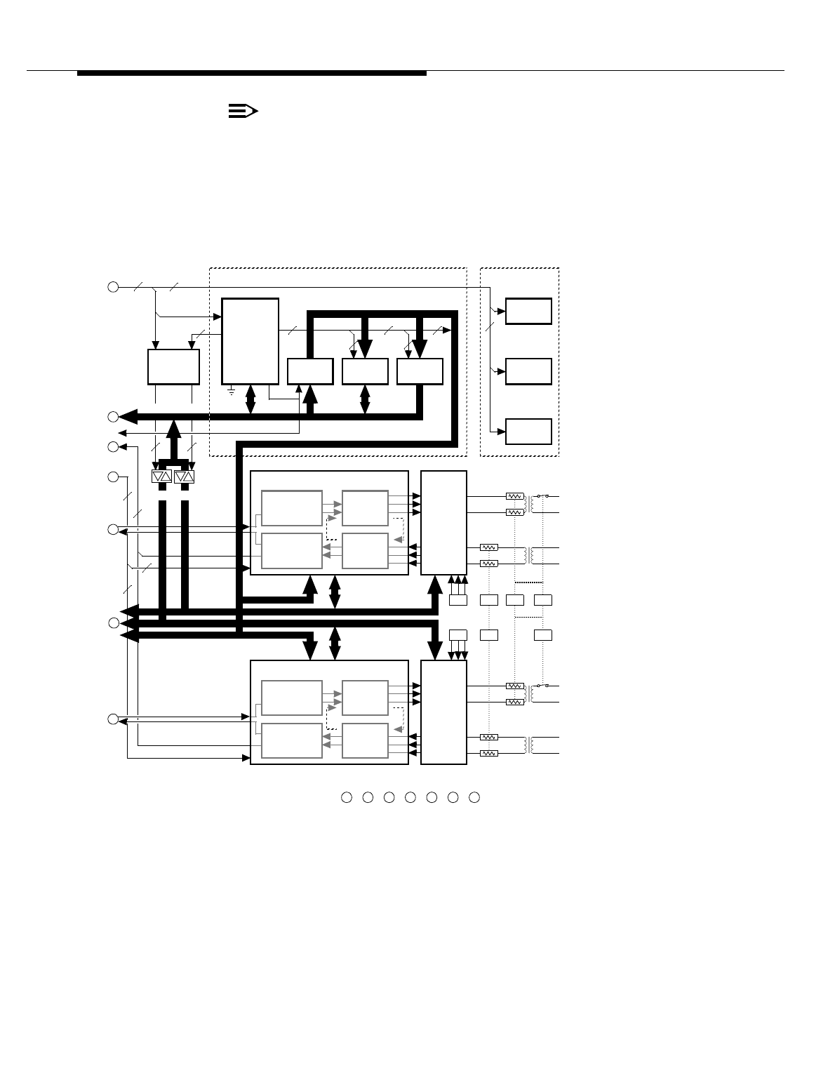
Lucent Technologies — Proprietary
See notice on first page
11-40 401-660-100 Issue 11 August 2000
Cell Site Hardware Functions and Interconnections
NOTE:
TDM buses are always installed "red stripe up."
DFI (TN1713B)
Circuit Operation Currently supplied DFI.
Figure 11-14. Primary Access Controller/Framer
(8-
Bit Micro-
Processor)
Angel
5
Grn LED
(Sync Src)
Red LED
(Failure)
Addr / Data (8)
* Primary Access Controller/ Framer
D E F GA B C
Address
Latch
SRAM
Addr (8)
8
EEPROM
7
7 2
EA
Ye l L E D
(Line Alm
)
Visual Indicators
8-kHz CLOCK
Extracter
&
Elastic Store
PAC 0*
Signaling
Inserter
Transmit
Line
Encoder
Receive
Line
Decoder
LLB
Secondary
Bus
Control
BLB
To
T1_0/ E1_0
2
From
T1_0/ E1_0
F
B
(8)(8)
2
E
8-kHz CLOCK
Extracter &
Elastic Store
PAC 1*
Signaling
Inserter
Transmit
Line
Encoder
Receive
Line
Decoder
LLB
Line
I
nterface
Device 1
BLB
To
T1_1/ E1_1
From
T1_1/ E1_1
8-KHz CLK_0
TDM CLOCKS
Addr Latch Enable
Reset
Conc
Hwy A_0
G
8-KHz CLK_1
TDM Clocks
Conc
Hwy A_1
43
7
D
2
2
2
2
P/O TDM Bus Interface
SW2 SW5 SW1
Addr (10)
SW6
SW7
(Not Used)
(Not Used)
T1/ CEPT
Line
Interface
Device 0
T1/ CEPT
C
SW3SW4
A
2

Lucent Technologies — Proprietary
See notice on first page
401-660-100 Issue 11 August 2000 11-41
Cell Site Hardware Functions and Interconnections
The SNPEs, under microprocessor control, can loop back any receive timeslot
data from the TDM bus to any transmit timeslot on the TDM bus. Transmit data will
continue to be sent to the carrier line but receive data will be discarded.
The T1/CEPT line interface devices, the PACs, the SNPEs, and the SAKI are
equipped with microprocessor interfaces that allow the on-board microprocessor
to configure, monitor, and test the devices. The microprocessor, which serves as
both the angel and main processor for the DFI, receives messages from the CPU
via the TDM bus. The microprocessor interprets the messages and then
addresses the appropriate device (or devices) to carry out the specified
configuration or maintenance functions.
Once the DFI has successfully completed its self test at powerup or after a reset,
only three messages will be required to set up a full-duplex connection: an
initialization message, a network-update “Talk ” message, and a network-update
“Listen” message.
Table 11-3. DFI Switch Settings
MODE SW7-3 SW7-2 SW7-1 SW6-3 SW6-2 SW6-1 SW5 SW4 SW3 SW2 SW1
T1*OFF ON OFF OFF ON OFF OFF ON ON OFF OFF
E1 120
Ohm ON ON ON ON ON ON ON OFF OFF OFF OFF
E1 75
Ohm†ON ON ON ON ON ON ON OFF OFF OFF OFF
* The T1 line equalization, or line length compensation (determined by SW6 and SW7), is set for a
transmission distance of 0 to 133 feet between the DFI and its associated channel service unit
(CSU).
†Since Lucent Technologies is using a balun device to accommodate E1 75-ohm operation, the DFI
switch settings for E1 75-ohm operation are the same as for E1 120-ohm operation. (A balun is an
impedance-matching device used to connect balanced twisted-pair cabling with unbalanced coaxial
cable.)

Lucent Technologies — Proprietary
See notice on first page
11-42 401-660-100 Issue 11 August 2000
Cell Site Hardware Functions and Interconnections
DFI Initialization Message for T1
Operation
The initialization message sets configuration parameters on the PAC and T1/
CEPT line interface devices and may specify a synchronization reference for the
TDM clocks. Configuration parameters for T1 operation include:
D4 or ESF Framing To accommodate framing patterns, error detection, and signaling modes,
individual T1/DS1 frames are grouped together to form superframe structures
such as D4 and extended superframe (ESF). The D4 framing format uses a
superframe structure consisting of 12 frames, and the ESF framing format uses a
superframe structure consisting of 24 frames (See Figure 11-15, Sheets 1, 2, and
3).
The T1 framing configuration (D4 or ESF) is specified via translations.
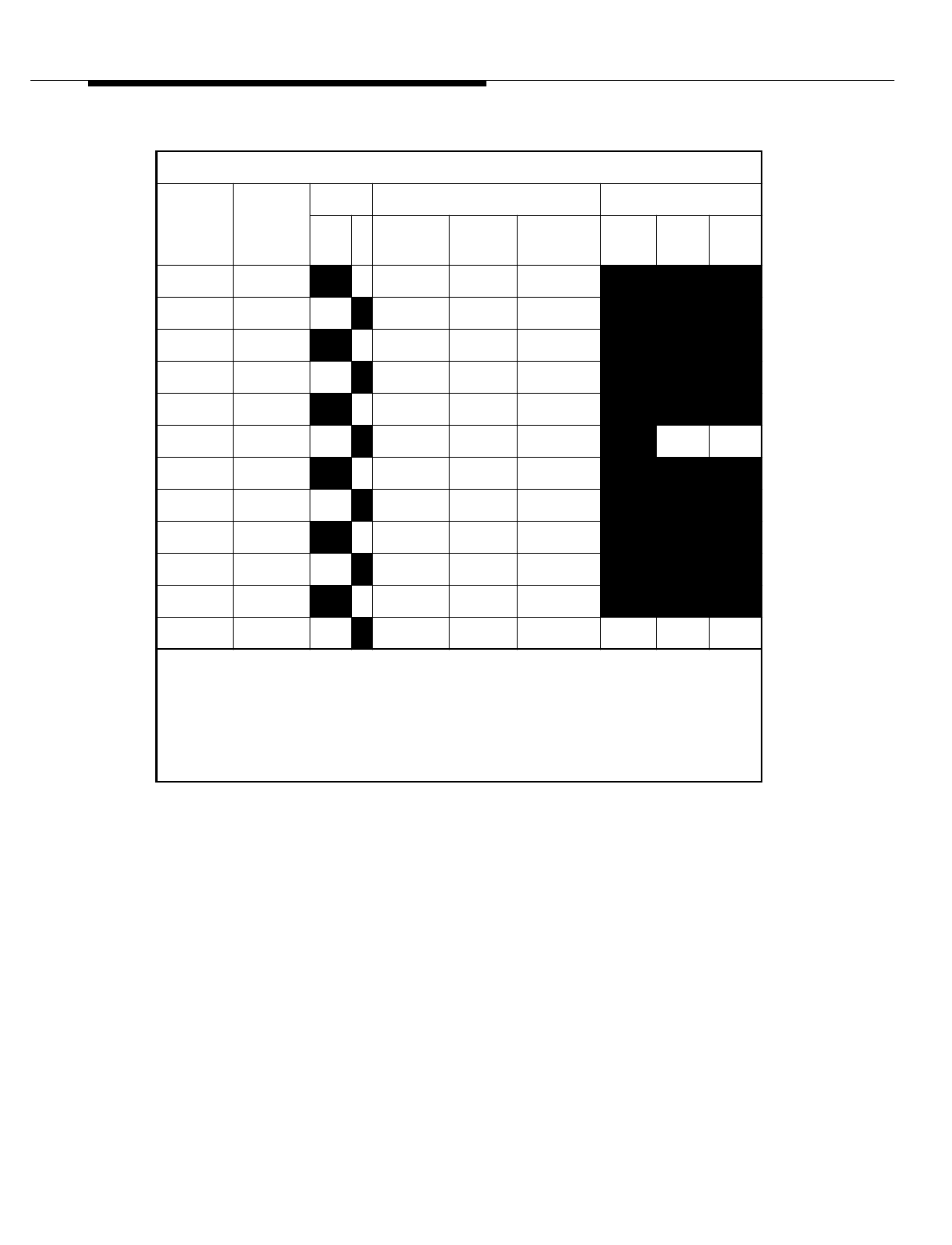
Lucent Technologies — Proprietary
See notice on first page
401-660-100 Issue 11 August 2000 11-43
Cell Site Hardware Functions and Interconnections
Figure 11-15. Information Sheets for T1 D4 and ESF Framing Format
(Sheet 1 of 3)
D4 Framing Format
Frame
Number Bit
Number F Bit* Bit Use in Each Channel Signaling Options†
Fs F
tTraffic YA‡ Signaling None 2-ST 4-ST
10–1Bits 1–8 Bit 2 None – – –
2 193 0 –Bits 1–8 Bit 2 None – – –
3 386 –0Bits 1–8 Bit 2 None – – –
4 579 0 –Bits 1–8 Bit 2 None – – –
5 772 –1Bits 1–8 Bit 2 None – – –
6 965 1 –Bits 1–7 Bit 2 Bit 8§ – AA
7 1158 –0Bits 1–8 Bit 2 None – – –
8 1351 1 –Bits 1–8 Bit 2 None – – –
9 1544 –1Bits 1–8 Bit 2 None – – –
10 1737 1 –Bits 1–8 Bit 2 None – – –
11 1930 –0Bits 1–8 Bit 2 None – – –
12 2123 0 –Bits 1–7 Bit 2 Bit 8 –AB
* F bit sequence is Fs sequence interleaved with Ft sequence.
†Signaling option None: No robbed-bit signaling (bit 8 is used for traffic).
Signaling option 2-ST: 2-state signaling (channel A only).
Signaling option 4-ST: 4-state signaling (channels A and B).
‡Remote yellow alarm – Bit 2 of each channel is set to a 0.
§Robbed-bit signaling.
** Remote Japanese yellow alarm – Fs bit in frame 12 is set to a 1.

Lucent Technologies — Proprietary
See notice on first page
11-44 401-660-100 Issue 11 August 2000
Cell Site Hardware Functions and Interconnections
Figure 11-16. Information Sheets for T1 D4 and ESF Framing Format
(Sheet 2 of 3)
Frame
Number Bit
Number F Bit* Bit Use in Each
Channel Signaling Options†
F
eD
LCR
CTraffic Signaling
‡No
ne 2-
ST 4-
ST 16-
ST
10–D–Bits 1–8 None ––––
2 193 –– C1 Bits 1–8 None ––––
3 386 –D–Bits 1–8 None ––––
4 579 0 –– Bits 1–8 None ––––
5 772 –D–Bits 1–8 None ––––
6 965 –– C2 Bits 1–
7‡
Bit 8‡–AAA
7 1158 –D–Bits 1–8 None ––––
8 1351 0 –– Bits 1–8 None ––––
9 1544 –D–Bits 1–8 None ––––
10 1737 –– C3 Bits 1–8 None ––––
11 1930 –D–Bits 1–8 None ––––
12 2123 1 –– Bits 1–
7‡
Bit 8‡–ABB
13 2316 –D–Bits 1–8 None ––––
14 2509 –– C4 Bits 1–8 None ––––
15 2702 –D–Bits 1–8 None ––––
16 2895 0 –– Bits 1–8 None ––––
17 3088 –D–Bits 1–8 None ––––
18 3281 –– C5 Bits 1–
7‡
Bit 8‡–AAC
19 3474 –D–Bits 1–8 None ––––
20 3667 1 –– Bits 1–8 None ––––
21 3860 –D–Bits 1–8 None ––––
22 4053 –– C6 Bits 1–8 None ––––
23 4246 –D–Bits 1–8 None ––––
24 4439 1 –– Bits 1–
7‡
Bit 8‡–ABD
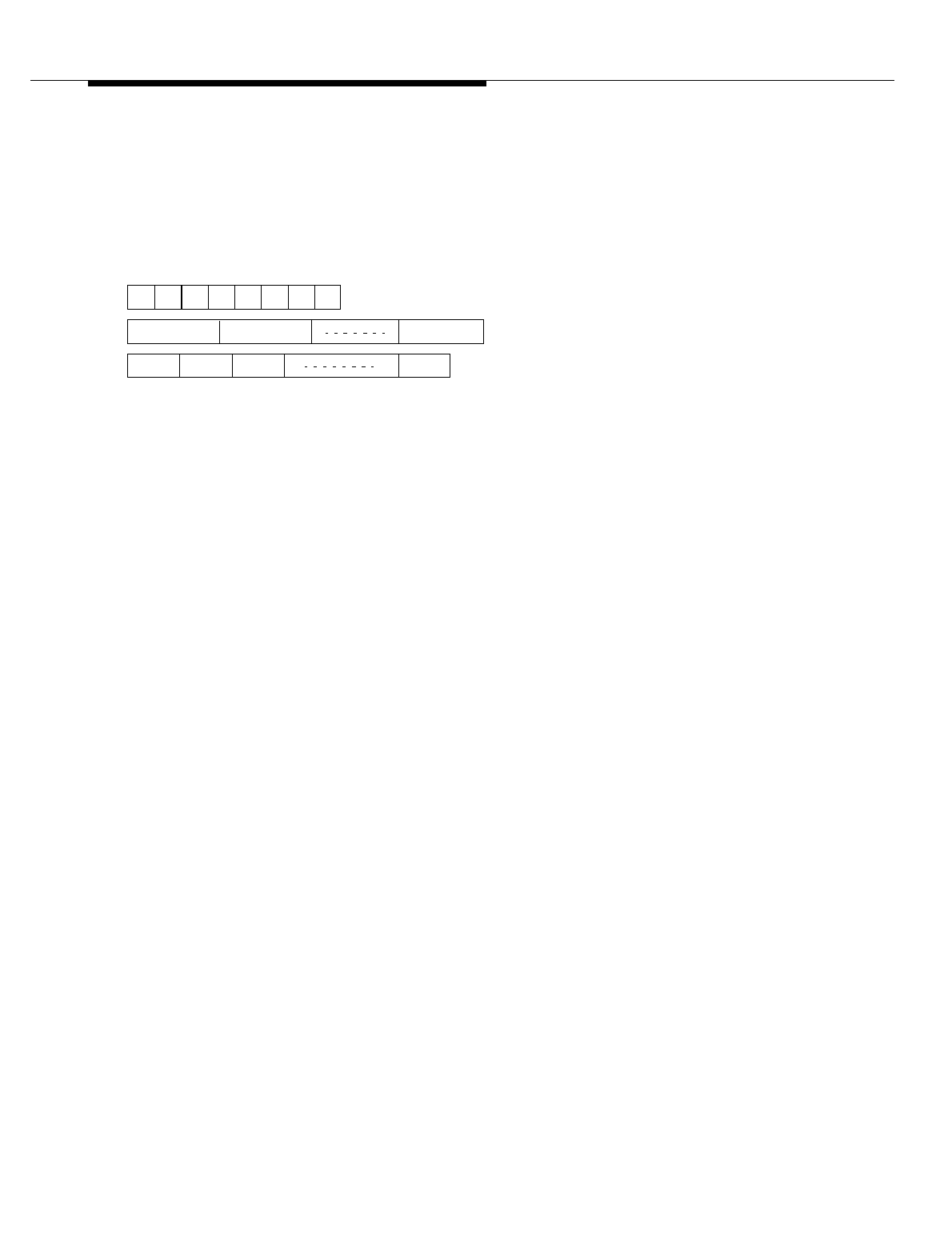
Lucent Technologies — Proprietary
See notice on first page
401-660-100 Issue 11 August 2000 11-45
Cell Site Hardware Functions and Interconnections
Figure 11-17. Information Sheets for T1 D4 and ESF Framing Format
(Sheet 3 of 3)
CEPT-1, for Conference of European Postal and Telecommunications administrations, is the
lowest level of hierarchy in the European E-carrier system. CEPT-1 and E1 are equivalent terms.
Frame and Multiframe. The following illustration shows the basic CCITT CEPT frame and
multiframe structures.
The CCITT CEPT framing format consists of thirty-two 64 kbit/s timeslots, or channels,
resulting in a 256-bit frame and a line rate of 2048 kbit/s (CEPT-1 rate). Framing
information is carried in timeslot 0 (TS0), while local exchange carrier (LEC) signaling
information, if used, is carried in timeslot 16 (TS16).
Framing information is contained in the TS0 frame alignment signal (FAS) word and the
TS0 not-word. The TS0 FAS word is defined as the TS0 byte containing a 0011011
pattern in bit positions 2 through 8. The TS0 not-word is defined as the TS0 byte that
does not contain the FAS pattern. TS0 FAS-word frames interleave with TS0 not-word
frames, as shown in the facing table.
The CCITT CEPT line may contain both a TS0 and a TS16 multiframe. Both multiframes
consist of 16 frames.
TS0 Multiframe. The TS0 multiframe, also known as the cyclic redundancy check
(CRC) multiframe, is used in systems that use the CRC-4 error checking, which is an
enhanced error-monitoring capability providing for additional protection against
emulation of the FAS-word pattern. The multiframe is divided into two submultiframes,
each consisting of eight frames. The multiframe is found by looking for the 001011
pattern in bit position 1 of TS0. This pattern is interleaved with the CRC-4 bits.
Note that association of frame numbers to TS0s is only applicable to the CEPT format
with CRC-4. In CEPT without CRC-4, only two types of names can be identified: frames
containing the TS0 FAS word, and frames not containing the TS0 FAS word (the TS0
not-word).
12345678
Timeslot 0 Timeslot 1 Timeslot 31
FR 0 FR 1 FR 2 FR 15
256-Bit Frame – 125 µs
8-Bit Timeslot, or Channel – 3.91 µs
16-Multiframe – 2 ms

Lucent Technologies — Proprietary
See notice on first page
11-46 401-660-100 Issue 11 August 2000
Cell Site Hardware Functions and Interconnections
ZCS or B8ZS Line Format
T1 standards require an average of at least one 1 in every eight bits of transmitted
data. The T1 framing format uses zero code suppression (ZCS) or binary 8 zero
substitution (B8ZS) to meet this requirement. The ZCS scheme inserts a 1 after
every seventh-consecutive 0 to keep the density of 1s high enough to preserve
accurate timing at the remote endpoint. The remote endpoint removes the
inserted 1.
The B8ZS scheme is used for those applications requiring clear-channel
transmission*. When eight consecutive 0s occur in a bit stream, the B8ZS scheme
replaces the eight 0s with a specific pattern to keep the density of 1s high enough
to preserve accurate timing at the remote endpoint. The remote endpoint
recognizes the pattern and replaces it with the original string of eight 0s.
The T1 line format configuration (ZCS or B8ZS) is specified via translations.
Line-length Compensation Setting
There are five line-length compensation settings for T1 operation: 0 to 133 feet,
134 to 266 feet, 267 to 399 feet, 400 to 533 feet, and 534 to 655 feet. A line-length
compensation setting offsets the cable loss in the path between the DFI and its
associated channel service unit (CSU).
The line-length compensation setting is specified via translations.
Before a DFI is initialized, that is, during powerup or after a reset (at which time
the DFI is transmitting an all 1s signal, or blue alarm, onto the T1 line), the DFI
transmits in accordance to the line-length compensation setting of on-board
switches SW6 and SW7. Once the DFI is initialized, it transmits in accordance to
the line-length compensation setting specified in translations.
Enable or Disable On-demand LLB or BLB Control
Line loopback (LLB), board loopback (BLB), or both can be enabled so that the
loopback can be invoked on demand through the microprocessor interface. The
LLB loops the received signal from the line back to the transmit side without
removing bipolar violations; a blue alarm (all 1s) is sent to the system (toward
TDM bus). When BLB is enabled, the system data is fully processed by PAC and
is then looped back to the system, but is not transmitted to the line; a blue alarm is
sent to the line.
* Clear-channel transmission means that the full capacity of the T1 line is available to the user, that is, no portion of
the channel is reserved for carrier framing or control bits.

Lucent Technologies — Proprietary
See notice on first page
401-660-100 Issue 11 August 2000 11-47
Cell Site Hardware Functions and Interconnections
Enabling or disabling of on-demand LLB/BLB control is not translatable. Cell Site
system software disables this configuration option for both PAC devices.
Select Synchronization Reference
The 8-kHz signal derived from the received T1 data can be supplied back to the
TDM clock source on the CAT.
Selecting a synchronization reference is not translatable. Cell Site system
software determines whether the DFI is selected as a synchronization reference.
Specify Idle Code
All inactive T1 transmit timeslots will contain an idle code, which is a
programmable 8-bit pattern.
Selecting an idle code is not translatable. Cell Site system software sets the idle
code to 11111110.

Lucent Technologies — Proprietary
See notice on first page
11-48 401-660-100 Issue 11 August 2000
Cell Site Hardware Functions and Interconnections
DFI Initialization Message for E1
Operation
The initialization message sets configuration parameters on the PAC and T1/
CEPT line interface devices and may specify a synchronization reference for the
TDM clocks. Configuration parameters for E1 operation include:
CEPT Framing
with or without
CRC-4 Error
Checking
To accommodate framing patterns, error detection, and signaling modes, 16
individual CEPT frames are grouped together to form a multiframe structure. Two
different multiframe formats are defined: one associated with timeslot 0 (TS0) and
the other associated with timeslot 16 (TS16). The TS0 multiframe structure
provides an error checking capacity using a CRC-4 algorithm as defined by
CCITT Recommendation G.704 (See Figure 11-18).
The CEPT framing configuration (with or without CRC-4 error checking) is
specified via translations.
CCS or CAS
Signaling Mode Common-channel signaling (CCS) and channel-associated signaling (CAS) are
signaling modes associated with the TS16 multiframe structure. In the CCS mode,
TS16 is available to carry user (digital-voice) data. In the CAS mode, TS16 is
reserved for local exchange carrier (LEC) signaling and therefore is not available
to carry user data.
The CEPT signaling mode (CCS or CAS) is specified via translations.

Lucent Technologies — Proprietary
See notice on first page
401-660-100 Issue 11 August 2000 11-49
Cell Site Hardware Functions and Interconnections
Figure 11-18. Information Sheets for CCITT CEPT Frame Format
With and Without CRC-4
Frame
Number
Bit Use in TS0 Bit Use in TS16
1234567812345678
0C1/
Si 00110110000X0YmX1X2
1 0 /Si 1 Yf Sa4 Sa5 Sa6 Sa7 Sa8 A1 B1 C1 D1 A17 B17 C17 D17
2C2/
Si 0011011A2B2C2D2A18B18C18D18
3 0 /Si 1 Yf Sa4 Sa5 Sa6 Sa7 Sa8 A3 B3 C3 D3 A19 B19 C19 D19
4C3/
Si 0011011A4B4C4D4A20B20C20D20
5 1 /Si 1 Yf Sa4 Sa5 Sa6 Sa7 Sa8 A5 B5 C5 D5 A21 B21 C21 D21
6C4/
Si 00 1 10 1 1 A6B6C6D6A22B22C22D22
7 0 /Si 1 Yf Sa4 Sa5 Sa6 Sa7 Sa8 A7 B7 C7 D7 A23 B23 C23 D23
8C1/
Si 0011011A8B8C8D8A24B24C24D24
9 1 /Si 1 Yf Sa4 Sa5 Sa6 Sa7 Sa8 A9 B9 C9 D9 A25 B25 C25 D25
10 C2/
Si 0011011A10B10C10D10A26B26C26D26
11 1 /Si 1 Yf Sa4 Sa5 Sa6 Sa7 Sa8 A11 B11 C11 D11 A27 B27 C27 D27
12 C3/
Si 0011011A12B12C12D12A28B28C28D28
13 E /
Si 1 Yf Sa4 Sa5 Sa6 Sa7 Sa8 A13 B13 C13 D13 A29 B29 C29 D29
Ai—Di —Per-channel signaling bits
C1—C4 —CRC-4 bits
E—Remote end block error bits
Si —International spare bits
Sa4—Sa8 —Additional spare bits for national use
X0—X2 —X spare bits
Yf —Remote frame alarm (RFA) bit (active high)
Ym —Remote multiframe alarm (RMA) bit (active high)

Lucent Technologies — Proprietary
See notice on first page
11-50 401-660-100 Issue 11 August 2000
Cell Site Hardware Functions and Interconnections
HDB3 or
Transparent Line
Format
CEPT standards require an average of at least one 1 in every eight bits of
transmitted data. The CEPT framing format uses high-density binary 3 (HDB3)
zero code suppression to meet this requirement. When four consecutive 0s occur
in a bit stream, the HDB3 scheme replaces the four 0s with a specific pattern to
keep the density of 1s high enough to preserve accurate timing at the remote
endpoint. The remote endpoint recognizes the pattern and replaces it with the
original string of four 0s. In contrast, the transparent line format allows the transmit
bit stream to pass through without being modified.
The CEPT line format configuration (HDB3 or transparent) is specified via
translations.
Enable or Disable
On-demand LLB
or BLB Control
Line loopback (LLB), board loopback (BLB), or both can be enabled so that the
loopback can be invoked on demand through the microprocessor interface. The
LLB loops the received signal from the line back to the transmit side without
removing bipolar violations; an alarm indication signal (AIS, all 1s) is sent to the
system (toward TDM bus). When BLB is enabled, the system data is fully
processed by PAC and is then looped back to the system, but is not transmitted to
the line; an AIS is sent to the line.
Enabling or disabling of on-demand LLB/BLB control is not translatable. Cell Site
system software disables this configuration option for both PAC devices.
Select
Synchronization
Reference
The 8-kHz signal derived from the received CEPT data can be supplied back to
the TDM clock source on the CAT.
Selecting a synchronization reference is not translatable. Cell Site system
software determines whether the DFI is selected as a synchronization reference.
Select Idle Code All inactive CEPT transmit timeslots will contain an idle code, which is a
programmable 8-bit pattern.
Selecting an idle code is not translatable. Cell Site system software sets the idle
code to 11111110.
DFI Network-
Update Talk
Message
A network-update “Tal k” message is required to select a digital facilities receive
timeslot and assign it to a TDM transmit timeslot. (This message is used to
program the SNPEs.) It defines the timeslot of the carrier line that the DFI will
receive data from and the timeslot of the TDM bus to which it will be transmitted.
NOTE:
TDM buses are always installed "red stripe up."
DFI Network-
Update Listen
Message
A network-update “Listen” message is required to select a TDM receive timeslot
and assign it to a digital facilities transmit timeslot. (This message is used to
program the SNPEs.) It defines the timeslot of the TDM bus that the DFI will
receive data from and the timeslot of the carrier line to which it will be transmitted.

Lucent Technologies — Proprietary
See notice on first page
401-660-100 Issue 11 August 2000 11-51
Cell Site Hardware Functions and Interconnections
DFI Status Indicators
The DFI faceplate has three light-emitting diode (LED) indicators, one red, one
yellow, and one green. Their meanings are as follows:
Red LED Controlled by the DFI; lighted during the self-test initiated upon powerup or after a
reset and goes off after successful completion of the self-test; lighted during
normal operation if the DFI is insane.
Yellow LED Controlled by Cell Site system software; lighted if the DFI detects any alarm other
than a minor, misframe, or slip alarm for T1 operation (or a 10e-6 error-ratio or slip
alarm for E1 operation) on the line connected to the DFI.
Green LED Controlled by Cell Site system software; the DFI selected as a synchronization
reference has this LED lighted; only one DFI (or DS1) can have the green LED
lighted for the TDM bus (TDM0 or TDM1); if the local oscillator on the CAT is the
synchronization reference for the TDM bus, no DFI (or DS1) will have its green
LED lighted for that bus.
During normal operation and assuming the DFI is not the synchronization
reference, all three of its LEDs should be off. Also, as a troubleshooting aid, if the
red and yellow LEDs are lighted, suspect that the line switches on the DFI are set
to the wrong settings.

Lucent Technologies — Proprietary
See notice on first page
11-52 401-660-100 Issue 11 August 2000
Cell Site Hardware Functions and Interconnections
CAT (TN170) Circuit Description
The CAT performs three independent functions:
1. Bus clock generation and monitoring for the TDM bus
2. Maintenance tone generation
3. Maintenance tone detection and measurement.
These functions are implemented by the TDM bus clock generator circuit, the tone
generator circuit, and the tone detector circuit .
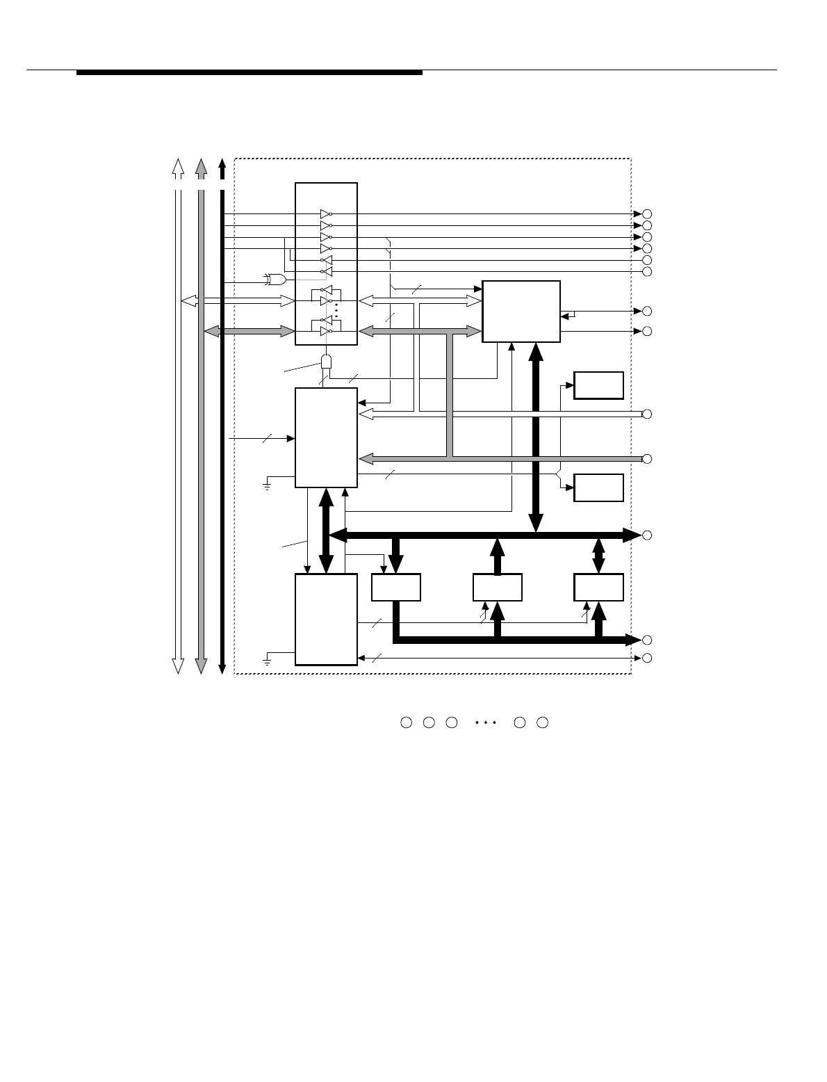
Lucent Technologies — Proprietary
See notice on first page
401-660-100 Issue 11 August 2000 11-53
Cell Site Hardware Functions and Interconnections
Figure 11-19. CAT Block Diagram (Sheet 1 of 2)
(8-BIT MICRO-
PROCESSOR)
ANGEL
BUS
TRANSCEIVERS
SAKI
(BUS SANITY
AND CONTROL
INTERFACE)
EPROM
(BOOT) SRAM
ADDR LATCH ENABLE
EA
2
6
2
PORT 2 DATA
ADDR/ DATA (8)
ADDR (8)
ANA
NPE
(NETWORK
PROCESSING
ELEMENT)
22
GRD
(ANGEL
MODE)
RESET
TX/RX
CONTROL
(HARDWIRED
SLOT ADDR)
7
TDM BUS INTERFACE
AB
GRN LED
(ACT CLK)
RED LED
(FAILURE)
A
L M TO/ FROM SHEET 2
A B C
BA4
DATA (8)
8
DATA (8)
6 3
B
C
D
E
F
G
I
J
K
L
M
(NOTE)
TDMSYNC2
TDMSYNC1
TDMFR
TDMCLK
H
512-kHz CLK
2
TDM0/1 BUS
TDM CLOCK AND CONTROL BUS
NOTE:
ADDRESS
LATCH
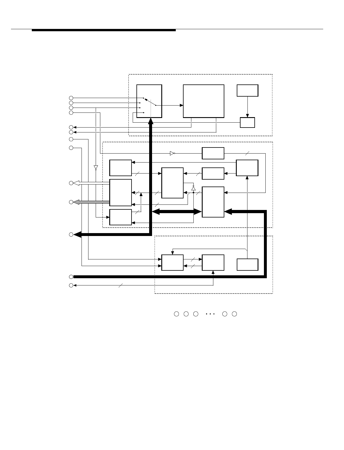
Lucent Technologies — Proprietary
See notice on first page
11-54 401-660-100 Issue 11 August 2000
Cell Site Hardware Functions and Interconnections
Figure 11-20. CAT Block Diagram (Sheet 2 of 2)
L M TO/ FROM SHEET 1
A B C
8
I
J
K
L
M
SYNC SOURCE
REF SELECT
A
B
C
D
E
F
TDMSYNC2
TDMSYNC1
TDMFR
TDMCLK
2048 kHz
8 kHz
LOCAL OSC
(2048 kHz)
*
8-BIT COUNTER (COUNTS FROM 0 TO 255)
BUS
INTERFACE
CONTROL TIMESLOT
TA B LE
(DUAL-PORT
RAM)
AD
AD
8-BIT
COUNTER*
TG DSP
TONE
TABLE
(DUAL-PORT
RAM)
AD
AD
SERIAL IN/
PA R AL L EL
OUT
G
TIMESLOT
COUNTER*
H
PORT 2 DATA
TD DSP I/O
INTERFACE
BUS A/B SELECT
CLOCK
GENERATOR
(PHASE LOCK
LOOP)
8-kHz REF
8-MHz
OSC
512-kHz CLK
ADDR (8)
ADDR/ DATA (8)
TDM BUS CLOCK GENERATOR CIRCUIT
TONE GENERATOR CIRCUIT
COUNT
GENERATOR
8
8
8 8
8
8
8
÷
BY
256
8-kHz LOC
TONE DETECTOR CIRCUIT
5
2
ENB
ENB
2

Lucent Technologies — Proprietary
See notice on first page
401-660-100 Issue 11 August 2000 11-55
Cell Site Hardware Functions and Interconnections
Bus Clock Generation and Monitoring
for the TDM Bus
The TDM bus clock generator circuit provides an 8-kHz frame clock and a 2048-
kHz timeslot clock for the TDM bus (TDM0 or TDM1). Possible synchronization
references are the 8-kHz frame clock (TDMFR ), 2 8-kHz signals derived from the
carrier lines via the DS1 or DFI (TDMSYNC1 and TDMSYNC2 ), and the 8-kHz
signal derived from the on-board local reference oscillator (8-kHz LOC ).
The TDM bus clock generator circuit monitors both the 8-kHz reference signal and
the 8-kHz output clock of the phase lock loop (PLL) to determine when a slip
occurs and to record the number of slips. A slip is declared when the 8-kHz output
clock of the PLL moves one clock cycle ahead or one clock cycle behind the 8-kHz
reference signal. (Presumably, this happens when the 8-kHz reference signal has
a large degree of jitter, or is out of the frequency range of the PLL.) The CAT
declares a loss of signal when a specified number of slips occur in any 5-ms
period; the default value upon powerup or after a reset is 10.

Lucent Technologies — Proprietary
See notice on first page
11-56 401-660-100 Issue 11 August 2000
Cell Site Hardware Functions and Interconnections
Maintenance Tone Generation
The tone generator circuit provides test tones for system diagnostics and
maintenance. These tones are transmitted on the TDM bus for detection and
measurement by the tone detector circuit. There are two tone-generator sources:
the tone generator digital signal processor (TG DSP) and the count generator.
The TG DSP generates the following tones:
404Hz at-16 dBm
1004Hz at-16 dBm
1004Hz at 0 dBm
2804Hz at-16 dBm
1000Hz at 0 dBm (digital miliwatt).*
The TG DSP generates new values for each tone every TDM bus frame (125
microseconds) and stores them in the tone table. The tone table is a dual-port
RAM that is written by the TG DSP and read by the timeslot table (also a dual-port
RAM). The tone table is logically split into two RAMs; the TG DSP writes into one
half, while the timeslot table supplies an address to read the other half. Every
TDM bus frame, special hardware alternates the TG-DSP and timeslot-table
access to each half of memory, to guarantee that stable data is written to the TDM
bus.
Both the angel microprocessor and the timeslot counter access the timeslot table.
The address of each of the 256 memory locations in the timeslot table is
associated with a timeslot on the TDM bus. To enable a tone x on timeslot y, the
angel microprocessor writes an 8-bit code for tone x into address y of the timeslot
table. The 8-bit code consists of six address bits for the tone table, one of which
also enables the tone table (and disables the count generator), and two bus-select
bits that determine whether the tone table connects to highway A or highway B, or
both. The timeslot counter, which is incremented by the TDM timeslot clock (2048
kHz), supplies the addresses (0 through 255) to read the timeslot table.
To enable the count generator on timeslot y, the angel microprocessor writes an 8-
bit code into address y of the timeslot table. The 8-bit code consists of five unused
bits, one bit that enables the count generator (and disables the tone table), and
two bus-select bits that determine whether the count generator connects to
highway A or highway B, or both. The count generator, which is clocked by the
TDM frame clock (8 kHz), continually cycles through a count of 0 through 255.
* The digital miliwatt, or dmW, is a 1-kHz sine-wave tone at a power level of 1 miliwatt (0 dBm). It is the standard
reference level generated by eight 8-bit words as defined by the CCITT.

Lucent Technologies — Proprietary
See notice on first page
401-660-100 Issue 11 August 2000 11-57
Cell Site Hardware Functions and Interconnections
Maintenance Tone
Detection and
Measurement
The tone detector circuit consists of a tone detector digital signal processor (TD
DSP), an angel input/output interface, and an 8-MHz oscillator. Port 2 of the
network processing element (NPE) supplies the tone/count data from the TDM
bus to the TD DSP. The angel commands the TD DSP to detect and measure a
specific tone/count, and the DSP returns the measurement value to the angel.
The angel programs the NPE in accordance to two messages received from the
CPU: a network-update “Listen” message and a network-update “Talk” message.
A network-update “Listen” message defines the timeslot of the TDM bus from
which the tone detector circuit will receive data. A network-update “Talk ” message
defines the timeslot of the TDM bus onto which the output of the tone generator
circuit will be transmitted. The NPE controls when data is transmitted to and
received from the TDM bus via the Tx/Rx control circuit.

Lucent Technologies — Proprietary
See notice on first page
11-58 401-660-100 Issue 11 August 2000
Cell Site Hardware Functions and Interconnections
CAT Status Indicators
The CAT faceplate has two LED indicators, one red and one green. Their
meanings are as follows:
Red LED This indicator is controlled by the CAT. The indicator is lighted during the self-test
initiated upon powerup or after a reset and goes off after successful completion of
the self-test; lighted during normal operation if the CAT is insane.
Green LED This indicator is controlled by Cell Site system software. The CAT selected as the
TDM clock source has this LED lighted. The CPU sends a message to the NCI
(NCI0 for TDM0 and NCI1 for TDM1) specifying which of the two CATs is to supply
the TDM system clocks for the bus. The NCI, in turn, uses the TDMCKSEL control
line to activate the specified CAT.

Lucent Technologies — Proprietary
See notice on first page
401-660-100 Issue 11 August 2000 11-59
Cell Site Hardware Functions and Interconnections
Automatic Recovery Actions
All Cell Site faults fall into one of two categories, depending on the way they are
handled:
■Those faults dealt with initially by the Cell Site, where there may or may not
be follow-up action by the technician
■Those faults dealt with only by the technician.
The first category of faults involves Cell Site equipment having associated
software diagnostic tests. The second category of faults pertains to scanned
alarms, which are faults gathered from Cell Site equipment having no associated
software diagnostic tests. This section deals with a subset of the first category of
faults. Specifically, this section describes automatic recovery actions for the RCC,
DS1/ DFI, and CAT.
The RCC contains software that takes automatic recovery actions (corrective
actions) upon fault recognition. Recovery includes fault isolation and
reconfiguration.
The recovery actions are dependent on the fault type. The RCC may take the
suspect unit out-of-service and perform a diagnostic test on it. If the unit fails the
diagnostic test, it is left in the out-of-service state. If the faulty unit belongs to the
RCC controller, the entire controller is taken out-of-service, and its redundant
mate is made the active controller.
The RCC reports the Cell Site faults to the ECP, including the results of RCC-
initiated diagnostic tests. The RCC also reports any change in equipment
(hardware) status as a result of the recovery action.

Lucent Technologies — Proprietary
See notice on first page
11-60 401-660-100 Issue 11 August 2000
Cell Site Hardware Functions and Interconnections
Hardware Error Handling Strategy
The automatic recovery actions in the RCC are done through the hardware error
handler (HEH) software subsystem. HEH receives errors from hardware units,
functional tests, and call-processing software. It determines when a recovery
action (restore or remove) is needed and then issues a request to carry out the
action.
Depending upon the severity of the error, either HEH takes immediate recovery
action or waits until the error has occurred a predefined number of times before
taking action. For other errors, HEH prints only an error report.
A throttling mechanism at the cell limits the number of alarms reported on a per
board basis to the ECP. Within each 15-minute period, HEH reports no more than
one alarm for any particular board.
HEH performs the following types of error analysis:
Immediate Action For severe errors that are service-affecting, such as loss of communication
between the MSC and the cell, HEH takes immediate action. For most on-board
hardware errors, HEH will request a conditional restore of the suspect unit.
The conditional restore maintenance action schedules an event or process to
restore the suspect unit after the unit passes a diagnostic test. If the unit fails the
diagnostic test, the conditional restore aborts. The failed unit remains in the out-
of-service state.
All Tests Pass
(ATP) Analysis For an HEH-initiated conditional restore request, if the unit passes all diagnostic
tests, the unit is restored to service, and HEH adds a count to an ATP counter for
the unit. If that count exceeds an assigned threshold within a predefined time
period (typically three in 40 minutes or five in 24 hours), HEH will request a
conditional remove of the unit. (Possibly, the diagnostic tests for the unit are not
robust enough to detect the problem, or the problem is external to the unit.) This
type of error analysis prevents a recovery cycle that might otherwise continue
indefinitely.
Single Time-
period Analysis Refers to the use of error counters assigned to each hardware unit (DS1, DFI,
CAT, and so on). If an error count for a unit remains below a predefined threshold
for a specific period of time, HEH clears the counter. This type of error analysis is
based on the theory that if a unit has remained reliable for an extended period of
time, its error history should be forgotten completely. A timer value of 40 minutes
is used.
Fail/Pass Analysis HEH performs this type of error analysis on call-processing detected errors such
as voice channel confirmation failures. When the number of failures exceeds

Lucent Technologies — Proprietary
See notice on first page
401-660-100 Issue 11 August 2000 11-61
Cell Site Hardware Functions and Interconnections
some predefined value relative to the number of successful attempts (such as
2400 failures in 4000 attempts), HEH takes recovery action.
Leaky Bucket
Analysis Refers to the decrementing of non-zero error counters for the configurable
hardware units. The decrementing is done at set time intervals. This technique is
more flexible than a simple analysis based on the number of errors in a single
fixed period of time.

Lucent Technologies — Proprietary
See notice on first page
11-62 401-660-100 Issue 11 August 2000
Cell Site Hardware Functions and Interconnections
RCC Hardware Errors and Recovery
Actions
A fault within any of the units of the active RCC controller causes HEH to shut
down the controller and to activate the mate RCC controller, assuming the mate
RCC controller is in the standby state. If the mate RCC controller is out-of-service,
HEH takes no action other than to unconditionally remove the active RCC; at that
point, both RCCs would be out-of-service.
Assuming the mate RCC is in standby, HEH conditionally restores the active RCC
to standby. This action spawns the following actions:
■A switch request that moves the active RCC to standby and the mate RCC
to the active state.
■A remove request that moves the standby RCC to the out-of-service state.
■A diagnose request that diagnoses the out-of-service RCC; if successful,
results in the RCC being restored to the standby state; if not successful,
results in the RCC remaining in the out-of-service state.
NOTE:
The assumption here is that the active RCC is faulty. If, in fact, the standby
RCC is faulty, HEH will conditionally restore the standby RCC to standby—
no switching of RCC sides will occur.

Lucent Technologies — Proprietary
See notice on first page
401-660-100 Issue 11 August 2000 11-63
Cell Site Hardware Functions and Interconnections
DS1/DFI Hardware Errors and
Recovery Actions
The DS1 or DFI provides serial-to-parallel and parallel-to-serial data conversion
between the carrier lines and the TDM buses internal to the RCF frames. It also
provides the external clock source by which all data and signaling transfers are
synchronized over the TDM bus (TDM0 or TDM1).
The automatic fault-recovery procedure for a DS1/DFI depends upon the fault
type for T1 operation and for E1 operation.
Throughout this section, the term “DS1” will be used to collectively represent both
the DS1 and DFI units. Only when there is a need to distinguish between the DS1
and the DFI units will the term “DFI” be used.
HEH sends a slip count inquiry message to the DS1 every half hour, to which the
DS1 responds with the number of slip conditions it has recorded during the last
half hour. If the number of slip conditions is 44 or greater for a DS1 supplying
synchronization for the TDM bus, HEH will change the synchronization reference
to another DS1 or to local (for local oscillator) if no DS1 synchronization reference
is available. This action may occur any time up to one half hour after HEH receives
a DS1 slip count of 44 or greater. If the DS1 slip count exceeds 88, HEH will take
action immediately.
In addition, HEH sends a misframe count inquiry message* to the DS1 every half
hour, to which the DS1 responds with the number of misframe conditions it has
recorded during the last half hour. If the number of misframe conditions is nine or
greater for a DS1 supplying synchronization for the TDM bus, HEH will change the
synchronization reference to another DS1 or to local if no DS1 synchronization
reference is available. This action may occur any time up to one half hour after
HEH receives a DS1 misframe count of nine or greater. If the DS1 misframe count
exceeds 17, HEH will take action immediately.
When a TDM bus is synchronized to local, HEH will attempt to switch to the
primary or secondary reference DS1 every five minutes. The switch will only
proceed if the primary or secondary reference DS1 is now free of alarms and in
the active state.
* T1 operation only. HEH does not send a misframe count inquiry message to a DFI configured for E1 operation.

Lucent Technologies — Proprietary
See notice on first page
11-64 401-660-100 Issue 11 August 2000
Cell Site Hardware Functions and Interconnections
DS1/DFI and T1 Errors—Detailed
Description
This section describes alarms, error reporting, and performance monitoring
functions performed by the DS1. In addition, this section discusses the
subsequent actions that are taken by the DS1 as a result of various alarm
conditions. For important background information concerning T1/DS1 frame
structure as well as two types of superframe structures known as D4 and
extended superframe (ESP).
The DS1 reports autonomously certain error conditions and statistics when a
change of state occurs or a threshold is exceeded. The DS1 effectively filters the
alarms to avoid reporting spurious conditions; that is, an alarm has to occur a
certain amount times within a given time frame before the DS1 will report the
alarm. The DS1 will report only the most serious of any alarms that may be
present at any particular time. The DS1 will also report autonomously when an
alarm ceases (deactivates).
Loss Of Signal
(LOS) The DS1 cannot detect the received signal on the T1 line. The DS1 inhibits the
updating of the received signaling information from the T1 line. (That is, the DS1
blocks the signal of the T1 port to, but not from, the timeslots on the TDM bus
carrying digital-voice or signaling for the T1 port.) It also begins transmitting a
yellow alarm signal to the remote endpoint of the port.
The DS1 declares an LOS when it cannot detect a data signal for approximately
one second, and deactivates LOS when the data signal is present for
approximately 16 seconds.
Blue Alarm The DS1 is receiving an all-1s pattern on the T1 line. The DS1 inhibits the
updating of the received signaling information from the T1 line. It also begins
transmitting a yellow alarm signal to the remote endpoint of the port.
The DS1 declares a blue alarm when it detects an all-1s pattern for approximately
two seconds, and deactivates the blue alarm when the condition is clear for
approximately 16 seconds.
The DS1, itself, will transmit a blue alarm to the remote endpoint during board
initialization, that is, during the on-board self-test initiated upon powerup or after a
system reset.
Red Alarm The DS1 cannot detect the framing pattern in the received signal on the T1 line.
The DS1 inhibits the updating of the received signaling information from the T1
line. It also begins transmitting a yellow alarm signal to the remote endpoint of the
port.

Lucent Technologies — Proprietary
See notice on first page
401-660-100 Issue 11 August 2000 11-65
Cell Site Hardware Functions and Interconnections
The DS1 declares a red alarm when it detects framing errors for approximately
three seconds, and deactivates the red alarm when the condition is clear for
approximately 16 seconds.
In D4 or ESF, a framing error occurs when any two of four, or two of six,
consecutive frame synchronization bits (Fs or Ft in D4, Fe in ESF) are in error.
Major Alarm The received signal on the T1 line has a bit error ratio exceeding 10e-3 over a
predefined period of time. (The average bit error rate exceeds 1 in 1000 bits.) The
DS1 begins transmitting a yellow alarm signal to the remote endpoint of the port,
but transmission and reception over the T1 line proceed with no interruption at this
end of the connection.
The bit error ratio is measured with framing bit errors in D4 and with CRC errors in
ESF. In D4, the DS1 declares a major alarm when the error ratio exceeds 10e-3
for 16 seconds, and deactivates the alarm when the clear threshold has been
reached for 16 seconds. In ESF, the DS1 declares a major alarm when the error
ratio exceeds 10e-3 for 6 seconds, and deactivates the alarm when the clear
threshold has been reached for 6 seconds.
Yellow Alarm The DS1 is receiving a yellow alarm signal from the remote endpoint (that is, the
other endpoint has an LOS, blue alarm, red alarm, or major alarm condition,
although there are no problems at this endpoint). The DS1 takes no action other
than reporting this alarm.
The DS1 reports a yellow alarm condition when the condition persists for
approximately 0.4 seconds, and negates the report when the yellow alarm
condition has ceased for approximately 0.4 seconds.
In D4, a yellow alarm is indicated by a 0 in bit 2 of all incoming channels. In ESF, a
yellow alarm is indicated by an alternating pattern of eight 1s and eight 0s on the
4-kbit/s data link (DL).
The DS1 cannot determine when receiving a yellow alarm whether the channels
are usable—they would be if there were a major alarm at the other end—or not
usable—they would not be if one of the other conditions were in effect.

Lucent Technologies — Proprietary
See notice on first page
11-66 401-660-100 Issue 11 August 2000
Cell Site Hardware Functions and Interconnections
Fan Alarms
Preamp Fan All preamp fans in the Linear Amplifier Frame (LAF) are powered from two of the
four 20A DC feeders which supply power to the LAC 0 position in the frame.
Preamp fans will not have power if the breakers to LAC 0 are open.
To avoid overheating the preamps, do not power down LAC 0 for more than a few
minutes if other Linear Amplifier Modules (LACs) are powered. If LAC 0 needs to
be powered down for an extended period of time, disconnect the J1 power cable
from LAC 0 (LAC 4 in LAF1), and close the two 20A breakers which supply
connector J1.
Symptoms:
C-Series LACs:
Major Alarm
LAC LEDS = FANS and PREAMP
A/B-Series LACs:
Minor Alarm
LAC LEDS = LINEARIZER
Procedure:
Check that all 20A breakers feeding LAC 0 (LAC 4 in LAF1) are closed.
If a fan is stopped, check its wiring. Check the fan for blockage.
Check the 24-volt DC voltage on connector J1 supplying LAC 0. If normal, the fan
should be replaced. Replace both preamp fans at the same time, even if the other
fan is working normally.
LineariZeR Fan
Procedure Symptoms:
C-Series LACs:
Major Alarm
LAC LEDS = FANS and LINEARIZER
A/B-Series LACs:

Lucent Technologies — Proprietary
See notice on first page
401-660-100 Issue 11 August 2000 11-67
Cell Site Hardware Functions and Interconnections
Minor Alarm
LAC LEDS = LINEARIZER
Procedure:
Check the LINEARIZER FAN fuse on the front panel of the LineariZeR (LZR).
Replace with a new fuse, if blown.
If the fuse is good, remove the front grille from the LZR and carefully check to see
if the fan is turning. The fan is located on the far right side of the LZR cabinet.
Check the fan wiring for shorts or opens. If none are found, replace the fan.
LAU Fan
Procedure Symptoms:
C-Series LACs:
Major Alarm
LAC LEDS = FANS and LAU
A/B-Series LACs:
Minor Alarm
LAC LEDS = LAU
Procedure:
Check the LINEAR AMPLIFIER UNIT FAN fuse on the front panel of the
LineariZeR (LZR) (Figure 4-17). Replace it with a new fuse, if blown.
If the fuse is good, check to see if the fan is turning. Check for blockage. Remove
a few Linear Amplifier Modules (LAMs) at the top of the Linear Amplifier Unit
(LAU) and check the DC voltage at the inductor terminals. If the voltage is greater
than 22V, replace the fan. If the voltage is less than 22V, check the DC power
cabling.
Measuring the
Linear Amplifier
Unit (LAU) Fan
Voltage

Lucent Technologies — Proprietary
See notice on first page
11-68 401-660-100 Issue 11 August 2000
Cell Site Hardware Functions and Interconnections
DS1 Errors
Minor Alarm The received signal on the T1 line has a bit error ratio between 10e-3 and 10e-6
over a predefined period of time. (The average bit error rate is less than 1 in 1000
bits but exceeds 1 in 1,000,000 bits.) The DS1 takes no action other than
reporting this alarm.
The bit error ratio is measured with framing bit errors in D4 and with CRC errors in
ESF. In D4, the DS1 declares a minor alarm when the error ratio exceeds 10e-6
for 41 minutes, and deactivates the alarm when the clear threshold has been
reached for 41 minutes. In ESF, the DS1 declares a minor alarm when the error
ratio exceeds 10e-6 for 10 minutes, and deactivates the alarm when the clear
threshold has been reached for 10 minutes.
Misframe Count The number of framing bit errors detected by the DS1 since the last system
inquiry. The DS1 will report the number of misframes autonomously whenever the
number of misframes reaches 17. The misframe count will be reset (misframe
count = 0) when the DS1 receives a Misframe Count Inquiry message from the
CPU.

Lucent Technologies — Proprietary
See notice on first page
401-660-100 Issue 11 August 2000 11-69
Cell Site Hardware Functions and Interconnections
DFI and E1 Errors - Detailed
Description
This section describes alarms, error reporting, and performance monitoring
functions performed by the DFI configured for E1 operation. In addition, this
section discusses the subsequent actions that are taken by the DFI as a result of
various alarm conditions.
The DFI reports the following autonomous alarms to HEH:*
Loss Of Signal
(LOS) The DFI cannot detect the received signal on the E1 line. The DFI inhibits the
updating of the received signaling information from the E1 line. (That is, the DFI
blocks the signal of the E1 port to, but not from, the timeslots on the TDM bus
carrying digital-voice or signaling for the E1 port.) It also begins transmitting a
remote frame alarm (RFA) signal to the remote endpoint of the port.
The DFI declares an LOS when it cannot detect a data signal for approximately
2.4 seconds, and deactivates LOS when the data signal is present for
approximately 12 seconds.
Alarm Indication
Signal (AIS) The DFI is receiving an all-1s pattern on the E1 line. The DFI inhibits the updating
of the received signaling information from the E1 line. It also begins transmitting
an RFA signal to the remote endpoint of the port.
The DFI declares an AIS when it detects an all-1s pattern for approximately 0.6
seconds, and deactivates AIS when the condition is clear for approximately 0.2
seconds.
The DFI, itself, will transmit an AIS signal to the remote endpoint during board
initialization, that is, during the on-board self-test initiated upon powerup or after a
reset.
Loss of Frame
Alignment (LFA) The DFI cannot detect the framing pattern in the received signal on the E1 line.
The DFI inhibits the updating of the received signaling information from the E1
line. It also begins transmitting an RFA signal to the remote endpoint of the port.
The DFI declares an LFA when it detects framing errors for approximately 2.4
seconds, and deactivates LFA when the condition is clear for approximately 12
seconds.
A framing error is defined as an incorrect bit in one of the seven framing bits in the
timeslot 0 (TS0) frame alignment signal (FAS) word or an error in bit 2 of the TS0
* For any DFI autonomous alarm except the 10e-6 error-ratio alarm and slip count, Cell Site system software will
turn on the DFI’s yellow LED.

Lucent Technologies — Proprietary
See notice on first page
11-70 401-660-100 Issue 11 August 2000
Cell Site Hardware Functions and Interconnections
not-word. The DFI begins a sequential search for new framing candidates, starting
one bit position beyond the position where the LFA was detected and continuing
until a valid candidate is found.
Loss of Multiframe
Alignment (LMA) The DFI cannot detect the multiframe alignment pattern (for the multiframe
selected) in the received signal on an E1 line. The DFI inhibits the updating of the
received signaling information from the E1 line. For a timeslot 16 (TS16) LMA, it
also begins transmitting a remote multiframe alarm (RMA) signal to the remote
endpoint of the port.
The DFI declares a TS0 LMA when an error has occurred in the 6-bit multiframe
pattern (001011 interleaved with the CRC-4 bits) for approximately 2.4 seconds,
and deactivates TS0 LMA when TS0 multiframe alignment has recovered for
approximately 12 seconds.
The DFI declares a TS16 LMA when an error has occurred in the 4-bit multiframe
alignment signal (MAS) pattern for approximately 2.4 seconds, and deactivates
TS16 LFA when TS16 multiframe alignment has recovered for approximately 12
seconds.
10e-3 Error-ratio
Alarm The received signal on the E1 line has a bit error ratio exceeding 10e-3 over a
predefined period of time. (The average bit error rate exceeds 1 in 1000 bits.) The
DFI begins transmitting an RFA signal to the remote endpoint of the port, but
transmission and reception over the E1 line proceed with no interruption at this
end of the connection.
The DFI declares a 10e-3 error-ratio alarm when the frame-alignment error ratio
exceeds 10e-3 for two consecutive four-second periods, and deactivates the
alarm when the clear threshold has been reached for three consecutive four-
second periods.
A frame alignment error, or framing error, is defined as an incorrect bit in one of
the seven framing bits in the TS0 FAS word or an error in bit 2 of the TS0 not-
word.
Remote Frame
Alarm (RFA) The DFI is receiving an RFA signal from the remote endpoint (that is, the other
endpoint has an LOS, AIS, LFA, or 10e-3 error-ratio alarm condition, although
there are no problems at this endpoint). The DFI takes no action other than
reporting this alarm.
The DFI reports the RFA condition when the condition persists for approximately
0.6 seconds, and negates the report when the RFA alarm condition has ceased
for approximately 0.2 seconds.
The DFI cannot determine when receiving an RFA alarm whether the channels
are usable—they would be if there were a 10e-3 error-ratio alarm at the other

Lucent Technologies — Proprietary
See notice on first page
401-660-100 Issue 11 August 2000 11-71
Cell Site Hardware Functions and Interconnections
end—or not usable—they would not be if one of the other conditions were in
effect.
Remote
Multiframe Alarm
(RMA)
The DFI is receiving an RMA signal on an E1 line (that is, the other endpoint has a
TS16 LMA condition, although there are no problems at this endpoint). The DFI
takes no action other than reporting this alarm.
The DFI reports the RMA alarm condition when the condition persists for
approximately 0.6 seconds, and negates the report when the RMA alarm
condition has ceased for approximately 0.2 seconds.
10e-6 Error-Ratio
Alarm The received signal on the E1 line has a bit error ratio between 10e-3 and 10e-6
over a predefined period of time. (The average bit error rate is less than 1 in 1000
bits but exceeds 1 in 1,000,000 bits.) The DFI takes no action other than reporting
this alarm.
The DFI declares a 10e-6 error-ratio alarm when the frame-alignment error ratio
exceeds 10e-6 for 30 minutes, and deactivates the alarm when the clear threshold
has been reached for 45 minutes.
Slip Count The number of times the DS1 has either dropped a frame from the received data
or repeated a frame since the last system inquiry. The DS1 will report the number
of slips autonomously whenever the number of slips reaches 88. The slip count
will be reset (slip count = 0) when the DS1 receives a Slip Count Inquiry message
from the CPU.
The T1 port on the DS1 receives data from a T1 line into a two-frame buffer (by
necessity, at the T1 line rate—8000 frames per second), and empties this buffer
onto the TDM bus (by necessity, at the TDM bus rate). If these rates are not
identical over a significant period of time, then the receive buffer will either
overflow or underflow, resulting in the deletion of a frame or the repeat of a frame.
Each overflow or underflow of the buffer is counted as a single slip.

Lucent Technologies — Proprietary
See notice on first page
11-72 401-660-100 Issue 11 August 2000
Cell Site Hardware Functions and Interconnections
CAT Hardware Errors and Recovery
Actions
The CAT, which is phase-locked to one of the carrier lines attached to the primary
RCF or growth RCF frame, provides system clocks for the TDM bus (either TDM0
or TDM1).
The automatic fault-recovery procedure for a CAT depends upon the fault type
(See Table 11-4).
The CAT monitors both the 8-kHz reference signal and the 8-kHz output clock of
its on-board phase lock loop (PLL) to determine when a slip occurs and to record
the number of slips. A slip is declared when the 8-kHz output clock of the PLL
moves one clock cycle ahead or one clock cycle behind the 8-kHz reference
signal. (Presumably, this happens when the 8-kHz reference signal has a large
degree of jitter, or is out of the frequency range of the PLL.) The CAT declares a
loss of signal error when a specified number of slips occur in any 5-ms period.
The default value upon powerup or after a reset is 10.
The CAT will report a loss of signal error to HEH as soon as it occurs.
HEH sends a slip count inquiry message to the CAT every half hour, to which the
CAT responds with the number of slip conditions it has recorded during the last
half hour. If the number of slip conditions is greater than 44, HEH will send a PPM
inquiry message to the CAT to determine the total parts per million (PPM) counts
detected by the CAT when using the primary or secondary DS1/DFI
synchronization reference. Whether the PPM count is high or low, HEH takes no
recovery action other than to report the PPM count to the ECP.
A high PPM count means that the quality of the reference source (carrier line) is
poor. A further deterioration in the quality of the reference source will cause the
CAT to declare a loss of signal error, at which time HEH will take corrective action.
When a TDM bus is synchronized to local, HEH will attempt to switch to the
primary or secondary reference DS1/DFI every five minutes. The switch will only
proceed if the primary or secondary reference DS1/DFI is now free of alarms and
in the active state.
Call-Processing
Errors and
Recovery Actions
In addition to the hardware faults already described, HEH can detect certain
AMPS, TDMA, and CDMA call-processing related errors.
Diversity Imbalance Errors and Recovery Actions
Diversity imbalance errors are reported autonomously by a Cell Site radio (AMPS,
TDMA, or CDMA) when it perceives widely varying signal strengths in the receive
antennas it is using. The Cell Site will diagnose the radio in question.

Lucent Technologies — Proprietary
See notice on first page
401-660-100 Issue 11 August 2000 11-73
Cell Site Hardware Functions and Interconnections
Manual Recovery Actions
The symptoms described in “DS1/DFI and T1 Errors- Detailed Description”
indicate faults on the T1 facility or faults in the generation of the T1 signal by the
remote end. While it is possible that faults in the DS1/DFI can cause these
symptoms, they are more likely to be the result of a fault outside of the DS1/DFI.
In response to an alarming DS1/DFI that is supplying synchronization for the TDM
bus, The Cell Site automatically switches the synchronization reference to another
DS1/DFI, if available. If switching the synchronization reference to another DS1/
DFI results in no further alarms, the DS1/DFI generating the alarm is probably
faulty. In that case, the DS1/DFI generating the alarm should be conditionally
restored. If the problem persists after taking this action, the digital facilities
termination unit at the remote end is probably faulty; it should be conditionally
restored.
A technician can check whether a DS1/DFI is operating properly by running a
diagnostic test on the DS1/DFI. Or, for T1 operation, a line-related problem can be
isolated to either the Cell Site equipment side of the channel service unit (CSU) or
the T1 facility side of the CSU by putting the CSU in loopback. If the problem goes
away, the T1 facility is at fault. The DS1/DFI port that is looped back should not be
supplying system synchronization at the time it is looped.

Lucent Technologies — Proprietary
See notice on first page
11-74 401-660-100 Issue 11 August 2000
Cell Site Hardware Functions and Interconnections
Table 11-4. CAT Errors and Recovery Actions
Fault Type Description Automatic Recovery Action
CAT insane* CAT-to-CPU communication
broken
If mate is out-of-service, HEH takes
no action other than to
unconditionally remove the active
CAT; at that point, both CATs would
be out-of-service.
Assuming mate is in standby, HEH
conditionally restores the active CAT
to standby, which spawns the
following actions:
1. A switch request that sets
the appropriate control bit
in the NCI control register;
NCI uses TDMCKSEL con-
trol line to move active CAT
to standby and mate CAT
to active state.
2. A remove request that
moves standby CAT to out-
of-service state.
3. A diagnose request that
diagnoses out-of-service
CAT; if successful, results
in CAT being restored to
standby state; if not
successful, results in CAT
remaining in out-of-service
state.
CAT hardware failure Hardware failures include parts
per million (PPM) failure, slip
detector failure, slip in local,
local reference failure, SD0
failure, and SD1 failure.
HEH takes same recovery action as in
case of “CAT insane” condition.
Loss of Signal Excessive number of slip
conditions (10 or more slips
during any 5-ms period)
HEH switches synchronization
reference to another DS1/ DFI if
available; otherwise, HEH switches to
CAT local source.
* The assumption here is that the active CAT is insane. If, in fact, the standby CAT is insane, HEH
will conditionally restore the standby CAT to standby—no switching of CAT units will occur.

Lucent Technologies — Proprietary
See notice on first page
401-660-100 Issue 11 August 2000 11-75
Cell Site Hardware Functions and Interconnections
Or, for E1 operation, assuming that the associated customer-provided network
termination unit (NTU) can be put into loopback, a line-related problem can be
isolated to either the Cell Site equipment side of the NTU or the E1 facility side of
the NTU by putting the NTU in loopback. If the problem goes away, the E1 facility
is at fault. The DFI port that is looped back should not be supplying system
synchronization at the time it is looped.
And finally, for the DFI unit only, if the on-board red and yellow LEDs are lighted,
suspect that the line switches on the DFI are set to the wrong settings.

Lucent Technologies — Proprietary
See notice on first page
11-76 401-660-100 Issue 11 August 2000
Cell Site Hardware Functions and Interconnections

Lucent Technologies — Proprietary
See notice on first page
401-660-100 Issue 11 August 2000 12-1
12
Routine Maintenance and Radio
Performance Tests
Contents
■Contents 12-1
■Maintenance Process 12-3
Maintenance Objective 12-3
Maintenance Activities 12-3
Preventive Maintenance 12-3
Routine Maintenance 12-3
Diagnostic Routines 12-4
Visual Inspection 12-4
Maintenance Assumptions 12-4
Routine Maintenance Procedures List 12-5
Fan Screen Cleaning 12-6
■Radio Performance Testing 12-7
Radio Test Overview 12-7
Radio Pretest Procedure 12-7
Cable Loss Measurement 12-9
Power Measurement 12-12
Voice 1004 Hz Deviation Measurement 12-13
Post Test Procedure 12-15
Transmitter Output Power Verification 12-16

Lucent Technologies — Proprietary
See notice on first page
12-2 401-660-100 Issue 11 August 2000
Routine Maintenance and Radio Performance Tests
Transmitter Output Power Adjustment 12-16

Lucent Technologies — Proprietary
See notice on first page
401-660-100 Issue 11 August 2000 12-3
Routine Maintenance and Radio Performance Tests
Maintenance Process
The maintenance process consists of those activities designed to minimize the
effects of any failure on system performance and to provide the operations
personnel with the information and tools to locate and repair troubles rapidly.
Operators are provided with the necessary information, such as fault and status
information, and the control capability to monitor the system performance and
perform the maintenance functions required to meet system reliability.
The Cell Site is responsible for fault recognition, fault analysis, fault recovery, and
the reporting of faults and hardware maintenance states to the ECP. In those
situations where no automatic recovery action is taken or automatic recovery fails,
it is the responsibility of the technician to perform manual recovery procedures
from the ECP.
Maintenance
Objective The objective of the maintenance process is to:
■Avoid unnecessary system initializations
■Avoid unnecessary manual diagnostics
■Minimize site visits
■Maximize system availability.
Maintenance
Activities Maintenance activities fall into one of three categories:
■Preventive maintenance
■Corrective maintenance
■Controlled maintenance.
Preventive
Maintenance Preventive maintenance consists of those activities performed at regular intervals
that are designed to identify as soon as possible, potential failure conditions and/
or equipment failures. The goal of preventive maintenance is to maintain normal
system operations and to prevent loss of service. That goal is achieved by the use
of software and manual routines.
Software routines include scheduled software diagnostic tests, functional tests,
and audits.
Routine
Maintenance Cell Site routine maintenance tasks are listed in Equipment Test List (ETL). The
Cell Site ETL divides Cell Site routines into three categories: (1) Radio and
Control Equipment — those routines associated with call processing control and
Radio Frequency (RF) transmission; (2) Power Equipment — those routines
associated with on-line power supplies, auxiliary power equipment, and
monitoring equipment; and (3) Building and Environmental Equipment — those
routines associated with temperature and humidity control, fire and safety,
emergency lighting, and building alarms.

Lucent Technologies — Proprietary
See notice on first page
12-4 401-660-100 Issue 11 August 2000
Routine Maintenance and Radio Performance Tests
The order in which routines are listed on the ETL is not intended to indicate a
sequence for performing routines. Routines are performed at the intervals listed in
the Interval column and as described within the routine procedures. The Lucent
Technologies Practice contains a reference to the procedural information required
to perform the cell site tests.
Diagnostic Routines
Diagnostic routines are run automatically by system software and are run
manually when a unit is suspected of being faulty or when a unit is replaced.
Diagnostic tests are run only on off-line units. Lucent Technologies 401-660-101,
Series II Cell Site Diagnostic Test Descriptions, contains a complete description of
the diagnostic tests.
Visual Inspection
Visual inspections at the Cell Site should be made on a bimonthly basis. Typical
visual indications to look for are listed below:
■Alarm lamp indication
■Smoke
■Broken cables
■Blown fuses
■Overheating
■Out-of-range temperature and humidity.
Maintenance
Assumptions It is assumed that the technician is familiar with the following or that such
conditions are otherwise met:
1. Wrist grounding straps must always be attached before working on any
component or handling the Circuit Packs (CPs). This is to prevent or reduce
electrostatic discharge that may damage or destroy circuit packs containing
integrated circuits.
2. Powering down the failing unit (when required), reseating CPs, powering up
the unit, and repeating diagnostics when an initial STF message is
received to verify the corrective action.
3. Replacing one CP at a time when several are suspected, then replacing the
CP, and repeating the diagnostics.
4. Handling CPs by the edges and the faceplates to avoid damaging contacts
and deforming components.
5. Operations of the terminal to include mode changing, page manipulation,
and message conventions.
6. Tagging faulty CPs with office location, mounting location, diagnostic phase
and test that failed, and date removed.

Lucent Technologies — Proprietary
See notice on first page
401-660-100 Issue 11 August 2000 12-5
Routine Maintenance and Radio Performance Tests
7. All test equipment is known to be functioning properly.
8. A replacement unit or CP is known to be good.
9. Burned out lamps or Light Emitting Diodes (LEDs) are replaced without
instruction.
10. Audible alarms are retired without instruction.
Routine
Maintenance
Procedures List
Table 12-1 provides a list of the Routine Maintenance Procedures for the Series II
cell.
Table 12-1. Routine Maintenance Procedures
Routine Maintenance Procedure Performance
Interval Source
Document
RADIO/CONTROL EQUIPMENT
Clean Power Amplifier Cooling 6 mo. 401-201-500
Performance Measurements
Perform Setup Radio Performance Measurements 12 mo. 401-660-100
Perform Voice Radio Performance Measurements 12 mo. 401-660-100
Check Reference Generator Frequency 6 mo.
POWER AND BATTERY PLANT EQUIPMENT
STORAGE BATTERY
Check Float Level 1 mo. 157-629-701
Check Electrolyte Level 1 mo. 157-629-701
Check Cell Voltage 3 mo. 157-629-701
Check Specific Gravity 6 mo. 157-629-701
150B BATTERY POWER PLANT
Check Float Voltage Alarm 12 mo. 167-609-302
Check Fuse Alarms 12 mo. 167-609-302
RECTIFIER (MOD 1)
Check High- and Low-Voltage Alarms 12 mo. 169-652-305
Check Rectifier Failure Alarm 12 mo. 169-652-305
RECTIFIER (MOD II)
Check High- and Low-Voltage Alarms 12 mo. 169-609-311
Check Rectifier Failure Alarm 12 mo. 169-609-311
BUILDING AND ENVIRONMENTAL EQUIPMENT
Air Conditioning Check 1 wk. Local proce-
dure

Lucent Technologies — Proprietary
See notice on first page
12-6 401-660-100 Issue 11 August 2000
Routine Maintenance and Radio Performance Tests
Fan Screen
Cleaning Fan screens require checking/cleaning monthly. Screens should be vacuumed
clean of dirt and cleaned with soap/water to remove any buildup of dirt.
Tower Light Check 1 wk. Local proce-
dure
Humidifier Check 1 wk. Local proce-
dure
Dehumidifier Check 1 mo. Local proce-
dure
Emergency Lighting Check 1 mo. Local proce-
dure
Exhaust Fan Check 1 mo. Local proce-
dure
Fire and Safety Equipment Check 1 mo. Local proce-
dure
Air Dryer Inspection 6 mo. Local proce-
dure
Dust Cell Site Equipment Check 6 mo. Local proce-
dure
Fire Alarm Sensor Cleaning 6 mo. Local proce-
dure
Peripheral Alarms: Door, Fire, AC, Heat Check 6 mo. Local proce-
dure
Smoke Alarm Check 6 mo. Local proce-
dure
Heaters Check 12 mo. Local proce-
dure
Table 12-1. Routine Maintenance Procedures (Contd)
Routine Maintenance Procedure Performance
Interval Source
Document

Lucent Technologies — Proprietary
See notice on first page
401-660-100 Issue 11 August 2000 12-7
Routine Maintenance and Radio Performance Tests
Radio Performance Testing
Radio performance testing should be done annually and whenever any
component of a transmit path is changed or altered (See Figure 12-1). The
procedures for doing radio performance testing are given below.
Radio Test
Overview This procedure describes radio performance tests for power, frequency, and
frequency deviation tests made on the Radio Channel Unit (RCU). This procedure
applies to both setup and Voice RCUs (V-RCUs). These tests are designed to be
run after an RCU is (1) initially installed and (2) when any component of the
transmit path is changed or altered.
At the time of initial installation, the Preamplifier and the RCU associated with
each Linear Amplifier Circuit (LAC) are adjusted and power level measurements
are made to determine the Effective Radiated Power (ERP) from each LAC. All
performance measurements (power, frequency, and deviation) are made at
connector J3 (Incident Port) on the Radio Test Unit (RTU) switch panel. All of
these measurements are recorded in the Cell Site Log to be used as a reference
for these tests and other RCU measurements.
The value of ERP, input to the transmit (TX) antenna, and the power at J3 on the
RTU switch panel should be the same for all RCUs connected to the same LAC.
The maximum allowable ERP is 500 watts per channel.
These performance tests require a Cell Site to Mobile Switching Center (MSC)
data link, the use of a data terminal keyboard, the use of an IFR FM/AM 1500
Communications Service Monitor (CSM) or equivalent, and test cables/adapters.
Radio performance measurements are made in the following order: RCU
Frequency, RCU Effective Radiated Power, RCU Frequency deviation due to 1004
Hz modulation (voice), RCU Frequency due to Supervisory Auditory Tone (SAT),
and RCU Frequency deviation due to 10 kHz (data). Some steps require that input
messages be entered. For each input message, there is a corresponding output
message response. If an interpretation of a message is needed, refer to the Cell
Site Input/Output (I/O) Manual.
The power level measurements made at J3 on the RTU switch panel and recorded
in the Cell Site log at the time of initial installation are used as a reference for
these performance tests. A portion of the power output from each LAC is fed from
its directional coupler to the RTU switch panel (J3). Therefore, the power level at
J3 is a function of the ERP from any RCU connected to the LAC. That is, all RCUs
connected to a given LAC are adjusted to give the same value at J3. When an
RCU is replaced, the new RCU output is adjusted to give the same value recorded
Radio Pretest
Procedure
NOTE:
Run a diagnostic test on the Voice Radio Channel Unit (V-RCU) before
running this test. Perform the following:
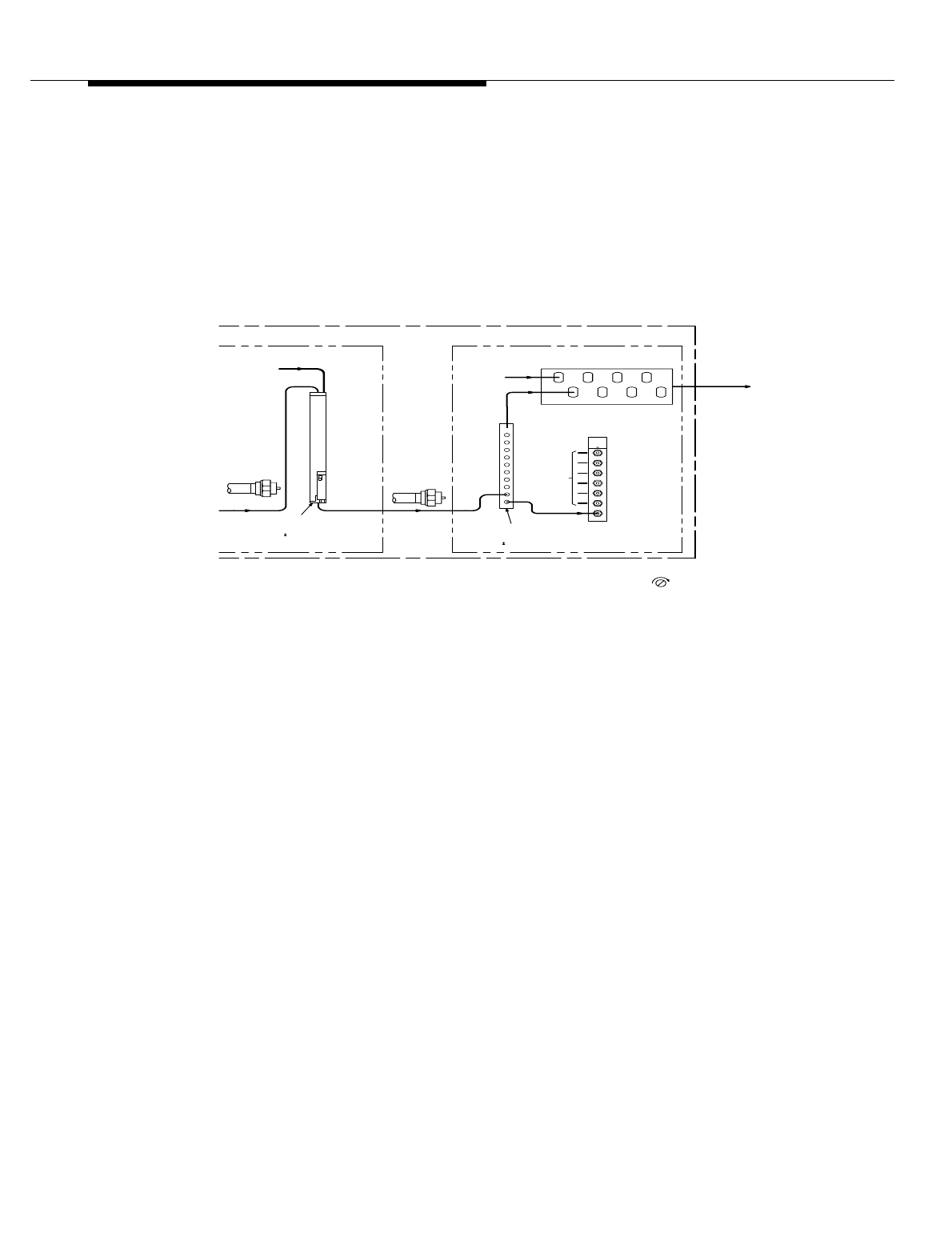
Lucent Technologies — Proprietary
See notice on first page
12-8 401-660-100 Issue 11 August 2000
Routine Maintenance and Radio Performance Tests
At data terminal keyboard:
Enter RMV:CELL a,RA b
Where: a = Cell Site number (1-222)
b = RCU number (0-191)
Enter DGN:CELL a,RA b
Response: ATP and then ALL TEST PASS
Figure 12-1. Voice Channel Test Paths
Loss
Cable
(-16
-.3 to -.6 dB
BBN2
RCUs on Shelf
From Other
"A"
AT&T
Combiner
Transmit
.5 dB Loss)
"A"
A12
Ports
Ports
A1 thru
(Sheet 2)
Amplifier
Linear
Frame
To
Jacks
Monitoring
6
5
4
Transmit
3
2
1
531
642
Tx
0
SET UP
from Frame
Total RF OUT
0
MON.
Tx SIG
(Xcelite RS3322 or equivalent)
Adjustments require small screwdriver
ble. Release 4.1 makes available a 6-Sector Configuration. The sequence in which each Radio
wn in Figure 2-6.
logged on a Reference Chart at installation - See Reference Chart, Sheet 3. For Release 4.0 OMNI
s fixed and is not an option. The way each output "A" port cable (A16, A18, A20) is connected to the
ouped in groups of four and the RF outputs from each group are wired to an input "A" port on the
A16, A18, A20
Loss
Cable
Tx SIG MON
.5 dB Loss)(-10.5
1:9
J1
BBP-1
Combiner
(See Note 1 Below)
Interconnection Panel Assembly
RF OUT
from Other
1:9 Combiners
RF OUT
J3
-.3 to -1.2 dB
1:9 Combiners
From Other
J6
J5
J4
J9
J8
J7
J11
J10
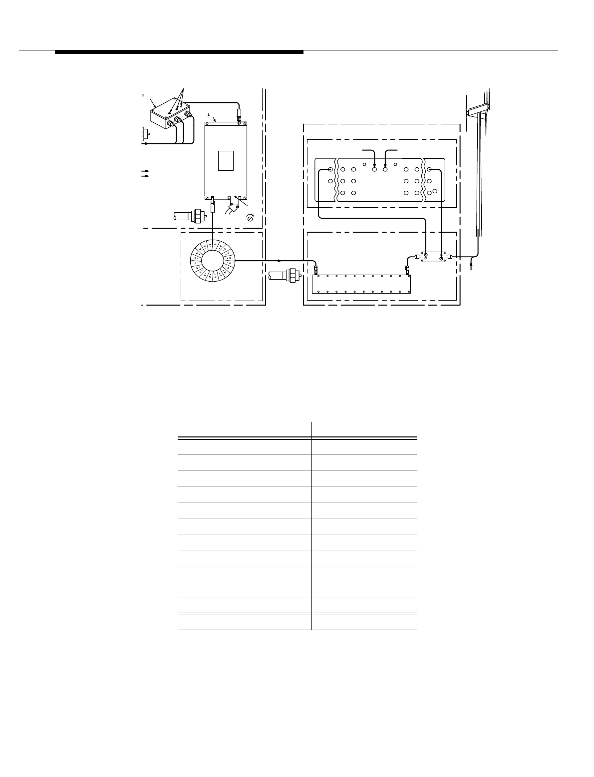
Lucent Technologies — Proprietary
See notice on first page
401-660-100 Issue 11 August 2000 12-9
Routine Maintenance and Radio Performance Tests
Figure 12-2. Voice Channel Test Paths
Cable Loss
Measurement 1. Configure the IFR FM/AM 1500 Communications Service Monitor (CSM)
as shown in Table 12-2 and allow 30 minutes warm-up:
J40
J20J25
J45
Filter Panels
Transmit
From Other
J60J65
-40 dB
-50 dB
Coupler
Directional
Reflected Test Port
J2J1
Control Interface
Transmit
J66
J46
J26
J4J3
J36
J56
J16
Transmit Filter
A maximum of seven antennas may be driven per cell site-OMNI,
For each Linear Amplifier unit there is one preamplifier and one 3:1 Combiner.
f 720 watts. This gives a total RF output
ts - 240 watts per Linear Amplifier Circuits.
me can have up to four Linear Amplifier
Frame can have up to three Linear The Antenna Interface Frame may use up to seven Transmit Filter
rames and Antenna Interface Frames
Panels. Duplex Panels may be used.
3-Sector, or some combination of OMNI and 3-Sector.
n Antenna Configuration and Power Output.
J41660CA-1
Linear Amplifier Unit - LAU0
(See Note 2 Below)
Loss
As Required
Cable
-.4 to -1.1 dB
Unit PAO
To Other 3:1 Combiners -
(+35
biner PDO
3 dB Loss)
5 dB Gain)
* Preamplifier
Antenna Interface Frame
Gain ADJ
Radio Test Unit Switch Panel
Forward Test Port
J35
J55
J15
J50
J30
J10
Loss
Cable
Transmit Filter Panel
-5 dB
Table 12-2. Configuration of IFR FM/AM 1500 CSM
ATTENUATOR 0 dB
DISPLAY ANALY
ANALY DISPR 1M
DUPLEX/SIMPLEX DUPLEX
GEN/REC GEN
AVE PEAK/PEAK AVG PEAK
MODULATION FM3
DEV-PWR 20 kHz
DEV-VERT 5 kHz/DIV
dB/DIV 10
GEN/LOCK FULLY CCW
INT TONE/RCVR RCVR
VOLUME AS DESIRED

Lucent Technologies — Proprietary
See notice on first page
12-10 401-660-100 Issue 11 August 2000
Routine Maintenance and Radio Performance Tests
2. Press Enter on the keyboard.
3. Press RF on the keyboard. Enter 8803200, press Enter on the keyboard.
Confirm 880.3200 MHz is displayed.
NOTE:
For non-wireline company, use 875.0100 MHz.
4. Connect a reference cable from the DUPLEX OUTPUT jack to the
ANTENNA jack.
5. The signal should appear near the -40 graticule level. Set the dB/DIV
switch to 1 and use the VERT POS control to adjust the reference level so
that the peak of the signal is at the -40 graticule level. (After this is done, do
not adjust the VERT POS control for any reason while performing the
alignment and measurements, otherwise inaccuracies occur.)
6. Disconnect the reference cable from the ANTENNA jack.
7. Connect the test cable and any associated adapters whose loss is to be
measured to the ANTENNA jack. Connect the reference cable and the test
cable to be measured together using a BNC jack/BNC jack adapter.
8. Read the Radio Frequency (RF) output level at the Cathode Ray Tube
(CRT). The loss of the test cable is the difference between the measured
output level and the reference level (measured output level minus -40
dBm). Retain this value for subsequent use.
9. In the Cell Site Log or in translations, look up the Radio Channel Unit
(RCU) number (0 to 199), assigned channel number, and assigned
frequency of the RCU to be tested.
10. If test is to be run from the Cell Site, establish a Cell Site/MSC data link
(see procedure covering Cell Site to Mobile Switching Center (MSC) data
link).
11. Configure the IFR FM/AM 1500 Communications Service Monitor (CSM)
as follows:
12. Remove the 50-ohm terminator from J3 (Incident Port) on the Radio Test
Unit (RTU) switch panel on the Antenna Interface Frame (AIF).
SQUELCH FULLY CCW
FREQ ERROR 1 kHz
RF OUTPUT LEVEL −40 dBm
Table 12-2. Configuration of IFR FM/AM 1500 CSM (Contd)
ATTENUATOR 0 dB

Lucent Technologies — Proprietary
See notice on first page
401-660-100 Issue 11 August 2000 12-11
Routine Maintenance and Radio Performance Tests
13. Connect the test cable with a known loss to J3 (Incident Port) on the RTU
switch panel on the AIF, using a BNC jack/SMA plug adapter. Connect the
other end of the test cable to Communications Service Monitor (CSM) as
follows:
14. Tests performed are measurements of transmitter frequency, power output,
and frequency deviation on the Voice Radio Channel Units (V-RCUs).
Frequency deviation measurements are made for voice, Supervisory Audio
Tone (SAT), and data transmissions.
15. All measurements are made at J3 on the RTU switch panel.
16. Effective Radiated Power (ERP) is calculated for the Radio Channel Unit
(RCU) under test as a function of the power level at J3.
17. All measurements taken are recorded along with the serial number and
calibration date of the test equipment used to perform the tests.
18. The value of the power input to the antenna (input from the foam jumper
cable) should be the same for all RCUs connected to the same antenna.
19. The maximum allowable Federal Communications Commission's (FCC's)
ERP is 500 watts per channel.
Table 12-3. Configuration of IFR FM/AM 1500 CDM
CONTROL SET TO
DISPLAY METER
ATTENUATOR 40 dB
AVG PEAK/PEAK PEAK
MODULATION FM3
DEV-PWR 15
FREQ ERROR 1 kHz
ANALY DISPR 10 kHz/DIV
DEV-VERT 5 kHz/DEV
dB/DIV 10
GEN/LOCK LOCK
INT TONE/RCVR RCVR
VOLUME As desired
SQUELCH FULLY CCW
GEN/REC REC
DUPLEX/SIMPLEX SIMPLEX

Lucent Technologies — Proprietary
See notice on first page
12-12 401-660-100 Issue 11 August 2000
Routine Maintenance and Radio Performance Tests
20. On the CSM, press RF and enter the assigned Radio Frequency (RF) of
the RCU under test.
21. Frequency Measurement
22. At data terminal keyboard:
Enter CFR:CELL a,RA n; START
Response: ALL WENT WELL
Where: a = Cell Site number (1-222)
n = RCU number (0-191)
Enter CFR:CELL a,RA n; CONFIG 150
Response: ALL WENT WELL
Enter CFR:CELL a,RA n; XMITC 300
Response: ALL WENT WELL
Enter CFR:CELL a,RA n; VRADPC 357
Response: ALL WENT WELL
23. Read the frequency error on the Cathode Ray Tube's (CRT's)
Communications Service Monitor (CSM) display.
NOTE:
If frequency error is small, increase resolution by changing FRQ ERROR to
300 or 100 Hz scale.
24. Is measured frequency less than ± 0.80 kHz?
If YES, then record in Cell Site Log and continue to Step 25 for power
measurement. If No, then continue to Step 24.
25. Replace the Radio Channel Unit (RCU) and repeat this procedure.
Power
Measurement 26. At Communications Service Monitor (CSM), set DISPLAY to ANALY
.
27. Read RF level (to the nearest dB) from the center of the Cathode Ray Tube
(CRT) Communications Service Monitor (CSM) display.
28. Calculate the power level at J3 (Incident Port) by adding the Test Cable
Loss (in dB) to the measured power level above.
29. The level obtained in Step 27 should equal the level recorded in the Cell
Site Log (± x dBm) for the LAC associated with the Radio Channel Unit
(RCU) under test. Adjust the RCU output until the correct level is obtained.
30. If the RCU under test is an existing RCU or the replacement for an existing
RCU, the values recorded in columns 1 through 7 of the Cell Site log are
valid.
31. If the RCU is being put into service for the first time, the values to be
recorded in columns 1 through 7 are the same as other RCUs on the same
Linear Amplifier Circuit (LAC).

Lucent Technologies — Proprietary
See notice on first page
401-660-100 Issue 11 August 2000 12-13
Routine Maintenance and Radio Performance Tests
NOTE:
If the RCU under test is a setup RCU, go to Step 48.
Voice 1004 Hz
Deviation
Measurement
32. At data terminal keyboard:
Enter CFR:CELL a,RA n; BASEB 106
Response: ALL WENT WELL
Enter CFR:CELL a,RA n; BASEB 101
Response: ALL WENT WELL
33. At the Communications Service Monitor (CSM) display set DISPLAY to
METER, MODULATION to FM2, and DEV to 6 kHz.
34. From the Cathode Ray Tube (CRT) display of the Communications Service
Monitor (CSM), read DEV in kHz
35. Is measured peak frequency deviation within the limits shown in Table
12-4?
Table 12-4. Peak Frequency Deviation Limits
Network
Transmission Peak Frequency Deviation (kHz)
Level –TX (dB)* Nominal Lower Limit Upper Limit
+3 5.47 4.99 5.95
+2 5.16 4.71 5.61
+1 4.87 4.45 5.32
0 4.60 4.20 5.00
–1 4.34 3.96 4.72
–2 4.10 3.74 4.46
–3 3.87 3.53 4.21
–4 3.65 3.33 3.97
–5 3.45 3.15 3.75
–6 3.26 2.98 3.54
–7 3.07 2.80 3.34
–8 2.90 2.65 3.15
–9 2.74 2.50 2.98
–10 2.59 2.36 2.82
–11 2.44 2.23 2.65
–12 2.31 2.11 2.51
–13 2.18 1.99 2.37

Lucent Technologies — Proprietary
See notice on first page
12-14 401-660-100 Issue 11 August 2000
Routine Maintenance and Radio Performance Tests
If YES, then record in Cell Site Log as PEAK FREQUENCY DEVIATION
DUE TO 1004 Hz MODULATION AT -16 dBm and do Step 36. If NO, then
continue to Step 35.
36. Replace the Radio Channel Unit (RCU) and repeat this procedure.
37. At data terminal keyboard:
Enter CFR:CELL a,RA n; BASEB 102
Response: ALL WENT WELL
Enter CFR:CELL a,RA n; BASEB 100
Response: ALL WENT WELL
38. At CSM, set DEV-PWR to 20 kHz.
39. From Cathode Ray Tube (CRT) of CSM, read DEV in kHz.
40. Is measured peak frequency deviation less than or equal to the 12 kHz
maximum limit?
If YES, then record in Log as PEAK FREQUENCY DEVIATION DUE TO
1004 Hz MODULATION AT 0 dBm and do Step 41. If NO, then continue to
Step 40.
41. Replace the Radio Channel Unit (RCU) and repeat this procedure.
42. At data terminal keyboard:
Enter CFR:CELL a,RA n; BASEB 102
Response: ALL WENT WELL
43. At data terminal keyboard:
Enter CFR:CELL a,RA n; BASEB 112
Response: ALL WENT WELL
44. At CSM, set DEV-PWR to 6 kHz.
45. From CRT of CSM, read DEV in kHz.
46. Is measured peak frequency deviation within the 1.75 to 2.25 kHz limits?
–14 2.05 1.87 2.23
–15 1.94 1.77 2.11
.*The Network Transmission Level - TX 9 (dB) is
the value located in the Cell Site data base, cell dB,
"Network Transmission Level - TX" in the RC/V
(Recent Change & Verify) subsystem.
Table 12-4. Peak Frequency Deviation Limits (Contd)
Network
Transmission Peak Frequency Deviation (kHz)

Lucent Technologies — Proprietary
See notice on first page
401-660-100 Issue 11 August 2000 12-15
Routine Maintenance and Radio Performance Tests
If YES, then record in Log as PEAK FREQUENCY DEVIATION DUE TO
SAT and do Step 47. If NO, then continue to Step 46.
47. Replace the Radio Channel Unit (RCU) and repeat this procedure.
48. At data terminal keyboard:
Enter CFR:CELL a,RA n; BASEB 113
Response: ALL WENT WELL
Data 10 kHz Deviation Measurement
49. At data terminal keyboard:
Enter CFR:CELL a,RA n; ECODC 201
Response: ALL WENT WELL
50. At the Communications Service Monitor (CSM), set DEV/PWR to 20 kHz
and MODULATION to FM3.
51. Is measured peak frequency deviation within 7.0 to 9.0 kHz limits?
If YES, then record in Cell Site Log as PEAK FREQUENCY DEVIATION
DUE TO 10 kHz and do Step 52. If NO, then continue to Step 51.
52. Replace the Radio Channel Unit (RCU) and repeat this procedure.
53. Remove transmission test set from J3.
54. At data terminal keyboard:
Enter CFR:CELL a,RA n; ECODC 202
Response: ALL WENT WELL
Enter STOP:DGN;CELL a,RA n
Response: OOS, MANUAL, RMVD
Enter RST:CELL a,RA n
NOTE:
This procedure must be repeated for each voice channel to be tested.
55. Is this the last voice channel to be tested?
If YES, then continue to Step 55. If NO, then go to Pretest.
Post Test
Procedure 56. In Cell Site Log, record test equipment model, serial number, and
calibration date. Record Federal Communications Commission (FCC) radio
telephone license number, its expiration date, the date of test, and then
sign the Log.
57. Remove and store all test equipment and test cables.
58. STOP. YOU HAVE COMPLETED THIS PROCEDURE.

Lucent Technologies — Proprietary
See notice on first page
12-16 401-660-100 Issue 11 August 2000
Routine Maintenance and Radio Performance Tests
Transmitter
Output Power
Verification
NOTE:
Output power is measured at jack J3 on the Radio Test Unit (RTU) switch
panel.
1. Verify that the cell's Radio Channel Unit (RCU) equipage per transmitter
[Linear Amplifier Circuit (LAC)] agrees with the Cell Site Test Record
Sheets. Update the sheets with the added Digital Radio Units (DRUs).
2. Specify and verify that the DRU output power is different from the RCU.
NOTE:
When determining the maximum number of radios that are assigned to a
LAC, each DRU should be counted as 1.5 units, and each RCU should be
counted as 1.0 units. Ensure that the units added to each transmitter (LAC)
does not exceed the LAC's maximum allowable output power.
1. If the Cell Site Test Record Sheet is inaccurate or missing, verify that the
transmitter's (LAC) maximum allowable output power is not exceeded.
Transmitter
Output Power
Adjustment
2. 1. Connect a test cable of known loss between the CSTS RF IN/OUT jack
and jack J3 on the RTU switch panel.
NOTE:
The CSTS is operated in the manual mode during this subsection.
3. On the CSTS at the Lucent TESTS menu, press EXIT to set the CSTS to
the manual mode. While in the manual mode, perform the following
procedures:
a. Press RESET.
b. Select and punch TO SCREEN - SPEC ANL.
c. Select and punch CENTER FREQ.
d. Enter 882 via the DATA keys, and press ENTER.
e. Select and punch REF LEVEL.
f. Enter -10 via the DATA keys, and press ENTER.
g. Select and punch SPAN.
h. Enter 30 via the DATA keys, and press ENTER.
i. Select and punch CONTROLS - MAIN.
j. Under CHOICES, select and punch AUXILIARY.
k. Select and punch CONTROLS - NO PK/AVG.
l. Under CHOICES, select and punch AVG 10.

Lucent Technologies — Proprietary
See notice on first page
401-660-100 Issue 11 August 2000 12-17
Routine Maintenance and Radio Performance Tests
4. Enter the value of the RF IN/OUT test cable's loss into the CSTS as
follows:
a. Press SHIFT.
b. Press DUPLEX.
c. Select and punch CONFIGURE - RF LEVEL OFFSET. (ON should
be underscored.)
d. Select and punch CONFIGURE - RF IN/OUT.
e. Enter the value of the test cable's loss (as a negative number) via
the DATA keys, and press ENTER.
f. Press PREV.
5. Choose an AMPS RCU that is assigned to the same transmitter (LAC) as
that of the DRU under test.
NOTE:
The RCU is used as a reference radio for the DRU under test. Choose an
RCU that is set to the same full power level value (0 VRAL) to that in which
the DRU under test will be adjusted.
6. Configure the reference RCU under test for full power output as follows:
NOTE:
After each MSC command input, wait for the MSC response message: ALL
WENT WELL.
RMV:CELL x,RA y;UCL (where x=cell number; y=radio number)
CFR:CELL x,RA y;START
CFR:CELL x,RA y;CONFIG 150
CFR:CELL x,RA y;XMITC 300
CFR:CELL x,RA y;VRADPC 357
7. Configure the RCU under test for full power output as follows: After each
MSC command input, wait for the MSC response message: ALL WENT
WELL.
RMV:CELL x,RA y;UCL (where x=cell number; y=radio number)
CFR:CELL x,RA y;START
CFR:CELL x,RA y;CONFIG 150
CFR:CELL x,RA y;XMITC 300
CFR:CELL x,RA y;VRADPC 357
8. Ensure that the DRU under test's AUTO/OFF switch is set to AUTO.
9. Identify the reference RCU and the DRU under test on the CSTS's display.

Lucent Technologies — Proprietary
See notice on first page
12-18 401-660-100 Issue 11 August 2000
Routine Maintenance and Radio Performance Tests
NOTE:
If multiple radios are in service, their signals will also be present on the
display. Momentarily set the RCU's and/or DRU's AUTO/OFF switch to OFF
to help to identify the signals.
10. On the Lucent CSTS, perform the following procedures:
a. Select and punch CONTROLS - AUXILIARY.
b. Under CHOICES, select and punch MARKER.
c. Select and punch MARKER TO - NEXT PEAK multiple times until
the display's marker is positioned on the peak of the reference
RCU's signal.
d. Record the MARKER LVL (dbm) as displayed on the CSTS's display
(upper right corner).
e. Select and punch MARKER TO - NEXT PEAK multiple times until
the display's marker is positioned on the peak of the DRU under
test's signal.
11. Slowly adjust the potentiometer on the front of the DRU under test until the
DRU's signal level matches the reference RCU's level as displayed by
MARKER LVL.
NOTE:
Because of the video averaging effect, the CSTS's response to adjusting
the DRU's level is delayed. To improve the response, press MEAS RESET
during the measurement.
12. Set the DRU under test's AUTO/OFF switch to OFF.
13. Repeat Step 6 through Step 12 under the Transmitter Output Power
Adjustment section for all other newly installed DRUs that are assigned to
the transmitter (LAC) under test.
14. Terminate the reference RCU as follows:
STOP:CFR;CELL X,RA Y (where X=cell number; Y=radio number)
RST:CELL X,RA Y;UCL

Lucent Technologies — Proprietary
See notice on first page
401-660-100 Issue 11 August 2000 12-19
Routine Maintenance and Radio Performance Tests
Table 12-5. Channel Number Center Frequencies
Channel
Number Center Freq(MHz)
Cell Site Subscriber Channel
Number Center Freq (MHz) Cell
Site Subscriber
1 870.030 825.030 44 871.320 826.320
2 870.060 825.060 45 871.350 826.350
3 870.090 825.090 46 871.380 826.380
4 870.120 825.120 47 871.410 826.410
5 870.150 825.150 48 871.440 826.440
6 870.180 825.180 49 871.470 826.470
7 870.210 825.210 50 871.500 826.500
8 870.240 825.240 51 871.530 826.530
9 870.270 825.270 52 871.560 826.560
10 870.300 825.300 53 871.590 826.590
11 870.330 825.330 54 871.620 826.620
12 870.360 825.360 55 871.650 826.650
13 870.390 825.390 56 871.680 826.680
14 870.420 825.420 57 871.710 826.710
15 870.450 825.450 58 871.740 826.740
16 870.480 825.480 59 871.770 826.770
17 870.510 825.510 60 871.800 826.800
18 870.540 825.540 61 871.830 826.830
19 870.570 825.570 62 871.860 826.860
20 870.600 825.600 63 871.890 826.890
21 870.630 825.630 64 871.920 826.920
22 870.660 825.660 65 871.950 826.950
23 870.690 825.690 66 871.980 826.980
24 870.720 825.720 67 872.010 827.010
25 870.750 825.750 68 872.040 827.040
26 870.780 825.780 69 872.070 827.070
27 870.810 825.810 70 872.100 827.100

Lucent Technologies — Proprietary
See notice on first page
12-20 401-660-100 Issue 11 August 2000
Routine Maintenance and Radio Performance Tests
28 870.840 825.840 71 872.130 827.130
29 870.870 825.870 72 872.160 827.160
30 870.900 825.900 73 872.190 827.190
31 870.930 825.930 74 872.220 827.220
32 870.960 825.960 75 872.250 827.250
33 870.990 825.990 76 872.280 827.280
34 871.020 826.020 77 872.310 827.310
35 871.050 826.050 78 872.340 827.340
36 871.080 826.080 79 872.370 827.370
37 871.110 826.110 80 872.400 827.400
38 871.140 826.140 81 872.430 827.430
39 871.170 826.170 82 872.460 827.460
40 871.200 826.200 83 872.490 827.490
41 871.230 826.230 84 872.520 827.520
42 871.260 826.260 85 872.550 827.550
43 871.290 826.290 86 872.580 827.580
87 872.610 827.610 129 873.870 828.870
88 872.640 827.640 130 873.900 828.900
89 872.670 827.670 131 873.930 828.930
90 872.700 827.700 132 873.960 828.960
91 872.730 827.730 133 873.990 828.990
92 872.760 827.760 134 874.020 829.020
93 872.790 827.790 135 874.050 829.050
94 872.820 827.820 136 874.080 829.080
95 872.850 827.850 137 874.110 829.110
96 872.880 827.880 138 874.140 829.140
97 872.910 827.910 139 874.170 829.170
Table 12-5. Channel Number Center Frequencies (Contd)
Channel
Number Center Freq(MHz)
Cell Site Subscriber Channel
Number Center Freq (MHz) Cell
Site Subscriber

Lucent Technologies — Proprietary
See notice on first page
401-660-100 Issue 11 August 2000 12-21
Routine Maintenance and Radio Performance Tests
98 872.940 827.940 140 874.200 829.200
99 872.970 827.970 141 874.230 829.230
100 873.000 828.000 142 874.260 829.260
101 873.030 828.030 143 874.290 829.290
102 873.060 828.060 144 874.320 829.320
103 873.090 828.090 145 874.350 829.350
104 873.120 828.120 146 874.380 829.380
105 873.150 828.150 147 874.410 829.410
106 873.180 828.180 148 874.440 829.440
107 873.210 828.210 149 874.470 829.470
108 873.240 828.240 150 874.500 829.500
109 873.270 828.270 151 874.530 829.530
110 873.300 828.300 152 874.560 829.560
111 873.330 828.330 153 874.590 829.590
112 873.360 828.360 154 874.620 829.620
113 873.390 828.390 155 874.650 829.650
114 873.420 828.420 156 874.680 829.680
115 873.450 828.450 157 874.710 829.710
116 873.480 628.480 158 874.740 829.740
117 873.510 828.510 159 874.770 829.770
118 873.540 828.540 160 874.800 829.800
119 873.570 828.570 161 874.830 829.830
120 873.600 828.600 162 874.860 829.860
121 873.630 828.630 163 874.890 829.890
122 873.660 828.660 164 874.920 829.920
123 873.690 828.690 165 874.950 829.950
124 873.720 828.720 166 874.980 829.980
Table 12-5. Channel Number Center Frequencies (Contd)
Channel
Number Center Freq(MHz)
Cell Site Subscriber Channel
Number Center Freq (MHz) Cell
Site Subscriber

Lucent Technologies — Proprietary
See notice on first page
12-22 401-660-100 Issue 11 August 2000
Routine Maintenance and Radio Performance Tests
125 873.750 828.750 167 875.010 830.010
126 873.780 828.780 168 875.040 830.040
127 873.810 828.810 169 875.070 830.070
128 873.840 828.640 170 875.100 830.100
171 875.130 830.130 214 876.420 831.420
172 875.160 830.160 215 876.450 831.450
173 875.190 830.190 216 876.480 831.480
174 875.220 830.220 217 876.510 831.510
175 875.250 830.250 218 876.540 831.540
176 875.280 830.280 219 876.570 831.570
177 875.310 830.310 220 876.600 831.600
178 875.340 830.340 221 876.630 831.630
179 875.370 830.370 222 876.660 831.660
180 875.400 830.400 223 876.690 831.690
181 875.430 830.430 224 876.720 831.720
182 875.460 830.460 225 876.750 831.750
183 875.490 830.490 226 876.780 831.780
184 875.520 830.520 227 876.810 831.810
185 875.550 830.550 228 876.840 831.840
186 875.580 830.580 229 876.870 831.870
187 875.610 830.610 230 876.900 831.900
188 875.640 830.640 231 876.930 831.930
189 875.670 830.670 232 876.960 831.960
190 875.700 830.700 233 876.990 831.990
191 875.730 830.730 234 877.020 832.020
192 875.760 830.760 235 877.050 832.050
193 875.790 830.790 236 877.080 832.080
Table 12-5. Channel Number Center Frequencies (Contd)
Channel
Number Center Freq(MHz)
Cell Site Subscriber Channel
Number Center Freq (MHz) Cell
Site Subscriber

Lucent Technologies — Proprietary
See notice on first page
401-660-100 Issue 11 August 2000 12-23
Routine Maintenance and Radio Performance Tests
194 875.820 830.820 237 877.110 832.110
195 875.850 830.850 238 877.140 832.140
196 875.880 830.880 239 877.170 832.170
197 875.910 830.910 240 877.200 832.200
198 875.940 830.940 241 877.230 832.230
199 875.970 830.970 242 877.260 832.260
200 876.000 831.000 243 877.290 832.290
201 876.030 831.030 244 877.320 832.320
202 876.060 831.060 245 877.350 832.350
203 876.090 831.090 246 877.380 832.380
204 876.120 831.120 247 877.410 832.410
205 876.150 831.150 248 877.440 832.440
206 876.180 831.180 249 877.470 832.470
207 876.210 831.210 250 877.500 832.500
208 876.240 831.240 251 877.530 832.530
209 876.270 831.270 252 877.560 832.560
210 876.300 831.300 253 877.590 832.590
211 876.330 831.330 254 877.620 832.620
212 876.360 831.360 255 877.650 832.650
213 876.390 831.390 256 877.680 832.680
257 877.710 832.710 300 879.000 834.000
258 877.740 832.740 301 879.030 834.030
259 877.770 832.770 302 879.060 834.060
260 877.800 832.800 303 879.090 834.090
261 877.830 832.830 304 879.120 834.120
262 877.860 832.860 305 879.150 834.150
263 877.890 832.890 306 879.180 834.180
Table 12-5. Channel Number Center Frequencies (Contd)
Channel
Number Center Freq(MHz)
Cell Site Subscriber Channel
Number Center Freq (MHz) Cell
Site Subscriber

Lucent Technologies — Proprietary
See notice on first page
12-24 401-660-100 Issue 11 August 2000
Routine Maintenance and Radio Performance Tests
264 877.920 832.920 307 879.210 834.210
265 877.950 832.950 308 879.240 834.240
266 877.980 832.980 309 879.270 834.270
267 878.010 833.010 310 879.300 834.300
268 878.040 833.040 311 879.330 834.330
269 878.070 833.070 312 879.360 834.360
270 878.100 833.100 313 879.390 834.390
271 878.130 833.130 314 879.420 834.420
272 878.160 833.160 315 879.450 834.450
273 878.190 833.190 316 879.480 834.480
274 878.220 833.220 317 879.510 834.510
275 878.250 833.250 318 879.540 834.540
276 878.280 833.280 319 879.570 834.570
277 878.310 833.310 320 879.600 834.600
278 878.340 833.340 321 879.630 834.630
279 878.370 833.370 322 879.660 834.660
280 878.400 833.400 323 879.690 834.690
281 878.430 833.430 324 879.720 834.720
282 878.460 833.460 325 879.750 834.750
283 878.490 833.490 326 879.780 834.780
284 878.520 833.520 327 879.810 834.810
285 878.550 833.550 328 879.840 834.840
286 878.580 833.580 329 879.870 834.870
287 878.610 833.610 330 879.900 834.900
288 878.640 833.640 331 879.930 834.930
289 878.670 833.670 332 879.960 834.960
290 878.700 833.700 333 879.990 834.990
Table 12-5. Channel Number Center Frequencies (Contd)
Channel
Number Center Freq(MHz)
Cell Site Subscriber Channel
Number Center Freq (MHz) Cell
Site Subscriber

Lucent Technologies — Proprietary
See notice on first page
401-660-100 Issue 11 August 2000 12-25
Routine Maintenance and Radio Performance Tests
291 878.730 833.730 334 880.020 835.020
292 878.760 833.760 335 880.050 835.050
293 878.790 833.790 336 880.080 835.080
294 878.820 833.820 337 880.110 835.110
295 878.850 833.850 338 880.140 835.140
296 878.880 833.880 339 880.170 835.170
297 878.910 833.910 340 880.200 835.200
298 878.940 833.940 341 880.230 835.230
299 878.970 833.970 342 880.260 835.260
343 880.290 835.290 385 881.550 836.550
344 880.320 835.320 386 881.580 836.580
345 880.350 835.350 387 881.610 836.610
346 880.380 835.380 388 881.640 836.640
347 880.410 835.410 389 881.670 836.670
348 880.440 835.440 390 881.700 836.700
349 880.470 835.470 391 881.730 836.730
350 880.500 835.500 392 881.760 836.760
351 880.530 835.530 393 881.790 836.790
352 880.560 835.560 394 881.820 836.820
353 880.590 835.590 395 881.850 836.850
354 880.620 835.620 396 881.880 836.880
355 880.650 835.650 397 881.910 836.910
356 880.680 835.660 398 881.940 836.940
357 880.710 835.710 399 881.970 836.970
358 880.740 835.740 400 882.000 837.000
359 880.770 835.770 401 882.030 837.030
360 880.800 835.800 402 882.060 837.060
Table 12-5. Channel Number Center Frequencies (Contd)
Channel
Number Center Freq(MHz)
Cell Site Subscriber Channel
Number Center Freq (MHz) Cell
Site Subscriber

Lucent Technologies — Proprietary
See notice on first page
12-26 401-660-100 Issue 11 August 2000
Routine Maintenance and Radio Performance Tests
361 880.830 835.830 403 882.090 837.090
362 880.860 835.860 404 882.120 837.120
363 880.890 835.890 405 882.150 837.150
364 880.920 835.920 406 882.180 837.180
365 880.950 835.950 407 882.210 837.210
366 880.980 835.980 408 882.240 837.240
367 881.010 836.010 409 882.270 837.270
368 881.040 836.040 410 882.300 837.300
369 881.070 836.070 411 882.330 837.330
370 881.100 836.100 412 882.360 837.360
371 881.130 836.130 413 882.390 837.390
372 881.160 836.160 414 882.420 837.420
373 881.190 836.190 415 882.450 837.450
374 881.220 836.220 416 882.480 837.480
375 881.250 836.250 417 882.510 837.510
376 881.280 836.280 418 882.540 837.540
377 881.310 836.310 419 882.570 837.570
378 881.340 836.340 420 882.600 837.600
379 881.370 836.370 421 882.630 837.630
380 881.400 836.400 422 882.660 837.660
381 881.430 836.430 423 882.690 837.690
382 881.460 836.460 424 882.720 837.720
383 881.490 836.490 425 882.750 837.750
384 881.520 836.520 426 882.780 837.780
427 882.810 837.810 469 884.070 839.070
428 882.840 837.840 470 884.100 839.100
429 882.870 837.870 471 884.130 839.130
Table 12-5. Channel Number Center Frequencies (Contd)
Channel
Number Center Freq(MHz)
Cell Site Subscriber Channel
Number Center Freq (MHz) Cell
Site Subscriber

Lucent Technologies — Proprietary
See notice on first page
401-660-100 Issue 11 August 2000 12-27
Routine Maintenance and Radio Performance Tests
430 882.900 837.900 472 884.160 839.160
431 882.930 837.930 473 884.190 839.190
432 882.960 837.960 474 884.220 839.220
433 882.990 837.990 475 884.250 839.250
434 883.020 837.020 476 884.280 839.280
435 883.050 838.050 477 884.310 839.310
436 883.080 838.080 478 884.340 839.340
437 883.110 838.110 479 884.370 839.370
438 883.140 838.140 480 884.400 839.400
439 883.170 838.170 481 884.430 839.430
440 883.200 838.200 482 884.460 839.460
441 883.230 838.230 483 884.490 839.490
442 883.260 838.260 484 884.520 839.520
443 883.290 838.290 485 884.550 839.550
444 883.320 838.320 486 884.580 839.580
445 883.350 838.350 487 884.610 839.610
446 883.380 838.380 488 884.640 839.640
447 883.410 838.410 489 884.670 839.670
448 883.440 838.440 490 884.700 839.700
449 883.470 838.470 491 884.730 839.730
450 883.500 838.500 492 884.760 839.760
451 883.530 838.530 493 884.790 839.790
452 883.560 838.560 494 884.029 839.820
453 883.590 838.590 495 884.850 839.850
454 883.620 838.620 496 884.880 839.880
455 883.650 838.650 497 884.910 839.910
456 883.680 838.680 498 884.940 839.940
Table 12-5. Channel Number Center Frequencies (Contd)
Channel
Number Center Freq(MHz)
Cell Site Subscriber Channel
Number Center Freq (MHz) Cell
Site Subscriber

Lucent Technologies — Proprietary
See notice on first page
12-28 401-660-100 Issue 11 August 2000
Routine Maintenance and Radio Performance Tests
457 883.710 838.710 499 884.910 839.970
458 883.740 838.740 500 885.300 840.000
459 883.770 838.770 501 885.030 840.030
460 883.800 838.800 502 885.060 840.060
461 883.830 838.830 503 885.090 840.090
462 883.860 838.860 504 885.120 840.120
463 883.890 838.890 505 885.150 840.150
464 883.920 838.920 506 885.180 840.180
465 883.950 838.950 507 885.210 840.210
466 883.980 838.980 508 885.240 840.240
467 884.010 839.010 509 885.270 840.270
468 864.040 839.040 510 885.300 840.300
511 885.330 840.330 553 886.590 841.590
512 885.360 840.360 554 886.620 841.620
513 885.390 840.390 555 886.650 841.650
514 885.420 840.420 556 886.680 841.680
515 885.450 840.450 557 886.710 841.710
516 885.480 840.480 558 886.740 841.740
517 885.510 840.510 559 886.770 841.770
518 885.540 840.540 560 886.800 841.800
519 885.570 840.570 561 886.630 841.830
520 885.600 840.600 562 886.860 841.860
521 885.630 840.630 563 886.890 841.890
522 885.660 840.660 564 886.920 841.920
523 885.690 840.690 565 886.950 841.950
524 685.720 840.720 566 886.980 841.980
525 885.750 840.750 567 887.010 842.010
Table 12-5. Channel Number Center Frequencies (Contd)
Channel
Number Center Freq(MHz)
Cell Site Subscriber Channel
Number Center Freq (MHz) Cell
Site Subscriber

Lucent Technologies — Proprietary
See notice on first page
401-660-100 Issue 11 August 2000 12-29
Routine Maintenance and Radio Performance Tests
526 885.780 840.780 568 887.040 842.040
527 885.810 840.810 569 887.070 842.070
528 885.840 840.840 570 887.100 842.100
529 885.870 840.870 571 887.130 842.130
530 885.900 840.900 572 887.160 842.160
531 885.930 840.930 573 887.190 842.190
532 885.960 840.960 574 887.220 842.220
533 885.990 840.990 575 887.250 842.250
534 886.020 841.020 576 887.280 842.280
535 886.050 841.050 577 887.310 842.310
536 886.080 841.080 578 887.340 842.340
537 886.110 841.110 579 887.370 842.370
538 886.140 841.140 580 887.400 842.400
539 886.170 841.170 581 887.430 842.430
540 886.200 841.200 582 887.460 842.460
541 886.230 841.230 583 887.490 842.490
542 886.260 841.260 584 887.520 842.520
543 886.290 841.290 585 887.550 842.550
544 886.320 841.320 586 887.580 842.580
545 886.350 841.350 587 887.610 842.610
546 886.380 841.380 588 887.640 842.640
547 886.410 841.410 589 887.670 842.670
548 886.440 841.440 590 887.700 842.700
549 886.470 841.470 591 887.730 842.730
550 886.500 841.500 592 887.760 842.760
551 886.530 841.530 593 887.790 842.790
552 886.560 841.560 594 887.820 842.820
Table 12-5. Channel Number Center Frequencies (Contd)
Channel
Number Center Freq(MHz)
Cell Site Subscriber Channel
Number Center Freq (MHz) Cell
Site Subscriber

Lucent Technologies — Proprietary
See notice on first page
12-30 401-660-100 Issue 11 August 2000
Routine Maintenance and Radio Performance Tests
595 887.850 842.850 636 889.080 844.080
596 887.880 842.880 637 889.110 844.110
597 887.910 842.910 638 889.140 844.140
598 887.940 842.940 639 889.170 844.170
599 887.970 842.970 640 889.200 844.200
600 888.000 843.000 641 889.230 844.230
601 886.030 843.030 642 889.260 844.260
602 888.060 843.060 643 889.290 844.290
603 888.090 843.090 644 889.320 844.320
604 888.120 843.120 645 889.350 844.350
605 888.150 843.150 646 889.380 844.380
606 888.180 843.180 647 889.410 844.410
607 888.210 843.210 648 889.440 844.440
608 888.240 843.240 649 889.470 844.470
609 888.270 843.270 650 889.500 844.500
610 888.300 843.300 651 889.530 844.530
611 888.330 843.330 652 889.560 844.560
612 888.360 843.360 653 889.590 844.590
613 888.390 843.390 654 889.620 844.620
614 888.420 843.420 655 889.650 844.650
615 888.450 843.450 656 889.680 844.680
616 888.480 843.480 657 889.710 844.710
617 888.510 843.510 658 889.740 844.740
618 888.540 843.540 659 889.770 844.770
619 886.570 843.570 660 889.800 844.800
620 888.600 843.600 661 889.830 844.830
621 888.630 843.630 662 869.860 844.860
Table 12-5. Channel Number Center Frequencies (Contd)
Channel
Number Center Freq(MHz)
Cell Site Subscriber Channel
Number Center Freq (MHz) Cell
Site Subscriber

Lucent Technologies — Proprietary
See notice on first page
401-660-100 Issue 11 August 2000 12-31
Routine Maintenance and Radio Performance Tests
622 888.660 843.660 663 689.890 844.890
623 886.690 843.690 664 889.920 844.920
624 888.720 843.720 665 889.950 844.950
625 888.750 843.750 666 689.980 844.980
626 888.780 843.780 667 890.010 845.010
627 888.810 843.810 668 890.040 845.040
628 888.840 843.840 669 890.070 845.070
629 888.870 843.870 670 890.100 845.100
630 888.900 843.900 671 890.130 845.130
631 888.930 843.930 672 890.160 845.160
632 888.960 843.960 673 890.190 845.190
633 888.990 843.990 674 890.220 845.220
634 889.020 844.020 675 890.250 845.250
635 889.050 844.050 676 890.280 845.200
677 890.310 845.310 718 891.540 846.540
678 890.340 845.340 719 891.570 846.570
679 890.370 845.370 720 891.600 846.600
680 890.400 845.400 721 891.630 846.630
681 890.430 845.430 722 891.660 846.660
682 890.460 845.460 723 891.690 846.690
683 890.490 845.490 724 891.720 846.720
684 890.520 845.520 725 891.750 846.750
685 890.550 845.550 726 891.780 846.780
686 890.580 845.580 727 891.810 846.810
687 890.610 845.610 728 891.840 846.840
688 890.640 845.640 729 891.870 846.870
689 890.670 845.670 730 891.900 846.900
Table 12-5. Channel Number Center Frequencies (Contd)
Channel
Number Center Freq(MHz)
Cell Site Subscriber Channel
Number Center Freq (MHz) Cell
Site Subscriber

Lucent Technologies — Proprietary
See notice on first page
12-32 401-660-100 Issue 11 August 2000
Routine Maintenance and Radio Performance Tests
690 890.700 845.700 731 891.930 846.930
691 890.730 845.730 732 891.960 846.960
692 890.760 845.760 733 891.990 846.990
693 890.790 845.790 734 892.020 847.020
694 890.820 845.820 735 892.050 847.050
695 890.850 845.850 736 892.080 847.080
696 890.680 845.880 737 892.110 847.110
697 890.910 845.910 738 892.140 847.140
698 890.940 845.940 739 892.170 847.170
699 890.970 845.970 740 892.200 847.200
700 891.000 846.000 741 892.230 847.230
701 891.030 848.030 742 892.260 847.260
702 891.060 846.060 743 892.290 847.290
703 891.090 846.090 744 892.320 847.320
704 891.120 846.120 745 892.350 847.350
705 891.150 846.150 746 892.380 847.380
706 891.180 846.180 747 892.410 847.410
707 891.210 846.210 748 892.440 847.440
708 891.240 846.240 749 892.470 847.470
709 891.270 846.270 750 892.500 847.500
710 891.300 846.300 751 892.530 847.530
711 891.330 846.330 752 892.560 847.580
712 891.360 846.360 753 892.590 847.590
713 891.390 846.390 754 892.620 847.620
714 891.420 846.420 755 892.650 847.650
715 891.450 846.450 756 892.680 847.680
716 891.480 846.480 757 892.710 847.710
Table 12-5. Channel Number Center Frequencies (Contd)
Channel
Number Center Freq(MHz)
Cell Site Subscriber Channel
Number Center Freq (MHz) Cell
Site Subscriber

Lucent Technologies — Proprietary
See notice on first page
401-660-100 Issue 11 August 2000 12-33
Routine Maintenance and Radio Performance Tests
717 891.510 846.510 758 892.740 847.740
759 892.770 847.770 796 893.860 848.860
760 892.800 847.800 797 893.910 848.910
761 892.830 847.830 798 893.940 848.940
762 892.860 847.860 799 893.970 848.970
763 892.890 847.890 991 869.040 824.040
764 892.920 847.920 992 869.070 824.070
765 892.950 847.950 993 869.100 824.100
766 892.980 847.980 994 869.130 824.130
767 893.010 848.010 995 869.160 824.160
768 893.040 848.040 996 869.190 824.190
769 893.070 848.070 997 869.220 824.220
770 893.100 848.100 998 869.250 824.250
771 893.130 848.130 999 869.280 824.280
772 893.160 848.160 1000 869.310 824.310
773 893.190 848.190 1001 869.340 824.340
774 893.220 848.220 1002 869.370 824.370
775 893.250 848.250 1003 869.400 824.400
776 893.280 848.280 1004 869.430 824.430
777 893.310 848.310 1005 869.460 824.460
778 893.340 848.340 1006 869.490 824.490
779 893.370 848.370 1007 869.520 824.520
780 893.400 848.400 1008 869.550 824.550
781 893.430 848.430 1009 869.580 824.580
782 893.460 848.460 1010 869.610 824.610
783 893.490 848.490 1011 869.640 824.640
784 893.520 848.520 1012 869.670 824.670
Table 12-5. Channel Number Center Frequencies (Contd)
Channel
Number Center Freq(MHz)
Cell Site Subscriber Channel
Number Center Freq (MHz) Cell
Site Subscriber

Lucent Technologies — Proprietary
See notice on first page
12-34 401-660-100 Issue 11 August 2000
Routine Maintenance and Radio Performance Tests
785 893.550 848.550 1013 869.700 824.700
786 893.580 848.580 1014 869.730 824.730
787 893.610 848.610 1015 869.760 824.760
788 893.640 848.640 1016 869.790 824.790
789 893.670 848.670 1017 869.820 824.820
790 893.700 848.700 1018 869.850 824.850
791 893.730 848.730 1019 869.880 824.880
792 893.760 848.760 1020 869.910 824.910
793 893.790 848.790 1021 869.940 824.940
794 893.820 848.820 1022 869.970 824.970
795 893.850 848.850 1023 870.000 825.000
Table 12-6. Watts-to-dBm
Watts dBm Watts dBm Watts dBm Watts dBm
0.50 27.0 1.32 31.2 3.55 35.5 9.77 39.9
0.51 27.1 1.35 31.3 3.63 35.6 10.0 40.0
0.52 27.2 1.38 31.4 3.72 35.7 10.2 40.1
0.54 27.3 1.41 31.5 3.80 35.8 10.4 40.2
0.55 27.4 1.45 31.6 3.89 35.9 10.7 40.3
0.56 27.5 1.48 31.7 3.98 36.0 10.9 40.4
0.50 27.6 1.51 31.0 4.07 36.1 11.22 40.5
0.59 27.7 1.55 3.19 4.17 36.2 11.48 40.6
0.60 27.8 1.58 32.0 4.27 36.3 11.75 40.7
0.62 27.9 1.62 32.1 4.37 36.4 12.02 40.8
0.63 28.0 1.66 32.2 4.47 36.5 12.30 40.9
0.65 28.1 1.70 32.3 4.57 36.6 12.59 41.0
0.66 28.2 1.74 32.4 4.68 36.7 12.88 41.1
0.68 28.3 1.78 32.5 4.79 36.8 13.18 41.2
0.69 28.4 1.82 32.6 4.90 36.9 13.49 41.3
Table 12-5. Channel Number Center Frequencies (Contd)
Channel
Number Center Freq(MHz)
Cell Site Subscriber Channel
Number Center Freq (MHz) Cell
Site Subscriber

Lucent Technologies — Proprietary
See notice on first page
401-660-100 Issue 11 August 2000 12-35
Routine Maintenance and Radio Performance Tests
0.71 28.5 1.86 32.7 5.01 37.0 13.80 41.4
0.72 28.6 1.91 32.8 5.13 37.1 14.13 41.5
0.74 28.7 1.95 32.9 5.25 37.2 14.45 41.6
0.76 28.8 2.00 33.0 5.37 37.3 14.79 41.7
0.78 28.9 2.04 33.1 5.50 37.4 15.14 41.8
0.79 29.0 2.09 33.2 5.62 37.5 15.49 41.9
0.81 29.1 2.14 33.3 5.75 37.6 15.85 42.0
0.83 29.2 2.19 33.4 5.89 37.7 16.22 42.1
0.85 29.3 2.24 33.5 6.03 37.8 16.60 42.2
0.87 29.4 2.29 33.6 6.17 37.9 16.98 42.3
0.89 29.5 2.34 33.7 6.31 38.0 17.38 42.4
0.91 29.6 2.40 33.8 6.46 38.1 17.78 42.5
0.93 29.7 2.45 33.9 6.61 30.2 18.20 42.6
0.95 29.8 2.51 34.0 6.76 38.3 18.62 42.7
0.90 29.9 2.57 34.1 6.92 38.4 19.05 42.8
1.00 30.0 2.63 34.2 7.08 38.5 19.50 42.9
1.02 30.1 2.69 34.3 7.24 38.6 19.95 43.0
1.05 30.2 2.75 34.4 7.41 38.7 20.89 43.2
1.07 30.3 2.82 34.5 7.59 38.8 21.38 43.3
1.10 30.4 2.95 34.7 7.76 38.9 21.88 43.4
1.12 30.5 3.02 34.8 7.94 39.0 22.39 43.5
1.15 30.6 3.09 34.9 8.32 39.2 22.91 43.6
1.17 30.7 3.16 35.0 8.51 39.3 23.44 43.7
1.20 30.8 3.24 35.1 8.71 39.4 23.99 43.8
1.23 30.9 3.31 35.2 8.91 39.5 24.55 43.9
1.26 31.0 3.39 35.3 9.12 39.6 25.12 44.0
1.29 31.1 3.47 35.4 9.55 39.8 25.70 44.1
26.30 44.2 70.79 48.5 186.20 52.7 26.30 44.2
26.92 44.3 72.44 48.6 190.54 52.8 26.92 44.3
27.54 44.4 74.13 48.7 194.98 52.9 27.54 44.4
28.18 44.5 75.85 48.8 199.52 53.0 28.18 44.5
28.84 44.6 77.62 48.9 204.17 53.1 28.84 44.6
29.51 44.7 79.43 49.0 208.92 53.2 29.51 44.7
Table 12-6. Watts-to-dBm (Contd)
Watts dBm Watts dBm Watts dBm Watts dBm

Lucent Technologies — Proprietary
See notice on first page
12-36 401-660-100 Issue 11 August 2000
Routine Maintenance and Radio Performance Tests
30.90 44.9 81.28 49.1 213.79 53.3 30.90 44.9
31.62 45.0 83.17 49.2 218.77 53.4 31.62 45.0
32.36 45.1 85.11 49.3 223.87 53.5 32.36 45.1
33.11 45.2 87.09 49.4 229.08 53.6 33.11 45.2
33.88 45.3 89.12 49.5 234.42 53.7 33.88 45.3
34.67 45.4 91.20 49.6 239.88 53.8 34.67 45.4
35.48 45.5 93.32 49.7 245.47 53.9 35.48 45.5
36.31 45.6 95.49 49.8 251.18 54.0 36.31 45.6
37.15 45.7 97.72 49.9 263.02 54.2 37.15 45.7
38.02 45.8 100.00 50.0 269.15 54.3 38.02 45.8
38.90 45.9 102.32 50.1 275.42 54.4 38.90 45.9
39.81 46.0 104.71 50.2 281.83 54.5 39.81 46.0
40.74 46.1 107.15 50.3 288.40 54.6 40.74 46.1
41.69 46.2 109.64 50.4 295.12 54.7 41.69 46.2
42.66 46.3 112.20 50.5 301.99 54.8 42.66 46.3
43.65 46.4 114.81 50.6 309.02 54.9 43.65 46.4
44.67 46.5 117.48 50.7 316.22 55.0 44.67 46.5
45.71 46.6 120.22 50.8 323.59 55.1 45.71 46.6
46.77 46.7 123.02 50.9 331.13 55.2 46.77 46.7
47.86 46.8 125.89 51.0 338.84 55.3 47.86 46.8
48.98 46.9 128.82 51.1 346.73 55.4 48.98 46.9
50.11 47.1 131.82 51.2 354.81 55.5 50.11 47.1
51.28 47.1 134.89 51.3 363.07 55.6 51.28 47.1
52.48 47.2 138.03 51.4 371.53 55.7 52.48 47.2
53.70 473 141.25 51.5 380.18 55.8 53.70 473
54.95 47.4 144.54 51.6 389.04 55.9 54.95 47.4
56.23 47.5 147.91 51.7 398.10 56.0 56.23 47.5
57.54 47.6 151.35 51.8 407.38 56.1 57.54 47.6
58.88 47.7 154.88 51.9 416.86 56.2 58.88 47.7
60.25 47.8 158.48 52.0 426.57 56.3 60.25 47.8
61.65 47.9 162.18 52.1 436.51 56.4 61.65 47.9
63.09 48.0 165.95 52.2 446.68 56.5 63.09 48.0
Table 12-6. Watts-to-dBm (Contd)
Watts dBm Watts dBm Watts dBm Watts dBm

Lucent Technologies — Proprietary
See notice on first page
401-660-100 Issue 11 August 2000 12-37
Routine Maintenance and Radio Performance Tests
66.06 48.2 173.78 52.4 467.73 56.7 66.06 48.2
67.60 48.3 177.82 52.5 478.63 56.8 67.60 48.3
69.18 48.4 181.97 52.6 489.77 56.9 69.18 48.4
Table 12-6. Watts-to-dBm (Contd)
Watts dBm Watts dBm Watts dBm Watts dBm
Table 12-7. Cell Site Station Log Format (Sheet 1 of 2)
AUTOPLEX Cell Site TEST RECORD
Date _________
Page 1 of _____
Cell Site Identification _________________ Operator's Signature _____________
Equipment Used _____________________ Calibration Date ______________
Signal level at the J3 port of the RTU Switch Panel for LAC 0 _________ dBm
Radio ID Carrier Power Level Peak Frequency Deviation
Frequency
R S S Chan Channel Meas Foam Foam Input Eff 1004 1004 SAT 10 kHz
C H L No Frequency Freq Jmpr Jmpr to TX Rad -16 0.0 kHz 0 dBm
F E O MHz Err Watts dBm Ant Pwr dBm dBm kHz
L T Hz dBm (ERP) kHz kHz
F
(1) (2) (3) (4) (5) (6) (7) (8) (9) (10) (11)
SETUP - RCUs
VOICE - RCUs

Lucent Technologies — Proprietary
See notice on first page
12-38 401-660-100 Issue 11 August 2000
Routine Maintenance and Radio Performance Tests
Table 12-7. Cell Site Station Log Format (Contd) (Sheet 1 of 2)
AUTOPLEX Cell Site TEST RECORD
Table 12-8. Cell Site Station Log Format (Sheet 2 of 2)
AUTOPLEX Cell Site TEST RECORD
(continued)
Page _____ of _____
Radio ID Carrier Power Level Peak Frequency Deviation
Frequency
R S S Chan Channel Meas Foam Foam Input Eff 1004 1004 SAT 10 kHz
C H L No Frequency Freq Jmpr Jmpr to TX Rad -16 0.0 kHz 0 dBm
F E O MHz Err Watts dBm Ant Pwr dBm dBm kHz
L T Hz dBm (ER
P)
kHz kHz
F
(1) (2) (3) (4) (5) (6) (7) (8) (9) (10) (11)
VOICE - RCUs

Lucent Technologies — Proprietary
See notice on first page
401-660-100 Issue 11 August 2000 12-39
Routine Maintenance and Radio Performance Tests
Table 12-8. Cell Site Station Log Format (Contd)(Sheet 2 of 2)
AUTOPLEX Cell Site TEST RECORD

Lucent Technologies — Proprietary
See notice on first page
12-40 401-660-100 Issue 11 August 2000

Lucent Technologies — Proprietary
See notice on first page
401-660-100 Issue 11 August 2000 13-1
13
Enhanced Maintenance Features
Contents
■Contents 13-1
■Improved Boot Read-Only Memory (ROM) / Non-Volatile
Memory (NVM) Update 13-2
■NVM Image for Single-Board RCU (SBRCU) 13-3
■Keying Multiple RCU Transmitters 13-4
■Opening Transmit and Receive Audio 13-5
■Cell Site Power Measurements 13-6
■Transmit and Receive Audio Level Measurements 13-7
■Supervisory Audio and Signaling Tone Detection 13-8
■Remote Data Link Reconfiguration 13-9

Lucent Technologies — Proprietary
See notice on first page
13-2 401-660-100 Issue 11 August 2000
Enhanced Maintenance Features
Improved Boot Read-Only Memory
(ROM) / Non-Volatile Memory (NVM)
Update
Radio hardware self-identification is built into the Boot ROMs of the SBRCU, DRU,
and EDRU. They are all capable of returning codes that identify their hardware
type. Using this information, NVM updates are now performed as follows:
■The decision is made at the MSC to perform an NVM update.
■The Executive Cellular Processor (ECP) requests the Radio Control
Complex (RCC) at the Cell Site (CS) to identify the radio’s hardware type.
■The RCC sends a command to read the radio’s Boot ROM and returns the
code identifying the radio’s hardware type to the ECP. The SBRCU, DRU,
and EDRU all return their unique identifier codes. Because of its older
technology, the RCU will not respond. The NVM update process takes this
into account.
■The RCC returns the radio’s hardware identification to the ECP.
■The ECP downloads the NVM image.
If the hardware identification received by the ECP does not match the type stored
in the NVM DataBase, the NVM update is not performed.
For existing radios, this feature ensures that no radio is put out of service or
damaged because of an incorrect NVM. For the installation of future radios, this
feature supports the use of various differing radio technologies with the assurance
that their NVM updates will be performed correctly.
The MSC software subsystems affected by the improved Boot ROM / NVM
Update are RCV, TR, TI, and NVM.

Lucent Technologies — Proprietary
See notice on first page
401-660-100 Issue 11 August 2000 13-3
Enhanced Maintenance Features
NVM Image for Single-Board RCU
(SBRCU)
The improved Boot ROM / NVM Update feature also supports the SBRCU and
greatly increases its capacity. The SBRCU has 64K of RAM. The RCU has 16K of
RAM. Previously, because the SBRCU did not have an NVM image of its own, it
used the RCU image.
After the RCU image was downloaded into the SBRCU, the SBRCU was left with
48K of RAM (64 - 16 = 48). This 48K of RAM was left unusable because as far as
the RCU’s NVM image was concerned it did not exist. The 48K RAM was not
recognized by the RCU’s NVM image and could not be accessed and used for
enhancements or new AMPS features. The new SBRCU image can recognize
and therefore utilize all of the SBRCU’s RAM and can, therefore, support and
implement enhancements and new features developed for the SBRCU.

Lucent Technologies — Proprietary
See notice on first page
13-4 401-660-100 Issue 11 August 2000
Enhanced Maintenance Features
Keying Multiple RCU Transmitters
Starting with Series II Cell Site Release 4.3, the CFR command provided the
capability to turn on transmitters of several Radio Channel Units (RCUs)
simultaneously. The following options are available:
■Turn on any number (one to all) of RCU transmitters of a cell site by
executing several CONFIG options sequentially.
■A single CONFIG option can specify adding/removing all the RCUs on a
specified transmit face having a Linear Amplifier Circuit (LAC) and/or
Lightwave Microcell Transceiver (LMT).
■A single CONFIG option can specify adding/removing up to 16 individual
RCUs.
The cell site software stores the operational state of each RCU, then removes the
RCU from service. At the end of the session, all the RCUs that are in the session
are unconditionally restored to the operational state at the time they were last
added to the session. When multiple RCUs are turned on, only the CONFIG,
VRADPC, XMITC, START, and STOP options are supported. All the RCUs in the
session are given the same treatment for the XMITC and VRADPC options.

Lucent Technologies — Proprietary
See notice on first page
401-660-100 Issue 11 August 2000 13-5
Enhanced Maintenance Features
Opening Transmit and Receive Audio
Release 4.3 also supports an additional option of the CFR command that allows
the opening of the RCU transmit/receive audio while maintaining the voice
connections to a specified DS1/DS0. The RCU under test has to be out-of-
service. This feature connects the Voice RCU (V-RCU) to a specified DS0/1. The
cell ensures that the specified DS0/1 is unassigned or is currently assigned to the
specified RCU. This feature can perform receiver sensitivity tests and can verify
the effect of network transmission and receive level parameters in translations.

Lucent Technologies — Proprietary
See notice on first page
13-6 401-660-100 Issue 11 August 2000
Enhanced Maintenance Features
Cell Site Power Measurements
Beginning with Release 4.3, the cell site can perform transmit and receive power
level measurements at the specified Radio Frequency (RF) levels and report them
to the Mobile Switching Center (MSC). The request is issued by the MEAS:CELL
command, which supports various options including the RF level and EXT. The
EXT option allows the use of external test equipment to generate the test signal or
to detect the RCU signal. When EXT is not specified, the Radio Test Unit (RTU)
generates and detects the test signal.
The feature also supports a range of RCUs to perform the measurements. For
each requested RCU, the feature sequentially repeats the following process at the
cell site:
1. Stores the current operational state of the first requested RCU
2. Performs the specified measurements using the RTU
3. Reports measurements to the user
4. Unconditionally restores the RCU to its original operational state.

Lucent Technologies — Proprietary
See notice on first page
401-660-100 Issue 11 August 2000 13-7
Enhanced Maintenance Features
Transmit and Receive Audio Level
Measurements
The MEAS command performs transmit/receive audio level measurements and
reports them to the user. The system Clock and Tone (CAT) board provides the
specified tone and measures the audio level unless the EXT option is specified.
The cell reports the audio levels as measured by the CAT board.
The user can specify one of the following tones:
■404 Hz at -16 dBm
■1004 Hz at -16 dBm
■1004 Hz at 0 dBm
■2804 Hz at -16 dBm.
The feature also supports a range of RCUs to perform the measurements. The
feature sequentially repeats the following process for each requested RCU. The
cell site will:
■Store the current operational state of the first requested RCU
■Perform the specified measurements using the RTU and CAT
■Report measurements to the user
■ Unconditionally restore the RCU to its original operational state.
When the EXT option is specified, an external audio signal (for example, mobile
audio) can be injected or an external audio analyzer can be used to detect the
audio levels.

Lucent Technologies — Proprietary
See notice on first page
13-8 401-660-100 Issue 11 August 2000
Enhanced Maintenance Features
Supervisory Audio and Signaling Tone
Detection
The MEAS command is used for the detection of the Supervisory Audio Tone
(SAT) and the Signaling Tone (ST). If the EXT option is specified, an external test
signal has to be injected in the Voice-RCU receive path. Otherwise, the RTU
generates the test RF signal with the specified SAT and/or ST. The cell reports for
each SAT whether it was detected or not (reports no SAT, multiple SAT, or
incorrect SAT).
As previously stated, measurements can be performed for a range of RCUs.

Lucent Technologies — Proprietary
See notice on first page
401-660-100 Issue 11 August 2000 13-9
Enhanced Maintenance Features
Remote Data Link Reconfiguration
Beginning with Release 4.3 there are two ways to update data link parameters: by
Factory Installation Test System (FITS) and by cell data links (that is, from the
MSC). While changing data link parameters from the MSC, the cell remains in
service. However, at least one Core Processor Unit (CPU) must have the correct
current data link options to keep the cell site in service. The new data link
parameters are downloaded to the inactive (mate) CPU. A Radio Control Complex
(that is, Cell Site Controller) side switch is then made, and the parameters are
copied from the new active, updated CPU to the new mate CPU.

Lucent Technologies — Proprietary
See notice on first page
13-10 401-660-100 Issue 11 August 2000

Lucent Technologies — Proprietary
See notice on first page
401-660-100 Issue 11 August 2000 14-1
14
Corrective Maintenance -
Introduction
Contents
■Contents 14-1
Status Display Pages 14-2
ECP Craft Shell 14-2
Maintenance Request Administrator 14-3
■Maintenance Units 14-4
AMPS Radio Maintenance Units and Personality Types 14-6
TDMA Radio Maintenance Units and Personality Types 14-7
CDMA Radio Maintenance Units and Personality Types 14-9
■ Maintenance States 14-12
Maintenance states 14-12
Active 14-12
Standby 14-12
Unequipped 14-12
Out-Of-Service 14-12
Growth State 14-12

Lucent Technologies — Proprietary
See notice on first page
14-2 401-660-100 Issue 11 August 2000
Corrective Maintenance - Introduction
Maintenance Tools
This section explains the status reporting, diagnostic, and maintenance tools and
procedures required to keep a cell site operating smoothly and to recover from
any malfunction or other trouble that might occur that would damage the efficient
operation of the cell site.
During routine operation of the cell site, if any malfunction or other trouble occurs
and no automatic recovery action is taken, or automatic recovery action fails, then
the technician must intercede and perform the necessary diagnostic and recovery
procedures. Three of the interfaces that will help the technician maintain and
restore the system are briefly discussed first, followed by specific procedures for
particular cell site problems.
Status Display
Pages Status display pages are the principle interface between the technician/operator
and the Series II cellular system. They allow the technician to view system status,
generate status reports, enter commands, and receive system responses.
Status display pages are graphical displays that represent the hardware and
software subsystems of the cell site and also display a nearly real-time status of
all the cell sites serving the Executive Cellular Processor (ECP). Fault conditions
received by the ECP for any of the cell sites on the network are indicated at the
top of the status display page via colors and flashing indicators. The technician
may then bring up a visual display of the particular cell site that issued the fault
condition.
Status display pages allow the ECP technician do the following:
■Check the status of cell site hardware units
■Generate output reports on cell site hardware units
■Remove (deactivate
■ Restore (activate)
■Switch cell site hardware units;
— Inhibit
— Allow
—Run diagnostics on cell site hardware units.
The commands entered using the status display page are entered at the
command line at the bottom of the status display page.
ECP Craft Shell The ECP Craft Shell is another one of several software interfaces between the
technician and the ECP. The same commands that are entered via status display
pages may also be entered at the ECP Craft Shell. This section will describe

Lucent Technologies — Proprietary
See notice on first page
401-660-100 Issue 11 August 2000 14-3
Corrective Maintenance - Introduction
customized commands that can be entered at either the ECP Craft Shell or at the
command line at the bottom of a status display page.
This section describes entering customized commands at the ECP Craft Shell
prompt or at the command line at the bottom of a status display page.
Maintenance
Request
Administrator
Maintenance activities for the cell site's primary and growth radio channel frames
(RCFs) are done through a series of software subsystems that reside in the radio
control complex (RCC). One such software subsystem is the maintenance request
administrator (MRA), which provides maintenance personnel with control, routing,
and diagnostic maintenance procedures.
MRA receives maintenance requests from the ECP, performs the maintenance
activities associated with the requests, and returns the results and collected data
(if any) to the ECP. MRA handles requests to return information about the cell site,
to remove (deactivate) cell site equipment, to restore (activate) cell site
equipment, to perform diagnostic tests on cell site equipment, and so on.
The MRA subsystem not only responds to external requests from the ECP, but
also responds to internal requests submitted by other software subsystems, such
as those performing automatic fault recovery or scheduled maintenance.
The rest of this section describes the Cell Site units that require maintenance, the
types of maintenance states that exist, and the maintenance actions that can be
taken.

Lucent Technologies — Proprietary
See notice on first page
14-4 401-660-100 Issue 11 August 2000
Corrective Maintenance - Introduction
Maintenance Units
Hardware elements in the primary and growth RCFs are identified in Table 14-1.
The NULL, c (for conditional), u (for unconditional), yes, and no entries under the
maintenance actions in the Maintenance Actions table indicate the possible
maintenance actions for a give hardware element.
Table 14-1 does not list the Maintenance units where obtaining status is the only
maintenance action possible. The units not mentioned are the LAC, RCG, RFG,
RFTG, GPS, and OTU/LMT (microcell only).
A Series II Cell Site can have either an RFG or an RFTG, but not both. If the Cell
Site has no CDMA radios, the RFG is installed; if the Cell Site has at least one
CDMA radio, the RFTG is installed. An individual oscillator plug-in unit in the RFG
or RFTG is denoted as RG (for reference generator) in the status display pages.
A BCR and its associated BIU and ACU form a CDMA radio set—the BBA (for
BCR-BIU-ACU). For OA&M purposes, the BBA is treated as a single maintenance
unit.
NOTE:
Unlike the AMPS or TDMA radio hardware, the CDMA radio hardware
consists of an entire shelf of plug-in units.
Table 14-1. Cell Site Maintenance Units and Actions (Sheet 1 of 2)
Unit Subunit
Maintenance Action
Remove Restore Diagnose Stop a
Diagnostic
Switch to
Redundant
Unit Obtain
Status
RCC*NULL c,u c,u yes yes yes yes
RCC CPU no no yes yes no no
RCC MEM no no yes yes no no
RCC NCI no no yes yes no no
RCC CPI no no yes yes no no
RCC AFI no no yes yes no no
CAT NULL c,u c,u yes yes yes yes
DS1 NULL c,u c,u yes yes no yes
DFI NULL c,u c,u yes yes no yes
DL NULL c,u c,u yes yes no yes
S-RCU†NULL c,u c,u yes yes yes yes

Lucent Technologies — Proprietary
See notice on first page
401-660-100 Issue 11 August 2000 14-5
Corrective Maintenance - Introduction
V-RCU‡NULL c,u c,u yes yes no yes
L-RCU** NULL c,u c,u yes yes no yes
S-SBRCU†NULL c,u c,u yes yes yes yes
V-SBRCU‡NULL c,u c,u yes yes no yes
L-SBRCU** NULL c,u c,u yes yes no yes
RTU NULL c,u c,u yes yes no yes
D-DRU†† NULL u u yes yes no yes
V-DRU‡NULL c,u c,u yes yes no yes
B-DRU‡‡ NULL u u yes yes no yes
L-DRU** NULL c,u c,u yes yes no yes
D-EDRU†† NULL u u yes yes no yes
V-EDRU‡NULL c,u c,u yes yes no yes
B-EDRU‡‡ NULL u u yes yes no yes
TRTU NULL c,u c,u yes yes no yes
SCT NULL c,u c,u yes yes yes yes
CCC NULL c,u c,u yes yes no yes
CCU NULL c,u c,u yes yes no yes
CCU CE no no no no no no
BBA NULL c,u c,u yes yes yes yes
CRTU NULL c,u c,u yes yes no yes
*The RCC is denoted as CSC (for Cell Site controller) in the status display pages.
†The S-RCU and S-SBRCU are denoted as SU (for setup radio) in the status display
pages.
‡ The V-RCU, V-SBRCU, V-DRU, and V-EDRU are denoted as RA (for voice radio) in the
status display pages.
** The L-RCU, L-SBRCU, and L-DRU are denoted as LC (for location radio) in the status
display pages.
†† The D-DRU and D-EDRU are denoted as DCCH (for digital control channel radio) in the
status display pages.
‡‡ A V-RCU or V-SBRCU may also be configured as a beacon radio, which is denoted as
BC (for beacon radio) in the status display pages. A beacon radio transmits at a fixed
power level and is instrumental in the TDMA mobile-assisted handoff procedure.
Table 14-1. Cell Site Maintenance Units and Actions (Contd) (Sheet 2 of 2)
Unit Subunit
Maintenance Action
Remove Restore Diagnose Stop a
Diagnostic
Switch to
Redundant
Unit Obtain
Status

Lucent Technologies — Proprietary
See notice on first page
14-6 401-660-100 Issue 11 August 2000
Corrective Maintenance - Introduction
AMPS Radio
Maintenance Units
and Personality
Types
For the RCU radio type, there is one non-volatile memory (NVM) image file for the
setup radio (S-RCU), analog voice radio (V-RCU), and analog locate radio
(L-RCU). At initialization, the RCC downloads the personality type and other
specific parameter values to each RCU. There is another NVM image file for the
RTU.
For the SBRCU radio type, there is one NVM image file for the S-SBRCU,
V-SBRCU, and L-SBRCU. As of ECP Release 8.0, the Cell Site software
downloads a new NVM image file to the SBRCU, separate and distinct from the
NVM image file downloaded to the RCU.
Prior to ECP Release 8.0, the Cell Site downloaded the same NVM image file to
both the RCU and SBRCU radio types.
The following list provides a brief description of each AMPS radio personality type
(Refer to Figure 14-1):
■Setup radio: Performs the analog setup function—establishes calls via the
analog control channel (ACC) with mobile subscribers using AMPS or
IS-54B compliant TDMA/AMPS dual-mode mobiles.
■Analog voice radio: Performs the analog voice function—carries one
over-the-air AMPS call.
■Analog locate radio: Performs the analog locate function—assists with
handoffs when the established AMPS call can be better served by an
adjacent sector or cell by measuring the signal strength and verifying the
supervisory audio tone (SAT) of the mobile targeted for handoff.
An RCU or SBRCU having a voice radio personality may also have a beacon radio
personality. Thus, an RCU or SBRCU can serve two functions concurrently: (1)
carry an over-the-air AMPS call and (2) provide signal strength measurements for
the TDMA mobile-assisted handoff (MAHO) procedure. Because the RF carrier
power level remains fixed for beacon radios, the dual-personality RCU or SBRCU
is ineligible for dynamic power control.
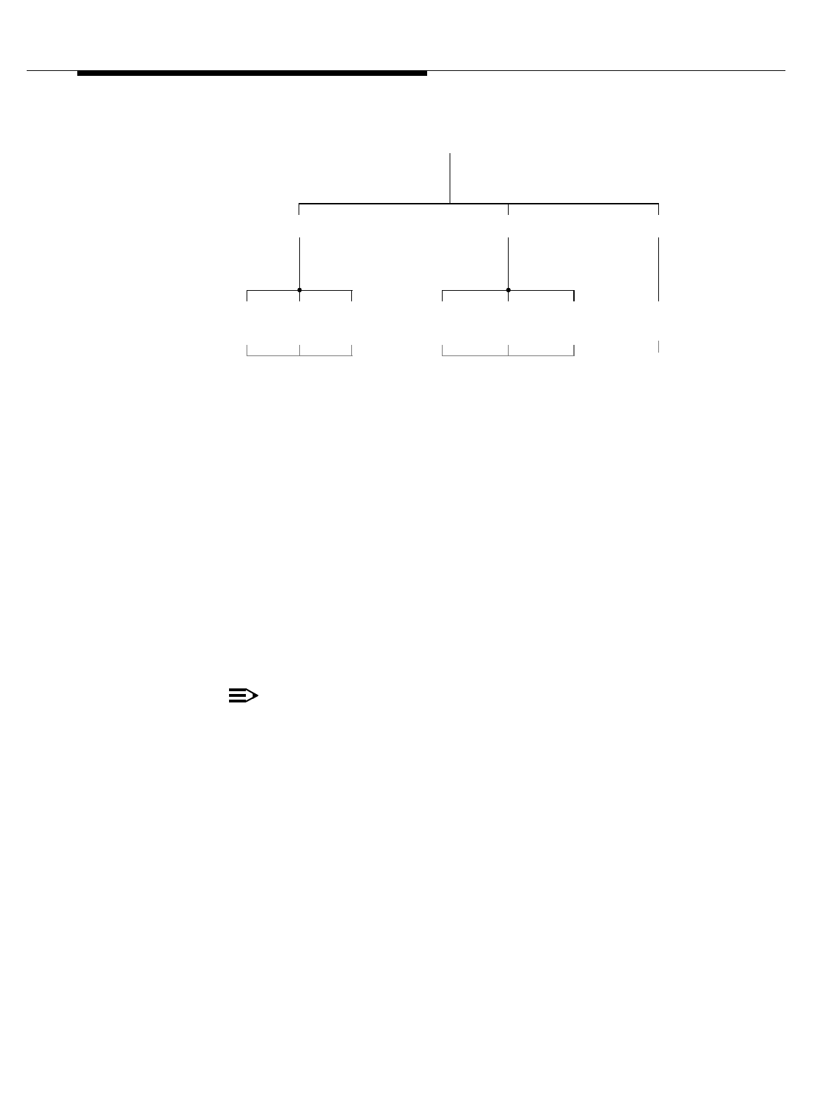
Lucent Technologies — Proprietary
See notice on first page
401-660-100 Issue 11 August 2000 14-7
Corrective Maintenance - Introduction
Figure 14-1. AMPS Radio Maintenance Units and Personality Type
TDMA Radio
Maintenance Units
and Personality
Types
For the DRU radio type, there is one NVM image file for the digital control channel
radio (D-DRU), digital voice radio (V-DRU), and digital beacon radio (B-DRU). At
initialization, the RCC downloads the personality type and other specific
parameter values to each DRU. There is another NVM image file for the digital
locate radio (L-DRU), and still another for the TRTU.
For the EDRU radio type, there is one NVM image file for the D-EDRU, V-EDRU,
and B-EDRU.
A DRU or EDRU provides a basic modulation efficiency of three user channels per
30-kHz of bandwidth. The three user channels are designated user channel 1,
user channel 2, and user channel 3. Each user channel is assigned one trunk
(DS0) on the T1 line and one duplex timeslot on the RCF internal TDM bus.
NOTE:
TDM buses are always installed "red stripe up."
The following list is a brief description of each TDMA radio personality type (Refer
to Figure 14-2):
■Digital voice radio: Performs the digital traffic channel function—carries
up to three over-the-air TDMA calls.
TECHNOLOGY
TYPE:
HARDWARE
TYPE:
PERSONALITY
TYPE:
S-SBRCU V-SBRCU L-SBRCU RTU
AMPS
S-RCU V-RCU L-RCU
SBRCU RTURCU
NVM IMAGE NVM IMAGE NVM
IMAGE

Lucent Technologies — Proprietary
See notice on first page
14-8 401-660-100 Issue 11 August 2000
Corrective Maintenance - Introduction
■Digital control channel (DCCH) radio: Performs the digital setup and
short message service functions—establishes calls via the DCCH with
mobile subscribers using IS-136 compliant TDMA/AMPS dual-mode
mobiles. The DCCH is carried on user channel 1. Typically, there is one
DCCH per physical antenna face, or sector, in a TDMA system.
■Digital beacon radio: Performs the digital beacon channel function—
transmits at a fixed level at all times to provide signal strength
measurements for the TDMA MAHO procedure. Typically, there is one
beacon radio per physical antenna face in a TDMA system.
■Digital locate radio: Performs the digital locate channel function—assists
with handoffs when the established TDMA call can be better served by an
adjacent sector or cell by measuring the signal strength and verifying the
digital verification color code (DVCC) of the IS-54B or IS-136 compliant
TDMA/AMPS dual-mode mobile targeted for handoff. The digital locate
radio is instrumental in the DVCC verification procedure.
A D-DRU or D-EDRU may also carry digital traffic and beacon channels. Thus, a
D-DRU or D-EDRU can serve three functions concurrently: (1) perform the digital
setup function—establish calls via the DCCH with mobile subscribers using
IS-136 compliant TDMA/AMPS dual-mode mobiles, (2) carry one or two over-the-
air TDMA calls, and (3) provide signal strength measurements for the TDMA
MAHO procedure. Since the RF carrier power level remains fixed for DCCH
radios, the D-DRU or D-EDRU is ineligible for dynamic power control.
The EDRU, unlike the DRU, will be able to carry more than one DCCH. That is, in
a future release, an EDRU will be able carry one, two, or three DCCHs.
A B-DRU or B-EDRU may also carry digital traffic channels. Thus, a B-DRU or
B-EDRU can serve two functions concurrently: (1) provide signal strength
measurements for the TDMA MAHO procedure and (2) carry one, two, or even
three over-the-air TDMA calls. (A digital beacon channel may double as a digital
traffic channel.) Since the RF carrier power level remains fixed for beacon radios,
the B-DRU or B-EDRU is ineligible for dynamic power control.
A V-DRU or V-EDRU may only carry digital traffic channels. A V-DRU or V-EDRU
can carry one, two, or three digital traffic channels.
An L-DRU may only carry digital locate channels. An L-DRU can carry one, two, or
three digital locate channels.
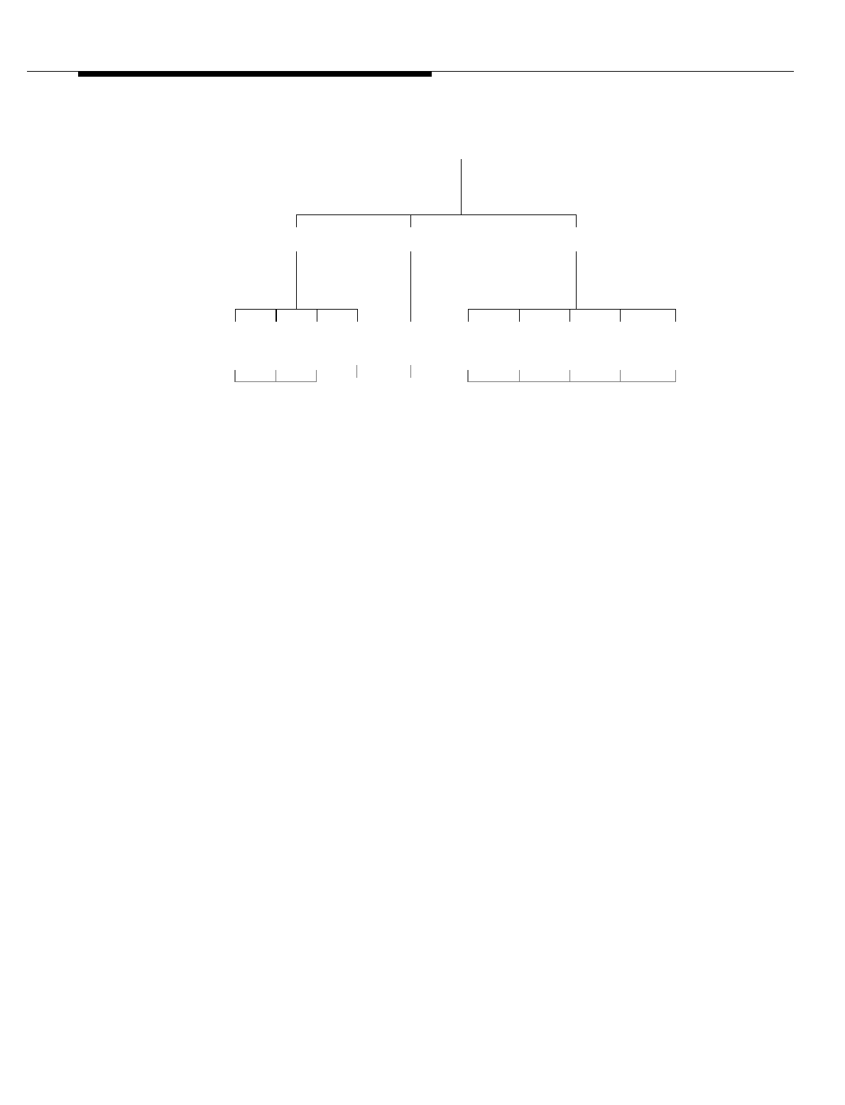
Lucent Technologies — Proprietary
See notice on first page
401-660-100 Issue 11 August 2000 14-9
Corrective Maintenance - Introduction
Figure 14-2. TDMA Radio Maintenance Units and Personality Types
CDMA Radio
Maintenance Units
and Personality
Types
For each CDMA cluster (one CCC managing up to seven CCUs), there is one
NVM image file for each of the following elements:
■the CCC
■the pilot/sync/access (P/S/A) CE personality
■the page CE personality
■the traffic CE personality
■the orthogonal-channel noise simulator (OCNS) CE personality.
At initialization, the CCC downloads the personality-type image files and other
specific parameter values into active memory of the CCUs—the CCC downloads
exactly one personality-type image file to each CCU CE. There is another NVM
image file for the BBA, another for the CRTUi, and still another for the SCT.
The CCU contains two on-board CEs. Thus, a CCC can manage up to 14 CEs.
For the cellular band class (850 MHz), the TIA IS-95A standard defines two
common carriers: the primary CDMA carrier, which is centered on RF channel
283 for System A (A band) and 384 for System B (B band), and the secondary
CDMA carrier, which is centered on RF channel 691 for System A (A’ band) and
777 for System B (B’ band). Each CDMA omni cell or cell sector must be assigned
at least one common carrier. For the PCS band class (1900 MHz), candidates for
common CDMA carriers range from channel numbers 25 to 1175 in increments
of 25.
TECHNOLOGY
TYPE:
HARDWARE
TYPE:
PERSONALITY
TYPE:
TDMA
EDRUTRTUDRU
D-DRU V-DRU L-DRU TRTUB-DRU D-EDRU V-EDRU L-EDRUB-EDRU E-TRTU
(FUTURE)
NVM IMAGE
NVM
NVM IMAGE NVM
IMAGE IMAGE
(FUTURE)

Lucent Technologies — Proprietary
See notice on first page
14-10 401-660-100 Issue 11 August 2000
Corrective Maintenance - Introduction
Each common CDMA carrier (primary, secondary) on an antenna face has one
CE configured as the P/S/A CE and another configured as the page CE. The two
CEs may be on the same CCU or on different CCUs within the same CDMA
cluster.
The following list provides a brief description of each CDMA CE personality type
(Refer to Figure 14-3):
■Pilot/Sync/Access CE: Performs part of the CDMA call setup function—
establishes calls with mobile subscribers using IS-95A or IS-95B compliant
CDMA/AMPS dual-mode mobiles.
The pilot channel is an unmodulated, direct-sequence spread-spectrum
signal transmitted continuously by each sector of a CDMA cell. It allows the
mobile to acquire the timing of the forward control channels and provides a
coherent carrier phase reference for demodulating the sync and paging
channels.
The sync channel provides time-of-day and frame synchronization to the
mobile. The mobile uses this channel to acquire cell and sector-specific
information.
The access channel is a CDMA reverse channel used for short signaling
message exchange such as mobile registration, mobile call origination, and
response to pages. The access channel is a slotted random access
channel used by mobiles to communicate to the Cell Site.
■Page CE: Performs part of the CDMA call setup function—transmits control
information to idle mobiles during mobile powerup and when a mobile is
acquiring a new Cell Site. It conveys pages to the mobiles.
■Traffic CE: Performs the CDMA traffic channel function—carries one over-
the-air CDMA call. A traffic channel, which is a communication path
between a mobile station and a Cell Site, carries user and signaling
information. The term traffic channel implies a forward and reverse pair.
■OCNS CE: Simulates a specified number of mobile users operating in a
specified sector on a specified carrier. OCNS allows generation of a
simulated user load on the CDMA forward channels in order to assist in
verifying the capacity of the CDMA system.
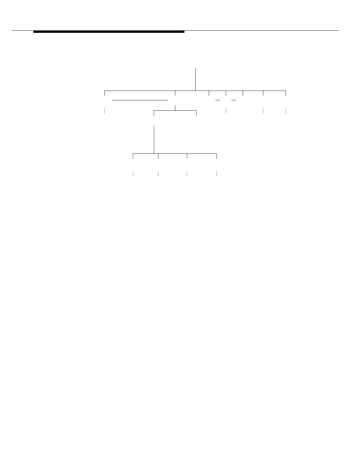
Lucent Technologies — Proprietary
See notice on first page
401-660-100 Issue 11 August 2000 14-11
Corrective Maintenance - Introduction
Figure 14-3. CDMA Radio Maintenance Units and Personality Types
TECHNOLOGY
TYPE:
HARDWARE
TYPE:
PERSONALITY
TYPE:
CDMA
ACU*CCUCCC
P/S/A CE PAGE CE OCNS CETRAFFIC CE
SCTBCR* BIU* CRTUi
NVM
IMAGE NVM
IMAGE NVM
IMAGE NVM
IMAGE
CE CE
NVM
IMAGE NVM
IMAGE NVM
IMAGE
NVM
IMAGE
* BCR-BIU-ACU = BBA

Lucent Technologies — Proprietary
See notice on first page
14-12 401-660-100 Issue 11 August 2000
Corrective Maintenance - Introduction
Maintenance States
During installation, each unit is assigned an equipment state of unequipped,
growth, or equipped via translations (system configuration parameter settings).
Each equipped unit is further assigned a state of active, out-of-service, or standby
(redundant unit only) via maintenance requests sent to the MRA subsystem.
Maintenance states The meanings of the maintenance states are as follows:
Active
Unit is available for its intended use; for example, an RCU can service a call, the
RTU can be used to test analog radio equipment, etc.
Standby
Unit is available to be placed into the active state; applies only to redundant units
RCC, CAT, SCT, BBA, and setup radio (S-RCU, S-SBRCU).
(Because the BBA is a single point failure for a sector, redundant BBAs—one
active and the other in standby mode—may be installed for increased reliability.
Currently, redundant BBAs may only be installed in the non-subcell configuration.)
(Setup radios are considered redundant when there are spare setup radios at the
Cell Site. For Cell Sites having the automatic radio reconfiguration—ARR—feature
active for setup radios, there are no spare setup radios at the Cell Site: in that
case, setup radios are not redundant.)
Unequipped
Unit exists in the translations data base strictly as a place holder. MRA will reject
any maintenance request targeted for an unequipped unit.
Out-Of-Service
Unit is not available for its intended use (exact opposite of active state), but is
available to be diagnosed or updated with NVM.
Growth State
Unit is not available to be placed in use, but is available to be diagnosed or
updated with NVM.
Throughout the maintenance process, MRA records locally the maintenance
status of the Cell Site equipment in the equipment status table. The maintenance
status of equipment is reported to the ECP when the status changes or the ECP

Lucent Technologies — Proprietary
See notice on first page
401-660-100 Issue 11 August 2000 14-13
Corrective Maintenance - Introduction
requests an update. The status of Cell Site equipment appears in the status
display pages.

Lucent Technologies — Proprietary
See notice on first page
14-14 401-660-100 Issue 11 August 2000

Lucent Technologies — Proprietary
See notice on first page
401-660-100 Issue 11 August 2000 15-1
15
Corrective Maintenance using MRA
Contents
■Contents 15-1
■Maintenance Request Administrator (MRA) 15-2
■Diagnose 15-3
Related Documents 15-4
Stop a Diagnostic 15-4
Obtain Status 15-4
Related Documents 15-4
Qualifiers Associated with the Out-Of-Service (OOS) State 15-4
■Dual Server Group Out-Of-Service (OOS) Limits 15-6
New RC/V Translation Parameters 15-6
■Remove/Restore/Switch Actions 15-7
Conditional Remove 15-7
Unconditional Remove 15-11
Conditional and Unconditional Restore 15-13
Related Documents 15-16
Switch to a Redundant Unit 15-16
Related Documents 15-17

Lucent Technologies — Proprietary
See notice on first page
15-2 401-660-100 Issue 11 August 2000
Corrective Maintenance using MRA
Maintenance Request Administrator
(MRA)
Maintenance activities for the cell site’s primary and growth radio channel frames
(RCFs) are done through a series of software subsystems that reside in the radio
control complex (RCC). One such software subsystem is the maintenance request
administrator (MRA), which provides maintenance personnel with control, routing,
and diagnostic maintenance procedures.
MRA receives maintenance requests from the ECP, performs the maintenance
activities associated with the requests, and returns the results and collected data
(if any) to the ECP. MRA handles requests to return information about the cell site,
to remove (deactivate) cell site equipment, to restore (activate) cell site
equipment, to perform diagnostic tests on cell site equipment, and so on.
The MRA subsystem not only responds to external requests from the ECP, but
also responds to internal requests submitted by other software subsystems, such
those performing automatic fault recovery or scheduled maintenance.
The rest of this section describes the Cell Site units that require maintenance, the
types of maintenance states that exist, and the maintenance actions that can be
taken.

Lucent Technologies — Proprietary
See notice on first page
401-660-100 Issue 11 August 2000 15-3
Corrective Maintenance using MRA
Diagnose
The diagnose maintenance action can be applied to a unit in the out-of-service or
growth state, to a redundant unit in the standby state, or to a redundant unit in the
active state. In the latter case, MRA initiates a switch before executing the
diagnose request.
NOTE:
For redundant units, if the targeted unit is in the active state but the mate is
out-of-service, the diagnose aborts with no action taken. In addition, if the
targeted unit is an active SCT, the diagnose aborts with no action taken
even if the SCT has a standby mate.
In addition, the diagnose maintenance action can be applied to a CCC, CCU, or
CRTU in the active state. The first step in a diagnose maintenance action for an
active CCC, CCU, or CRTU is the automatic execution of a conditional remove.
Whether a unit passes or fails diagnostics, the unit is left in the out-of-service state
except for a unit in the growth state. A unit initially in the growth state remains in
the growth state. The diagnostic test results (pass, fail) are reported to the ECP.
A diagnostic test can be called for the whole RCC (in which all controller circuit
boards are tested), or a diagnostic test can be called for an individual controller
circuit board (for example, CPU).
For diagnose requests pertaining to radios involved in ARR, you need to be aware
of the following conditions:
■A diagnose request without the qualifier orig is applied to the replacement
radio; the rules governing the behavior of the diagnose command remain in
effect dur-ing an ARR condition. A diagnose request of a setup, DCCH,
beacon, or analog locate radio involved in an ARR condition is rejected
because diagnosing an active unit is not permitted.
To diagnose a replacement radio, first unconditionally remove the radio, then
diagnose the radio. Whether the replacement radio passes or fails diagnostics, the
radio is left in the out-of-service state and the ARR condition remains in effect.
■A diagnose request with the qualifier orig is applied to the original radio;
whether the original radio passes or fails diagnostics, the radio is left in the
out-of-service state and the ARR condition remains in effect.
■A diagnose request applied directly to the replacement radio (say RA10) is
rejected because that functionality is unavailable due to the ARR. An
output report message appears stating that the radio is being borrowed by
the ARR fea-ture and is not available.

Lucent Technologies — Proprietary
See notice on first page
15-4 401-660-100 Issue 11 August 2000
Corrective Maintenance using MRA
Related
Documents For more information on the diagnose maintenance action, refer to the DGN
CELL, DGN CELL DL, and DGN CELL SG commands in the Input Messages
manual (401-610- 055).
Stop a Diagnostic The stop maintenance action stops a diagnostic test on a maintenance unit. If the
diagnostic test request is still in the job queue, MRA removes the request from the
queue. If the diagnostic test is running, MRA aborts the test.
MRA leaves the unit in the out-of-service or growth state unless the unit is a CCC,
CCU, BBA, or CRTU. Upon terminating a diagnostic test for one of those units,
MRA returns the unit to the state it was in just prior to the diagnostic request
(out-of-service, growth, or active) unless the diagnostic test is already running on
the unit, in which case the unit is left in the out-of-service state.
For more information on the stop a diagnostic maintenance action, refer to the
STOP DGN CELL, STOP DGN CELL DL, and STOP DGN CELL SG commands
in the Input Messages manual (401-610-055).
Obtain Status The obtain status maintenance action determines the status (state) of a
maintenance unit, that is, MRA reads the recorded status from the equipment
status table and forwards the status to the ECP. In addition, MRA automatically
reports the maintenance status of equipment to the ECP whenever the status
changes. A status display page is refreshed with new maintenance status every
15 seconds.
Related
Documents For more information on the obtain status maintenance action, refer to the OP
CELL, OP CELL DL, OP CELL DLOPTS, OP CELL EXTERN, OP CELL
GENERIC, OP CELL OVLD, OP CELL SCSM, OP CELL SG, and OP CELL
VERSION commands in the Input Messages manual (401-610-055).
Qualifiers
Associated with
the Out-Of-Service
(OOS) State
A maintenance unit can be placed in the out-of-service state due to one of several
reasons. To identify the reason that a unit is in the out-of-service state, MRA
assigns the unit a qualifier in addition to its final state of OOS. MRA assigns a
qualifier to a unit during execution of the maintenance request (See Table 15-1).
Both the qualifier and final state of the unit are reported to the ECP.
Table 15-1. OOS State Quilifiers
Qualifier Description
OOS-DGN The unit is in the out-of-service state due to the successful completion
of a diagnose request.
OOS-FAULT The unit is in the out-of-service state due to fault detection during
diag-nostics in the Cell Site.
OOS-INITF The unit is in the out-of-service state due to an unsuccessful initial-
iza-tion process.
OOS-NVMUPT The unit is in the out-of-service state because its NVM is being updated.

Lucent Technologies — Proprietary
See notice on first page
401-660-100 Issue 11 August 2000 15-5
Corrective Maintenance using MRA
OOS-RMVD The unit is in the out-of-service state due to the successful completion
of a remove request.
OOS-TBLANL This qualifier is used for leaving a unit in OOS state after it has suc-
cess-fully passed diagnostics but is still reporting faults. This state is
known as the trouble-analysis state.
OOS-CDMAF The CCC, CCU, or BBA is in the out-of-service state due to no CDMA
timing.
OOS-CFR The BBA is in the out-of-service state due to its involvement in a
multi-ple configure (MULTI CFR) test.
OOS-DNP The previously active CCU is in the out-of-service state due to the
removal of two consecutive downstream
CCUs. OOS-POS The previously active CCU is in the out-of-service state due to the
suc-cessful completion of a remove request of the parent
CCC. OOS-RMVIP The DS1 is currently being removed.
Table 15-1. OOS State Quilifiers (Contd)
Qualifier Description

Lucent Technologies — Proprietary
See notice on first page
15-6 401-660-100 Issue 11 August 2000
Corrective Maintenance using MRA
Dual Server Group Out-Of-Service
(OOS) Limits
For a Series II Dual Server Group cell, configured as either a 3-sector or 6-sector
cell, Voice Radio Out-Of-Service (OOS) limits can now be set on a per Logical
Antenna Face (LAF) level, rather than on a per-cell level.
Previously, OSS limits functioned as follows: The OOS limits could only be
defined, or set, on a per-cell basis. However, the software that performed OOS
checking for conditional OA&M commands, checked on a per LAF basis.
Therefore, it was possible for per- cell OSS limits to block the testing of radios on a
particular LAF.
This is no longer a problem. The ability to set OOS limits on a per LAF basis
allows the service-provider to set the voice radio OSS limits at the same level at
which the Cell Site software performs the OOS checking for conditional OA&M
commands; that is, at the per LAF level.
New RC/V
Translation
Parameters
This feature adds 4 new AMPS and TDMA Voice Radio OOS limit translations to
the ceqface form, as below:
1. AMPS Voice Radio OOS Limit Server Group 0. This parameter defines the
AMPS Voice Radio Out of Service Limit for Server Group 0.
2. AMPS Voice Radio OOS Limit Server Group 1. This parameter defines the
AMPS Voice Radio Out of Service Limit for Server Group 1.
3. TDMA Voice Radio OOS Limit Server Group 0. This parameter defines the
TDMA Voice Radio Out of Service Limit for Server Group 0.
4. TDMA Voice Radio OOS Limit Server Group 1 This parameter defines the
TDMA Voice Radio Out of Service Limit for Server Group.
For all 4 translations, the following apply:
■The view is Per Logical Face.
■The Allowable Values are 1 to 100% or Blank.
■The Default is Blank.
■The Restriction is that, if no value is entered (i.e., Blank), the value defaults
to the Per Cell Voice.
■Radio Out of Service Limit.
■Update is allowable.

Lucent Technologies — Proprietary
See notice on first page
401-660-100 Issue 11 August 2000 15-7
Corrective Maintenance using MRA
Remove/Restore/Switch Actions
Maintenance actions can be applied to maintenance units through commands
from the ECP or by Cell Site software processes.
The yes and no entries under the maintenance actions in shown in the figures at
the beack of this chapter indicate whether a maintenance action is permitted for a
maintenance unit. In the rows of the table that have NULL in the Subunit column,
the action is applied to the maintenance unit specified in the Unit column; in the
rows of the table that do not have NULL in the Subunit column, the action is
applied to the maintenance unit specified in the Subunit column.
The c and u entries under the maintenance actions in the table indicate whether a
remove or restore maintenance action is conditional or unconditional. In general, a
conditional maintenance request will not result in any action that causes calls to
be dropped or service denied to a user during the course of command execution;
if executing a conditional request would violate either condition, MRA would reject
the request. In contrast, an unconditional maintenance request will result in the
execution of the request immediately or within five minutes of MRA accepting the
request, with little concern to whether calls are dropped or service denied to a
user during the course of command execution.
If a unit is involved in an automatic radio configuration (ARR) when a maintenance
action is applied, the maintenance action is applied to the replacement radio
unless orig is specified in the maintenance request, in which case the
maintenance action is applied to the original radio. Any maintenance action
applied directly to the replacement radio (say RA10) will be rejected because that
functionality is unavailable due to the ARR.
The ARR feature applies to AMPS and TDMA but not to CDMA.
All maintenance actions (remove, restore, diagnose, stop a diagnostic, switch to
redundant unit, and obtain status) are reported to the ECP.
Once a maintenance action has started on a maintenance unit, MRA will reject
any subsequent maintenance-action request for that unit until the current action
has completed with the following exception: for any given unit, an unconditional
maintenance-action request can terminate a conditional maintenance-action
request.
Conditional
Remove The conditional remove maintenance action changes the state of a maintenance
unit from active or standby to out-of-service. It schedules an event or process to
place the specified maintenance unit to out-of-service assuming that it is
idle_NOT busy. An idle unit is in the active state but not currently performing its
intended purpose; a busy unit is in the active state and currently performing its
intended purpose, such as a V-RCU supporting an active call.

Lucent Technologies — Proprietary
See notice on first page
15-8 401-660-100 Issue 11 August 2000
Corrective Maintenance using MRA
If the unit is a busy V-RCU, V-SBRCU, V-DRU, V-EDRU, CCC, or CCU when the
conditional remove action is applied, the unit is blocked (not allowed to accept new
calls), and the remove is deferred for up to five minutes. As soon as the unit
becomes idle (free of all calls) during the five-minute interval, it is removed from
service. If the unit is still busy after five minutes, the conditional remove aborts
with no action taken.
If the unit is a CCC carrying overhead channels, MRA will attempt to migrate the
overhead channels to CEs on the other-side CDMA cluster on the same
shelf_select two idle traffic CEs on the other-side CDMA cluster on the same shelf
and reconfigure them as the overhead channels. The overhead channel CEs for a
common CDMA carrier on an omni cell or cell sector must be on the same CDMA
cluster, that is, must be controlled by the same CCC.
If the unit is a CCU carrying an overhead channel, MRA will attempt to migrate the
overhead channel to another CE on the same CDMA cluster_select an idle traffic
CE on the same CDMA cluster and reconfigure it as the overhead channel. If that
attempt fails, MRA will attempt to migrate the overhead channel to an idle traffic
CE on the other-side CDMA cluster on the same shelf.
If the migration is successful, MRA will initiate a CDMA overhead channel
functional test to verify the operation of the newly assigned overhead channels (or
channel).
For redundant units, if the unit is in the standby state when the conditional remove
action is applied, the unit is removed from service immediately. If the unit is in the
active state and the mate in the standby state when the conditional remove action
is applied, MRA automatically executes a switch before removing the unit from
service. And finally, if the unit is in the active state and the mate in the
out-of-service state when the conditional remove action is applied, the conditional
remove aborts with no action taken. ( Exception: if the BBA out-of-service
threshold limit is set to 100%, the remove request will continue.)
Currently, redundant BBA operation is supported in the non-subcell configuration
but not the subcell configuration. Only simplex BBA operation_one BBA per
CDMA shelf_ is supported in the subcell configuration. Other conditions that will
cause the conditional remove to abort with no action taken are described as
follows:
■A conditional remove action on a unit in the growth state is not permitted
unless the unit is a CCC, CCU, or BBA. A conditional remove action of a
CCC, CCU, or BBA in the growth state simply resets the unit; the unit
remains in the growth state.
■If placing the unit out-of-service would result in exceeding the
out-of-service threshold limit for that type of unit, the conditional remove
action is not permitted.

Lucent Technologies — Proprietary
See notice on first page
401-660-100 Issue 11 August 2000 15-9
Corrective Maintenance using MRA
A 100% out-of-service threshold limit for a particular type of unit means that any
number (one to all) of those units may be conditionally removed. A 0%
out-of-service threshold limit for a particular type of unit means that not even one
of those units may be conditionally removed.
Out-of-service threshold limits for analog voice radios, analog locate radios, digital
voice radios, and digital locate radios are translatable, that is, specified using the
recent change/verify (RC/V) subsystem at the ECP (specifically, using RC/V form
cell2). Out-of-service threshold limits for setup radios, DCCH radios, and beacon
radios are not translatable. Effectively, the out-of-service limit for each of these
radio types is 0%, meaning that removing just one such radio would exceed the
radio out-of-service threshold limit.
Out-of-service threshold limits for CDMA traffic CEs and BBAs are translatable on
a per antenna face (sector and carrier) basis using the RC/V form cell2. The range
is 25% to 100%; the default is 25%. Blocked traffic CEs are included in the
out-of-service threshold limit calculations. Overhead CEs (pilot/sync/ access and
page) are not included in the out-of-service threshold limit calculations.
(In a CDMA subcell configuration, MRA adds the individual antenna face
out-of-service threshold limits together to obtain a total out-of-service threshold
limit for the whole subcell. For example, if the face out-of-service threshold limit is
25% and each shelf is equipped with 26 traffic channels, the individual face
out-of-service threshold limit is six traffic channels. If all three faces are served by
all three shelves_a 3-shelf subcell configuration, the total out-of-service threshold
limit for the whole subcell is 18 traffic channels, meaning that MRA would check
for an out-of-service threshold limit of 18 traffic channels for the whole subcell. In
this example, MRA would only allow a single CDMA cluster to be conditionally
removed.)
(The removal of any two adjacent CCUs will break the transmit bus path, thereby
disrupting the transmit data upstream from the break. As an example, removing
CCUs 2 and 3 will also remove CCUs 4 through 7. For a conditional remove
request, MRA will not permit the removal of two adjacent CCUs if the removal
would result in exceeding the traffic CE out-of-service threshold limit.)
■A conditional remove action on a DS1 or DFI is not permitted if the
out-of-service limit would be exceeded for voice radios.
■A conditional remove action on a DS1 or DFI is not permitted if that unit
controls the last data link to a Cell Site.
■A conditional remove action on the last data link to a Cell Site is not
permitted. (Only an unconditional remove action on the last data link can
remove the data link from service.)

Lucent Technologies — Proprietary
See notice on first page
15-10 401-660-100 Issue 11 August 2000
Corrective Maintenance using MRA
■A conditional remove action on an RTU, TRTU, or CRTU involved in
diagnostics of another unit_such as during a setup radio, DCCH radio, or
CDMA radio functional test_is not permitted. (This restriction avoids false
errors that may be generated upon premature termination of the diagnostic
test involving the RTU, TRTU, or CRTU.)
■A conditional remove action on a CAT or SCT involved in diagnostics of
another unit_that is, CAT or SCT supplying a digital tone source_is not
permitted. (This restriction avoids false errors that may be generated upon
premature termination of the diagnostic test involving the CAT or SCT.)
■Neither a conditional nor unconditional remove action is permitted on the
last CAT or SCT on a TDM bus (TDM0 or TDM1). Note: TDM buses are
always installed "red stripe up."
■Neither a conditional nor unconditional remove action is permitted on SCT
4 if SCT 5 is already out-of-service, on SCT 5 if SCT 4 is already
out-of-service.
■A conditional remove action on an active SCT_even though its mate may
be in standby_is not permitted.
(In general, any conditional maintenance request that would normally cause
redundant units to switch is not permitted for SCTs. The switching of SCTs could
leave the associated CDMA hardware_the CCCs and CCUs that are receiving
CDMA timing from the redundant SCTs_in an unknown state, which would require
the manual restore of the affected CCCs.)
■A conditional remove action on a setup radio having no associated spare is
not permitted. (Only an unconditional remove action on a setup radio
having no associated spare_other than a hard fault_can remove the radio
from service.)
■A conditional remove action on a DCCH radio is not permitted. (Only an
uncondi-tional remove action on a DCCH radio_other than a hard fault_can
remove the radio from service.)
■A conditional remove action on a beacon radio is not permitted. (Only an
uncon-ditional remove action on a beacon radio_other than a hard
fault_can remove the radio from service.)
(By definition, a beacon radio may be a B-DRU or a B-EDRU, or a V-RCU
or V-SBRCU configured as a beacon radio. Be aware, though, that
because setup and DCCH radios have their transmitters On all the time
and transmit at fixed power levels, they too may serve as beacon-like
radios.)
■For radios involved in ARR:

Lucent Technologies — Proprietary
See notice on first page
401-660-100 Issue 11 August 2000 15-11
Corrective Maintenance using MRA
—A conditional remove request without the qualifier orig is applied to
the replacement radio; the rules governing the behavior of the
conditional remove command for each type of radio (setup, DCCH,
beacon, analog locate) remain in effect during an ARR condition.
A conditional remove request of a setup, DCCH, or beacon radio
involved in an ARR condition is not permitted. A conditional remove
request of an analog locate radio involved in an ARR condition is
permitted as long as such an action would not violate out-of-service
limits for analog locate radios.
—A conditional remove request with the qualifier orig is applied to the
origi-nal radio; the request is rejected because the orig qualifier is
not sup-ported for the RMV CELL (remove cell) command.
—A conditional remove request applied directly to the replacement
radio (say RA10) is rejected because that functionality is unavailable
due to the ARR. An output report message appears stating that the
radio is being borrowed by the ARR feature and is not available.
For more information on the remove maintenance action, refer to the RMV CELL
and RMV CELL SG commands in the Input Messages manual (401-610-055).
Unconditional
Remove Unconditional remove requests may be service affecting because of the
out-of-service limits that may be exceeded. For example, service to a Cell Site is
affected if the last setup radio is removed.
The unconditional remove maintenance action changes the state of a
maintenance unit from active or standby to out-of-service. It promptly places the
specified maintenance unit in the out-of-service state unless any of the following
conditions are in effect:
■The unconditional remove action is targeted for a busy V-RCU, V-SBRCU,
V-DRU, V-EDRU, CCC, CCU, or a BBA having no mate or the mate is
out-of-ser-vice. The remove is deferred for up to five minutes. As soon as
the unit becomes idle during the five-minute interval, MRA removes the unit
from service. If the unit is still busy after five minutes, MRA drops the calls
and removes the unit from service.
Be aware that the removal of any two adjacent CCUs will break the transmit bus
path, thereby disrupting the transmit data upstream from the break. As an
example, removing CCUs 2 and 3 will also remove CCUs 4 through 7. For an
unconditional remove request, MRA will allow the removal of two adjacent CCUs
with no regard for the traffic CE out-of-service threshold limit.
■The unconditional remove action is targeted for a DS1 or DFI that, if
removed, would result in the exceeding of the out-of-service limit for voice
radios. The unconditional remove aborts with no action taken.

Lucent Technologies — Proprietary
See notice on first page
15-12 401-660-100 Issue 11 August 2000
Corrective Maintenance using MRA
■The unconditional remove action is targeted for a unit in the growth state.
The unconditional remove aborts with no action taken unless the unit is a
CCC, CCU, or BBA. An unconditional remove action of a CCC, CCU, or
BBA in the growth state simply resets the unit; the unit remains in the
growth state.
■The unconditional remove action is targeted for a redundant RCC, CAT, or
SCT having an out-of-service mate. The unconditional remove aborts with
no action taken.
An unconditional remove action targeted for a redundant setup radio having an
out-of-service mate will be honored immediately by MRA. After the removal, both
the setup radio and its mate will be out-of-service.
Be aware that an unconditional remove request of an active SCT having a standby
mate will result in a SCT switch, which could leave the associated CDMA
hardware_ the CCCs and CCUs that are receiving CDMA timing from the
redundant SCTs_in an unknown state. You would have to manually restore the
affected CCCs.
If an RTU, TRTU, or CRTU is involved in diagnostics of another unit, an
unconditional remove request of the unit terminates the ongoing diagnostics,
which may result in the generation of false errors upon premature termination of
the diagnostic test.
Similarly, if a CAT or SCT is involved in diagnostics of another unit, an
unconditional remove request of the unit terminates the ongoing diagnostics,
which may result in the generation of false errors upon premature termination of
the diagnostic test.
Other conditions pertaining to unconditional remove requests that you need to be
aware of are as follows:
■If the requested unit is a setup radio having no associated spare, the radio
will be removed without invoking ARR. A warning message appears stating
that the radio removed was a setup radio.
■If the requested unit is a DCCH radio, the radio will be removed without
invoking ARR, even if it is the last DCCH for the sector. A warning message
appears stat-ing that the radio removed was a DCCH radio.
■If the requested unit is a beacon radio, the radio will be removed without
invoking ARR. A warning message appears stating that the radio removed
was a beacon radio.
■For radios involved in ARR:

Lucent Technologies — Proprietary
See notice on first page
401-660-100 Issue 11 August 2000 15-13
Corrective Maintenance using MRA
—An unconditional remove request without the qualifier orig is applied
to the replacement radio; when the radio is removed, MRA
remembers the ARR condition; when the radio is restored, MRA
continues the ARR_the ARR condition remains in effect.
—An unconditional remove request with the qualifier orig is applied to
the original radio; the request is rejected because the orig qualifier is
not sup-ported for the RMV CELL (remove cell) command.
—An unconditional remove request applied directly to the replacement
radio (say RA10) is rejected because that functionality is unavailable
due to the ARR. An output report message appears stating that the
radio is being borrowed by the ARR feature and is not available.
Conditional and
Unconditional
Restore
The restore maintenance action can be applied to units that are in the
out-of-service, active, or standby state. Except for a unit that is already
out-of-service or in the growth state, the first step in a conditional restore
maintenance action is the automatic execution of a conditional remove. Therefore,
all the restrictions associated with a conditional remove are also associated with a
conditional restore.
Similarly, except for a unit that is already out-of-service or in the growth state, the
first step in an unconditional restore maintenance action is the automatic
execution of an unconditional remove. Therefore, the lack of restrictions
associated with an unconditional remove_unconditional remove requests may be
service affecting_are also associated with an unconditional restore.
The conditional restore maintenance action changes the state of a maintenance
unit to active. It schedules an event or process to restore the specified
maintenance unit after the unit passes a diagnostic test. If the unit fails the
diagnostic test, the conditional restore aborts. The failed unit remains in the
out-of-service state.
The unconditional restore maintenance action changes the state of a
maintenance unit to active. It schedules an event or process to restore the
specified maintenance unit without first running a diagnostic test on the unit.
NOTE:
For a redundant unit (RCC, CAT, SCT, BBA, or setup radio), you can specify
the STBY parameter in the RST command line to restore the unit to the
standby state.
A conditional restore request on a unit in the growth state will diagnose and
initialize the unit but will not change the state of the unit: the unit remains in the
growth state. An unconditional restore of a unit in the growth state is not permitted
unless the unit is a CCC, CCU, or BBA. An unconditional restore action of a CCC,
CCU, or BBA in the growth state (1) initializes the CCC as an active CCC with call
processing and error reporting inhibited, (2) configures all CEs on the CCU as

Lucent Technologies — Proprietary
See notice on first page
15-14 401-660-100 Issue 11 August 2000
Corrective Maintenance using MRA
traffic channels, or (3) initializes the BBA as a standby BBA; the unit remains in
the growth state.
Other conditions pertaining to conditional and unconditional restore requests that
you need to be aware of are as follows:
■For data links (DLs):
—A conditional restore request reverts to unconditional if there is no
link currently in-service; no diagnostic test is run.
—No action is performed if an unconditional restore request is made
on the currently in-service link.
■For redundant units:
—An RCC conditional restore request compares the active and mate
mem-ories of the controller sides (RCC 0 and RCC 1) after the RCC
being restored has elevated to the standby state. A mismatch in
memory drops the RCC back to the out-of-service state and aborts
the restore request.
—An active RCC, CAT, or SCT having an out-of-service mate cannot
be conditionally or unconditionally restored.
—An active BBA having an out-of-service mate cannot be
conditionally restored unless (1) the BBA out-of-service threshold
limit is set to 100% and (2) the BBA becomes idle_free of
calls_within five minutes of issu-ing the conditional restore
command. An active BBA having an out-of-ser-vice mate can be
unconditionally restored.
—An active setup radio having an out-of-service mate cannot be
condition-ally restored but can be unconditionally restored.
—An active SCT having a standby mate cannot be conditionally
restored but can be unconditionally restored.
(In general, any conditional maintenance request that would
normally cause redundant units to switch is not permitted for SCTs.
The switching of SCTs could leave the associated CDMA
hardware_the CCCs and CCUs that are receiving CDMA timing
from the redundant SCTs_in an unknown state, which would require
the manual restore of the affected CCCs.)
—A standby SCT can be conditionally restored to the standby state
but not the active state. In contrast, a standby SCT can be
unconditionally restored to either the standby or active state.
■For setup radios:
—A conditional restore action on an active setup radio having no
associated spare is not permitted.

Lucent Technologies — Proprietary
See notice on first page
401-660-100 Issue 11 August 2000 15-15
Corrective Maintenance using MRA
—An unconditional restore action on an active setup radio having no
associated spare is permitted.
—If call processing is inhibited, setup radios are in the standby state.
■For both setup and analog locate radios:
—If a radio that was conditionally restored becomes active, a
functional test is immediately scheduled for the radio.
■For DCCH radios:
—A conditional restore action on an active DCCH radio is not
permitted.
—An unconditional restore action on an active DCCH radio is
permitted, even if it is the last DCCH for the sector. The
unconditional restore action resets the DCCH (that is, resets the
DRU or EDRU carrying the DCCH).
■For beacon radios:
—A conditional restore action on an active beacon radio is not
permitted.
—An unconditional restore action on an active beacon is permitted.
—A beacon radio’s transmitter is always turned back On as part of a
radio restore request sequence.
For radios involved in ARR:
■A conditional restore request without the qualifier orig is applied to the
replace-ment radio; the rules governing the behavior of the conditional
restore command for each type of radio (setup, DCCH, beacon, analog
locate) remain in effect dur-ing an ARR condition.
A conditional restore request of an active setup, DCCH, or beacon radio
involved in an ARR condition is not permitted. A conditional restore request
of an active analog locate radio involved in an ARR condition is permitted
as long as such an action would not violate out-of-service limits for analog
locate radios
To conditionally restore a replacement radio, first unconditionally remove
the radio, then conditionally restore the radio. If the replacement radio
passes diag-nostics, the radio is restored to the active state. If the
replacement radio fails diagnostics, the radio is left in the out-of-service
state. Whether the replacement radio passes or fails diagnostics, the ARR
condition remains in effect.
■A conditional restore request with the qualifier orig is applied to the original
radio. If the original radio passes diagnostics, the radio is restored to
service with its original personality and the replacement radio resumes its

Lucent Technologies — Proprietary
See notice on first page
15-16 401-660-100 Issue 11 August 2000
Corrective Maintenance using MRA
former personality_ the ARR condition is terminated (reversed). If the
original radio fails diagnostics, the radio is left in the out-of-service state
and the ARR condition remains in effect.
■A conditional restore request applied directly to the replacement radio (say
RA10) is rejected because that functionality is unavailable due to the ARR.
An output report message appears stating that the radio is being borrowed
by the ARR feature and is not available.
■An unconditional restore request without the qualifier orig is applied to the
replacement radio. If the restore action is successful, the replacement radio
is restored to the active state. If the restore action fails, the replacement
radio is left in the out-of-service state. Whether the restore action is
successful or unsuc-cessful, the ARR condition remains in effect.
■An unconditional restore request with the qualifier orig is applied to the
original radio. If the restore action is successful, the original radio is
restored to the active state and the ARR condition is terminated (reversed).
If the restore action fails, the original radio is left in the out-of-service state
and the ARR condition remains in effect.
■An unconditional restore request applied directly to the replacement radio
(say RA10) will be rejected because that functionality is unavailable due to
the ARR. An output report message appears stating that the radio is being
borrowed by the ARR feature and is not available.
Related
Documents For more information on the restore maintenance action, refer to the RST CELL
and RST CELL SG commands in the Input Messages manual (401-610-055).
Switch to a
Redundant Unit The switch to redundant unit maintenance action changes the state of a
maintenance unit from active to standby while at the same time changing the state
of a second unit (the associated redundant unit) from standby to active. The
purpose of the maintenance action is to transfer the functions of the first unit to the
second unit. (This maintenance action applies only to the RCC, CAT, SCT, BBA, or
setup radio).
If either of the redundant units is in the out-of-service state, the switch request
aborts with no action taken. For the CAT or SCT, the switch request will fail if the
CAT/ SCT is involved in diagnostics of another unit. (Does not apply to SCT units
having logical CAT numbers 4 and 5.)
!CAUTION:
Be aware that a switch action on a SCT could leave the associated CDMA
hard-ware_the CCCs and CCUs that are receiving CDMA timing from the
redundant SCTs_in an unknown state. You would have to manually restore
the affected CCCs.
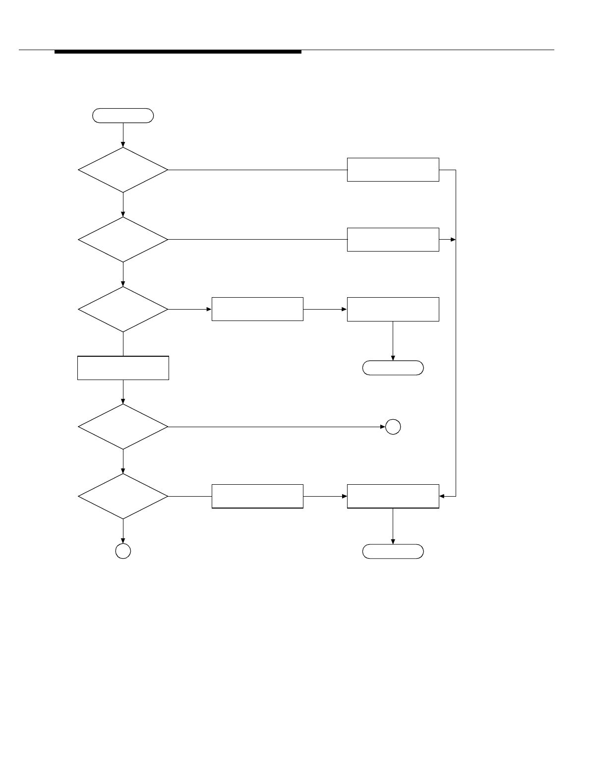
Lucent Technologies — Proprietary
See notice on first page
401-660-100 Issue 11 August 2000 15-17
Corrective Maintenance using MRA
Related
Documents For more information on the switch to redundant unit maintenance action, refer to
the SW CELL command in the Input Messages manual (401-610-055).
Figure 15-1. Remove Flow of Voice Radio RCU, SBRCU, DRU, or EDRU
(Sheet 1 of 3)
Remove radio again
and tag unit OOS-
Is remove
request conditional or
unconditional
?
Is
radio beacon or
DCCH
?
Is radio
in growth state
?
Is radio
in
OOS
state
?
Radio is in active state.
1To
Sheet 2
No
Yes
No
Yes
Designated location
has no unit installed.
Cond
Uncond
No
Yes
No
Yes
Removal of unit in
growth state is not
Is radio
unequipped
?
Start
End
End
Abort. Return error-
Return completion-
code message to
Cond remove of
beacon or DCCH is not
2To
Sheet 3
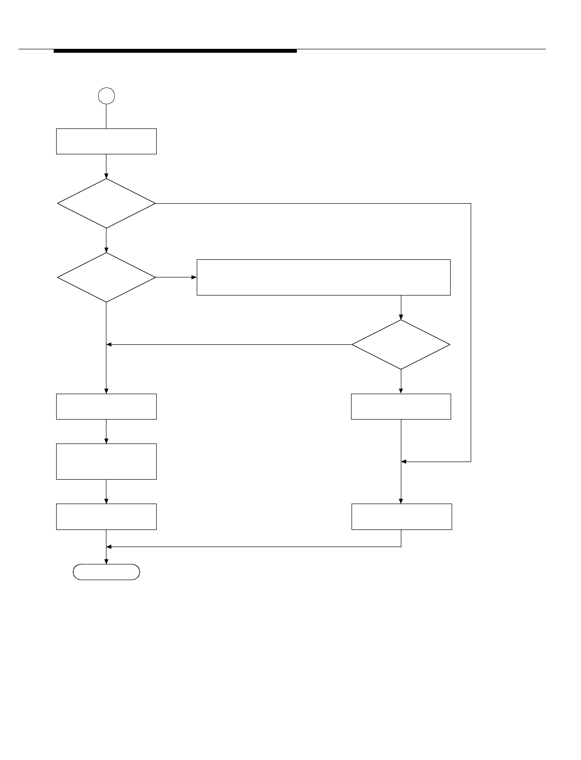
Lucent Technologies — Proprietary
See notice on first page
15-18 401-660-100 Issue 11 August 2000
Corrective Maintenance using MRA
Figure 15-2. Remove Flow of Voice Radio RCU, SBRCU, DRU, or EDRU
(Sheet 1 of 3)
Conditional remove of
voice radio (continued)
End
Return completion-code
message to technician.
Busy
Is radio
idle or busy
?
Does radio
become idle
?
If removed,
is OOS threshold
exceeded
?
No
Yes
Remove radio (place
unit out-of-service).
Set radio’s state in
equipment status table
to OOS-RMVD.
Idle
No
Yes
1
From
Sheet 1
For ECP R6.0 and Later: Attempt to handoff calls to another radio
of the same technology in the same sector; poll periodically to see
if radio is idle. Maximum waiting period is 5 minutes.
MRA blocks radio’s trunk(s).
*
Abort. Return error-code
message to technician.
*
Unblock radio’s trunk(s).
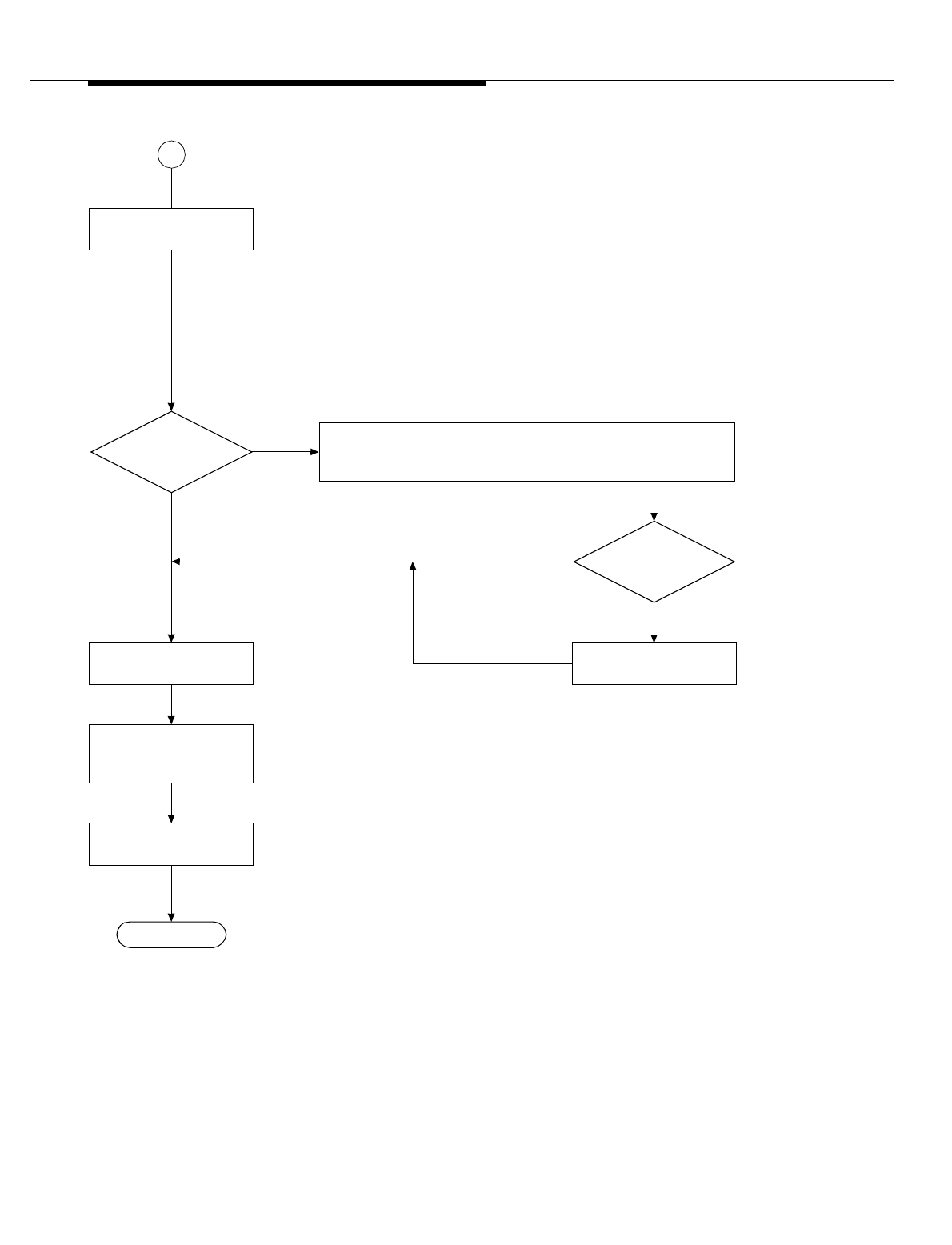
Lucent Technologies — Proprietary
See notice on first page
401-660-100 Issue 11 August 2000 15-19
Corrective Maintenance using MRA
Figure 15-3. Remove Flow of Voice Radio RCU, SBRCU, DRU, or EDRU
(Sheet 3 of 3)
Unconditional remove of
voice radio (continued)
Busy
Is radio
idle or busy
?
Does radio
become idle
?
No
Yes
Remove radio (place
unit out-of-service).
Set radio’s state in
equipment status table
to OOS-RMVD.
Idle
End
2
From
Sheet 1
Drop calls.
Return completion-code
message to technician.
MRA blocks radio’s trunk(s).
*
For ECP R6.0 or later: Attempt to handoff calls to another radio of
the same technology in the same sector; poll periodically to see if
radio is idle. Maximum waiting period is 5 minutes.
*
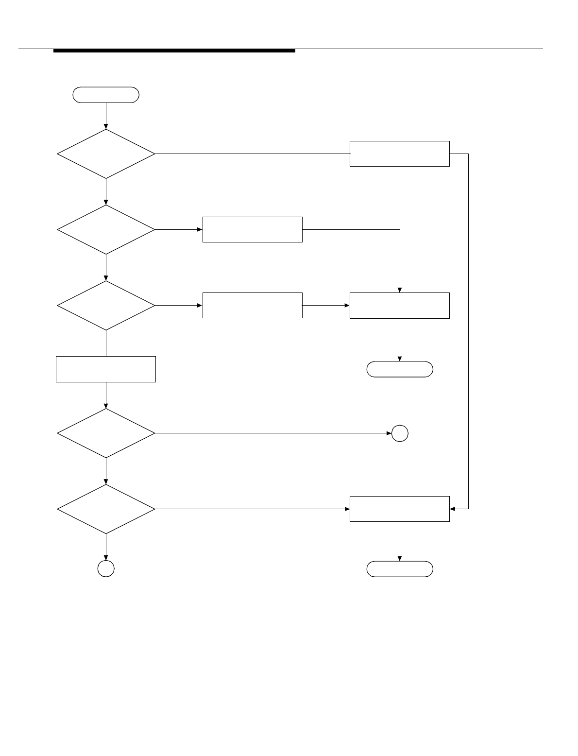
Lucent Technologies — Proprietary
See notice on first page
15-20 401-660-100 Issue 11 August 2000
Corrective Maintenance using MRA
Figure 15-4. Remove Flow of CCC (Sheet 1 of 3)
If removed,
is OOS threshold
exceeded
?
Remove CCC again and
tag unit OOS-RMVD.
Is CCC
in growth state
?
Is CCC
in OOS state
?
1To
Sheet 2
No
Ye s
No
Ye s Designated location has
no unit installed.
No
Ye s
Is CCC
unequipped
?
Start
End
End
Abort. Return error-code
message to technician.
Return completion-code
message to technician.
Cond
Uncond 2To
Sheet 3
No
Ye s
Is remove
request conditional or
unconditional
?
CCC is in active state.
Reset CCC; CCC remains
in growth state.
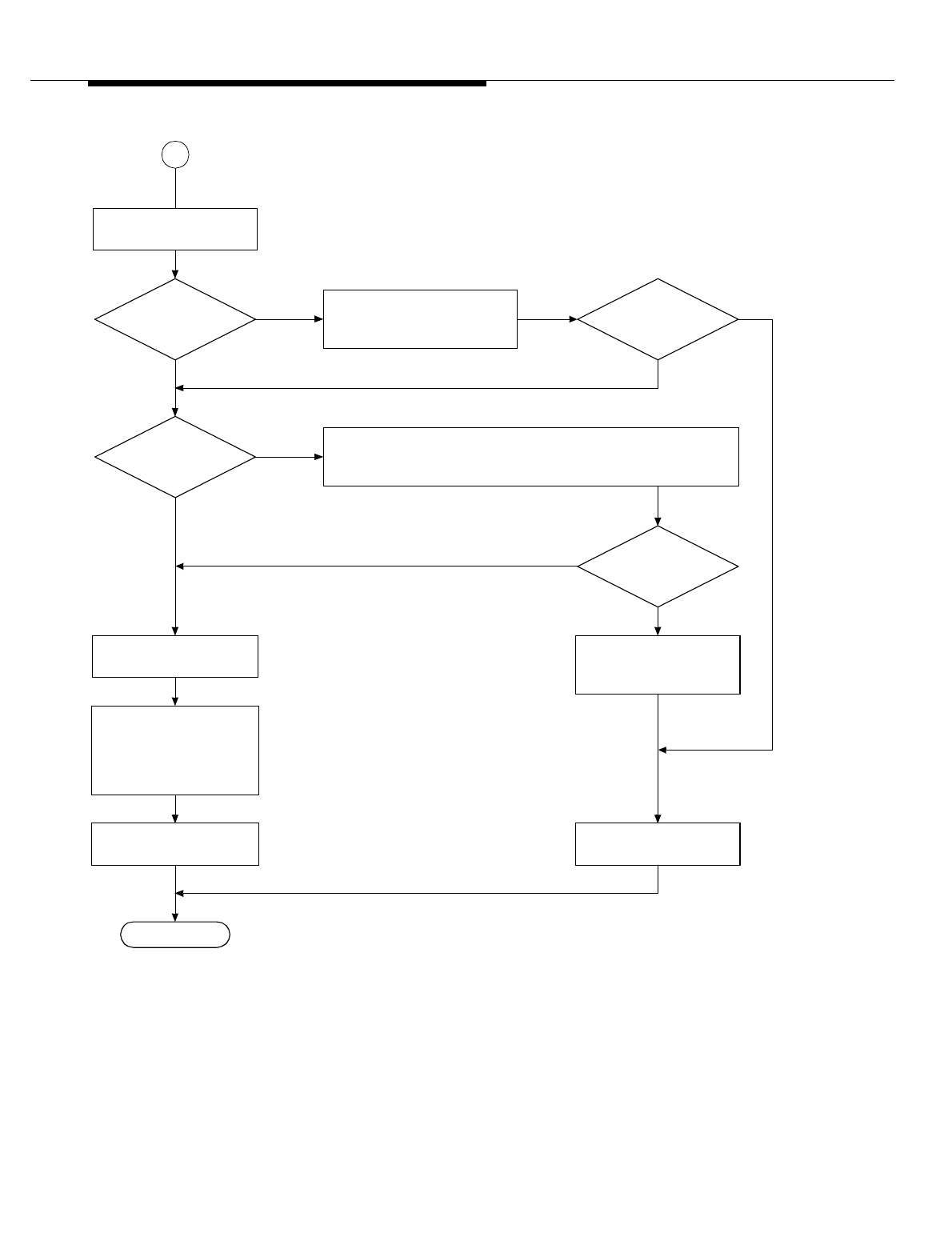
Lucent Technologies — Proprietary
See notice on first page
401-660-100 Issue 11 August 2000 15-21
Corrective Maintenance using MRA
Figure 15-5. Remove Flow of CCC (Sheet 2 of 3)
Is CCC
serving overhead
channels
?
Is migration
successful
?
Conditional remove of
CCC (continued)
End
Busy
Is CCC
idle or busy
?
Yes
Yes
1
From
Sheet 1
Abort. Return error-code
message to technician.
Does CCC
become idle
?
Unblock associated
CDMA cluster/ packet
pipe.
No
Return completion-code
message to technician.
Remove CCC (place unit
out-of-service).
Poll periodically to see if CCC is idle. Maximum waiting period is
5 minutes.
MRA blocks associated CDMA cluster/ packet pipe.
*
Attempt to migrate overhead
channels to another CDMA
cluster within subcell.
Set CCC’s state in
equipment status table
to OOS-RMVD; set any
active CCU under CCC
to OOS-POS.
Idle
No Yes
*
No
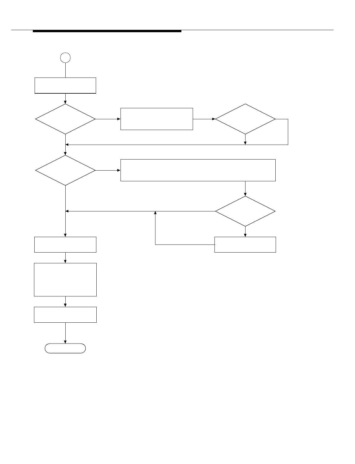
Lucent Technologies — Proprietary
See notice on first page
15-22 401-660-100 Issue 11 August 2000
Corrective Maintenance using MRA
Figure 15-6. Remove Flow of CCC (Sheet 3 of 3)
Is CCC
serving overhead
channels
?
Unconditional remove of
CCC (continued)
End
Busy
Is CCC
idle or busy
?
Ye s
Idle
No
Ye s
2
From
Sheet 1
MRA notifies ECP of any emergency call; currently,
technician cannot abort remove request.
Does CCC
become idle
?
Drop calls.
Is migration
successful
?
No **
Yes
If migration fails, MRA sends warning to ECP.
**
Return completion-code
message to technician.
Remove CCC (place unit
out-of-service).
Poll periodically to see if CCC is idle. Maximum waiting period is
5minutes.
MRA blocks associated CDMA cluster/ packet pipe.
*
Attempt to migrate overhead
channels to another CDMA
cluster within subcell.
Set CCC’s state in
equipment status table
to OOS-RMVD; set any
active CCU under CCC
to OOS-POS.
*
No
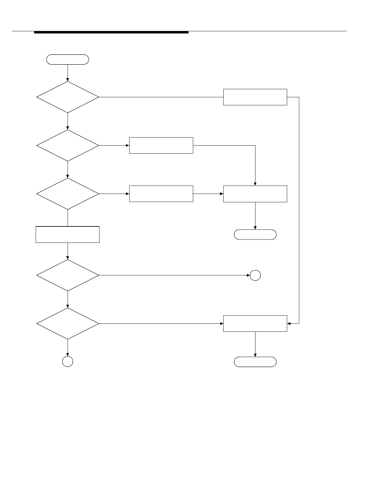
Lucent Technologies — Proprietary
See notice on first page
401-660-100 Issue 11 August 2000 15-23
Corrective Maintenance using MRA
Figure 15-7. Remove Flow of CCU (Sheet 1 of 3)
If removed,
is OOS threshold
exceeded
?
Remove CCU again and
tag unit OOS-RMVD.
Is CCU
in growth state
?
Is CCU
in OOS state
?
1To
Sheet 2
No
Ye s
No
Ye s Designated location has
no unit installed.
No
Ye s
Is CCU
unequipped
?
Start
End
End
Abort. Return error-code
message to technician.
Return completion-code
message to technician.
Cond
Uncond 2To
Sheet 3
No
Ye s
Is remove
request conditional or
unconditional
?
CCU is in active state.
Reset CCU; CCU remains
in growth state.
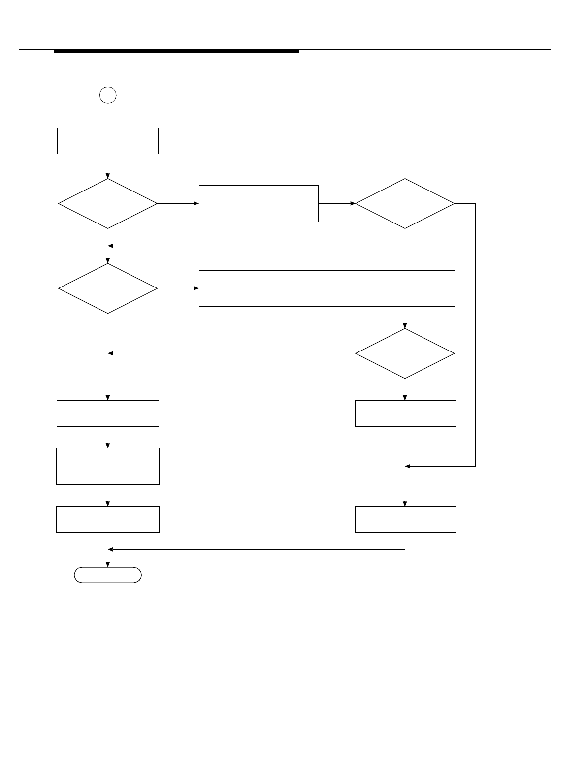
Lucent Technologies — Proprietary
See notice on first page
15-24 401-660-100 Issue 11 August 2000
Corrective Maintenance using MRA
Figure 15-8. Remove Flow of CCU (Sheet 2 of 3)
Is migration
successful
?
Conditional remove of
CCU (continued)
End
Busy
Is CCU
idle or busy
?
Is CCU
serving overhead
channels
?
No
Yes
Idle
No
Yes
1
From
Sheet 1
Abort. Return error-code
message to technician.
Does CCU
become idle
?
No
Yes
Return completion-code
message to technician.
Remove CCU (place unit
out-of-service).
Set CCU’s state in
equipment status table
to OOS-RMVD.
*
Poll periodically to see if CCU is idle. Maximum waiting period is
5 minutes.
Unblock CCU.
Attempt to migrate overhead
channels to another CCU
within subcell.
MRA blocks CCU from receiving calls.
*
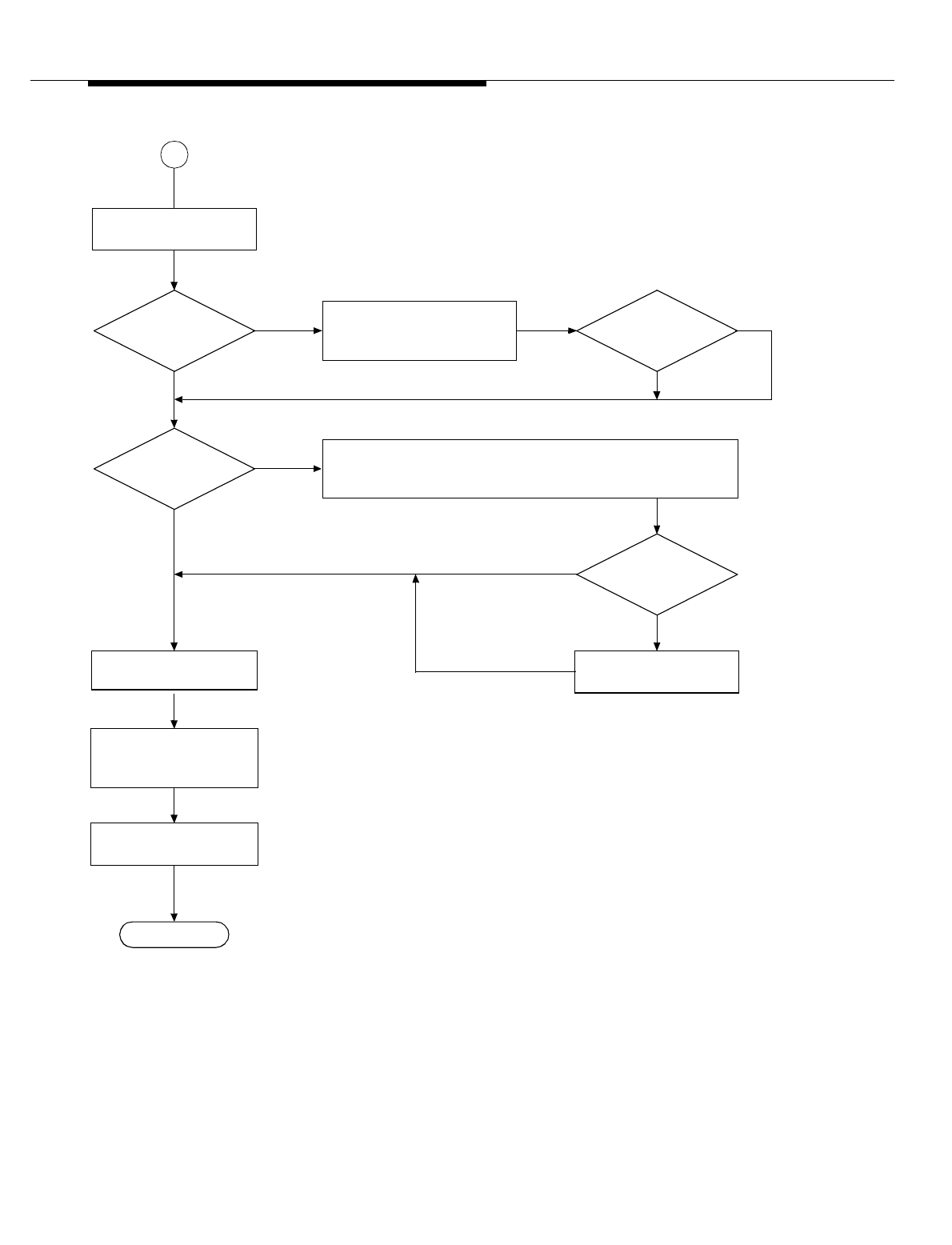
Lucent Technologies — Proprietary
See notice on first page
401-660-100 Issue 11 August 2000 15-25
Corrective Maintenance using MRA
Figure 15-9. Remove Flow of CCU (Sheet 3 of 3)
Is CCU
serving overhead
channels
?
Unconditional remove of
CCU (continued)
End
Busy
Is CCU
idle or busy
?
No
Ye s
Idle
No
Yes
2
From
Sheet 1
Does CCU
become idle
?
Drop calls.
Is migration
successful
?
No **
Yes
Return completion-code
message to technician.
Remove CCU (place unit
out-of-service).
Set CCU’s state in
equipment status table
to OOS-RMVD.
*
Poll periodically to see if CCU is idle. Maximum waiting period is
5minutes.
Attempt to migrate overhead
channels to another CCU
within subcell.
MRA notifies ECP of any emergency call; currently,
technician cannot abort remove request.
If migration fails, MRA sends warning to ECP.
**
MRA blocks CCU from receiving any calls.
*
Lucent Technologies — Proprietary
See notice on first page
15-26 401-660-100 Issue 11 August 2000
Corrective Maintenance using MRA
Figure 15-10. Remove Flow of BBA (Sheet 1 of 3)
Remove BBA again and
tag unit OOS-RMVD.
Is BBA
in growth state
?
Is BBA
in OOS state
?
No
Yes
No
Yes
No
Yes
Is BBA
unequipped
?
Start
BBA is in active or
standby state.
1To
Sheet 2
Designated location has
no unit installed.
End
Return completion-code
message to technician.
Reset BBA; BBA remains
in growth state.
Does BBA
have a mate
?
Standby
Active
Yes
No
Abort. Return error-code
message to technician.
32
Is mate
in standby state
?
Mate is in standby state. No
To
Sheet 2 To
Sheet 2
Yes
Is BBA
in active or standby
state
?
Lucent Technologies — Proprietary
See notice on first page
401-660-100 Issue 11 August 2000 15-27
Corrective Maintenance using MRA
Figure 15-11. Remove Flow of BBA (Sheet 2 of 3)
Is BBA
part of subcell
?
Is remove
request conditional or
unconditional
?
End
Return completion-code
message to technician.
1
From
Sheet 1
Abort. Return error-code
message to technician.
5
Update equipment status
table: BBA = OOS-RMVD.
Cond
Uncond
To
Sheet 4
Yes
2 3
From
Sheet 1
All BBA
mates in subcell in
standby state
?
Yes
No
No
Ye s
From
Sheet 1
Remove BBA (place unit
out-of-service).
Update equipment status
table: BBA = OOS-RMVD,
mate = active.
Remove BBAs (place
units out-of-service).
Update equipment status
table: BBAs = OOS-
RMVD, mates = active.
Remove BBA (place unit
out-of-service).
BBA is in standby state.
Switch BBAs to standby
& mates to active
(execute a switch).
Switch BBA to standby &
mate to active (execute a
switch).
(future)
If removed,
is OOS threshold
exceeded
?
4
To
Sheet 3
No

Lucent Technologies — Proprietary
See notice on first page
15-28 401-660-100 Issue 11 August 2000