Alcatel USA 8702-50 MDR-8000 User Manual MDR 8000 Radio Family Users Manual Issue 9
Alcatel USA Marketing, Inc. MDR-8000 MDR 8000 Radio Family Users Manual Issue 9
Contents
- 1. User manual 01
- 2. User manual 02
- 3. User manual 03
User manual 02

MDR-8000
Alcatel Part Number 3EM11931AA
3400 West Plano Parkway
Plano, Texas 75075-5813 U.S.A.
Issue 9, December, 2007
Microwave Digital Radios
Users Manual

NORTH AMERICA CUSTOMER SERVICE CENTER
24 HOURS PER DAY, 7 DAYS PER WEEK
PHONE the Call Center at
888-252-2832 (US and Canada)
or
613-784-6100 (International)
ALCATEL-LUCENT’S PRIMARY MISSION IS
SATISFYING OUR CUSTOMERS' QUALITY EXPECTATIONS.
The Call Center Agent (CSA)
Will help connect you with Technical Assistance (TAC)
Or assist you with a Repair and Return
• Phone-based technical support
• After-hour emergencies
• On-site technical support
• E-mail support ml-tac.support@alcatel-lucent.com
• Software and hardware upgrades
TAC
• Module repair
Repair and Return
• Training http://www.alcatel-lucent.com>support
– Technical Training
Other Services Offered
• Field Services
– Installation and test
• Customized and Comprehensive Service Agreements
• Registration http://www.alcatel-lucent.com>MyAccess
– Once registered
– From “MyAlcatel” go to “Alcatel Support Documentation”
–
Register for access to Documentation and e-mail Update notifications
For Product Change Notices (PCN), Product Documentations, etc.
– Software and Hardware upgrade documentation

Telephone Assistance, Normal Working Hours (CST 8am 5pm M-F)
TAC supports all Alcatel North America Microwave products. This includes routine questions and
emergency service.
Telephone Assistance, Emergency After-Hours
• Defined as loss of traffic, standby equipment, or network visibility on traffic-bearing systems.
• Available through our Customer Service Agents (CSA).
Contact Information Ask the Customer Service Agent (CSA) for a Microwave (MW) or a Network
Management Service engineer (NMS).
Please provide the following information to the Customer Service Agent (CSA):
• Last and First name
• Company name
• Telephone number
• City and state (Street address if applicable) or Site Name and Location
• Equipment type
• A brief description of the problem affecting their equipment
• Customer Priority: High, Medium, or Low.
• TL-9000 Severity as described below.
Creating a TAC Action Request (AR)
Critical
TL-9000 Severities Defined
Major
Minor Problems not classified as critical or major.
Problems severely affecting service, traffic, capacity, or network
management. They require immediate corrective action. (Ex.
Loss of network management capability, loss of traffic imminent
or existing).
Conditions seriously affecting system operation. They require
immediate attention. (Ex. processor outage, loss of standby
equipment, loss of remote access, or network managers).
TAC
Technical Assistance Center

T
able of Contents
TOC
-
1
Page
Section 1
General
1.1
INTRODUCTION
.............................................................................................
1
-
1
1.2
CONTENT
.......................................................................................................
1
-
1
Section 2
Operation
2.1
GENERAL
........................................................................................................
2
-
1
2.2
TURN-ON
........................................................................................................
2
-
1
2.3
USER SYSTEM INTERFACE (USI) PROVISIONING FUNCTION/OPERATION
......
2
-
2
2.4
OPERATING PROCEDURES
..............................................................................
2
-
2
2.4.1
Radio Receiver Manual Switching
.....................................................................
2
-
2
2.4.2
Radio Transmitter Manual Switching
.................................................................
2
-
5
2.4.3
Radio I/O Interface Manual Switching
..............................................................
2
-
5
2.4.4
MCS-11 Operation
..........................................................................................
2
-
7
2.4.5
Lamp Tests
.......................................................................................................
2
-
8
2.4.6
Alarm Checks
..................................................................................................
2
-
8
2.4.7
Orderwire Operation
.......................................................................................
2
-
8
2.4.8
Initiating Outgoing Orderwire Calls
..................................................................
2
-
8
2.4.9
Answering Incoming Orderwire Calls
................................................................
2
-
8
2.5
TURN-OFF PROCEDURE
...................................................................................
2
-
9
2.6
EMERGENCY OPERATION
..............................................................................
2
-
9
2.7
MODEM OPERATION
......................................................................................
2
-
9
2.8
CONTROLS, INDICATORS, TEST POINTS, AND CONNECTORS
.......................
2
-
9
Section 3
Interconnect
3.1
SECTION INTRODUCTION
..............................................................................
3
-
1
3.2
POWER CABLE CONNECTION
.......................................................................
3
-
1
3.3
PDU STRAPPING AND CONNECTIONS
...........................................................
3
-
4
3.4
SHELF/RACK ALARM CONNECTION
..............................................................
3
-
5

Page
TOC
-
2
3.5
MDR-8000 SYNCHRONOUS REPEATER CONNECTIONS
................................
3
-
5
3.5.1
Low Capacity DS1 Radios
................................................................................
3
-
7
3.5.2
High Capacity DS3 Radios
...............................................................................3 - 7
3.5.3
High Capacity OC3 Radios
..............................................................................3 - 7
3.5.4
MDR-8000 Synchronous Repeater Compatibility Matrix
.....................................3 - 8
3.5.5
MDR-8000 Synchronous Repeater Cables
.........................................................3 - 8
3.6
DS1 CONNECTIONS (J303 IN AND J304 OUT)
..............................................3 - 9
3.7
DS1 REPEATER (J314 ON ONE SHELF TO J314 ON SECOND SHELF)
............3 - 11
3.8
DS3 LBO STRAPPING AND CONNECTIONS
.................................................3 - 12
3.9
DS3 LBO DS3 BNC CONNECTIONS (J21 THROUGH J26)
.............................3 - 13
3.10
DS3 LBO WAYSIDE DS1 CONNECTIONS (J201 IN AND J202 OUT)
.............3 - 14
3.10.1
Wayside DS1 Terminal
..................................................................................3 - 14
3.10.2
Wayside DS1 Repeater
..................................................................................3 - 14
3.11
DS3 REPEATER (J401 ON ONE SHELF TO J401 ON SECOND SHELF)
............3 - 16
3.12
FIBER OPTIC CABLE CONNECTIONS
.............................................................3 - 18
3.12.1
2 or 4 Fiber Management Panel
.....................................................................3 - 19
3.12.2
2x4 Fiber Switched Management Panel
..........................................................3 - 19
3.13
OC3/STM-1 AUX INTERFACE BOARD WAYSIDE DS1 CONNECTIONS
(J201 IN AND J202 OUT)
..............................................................................3 - 22
3.13.1
Wayside DS1 Terminal
..................................................................................3 - 22
3.13.2
Wayside DS1 Repeater
..................................................................................3 - 22
3.14
OC3/STM-1 REPEATER
(J203 ON ONE SHELF TO J203 ON SECOND SHELF)
...................................3 - 23
3.15
ETHERNET CABLE CONNECTIONS
...............................................................3 - 24
3.15.1
Automatic MDI/MDI-X Configuration
...............................................................3 - 24
3.15.2
Crossover Cable Option
.................................................................................3 - 25
3.15.3
Terminal Connections
.....................................................................................3 - 29
3.15.4
Repeater Connections
....................................................................................3 - 33
3.16
USI/CONTROLLER CABLE CONNECTION TO LAPTOP (J301)
.........................3 - 35
3.17
SERVICE CHANNEL CONNECTIONS
............................................................3 - 37
3.17.1
2-Wire Handset Connection
...........................................................................3 - 37
3.17.2
Service Channels Provisioning Options
............................................................3 - 39
3.17.3
Audio 1, Audio 2 (J316, J317) Connections
...................................................3 - 39
3.17.4
RS-232-1, RS-232-2 (J312, J313)
....................................................................3 - 43

Page
TOC - 3
3.18
MCS-11 CONNECTIONS
..............................................................................3 - 44
3.18.1
MCS-11 Master (J307)
...................................................................................3 - 45
3.18.2
MCS-11 Repeater-to-Spur Daisy Chain Connection (J308/J309)
.......................3 - 48
3.18.3
MCS-11 Spur Connection (J310)
....................................................................3 - 56
3.19
TMN CONNECTIONS
...................................................................................3 - 58
3.19.1
Installing Module
...........................................................................................3 - 58
3.19.2
Typical Interconnect Scenarios
........................................................................3 - 60
3.19.3
Front Access Connectors
.................................................................................3 - 64
3.19.4
MATING CABLES
..........................................................................................3 - 67
3.19.5
Front Panel Craft Interface Connector J5
..........................................................3 - 68
3.20
ELMC (J315, J318)
........................................................................................3 - 69
3.21
FOREIGN ALARM INTERFACE (J305)
.............................................................3 - 72
3.22
ALARM, STATUS, AND CONTROLS INTERCONNECT
.....................................3 - 75
3.22.1
Controller Bus
................................................................................................3 - 77
3.22.2
Control Inputs
................................................................................................3 - 77
3.22.3
Station Alarm Inputs/TBOS Interface
...............................................................3 - 77
3.22.4
Station Alarm Wiring
.....................................................................................3 - 78
3.22.5
Relay Alarm/Status Outputs
............................................................................3 - 79
3.22.6
Relay Control Outputs
....................................................................................3 - 80
Section 4 Initial Turnup
4.1
SECTION INTRODUCTION
..............................................................................4 - 1
4.2
RECOMMENDED SEQUENCE
.........................................................................4 - 1
4.3
SECURITY MANAGEMENT
..............................................................................4 - 2
4.4
LOAD MDR-8000 SOFTWARE ON PC
..............................................................4 - 2
4.5
TURN-ON PROCEDURE
...................................................................................4 - 4
4.6
ESTABLISH COM PORT
....................................................................................4 - 4
4.7
TEST PROCEDURES
..........................................................................................4 - 7
4.8
PROVISIONING RADIO
...................................................................................4 - 7
4.9
PROVISION ETHERNET FACILITY
....................................................................4 - 29
4.9.1
Auto-Negotiation
............................................................................................4 - 30
4.10
PROVISION DS1 FACILITY
.............................................................................4 - 32

Page
TOC - 4
Section 5 Maintenance
5.1
INTRODUCTION
.............................................................................................5 - 1
5.2
MAINTENANCE PHILOSOPHY
.........................................................................5 - 2
5.3
RECOMMENDED TEST EQUIPMENT
................................................................5 - 4
5.4
OPTIONAL TEST EQUIPMENT
..........................................................................5 - 4
5.5
PERSONAL COMPUTER (PC)/LAPTOP
..............................................................5 - 5
5.6
MDR-8000 ALARMS
........................................................................................5 - 7
5.7
ALARM MONITORING AND INSPECTION
.......................................................5 - 7
5.8
RECOMMENDED PERIODIC CHECKS
..............................................................5 - 8
5.9
RADIO TROUBLESHOOTING
...........................................................................5 - 8
5.9.1
Troubleshooting USI Alarms
..............................................................................5 - 8
5.9.2
Troubleshooting RCVR Lockup Problems
............................................................5 - 8
5.9.3
Troubleshooting Performance Screen Errors
.......................................................5 - 9
5.10
ETHERNET-SPECIFIC TROUBLESHOOTING
......................................................5 - 24
5.10.1
Troubleshooting Using Ethernet I/O Interface Module Front Panel Indicators ......5 - 24
5.11
TMN-SPECIFIC TROUBLESHOOTING
..............................................................5 - 26
5.12
MODULE REPLACEMENT
...............................................................................5 - 29
5.13
POWER SUPPLY REMOVAL AND REPLACEMENT
............................................5 - 32
5.14
CONTROLLER REMOVAL AND REPLACEMENT
...............................................5 - 33
5.15
DS3 I/O INTERFACE REMOVAL AND REPLACEMENT
.....................................5 - 37
5.16
OC3/STM-1/ETH I/O INTERFACE REMOVAL AND REPLACEMENT
................5 - 39
5.17
XMTR REMOVAL AND REPLACEMENT
...........................................................5 - 40
5.18
XMT CRYSTAL OSCILLATOR FREQUENCY CORRECTION
................................5 - 46
5.19
XMTR OUTPUT LEVEL CHECK (NO PA)
...........................................................5 - 47
5.20
IN-SERVICE XMTR CARRIER NULL ADJUSTMENT
USING SPECTRUM ANALYZER
.......................................................................5 - 48
5.21
XMTR OUTPUT LEVEL CALIBRATION
...............................................................5 - 56
5.22
RCVR REMOVAL AND REPLACEMENT
............................................................5 - 61
5.23
RCV CRYSTAL OSCILLATOR FREQUENCY CORRECTION
................................5 - 64
5.24
PA REMOVAL AND REPLACEMENT
................................................................5 - 65
5.25
PA OUTPUT LEVEL CALIBRATION
...................................................................5 - 67
5.26
CHANGING FREQUENCY
.............................................................................5 - 72
5.27
CLEANING
...................................................................................................5 - 72

TOC - 5
Section 6 User Guide
6.1
INTRODUCTION
.............................................................................................6 - 1
6.2
ANALOG SCREEN
..........................................................................................6 - 1
6.2.1
PA (DC MON)
.................................................................................................6 - 1
6.2.2
TX (PWR MON)
...............................................................................................6 - 1
6.2.3
ATPC Voltage
..................................................................................................6 - 1
6.2.4
RX (RSL 1) dBm
................................................................................................6 - 1
6.2.5
RX (EYE MON)
................................................................................................6 - 1
6.2.6
RX (AFC MON)
................................................................................................6 - 1
6.2.7
Battery Voltage
................................................................................................6 - 1
6.3
DS1/E1 RADIO PERFORMANCE SCREEN
........................................................6 - 3
6.3.1
Repeater CRC Err Sec
......................................................................................6 - 3
6.3.2
Radio Severe Err Sec
........................................................................................6 - 3
6.3.3
Radio Outage Sec
............................................................................................6 - 3
6.3.4
Radio A and B Outage Sec
..............................................................................6 - 3
6.3.5
Radio CRC Err Sec
...........................................................................................6 - 3
6.3.6
Radio CRC Errors
.............................................................................................6 - 3
6.3.7
Radio Internal BER
............................................................................................6 - 3
6.3.8
Radio Average BER
..........................................................................................6 - 3
6.4
DS3 RADIO PERFORMANCE MONITORING SCREEN
......................................6 - 5
6.4.1
Line 1-3 DS3 Errors
..........................................................................................6 - 5
6.4.2
Line 1-3 DS3 BER
.............................................................................................6 - 5
6.4.3
Radio Errors
.....................................................................................................6 - 5
6.4.4
Radio Error Seconds
.........................................................................................6 - 5
6.4.5
Radio Severe Error
...........................................................................................6 - 5
6.4.6
Radio BER
.......................................................................................................6 - 5
6.5
OC3/STM-1 RADIO PERFORMANCE MONITORING SCREENS
........................6 - 6
6.5.1
OC3/STM-1 Errors
..........................................................................................6 - 6
6.5.2
OC3/STM-1 Error Seconds
..............................................................................6 - 6
6.5.3
OC3/STM-1 Severe Error Seconds
...................................................................6 - 6
6.5.4
OC3/STM-1 Severe Error Frame
.......................................................................6 - 6
6.5.5
OC3/STM-1 BER
.............................................................................................6 - 6
6.5.6
Line 1-3 DS1 Error Seconds
..............................................................................6 - 6
6.5.7
Radio Errors
.....................................................................................................6 - 6

TOC - 6
6.5.8
Radio Error Seconds
........................................................................................6 - 8
6.5.9
Radio Severe Error
...........................................................................................6 - 8
6.5.10
Radio BER
.......................................................................................................6 - 8
6.6
ETHERNET RADIO PERFORMANCE MONITORING SCREEN
.............................6 - 8
6.6.1
RF Receive
.......................................................................................................6 - 8
6.6.2
GPF Receive
....................................................................................................6 - 9
6.7
ETHERNET PERFORMANCE MONITORING SCREEN
........................................6 - 9
6.7.1
IN (To RF Transmit)
...........................................................................................6 - 9
6.7.2
OUT (From RF Receive)
...................................................................................6 - 10
6.8
DS1/E1 RADIO CONTROL SCREEN
..............................................................6 - 11
6.8.1
In-Service Controls
.........................................................................................6 - 11
6.8.2
System Loopback Controls
..............................................................................6 - 11
6.8.3
User Controls
.................................................................................................6 - 11
6.8.4
DS1 Line Loopback Controls
...........................................................................6 - 11
6.9
DS3 RADIO CONTROL SCREEN
....................................................................6 - 13
6.9.1
In-Service Controls
.........................................................................................6 - 13
6.9.2
System Loopback Controls
..............................................................................6 - 13
6.9.3
User Controls
.................................................................................................6 - 14
6.9.4
Wayside DS1 Line Loopback Controls
.............................................................6 - 14
6.10
OC3/STM-1 RADIO CONTROL SCREEN
........................................................6 - 16
6.10.1
In-Service Controls
.........................................................................................6 - 16
6.10.2
System Loopback Controls
..............................................................................6 - 16
6.10.3
User Controls
.................................................................................................6 - 16
6.11
ETHERNET RADIO CONTROL SCREEN
...........................................................6 - 18
6.11.1
In-Service Controls
.........................................................................................6 - 18
6.11.2
User Controls
.................................................................................................6 - 18
6.11.3
System Loopback
...........................................................................................6 - 19
6.11.4
DS1 Line Loopback
........................................................................................6 - 21
6.11.5
Inventory Screen
............................................................................................6 - 24

4-1
The information contained in this section is a summary of the section
with the same title, but not the same section number, on the enclosed
CD. “Refer to Cd” is used throughout this section to refer the reader to
the detail information on the CD. Go to this section on the CD for inter-
active links to the detail information referred to in this section.
4INITIAL TURNUP
4.1 SECTION INTRODUCTION
This section describes the procedures required to turn up the MDR-8000 Microwave
Digital Radios after installation.
This provisioning part of the section describes provisioning options available with the
MDR-8000 software application. Provisioning allows for the definition, editing, and storing
of specific functions. The MDR-8000 provides the ability to provision equipment and facili-
ties through a series of Windows™-based screens and messages. The Provisioning menu
lists equipment and functions which may be provisioned. You should use only those provi-
sioning screens that are applicable to your radio.
4.2 RECOMMENDED SEQUENCE
Perform the following initial turnup procedures in sequence:
A. Install software on PC.
Software installed at the factory before delivery should not be overwrit-
ten by downloading to the radio controller at initial turnup. Refer to
Maintenance section on the attached CD for procedure to upgrade exist-
ing software.
B. Turn on the radio.
C. Establish communication between radio and USI computer.
Saving provisioning on disk provides a reference for any future provi-
sioning changes.
D. Provision radio.
Note
Note
Note

4-2
4.3 SECURITY MANAGEMENT
A password is not required to operate the MDR-8000. The radio is
shipped without a password and if a password is desired, it must be
entered using the Change Password screen. Once entered initially, the
password must be entered each time the user wants to access the provi-
sioning screens (level 1 password required) or download software (level
2 password required).
The MDR-8000 application software offers user password security management using two
different levels of passwords. User security deals with access level assigned to specific
users. The level of user security affects the type and number of commands an individual
user may execute. This prevents an unqualified user’s access to high-level commands.
Level 1 password allows the user to perform all tasks except downloading software. Level 2
password allows access to all functions and is the highest level.
4.4 LOAD MDR-8000 SOFTWARE ON PC
Before operating the user system interface (USI) for the first time, the programs contained
on the CD ROM must be installed on the PC. The installation process configures the PC for
its unique requirements and prepares it to run the program.
A. Insert CD ROM disk into PC.
B. On Windows desktop, double click on My Computer icon. My Computer
window displays.
C. In My Computer window, click on CD ROM icon. Files window displays
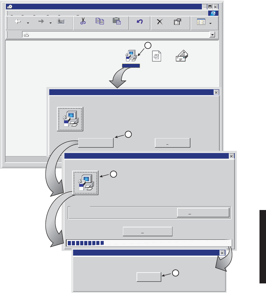
D. See Figure 4 - 1. Follow directions and load USI software on PC.
Note
4-3
Figure 4 - 1 Load USI Software on PC
Address
File
D:\
C:\
Edit View Go
Favorites
Help
Setup cannot install system files or update shared files if they are in use.
Before proceeding, we recommend that you close any application you may
be running.
MDR-8000 Universal USI Setup
Exit SetupOK
Directory:
c:\winuniversal_xx
Begin the installation by clicking the button below.
Click this button to install MDR-8000 Universal USI software to the specified
destination directory.
Exit Setup
Change Directory
MDR-8000 Universal USI Setup
OK
MDR-8000 Universal USI Setup was completed successfully.
MDR-8000 Universal USI Setup
OK
setup.1st win11_xx.CABsetup.exe
Back Forward Cut Copy Paste
Delete Properties
UndoUp Views
1DOUBLE CLICK
2CLICK HERE
CLICK HERE
3
4CLICK HERE
END
DOWN-
LOAD
STARTING
DOWN LOAD
COPYING
FILES
LOADING
FILES
LMW-4023
10/16/05

4-4
4.5 TURN-ON PROCEDURE
For user safety, user should become familiar with locations of power
distribution units and circuit breakers associated with the MDR-8000
radio.
Perform the following procedure to turn on the radio.
A. On power supply module, set PA
ON/O
FF switch to OFF. Yellow PA OFF
indicator will light.
B. On power supply module, set POWER ON 1/OFF 0 switch to ON 1.
C. On power supply module, set PA ON/OFF switch to ON. Yellow PA OFF
indicator will turn off.
Until both the local and farend radios in the hop are turned on and
operating properly and the RF path has been established, alarm condi-
tions will exist.
D. Observe CHAN ALM indicator on RCVR module is lit.
E. Wait for RCVR to lock on frequency. When RCVR is locked on frequency
(approximately 5 to 30 seconds), CHAN ALM indicator on RCVR module will
turn off.
F. Verify all front panel alarm indicators on radio shelf are off. If not, refer to
Maintenance section for troubleshooting.
4.6 ESTABLISH COM PORT
Establish communication between the USI computer and the controller in the radio.
Disable infrared option on laptop (if equipped) to prevent disrupting
communication on com port.
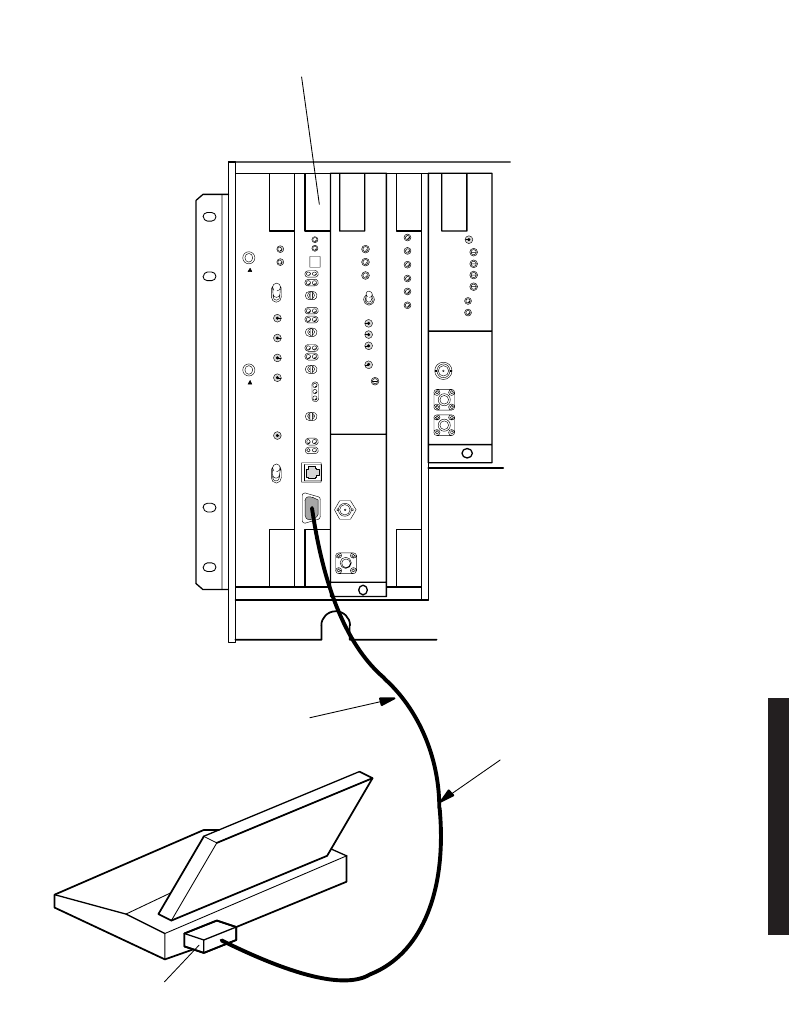
A. Connect RS-232 interface cable between USI connector on controller and PC.
See Figure 4 - 2.
B. On Windows desktop, click on Start icon. Program menu displays.
Only one COM port can be used at a time.
Note
Note
Note
Note
4-5
Figure 4 - 2 USI Computer Hookup
MW211–0066–1
101598
AE–37( )
CNTLR
C1
RS–232C PORT
RS–232C
INTERFACE CABLE
USI
TERMINAL
TO CONNECTOR J301
(CONNECTS TO
AE–37 CONTROLLER)
MDR–8000
SHELF
4-6
C.
On Program menu, click on Win USI program. Win USI screen displays with
message
COMMUNICATING
to indicate PC is communicating with the radio
controller. If
COMMUNICATION DOWN
message is displayed, perform
procedure shown on Figure 4 - 3 to change
COM
port.
D.
STOP
. This procedure is complete.
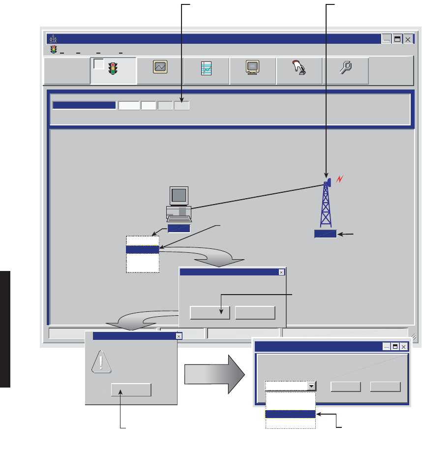
Figure 4 - 3 Communications Port Setup
Alcatel User Interface
File View Setup Options
LOCAL STATUS ALARM
Communicating***
ELMC Addre s s:
R101
F6
Performance
Alarm Status Analog Monitor
F5
Station Alarm
F7
Provisioning
F9
User Control
F8F4
Tuesday, Janu
LMW-7232
02/02/04
ELMC
ADDRESS
Thursday, November 30, 2000 1:44:19 PM USI Version 1.20 Controller Version 1.20
R101 LCL FAR RMT
Co m 1 R101
Would you like to save this setting?
Save *.ini File
Invalid port number
Com Port Error
OK
OK Cancel
co m 1
co m 2
co m 3
co m 4
OK Cancel
com 1
com 2
com 3
com 4
com 3
Pl
ease select a valid com-port in the
following
picklist
CLICK HERE.
CONFIRMATION MESSAGE
DISPLAYS.
CLICK HERE
TO SAVE
SELECT ANOTHER
COM PORT
CLICK HERE. COMM PORT
SELECTION SCREEN DISPLAYS.
DOUBLE CLICK HERE TO
OPEN ALARM STATUS
SCREEN
DOUBLE CLICK HERE TO
OPEN ELMC ADDRESS
LIST
LMW-1023
01/12/07
If COM port is correct
ALM/status screen
displays. If not, Comm
port error message
displays.

4-7
4.7 TEST PROCEDURES
The radio has been properly aligned and tested at the factory before shipment eliminating
the need for testing after initial turn-up. The only time testing and/or adjustment is
required is after a maintenance action such as removal and replacement procedure and/or
constant alarms requiring corrective maintenance action. The completed maintenance
action procedure(s) will reference any required test procedure(s).
4.8 PROVISIONING RADIO
Changes to provisioning do not have to be made in any particular order.
Open radio provisioning screens. On main screen, double click on tower icon. Status and
alarm screen displays. Click on Provisioning. Check current provisioning and change as
required. See Figure 4 - 4 for recommended sequence.
Note
4-8
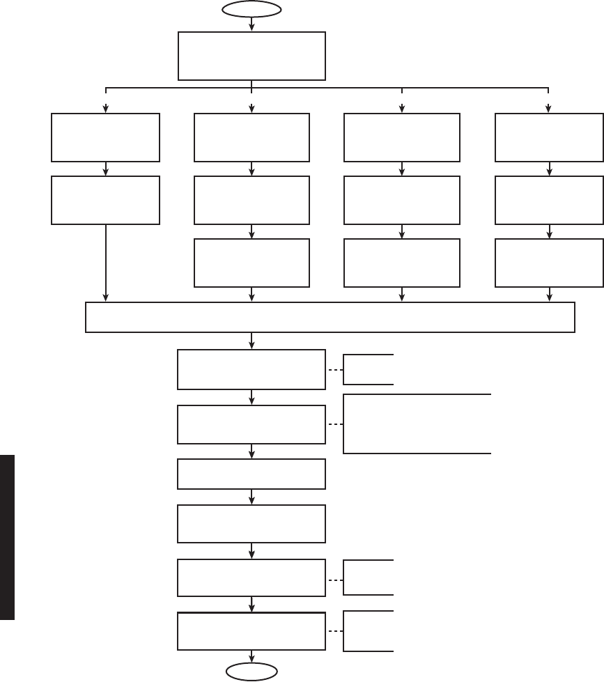
Figure 4 - 4 Provisioning Sequence
FIG 4-8
DS3 RADIO
CONFIG
PROVISIONING
FIG 4-5
DS1/E1, DS3, OC3/STM-1, ETH
RADIO CONFIG
PROVISIONING
FIG 4-9
DS3
FACILITIES
PROVISIONING
FIG 4-6
DS1/E1 RADIO
CONFIG
PROVISIONING
FIG 4-7
DS1/E1
FACILITIES
PROVISIONING
FIG 4-11
OC3/STM-1 RADIO
CONFIG
PROVISIONING
FIG 4-12
OC3/STM-1
FACILITIES
PROVISIONING
FIG 4-13
OC3/STM-1 RADIO
WAYSIDE DS1 FACILITIES
PROVISIONING
FIG 4-14
ETH RADIO
CONFIG
PROVISIONING
FIG 4-15
ETH
FACILITIES
PROVISIONING
FIG 4-17
ETH
DS1 FACILITIES
PROVISIONING
FIG 4-10
DS3 RADIO
WAYSIDE DS1 FACILITIES
PROVISIONING
SAVE PROVISIONING
FIG 4-27
CONTROL NAMES
PROVISIONING
START
OPTIONAL
ENTRY
OPTIONAL
INCLUDES PROVISIONING FOR:
AUDIO
RS-232
MCS-11
TMN
MDR-1287
Issue 8
03/10/07
FIG 4-26
ELMC REMOTE TIME-OUT
CONSTANT PROVISIONING
FIG 4-28
STATION ALARM NAMES
PROVISIONING
END
OPTIONAL
ENTRY
FIG 4-25
ELMC PROVISIONING
DS1/E1 DS3 OC3/STM-1 ETH
FIG 4-19 THRU 4-24
SERVICE CHANNEL
PROVISIONING
FIG 4-18
ENTER PASSWORDS
4-9
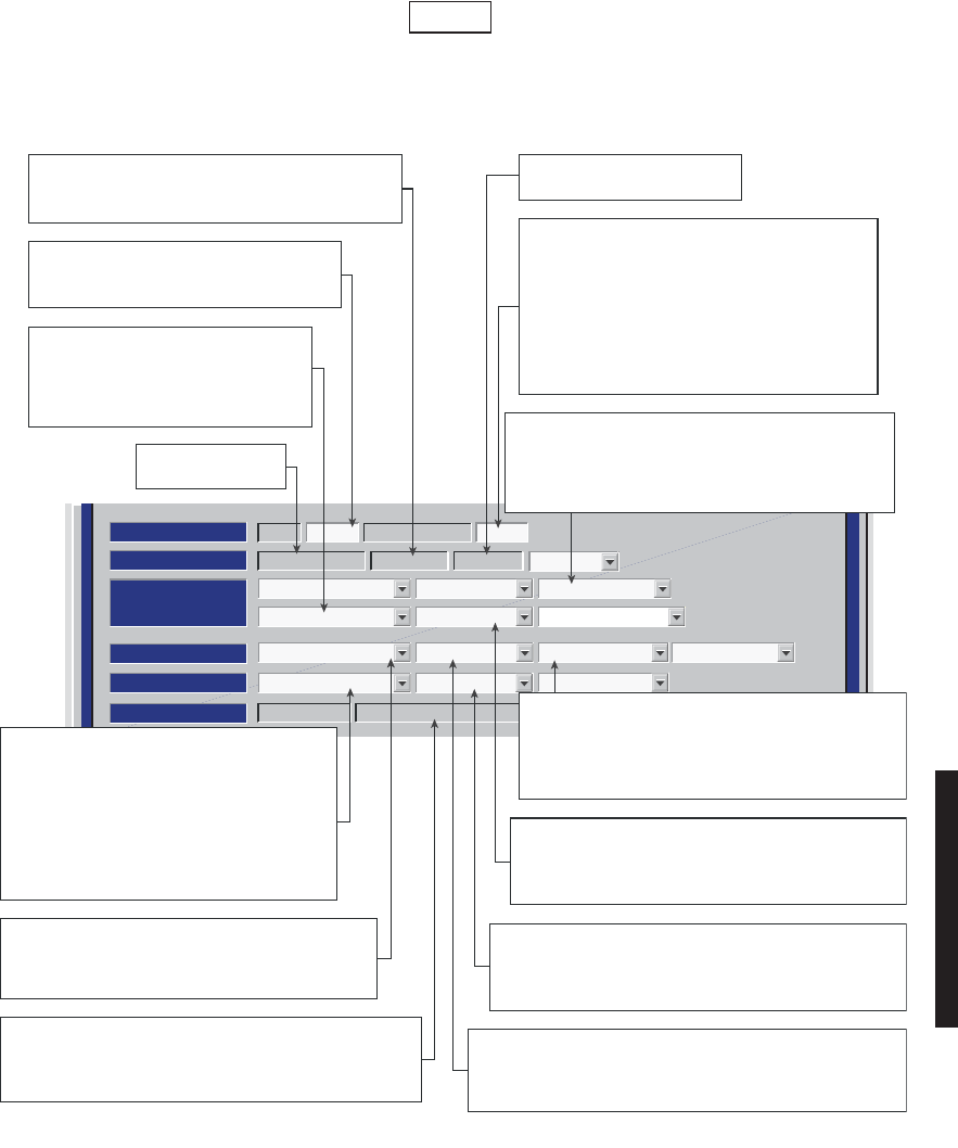
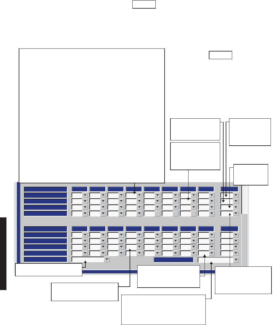
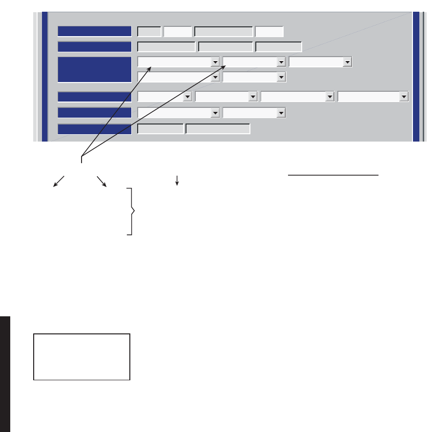
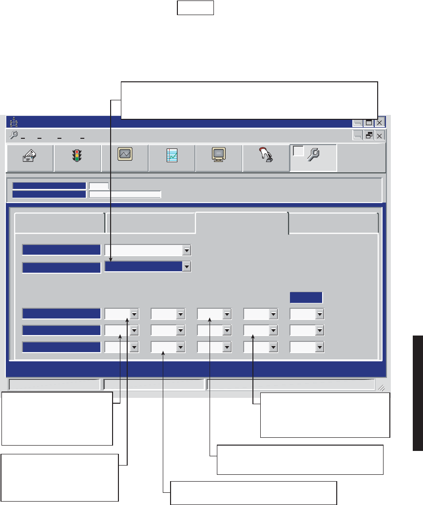
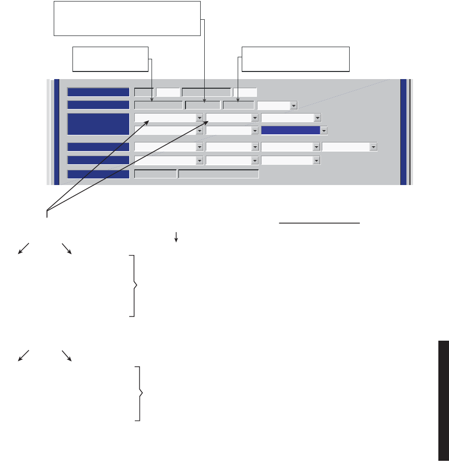
Screen for OC3 radio is shown. DS1/E1, DS3, SNMP, and ETH radio
configuration is similar.
Figure 4 - 5 DS1/E1, DS3, OC3/STM-1, ETH Radio Configuration Provisioning (Sheet 1 of 2)
Note
ATPC Disable NO PA
RADIO CONFIG:
Hot-Standby Tx Hot-Standby Rx TERMINAL
10-11 GHz
SYSTEM ALARM
Major/Minor Relays ON/NO Station Alarm 13-16
Degrade Enable
RSL Alarm Enable
RSL-Sw Enable
Eye BER=1x10⁻⁶
RCV SWITCHING:
RADIO TYPE:
MDR-8000 OC3 OC-3 128 TCM
OPTIONS:
Stat/Prov/WaySideOption Key:
SYSTEM ID:
R112 Disable
RADIO LINK ID:ELMC:
Relay Card Present
Displays modulation scheme.
Not provisionable.
Displays radio type.
Not provisionable.
MDR-1030
09/02/04
Displays number of lines available as determined
by
capacity key. Changing number of lines requires
changing
capacity key.
Select DISABLE or double click to enable.
(00 displays). Enter 2-digit number between 00
and 99 as identification for radio RCV/XMT pair.
Use for frequency coordination in congested
areas that have nearby transmitters at same
frequency with same modulation. ID must be
same at both ends of Hop. If RCV ID does not
match ID received from far-end XMTR, a USI
alarm and rack alarm are generated.
Select RSL-Sw Enable to enable automatic
receiver switching based on
RSL. When enabled,
receiver switches if:
1. On-LINE RCV RSL is below RCV AGC
threshold, and
2. Off-LINE RCV RSL is abobe RCV AGC
threshold.
Select RSL-Sw Disable to disable automatic
receiver switching.
Select Major/Minor to trigger major alarm on any
alarm on ON-LINE side and minor alarm on any alarm
on OFF-LINE side. Select Visual/Audible to trigger
rack alarm on any alarm on ON-LINE side.
Select Station Alarm 13-16 to enable Station Alarm
13-16 inputs to relay INFTC. When external TBOS is
wired to radio, select TBOS Display 1-8 to enable
TBOS drivers on controller and select a TBOS display
(1-8) to view.
Select approximate error rate at which eye closure alarm
activates and switching occurs:
EYE BER=1X10⁻⁵, 1X10⁻⁶,
1X10⁻⁷, 1X10⁻⁸ or select
Eye BER Disable
to activate
alarms at approximately 1x10⁻⁶ without receivers switching.
Select A&B PA Present if shelf is equipped with A&B
PAs, or A OR B PA ONLY if shelf is equipped with only
one PA, or NO PA if shelf is not equipped with PA.
Unequipped PA alarms are disabled.
Select Relays ON/NO (normally open-high impedance)
or Relays ON/NC (normally closed-ground) on alarm for
alarms/status outputs, or Relays OFF. Refer to relay
interface in Theory section for deatils.
Displays ELMC option key type installed on controller. STAT
(STATUS)/PROV (remote provisioning)/wayside (with wayside
DS1 monitoring). Not provisionable. Changing display
requires changing option key.
Select TERMINAL, REPEATER, RING TERMINAL
or RING REPEATER from a dropdown list. Select
REPEATER if traffic and service channel (four rails
of X/Y data) are being transported between J314 of
both shelves.
Enable or disable automatic power
control (ATPC) function. Select ATPC
Disable, ATPC Enabled,
or
ATPC
with Timeout
from dropdown list.
See Sheet 2 of 3 for details.
Backspace to delete current address and
enter 5-digit remote rack address. See
Figure 6-11 for details.
4-10
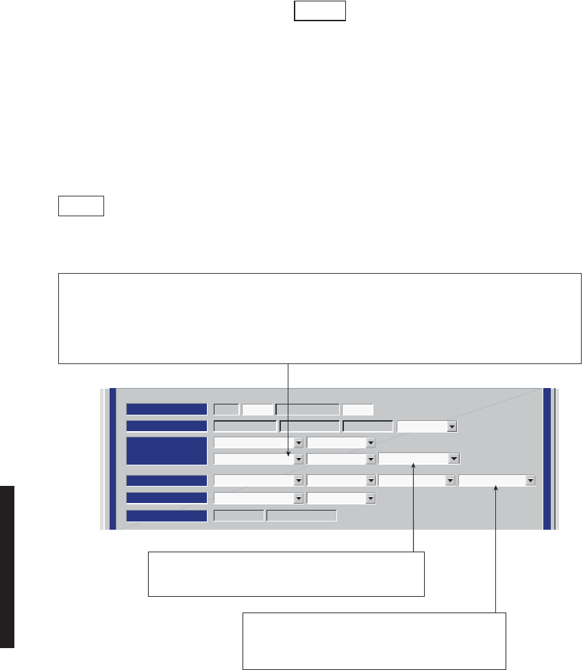
Screen shown is for DS1 Radio. E1, DS3, OC3/STM-1, and ETH radio
configuration provisioning is similar. Changes to provisioning do not
have to be made in any particular order.
Figure 4 - 5 DS1/E1, DS3, OC3/STM-1, ETH Radio Configuration Provisioning (Sheet 2 of 2)
Note
ATPC Enabled A&B PA Present
RADIO CONFIG:
HS Tx/HS Rx TERMINAL
6-8 GHz
SYSTEM ALARM
Visual/Audible RELAYS ON/NO Station Alarm 13-16 RSL Alarm Enable
RSL-SW Disable BER Disable
RCV SWITCHING:
RADIO TYPE:
MDR-8000 DS1 16 LINES 128 TCM
OPTIONS:
Stat/Prov/WaySideOption Key:
SYSTEM ID:
TEST1 Disable
RADIO LINK ID:ELMC:
Relay Card Present
SELECT ATPC OR ATPC T/O ENABLE AUTOMATIC XMT POWER CONTROL (ATPC) FUNCTION. WHEN PROVISIONED
ATPC OR ATPC T/0, ONE RCVR OUT-OF-LOCK CAUSES HIGH POWER ATPC FOR 10 SECONDS EVERY ONE MINUTE.
IF BOTH RCVRS ARE OUT-OF-LOCK, ATPC GOES TO HIGH POWER AND STAYS AT HIGH POWER UNTIL ONE RCVR
(REVERTS TO ONE RCVR OUT-OF-LOCK MODE) OR BOTH RCVRS LOCK. WHEN PROVISIONED ATPC T/O (TIMEOUT),
IF CMD PATH IS LOST, ATPC GOES TO HIGH POWER FOR FIVE MINUTES THEN GOES TO LOW POWER. THEN, EVERY
HOUR, ATPC GOES HIGH FOR 10 SECONDS AND THEN GOES TO LOW POWER. THIS CONTINUES UNTIL THE CMD
PATH IS RESTORED. SELECT DISABLE TO DISABLE ATPC FUNCTION.
NOTES
1. ATPC T/O IS A CMD PATH FUNCTION PERFORMED AT XMTR.
2. ATPC TRACKS RCVR WITH HIGHEST LEVEL.
3. LOW POWER ATPC IS 10dB DOWN FROM HIGH POWER.
MDR-1031
12/06/07
SELECT RSL Alarm Enable TO ENABLE ALARM ON USI
ALARM AND STATUS SCREEN WHEN RSL DROPS
BELOW THRESHOLD. SELECT RSL Alarm Disable TO
INHIBIT ALARM.
SELECT Relay Card Present IF SHELF IS EQUIPPED WITH
A RELAY INTFC MODULE. SELECT Relay Card Not Present
IF SHELF IS NOT EQUIPPED WITH A RELAY INTFC CARD.
4-11
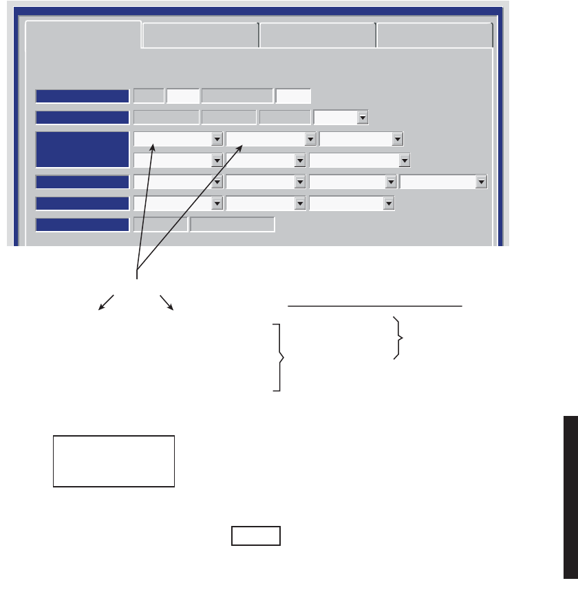
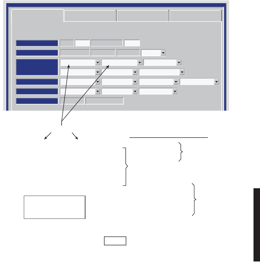
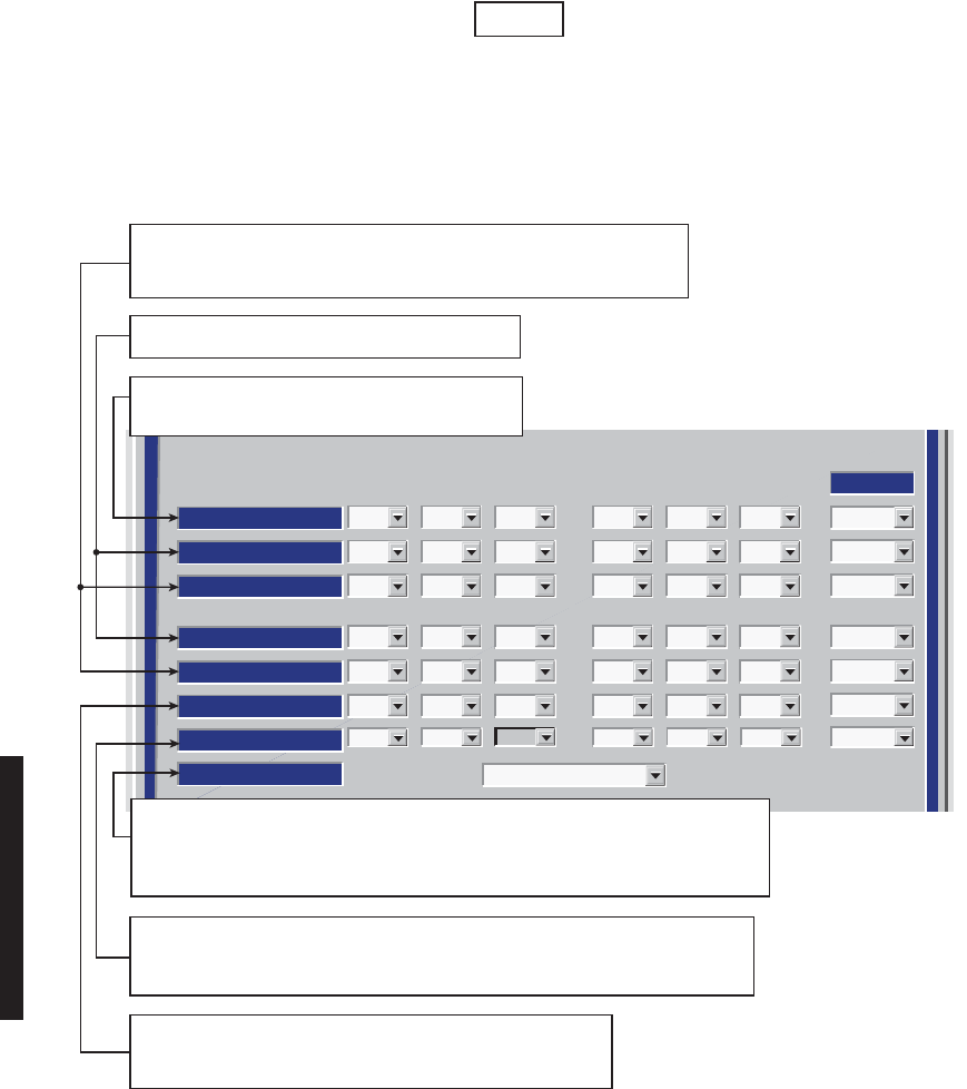
Figure 4 - 6 DS1/E1 Radio Configuration Provisioning
Radio Configuration Service Channel DS1 Facilities
Friday, April 8, 2005 9:16:47 AM USI Version 3.01 MDR-8000 3-DS3 Controller Version P3.03
MDR-8000 DS1 16 LINES 128 TCM
RADIO TYPE:
ELMC: DS105 RADIO LINK ID: Disable
SYSTEM ID:
RADIO CONFIG:
Non-Standby Tx Hot-Standby Rx
TERMINAL
6GHz
ATPC Enabled
A&B PA Present
Relay Card Present
Option Key:
Stat/Prov/WaySide
OPTIONS:
SYSTEM ALARM:
Visual/Audible
RELAYS ON/NO
EYE BER Disable Degrade Disable
Station Alarm 13-16
RSL Alarm Enable
RCV SWITCHING:
Disable AGC
None
Non-Standby Tx
Hot-Standby Tx
Freq-Diversity Tx
None
Non-Standby Rx
Hot-Standby Rx
Space-Diversity Rx
Freq-Diversity Rx
+
NS Tx/NS Rx
NS Tx/HS Rx
NS Tx/SD Rx
HS Tx/HS Rx (See Example 1)
HS Tx/SD Rx (See Example 2)
FREQ DIV (Refer to CD).
(Refer to CD)
NS = Non-Standby
HS = Hot-Standby
SD = Space Diversity
SELECT ONE ON EACH
Resulting Configurations
=
Note
Any combination can be selected. Select Prov Save and an
Invalid Configuration box/message displays if combination
selected results in an invalid configuration.
MDR-1157
03/10/07
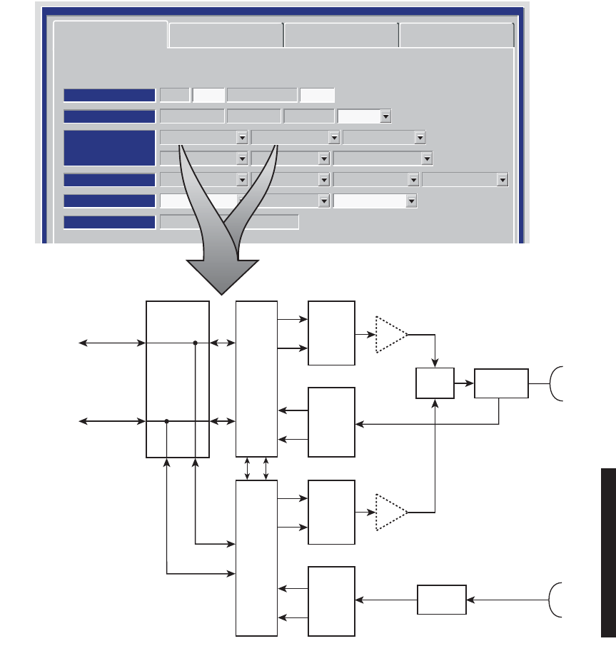
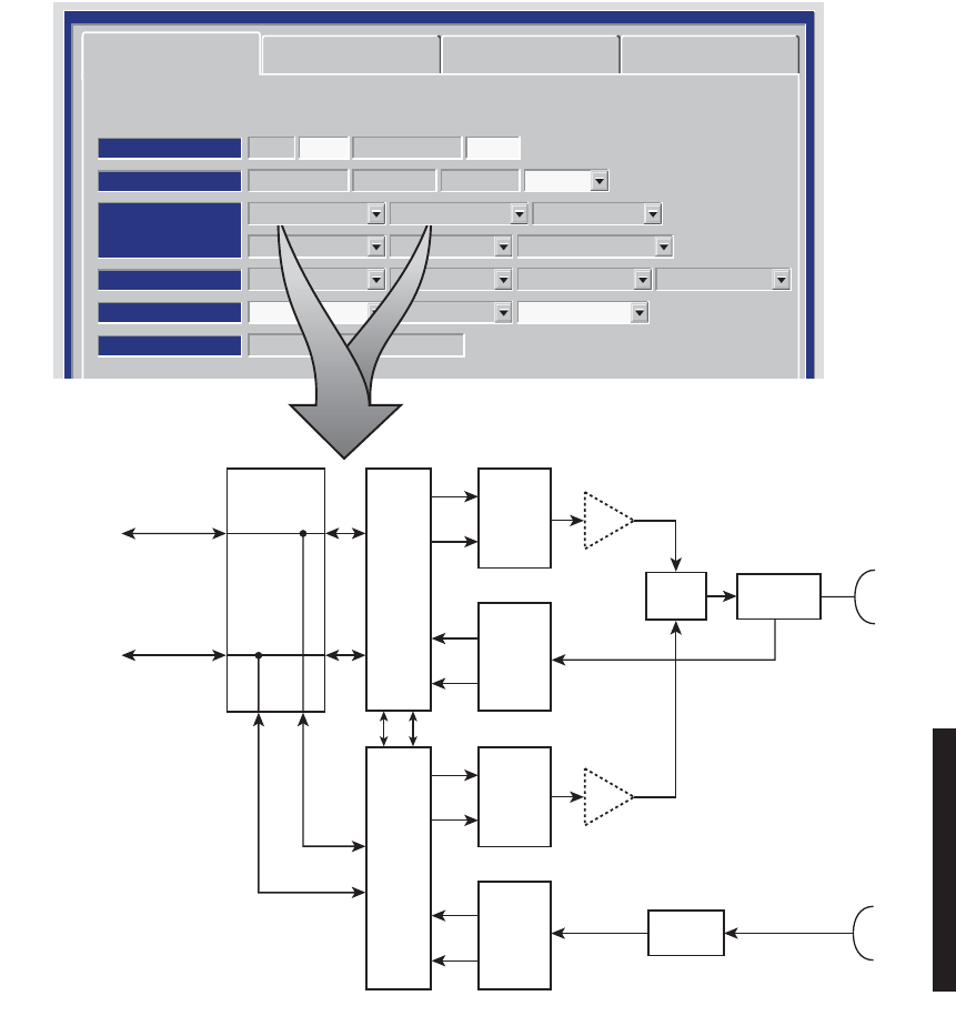
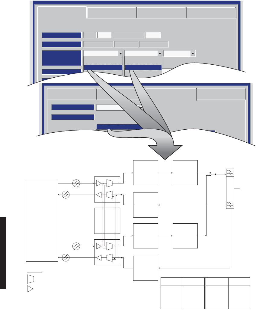
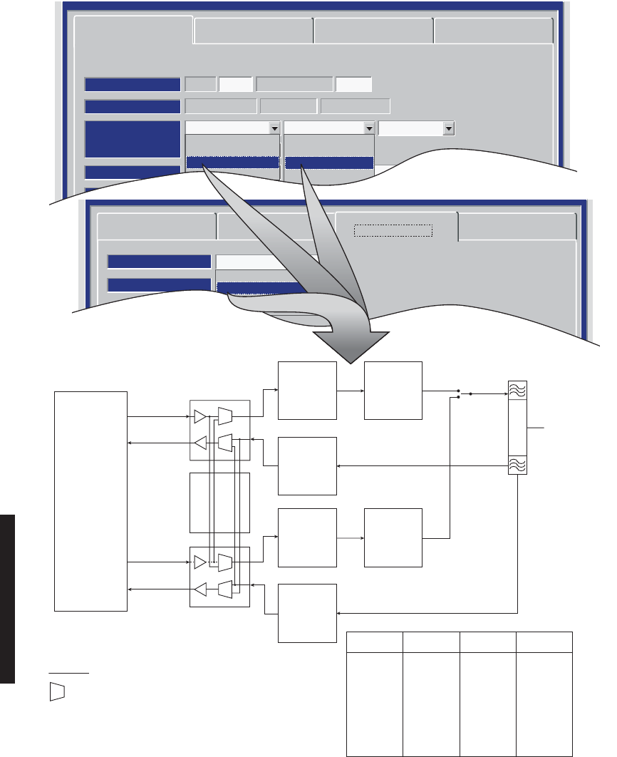
4-12
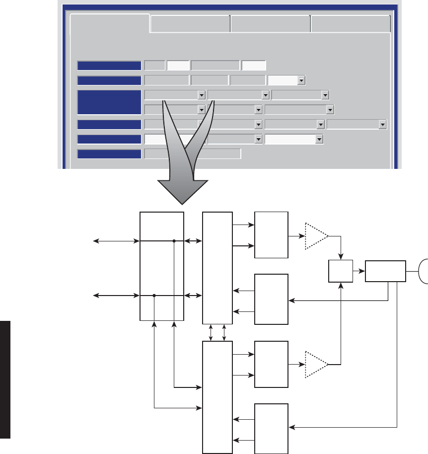
DS1/E1 PROVISIONING EXAMPLE 1: HS Tx/HS Rx
Radio Configuration Service Channel DS3 Facilities
Friday, April 8, 2005 9:16:47 AM USI Version 3.01 MDR-8000 3-DS3 Controller Version P3.03
MDR-8000 DS1 16 LINES 128 TCM
RADIO TYPE:
ELMC: DS105 RADIO LINK ID: Disable
SYSTEM ID:
RADIO CONFIG:
Hot-Standby Tx Hot-Standby Rx
Repeater
U6-8GHz
ATPC Disable
A&B PA Present
Relay Card Present
Option Key:
Stat/Prov/WaySide
OPTIONS:
SYSTEM ALARM:
Major/Minor
RELAYS ON/NO
EYE BER Disable Degrade Disable
Station Alarm 13-16
RSL Alarm Disable
RCV SWITCHING:
RSL-Sw Disable
Hot-Standby Tx Hot-Standby Rx
I
Q
Rx
Rs
Rx
Rs
I/O
INTFC
A
I/O
INTFC
B
XMTR
A
I
Q
XMTR
B
DIPLEXER
PA
XMT
SW
(OPTIONAL)
PA
(OPTIONAL)
RF
IN/OUT
RCVR
A
RCVR
B
DX DATA/
CLK/SYNC
MX DATA/
CLK/SYNC
LBO
2ND MDR-8000
SHELF (RPTR)
X-CONN (TERM)
OR
2ND MDR-8000
SHELF (RPTR)
SC/SYNC
DS1/E1
1-16
MDR-1161
04/20/05
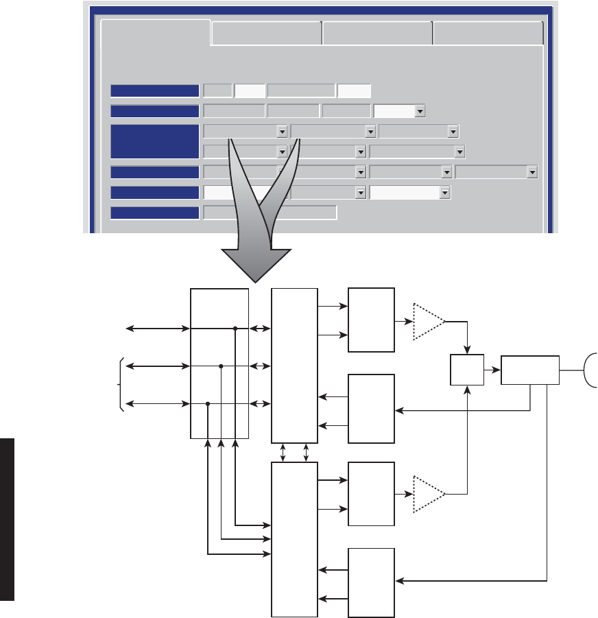
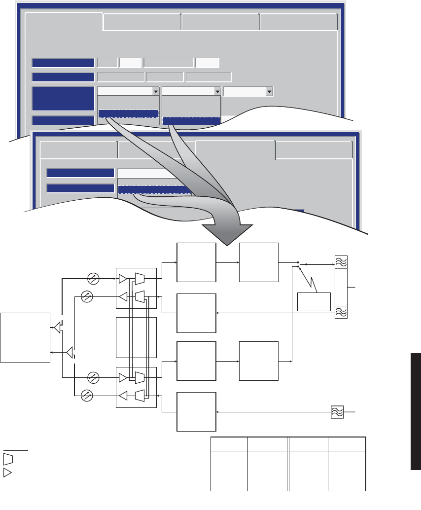
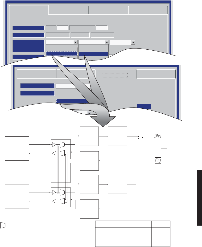
4-13
DS1/E1 PROVISIONING EXAMPLE 2: HS Tx/SD Rx
Radio Configuration Service Channel DS1 Facilities
Friday, April 8, 2005 9:16:47 AM USI Version 3.01 MDR-8000 3-DS3 Controller Version P3.03
MDR-8000 DS1 16 LINES 128 TCM
RADIO TYPE:
ELMC: DS105 RADIO LINK ID: Disable
SYSTEM ID:
RADIO CONFIG:
Hot-Standby Tx Space Diversity Rx
Repeater
U6-8GHz
ATPC Disable
A&B PA Present
Relay Card Present
Option Key:
Stat/Prov/WaySide
OPTIONS:
SYSTEM ALARM:
Major/Minor
RELAYS ON/NO
EYE BER Disable Degrade Disable
Station Alarm 13-16
RSL Alarm Disable
RCV SWITCHING:
RSL-Sw Disable
Hot-Standby Tx Space Diversity Rx
I
Q
Rx
Rs
Rx
Rs
I/O
INTFC
A
I/O
INTFC
B
XMTR
A
I
Q
XMTR
B
DIPLEXER
PA
XMT
SW
(OPTIONAL)
PA
(OPTIONAL)
RF
IN/OUT
RCVR
A
RCVR
B
RCV
FILTER
RF
IN
FROM
SECOND
ANTENNA
LBO
SC/SYNC2ND MDR-8000
SHELF (RPTR)
X-CONN (TERM)
OR
2ND MDR-8000
SHELF (RPTR)
DS1/E1
1-16
DX DATA/
CLK/SYNC
MX DATA/
CLK/SYNC
MDR-1135
04/20/05
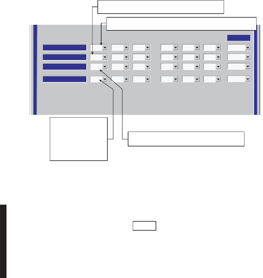
4-14
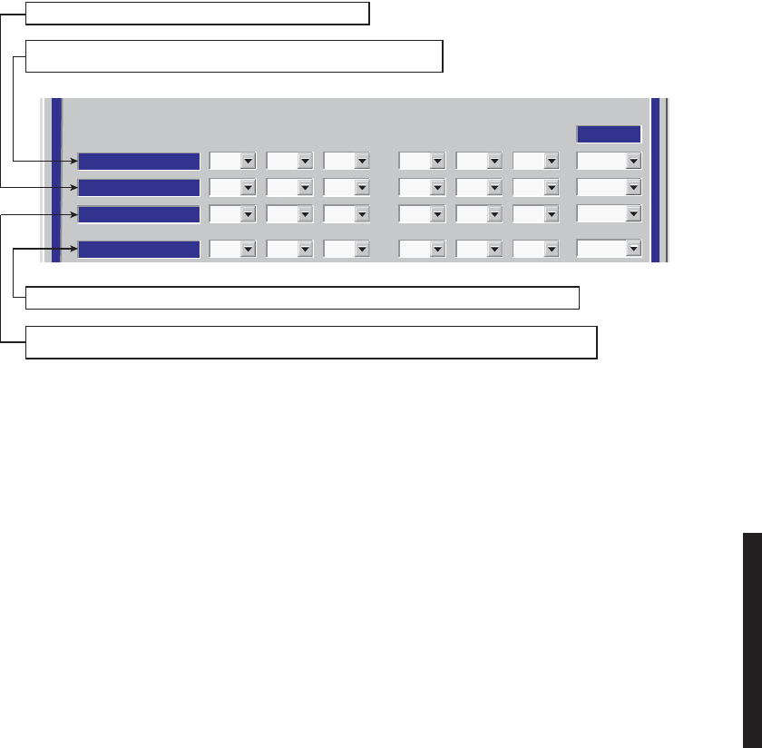
Figure 4 - 7 DS1/E1 Facilities Provisioning
LMW-3020
04/04/07
DS1 LINE LENGTH
LINES
INSERT CHANNEL
DROP CHANNEL
LINE CODING
31 2 4
ON
ON
AMI
ON
ON
AMI
OFF
OFF
AMI
OFF
OFF
AMI
75 6
OFF
OFF
AMI
OFF
OFF
AMI
OFF
OFF
AMI
8
OFF
OFF
AMI
Select All
AIS INHIBIT
OFF OFF OFF OFF OFF OFF OFF OFF
LINE
INSERT CHANNEL
DROP CHANNEL
LINE CODING
11910 12
OFF
OFF
AMI
OFF
OFF
AMI
OFF
OFF
AMI
OFF
OFF
AMI
1513 14
OFF
OFF
AMI
OFF
OFF
AMI
OFF
OFF
AMI
16
OFF
OFF
AMI
Select All
AIS INHIBIT
OFF OFF OFF OFF OFF OFF OFF OFF
AIS SIGNAL
ALL ONES
0-150
SELECT
ALL 1s
OR
ALL 0s
AIS
DATA FORMAT FOR ALL LINES. SELECT
ON
OR
OFF
. WHEN
SET TO ON,
AIS INSERTION
IS INHIBITED ON SELECTED
DS1/E1.
SELECT
AMI
OR
B8ZS
CODING
FOR EACH DS1 LINE. E1 LINE
CODING IS ALWAYS HDB3.
FOR EACH LINE,
SELECT
ON
TO DROP
LINE OR
OFF
TO
DISABLE LINE AND
ALARMS.
SELECT
ON
TO DROP
ALL LINES OR
OFF
TO
DISABLE ALL LINES
AND ALARMS.
SELECT
ON
TO
INSERT ALL
LINES OR
OFF
TO
DISABLE ALL LINES
AND ALARMS.
SELECT
ON
TO INHIBIT AIS
INSERTION ON ALL LINES.
SELECT
OFF
TO ENABLE
AIS INSERTION ON ALL
LINES.
SELECT
AMI
OR
B8ZS
CODING FOR
ALL DSI LINES
FOR ALL DS1 LINES, SELECT RANGE
THAT MATCHES ACTUAL DISTANCE
TO CROSS-CONNECT
0-150 (TEO OFF),
150-330 (TEO ON), 330-480 (TEO OFF)
OR
480-660 (TEO ON)
FT. FOR E1, NO DIS-
TANCE
IS DISPLAYED.
SELECTING
ON
INSERTS LOCAL DATA AND TURNS ON THE
SELECTED CHANNEL.
SELECTING
OFF
TURNS OFF LOCAL DATA INSERT AND TURNS OFF
LINE INPUT ALARM REPORTING ON THE SELECTED CHANNEL.
SELECTING
NM
INSERTS AN AIS SIGNAL AND TURNS OFF LINE
INPUT ALARMS ON THE SELECTED CHANNEL.
•
ALWAYS SELECT ON WHEN LOCAL DATA IS INSERTED.
•
ALWAYS SELECT OFF AT EITHER A TERMINAL OR A
NON-PROTECTED REPEATER WHEN LOCAL DATA IS NOT
INSERTED.
•
ONLY SELECT NM ON UNUSED CHANNELS AT PROTECTED
REPEATERS.
UNUSED CHANNELS ARE DEFINED AS CHANNELS THAT HAVE
NEITHER LOCALLY INSERTED DATA NOR PASS-THRU DATA ACROSS
THE REPEATER CABLE. SELECT OFF IF LOCAL DATA IS NOT
INSERTED AND THE CHANNEL HAS PASS-THRU DATA ACROSS THE
REPEATER CABLE (NOTE: SELECTING NM IN THIS CASE WILL
CAUSE THE DATA FROM THE REPEATER TO BE OVERWRITTEN
WITH AN AIS SIGNAL PRIOR TO TRANSMISSION).
USING THE REPEATER CABLE TO PASS DS1 DATA ON CHANNELS
5-16 IS NOT RECOMMENDED ON MDR-8000 RADIOS. PASSING THE
DATA THROUGH ON THESE CHANNELS WILL PREVENT
INDEPENDENT SWITCHING BETWEEN THE DS1 I/O AND THE RADIO
TRANSMITTERS. THE DATA SHOULD BE DROPPED AND
REINSERTED AT EACH REPEATER NODE.
Note
The term "LINE" is used to describe an input/output
signal at DS1/E1 rate (1.544 MB/S 2.043 MB/S). The
term "CHANNEL" is used to describe a multiplexed
signal, at a higher rate than DS1/E1. The inserted
channel is output of multiplexer circuit. The dropped
channel is input to demultiplexer circuit. The
multiplexer and demultiplexer circuits are located on
I/O interface module.
Note
If installation at both ends of a hop are complete except for connecting to customer inputs/outputs and it is desirable to have an
alarm-free system, alarm reporting on the incomplete connections can be disabled temporarily through provisioning. You can
communicate over the hop even if you do not have the radio connected to customer DS1 inputs; however, you will alarm unless
you select
OFF
to disable
INSERT CHANNEL
(located on the USI DS1 Facilities screen) for all equipped lines. Disabling the DS1
insert function disables both the lines and alarm reporting for the lines. After all customer connections are complete, alarm
reporting can be restored to normal. To restore alarm reporting to normal, set
INSERT CHANNEL
on DS1 Facilities screen to
ON
.
4-15
Figure 4 - 8 DS3 Radio Configuration Provisioning
Radio Configuration Service Channel DS3 Facilities
WaySide DS1 Facilities
Friday, April 8, 2005 9:16:47 AM USI Version 3.01 MDR-8000 3-DS3 Controller Version P3.03
MDR-8000 DS3 3 LINES 64 QAM
RADIO TYPE:
ELMC: DS305 RADIO LINK ID: Disable
SYSTEM ID:
RADIO CONFIG:
Non-Standby Tx Hot-Standby Rx
TERMINAL
6GHz
ATPC Enabled
A&B PA Present
Relay Card Present
Option Key:
Stat/Prov/WaySide
OPTIONS:
SYSTEM ALARM:
Visual/Audible
RELAYS ON/NO
EYE BER Disable Degrade Disable
Station Alarm 13-16
RSL Alarm Enable
RCV SWITCHING:
Disable AGC
None
Non-Standby Tx
Hot-Standby Tx
Freq-Diversity Tx
SIMPLEX NS Tx
SIMPLEX HS Tx
None
Non-Standby Rx
Hot-Standby Rx
Space-Diversity Rx
Freq-Diversity Rx
SIMPLEX NS Rx
SIMPLEX HS/SD Rx
+
NS Tx/NS Rx
NS Tx/HS Rx
NS Tx/SD Rx
HS Tx/HS Rx (See Example 1)
HS Tx/SD Rx (See Example 2)
FREQ DIV
HS Tx/NS Rx
SIMPLEX NS Tx
SIMPLEX HS Tx
SIMPLES NS Rx
SIMPLEX HS/SD Rx
NS = NON-STANDBY
HS = HOT-STANDBY
SD = SPACE DIVERSITY
SELECT ONE ON EACH
Resulting Configurations
=
Note
Any combination can be selected. Select Prov Save and an
Invalid Configuration box/message displays if combination
selected results in an invalid configuration.
(Refer to CD)
(Refer to CD)
MDR-1129
03/10/07
4-16
DS3 PROVISIONING EXAMPLE 1: HS Tx/HS Rx
Radio Configuration Service Channel DS3 Facilities
WaySide DS1 Facilities
Friday, April 8, 2005 9:16:47 AM USI Version 3.01 MDR-8000 3-DS3 Controller Version P3.03
MDR-8000 DS3 3 LINES 64 QAM
RADIO TYPE:
ELMC: DS305 RADIO LINK ID: Disable
SYSTEM ID:
RADIO CONFIG:
Hot-Standby Tx Hot-Standby Rx
Repeater
U6-8GHz
ATPC Disable
A&B PA Present
Relay Card Present
Option Key:
Stat/Prov/WaySide
OPTIONS:
SYSTEM ALARM:
Major/Minor
RELAYS ON/NO
EYE BER Disable Degrade Disable
Station Alarm 13-16
RSL Alarm Disable
RCV SWITCHING:
RSL-Sw Disable
Hot-Standby Tx Hot-Standby Rx
I
Q
I
Q
I
Q
I/O
INTFC
A
I/O
INTFC
B
XMTR
A
I
Q
XMTR
B
DIPLEXER
PA
XMT
SW
(OPTIONAL)
PA
(OPTIONAL)
RF
IN/OUT
RCVR
A
RCVR
B
SYNCSC
LBO
SC/SYNC2ND MDR-8000
SHELF (RPTR)
X-CONN (TERM)
OR
2ND MDR-8000
SHELF (RPTR)
WAYSIDE DS1
DS3
MDR-1134
04/12/05
4-17
DS3 PROVISIONING EXAMPLE 2: HS Tx/SD Rx
Radio Configuration Service Channel DS1 Facilities
Friday, April 8, 2005 9:16:47 AM USI Version 3.01 MDR-8000 3-DS3 Controller Version P3.03
MDR-8000 DS1 16 LINES 128 TCM
RADIO TYPE:
ELMC: DS105 RADIO LINK ID: Disable
SYSTEM ID:
RADIO CONFIG:
Hot-Standby Tx Space Diversity Rx
Repeater
U6-8GHz
ATPC Disable
A&B PA Present
Relay Card Present
Option Key:
Stat/Prov/WaySide
OPTIONS:
SYSTEM ALARM:
Major/Minor
RELAYS ON/NO
EYE BER Disable Degrade Disable
Station Alarm 13-16
RSL Alarm Disable
RCV SWITCHING:
RSL-Sw Disable
Hot-Standby Tx Space Diversity Rx
I
Q
Rx
Rs
Rx
Rs
I/O
INTFC
A
I/O
INTFC
B
XMTR
A
I
Q
XMTR
B
DIPLEXER
PA
XMT
SW
(OPTIONAL)
PA
(OPTIONAL)
RF
IN/OUT
RCVR
A
RCVR
B
RCV
FILTER
RF
IN
FROM
SECOND
ANTENNA
LBO
SC/SYNC2ND MDR-8000
SHELF (RPTR)
X-CONN (TERM)
OR
2ND MDR-8000
SHELF (RPTR)
DS1/E1
1-16
DX DATA/
CLK/SYNC
MX DATA/
CLK/SYNC
MDR-1135
04/20/05
4-18
Figure 4 - 9 DS3 Facilities Provisioning
BIT ERROR RATE
DS3 DEGRADE=10E-5
INPUT LINE BRIDGE
Select All
NA
TX/RX INTERFACE A
123 123
TX/RX INTERFACE B
DS3 LINES
XMT ALARM DISABLE
OFF
XMT VMR DISABLE
ON
NA
OFF
ON
OFF
OFF
ON
OFF
OFF
ON
OFF
OFF
ON
OFF
OFF
ON
RCV ALARM DISABLE
OFF
RCV VMR DISABLE
OFF
AIS SIGNAL DISABLE
OFF
OFF
OFF
OFF
OFF
OFF
OFF
OFF
OFF
OFF
OFF
OFF
OFF
OFF
OFF
OFF
AIS SIGNAL TIMING
10/350 10/350
10/350 10/350 10/350 10/350
10/350
SELECT ON TO BRIDGE DS3 LINE 1 ONTO SELECTED
LINE(S) 2 AND/OR 3 TO PREVENT ALARMS ON UNUSED
LINE(S). SELECT OFF TO DISABLE FUNCTION.
SELECT ON TO DISABLE AIS (BLUE SIGNAL) INSERTION ON LINE
WHEN LOSS OF UPSTREAM DS3 FRAME IS DETECTED. SELECT OFF
TO INSERT AIS (BLUE SIGNAL) WHEN RADIO OR DS3 FRAME LOSS
IS DETECTED.
SELECT ON TO DISABLE VIOLATION MONITORING AND REMOVAL (VMR) ON
LINE DUE TO LOSS OF UPSTREAM DS3 FRAME. DS3 PARITY ERRORS ARE NOT
REMOVED AND ARE PASSED ON TO NEXT SECTION. SELECT OFF TO ENABLE
VMR AND REMOVE DS3 PARITY ERRORS.
SELECT OFF TO REPORT ALL ALARMS. SELECT ON TO
DISABLE ALARMS FOR LINE.
LMW-9039-sm
06/03/03
SELECT 10/350 TO INSERT AIS (BLUE SIGNAL) WHEN DS3 FRAME LOSS IS DETECTED
FOR AT LEAST 10ms AND REMOVE AIS WHEN FRAME LOSS HAS CLEARED FOR 350ms.
SELECT 3/3 TO INSERT AIS WITHIN 3ms OF DS3 FRAME LOSS DETECTION AND REMOVAL
WITHIN 3ms AFTER FRAME LOSS CLEARS.
WHEN Degrade Enable IS SELECTED ON RADO CONFIGURATION PROVISIONING SCREEN,
SELECT APPROXIMATE ERROR RATE AT WHICH BER Deg Alm ALARM ACTIVATES AND RCVR
SWITCHING OCCURS: 10E-5 (1X10⁻⁵), 10E-6 (1X10⁻⁶), 10E-7 (1X10⁻⁷), OR 10E-8 (1X10⁻⁸).
WHEN Degrade Disable IS SELECTED, SELECT ERROR RATE AT WHICH BER Deg Alm
ACTIVATES WITHOUT RCVRS SWITCHING.
Note
If installation at both ends of a hop are complete except for connecting to customer inputs/outputs and it is
desirable to have an alarm-free system, alarm reporting on the incomplete connections can be disabled
temporarily through provisioning. You can communicate over the hop even if you do not have the radio
connected to customer DS3 and wayside DS1 inputs; however, you will alarm. On the DS3 Facilities screen,
set XMT ALARM DISABLE and RCV ALARM DISABLE to ON to disable DS3 alarm reporting on the wayside DS1
Facilities screen, set ALARM Lockout to ON to disable alarm reporting for all equipped wayside DS1 lines.
A
fter all customer connections are complete, alarm reporting can be restored to normal.
4-19
Figure 4 - 10 DS3 Radio Wayside DS1 Facilities Provisioning
ALARM LOCK OUT
Select All
OFF
DS1 CARD A
123 123
DS1 CARD B
DS1 LINES
DS1 LINE CODING
AMI
AIS INHIBIT
OFF
AIS INSERT
1
OFF
AMI
OFF
1
OFF
AMI
OFF
1
OFF
AMI
OFF
1
OFF
AMI
OFF
1
OFF
AMI
OFF
1
SELECT ON TO DISABLE ALARM REPORTING FOR WAYSIDE DS1 LINE.
SELECT OFF TO REPORT ALL ALARMS FOR THAT LINE.
SELECT AMI OR B8ZS CODING FOR WAYSIDE DS1 LINE.
LMW-3133C
01/29/01
SELECT 1 (ALL ONES) OR 0 (ALL ZEROES) FOR ALARM INDICATION SIGNAL (AIS) LINE CODE.
SELECT ON TO DISABLE AIS INSERTION ON WAYSIDE DS1 LINE WHEN LOSS OF UPSTREAM
DS1 FRAME IS DETECTED. SELECT OFF TO INSERT AIS WHEN DS1 FRAME LOSS IS DETECTED.
4-20
Figure 4 - 11 OC3/STM-1 Radio Configuration Provisioning
LMW-7033-sm
03/10/07
SYSTEM ID:
RADIO TYPE:
RADIO CONFIG:
SYSTEM ALARM
RCV SWITCHING:
OPTIONS:
ELMC: TEST 1 RADIO LINK ID: Disable
MDR-8000 OC3 OC3-3 128 TCM
HS Tx HS Rx TERMINAL
ATPC Enabled A&B PA Present
Visual/Audible RELAYS ON/NO Station Alarm 13-16 RSL Alarm Enable
Disable AGC BER Disable
Option Key: Stat/Prov/WaySide
SELECT ONE ON EACH
None
NS Tx
HS Tx
FD Tx
None
NS Rx
HS Rx
SD Rx
FD Rx
SELECT
FIBER
CONFIGURATION
++
2 Fiber
2 Fiber Switched
4 Fiber
4Fiber Switched
FIBER
CONFIGURATION
IS SELECTED ON
OC3 FACILITIES
PROVISIONING
SCREEN (FIG 7-6).
*
There are a total of 34 configurations
available. Only 2 examples are illustrated. Refer to
CD for examples of all configurations.
Resulting Configurations
None/ NS Rx/2 Fiber
None/HS Rx/2 Fiber
None/HS Rx/2 Fiber SW
None/HS Rx/4 Fiber SW
None/SD Rx/2 Fiber
None/SD Rx/2 Fiber SW
None/SD Rx/4 Fiber SW
None/FD Rx/2 Fiber
None/FD Rx/2 Fiber SW
None/FD Rx/4 Fiber
NS Tx/None/2 Fiber
NS Tx/NS Rx/2 Fiber
NS Tx/HS Rx/2 Fiber
NS Tx/HS Rx/2 Fiber SW
NS Tx/HS Rx/4 Fiber SW
NS Tx/SD Rx/2 Fiber
NS Tx/SD Rx/2 Fiber SW
HS Tx/SD Rx/2 Fiber
*
HS Tx/SD Rx/2 Fiber SW
HS Tx/SD Rx/4 Fiber SW
FD Tx/None/2 Fiber
FD Tx/None/2 Fiber SW
FD Tx/None/4 Fiber
FD Tx/None/4 Fiber SW
FD Tx/FD Rx/2 Fiber
FD Tx/FD Rx/2 Fiber SW
FD Tx/FD Rx/4 Fiber
FD Tx/FD Rx/4 Fiber SW
NS Tx/SD Rx/4 Fiber SW
HS Tx/None/2 Fiber
HS Tx/None/2 Fiber SW
HS Tx/Hs Rx/2 Fiber
HS Tx/HS Rx/2 Fiber SW
* HS Tx/HS Rx/4 Fiber SW
NS = NON-STANDBY
HS = HOT-STANDBY
SD = SPACE DIVERSITY
SW = SWITCHED
TO
=
4-21
Figure 4 - 12 OC3/STM-1 Facilities Provisioning
Radio Configuration
Fiber Configuration
Select All
Section OH Insertion
BER Alarm Threshold
BER Switch Threshold
1X10⁻⁶
1X10⁻⁶
4 Fiber Switched
Frame & B1
1X10⁻⁶
1X10⁻⁶
1X10⁻⁶
1X10⁻⁶
1X10⁻⁶
1X10⁻⁶
Alarm Disable
OFF OFF OFF OFF
Service Channel OC3 Facilities WaySide DS1 Facilities
AB
TRANSMITTER (IN)
AB
RECEIVER (OUT)
Tuesday, June 3, 2003 5:20:04 AM USI Version R1.04 MDR-8000 OC3 Controller Version R1.4
Alcatel User Interface – [Provisioning]
File View Setup Options
F6
Performance
Alarm Status
F4
Analog Monitor Station Alarm
F7
Provisioning
F9
User Control
F8F5
Prov. Save
F3
ELMC Address:
ELMC Description:
R101
OC3 6 GHz Top
LOCAL OC3 PROVISIONING
Communicating***
SELECT ERROR RATE (1X10⁻⁵, 1x10⁻⁶, 1x10⁻⁷, OR
1x10⁻⁸) AT WHICH RCVR BER ALARM ACTIVATES
OR SELECT DISABLE TO DISABLE ALARM.
SELECT OFF, TO ENABLE OC3 ALARMS. SELECT
ON TO DISABLE ALARMS.
SELECT ERROR RATE (1x10⁻⁵, 1x10⁻⁶,
1x10⁻⁷, OR 1x10⁻⁸) WHICH CAUSES
OC3 OUTPUT TO BE SWITCHED OR
SELECT DISABLE TO DISABLE OC3
OUTPUT SWITCHING.
SELECT ERROR RATE (1x10⁻⁵,
1x10⁻⁶, 1x10⁻⁷, OR 1x10⁻⁸)
WHICH CAUSES OC3 INPUT
TO BE SWITCHED OR SELECT
DISABLE TO DISABLE OC3 INPUT
SWITCHING.
SELECT ERROR RATE (1x10⁻⁵,
1x10⁻⁶, 1x10⁻⁷, OR 1x10⁻⁸) AT WHICH
XMTR BER ALARM ACTIVATES OR
SELECT DISABLE TO DISABLE
ALARM.
LMW-4026-sm
06/03/03
SELECT None TO DISABLE SECTION OVERHEAD (OH) DATA INSERT FUNC-
TION IN APPLICATIONS WHERE FRAME AND PARITY INSERT IS PERFORMED
EXTERNALLY. SELECT Frame TO INSERT SECTION OVERHEAD DATA. SELECT
Frame & B1 TO INSERT SECTION OVERHEAD DATA AND PARITY BIT.
Note
If installation at both ends of a hop are complete except for connecting to customer inputs/outputs and it is
desirable to have an alarm-free system, alarm reporting on the incomplete connections can be disabled
temporarily through provisioning. You can communicate over the hop even if you do not have the radio
connected to customer OC3 and wayside DS1 inputs; however, you will alarm. On the OC3 Facilities screen,
set Alarm Disable TRANSMITTER (IN) A and/or B and RECEIVER (OUT) A and/or B to ON to disable OC3 alarm
reporting for all equipped wayside DS1 lines. After all customer connections are complete, alarm reporting
can be restored to normal.
4-22
OC3 PROVISIONING EXAMPLE 1: HS Tx/HS Rx/4 Fiber Switched
MDR-8000 OC3 128 TCMOC3-3
RADIO TYPE:
ELMC: 203R2 RADIO LINK ID: Disable
SYSTEM ID:
RADIO CONFIG:
HS Tx HS Rx Repeater
ATPC Enabled
A&B PA Present
Option Key:
Stat/Prov/WaySide
OPTIONS:
SYSTEM ALARM:
Major/Minor
RELAYS ON/NO
TBOS Display 1 RSL Alarm Disable
BER=1x10⁻⁶
RCV SWITCHING:
Disable AGC
Radio Configuration Service Channel OC3 Facilities
WaySide DS1 Facilities
Tuessday, March 7, 2000 1:27:15 PM USI Version R1.00 MDR-8000 OC3 Controller Version R1.00
None
NS Tx
HS Tx
FD Tx
None
NS Rx
HS Rx
SD Rx
FD Rx
Radio Configuration
Fiber Configuration
Select All
Section OH Insertion
BER Alarm Threshold
BER Switch Threshold
1X10⁻⁶
Disable
4 Fiber Switched
Frame & B1
1X10⁻⁸
1X10⁻⁸
1X10⁻⁸
1X10⁻⁷
1X10⁻⁸
1X10⁻⁸
Service Channel OC3 Facilities WaySide DS1 Facilities
AB
TRANSMITTER
AB
RECEIVER
Tuesday, January 22, 2002 2:03:38 PM USI Version R1.00 MDR-8000 OC3 Controller Version R1.0
2 Fiber
2 Fiber Switched
4 Fiber
4 Fiber Switched
CUSTOMER
4 FIBER
A
TRANS-
MITTER
A
POWER
AMPLIFIER
(OPTIONAL)
ANTENNA
PORT
RT-1
RF
RELAY
DIPLEXER
FILTER
RR-1
A
RECEIVER
A OC3
I/O INTERFACE
OR-1
OT-1
AUXILIARY
INTERFACE
B
TRANS-
MITTER
B
POWER
AMPLIFIER
(OPTIONAL)
RT-2
RR-2 9 dB DOWN FROM RR1
B
RECEIVER
B OC3
I/O INTERFACE
OR-2
OT-2
LEGEND
= SWITCH
= LASER
OR = OPTICAL RCV
OT = OPTICAL XMT
RR = RADIO RCV
RT = RADIO XMT
OC3 IN XMTR
ALLOWABLE COMBINATIONS
RCVR OC3 OUT
OR-1 RT-1 RR-1 OT-1
OR-1 RT-2 RR-2 OT-1
OR-2 RT-2 RR-2 OT-2
OR-2 RT-1 RR-1 OT-2
HS Tx HS Rx
LMW-6030-sm
06/29/02
4 Fiber Switched
4-23
OC3 PROVISIONING EXAMPLE 2: HS Tx/SD Rx/2 Fiber Switched
MDR-8000 OC3 128 TCMOC3-3
RADIO TYPE:
ELMC: 203R2 RADIO LINK ID: Disable
SYSTEM ID:
RADIO CONFIG:
HS Tx SD Rx Repeater
ATPC Enabled
A&B PA Present
Option Key:
Stat/Prov/WaySide
OPTIONS:
SYSTEM ALARM:
Major/Minor
RELAYS ON/NO
TBOS Display 1 RSL Alarm Disable
BER=1x10⁻⁶
RCV SWITCHING:
Disable AGC
Radio Configuration Service Channel OC3 Facilities
WaySide DS1 Facilities
Tuessday, March 7, 2000 1:27:15 PM USI Version R1.00 MDR-8000 OC3 Controller Version R1.00
FD Tx
Radio Configuration
Fiber Configuration
Select All
Section OH Insertion
BER Alarm Threshold
BER Switch Threshold
1X10⁻⁶
Disable
2 Fiber Switched
Frame & B1
1X10⁻⁸
1X10⁻⁸
1X10⁻⁸
1X10⁻⁷
1X10⁻⁸
1X10⁻⁸
Service Channel OC3 Facilities WaySide DS1 Facilities
AB
TRANSMITTER
AB
RECEIVER
Tuesday, January 22, 2002 2:03:38 PM USI Version R1.00 MDR-8000 OC3 Controller Version R1.0
2 Fiber
2 Fiber Switched
4 Fiber
4 Fiber Switched
LMW-6026-sm
07/01/04
OC3 IN XMTR
ALLOWABLE COMBINATIONS
RCVR OC3 OUT
OR-1 RT-1 RR-1 OT-1
OR-1 RT-2 RR-1 OT-2
RR-2 OT-2
RR-2 OT-1
OR-2 RT-2
OR-2 RT-1
CUSTOMER
2 FIBER
A
TRANS-
MITTER
F1
A
POWER
AMPLIFIER
(OPTIONAL)
MAIN
ANTENNA
PORT
RT-1
RF
RELAY
DIPLEXER
FILTER
RCV
FILTER
RR-1
A
RECEIVER
F3
A OC3
I/O INTERFACE
OR-1
OT-1
AUXILIARY
INTERFACE
SPLITTER
COMBINER
DIVERSITY
ANTENNA
PORT
B
TRANS-
MITTER
F2
B
POWER
AMPLIFIER
(OPTIONAL)
RT-2
RR-2
B
RECEIVER
F4
B OC3
I/O INTERFACE
OR-2
OT-2
OFF-LINE
XMTR IS
TERMINATED
2 Fiber Switched
NS Tx
None
NS Rx
HS Rx
SD Rx
LEGEND
= SWITCH
= LASER
OR = OPTICAL RCV
OT = OPTICAL XMT
RR = RADIO RCV
RT = RADIO XMT
None
NS Tx
HS Tx
4-24
Figure 4 - 13 OC3/STM-1 Radio Wayside DS1 Facilities Provisioning
A password is not required to operate the MDR-8000. The radio is
shipped without a password and if a password is desired, it must be
entered using the Change Password screen. Once entered initially, the
password must be entered each time the user wants to access the provi-
sioning screens (level 1 password required), or download software
(level 2 password required).
ALARM DISABLE
ALARM DISABLE
Select All
OFF
123 123
DS1 LINES
FRAME FORMAT
FRAME FORMAT
ESF
LINE CODING
LINE CODING
B8ZS
LINE LENGTH
LINE LENGTH
0-133
OFF
ESF
B8ZS
0-1
OFF
ESF
B8ZS
0-133
OFF
ESF
B8ZS
0-133
OFF
ESF
B8ZS
0-133
OFF
ESF
B8ZSB8ZS
OFF
ESF
0-1330-133
SELECT ON TO DISABLE ALARM REPORTING FOR WAYSIDE DS1 LINE.
SELECT OFF TO REPORT ALL ALARMS FOR LINE.
SELECT SUPERFRAME (SF) OR EXTENDED SUPERFRAME
(ESF) TO MATCH FRAMING ON WAYSIDE DS1 INPUT.
MDR-1018
09/16/04
SELECT DISTANCE IN FT.
TO CROSSCONNECT:
0-133
133-266
266-399
399-533
533-655
SELECT AMI OR B8ZS CODING FOR WAYSIDE DS1
LINE TO MATCH CODING ON DS1 INPUT.
Note
4-25
Figure 4 - 14 Ethernet Radio Configuration Provisioning
ATPC Disable NO PA
RADIO CONFIG:
Non-Standby Tx Non-Standby Rx TERMINAL
5-8 GHz
SYSTEM ALARM
Major/Minor Relays ON/NO Station Alarm 13-16
Degrade Enable
RSL Alarm Enable
RSL-Sw Enable
Eye BER=1x10
-6
RCV SWITCHING:
RADIO TYPE:
MDR-8000 ETH 150 Mbs 128 TCM
OPTIONS:
Stat/Prov/WaySideOption Key:
SYSTEM ID:
R112 Disable
RADIO LINK ID:ELMC:
Relay Card Present
Eth-1000
04/03/07
Displays data capacity as determined by
Capacity Key. Changing data capacity
requires changing Capacity Key.
Displays modulation scheme.
Not provisionable.
Displays radio type.
Not provisionable.
+
No Tx
Non-Standby Tx
Hot-Standby Tx
Freq Diversity Tx
Dual Channel Tx
No Rx
Non-Standby Rx
Hot-Standby Rx
Frequency Diversity Rx
Space Diversity Rx
Dual Channel Rx
+
SELECT ONE ON EACH
(SHELF W/SINGLE RCVRs)
SELECT ONE ON EACH
(SHELF W/DUAL RCVRs)
OR
SELECT
PORT
CONFIGURATION
A Only
A & B Switched
A & B Separate
A & B Summed
Port configuration
is selected on
Ethernet Facilities
Provisioning
Screen (FIG 5-2).
No Tx/NS Rx/A Only
No Tx/HS Rx/A Only
No Tx/HS Rx/A & B Switched
No Tx/HS Rx/A & B Summed
No Tx/SD Rx/A Only
No Tx/SD Rx/A & B Switched
No Tx/SD Rx/A & B Summed
No Tx/FD Rx/A Only
No Tx/FD Rx/A & B Switched
No Tx/Dual Chan Rx/
A & B Separate
NS Tx/ No Rx/A Only
Ns Tx/ NS Rx/A Only
NS Tx/HS Rx/A Only
NS Tx/HS Rx/A & B Switched
NS Tx/HS Rx/A & B Summed
NS Tx/SD Rx/A Only
NS Tx/SD Rx/A & B Switched
NS Tx/SD Rx/A & B Summed
HS Tx/No Rx/A Only
HS Tx/No Rx/A & B Switched
HS Tx/HS Rx/A Only
* HS Tx/HS Rx/A & B Switched
* HS Tx/HS Rx/A & B Summed
HS Tx/SD Rx/A Only
* HS Tx/SD Rx/A & B Switched
HS Tx/SD Rx/A & B Summed
FD Tx/No Rx/A Only
FD Tx/No Rx/A & B Switched
FD Tx/No Rx/A & B Separate
FD Tx/No Rx/A & B Summed
FD Tx/FD Rx/A Only
FD Tx/FD Rx/A & B Switched
Dual Chan Tx/Dual Chan Rx/
A & B Separate
Dual Chan Tx/Dual Chan Rx/
A & B Summed
HS Tx/No Rx/A & B Summed
Resulting Configurations
To
=
No Tx
Non-Standby Tx
Hot-Standby Tx
Freq Diversity Tx
Dual Channel Tx
No Rx
Non-Standby Dual Rx
Hot-Standby Dual Rx
Frequency Diversity
Dual Rx
Space Diversity Dual Rx
Dual Channel Dual Rx
+
* There are a total of 35 configurations available. Only 3 examples
are illustrated. Refer to CD for examples of all configurations.
4-26
ETH PROVISIONING EXAMPLE 1: HS Tx/HS Rx/A and B Switched
MDR-8000 Eth 128 TCM150 Mbs
RADIO TYPE:
ELMC: 203R2 RADIO LINK ID: Disable
SYSTEM ID:
RADIO CONFIG:
Hot-Standby Tx Hot-Standby Rx Repeater
ATPC Enabled
A&B PA Present
Option Key:
Stat/Prov/WaySide
OPTIONS:
SYSTEM ALARM:
Major/Minor
RELAYS ON/NO
TBOS Display 1 RSL Alarm Disable
BER=1x10⁻⁶
RCV SWITCHING:
Disable AGC
Radio Configuration Service Channel Eth Facilities
WaySide DS1 Facilities
Tuessday, March 7, 2000 1:27:15 PM USI Version R1.00 MDR-8000 OC3 Controller Version R1.00
No Tx
Non-Standby Tx
Hot-Standby Tx
Frequency Diversity Tx
No Rx
Non-Standby Rx
Hot-Standby Rx
Space Diversity Rx
Frequency Diversity Rx
Radio Configuration
Fiber Configuration
Select All
Section OH Insertion
BER Alarm Threshold
BER Switch Threshold
1X10⁻⁶
Disable
A & B Switched
Frame & B1
1X10⁻⁸
1X10⁻⁸
1X10⁻⁸
1X10⁻⁷
1X10⁻⁸
1X10⁻⁸
Service Channel Ethernet Facilities WaySide DS1 Facilities
AB
TRANSMITTER
AB
RECEIVER
Tuesday, January 22, 2002 2:03:38 PM USI Version R1.00 MDR-8000 OC3 Controller Version R1.0
A Only
A & B Switched
A & B Separate
A & B Summed
RT-1
RT-1
RT-2
RT-2
RT-1
RT-1
RT-2
RT-2
ETH R-1 RR-1 ETH T-1
ETH R-1 RR-2 ETH T-1
ETH R-1 RR-1 ETH T-1
ETH R-1 RR-2 ETH T-1
ETH R-2 RR-1 ETH T-2
ETH R-2 RR-2 ETH T-2
ETH R-2 RR-1 ETH T-2
ETH R-2 RR-2 ETH T-2
ALLOWABLE COMBINATIONS
ETH IN XMTR RCVR ETH OUT
ETH-1022
Issue 8
03/02/07
A
TRANS-
MITTER
A
POWER
AMPLIFIER
(OPTIONAL)
ANTENNA
PORT
RT-1
RF
RELAY
DIPLEXER
FILTER
RR-1
A
RECEIVER
A ETH
I/O INTERFACE
AUXILIARY
INTERFACE
B
TRANS-
MITTER
B
POWER
AMPLIFIER
(OPTIONAL)
RT-2
RR-2 9 dB DOWN FROM RR1
B ETH
I/O INTERFACE
ETHERNET
DEVICE
ETH R-1
ETH T-1
ETH R-2
ETH T-2
B
RECEIVER
LEGEND
= SWITCH
ETH R
= Ethernet RCV
ETH T = Ethernet XMT
RR = Radio RCV
RT = Radio XMT
4-27
ETH PROVISIONING EXAMPLE 2: HS Tx/HS Rx/A and B Summed
MDR-8000 Eth 128 TCM150 Mbs
RADIO TYPE:
ELMC: 203R2 RADIO LINK ID: Disable
SYSTEM ID:
RADIO CONFIG:
Hot-Standby Tx Hot-Standby Rx Repeater
ATPC Enabled
A&B PA Present
Option Key:
Stat/Prov/WaySide
OPTIONS:
SYSTEM ALARM:
Major/Minor
RELAYS ON/NO
TBOS Display 1 RSL Alarm Disable
BER=1x10⁻⁶
RCV SWITCHING:
Disable AGC
Radio Configuration Service Channel Eth Facilities
WaySide DS1 Facilities
Tuessday, March 7, 2000 1:27:15 PM USI Version R1.00 MDR-8000 OC3 Controller Version R1.00
No Tx
Non-Standby Tx
Hot-Standby Tx
Frequency Diversity Tx
No Rx
Non-Standby Rx
Hot-Standby Rx
Space Diversity Rx
Frequency Diversity Rx
Radio Configuration
Fiber Configuration
Select All
Section OH Insertion
BER Alarm Threshold
BER Switch Threshold
1X10⁻⁶
Disable
A & B Summed
Frame & B1
1X10⁻⁸
1X10⁻⁸
1X10⁻⁸
1X10⁻⁷
1X10⁻⁸
1X10⁻⁸
Service Channel Ethernet Facilities WaySide DS1 Facilities
AB
TRANSMITTER
AB
RECEIVER
Tuesday, January 22, 2002 2:03:38 PM USI Version R1.00 MDR-8000 OC3 Controller Version R1.0
A Only
A & B Switched
A & B Separate
A & B Summed
ETH-1023
Issue 8
03/02/07
A
TRANS-
MITTER
A
POWER
AMPLIFIER
(OPTIONAL)
ANTENNA
PORT
RT-1
RF
RELAY
DIPLEXER
FILTER
RR-1
A
RECEIVER
A Eth
I/O INTERFACE
AUXILIARY
INTERFACE
B
TRANS-
MITTER
B
POWER
AMPLIFIER
(OPTIONAL)
RT-2
RR-2 9 dB DOWN FROM RR1
B Eth
I/O INTERFACE
ETHERNET
DEVICE
ETHERNET
DEVICE
ETH R-1
ETH T-1
B
RECEIVER
ETH R-2
ETH T-2
LEGEND
= SWITCH
ETH R
= Ethernet RCV
ETH T = Ethernet XMT
RR = Radio RCV
RT = Radio XMT
ALLOWABLE COMBINATIONS
ETH IN XMTR RCVR
ETH OUT
RT-1
RT-1
RT-2
RT-2
RR-1
RR-2
RR-1
RR-2
ETH T-1,2
ETH T-1,2
ETH T-1,2
ETH T-1,2
ETH R-1,2
ETH R-1,2
ETH R-1,2
ETH R-1,2
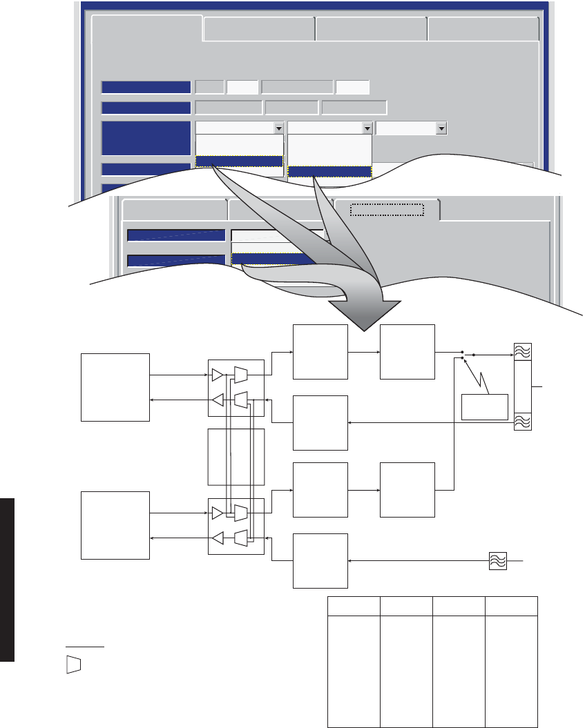
4-28
ETH PROVISIONING EXAMPLE 3: HS Tx/SD Rx/A and B Switched
MDR-8000 Eth 128 TCM150 Mbs
RADIO TYPE:
ELMC: 203R2 RADIO LINK ID: Disable
SYSTEM ID:
RADIO CONFIG:
Hot-Standby Tx Space Diversity Rx Repeater
ATPC Enabled
A&B PA Present
Option Key:
Stat/Prov/WaySide
OPTIONS:
SYSTEM ALARM:
Major/Minor
RELAYS ON/NO
TBOS Display 1 RSL Alarm Disable
BER=1x10⁻⁶
RCV SWITCHING:
Disable AGC
Radio Configuration Service Channel Eth Facilities
WaySide DS1 Facilities
Tuessday, March 7, 2000 1:27:15 PM USI Version R1.00 MDR-8000 OC3 Controller Version R1.00
No Rx
Non-Standby Rx
Hot-Standby Rx
Space Diversity Rx
Frequency Diversity Rx
No Tx
Non-Standby Tx
Hot-Standby Tx
Freq-Diversity Tx
Radio Configuration Service Channel Ethernet Facilities
Port Configuration A & B Switched
Speed Regenerator
Auto Negotiate
Allow 10 Mb Half Duplex
Allow 10 Mb Full Duplex
Allow 100 Mb Half Duplex
Allow 100 Mb Full Duplex
Allow 1000 Mb Full Duplex
Allow Input Pause
Allow Output Pause
A Only
A & B Switched
A & B Separate
A & B Summed
ALLOWABLE COMBINATIONS
ETH IN XMTR RCVR ETH OUT
RR-1
RR-1
RR-2
RR-2
RR-2
RR-2
RR-1
RR-1
ETH T-1
ETH T-1
ETH T-2
ETH T-2
ETH T-1
ETH T-1
ETH T-2
ETH T-2
ETH R-1
ETH R-1
ETH R-2
ETH R-2
ETH R-1
ETH R-1
ETH R-2
ETH R-2
RT-1
RT-2
RT-2
RT-1
RT-1
RT-2
RT-2
RT-1
ETHERNET
DEVICE
ETHERNET
DEVICE
A
TRANS-
MITTER
A
POWER
AMPLIFIER
(OPTIONAL)
MAIN
ANTENNA
PORT
RT-1
RF
RELAY
DIPLEXER
FILTER
RCV
FILTER
RR-1
A
RECEIVER
A Eth
I/O INTERFACE
ETH R-1
ETH T-1
AUXILIARY
INTERFACE
DIVERSITY
ANTENNA
PORT
B
TRANS-
MITTER
B
POWER
AMPLIFIER
(OPTIONAL)
RT-2
RR-2
B
RECEIVER
B Eth
I/O INTERFACE
ETH R-2
ETH T-2
OFF-LINE
XMTR IS
TERMINATED
LEGEND
= SWITCH
ETH R
= Ethernet RCV
ETH T = Ethernet XMT
RR = Radio RCV
RT = Radio XMT
ETH-1025
Issue 8
03/02/07
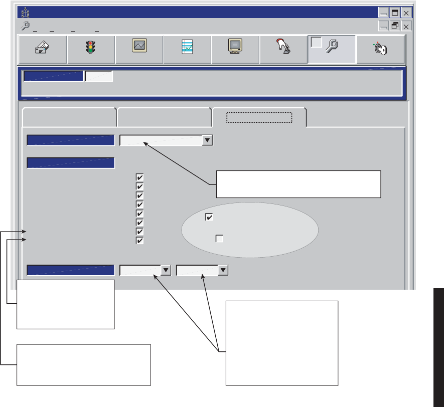
4-29
4.9 PROVISION ETHERNET FACILITY
See Figure 4 - 15 to provision the Ethernet radio.
Figure 4 - 15 Ethernet Facilities Provisioning
Radio Configuration Service Channel Ethernet Facilities
LOCAL ETHERNET PROVISIONING (RS-232)
Communicating*
ELMC Address: 201R2
Port Configuration A Only
Port Operation Regenerator
INPUT
Degrade Threshold
10 Err/100 Sec
OUTPUT
10 Err/100 Sec
Auto Negotiate
Allow 10 Mb Half Duplex
Allow 10 Mb Full Duplex
Allow 100 Mb Half Duplex
Allow 100 Mb Full Duplex
Allow 1000 Mb Full Duplex
Input/Output Flow Control
Radio Link Fault Promotion
Select A Only, A & B Switched, A & B Separated, or A
& B Summed from dropdown list. See examples 1-34.
Monday, November 01, 2004 11:19:08 AM
Universal USI Version R2.00
Ethernet Controller Version R2.00
Alcatel User Interface – [Universal USI – Provisioning ]
File View Setup Options
F6
Performance
Alarm Status
F4
Station Alarm
F7 F9
Provisioning
User Control
F8
Prov. Save
F3 F5
Analog Monitor Password
F11
Select Eth Degrade alarm threshold
from drop down list.
100 Err/10 Sec
10 Err/10 Sec
100 Err/100 Sec
10 Err/100 Sec
25 Err/250 Sec
5 Err/250 Sec
1 Err/250 Sec
When checked (enabled) this
feature promotes a link fault to
external Ethernet equipment
faster than when in the normal
operating mode.
When checked (enabled) this feature
reduces latency and latency variations by
allowing frames to be forwarded without
waiting for the entire frame to be received. MDR-1114
02/04/06
= Function enabled.
All checked (default) shown.
All = Ethernet Ports disabled.

4-30
4.9.1 Auto-Negotiation
MDR-8000E auto-negotiation is not a stand-alone function, and proper operation and use
of all available functions depends on the capabilities of the external customer equipment
that is connected to the radio. Just because an autonegotiation function is checked for pro-
visioning does not automatically mean that function is fully operable. The device on the
other end of the cable must also have the capability and be provisioned with a matching
function.
4.9.1.1 Auto-Negotiate
Auto-Negotiate details are beyond the scope of this supplement. The rule of thumb to fol-
low when unsure of what functions to check or change from factory default provisioning is
leave at default (all autonegotiation functions are checked). Full autonegotiation capability
is becoming standard for manufacturers of Ethernet devices.
4.9.1.2 Allow 10, 100, and/or 1000 Mb Half and Full Duplex
If in doubt as to the link speed and mode of the external device connecting Ethernet to the
radio, check all boxes for speeds and modes. If you know the external Ethernet device has
speed and/or mode limitations, check only the boxes that apply.
Auto-Negotiate is automatically enabled when Allow 1000 Mb Full Duplex is enabled.
Auto-Negotiate must be enabled (checked) when more than one link speed is selected.
4.9.1.3 Input/Output Flow Control Features
Checking the box next to Input/Output Flow Control enables input and output pause func-
tions and the forward errored or large frame function. These flow control functions are
described in the following paragraphs.
4.9.1.3.1 Input Pause Feature
See Figure 4 - 16. This feature makes the auto-negotiation function willing to stop receiving
traffic. When the radio input buffers approach overflow, the function sends a pause mes-
sage to the link partner that is transmitting data to the radio, telling the device to tempo-
rarily stop sending data. The link partner will stop sending data if the device has and is
provisioned with the Allow Option Pause function.
If the link partner is either not equipped with or is not provisioned for input pause, data
overflowing the registers in the radio will be lost, regardless of the provisioning for input
pause in the radio. Any time there is an overflow, the radio will alarm and indicate
Dropped Frames on the Performance Monitor screens.
4.9.1.3.2 Pause Feature
This feature auto-negotiation function willing to stop sending traffic. When the input buff-
ers on the link partner approach overflow, the link partner sends a pause message to the
radio telling the radio to temporarily stop sending data. If the Input/Output Flow Control
function is checked, the radio will stop sending out data.
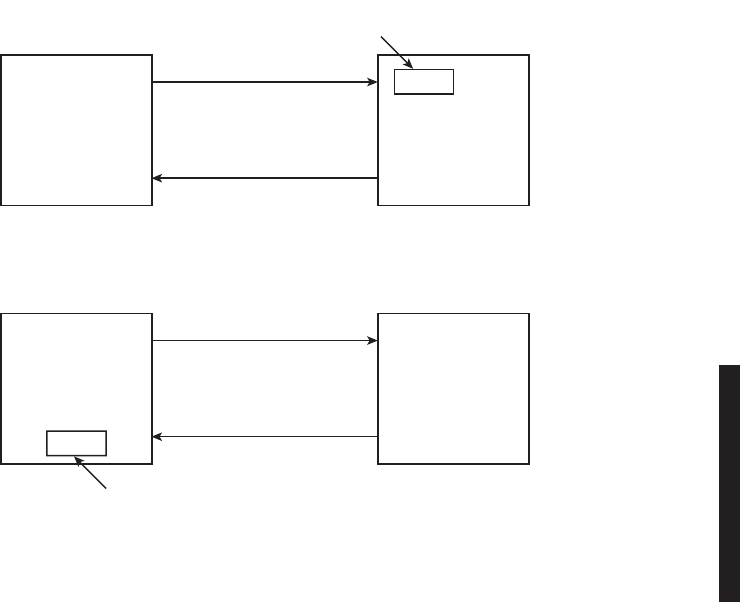
4-31
4.9.1.4 Input Pause Feature
See Figure 4 - 16. Checking the box next to Allow Input Pause makes the auto-negotiation
function willing to stop receiving traffic. When the radio input buffers approach overflow,
the function sends a pause message to the ink partner that is transmitting data to the
radio, telling the device to temporarily stop sending data. The link partner will stop send-
ing data if the device has and is provisioned with the Allow Option Pause function.
If the link partner is either not equipped with or is not provisioned for input pause, data
overflowing the registers in the radio will be lost, regardless of the provisioning for input
pause in the radio. Any time there is an overflow, the radio will alarm and indicate
Dropped Frames on the Performance Monitor screens.
Figure 4 - 16 Input/Output Pause Messaging
MDR-8000E
Ethernet
Radio
Link
Partner
Buffer
Buffer
Near Full
Data Flow
MDR-1113
02/14/04
Pause Msg
TX
RX
Allow RX Pause Message
MDR-8000E
Ethernet
Radio
Link
Partner
Buffer
Buffer
Near Full
Pause Msg
Data Flow
TX
RX
Allow RX Pause Message
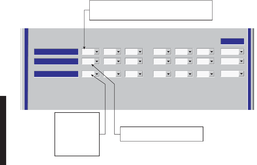
4-32
4.9.1.5 Allow Output Pause
Checking the box next to Allow Output Pause makes the radio auto-negotiation function
willing to stop sending traffic. When the input buffers on the link partner approach over-
flow, the link partner sends a pause message to the radio, telling the radio to temporarily
stop sending data. If the Allow Output Pause function is checked, the radio will stop send-
ing out data.
4.10 PROVISION DS1 FACILITY
See Figure 4 - 17 to provision the DS1 lines (if equipped).
Figure 4 - 17 Ethernet Radio DS1 Facilities Provisioning
Select All
123 123
DS1 LINES
FRAME FORMAT
FRAME FORMAT
ESF
LINE CODING
LINE CODING
B8ZS
LINE LENGTH
LINE LENGTH
0-133
ESF
B8ZS
0-1
ESF
B8ZS
0-133
ESF
B8ZS
0-133
ESF
B8ZS
0-133
ESF
B8ZSB8ZS
ESF
0-1330-133
Eth-1035
08/15/05
Select distance in ft.
to crossconnect:
0-133
133-266
266-399
399-533
533-655
Select AMI or B8ZS coding for Wayside
DS1 line to match coding on DS1 input.
Select Super Frame (SF) or Extended Super Frame (ESF)
framing format, Clear Channel (no frame format), or Disable.
Select Disable to disable alarm reporting for DS1 line.
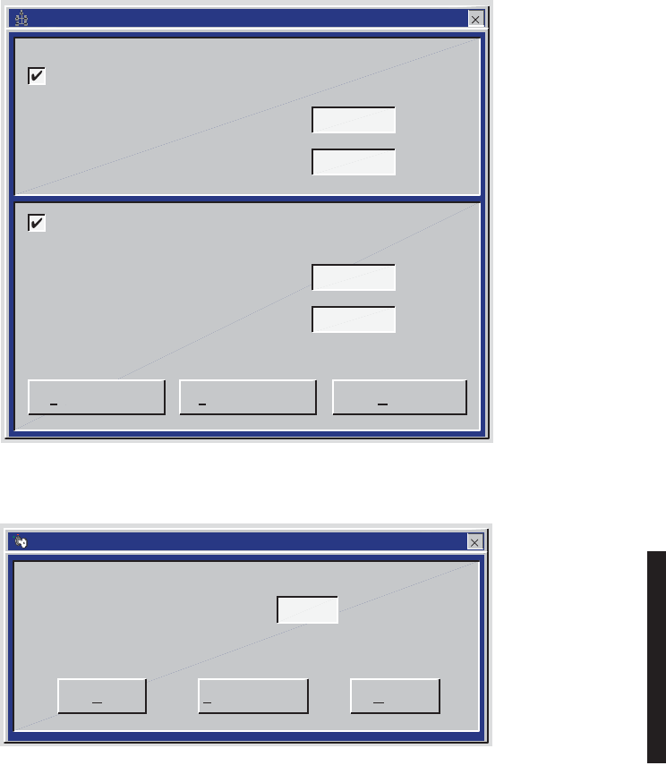
4-33
Figure 4 - 18 Password Screens
MDR-1032
09/02/04
OK Cancel
Forgot Password
Please Enter Level 1 Password:
Level One Password --
MDR-1033
09/02/04
Cancel
Forgot PasswordSave Password
Enter the New Level 1 Password:
Confirm the New Level 1 Password:
Change Level 1 Password
Enter the New Level 2 Password:
Confirm the New Level 2 Password:
Change Level 2 Password
Change Password --
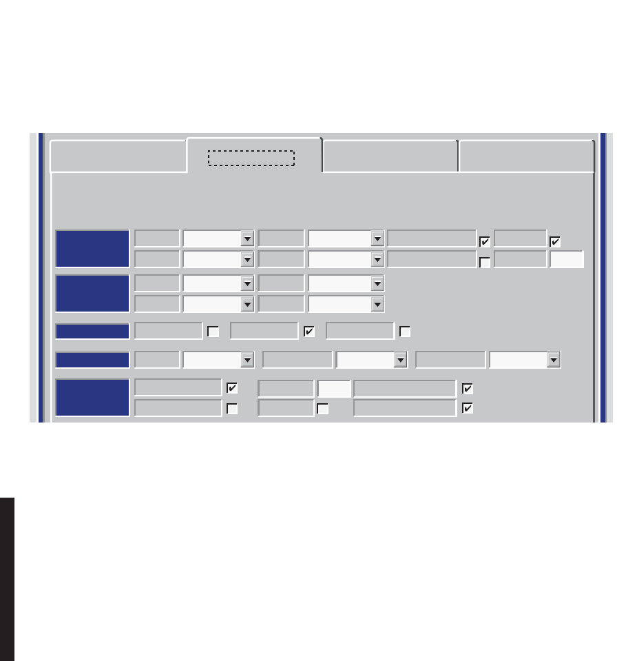
4-34
Figure 4 - 19 Service Channel Provisioning
AUDIO 1
AUDIO 2
RS-232
MCS
TMN
Channel
3
MCS Transport
RF/Rptr
PPP Transport
RF/Rptr
Channel E-Lead
Off -GND
Level M-Lead
0/0 Norm
Address
A12A
J308/J309 Input Clocks
RSS
J310 Modem J308/J309 TerminationRDS/RAS/RCD
Channel 1 Channel 2 Repeater D/1
Channel E-Lead All Call Detect
1 -GND
DTMF
Level M-Lead 2-Wire Auto Squelch
0/0 Norm 00
Address
Radio Configuration Service Channel WaySide DS1 Facilities
DS3 Facilities
Alcatel User Interface – [System, DS3, and DS1 Provisioning -- MDR-8000 DS3]
File View Setup Options
F6
Performance
Alarm Status
F4
Analog Monitor Station Alarm
F7
Provisioning
F9
User Control
F8F5
Prov. Save
F3
Thursday, March 7, 2000 1:27:15 PM USI Version R1.03 Controller Version R1.03 MDR-8000 3-DS3
ELMC Address:
ELMC Description:
J7914
DURANGO
LOCAL DS3 PROVISIONING
Communicating***
MDR-1034
09/16/04
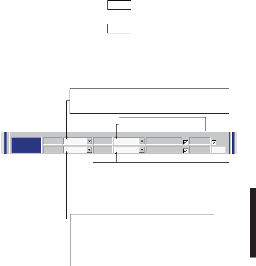
4-35
Figure 4 - 20 Audio 1 Provisioning (Sheet 1 of 2)
AUDIO 1:
AUDIO 2:
RS-232
MCS
TMN
Channel
3
MCS Transport
RF/Rptr
PPP Transport
RF/Rptr
Channel E-Lead
Off -GND
Level M-Lead
0/0 Norm
Address
A12A
J308/J309 Input Clocks
RSS
J310 Modem J308/J309 TerminationRDS/RAS/RCD
Channel 1 Channel 2 Repeater D/1
Channel E-Lead All Call Detect
Off -GND
DTMF
Level M-Lead 2-Wire Auto Squelch
0/0 Norm 00
Address
Radio Configuration Service Channel WaySide DS1 Facilities
DS3 Facilities
Alcatel User Interface – [System, DS3, and DS1 Provisioning -- MDR-8000 DS3]
File View Setup Options
F6
Performance
Alarm Status
F4
Analog Monitor Station Alarm
F7
Provisioning
F9
User Control
F8F5
Prov. Save
F3
Thursday, March 7, 2000 1:27:15 PM USI Version R1.03 Controller Version R1.03 MDR-8000 3-DS3
ELMC Address:
ELMC Description:
J7914
DURANGO
LOCAL DS3 PROVISIONING
Communicating***
Audio provisioning is required only if 4-wire audio equipment (external equipment not part of
the radio) is supplied and the external audio equipment is connected to audio port 1 J316 or
audio port 2 J317 on the radio backplane. These provisionable 4-wire audio functions should
not be confused with the 2-wire audio handset. The handset is fully operational after it is
connected to the TEL jack on the radio controller module, provided the radio is provisioned
Audio 1.
The most common audio provisioning is: 1:, 2:, or 3: AUDIO 1 0/0 Norm.
Note
The 2-wire handset is transported over Audio 1 only.
Note
0/0 – RADIO REQUIRES 0 dBm AUDIO INPUT SIGNAL AT CONNECTOR J316.
THE RECEIVED AUDIO SIGNALS ARE NOT AMPLIFIED. THE RADIO
OUTPUTS 0 dBm ON AUDIO 1 CONNECTOR J316. THIS SELECTION IS
NORMALLY SUFFICIENT IF THE RADIO AND EXTERNAL AUDIO
EQUIPMENT ARE LOCATED IN THE SAME SHELTER, ROOM AND EVEN
BUILDING. LONGER DISTANCES (SUCH AS BETWEEN BUILDINGS) MAY
REQUIRE AMPLIFICATION ON THE OUTPUT SIGNAL. IN THIS CASE,
SELECT -16/+7 WHERE THE RADIO INPUT REQUIRED IS -16 dBm AND THE
RADIO AMPLIFIES RECEIVED AUDIO SIGNALS TO PROVIDE A +7 dBm
OUTPUT AT AUDIO 1 CONNECTOR J316.
1:, 2: OR 3: – THE 64 kb/s SERVICE CHANNEL TO BE INSERTED INTO RADIO
OVERHEAD IS 1. IF SERVICE CHANNEL 1 IS ALREADY IN USE, SELECT SERVICE
CHANNEL 2 (2:) OR SERVICE CHANNEL 3 (3:) FOR THE AUDIO CHANNEL. WHATEVER
IS SELECTED FOR SERVICE CHANNEL 1, 2, OR 3, IT MUST BE THE SAME END-TO-END.
SELECT
E-Lead-24Vdc
OR
E-Lead GND
TO
BE APPLIED TO SERVICE CHANNEL E-LEAD.
NORM – MODE OF OPERATION SELECTED IS NORMAL. IN THIS MODE
THE RADIO REQUIRES AN OFF HOOK SIGNAL FROM THE EXTERNAL
AUDIO EQUIPMENT. THIS MEANS THAT THE AUDIO EQUIPMENT USED
TO CONNECT TO THE RADIO MUST HAVE E AND M-LEAD SIGNALING
CAPABILITY (MOST AUDIO EQUIPMENT DOES HAVE THIS CAPABILITY).
IF THE EXTERNAL AUDIO EQUIPMENT DOES NOT HAVE E AND
M-LEAD SIGNALING CAPABILITY, SELECT O/H AND A CONSTANT
OFF-HOOK SIGNAL WILL BE PROVIDED AUTOMATICALLY BY THE
RADIO CONTROLLER SOFTWARE.
MDR-1035A
09/06/04
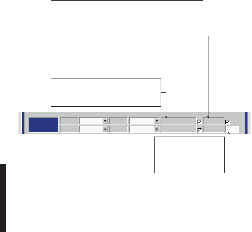
4-36
Figure 4 - 20 Audio 1 Provisioning (Sheet 2 of 2)
AUDIO 1:
AUDIO 2:
RS-232
MCS
TMN
Channel
3
MCS Transport
RF/Rptr
PPP Transport
RF/Rptr
Channel E-Lead
Off -GND
Level M-Lead
0/0 Norm
Address
A12A
J308/J309 Input Clocks
RSS
J310 Modem J308/J309 TerminationRDS/RAS/RCD
Channel 1 Channel 2 Repeater D/1
Channel E-Lead All Call Detect
Off -GND
DTMF
Level M-Lead 2-Wire Auto Squelch
0/0 Norm 00
Address
Radio Configuration Service Channel WaySide DS1 Facilities
DS3 Facilities
Alcatel User Interface – [System, DS3, and DS1 Provisioning -- MDR-8000 DS3]
File View Setup Options
F6
Performance
Alarm Status
F4
Analog Monitor Station Alarm
F7
Provisioning
F9
User Control
F8F5
Prov. Save
F3
Thursday, March 7, 2000 1:27:15 PM USI Version R1.03 Controller Version R1.03 MDR-8000 3-DS3
ELMC Address:
ELMC Description:
J7914
DURANGO
LOCAL DS3 PROVISIONING
Communicating***
DOUBLE CLICK TO ENABLE
(000 DISPLAYS). ENTER 3-DIGIT
STATION CALL NUMBER. OPERATOR
CAN DIAL THIS NUMBER AND RING/
COMMUNICATE WITH THE STATION
VIA ORDERWIRE. SELECT OFF TO
DISABLE DTMF.
WHEN All Call Detect IS SELECTED, ALL TELEPHONES
RING WHEN CALL IS INITIATED. WHEN All Call Detect IS
NOT SELECTED, TELEPHONE ASSOCIATED WITH RADIO
WILL NOT RING. USEFUL IN SITUATIONS WHERE MULTIPLE
RADIOS ARE CONNECTED AT ONE SITE.
MDR-1035B
09/16/04
DTMF ALLOWS YOU TO DIALUP AND RING OTHER SITES USING THE 2-WIRE
HANDSET. ONLY THE RINGING IS DETECTED. COMMUNICATION OVER THE
HANDSET IS PARTY-LINE. DTMF ADDRESSING IS A LOCAL FUNCTION NOT A
NETWORK FUNCTION, THEREFORE, IF ONE OR MORE RADIOS ARE ASSIGNED
THE SAME DTMF ADDRESS, THEY WILL ALL RING WHEN THAT ADDRESS IS
DIALED.
TO BE ABLE TO USE THE DTMF FUNCTION:
1. AUDIO 1 MUST BE SELECTED FOR 2-WIRE HANDSET OPERATION.
2. DTMF MUST BE TURNED ON (CHECKED) ON THE AUDIO PROVISIONING
SCREEN.
3. 2-WIRE HANDSET MUST BE CONNECTED TO TEL JACK ON CONTROLLER
MODULE.
4. RADIOS MUST BE PROVISIONED WITH DTMF ADDRESS.
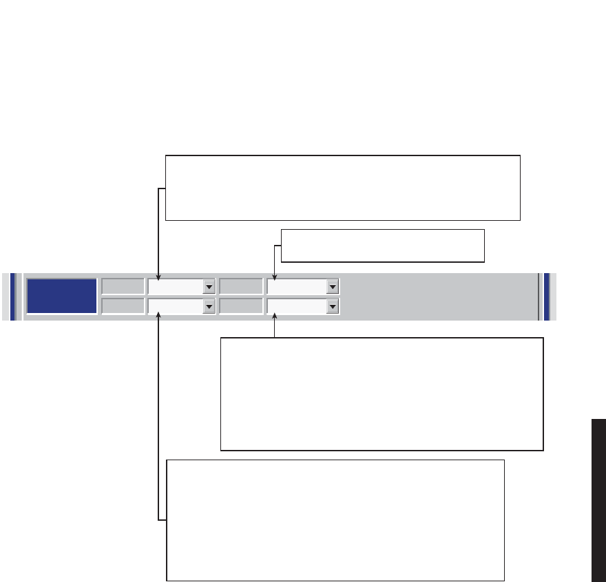
4-37
Figure 4 - 21 Audio 2 Provisioning
AUDIO 1:
AUDIO 2:
RS-232
MCS
TMN
Channel
3
MCS Transport
RF/Rptr
PPP Transport
RF/Rptr
Channel E-Lead
Off -GND
Level M-Lead
0/0 Norm
Address
A12A
J308/J309 Input Clocks
RSS
J310 Modem J308/J309 TerminationRDS/RAS/RCD
Channel 1 Channel 2 Repeater D/1
Channel E-Lead All Call Detect
Off -GND
DTMF
Level M-Lead 2-Wire Auto Squelch
0/0 Norm 00
Address
Radio Configuration Service Channel WaySide DS1 Facilities
DS3 Facilities
Alcatel User Interface – [System, DS3, and DS1 Provisioning -- MDR-8000 DS3]
File View Setup Options
F6
Performance
Alarm Status
F4
Analog Monitor Station Alarm
F7
Provisioning
F9
User Control
F8F5
Prov. Save
F3
Thursday, March 7, 2000 1:27:15 PM USI Version R1.03 Controller Version R1.03 MDR-8000 3-DS3
ELMC Address:
ELMC Description:
J7914
DURANGO
LOCAL DS3 PROVISIONING
Communicating***
MDR-1036A
09/06/04
0/0 – RADIO REQUIRES 0 dBm AUDIO INPUT SIGNAL AT CONNECTOR J317.
THE RECEIVED AUDIO SIGNALS ARE NOT AMPLIFIED. THE RADIO
OUTPUTS 0 dBm ON AUDIO 2 CONNECTOR J317. THIS SELECTION IS
NORMALLY SUFFICIENT IF THE RADIO AND EXTERNAL AUDIO EQUIPMENT
ARE LOCATED IN THE SAME SHELTER, ROOM AND EVEN BUILDING.
LONGER DISTANCES (SUCH AS BETWEEN BUILDINGS) MAY REQUIRE
AMPLIFICATION ON THE OUTPUT SIGNAL. IN THIS CASE, SELECT -16/+7
WHERE THE RADIO INPUT REQUIRED IS -16 dBm AND THE RADIO
AMPLIFIES RECEIVED AUDIO SIGNALS TO PROVIDE A +7 dBm OUTPUT AT
AUDIO 2 CONNECTOR J317.
1:, 2: OR 3: – THE 64 kb/s SERVICE CHANNEL TO BE INSERTED INTO RADIO
OVERHEAD IS 1, 2, or 3. IF SERVICE CHANNEL 1 IS ALREADY IN USE, SELECT
SERVICE
CHANNEL 2 (2:) OR SERVICE CHANNEL 3 (3:) FOR THE AUDIO CHANNEL.
WHATEVER IS SELECTED FOR SERVICE CHANNEL 1, 2, OR 3, IT MUST BE THE
SAME END-TO-END.
SELECT
E-Lead-24Vdc
OR
E-Lead GND
TO
BE APPLIED TO SERVICE CHANNEL E-LEAD.
NORM – MODE OF OPERATION SELECTED IS NORMAL. IN THIS MODE
THE RADIO REQUIRES AN OFF HOOK SIGNAL FROM THE EXTERNAL
AUDIO EQUIPMENT. THIS MEANS THAT THE AUDIO EQUIPMENT USED
TO CONNECT TO THE RADIO MUST HAVE E AND M-LEAD SIGNALING
CAPABILITY (MOST AUDIO EQUIPMENT DOES HAVE THIS CAPABILITY).
IF THE EXTERNAL AUDIO EQUIPMENT DOES NOT HAVE E AND
M-LEAD SIGNALING CAPABILITY, SELECT O/H AND A CONSTANT
OFF-HOOK SIGNAL WILL BE PROVIDED AUTOMATICALLY BY THE
RADIO CONTROLLER SOFTWARE.
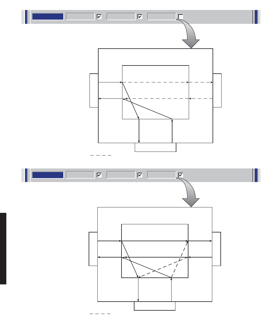
4-38
Figure 4 - 22 RS-232 Provisioning
RS-232
Channel 1 Channel 2 Repeater D/1
RS-232
Channel 1 Channel 2 Repeater D/1
MDR-1037
09/16/04
J312
J343 J314
RCV SC
DATA E
XMT SC
DATA W
INSERT
W
AE-37( ) CONTROLLER
SELECT FOR TERMINAL
(ONE DIRECTION)
TO/FROM
A
I/O INTFC
RS-232 RXD1
DATA PATH NOT USED
RS-232 TXD1
DROP
E
SC MULDEM
J312
J343 J314
THRU
THRU
RCV SC
DATA E
XMT SC
DATA W
DROP
EINSERT
E
INSERT
WDROP
W
AE-37( ) CONTROLLER
SC MULDEM
SELECT FOR REPEATER
(TWO DIRECTIONS)
TO/FROM
A
I/O INTFC
RS-232 RXD1
BRIDGED PATHS
RS-232 TXD1
XMT SC
DATA E
RCV SC
DATA W
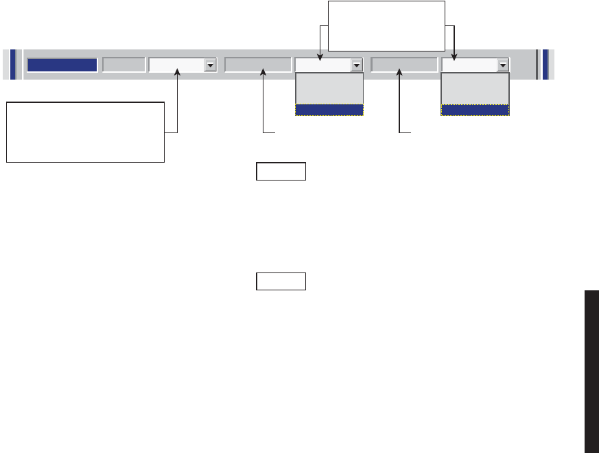
4-39
Figure 4 - 23 MCS/TMN Transport Provisioning (Sheet 1 of 5)
TMN
Channel
3
MCS Transport
RF/Rptr
PPP Transport
RF/Rptr
MDR-1056
04/03/07
Note
For
MCS-11
to operate properly, all radio controllers in a system inter- connected by
RF
or RPTR must have the same
PPP
transport provisioning on facing (interconnecting)
interfaces. The valid transport combinations (for terminal or repeater) are shown. The
combination chosen from MCS TRANSPORT and
PPP TRANSPORT
determines the
RPTR PORT
and
RF PORT PROTOCOLS
supported.
Note
MCS-11 must be enabled even if it is unused and TMN (only)
is used for alarm monitoring and controls. For specific TMN
Initial Turnup requirements, refer to CD.
MCS-11 data MCS-11 and
IP data
Select ports on I/O INTFC
module that will be used
to insert and drop service
channel data.
Select channel 1, 2, or 3 as
service channel to be used for
MCS
transport and/or
PPP
transport.
Select
OFF
to disable
MCS
and
PPP
transport.
None
RF
Rptr
RF/Rptr
None
RF
Rptr
RF/Rptr

4-40
Figure 4 - 23 MCS/TMN Transport Provisioning (Sheet 2 of 5)
MDR-8000
A
MDR-8000
B
MDR-8000
C
MDR-8000
D
RPTR PORT
RF PORT
MCS TRANSPORT
NONE
PPP TRANSPORT
NONE
RPTR PORT
RF PORT
MCS TRANSPORT
RF
PPP TRANSPORT
NONE
RPTR PORT
RF PORT
MCS TRANSPORT
RPTR
PPP TRANSPORT
NONE
RPTR PORT
RF PORT
MCS TRANSPORT
RF / RPTR
PPP TRANSPORT
NONE
ANY
PROTOCOL MCS-11
DISABLED MCS-11
ANY PROTOCOL DISABLED
MCS-11 MCS-11
MDR-1255
12/05/06
Notes:
1) Set PPP Transport to NONE if the repeater and RF ports interface with radios not TMN
compatible.
2) RF at both ends of the hop must be provisioned for the same PPP Transport selection.
3) RPTR at both ends must be provisioned for the same PPP Transport selection.
4) MCS-11 = Non TMN compatible
MCS-11 + PPP = TMN compatible
5) TMN compatibility is determined by the radio controller software and radio provisioning.
DRAWING
REFERENCE RADIO PORTRADIO TRANSPORT SETTING
A
B
C
D
MCS
NONE
RF
RPTR
RF/RPTR
PPP
NONE
NONE
NONE
NONE
RF
PASS-THROUGH MODE.
NO LOCAL INSERT CAPABILITY.
MCS-11
DISABLED
MCS-11
RPTR
DISABLED
MCS-11
MCS-11
PPP TRANSPORT SETTING = NONE
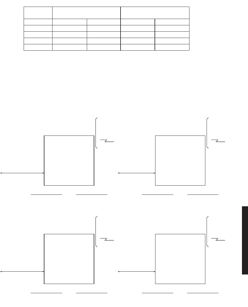
4-41
Figure 4 - 23 MCS/TMN Transport Provisioning (Sheet 3 of 5)
MDR-8000
A
MDR-8000
B
MDR-8000
C
MDR-8000
D
RPTR PORT
MCS-11
PPP
RF PORT
MCS TRANSPORT
NONE
PPP TRANSPORT
RF
RPTR PORT
MCS-11
PPP
RF PORT
MCS TRANSPORT
RF
PPP TRANSPORT
RF
RPTR PORT
MCS-11
PPP
RF PORT
MCS TRANSPORT
RPTR
PPP TRANSPORT
RF
RPTR PORT
MCS-11
PPP
RF PORT
MCS TRANSPORT
RF / RPTR
PPP TRANSPORT
RF
DISABLED DISABLED
MCS-11 MCS-11
Notes:
1)
Set PPP Transport to RF when the farend radio is TMN compatible, but the radio connected via the
repeater cable is not.
2) RF at both ends of the hop must be provisioned for the same PPP Transport selection.
3) RPTR at both ends must be provisioned for the same PPP Transport selection.
4) MCS-11 = Non TMN compatible
MCS-11 + PPP = TMN compatible
5) TMN compatibility is determined by the radio controller software and radio provisioning.
DRAWING
REFERENCE RADIO PORTRADIO TRANSPORT SETTING
A
B
C
D
MCS
NONE
RF
RPTR
RF/RPTR
PPP
RF
RF
RF
RF
RF
MCS-11 + PPP
MCS-11 + PPP
MCS-11 + PPP
MCS-11 + PPP
RPTR
DISABLED
DISABLED
MCS-11
MCS-11
PPP TRANSPORT SETTING = RF
MDR-1254
12/05/06
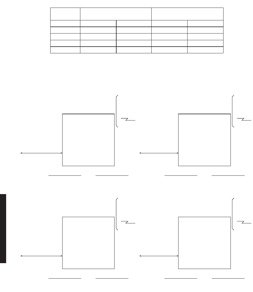
4-42
Figure 4 - 23 MCS/TMN Transport Provisioning (Sheet 4 of 5)
MDR-8000
A
MDR-8000
B
MDR-8000
C
MDR-8000
D
MCS-11
PPP
RPTR PORT
MCS TRANSPORT
NONE
PPP TRANSPORT
RPTR
MCS-11
PPP
RPTR PORT
MCS TRANSPORT
RF
PPP TRANSPORT
RPTR
MCS-11
PPP
RPTR PORT
MCS TRANSPORT
RPTR
PPP TRANSPORT
RPTR
MCS-11
PPP
RPTR PORT
MCS TRANSPORT
RF / RPTR
PPP TRANSPORT
RPTR
DISABLED MCS-11
DISABLED MCS-11
RF PORT RF PORT
RF PORT RF PORT
Notes:
1) RF at both ends of the hop must be provisioned for the same PPP Transport selection.
2) RPTR at both ends must be provisioned for the same PPP Transport selection.
3) MCS-11 = Non TMN compatible
MCS-11 + PPP = TMN compatible
4) TMN compatibility is determined by the radio controller software and radio provisioning.
DRAWING
REFERENCE RADIO PORTRADIO TRANSPORT SETTING
A
B
C
D
MCS
NONE
RF
RPTR
RF/RPTR
PPP
RPTR
RPTR
RPTR
RPTR
RF
DISABLED
MCS-11
DISABLED
MCS-11
RPTR
MCS-11 + PPP
MCS-11 + PPP
MCS-11 + PPP
MCS-11 + PPP
PPP TRANSPORT SETTING = RPTR
MDR-1253
12/05/06
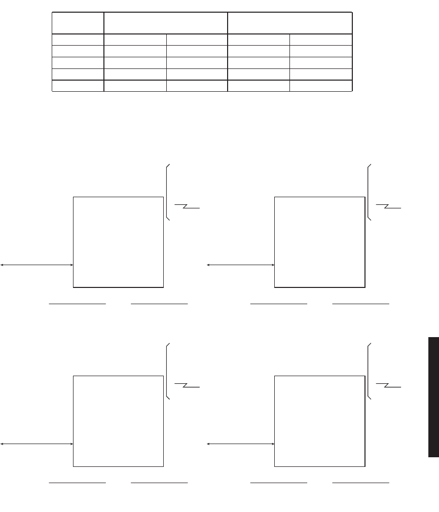
4-43
Figure 4 - 23 MCS/TMN Transport Provisioning (Sheet 5 of 5)
MDR-8000
A
MDR-8000
B
MDR-8000
C
MDR-8000
D
MCS-11
PPP
RPTR PORT
MCS-11
PPP
MCS TRANSPORT
NONE
PPP TRANSPORT
RF / RPTR
MCS-11
PPP
RPTR PORT
MCS-11
PPP
MCS TRANSPORT
RF
PPP TRANSPORT
RF / RPTR
MCS-11
PPP
RPTR PORT
MCS-11
PPP
MCS TRANSPORT
RPTR
PPP TRANSPORT
RF / RPTR
MCS-11
PPP
RPTR PORT
MCS-11
PPP
MCS TRANSPORT
RF / RPTR
PPP TRANSPORT
RF / RPTR
RF PORT RF PORT
RF PORT RF PORT
Notes:
1) RF at both ends of the hop must be provisioned for the same PPP Transport selection.
2) RPTR at both ends must be provisioned for the same PPP Transport selection.
3) MCS-11 = Non TMN compatible
MCS-11 + PPP = TMN compatible
4) TMN compatibility is determined by the radio controller software and radio provisioning.
DRAWING
REFERENCE RADIO PORTRADIO TRANSPORT SETTING
A
B
C
D
MCS
NONE
RF
RPTR
RF/RPTR
PPP
RF/RPTR
RF/RPTR
RF/RPTR
RF/RPTR
RF
MCS-11 + PPP
MCS-11 + PPP
MCS-11 + PPP
MCS-11 + PPP
RPTR
MCS-11 + PPP
MCS-11 + PPP
MCS-11 + PPP
MCS-11 + PPP
PPP TRANSPORT SETTING = RF/RPTR
MDR-1252
12/05/06

4-44
Figure 4 - 24 MCS-11 Provisioning
AUDIO 1:
AUDIO 2:
RS-232
MCS
TMN
Channel
3
MCS Transport
RF/Rptr
PPP Transport
RF/Rptr
Channel E-Lead
Off -GND
Level M-Lead
0/0 Norm
Address
A12A
J308/J309 Input Clocks
RSS
J310 Modem J308/J309 TerminationRDS/RAS/RCD
Channel 1 Channel 2 Repeater D/1
Channel E-Lead All Call Detect
Off -GND
DTMF
Level M-Lead 2-Wire Auto Squelch
0/0 Norm 00
Address
Radio Configuration Service Channel WaySide DS1 Facilities
DS3 Facilities
Alcatel User Interface – [System, DS3, and DS1 Provisioning -- MDR-8000 DS3]
File View Setup Options
F6
Performance
Alarm Status
F4
Analog Monitor Station Alarm
F7
Provisioning
F9
User Control
F8F5
Prov. Save
F3
Thursday, March 7, 2000 1:27:15 PM USI Version R1.03 Controller Version R1.03 MDR-8000 3-DS3
ELMC Address:
ELMC Description:
J7914
DURANGO
LOCAL DS3 PROVISIONING
Communicating***
Allows user to enter the NE MCS address. The following list
provides a valid address for each station:
ALPHA NUMERIC ALPHA
A 1 A
through through through
H 16 F
MDR-1039
06/23/05
Note
A default MCS-11 address
(A1A)
is assigned automatically.
A different unique address must be entered for each radio
to prevent concurrent responses to poll from more than one
radio with the same address. If multiple responses are
received, the response data is invalid.
Check RDS/RAS/RCD to allow
controller to respond when Remote
Detail Scanner (RDS), Remote
Analog Scanner (RAS), or Remote
Control Decoder (RCD) is polled. If
this operation is not checked,
controller does not respond when
RDS, RAS, or RCD is polled.
Check RSS to allow Controller to
respond when Remote Station
Scanner (RSS) is polled. If this option
is not checked, Controller does not
respond when RSS is polled.
Un-check J310 Modem to enable XMT, RCV,
and Output Clocks. Check J310 Modem to
disable XMT and RCV Clocks. All clocks to
be provided by external modem.
Check MCS-11 J309 Termination to enable
resistive termination at the end of an MCS-11
"daisy chain". Un-check J310 Termination for
stand-alone applications or when MDR-8000
is just a link in a daisy chain.
Check J308/J309 Input clocks if radio
syncs off XMT and RCV clocks supplied by
external source (such as another radio).
Un-check
J308/J309 Input clocks
if radio is
providing XMT and RCV clocks for other
radios to sync on.
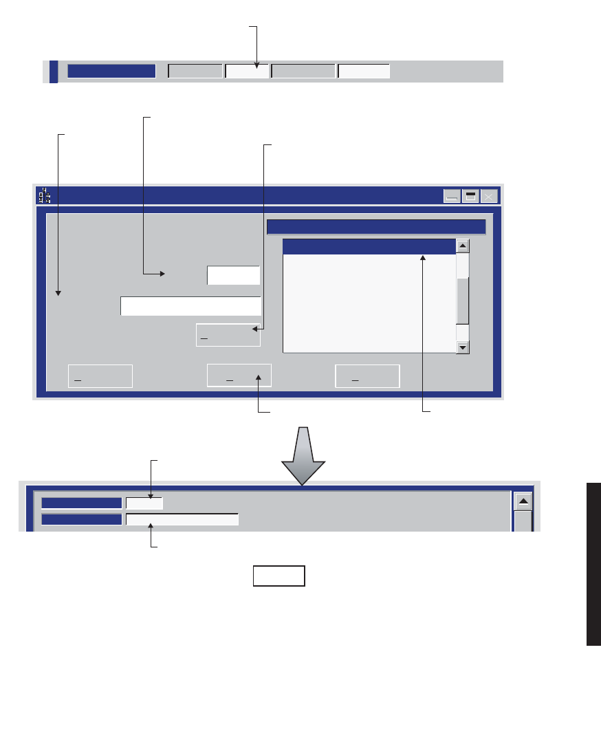
4-45
Figure 4 - 25 ELMC Provisioning
Setup ELMC Address -- MDR-8000
Extended Link Monitor Channel (Elmc) Address
J7914
DURANGO
Description:
ELMC:
Save Cancel
Delete Elmc
Add Elmc=>
J7914 -- DURANGO
5. TYPE IN 5-CHARACTER
ADDRESS. MUST MATCH
ADDRESS IN STEP 1
EXACTLY.
6. TYPE IN
DESCRIPTION
(IF DESIRED).
7. CLICK HERE
TO ENTER NEW
ADDRESS AND
DESCRIPTION
8. CLICK HERE
TO SAVE.
PROVISION ANY ONE OR ALL RADIOS AT A SITE, LOCALLY, USING FOLLOWING PROCEDURE:
LOCAL PROVISIONING
Communicating
ELMC Address:
Description:
DURANGO
J7914
2. BACKSPACE TO DELETE
CURRENT ELMC ADDRESS
(IF ANY).
3. ENTER 5-CHARACTER
ELMC ADDRESS.
4. OPEN ELMC ADDRESS
SETUP SCREEN.
LMW-1019
08/08/02
SYSTEM ID:
ELMC
J7914
RADIO LINK ID: Disable
1. SINGLE CLICK TO
PLACE CURSOR
HERE.
DISPLAYS
ENTERED ADDRESS
DISPLAYS ENTERED
DESCRIPTION (IF ANY)
DISPLAYS
ENTERED ADDRESS
Note
Each network element controller with ELMC must first be locally provisioned with a unique ELMC
or remote address. The ELMC address is not related to MCS-11. Any name can be entered as long as
the name is a 5-character, alphanumeric word. The address is case sensitive. Space, dash, slash,
asterisk, and underscored characters are not allowed. If small numbers are used as addresses, then it
is necessary to fill higher order digits with zeros. For example, if the address is the value 1, then the
address must be entered as 00001. No address, or the same address used on multiple network
elements, prevents ELMC access to that/those network elements. The remote address can only be
pro-visioned and changed locally. Service-affecting functions, including operation mode, radio
configuration, and remote address, cannot be provisioned or changed remotely.
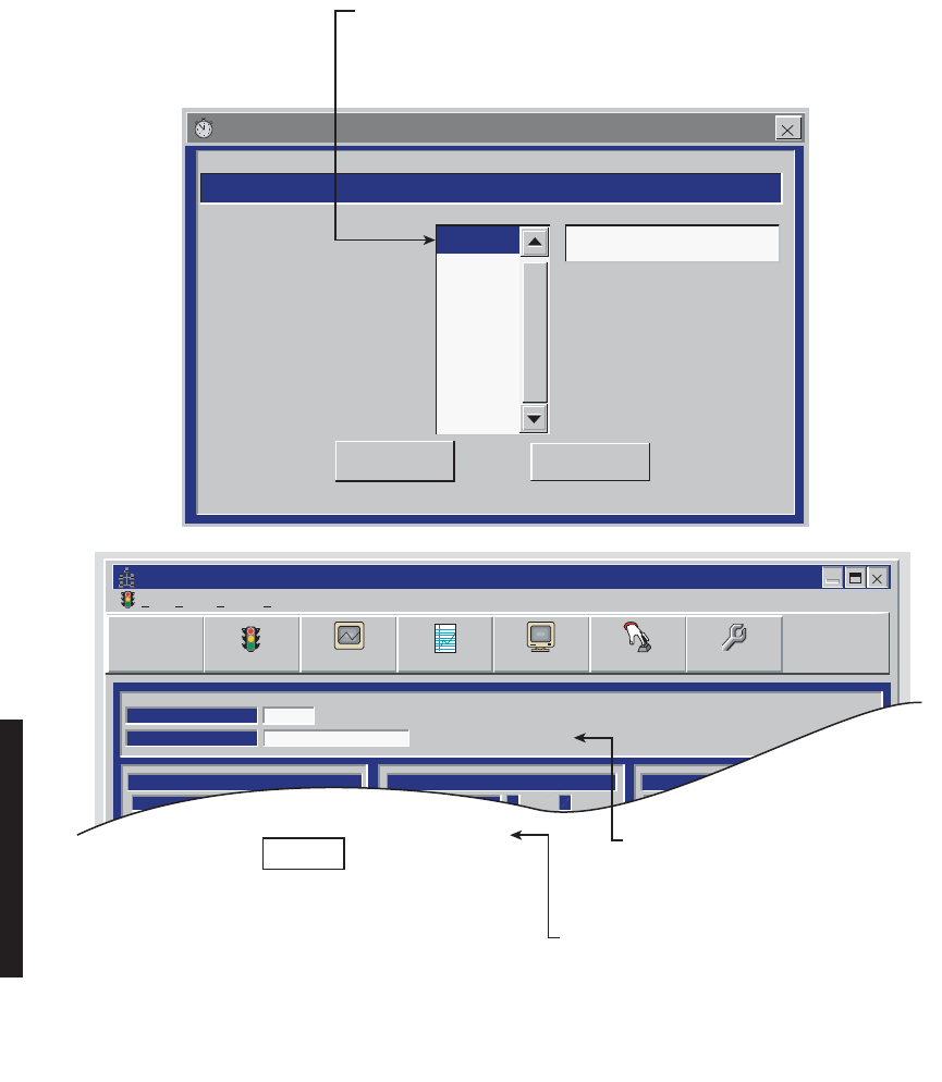
4-46
Figure 4 - 26 ELMC Remote Time-Out Constant Provisioning
Remote Time-Out Constants -- MDR-8000
Select a value in the following list to change the current remote timeout
OK Cancel
3 secs
4 secs
5 secs
6 secs
7 secs
8 secs
9 secs
10 secs
Current time-out is 3 secs
Alcatel User Interface - [Alarm Status -- MDR-8000 OC3]
File View Setup Options
REMOTE STATUS ALARM
Retrieving Provisioning
ELMC Address [F8]:
ELMC Description:
DURANGO
J7914
A B
TRANSMIT
TRANSMITTER
STATUS
A B
RECEIVER
A B
COMMON
RECEIVER
STATUS
I/O
PWR
STATUS
F6
Performance
Alarm Status Analog Monitor
F5
Station Alarm
F7
Provisioning
F9
Acknowledge
F3
User Control
F8
✓
F4
LMW-4024A
08/08/02
SELECT TIME LOCALLY FOR ELMC RESPONSE TO A REQUEST
FOR STATUS BEFORE TRYING AGAIN. SELECT SHORTER TIME
(5 SECS) FOR SHORTER SYSTEMS (10 HOPS OR LESS).
SELECT LONGER TIME (10 SECS) FOR SYSTEMS WITH 10 HOPS
OR MORE.
MESSAGE DISPLAYED FOR LENGTH
OF TIME SELECTED DURING TIME LOCAL
RADIO IS ATTEMPTING TO COMMUNICATE
WITH REMOTE ADDRESS VIA ELMC.
MESSAGE DISPLAYED FOR LENGTH
OF TIME SELECTED IF THERE IS NO
RESPONSE TO REQUEST FOR STATUS/
CONTROL/PROVISIONING.
No Report
Note
If the time-out value selected is too short, there
may not be enough time for the remote
controller to respond before the requesting
controller times out, resulting in a constant No
Report. ELMC response time delay is a function
of controller circuitry and is not linear. Always
start with longer time-out, then reduce time to
an acceptable value.
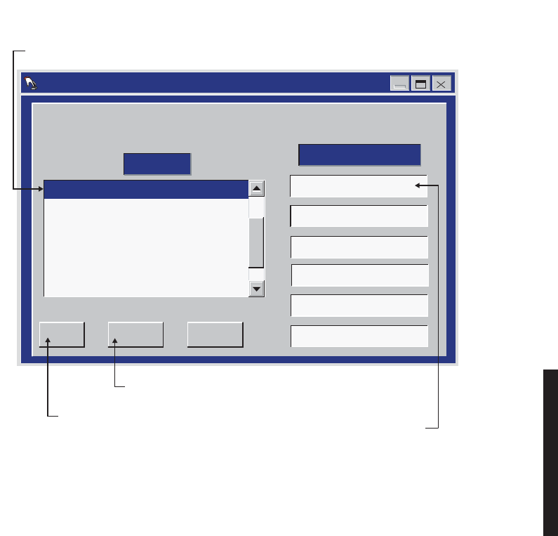
4-47
Figure 4 - 27 Control Names Provisioning
LMW-1021
02/04/03
2. SELECT RADIO
NOTE: DEFAULT CONTROL NAMES ARE USER CONTROL 1-6
User Control Names Setup -- MDR-8000
RACK1 -- DURANGO
RACK2 -- DURANGO
RACK3 -- RED MTH PASS
RACK4 -- SILVERTON
APPLY
OK CANCEL
GEN START
TWR LIGHT OVRD
User Control #3
User Control #4
User Control #5
User Control #6
ELMC List CONTROL NAMES
3. SELECT CONTROL POINT
4. BACKSPACE TO DELETE
AND TYPE IN NEW CONTROL
NAME
CLICK HERE TO CANCEL
TRANSACTIONS
BEFORE SAVE
CLICK HERE
TO SAVE
1. OPEN USER CONTROL NAMES SETUP SCREEN
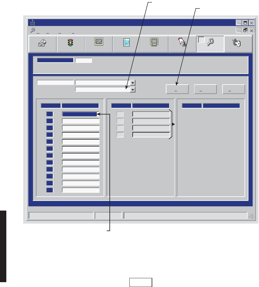
4-48
Figure 4 - 28 Alarm Names Provisioning
DS3 screen is shown. DS1/E1 and OC3/STM-1 alarm names provi-
sioning is similar.
Alcatel User Interface – [Provisioning MDR-8000 OC3]
File View Setup Options
User Control
F8
F6
Performance
Alarm Status
F4
Station Alarm
F7 F9
Prov. Save
F3 F5
Analog Monitor Password
F11
LOCAL DS3 PROVISIONING
Communicating***
ELMC ADDRESS:
ELMC ADDRESS:
S302
LMW-5068
03/29/03
ALARM #
ALARM NAMES
[1]
STATION ALARM #2
[2]
STATION ALARM #3
[3]
STATION ALARM #4
[4]
STATION ALARM #5
[5]
STATION ALARM #6
[6]
STATION ALARM #7
[7]
STATION ALARM #8
[8]
STATION ALARM #9
[9]
STATION ALARM #10
[10]
STATION ALARM #11
[11]
STATION ALARM #12
[12]
ALARM #
ALARM NAMES
STATION ALARM #13
[13]
STATION ALARM #14
[14]
STATION ALARM #15
[15]
STATION ALARM #16
[16]
ALARM #
ALARM NAMES
DS301 -- MDR-8000 DS3
DS301 -- MDR-8000 DS3 OK Cancel Apply
STATION ALARM #1
Monday, August 6, 2001 2:11:32 PM MDR-8000 DS3 Controller Version R1.03
2. SELECT ALARM
3. BACKSPACE TO DELETE
AND TYPE IN NEW ALARM
NAME
1. SELECT RADIO
CLICK HERE TO SAVE
AVAILABLE IF RADIO IS
PROVISIONED STATION ALARM
13-16 FOR SYSTEM ALARM ON
RADIO CONFIGURATION
PROVISIONING SCREEN.
HIDDEN IF RADIO IS
PROVISIONED TBOS DISPLAY
1-8.
Note

5-1
The information contained in this section is a summary of the section
with the same title, but not the same section number, on the enclosed
CD. “Refer to CD” is used throughout this section to refer the reader to
the detail information on the CD. Go to this section on the CD for inter-
active links to the detail information referred to in this section.
5MAINTENANCE
5.1 INTRODUCTION
This section contains information and procedures to aid in restoring the equipment to
its proper operating condition after it has been determined that a problem exists.
The following warnings and cautions apply while operating, performance testing, trouble-
shooting, or repairing the MDR-8000 series radios.
Short circuits in low-voltage, low-impedance dc circuits can cause severe
arcing that may result in burns or eye injury. Remove rings, watches, and
other metal jewelry while working with primary circuits. Exercise caution
to avoid shorting power input terminals.
XMTR Crystals should never be shipped as replacements without being
soldered and tuned up in an oscillator assembly board at the factory.
Units with the electrostatic-sensitive (ESS) symbol contain ESS
devices. Store these units in an antistatic container when not in use,
and anyone handling a unit should observe antistatic precautions.
Refer to the Special Precautions pages in the front of the instruction
book for detailed handling information.
Note
DANGER
Possibility of
Injury
to Personnel
CAUTION
Possibility of
Service
Interruption
CAUTION
Possibility of
Service
Interruption

5-2
RF flex coaxial cable requires special consideration. The electrical char-
acteristics of the coax can be affected if it is accidentally twisted or bent.
Provide mechanical support to prevent any weight or strain to the coax
and connector when connecting or disconnecting equipment. Loosen the
connectors at both ends of a coax section if one end must be moved even
slightly. SMA connectors should be secured in place fingertight, and
then gently tightened using a torque wrench with a 5/16 in. head set for 7
to 9 inch-pounds. The connectors should not be left fingertight.
Ensure that all antennas are properly aligned and waveguide is in
good physical condition.
Before performing procedures that might in any way affect transmis-
sion, it is recommended that the person performing the procedure
understand the FCC Rules and Regulations pertaining to the equip-
ment and be properly authorized to operate the equipment.
5.2 MAINTENANCE PHILOSOPHY
This section provides information and procedures for equipment maintenance down to the
module level. Module repair is not covered in this manual. A replacement procedure for the
crystal oscillator subboard on the transmitter and receiver modules is provided to enable
future use of the local oscillator at a different frequency in another application or at
another location. Use the drawings in the appendix and those in the station drawing pack-
age to support the procedures in this section
The use of maintenance procedures in this section may result from failure of a periodic
check, an alarm indication, or unacceptable performance. These problems should normally
be resolved as shown in the maintenance philosophy flow chart (Figure 5 - 1).
CAUTION
Possibility of
Service
Interruption
Note
Note
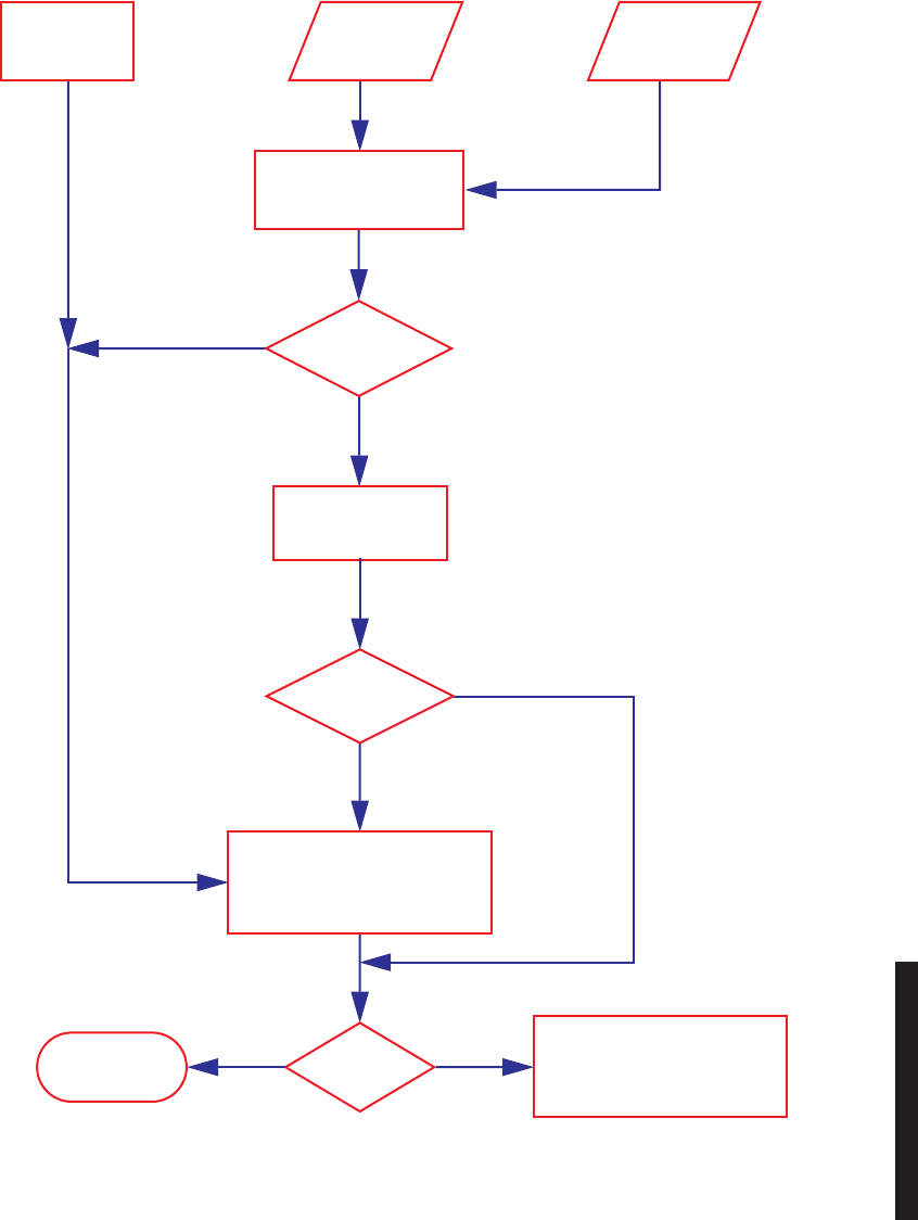
5-3
Figure 5 - 1 Maintenance Philosophy Flow Chart
Periodic Check
Failure*
Para. 5.8
Performance
Screen Errors
Para. 5.9.3
Cause
of
Alarm
Refer to Module
Replacement Table
Table 5 - 6
Module
Adjustment
Required
Perform Applicable Checks and
Adjustments Per Module
Replacement Table
Table 5 - 6
Problem
Resolved
Perform additional trouble-
shooting using Theory and
Diagrams sections as required
to resolve Problem
Maintenance
Complete
Checks and Adjustments
Required
No
NoYes
Yes
Alarm
Indication
Para. 5.6
Module Replacement
Required
Perform
Trouble Analysis
Para. 5.9

5-4
5.3 RECOMMENDED TEST EQUIPMENT
Refer to Table 5 - 1 for the list of recommended test equipment. Alcatel recommends this
test equipment to properly maintain the radio.
5.4 OPTIONAL TEST EQUIPMENT
Refer to Table 5 - 2 for a list of optional test equipment to support alternate test procedures
in this section and the over-the-hop test procedure (Refer to CD).
Table 5 - 1 Recommended Test Equipment
Test Equipment/Function
Essential Characteristics
Used On
Digital Volt Meter (DVM)
Fluke 75 Out-of-Service Carrier Null Adjustment
Using DVM (Refer to CD).
Frequency Counter,
Agilent 5315A 106 to 150 MHz Para. 5.18, XMT Crystal Oscillator Fre-
quency Correction
Para. 5.23, RCV Crystal Oscillator Fre-
quency Correction
Power Meter, Agilent
E4418A with E4418B
Power Sensor E9300A
-60 to +20 dBm, 10 MHz
to 18 GHz, 50 ohms Para. 5.21, XMTR Output Level Calibration
(No PA)
Para. 5.25, PA Output Level Calibration
Test Lead and Tool Kit PN 695-0675-003 As Required
Table 5 - 2 Optional Test Equipment
Test Equipment/Function
Essential Characteristics
Used On
Adapter
Type N Male Interface
Adapter
(Qty. 2 Required)
Tyco Electronics
1048789-1
Flexible RF Test Cable
Attenuator
Narda 768-30 30 dB, 50 Ohms, 20
Watts Para. 5.25, PA Output Level Calibration (Alternate Procedure)
Bit Error Rate Test Set
Acterna ANT-5
Data Rate
Modulation Scheme 2.048 Mb/s,
HDB3
Over-The-Hop E1 BER Threshold Test

5-5
5.5 PERSONAL COMPUTER (PC)/LAPTOP
The PC is an on-line maintenance and troubleshooting tool. Refer to the General Section
for PC guidelines. See Figure 5 - 2. Connect the RS-232 Interface cable between USI con-
nector on controller and the PC.
Communications Ana-
lyzer w/DS1 Package
Acterna TB 2310-P4
D1 Data Rate
DS1 Modulation
Scheme
1.544 Mb/s,
B8ZS or AMI
Over-The-Hop DS1 BER Threshold Test
Communications Ana-
lyzer w/DS3 Package
Acterna TB 2310-P5
DS3 Data Rate
DS3 Modulation
Scheme
44.736 Mb/s,
64 QAM
Over-The-Hop DS3 BER Threshold Test
Communications Ana-
lyzer w/OC3 Package
Acterna TB 2310-P2 155.52 Mb/s
Over-The-Hop OC3/STM-1 BER Threshold
Test
Flexible RF Test Cable, 6
Ft.
Tyco Electronics
1049982-5
Spectrum Analyzer
Optical Power Meter
RIFOCS 555B with SC
and FC SOC
Power
Wavelength -8 to -28 dBM,
1310/1550 nm
Over-The-Hop Optical Power Test
Oscilloscope, Tektronix
TDS3052B DS3 Radio DADE
DS3 Line DADE
Spectrum Analyzer, Agi-
lent E4408B 1.7 to 11.7 GHz Para. 5.20, In-Service XMTR Carrier Null
Adjustment Using Spectrum Analyzer
Variable Attenuator,
Narda 791 1.7 to 11.7 GHz, 0 to
37.5 dB
Over-The-Hop DS1 BER Threshold Test
,
Over-The-Hop E1 BER Threshold Test,
Over-The-Hop DS3 BER Threshold Test,
Over-The-Hop OC3/STM-1 BER Threshold
Test, OC3/STM-1/ETH I/O Interface
Removal and Replacement,
Over-The-Hop OC3/STM-1 Fade Margin
Test (to the 10-6/10-3 BER Level)
Table 5 - 2 Optional Test Equipment (Cont.)
Test Equipment/Function
Essential Characteristics
Used On
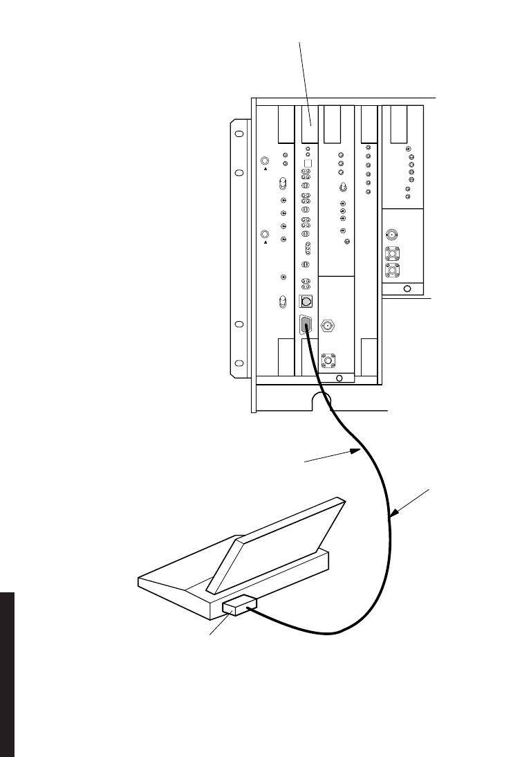
5-6
Figure 5 - 2 USI Computer to Controller Interconnection
MW211–0066–1
101598
AE–37( )
CNTLR
C1
RS–232C PORT
RS–232C
INTERFACE CABLE
USI
TERMINAL
TO CONNECTOR J301
(CONNECTS TO
AE–37 CONTROLLER)
MDR–8000
SHELF

5-7
5.6 MDR-8000 ALARMS
MDR-8000 Alarms are displayed on:
1USI Alarm and Status screen
2Alcatel MCS-11 Monitor and Control System
3SNMP MIB browser
4TBOS foreign alarm system
5External relay interface
6Module front panel indicators
Alarm names are radio/alarm equipment dependent. The Alarm List found under NOC
Alarm Troubleshooting on the enclosed CD, identifies every alarm name indicated by the
above alarm display equipment, in alphabetic order. By clicking on the alarm name, the
user can go straight to the description, cause, effect, and action for that alarm, regardless
of where the alarm is displayed. The alarm list is a summary of alarms designed for use by
NOC personnel. Refer to the detail troubleshooting later in this section for more informa-
tion.
5.7 ALARM MONITORING AND INSPECTION
Perform the following checks whenever a station is entered:
1Verify that no alarms are lighted; only the green status indicators should be
lighted.
2Momentarily press LAMP TEST switch. Verify all indicators light.
Keeping records of errors and alarm history can be an aid to system
troubleshooting.
The local status alarms screen displays the alarms of the radio to
which the USI is connected, either physically or addressed via the
ELMC.
3Using the USI computer, check local alarms on the Local Status Alarms
screen.
Note
Note

5-8
5.8 RECOMMENDED PERIODIC CHECKS
Perform XMTR local oscillator frequency verification (Para. 5.18) and XMTR output check
(Para. 5.19) 1 year after initial setting and at 5-year intervals thereafter to correct possible
drift caused by aging.
5.9 RADIO TROUBLESHOOTING
The digital radio system is equipped with alarm circuitry and automatic switching (in hot-
standby, frequency diversity, and space diversity configurations) to provide protection
against loss of traffic. This automatic switching, coupled with adaptive equalization of mul-
tipath distortion, provides protection against equipment outage and propagation varia-
tions. Because of the finite life of electronic equipment, failures occur.
5.9.1 Troubleshooting USI Alarms
First alert for an alarm is normally the USI Status Alarm Screen. See Figure 5 - 3 through
Figure 5 - 12 for detailed alarm information and troubleshooting guidelines. After isolating
the fault to the most probable cause, replace module or repair as directed.
5.9.2 Troubleshooting RCVR Lockup Problems
The radio is operational when the RCVR is locked onto the associated farend XMTR fre-
quency. Normally lockup occurs within minutes after power is applied. Successful lockup is
indicated by not having the channel alarm (Chan Alm) lit on the RCVR front panel.
5.9.2.1 Slow Lockup At Initial Turnup
Slow lockup at initial turnup is defined as lockup occurring five minutes or more after pow-
erup. If the radio is non-standby/no space diversity (one RCVR in A side), replace the
RCVR. If radio is non-standby space diversity or hot-standby (two RCVRs, A and B sides)
problem is probably the XMTR at the farend of the hop. The most common cause of slow
lockup is incorrect carrier null. First try switching XMTRs. If this clears the problem, per-
form carrier null (Para. 5.20) and XMTR/PA output level calibration procedure (Para. 5.21)
on the off-line XMTR. If the problem is not cleared, replace the XMTR.
5.9.2.2 Slow Lockup During Normal Operation
Slow lockup after a bad fade or other temporary interruption is defined as lockup occurring
less than a second after RSL is restored. Troubleshooting this type of slow lockup requires
knowing what the RSL is. Check RSL using the procedure in Appendix G on attached CD.
If the RSL is at least 4 to 5 dB above RCV threshold, the two most probable causes are carrier
leakage and the RCVR local oscillator. Perform carrier null test (
Para. 5.20
) on the farend
XMTR. If slow lockup continues, remove and replace the RCVR crystal oscillator subboard.
If the RSL is below or 1 to 3 dB above RCVR threshold, wait until RSL improves to at least
4 to 5 dB above RCVR threshold before starting troubleshooting.

5-9
5.9.3 Troubleshooting Performance Screen Errors
Path and intermod problems can occur that cause errors to be indicated on the Perfor-
mance monitor screens that are not severe enough to generate an alarm on the USI Alarm
and Status screen. Errors of this type fall into two categories: burst and dribbling errors.
The performance screens can be a useful tool in troubleshooting a radio with and without
alarms being indicated on the Status Alarm screen.
5.9.3.1 Troubleshooting Burst Errors
Burst errors are defined as multiple errors in a very short time. Burst errors can be caused
by many things, including loose connections on cable or waveguide at either end of the hop.
An aging oscillator can cause burst type errors. Burst errors can be identified by a high
number of Errors and low number of Error Seconds on the Performance screens. The
most probable cause of burst errors is a loose connection. Check/repair all shelf and exter-
nal cables and check all waveguide connections The next most probable cause is the crystal
on the crystal oscillator subboard at either end of the hop.If the radio has both A and B
XMTRS and RCVRS and both A and B are indicating burst errors, the fault is at the XMT
end of the hop. If only A is equipped and indicates burst errors, remove and replace the
crystal oscillator subboard on the on-line RCVR.
5.9.3.2 Troubleshooting Dribbling Errors
Dribbling errors are defined as small number of errors over long period of time (no frame
errors). Dribbling errors can be caused by a path problem, such as interference or fading,
or by a hardware problem such as a XMTR or PA that is being over driven, or high phase
noise in the XMTR or RCVR oscillator. Dribbling errors can be identified by observing the
Radio CRC Errors (DS1), Radio Errors (DS3), Receiver Errors (OC3), or RF Receiver
Errors (ETH) fields on the radio Performance screen. Typically, less than five Errors to one
Error Second identifies the fault as dribbling errors. Try isolating the transmitter by
switching transmitters in a protected system. You can further isolate a transmitter by
changing output levels using ATPC and or dropping the output power out of the XMTR to
the PA by one or two dB.
The DS1 radio performance screen has a Repeater CRC Error Sec field that indicates
errors over the repeater cable.
Two troubleshooting tips: 1) errors are displayed on the USI at the receive end in which
they are detected, and 2) these specific type of radio errors are not propagated down the
path.
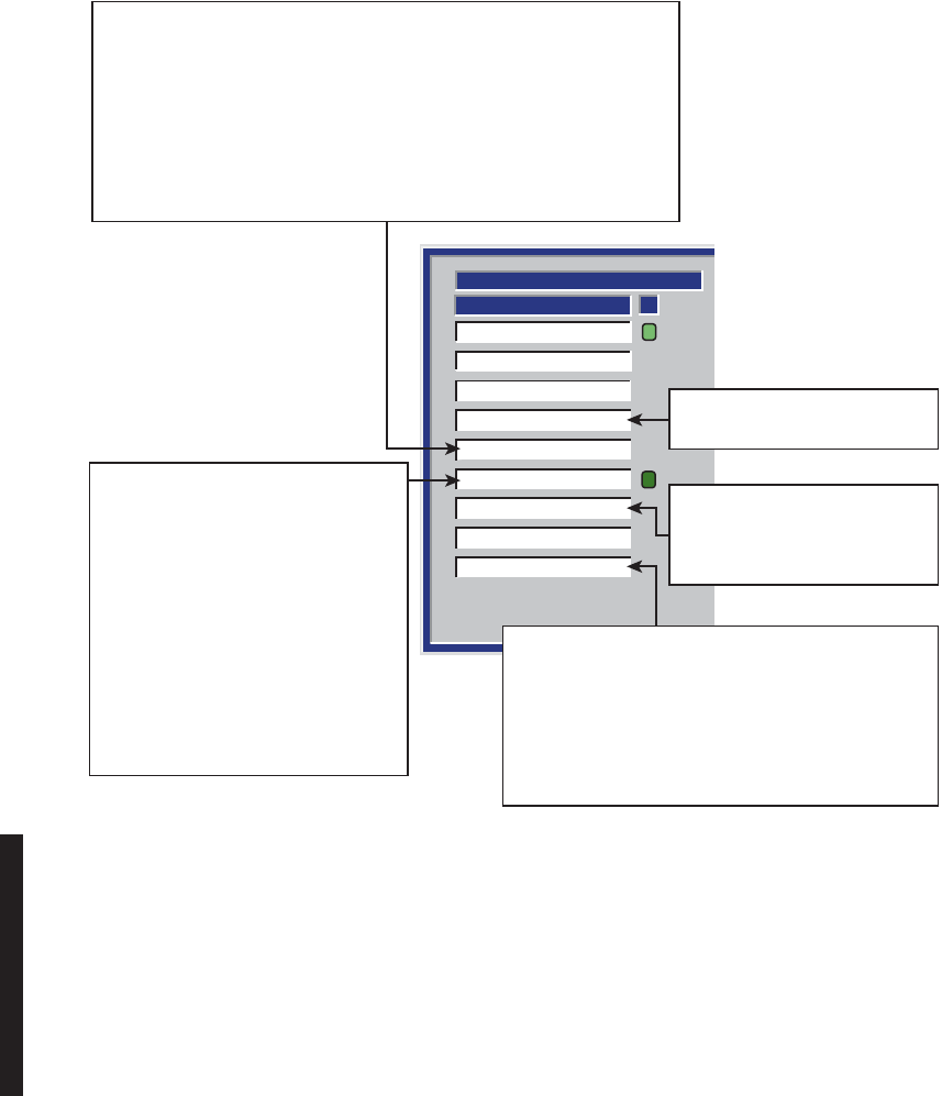
5-10
Figure 5 - 3 Troubleshooting Radio XMT Alarms (Sheet 1 of 2)
TRANSMITTER
Transmitter Fault
Transmitter OnLine
STATUS
A
RF Common Loss
PA Temperature
PA RF Power
Transmitter RF Power
ATPC High Power
ATPC Timeout
Sync Loss
PA temperature limits exceeded.
Check mounting screws.
ATPC has been active for 5 minutes
without returning to normal (drops
back to low power only if ATPC has
been enabled with timeout).
Loss of XMT signal detected at output of PA. If any other alarms are red, go to 1.
If not, go to 2.
1. If Off Normal alarm is lit, check 10.5 V switch on power supply is on. If not,
remove/replace PA module.
2.
Measure RF level at RF MON connector on XMTR module. If level is low, go
to 3. If not, go to 4.
3. Measure frequency at XTAL MON connector on XMTR module. If frequency
is correct, remove/replace XMTR module. If not, remove/replace XTAL
Oscillator Subboard.
4. Remove/replace PA module.
Loss of XMT signal detected at output of
PA. If I/O common alarm and XMT
Sync
Loss alarm are red, go to 1. If not,
go to 2.
1. Remove/replace I/O Interface
module.
2. Measure RF level at RF MON
connector on XMTR module. If level
is low, go to 3. If not, go to 4.
3. Measure frequency at XTAL MON
connector on XMTR module. If
frequency is correct, remove/
replace XMTR module. If not,
remove/replace XTAL oscillator
subboard.
4. Remove/replace PA module.
In protected systems, indicates failure in synchronization
between I/O Interface modules. If I/O Interface module
in-service is not active on alarmed side, failure is between
A and B I/O Interface modules. If I/O Interface module
in-service is active, failure is between repeater racks of
synchronous repeater.
1. Replace A-side I/O Interface module.
2. Replace B-side I/O Interface module.
MDR-1093
10/09/05
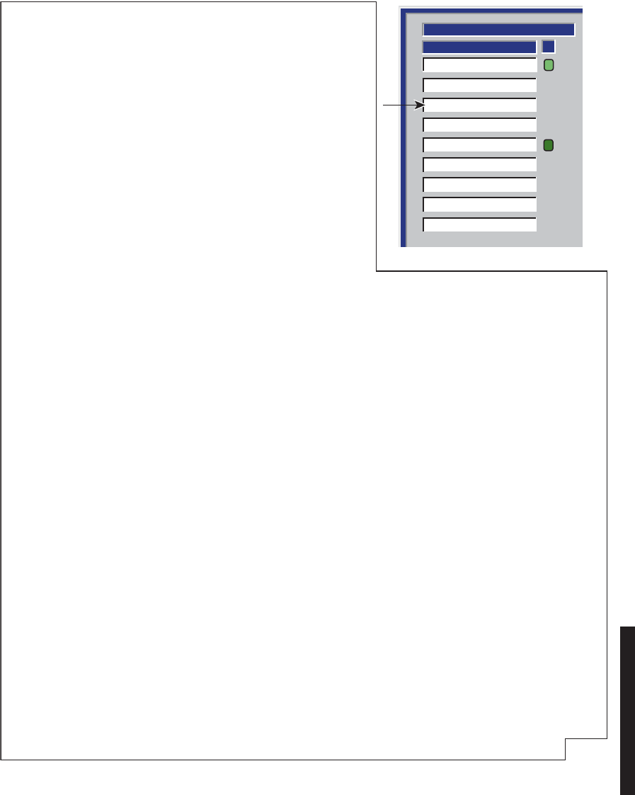
5-11
Figure 5 - 3 Troubleshooting Radio XMT Alarms (Sheet 2 of 2)
TRANSMITTER
Transmitter Fault
STATUS
A
Transmitter OnLine
RF Common Loss
PA Temperature
PA RF Power
Transmitter RF Power
ATPC High Power
ATPC Timeout
Sync Loss
In DS1 and OC3/STM-1 2-fiber switched and 4-fiber switched radios, if the RCVR alarms do not clear within the CLA window, after
ten 30-second periods (10 switches) the controller switches the I/O Interface modules and another 5-second CLA window is
opened. If the RCVR alarms clear during the 5-second CLA window following the I/O switch, the CLA will activate at the XMT end.
1. If RSL is ok, look for a digital signal problem at the farend XMTR:
a. Check XMTR capacity key.
b. Remove/replace XMTR.
c. Remove/replace I/O Interface.
2. If RSL is low, there will be a RCVR RSL alarm along with any others:
a. Check for prolonged fade. Use USI RSL screen and check history. Worst fading times are early in the morning and
late in the evening.
b. Look for equipment failure at XMT end:
Check for bad XMTR/PA. Verify correct output power out of XMTR/PA. Is output power correct?
Yes, check for bad cable or RF switch at the XMT end.
No, remove and replace XMTR, PA, I/O Interface, in that order.
CLA can be caused by many things. Troubleshooting is RSL dependent. Problems that can cause a CLA follow.
1. Path problems, such as fading, refraction, interference
2. Frequency problems due to aging or bad crystal oscillator
3. Bad capacity key on XMTR
4. Bad RF cable
5. Bad RF switch
6. Bad I/O Interface
If RSL is normal, look for a digital signal problem at the XMT end. The RCV end will probably have Eye Closure and Frame
Loss alarms, but not an RSL alarm. Since the RCVRs are receiving a strong signal (but not a good signal) from the farend
XMTR, the RCVRs will probably be locked on frequency.
Is RSL above or below alarm threshold?
Above, go to 1.
Below, go to 2.
Clearing the RCVR problem does not automatically clear the CLA at the XMT end. The CLA can be cleared using the ACO
switch on the controller module or by rolling the mouse over RF Common Loss on the screen and double clicking.
Since this is a silent alarm at the XMT end, no other alarm should show up at the XMTR.
Both RCVRs at the other end have a problem and have switched the
XMTRs to try and clear it. If the RCVRs clear within a defined time frame
(which we will hereafter call the CLA window) after switching, the CLA
appears. if the RCVRs clear by switching or any other way outside of the
CLA window, the CLA does not activate, but switching continues.
If RSL is above alarm threshold, the first XMT switch occurs 5 seconds
after the problem at the RCVRs is detected. The 5 seconds following the
first XMT switch is the "CLA window". If the RCVR alarms clear during the
5-second CLA window, the CLA will activate at the XMT end.
Since the RSL at the RCVRs is ok, equipment failure at the farend XMTR is
the most probable cause of the RCVRs failing.
If RSL is below alarm threshold, the first XMTR switch occurs 30 seconds
after the problem at the RCVRs is detected. The CLA window is the first 5
seconds of the second 30 seconds. If the RCVR alarms clear during the
5-second CLA window, the CLA will activate at the XMT end.
Switching times vary, depending on RSL.
MDR-1092
12/06/07
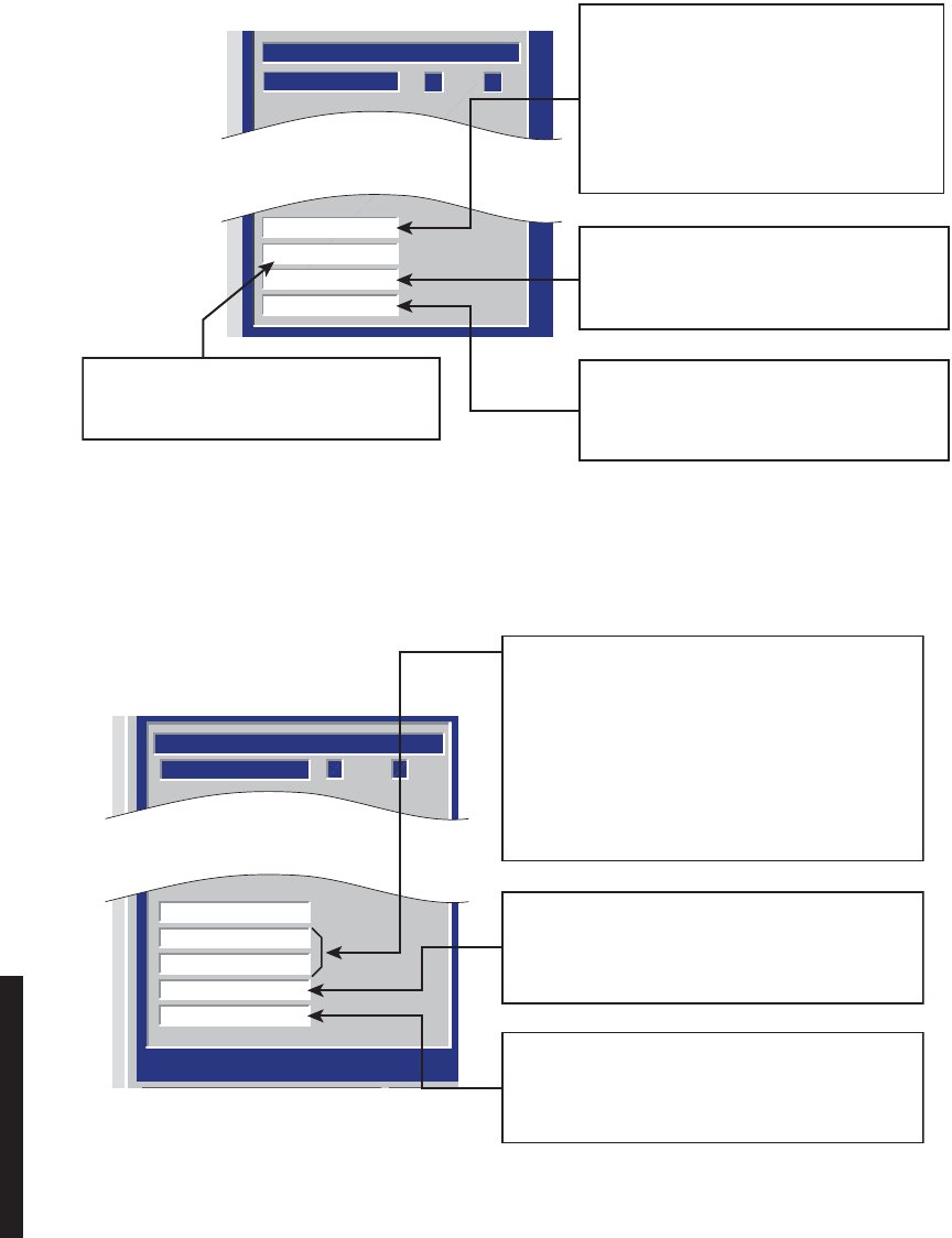
5-12
Figure 5 - 4 Troubleshooting DS3 Radio XMT Alarms
Figure 5 - 5 Troubleshooting OC3/STM-1 Radio XMT Alarm
A B
TRANSMITTER
DS3 Frame Loss
DS3 Buffer Spill
DS3 Degraded
DS3 AIS Detect
STATUS
DS3 I/O INTFC cannot recover framing
from incoming DS3 signal or there is no
input signal. Is DS3 AIS Detect Alarm on?
Yes, troubleshoot upstream radios and
external MUX equipment.
No, check input signal. If input signal is
OK, replace DS3 I/O INTFC. If not,
troubleshoot external MUX equipment.
DS3 input to DS3 I/O INTFC has exceeded
provisioned BER threshold (high error
condition).Troubleshoot external MUX
equipment.
DS3 input data being written to elastic buffer
on DS3 I/O interface is a different rate than
the data being read from elastic
buffer.
AIS (blue signal), inserted at MUX (external
to the radio) has been detected on XMT input
to DS3 I/O INTFC.
Troubleshoot external MUX equipment.
MDR-1090
05/25/07
A B
TRANSMITTER
OC3 Input Online
OC3 LOS
OC3 LOF
OC3 AIS-L Detect
OC3 Degrade
STATUS
Monday, April 09, 2001 1:58:29 PM
OC3/STM-1 INTFC cannot recover framing from
incoming OC3/STM-1 signal or there is no optical
input signal.
Is OC3/STM-1 AIS-L Detect alarm on?
Yes, troubleshoot upstream radios and external
MUX equipment.
No, check optical input signal. If optical input
signal is OK, replace OC3/STM-1 I/O INTFC. If not,
troubleshoot external MUX equipment.
OC3/STM-1 input to OC3/STM-1 I/O INTFC has
exceeded provisioned BER threshold (high error
condition).
Troubleshoot external MUX equipment.
AIS (blue signal), inserted at MUX (external to the
radio) has been detected on OC3/STM-1 input to
OC3/STM-1 I/O INTFC.
Troubleshoot external MUX equipment.
MDR-1091
05/23/05
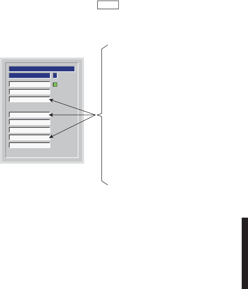
5-13
Figure 5 - 6 Troubleshooting Radio RCV Alarms (Sheet 1 of 5)
ASTATUS
Receiver Fault
Receiver On Line
Channel Fail
Radio Dade
Eye Closure
Low RSL
Path Distortion
Radio Frame Loss
RECEIVER
Note
Always troubleshoot and clear the most severe alarm first.
Channel Fail is the most severe, followed by Radio Frame Loss
and Eye Closure.
The Eye Closure alarm, Radio Frame Loss
alarm, and Channel Fail alarm all work together
to form effective 3-level troubleshooting tools. If
the radio is provsioned correctly, Eye Closure
(the first level) should be the first indication that
there is a steady stream of errors (more than
dribbling errors) being detected by the RCV
circuit in the I/O Interface module. The second
level is the Radio Frame Loss alarm. This alarm
indicates that the errors have increased to the
point that complete frames are being lost. The
third level, the Channel Fail alarm, is the most
severe level. This alarm indicates that the RCVR
can no longer lock on the farend XMTR. Even
worse, the overhead with command path and
Service Channel is lost, inhibiting communication
with the farend, making troubleshooting more
difficult.
MDR-1081
05/20/05
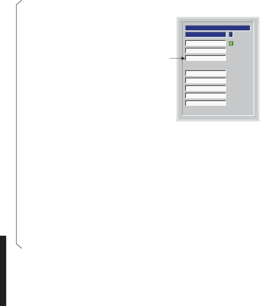
5-14
Figure 5 - 6 Troubleshooting Radio RCV Alarms (Sheet 2 of 5)
ASTATUS
Receiver Fault
Receiver On Line
Channel Fail
Radio Dade
Eye Closure
Low RSL
Path Distortion
Radio Frame Loss
RECEIVER
MDR-1084
11/29/04
A Channel Fail alarm occurs when RCVR(s) have lost lock and are not
locked on the signal from the farend XMTR(s). Loss of signal also means
loss of CMD path. The most effective method of troubleshooting this type
alarm is to have a technician at both ends of the hop. Farend status
viewing and controls must be performed at the farend site. This alarm can
be caused by a failure at the farend XMTR, RF path/antenna/waveguide
problems, or a failure in the local RCVR or I/O Interface.
Start by isolating the fault to one end of the hop or the RF
path/antenna/waveguide. If the farend XMTR is protected, switch XMTRs
and see if alarms at the RCVR end clear. If so, the problem is at the XMT
end and the path and RCV end are ok. If the RCVR alarms do not clear
(and/or the XMTR is not protected) proceed as follows:
1.
Observe RX (RSL 1) dbm on the analog monitor screen and compare the RSL level with the TYPICAL
RCVR THRESHOLD (DBM) BER = 10-6, for the type and capacity of radio, listed on Tabe 1-3, Physical,
Environmental, and Electrical Characteristics, in the General section of this instruction book. If the RSL is
too low (below the RCVR threshold), the RCVR will not lock to the farend XMTR. The problem is in the
farend XMTR, is an RF path problem, or is a farend or local antenna/waveguide problem.
2.
Troubleshoot farend XMTR.
If the RSL is above the listed threshold, troubleshoot the local RCVR. Start by isolating the fault to the RCVR
module or I/O Interface module.
a. Observe
RX (AFC MON)
voltage on the analog monitor screen. This is the correction voltage for the
crystal oscillator. The voltage should be -3.0 ±0.5 Vdc, indicating that the crystal oscillator is on center
frequency. If not, remove and replace crystal oscillator subboard on RCVR. If the
RX (AFC MON)
voltage is correct, the failure could still be the RCVR or the RCVR circuits in the I/O Interface module.
The most probable cause is the RCVR.
b. Remove and replace RCVR. The crystal oscillator subboard and capacity key must be removed from
the suspected RCVR and installed on the spare RCVR. If the alarm is stil not cleared, remove and
replace the I/O Interface module.
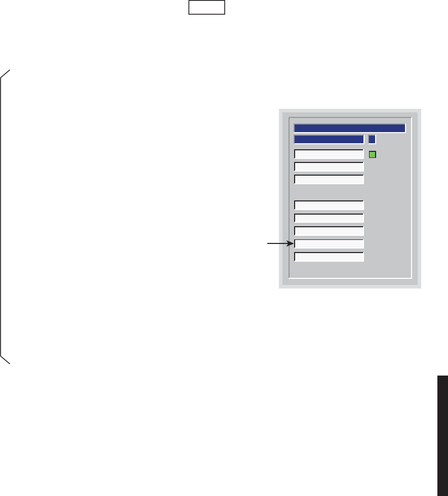
5-15
Figure 5 - 6 Troubleshooting Radio RCV Alarms (Sheet 3 of 5)
ASTATUS
Receiver Fault
Receiver On Line
Channel Fail
Radio Dade
Eye Closure
Low RSL
Path Distortion
Radio Frame Loss
RECEIVER
MDR-1083
05/20/05
Loss of radio frame from RCVR in I/O Interface RCVR circuits. Before
starting, check USI for receiver Channel Fail alarms and Common
Command Path alarm. If there is a Channel Fail alarm, troubleshoot and
clear that alarm first. If there is a Command Path alarm, troubleshoot and
clear that alarm second.
1. Verify farend radio configuration. Is farend radio hot-standby?
Yes, go to 2.
No, go to 4.
2. Check for Radio Frame Loss alarms on both A and B.
Are there Radio Frame Loss radio frame loss alarms on both A
and B?
Yes, go to 3.
No, only A or B has a frame loss alarm, go to 4.
3. Switch farend XMTRs. Do alarms clear?
Yes, replace farend off-line XMTR.
No, replace local I/O Interface on alarmed side. Do alarms clear?
Yes, stop. Procedure is complete.
No, replace local RCVR on alarmed side.
4. Replace local I/O Interface on alarmed side. Do alarms clear?
Yes, stop. Procedure is complete.
No, replace local RCVR on alarmed side.
Note
Always troubleshoot and clear the most severe alarm first.
Channel Fail is the most severe, followed by Radio Frame
Loss and Eye Closure.
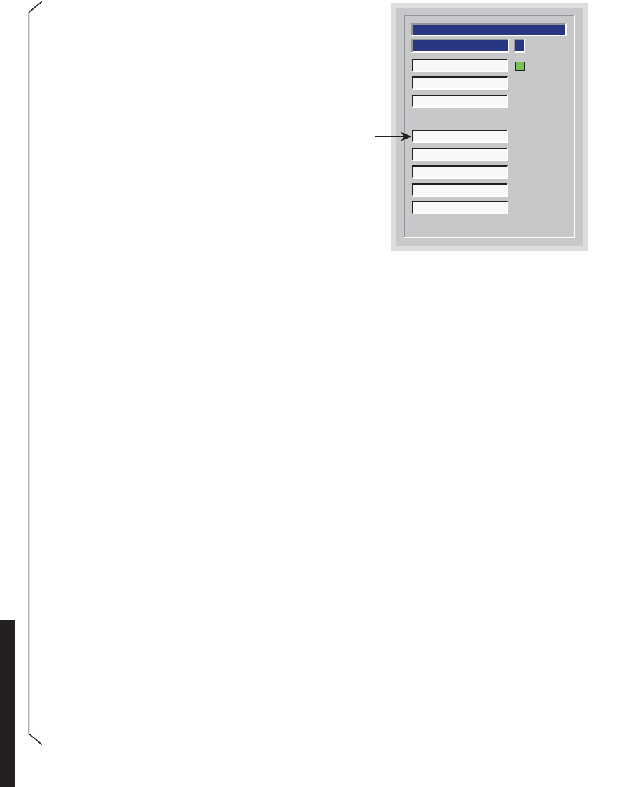
5-16
Figure 5 - 6 Troubleshooting Radio RCV Alarms (Sheet 4 of 5)
ASTATUS
Receiver Fault
Receiver On Line
Channel Fail
Radio Dade
Eye Closure
Low RSL
Path Distortion
Radio Frame Loss
RECEIVER
MDR-1082
11/29/04
Errors are being received by the RCVR at a rate exceeding the Eye
BER threshold error rate provisioned on the radio configuration
screen. This alarm could be caused by a faulty XMTR (farend), radio
interference on the RF path (RFI), antenna/waveguide problem, or a
faulty antenna/waveguide problem, or a faulty RCVR/RCVR local
oscillator failure. Troubleshooting is configuration dependent.
1. Check for Eye Closure alarms on both A and B RCVRs.
Are there Eye Closure alarms on both A and B RCVRs?
Yes, go to 2.
No, only A or B has an Eye Closure alarm. The failure is on
the RCVR end. Go to 3.
2.
The problem is in the farend XMTR, is an RF path problem, or is
a farend or local antenna/waveguide problem. Start by isolating the fault to one end of the hop or the RF
path/antenna/waveguide.
a. Check farend for XMTR alarms. Troubleshoot and clear alarms (if any) at far end as required. Go to b.
b. Check farend radio XMTR configuration as follows:
Hot-standby XMTRs? Go to c.
Frequency diversity? Go to 4.
Space diversity? Troubleshoot farend XMTR.
c. If the farend XMTR is hot-standby, switch XMTRs and see if alarms at the RCVR end clear.
Do RCVR alarms clear?
Yes, the problem is at the XMT end and the path and RCV end are ok. Replace farend off-line XMTR.
No, the problem is a path problem or a problem at the RCVR. Go to d to isolate the path.
d. The problem may be RF interference (RFI) on the path. While observing the RSL on the RCV end Analog
screen, disable the farend XMTRs.
Does RSL drop at least 25 dB?
No, there is high RFI on the path. Eliminate the RFI source.
Yes, RSL drops 25 dB or more. The problem is a path problem, such as an obstruction in the path, or
a problem with the antenna or waveguide, or is a RCVR problem. Go to 3.
3. Isolate failure to RCVR crystal oscillator subboard or the RCVR module as follows:
a. At RCV end, observe RX (AFC MON) voltage on the analog monitor screen. This is the correction
voltage for the crystal oscillator. The voltage should be -3.0 ±0.5 Vdc, indicating that the crystal oscillator
is on center frequency.
If not, remove and replace crystal oscil lator subboard on RCVR.
If the
RX (AFC MON)
voltage is correct, replace RCVR module.
Do RCVR alarms clear?
Yes, stop. Procedure is complete.
No, go to 4.
4. Problem is in path (not RFI) or antenna/waveguide. Sweep waveguide at both ends of hop. Repair or replace
as required.
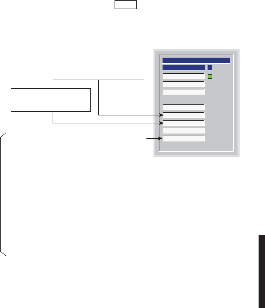
5-17
Figure 5 - 6 Troubleshooting Radio RCV Alarms (Sheet 5 of 5)
ASTATUS
Receiver Fault
Receiver On Line
Channel Fail
Radio Dade
Eye Closure
Low RSL
Path Distortion
Radio Frame Loss
RECEIVER
MDR-1085
11/29/04
More delay in system than elastic buffers on DS1 I/O
Interface can correct.
1. Isolate the delay to local or farend. Delay in the farend XMTR is a possible cause in frequency
diversity configurations. Is the farend radio frequency diversity?
Yes, go to 2.
No, delay is probably a local problem. Go to 3.
2.
Verify there are no farend XMTR alarms. Troubleshoot and clear farend XMTR alarms first.
3. Check/repair waveguide/path.
4. Isolate delay to A-side or B-side I/O Interface. On local controller front panel, observe I/O ALM
indicators. The A or B I/O ALM will be lit for the side with the excessive delay.
5. Remove/replace RCVR on alarmed side.
6. Remove/replace I/O Interface module on alarmed side.
Note
Radio Dade
is displayed on DS1 USI Status and Alarm
screen only.
Low RSL on alarmed RCVR. Alarm only
functions if AGC switching threshold is
provisioned active.
1. Check for path fading.
2. Check upstream XMTR.
High level of distortion in TDE due
to excessive multipath activity.
Check path for interference.
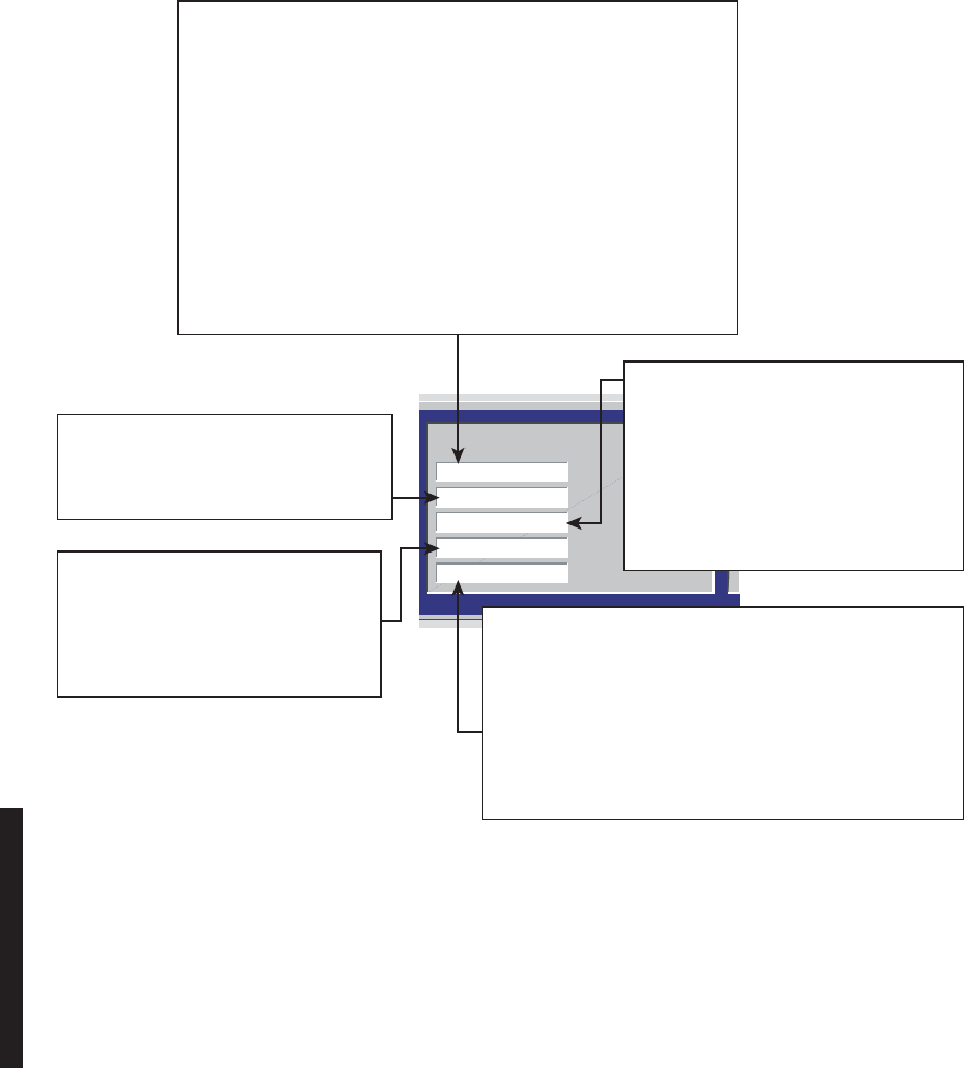
5-18
Figure 5 - 7 Troubleshooting DS3 Radio RCV Alarms
DS3 Frame Loss
DS3 Buffer Spill
DS3 Degraded
DS3 AIS Detect
DS3 AIS Insert
I/O Interface cannot recover framing from signal from RCVR module.
1. Is DS3 AIS Detect alarm on?
Yes, check for upstream XMTR DS3 AIS Detect alarm.
If XMTR
DS3 AIS Detect alarm is on,
troubleshoot external MUX equipment at XMT end.
If not, troubleshoot upstream XMTR. No, go to 2.
2. Is DS3 AIS Ins alarm on?
Yes, check for upstream XMTR alarms. If any XMTR alarm is on,
troubleshoot upstream XMTR. No, go to 3.
3. Is radio hot-standby?
Yes
A. Are A and B alarmed?
Yes, troubleshoot XMTR. No, go to B.
B. Remove/replace RCVR module.
C. Remove/replace alarmed DS3 I/O Interface.
AIS (blue signal), inserted at MUX
(external to the radio) has been
detected by DS3 I/O INTFC RCV
circuits.
Troubleshoot external MUX equipment
(fault is not in radio).
DS3 input data being written to elastic
buffer on DS3 I/O interface is a different
rate than data being read from elastic
buffer.
MDR-1087
05/25/07
LOS has been detected at RCV input of DS3 I/O INTFC
and AIS (blue signal) is being inserted. Check for LOS at
XMTR end of hop.
If not:
1. Check for upstream XMTR alarms. Any XMTR alarms?
Yes, troubleshoot XMTR
No, go to 2.
2. Replace RCVR module on alarmed side.
3. Replace alarmed DS3 I/O INTFC module.
Signal from RCVR module (input to DS3
I/O INTFC) has exceeded provisioned
BER threshold (typical fade condition).
Is DS3 Frame Alarm also on?
Yes, troubleshoot DS3 Frame Alarm.
No, and no-fade condition confirmed
1. Replace RCVR module.
2. Replace alarmed DS3 I/O
INTFC module.
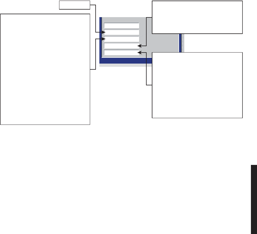
5-19
Figure 5 - 8 Troubleshooting OC3/STM-1 Radio RCV Alarms
OC3 Output Online
OC3 Common Loss
OC3 LOF
OC3 AIS-L Detect
OC3 Degrade
Future use
I/O conditioner cannot recover framing
from signal from RCVR module.
1. Is OC3/STM-1 AIS-L Detect alarm
on?
Yes, check for upstream XMTR
OC3/STM-1 AIS-L Detect alarm.
If XMTR OC3 AIS Detect alarm is on,
troubleshoot external MUX equipment
at XMT end.
If not, troubleshoot
upstream XMTR.
No, go to 2.
2. Is radio hot-STBY?
Yes
A. Are A and B alarmed?
Yes, troubleshoot XMTR.
No, go to B.
B. Remove/replace RCVR module.
C. Remove/replace alarmed
OC3/STM-1 I/O INTFC.
MDR-1088
05/23/05
Signal from RCVR module (input to
OC3/STM-1 I/O INTFC) has exceeded
provisioned BER threshold (typical fade
condition).
Is
OC3/STM-1
LOF also on?
Yes, troubleshoot OC3/STM-1 LOF.
No, and no-fade condition confirmed
1. Replace RCVR module.
2. Replace alarmed
OC3/STM-1 I/O INTFC
module.
AIS (blue signal), inserted at MUX
(external to the radio) has been detected
by OC3/STM-1 I/O INTFC RCV circuits.
Troubleshoot external MUX equipment
(fault is not in radio).
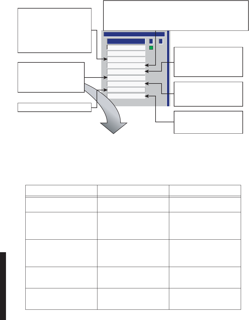
5-20
Figure 5 - 9 Troubleshooting Radio Common Alarms
MESSAGE MEANING ACTIONS
Fan Alarm Fan or fan control module
failed. Remove/replace fan/fan
assembly.
A ATPC High Power Lock A ATPC High Power Lock func-
tion is enabled on USI control
screen locking A-side XMTR/
PA at highest power.
Disable
A ATPC High Power Lock
function on USI control screen.
B ATPC High Power Lock B ATPC High Power Lock func-
tion is enabled on USI control
screen locking B-side XMTR/
PA at highest power.
Disable B ATPC High Power Lock
function on USI control screen.
A ATPC Low Power Lock Locks A-side XMTR/PA output
power 10 dB down from high-
est power.
Disable A ATPC Low Power Lock
function on USI control screen.
B ATPC Low Power Lock Locks B-side XMTR/PA output
power 10 dB down from high-
est power.
Disable B ATPC Low Power Lock
function on USI control screen.
Previous Section
Ring Broke
I/O On Line
Power Supply
Inventory
Command Path
Off Normal
Controller
I/O Interface Fault
A B
COMMON
STATUS
Voltage regulation failure or
excessive load.
1. Cycle power
2. Check fuse
3. Check output power
4. Replace power supply.
Module is present, but cannot communicate with Controller on I2C Bus.
1. Remove and replace module indicating read fail on Inventory
screen.
2. Remove and replace Controller.
Equipment malfunction within ring.
Click red alarm indicator. Drop
down list displays one or more
messages.
Troubleshoot as follows. Controller Module failure.
1. Reseat Controller
2. Replace controller.
Loss of communication between
Controller and farend Controller.
1. Verify RCVR operation
2. Replace Controller.
Failure of RCVR in Previous
Section of synchronous
repeater configuration.
MDR-1089A
12/05/04
SEE
TABLE
BELOW

5-21
A Tx Override Override function is enabled
on controller module locking A-
side XMTR/PA in-service.
Switching is disabled regard-
less of alarms.
Disable override function on
controller module front panel.
B Tx Override Override function is enabled
on controller module locking B-
side XMTR/PA in-service.
Switching is disabled regard-
less of alarms.
Disable override function on
controller module front panel.
A Rx Override Override function is enabled
on controller module locking A-
side RCVR in-service. Switch-
ing is disabled regardless of
alarms.
Disable override function on
controller module front panel.
B Rx Override Override function is enabled
on controller module locking B-
side RCVR in-service. Switch-
ing is disabled regardless of
alarms.
Disable override function on
controller module front panel.
A I/O Override Override function is enabled
on controller module locking A-
side I/O interface in-service.
Switching is disabled regard-
less of alarms.
Disable override function on
controller module front panel.
B I/O Override Override function is enabled
on controller module locking B-
side I/O interface in-service.
Switching is disabled regard-
less of alarms.
Disable override function on
controller module front panel.
Calibrating A Side A-side XMTR/PA output level
calibration procedure has
been initiated.
Complete or cancel A-side
XMTR/PA output level calibra-
tion procedure.
Calibrating B Side B-side XMTR/PA output level
calibration procedure has
been initiated.
Complete or cancel B-side
XMTR/PA output level calibra-
tion procedure.
Pedestal Switch Activated PED/AC/NORM switch on front
panel of original/older style
RCVR is set to PED.
Set PED/AC/NORM switch to
NORM.
DS1 Loopback On DS1/wayside DS1 line and/or
facility loopback function is
enabled on USI control screen.
Disable loopback functions on
USI control screen.
A Side PA OFF PA ON/OFF switch on A-side
power supply is set to OFF.Set PA ON/OFF switch on A-
side power supply to OFF.
MESSAGE MEANING ACTIONS
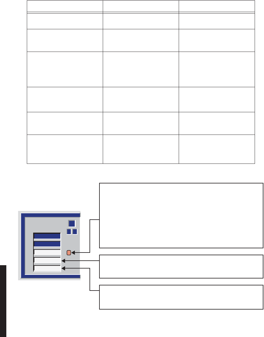
5-22
Figure 5 - 10 Troubleshooting DS1/E1 Radio Alarms
B Side PA OFF PA ON/OFF switch on B-side
power supply is set to OFF.Set PA ON/OFF switch on B-
side power supply to OFF.
Prov. Mismatch Provisioning on the controller
does not match the provision-
ing screen.
Provision to match system
requirements.
Controller/Power Supply Prov.
Mismatch Provisioning data stored in
memory on the controller does
not match provisioning data
stored in memory on the A-side
power supply.
Check for correct provisioning.
Reprovision as required. Save
provisioning.
Could Not Write/Read Power
Supply Prov. Cannot download provision-
ing data from controller to A-
side power supply.
Remove/replace:
1. A-side power supply
2. Controller.
Capkey Mismatch Capacity key on A-side XMTR
has different part number than
capacity key n B-side XMTR.
Instal correct capacity keys on
XMTRs.
Radio ID Mismatch Radio IDs provisioned on the
radio configuration screen are
not the same at both ends of
the hop.
Provision both ends of hop
with same radio ID number.
MESSAGE MEANING ACTIONS
A B
1
DS1 LINE #
SIDES
TX SIG
TX ALM
RX ALM
LMW-1030
04/07/05
Loss of input signal to I/O Interface, inability to recover clock on alarmed
line, or bipolar violation detection
1. Check presence and quality of DS1/E1 input to radio
2. Enable DS1 I/O Loopback on USI control screen for continuity check
for DS1 signal through LBO and I/O interface module.
Continuity?
Yes – replace I/O interface
No – check LBO connectors for open or bent pins.
Repair as required.
Transmit hardware failure or buffer spills on alarmed line.
1. Verify quality of TX input data.
2. Replace I/O Interface module.
Loss of receive clock, buffer spills, or alarm insertion signal on the alarmed
line. May also be caused by DS1 driver failure.
Replace I/O Interface module.
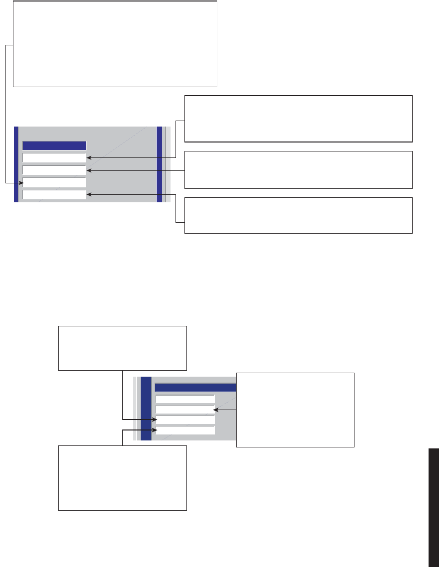
5-23
Figure 5 - 11 Troubleshooting DS3 Radio Wayside DS1 Alarms
Figure 5 - 12 Troubleshooting OC3/STM-1 Radio Wayside DS1 Alarms
DS1 Inuput Loss
DS1 XMT ALARM
DS1 AIS INSERT
DS1 RCV ALARM
DS1 ALARMS
LMW-3134
04/07/05
Loss of receive clock, buffer spills, or alarm insertion signal on
the alarmed line. May also be caused by DS1 driver failure.
Replace I/O Interface module.
Transmit hardware failure or buffer spills on alarmed line.
1. Verify quality of TX input data.
2. Replace I/O Interface module.
Loss of input signal to I/O Interface, inability to recover clock on
alarmed line, or bipolar violation detection.
1. Check presence and quality of DS1/E1 input to radio.
2. Replace I/O Interface module.
LOS has been detected at RCV Input of I/O interface
and AIS (All Ones or Zeros) is being inserted.
Check for LOS at XMT end of HOP. If not,
1. Check for upstream XMTR alarms.
Any XMTR alarms?
Yes, troubleshoot XMTR.
No, go to 2.
2. Replace alarmed DS3 I/O INTFC.
WAYSIDE DS1
DS1 Online
DS1 Output Alarm
DS1 AIS Detect
DS1 Input Alarm
LMW-5032
07/12/05
AIS detected on DS1 input to radio.
Fault is external to radio.
Check external device supplying
DS1 to radio.
Inability to recover clock or bipolar
violation detected on DS1/E1 input
to radio.
1. Check quality of DS1 input
to radio.
2. Replace I/O INTFC module.
Inability to recover clock or
bipolar violation detected on
output of radio RCVR.
1. Check XMTR end of HOP
for alarms.
2. Replace alarmed I/O INTFC
module.

5-24
5.10 ETHERNET-SPECIFIC TROUBLESHOOTING
The LEDs on the front panel of the Ethernet I/O Interface module and the alarms on the
radio USI status and alarm screen are the first indication of a fault. Troubleshoot radio
XMT and RCV alarms using the procedures in the MDR-8000 Instruction Book/Users
Manual. Troubleshoot Ethernet alarms as follows:
5.10.1 Troubleshooting Using Ethernet I/O Interface Module Front Panel Indicators
Refer to Table 5 - 3. In this analysis, troubleshoot using Table 5 - 3 to isolate the most proba-
ble cause. Replace modules or repair as directed.
Table 5 - 3 Troubleshoot Using Ethernet I/O Interface Module Indicators
LED Indication Probable Cause Corrective Action
ALM Steady
Red LED 1. Module failure 1. Replace Ethernet I/O Interface
module
WYSD
ALM Yellow LED
Lit 1. Loss of DS1 radio XMT input to
I/O Interface Check presence of DS1 input to radio.
Is DS1 Present?
Yes - Replace Ethernet I/O module.
No - Check/repair cables to customer
interface.
2. I/O Interface cannot recover
clock, or there are errors on DS1
output of radio RCVR (RCV input
to I/O Interface).
Check XMTR end of hop for alarms.
Farend XMTR alarmed?
Yes - Troubleshoot farend XMTR
No -
1. Replace local alarmed I/O Inter-
face module.
2. Replace local radio RCVR module.
3. AIS has been detected on DS1
output of radio RCVR (RCV input
to I/O Interface). RCVR fault is
not in this radio.
Check upstream XMTR/hops for
alarms.

5-25
ETH IN Green LED
Not Lit Loss of Ethernet RCV/radio XMT
signal in. Most probable causes:
1. Cable between link partner and
radio is disconnected/broken. Connect/repair cable.
2. Speed/Mode provisioning mis-
match between link partner and
radio
1. Check local Ethernet facility provi-
sioning screen.
2. Check link partner provisioning.
ETH
ALM Yellow LED
Lit Summary alarm, could be caused
by XMT or RCV Ethernet degrade Use USI to determine if degradation is
in the input or output side.
ETH
OUT Green LED
Not Lit Loss of Ethernet XMT/radio RCV
signal out. Most probable causes:
1. Loss of RF input to radio RCVR Check local RSL screen on USI. Is RSL
ok?
Yes - Check farend for Ethernet alarm.
No - Check farend XMTR output. Is
farend XMTR Out ok?
Yes - Check path, antenna,
waveguide/cabling
No - Check/replace farend XMTR.
2. Loss of Ethernet input to radio
RCVR Check farend for Ethernet alarms.
Are any alarms indicated?
Yes - Troubleshoot farend alarms
No - Check farend Ethernet status. Is
only abnormal status indicated?
Yes - Troubleshoot farend Ethernet sta-
tus.
No -
1. Replace local alarmed Ethernet I/O
Interface module.
2. Replace local RCVR module.
Table 5 - 3 Troubleshoot Using Ethernet I/O Interface Module Indicators (Cont.)
LED Indication Probable Cause Corrective Action

5-26
5.11 TMN-SPECIFIC TROUBLESHOOTING
Refer to Table 5 - 4. The red ALM LED on the front panel of the TMN Interface module
and the alarm on the radio USI status and alarm screen are the first indication of a fault.
The ALM LED on the front panel of the TMN Interface module lights for any module
fault. The LED remains lit during module reboot and also after reboot if reboot is not
completed satisfactorily.
Table 5 - 4 Troubleshooting Using TMN Interface Module Indicators
LED Indication Probable Cause Corrective Action
ALM Steady
Red 1. Module failure
2. Module reboot in progress (sev-
eral seconds to reboot)
3. Module reboot failed.
1. Replace module
2. Wait several seconds for reboot to
complete.
3. Attempt reboot.
Ethernet
1, 2,
and/or 3
Blinking
Yellow Network with too much traffic (colli-
sions occurring). Some collisions
are normal in any network.
Wait for situation to clear. If collisions
continue (severe occurrence), trouble-
shoot network.
Ethernet
1, 2,
and/or 3
Not
Steady
Green
When First
Connected
1. Cable is disconnected/ broken 1. Connect/repair cable.
2. Cable/port mismatch 2. Check application matches cable.
Straight cable instead of crossover
cable, etc.
3. Rate mismatch. Far end equip-
ment does not support 10Base/T.
3. Check far end equipment supports
10Base/T.
PPP Not
Steady
Green
When First
Connected
1. Cable is disconnected/ broken. 1. Connect/repair cable.
2. Cable/port mismatch 2. Check application matches cable.
Straight cable instead of crossover
cable, etc.
PPP Yellow Local end is receiving data but PPP
disabled locally Check local provisioning for PPP port
enabled.

5-27
Table 5 - 5 TMN Network Troubleshooting
Problem Possible Cause Possible Solution
Unusually slow communi-
cation in radio network 1. Normal network management
traffic is saturating the communi-
cations channel.
1. There may be too many radios
being managed within a single
region. Split the radio network
management into different
regions and backhaul the traffic
for each region through sepa-
rate channels.
2. Polling radios for PM data or
missed alarms too rapidly 2. Poll the radios more slowly.
3. Multiple remote software down-
loads in process 3. Download to fewer radios at a
time.
4. IP traffic other than network
management traffic being routed
through radio network
4 Configure external routers to
allow only network management
related traffic through the Man-
agement network of the radios.
Dynamic route updates (OSPF,
RIP) may attempt to reroute high
speed traffic through the TMN
network if a high speed ink fails.
Unable to operate con-
trols using SNMP To perform control operations, the
Manager must be registered as a
craft device.
Register the Manager as a craft
device. Manager registration type
can be changed as needed to type
‘ct’ to allow control operation and
then be changed back to ‘nml’ for
normal operation.
Can Read SNMP objects
but cannot Write to
SNMP objects
1. Incorrect community string 1. Use the correct community
string.
2. Insufficient SNMPv3 privileges 2. Use the correct privileges:
a) The TMN Interface supports 4
view levels. Use a SNMPv3 user
account that supports write
access to the selected SNMP
object.
b) Use the correct Authentication
mode.
c) Use the correct Privacy pass-
phrase.
3. If the TMN Interface is config-
ured for SNMPv2, the write
community string is probably
wrong.
3 Use the correct write community
string.

5-28
No traps being received
from NE 1. Manager not registered in NE to
receive traps 1. Register Manager with NE.
2. Communication failure in net-
work 2. Check network connectivity.
Check redundant network paths
and routing. Traceroute (tracert)
is useful for locating path or rout-
ing faults.
Unable to communicate
with the NE through the
radio network (unable to
‘ping’ the NE)
Possible communication path failure
or routing failure within the radio
network
Use traceroute (tracert) to help
locate for communication path or
routing problems.
Can ‘ping’ the TMN Inter-
face but cannot communi-
cate with the NE using
SNMP, or can only see a
few SNMP objects (mib-2)
in the NE.
1. Using incorrect SNMP version at
manager 1. Note the TMN card ships in
SNMPv3 mode. If SNMPv2
operation is desired, it must be
provisioned for SNMPv2 using
the TUI.
2. If using SNMPv2, using the
wrong community string. If using
SNMPv3 using wrong user-
name/passphrase pair
2. Verify community string or user-
name/passphrase.
3. A corrupt SNMPv3 security con-
figuration file may have caused
the module to revert to the previ-
ous copy of the security configu-
ration or to factory defaults.
3. Check to see if another user-
name/passphrase combination
works. Check to see if the previ-
ous passphrase works. Check
the Default username/pass-
phrase combination. It may be
necessary to re-initialize the
security configuration using the
TUI. Reprovision accounts as
required, and after the changes
have been committed, force a
reboot to copy the new security
configuration into the backup
configuration.
Table 5 - 5 TMN Network Troubleshooting (Cont.)
Problem Possible Cause Possible Solution

5-29
5.12 MODULE REPLACEMENT
Modules screwed to heat sink must be screwed securely
before power is turned on.
Units with the electrostatic-sensitive (ESS) symbol contain ESS
devices. Store these units in an antistatic container when not
in use, and anyone handling a unit should observe antistatic
precautions. Damage to the unit may result if antistatic pro-
tection is not maintained. Refer to the Special Precautions
pages in the front of the instruction book for detailed han-
dling information.
RF flex coaxial cable requires special consideration. The elec-
trical characteristics of the coax can be affected if it is acci-
dentally twisted or bent. Provide mechanical support to
prevent any weight or strain to the coax and connector
when connecting or disconnecting equipment. Loosen the
connectors at both ends of a coax section if one end must be
moved even slightly. SMA connectors should be secured fin-
gertight, and then gently tightened using a torque wrench
with a 5/16 in. head set for 7 to 9 inch-pounds. The connec-
tors should not be left fingertight.
WARNING
Possibility of
Damage
to Equipment
WARNING
Possibility of
Damage
to Equipment
WARNING
Possibility of
Damage
to Equipment

5-30
XMTR Crystals are soldered and tuned up in an oscillator
assembly board at the factory.
Modules may be removed or installed with shelf power
applied. However, exercise reasonable care to prevent contact-
ing adjacent modules. If clearances are narrow, consider set-
ting the power supply to OFF while the module is being
removed or replaced. (Before setting any switch to OFF, verify
that traffic has been protected.)
Before replacing any module, refer to Table 5 - 6 to determine the actions, other than phys-
ical replacement, required. If the module has any options (switches, subboards, etc.), refer
to the removed module so that the replacement module can be set up the same way.
Any module installed in the card cage, except those having front-panel cable connections,
can be removed by grasping the module handle(s) and pulling firmly outward. Modules
with front-panel interconnects can be removed in the same manner after disconnecting the
cable from the module being removed and moving the cable out of the way.
To install a module in the card cage, insert the module card connector edge into the appro-
priate card slot. Engage module handles in card cage and press on module handles until
they are latched and the card is fully seated. After installing a module with front-panel
interconnections, reconnect the cable(s) to the front-panel connector(s).
CAUTION
Possibility of
Service
Interruption
CAUTION
Possibility of
Service
Interruption

5-31
Table 5 - 6 Module Replacement Matrix
MODULE/UNIT REMOVAL/REPLACEMENT
PROCEDURE CHECKS/ADJUSTMENTS
PROCEDURE
AE-27AF Relay Interface No Special Procedure Required None Required
AE-37Y Controller Para. 5.14 None Required
CE-16BB Power Supply Para. 5.13 None Required
Fuse No Special Procedure Required.
Refer to Operations Section for
Location.
DX-35M DS1/E1 I/O Interface No special procedure required. None Required
DX-35N DS3 I/O Interface
(Early Versions) Para. 5.15 Para. 5.15 and Table 5 - 9
DX-35P OC3/STM-1
I/O Interface Para. 5.16 None Required
DX-35R/S ETH I/O Interface Para. 5.16 None Required
UD-35( ) Transmitter Para. 5.17 Para. 5.18, Para. 5.19,
Para. 5.20, and Para. 5.21
Crystal Oscillator Subboard Figure 5 - 15 The Crystal Oscillator Sub-
board and crystal part numbers
define this unit. The crystal is sol-
dered to the oscillator subboard
and factory tuned to the custom-
ers requirements.
Capacity Key Figure 5 - 16
UD-36( ) Receiver Para. 5.22 Para. 5.23
2
Crystal Oscillator Subboard Figure 5 - 22 The Crystal Oscillator Sub-
board and crystal part numbers
define this unit. The crystal is sol-
dered to the oscillator subboard
and factory tuned to the custom-
ers requirements.
Capacity Key Figure 5 - 23
UD-51( ) Power Amplifier
Hot-Standby Shelf
CommPak Indoor Shelf Para. 5.24
Appendix A on enclosed CD Para. 5.25
LBO/AUX/Line Interface
Hot-Standby Shelf
CommPak Indoor Shelf
Maintenance Section on
enclosed CD
Appendix H on enclosed CD No Special Procedure Required
No Special Procedure Required
RF Switch Maintenance Section on
enclosed CD No Special Procedure Required
(1)
If ATPC is in use, it must be provisioned disabled or locked high before removing controller.
(2)
Applicable to older versions of RCVR with Freq Cont on front panel.
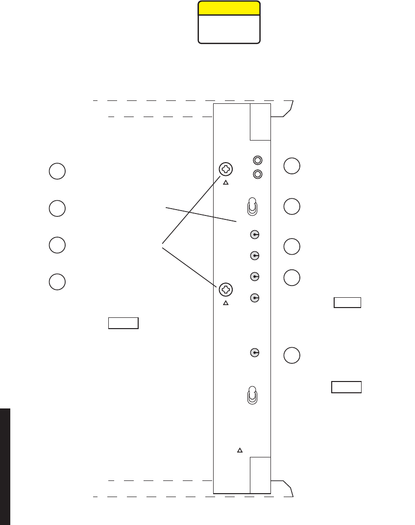
5-32
5.13 POWER SUPPLY REMOVAL AND REPLACEMENT
See Figure 5 - 13 and follow the procedure to remove and replace CE-16BB Power Supply.
Figure 5 - 13 Power Supply Removal/Installation
P/O SHELF MDR-1041
09/08/05
ALARM
P/O SHELF
OFF
NORM
ON 1
OFF 0
+10.5V
+12V
–5V
–12V
GND
TIGHTEN MOUNTING
SCREWS BEFORE
APPLYING POWER
2 PLACES
MARKED
POWER
CAUTION:
PA
ON
OFF
NOTE
If PA is not equipped, setting
PA POWER switch to ON will
turn on OFF NORM alarm.
A mismatch between software
revisions on the controller and the
replacement A-side power supply
causes a flashing controller fail
alarm when the spare power supply
is plugged in.
NOTE
NOTE
Radios have provisioning data stored on
both the controller and A-side power supply.
When provisioning is saved through
downloading, the provisioning data is stored
on both modules. If the radio is non-standby
and the A-side power supply fails, the radio
must be reprovisioned after the module is
replaced and the reprovisioned data
downloaded and saved. If the radio is
hot-standby, the provisioning data stored on
the controller is automatically copied to the
replacement A-side power supply when
p
rovisioning is saved.
REMOVE:
(Remove steps are prefixed
by the letter "R".
INSTALL:
(Install steps are prefixed
by the letter "I".
Set PA POWER switch to ON
(if equipped).
Set PA POWER switch to OFF.
Ra
Set POWER switch to OFF.
Rb
Loosen mounting screws
(if present).
Rc
Unlatch top and bottom insertion and
extraction handles and remove power
supply from shelf.
Rd
Verify joining surfaces on
power supply and heatsink
are clean. are clean.
Ia
Insert power supply in shelf and
latch top and bottom insertion
and extraction handles.
Ib
Tighten Screws (if present).
Torque screws to 19 in. lbs.
Ic
Set POWER switch to ON.
Id
Ie
This is an out-of-service procedure when on a nonstandby (unprotected) system. On a
hot-standby or frequency diversity system, switch traffic on the channel under test to
protect. Use front panel OVRD controls on AE-37( ) Controller to switch and lock
on-line opposite side XMTR, RCVR, and I/O to opposite side from failed power supply.
CAUTION
Possibility of
Service
Interruption
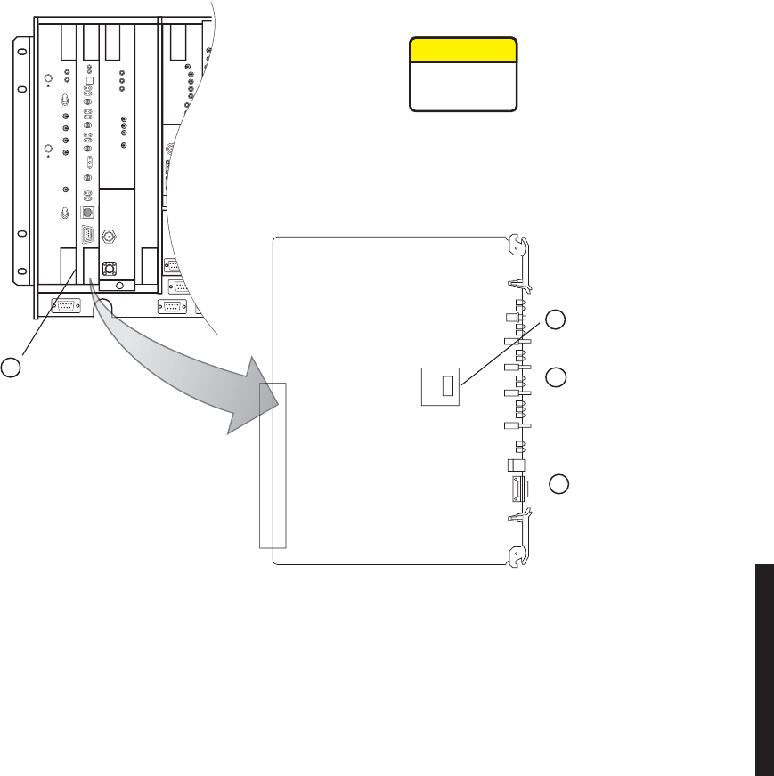
5-33
5.14 CONTROLLER REMOVAL AND REPLACEMENT
See Figure 5 - 14 and follow the procedure to remove and replace AE-37Y Controller.
Figure 5 - 14 Controller Module Installation (Sheet 1 of 4)
LBO/OC3 AUX INTFC
MDR-1042
09/08/05
J2
No – Remove controller.
Yes – On controller front panel
press and hold ACO LT/OVRD
switch in ACO LT position until
TX, RX, and I/O On Line
indicators flash. Release ACO
LT/OVRD switch and remove
controller.
Is radio OC3
or ETH?
a
Install removed
ELMC Option Key
from step 2 on
replacement
controller.
c
Install replacement
controller in shelf.
d
Remove ELMC Option
Key (if equipped).
b
CAUTION
Possibility of
Service
Interruption
This is an in service procedure, however protection switching is
disabled. If another failure occurs during the performance of
the procedure, service will be interrupted.
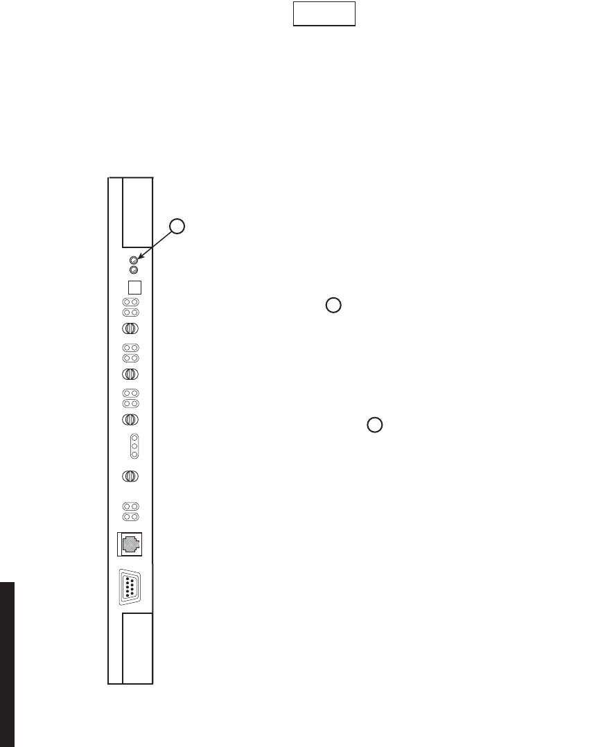
5-34
Figure 5 - 14 Controller Module Installation (Sheet 2 of 4)
e
LMW-5063
10/11/05
A
replacement controller that is loaded with the same firmware load as the controller that is
being replaced (i.e.: controller for DS3 radio is replacing a DS3 radio controller) is
automatically rebooted and provisioned to match the module it is replacing. If the replacement
controller is for a different type of radio (i.e.; controller for a DS3 radio is being used to
replace a controller in a DS1 or OC3 radio), the controller alarm will flash when the
replacement module is installed in the shelf. The flashing alarm prompts the user that the
wrong firmware is installed.
Note
Verify alarm LED is not flashing and reboot is
in progress. (reboot is indicated by all LEDs
flashing in progression.
f
h
Is controller alarm flashing?
Yes – Go to Step .
No – Is reboot in progress?
Yes – Verify Controller Version on
bottom of USI screen is latest.
Is latest version of firmware displayed?
Yes – STOP. This procedure is complete.
No – Do you want to upgrade to the latest
version?
Yes – Go to step .
No – Stop. This procedure is complete.
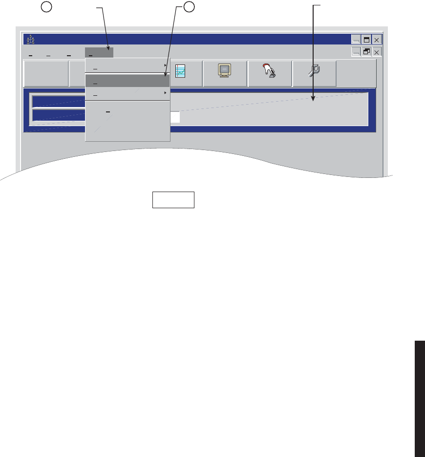
5-35
Figure 5 - 14 Controller Module Installation (Sheet 3 of 4)
Alcatel User Interface
ELMC Address
ELMC Descriptions
LOCAL MAIN
Communicating*** Prov. Hold
File View Setup Options
F6
Performance
Alarm Status
F4
Station Alarm
F7 F9
User Control
F8F5
Provisioning
Communication Options
Firmware Upgrade
Diagnostics
TDE Chip
Receive Provisioning
New Controller
MDR-1044
09/08/05
Click here.
fClick here.
gProvisioning hold
message displays.
Provisioning hold message is displayed
on all screens. The message is removed
when provisioning is saved.
Note
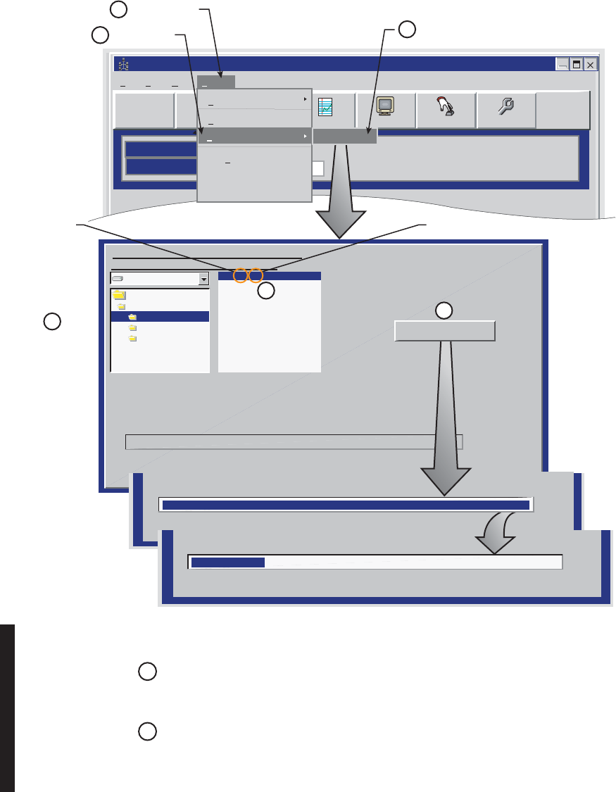
5-36
Figure 5 - 14 Controller Module Installation (Sheet 4 of 4)
Alcatel User Interface
ELMC Address
ELMC Descriptions
LOCAL MAIN
Communicating***
Prov. Hold
File View Setup Options
F6
Performance
Alarm Status
F4
Station Alarm
F7 F9
User Control
F8F5
Provisioning
Communication Options
Diagnostics
TDE Chip
Receive Provisioning
New Controller
CLICK HERE
h
CLICK HERE
j
i
Firmware Upgrade
CLICK HERE
c:
c:\
CSS00 38.DAT
The Current Select File Is:
c:\windnld\CSS00_38.DAT
Downloading at 38400 Baud
Verify Down Load
Please Select a Filename in the Following
Drive Directory before Downloading
Windnld
8000 DS1
8000 DS3
8000 OC3
css11_ 21.dat
LMW-5064-SM
10/11/05
m
k
SELECT
RADIO
PROGRESS BAR DISPLAYS
% OF DATA LOADED
VERIFY PROGRESS BAR
DISPLAYS % OF DATA VERIFIED
0%
0%
100%
100%
l
CLICK ON
LATEST FILE
(HIGHEST NUMBER
FOR RADIO TYPE)
CLICK HERE
NOTE
AFTER AUTOMATICALLY REBOOTING, THE CONTROLLER WILL START
RUNNING, PROVISIONING PREVIOUSLY STORED IN THE CONTROLLER
WILL BE LEFT UNCHANGED BY THE DOWNLOAD PROGRAM.
o
n
GO TO THE INITIAL TURNUP SECTION AND CHECK PROVISIONING/REPROVISIONING AS REQUIRED.
NOTE
AFTER PROVISIONING IS SAVED, THE CONTROLLER WILL BOOT UP
WITHIN 20 SECONDS.
STOP. THIS PROCEDURE IS COMPLETE.
Download
Start Down Load
11-DS1
12-DS3
13-OC3
21 = R2.01 = Release Version
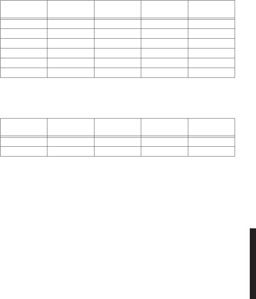
5-37
5.15 DS3 I/O INTERFACE REMOVAL AND REPLACEMENT
Follow procedure to remove and replace DX-35N DS3 I/O Interface module. Refer to
Table 5 - 7 and Table 5 - 8 for configuration functions.
aRemove I/O interface module from shelf.
bInstall I/O interface module in shelf.
cRefer to Table 5 - 9 or Table 5 - 10 and perform required procedures (if any).
dSTOP. This procedure is complete.
Table 5 - 7 1- or 3-Line I/O Interface Module
PN 3DH03169XX
Variant XX = System
Application Auto Radio DADE Auto Line DADE Front Panel
Controls
AA Linear/Ring X
AB Ring X
AG Linear/Ring X
AH Linear/Ring X X
AK Linear/Ring X X X
AM Linear/Ring X X
Note:
X indicates function is applicable.
Table 5 - 8 2-Line I/O Interface Module
PN 3DH03169XX
Variant XX = System
Application Auto Radio DADE Auto Line DADE Front Panel
Controls
AJ Linear/Ring X X X
AN Linear/Ring X X
Note:
X indicates function is applicable.

5-38
Table 5 - 9 1- or 3-Line Matrix, Valid Combinations/Procedures
I/O Interface Module
PN 3DH03169AAXX
Configuration in Shelf Position
A3, B3, Variant XX =
Radio
Configuration
Radio
DADE
(
Refer to CD
)
Line DADE
(Refer to CD)
AA AA HS, FD, SD X X
AA AB HS, FD, SD X X
AA AG HS, FD, SD X X
AA AH HS, FD, SD X X
AA AK HS, FD, SD X X
AB AB HS, FD, SD X X
AB AG HS, FD, SD X X
AB AH HS, FD, SD X X
AB AK HS, FD, SD X X
AG AG HS, FD, SD X X
AG AH HS, FD, SD X X
AG AK HS, FD, SD X X
AH AH HS, FD, SD X
AH AK HS, FD, SD X
AK AK HS, FD
AK AK SD X
AK AM HS, FD, SD
AM AM HS, FD, SD
Notes:
1. Module locations are reversible.
2. Perform procedure indicated by X for specific module and radio configuration.
Table 5 - 10 Line Matrix, Valid Combinations/Procedures
I/O Interface Module
PN3DH03169XX
Configuration In Shelf Position
A3, B3, VARIANT XX =
Radio
Configuration
Radio DADE
(Refer to CD) Line DADE
(Refer to CD)
AJ AJ HS, FD, SD X X
AJ AL HS, FD, SD X X
AL AL HS, FD
AL AL SD X
AL AN HS, FD, SD
AN AN HS, FD, SD
NOTES:
1. Module locations are reversible.
2. Perform procedure indicated by X for specific module and radio configuration.

5-39
5.16 OC3/STM-1/ETH I/O INTERFACE REMOVAL AND REPLACEMENT
Use this procedure to remove and replace DX-35P OC3/STM-1 or DX-35R/S ETH I/O
Interface module.
aIf radio is protected (hot-standby, space diversity, or frequency diversity,
use front panel
OVRD
controls on AE-37( ) Controller to lock on-line
XMTR, RCVR, and I/O (opposite side from failed I/O) on line.
bOn front panel of controller module, press and hold
ACO LT/OVRD
switch
in
ACO LT
(lamp test) position until
TX, RX
, and
I/O On LINE
LEDs on
front of controller flash (approximately 5 seconds wait).
cRelease
ACO LT/OVRD
switch.
dDisconnect cables.
eRemove I/O Interface module from shelf.
fInstall replacement I/O Interface module in shelf.
gConnect cables.
hOn AE-37( ) Controller, toggle OVRD switch to disable override (unlocks
on-line XMTR and restores automatic switching functions).
iSTOP. This procedure is complete.

5-40
5.17 XMTR REMOVAL AND REPLACEMENT
Use this procedure to remove and replace the UD-35( ) XMTR and/or Capacity Key and
Crystal Oscillator Subboards on the XMTR.
Spare XMTRs and XMTRs repaired at the factory normally do not con-
tain Crystal Oscillator Subboards or Capacity Keys. The user must retain
the crystal Oscillator Subboard and the Capacity Key from the module
being replaced before sending the module back to the factory for repair.
aOn power supply, on same side as failed XMTR, set PA ON/OFF switch to
OFF (if shelf is equipped with PA on that side).
bOn XMTR module, disconnect cable from RF OUT connector.
cRemove XMTR module from card cage.
dOn XMTR module being replaced, remove XMTR crystal oscillator
subboard. See Figure 5 - 15. Retain for installation on replacement
module.
eOn XMTR module being replaced, remove XMTR capacity key. See
Figure 5 - 16. Retain for installation on replacement module.
fOn replacement XMTR module, install XMTR crystal oscillator subboard.
See Figure 5 - 15.
g
On replacement XMTR module, install XMTR capacity key. See Figure 5 - 16.
hReconnect cable to RF OUT connector.
iInstall replacement XMTR module in card cage.
Note

5-41
jPerform XMT Crystal Oscillator Frequency Checks and Adjustment
procedure. Refer to Para. 5.18.
kOn power supply, set PA ON/OFF switch to ON (if turned off in Step a).
Output level calibration is required for the last amplification stage in
the chain of XMT amplifiers leading to the antenna, only. If the radio is
equipped with a PA and a transmitter fails, the replacement transmit-
ter must be adjusted to return the radio to the original PA output
power. It is not necessary to calibrate the transmitter.
lIs radio equipped with optional PA?
If no, Perform XMTR Output Level Calibration (No PA) procedure. Refer to
Para. 5.21.
If yes, restore PA output level. See applicable Figure 5 - 17 or Figure 5 - 18 for pro-
cedure.
mPerform one of the following XMTR Carrier Null Adjustment procedures:
In-Service XMTR Carrier Null Adjustment Using spectrum
Analyzer, Para. 5.20
XMTR Carrier Null Adjustment Using Spectrum Analyzer,
(Refer to CD).
XMTR Carrier Null Adjustment Using DVM, (Refer to CD).
nSTOP. This procedure is complete.
Note
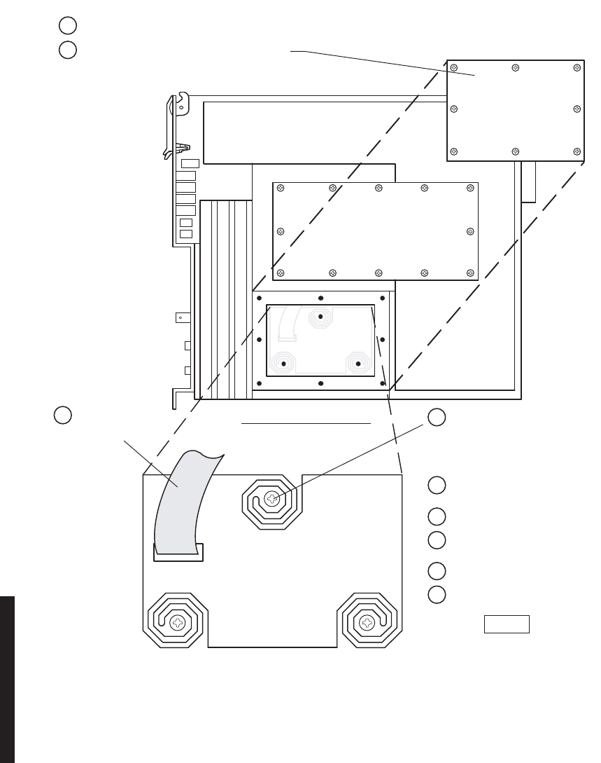
5-42
Figure 5 - 15 XMTR Crystal Oscillator Subboard Removal/Installation
CRYSTAL OSC
SUBBOARD
J8
XMTR–RIGHT SIDE VIEW
MDR-1021
09/08/05
Ensure board edge does not make
contact with chassis wall.
Note
Remove:
b
Remove 8 screws from Crystal Ocsillator
Subboard cover, and remove cover.
dRemove 3 mounting screws,
and remove Crystal Oscillator
Subboard.
cDisconnect ribbon
cable from J8.
aRemove transmitter from card cage.
Install:
ePlace Crystal Oscillator
Subboard in mounting cavity.
gConnect ribbon cable to
connector J8.
hInstall cover with 8 screws.
iInstall XMTR in card cage.
fInstall 3 mounting screws.
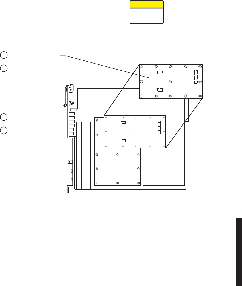
5-43
Figure 5 - 16 XMTR Capacity Key Removal/Installation
XMTR-RIGHT SIDE VIEW
LMW-6016-SM
09/08/05
Remove:
bRemove 13 screws
from Capacity Key and
remove Capacity Key.
aRemove transmitter
from card cage.
Install:
dInstall 13 screws.
cInstall Capacity Key on
three connectors.
This is an out-of-service procedure when on a
nonstandby (unprotected) system. On a hot-standby
or frequency diversity system, switch traffic on the
channel under test to protect.
CAUTION
Possibility of
Service
Interruption
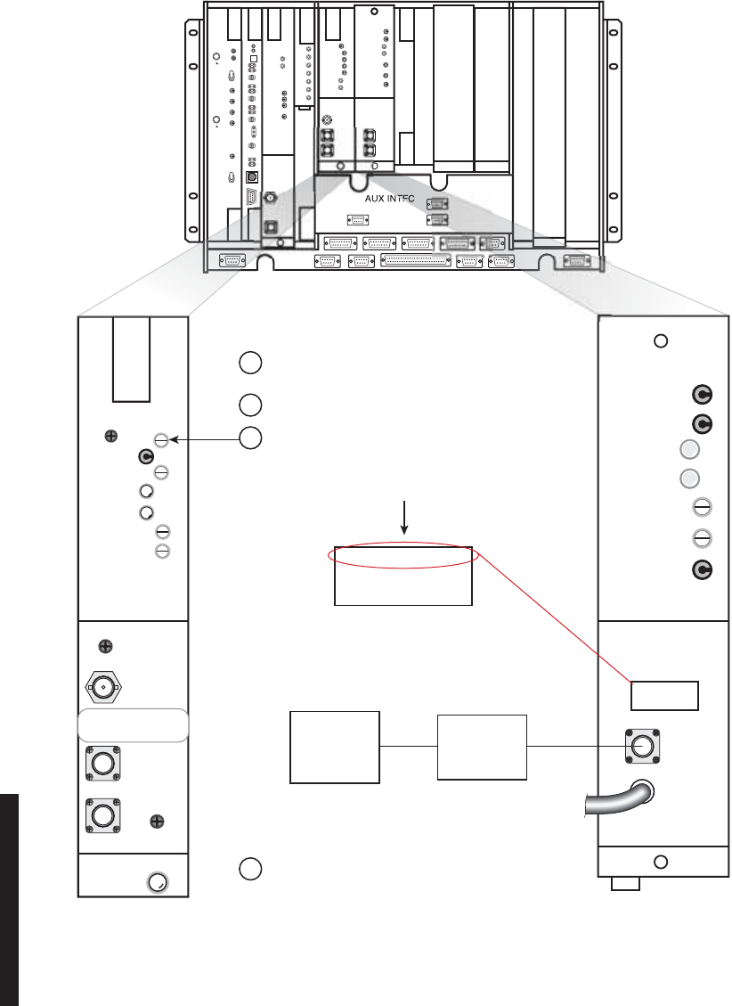
5-44
Figure 5 - 17 Restoring PA Output Power Using Power Meter
PWR MON
XMT PWR
ALM
ON LINE
I CARR NULL
XMT LVL
ADJ
FREQ CONT
Q CARR NULL
TRANSMITTER
RF
OUT
XTAL
MON
RF
MON
READ [X.X dBm]
FOR [XX.X dBm]
AT TOP OF RACK
READ X.X dBm
FOR XX.X dBm
AT TOP OF RACK
DC
MON
GND
10.5V DC
PWR ALM
TEMP ALM
DC MON ADJ
PWR ALM ADJ
POWER AMPLIFIER
RF
IN
RF
MON
READ X.X dBm
FOR XX.X dBm
AT TOP OF RACK
POWER
SENSOR
50 OHM
POWER
METER
NTFC
MDR-1173
09/08/05
aConnect power meter with 50 OHM power
sensor to RF MON connector on PA.
c
While monitoring power meter, adjust
XMT
LVL ADJ control on XMTR for READ
X.X dBm level on PA label.
This returns PA
output level original level.
bMeasure RF monitor level on power meter.
d
Disconnect test equipment.
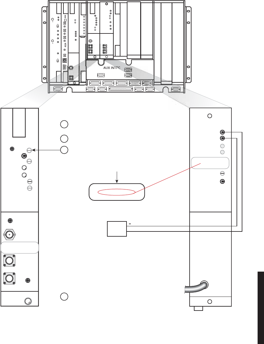
5-45
Figure 5 - 18 Restoring PA Output Power Using DVM
aConnect DVM to DC MON (+) test point and
GND on
PA.
c
While monitoring voltage on DVM, adjust XMT
LVL ADJ control on XMTR for READ (X.X Vdc)
voltage on PA label. This returns PA output
level to original level.
bMeasure DC monitor level on DVM.
d
Disconnect test equipment.
PWR MON
XMT PWR
ALM
ON LINE
I CARR NULL
XMT LVL
ADJ
FREQ CONT
Q CARR NULL
TRANSMITTER
RF
OUT
XTAL
MON
RF
MON
READ [X.X dBm]
FOR [XX.X dBm]
AT TOP OF RACK
DC MON
GND
10.5V DC
PWR ALM
TEMP ALM
DC MON ADJ
PWR ALM ADJ
POWER AMPLIFIER
RF
IN
DVM
+
DC MONITOR CALIBRATION
READ [X.X Vdc]
FOR [XX.X dBm]
DC MONITOR CALIBRATION
READ [X.X Vdc]
FOR [XX.X dBm]
TFC
MDR-1174
09/08/05
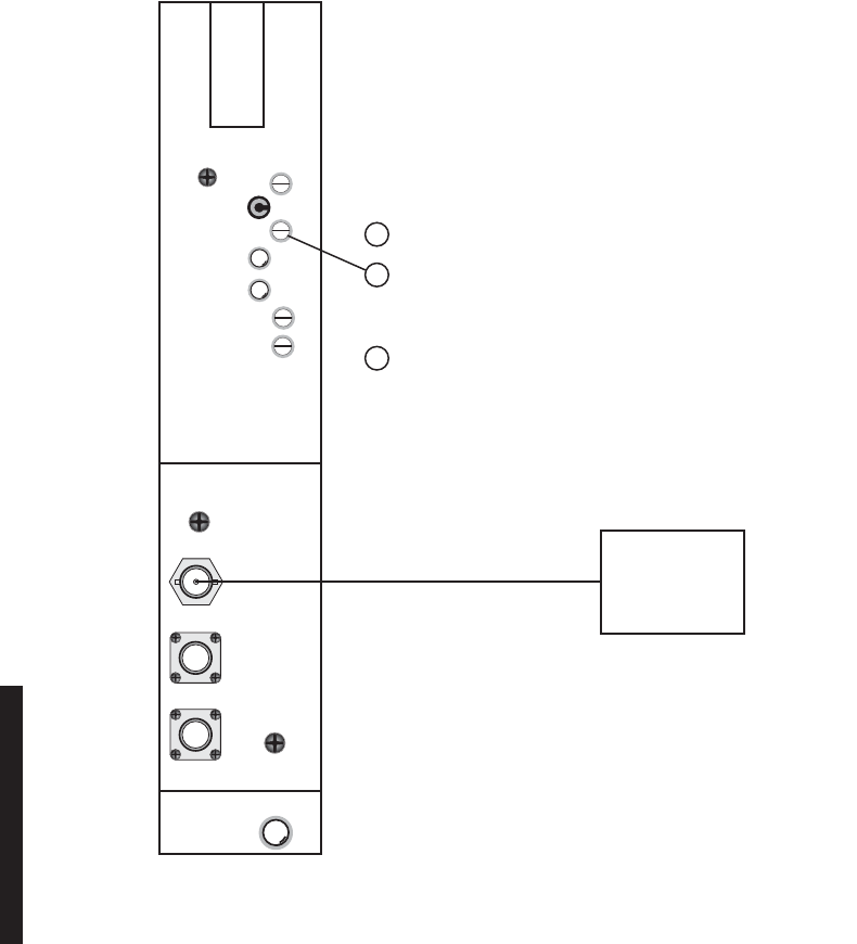
5-46
5.18 XMT CRYSTAL OSCILLATOR FREQUENCY CORRECTION
PURPOSE
See Figure 5 - 19 and follow the procedure to correct the transmit frequency of the crystal
oscillator on the UD-35() Transmitter module.
Allow a 1-hour warm-up period for radio and test equipment before starting applicable
tests or improper frequency adjustment can result. If waiting for initial alignment is
impractical, it may be performed after a warm-up period of 5 minutes minimum; however,
crystal frequency should be rechecked after full warmup.
Figure 5 - 19 XMT Crystal Oscillator Frequency Check
PWR MON
XMT PWR
ALM
ON LINE
I CARR NULL
XMT LVL
ADJ
FREQ CONT
Q CARR NULL
TRANSMITTER
RF
OUT
XTAL
MON
RF
MON
FREQ
COUNTER
Connect Frequency Counter to XTAL MON connector.
a
Verify XMT LO frequency indicated on Frequency Counter
is crystal reference frequency ± 3 parts per million. If not,
adjust Freq Cont.
b
Check/adjust Carrier Null using Spectrum Analyzer
(Paragraph 5-22 or 5-23) or DVM (Paragraph 5-24).
c
MDR-1053
02/09/07
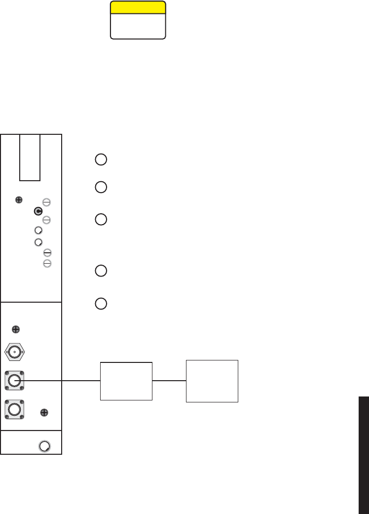
5-47
5.19 XMTR OUTPUT LEVEL CHECK (NO PA)
See Figure 5 - 20 and follow the procedure to check the RF output of the UD-35( ) Transmit-
ter in radio configuration that is not equipped with the optional PA.
This is an out-of-service procedure when on a nonstandby
(unprotected) system. On a hot-standby or frequency diversity
system, switch traffic on the channel under test off line.
Figure 5 - 20 XMTR Output Level Check (No PA)
CAUTION
Possibility of
Service
Interruption
MDR-1145
02/08/07
d If ATPC was enabled prior to performing
this procedure, re-enable.
e Stop. This procedure is complete.
b Connect Power Meter with 50 OHM
Power Sensor to RF MON Connector.
a
If ATPC is enabled, disable (XMTR will
go to high power).
c
Level on Power Meter should be same
as on label ± 0.5 dB (0 dBm nominal).
If not, adjust level using procedure in
Para. 5.25.
PWR MON
XMT PWR
ALM
ON LINE
I CARR NULL
XMT LVL
ADJ
FREQ CONT
Q CARR NULL
TRANSMITTER
RF
OUT
XTAL
MON
RF
MON
MEDIUM
POWER
SENSOR
POWER
METER

5-48
5.20 IN-SERVICE XMTR CARRIER NULL ADJUSTMENT USING SPECTRUM ANALYZER
See the following figures and follow the procedure to adjust carrier null on the UD-35A()
Transmitter, in service. For out-of-service carrier null procedures, refer to CD.
Carrier leakage can be nulled in the MDR-8000 using any one of three
methods. Method 1 (the preferred method) uses a spectrum analyzer to
determine if carrier leakage is present while a modulated signal is
being transmitted (in service) and then nulling any carrier present.
Methods 2 and 3 require that modulation be removed and the carrier is
nulled while the transmitter is out of service. Method 2 uses a DVM to
measure carrier leakage. Method 3 uses a spectrum analyzer.
Using the spectrum analyzer Span controls, reduce the frequency span until the
Resolution Bandwidth (
Res BW
) reaches the value defined as the
Res BW for measuring
carrier
. At this
Res BW
, observe the spectrum trace for a carrier signal. If a carrier signal,
rising above the spectrum floor, 3 dB or more is visible, use the procedure to null the
carrier. If no carrier is visible, the carrier is sufficiently nulled.
Ensure that the radio, and specifically the transmitter unit, is
allowed to warm up for at least one hour operating in the
radio before performing carrier null adjustments.
Note
CAUTION
Possibility of
Service
Interruption
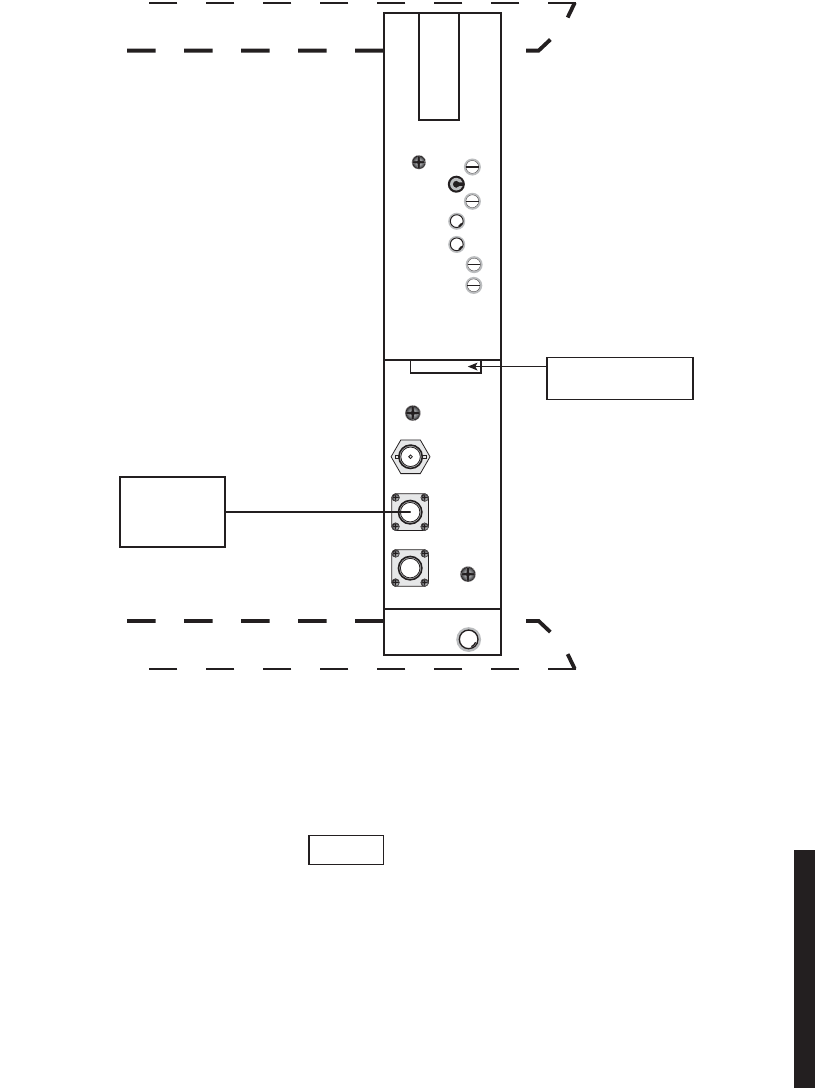
5-49
cCarefully adjust the spectrum analyzer to center the transmitter
spectrum.
As the spectrum analyzer’s frequency span is reduced and the flat top of
the spectrum fills the spectrum analyzer display, it is extremely impor-
tant to keep the spectrum display (with carrier signal if any) centered
so that the carrier signal (if any) will remain visible as the span is
reduced.
b. SET SPECTRUM ANALYZER CONTROLS.
CONTROL SETTING
INPUT ATTEN (dB) 10 dB
CENTER FREQ CHAN FREQ
(SEE FREQ LABEL
ON XMTR OR PA).
FREQ SPAN VALUE APPROXIMATELY
TWICE THE WIDTH OF
THE RF CHANNEL
BANDWIDTH
RESOLUTION BW AUTO
VIDEO BW AUTO
REFERENCE LEVEL O dBm
SWEEP TIME AUTO
AMPLITUDE SCALE 10 dB/DIV
a. CONNECT SPECTRUM ANALYZER
TO RF MON CONNECTOR.
PWR MON
XMT PWR
ALM
ON LINE
I CARR NULL
XMT LVL
ADJ
FREQ CONT
Q CARR NULL
TRANSMITTER
RF
OUT
XTAL
MON
RF
MON
MDR-1209
10/11/05
FREQ LABEL
PO SHELF
PO SHELF
SPECTRUM
ANALYZER
CHAN FREQ MHz
XTL FREQ MHz
Note

5-50
dReduce the frequency span on the spectrum analyzer display while
keeping the spectrum centered on the spectrum analyzer display.
eContinue to reduce the spectrum analyzer span while observing the
Res
BW
field in the bottom left corner of the spectrum analyzer display.
fContinue reducing the frequency span until the correct
Res BW
for
measuring carrier for the Radio Capacity/Modulation is displayed. Refer
to the following table for the
Res BW
for measuring carrier required for
the radio under test.
Carrier Threshold Resolution Bandwidth
Radio Capacity/Modulation Res BW For Measuring Carrier Res BW For Nulling Carrier
OC3/128 TCM 30 kHz 1 kHz
1 STS-1/128 TCM 10 kHz 300 Hz
3 DS3/64 QAM 100 kHz 3 kHz
2 DS3/32 TCM 100 kHz 3 kHz
1 DS3/64 QAM 30 kHz 1 kHz
16 DS1/32 TCM 10 kHz 1 kHz
16 DS1/128 TCM 3 kHz 100 Hz
12 DS1/32 TCM 10 kHz 300 Hz
12 DS1/128 TCM 3 kHz 100 Hz
8 DS1/32 TCM 10 kHz 300 Hz
8 DS1/128 TCM 1 kHz 100 Hz
4 DS1/32 TCM 3 kHz 100 Hz
4 DS1/128 TCM 1 kHz 30 Hz
2 DS1/32 TCM 3 kHz 100 Hz
2 DS1/128 TCM 300 Hz 30 Hz

5-51
Adjustment of the carrier signal for minimum amplitude is
critical. Do not attempt to null the carrier signal until the
correct Res BW is reached. Incorrect adjustment can result in
loss of traffic due to slow RCVR lock.
gObserve the display at the correct
Res BW
for measuring carrier for a
carrier signal rising above the floor of the spectrum. Is a carrier signal
rising 3 dB or more above the spectrum visible?
No. STOP. This procedure is complete. Carrier is nulled to an
acceptable level.
Yes.
1) Continue to reduce the frequency span until the spectrum
analyzer shows a Res BW equal to or lower than the
Res
BW For Nulling Carrier
value shown in the table.
2) Alternately adjust the I Carr and Q Carr controls on the
XMTR module for minimum carrier amplitude. Refer to
the following typical scenario for adjustment tips/prob-
lems.
TYPICAL ADJUSTMENT SCENARIO
Refer to the following step-by-step adjustment of 3 DS3/64 QAM radio. In this scenario,
carrier null adjustment is required due to slow RCVR lockup following a deep fade. The
Res BW
for nulling carrier for the 3 DS3/64 QAM radio is 3 kHz as listed in the table.
CAUTION
Possibility of
Service
Interruption
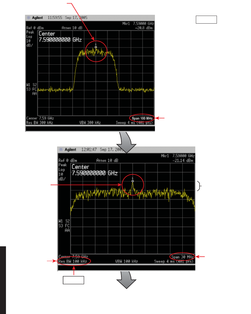
5-52
a. Center carrier
on screen.
b. Reduce Span
to 30 mHz.
d. Reduce Span
to 5 mHz.
c. Center carrier
on screen.
Res BW for
measuring carrier
10 dB above
spectrum floor
Note
Res BW automatically decreases
as Span decreases.
MDR-1216
09/20/05
Note
It is extremely important to keep the
carrier signal centered in the display
so that the carrier will become visible
as the span is reduced.
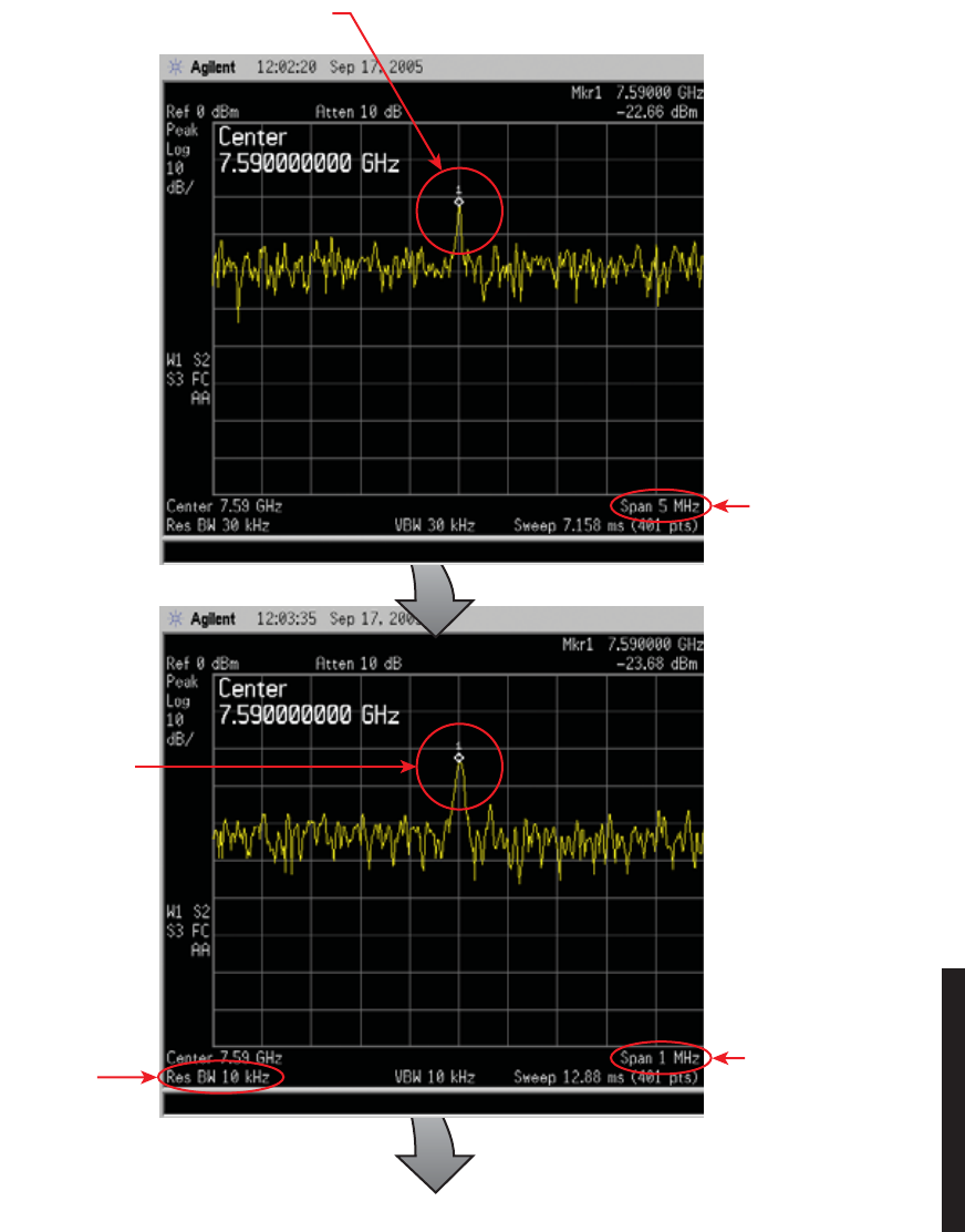
5-53
e. Center carrier
on screen.
f. Reduce Span
to 1 mHz.
i. Reduce Span
to 500 kHz.
h. Observe
Res BW
g. Center carrier
on screen.
MDR-1217
09/20/05
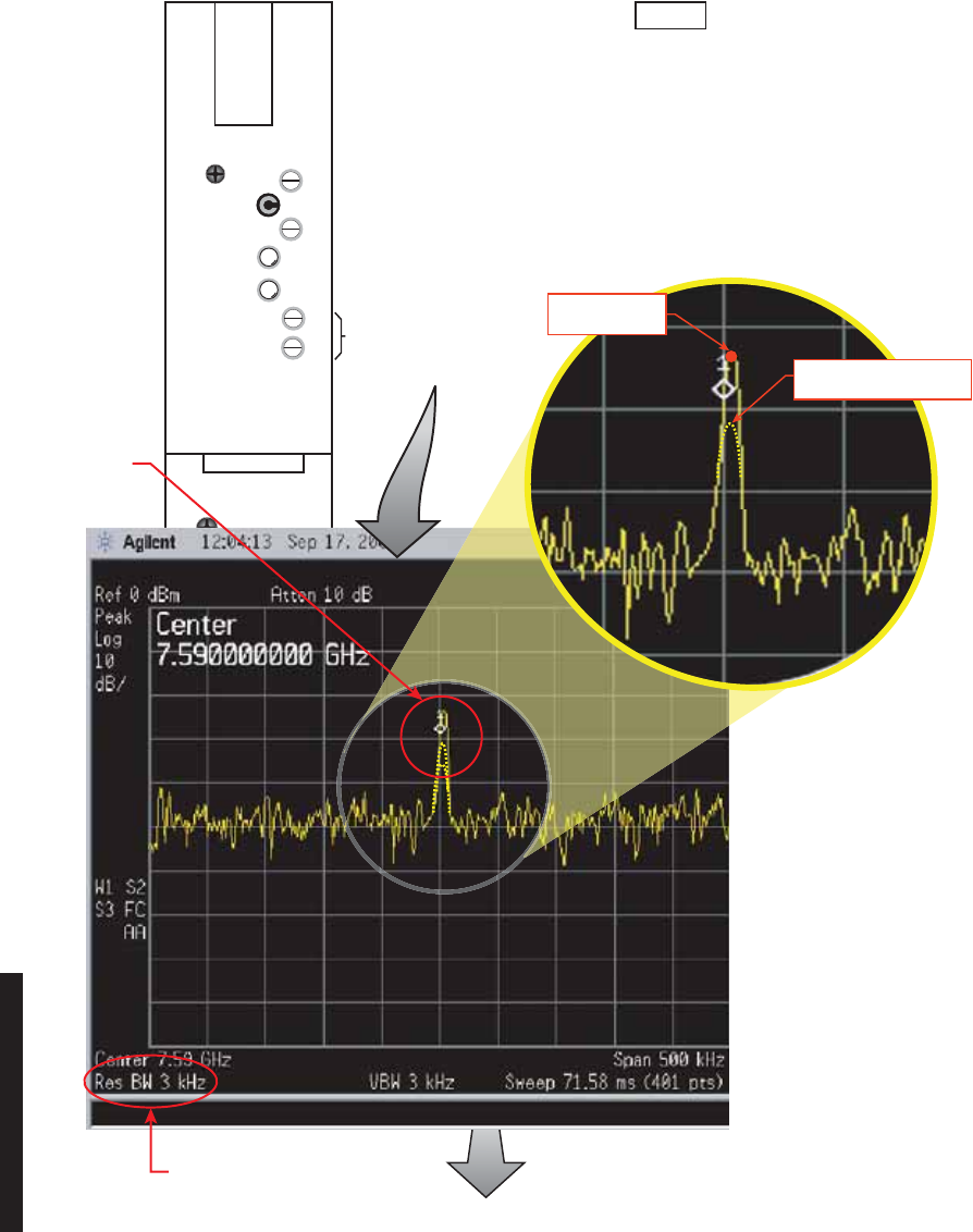
5-54
PWR MON
XMT PWR
ALM
ON LINE
I CARR NULL
XMT LVL
ADJ
FREQ CONT
Q CARR NULL
TRANSMITTER
RF
OUT
XTAL
MON
RF
MON
MDR-1211
09/20/05
k. Alternately adjust I & Q
Carr Null controls for
minimum carrier amplitude. Dashed lines are used to
show changes in amplitude.
Carrier peak at
start of procedure
Note
You must watch the trace carefully on the spectrum analyzer when adjusting
the I and Q carrier controls on the XMTR module. the I and Q carrier controls
are interactive and the slightest change on one control causes a change on the
other. You must alternate between controls until carrier null is obtained. The
direction to turn the controls is not defined. If for example, the carrier level is
dropping as you are turning the I CARR control counterclockwise, continue to
turn counterclockwise until the carrier level on the trace stops dropping and
then starts to go up. Then turn the Q CARR control counterclockwise or
clockwise until downward movement is seen on the trace and continue to turn
in that direction. Watch for the slightest change in direction and then move to
the other control.
j
. Center
carrier
on screen.
Res BW For Nulling Carrier
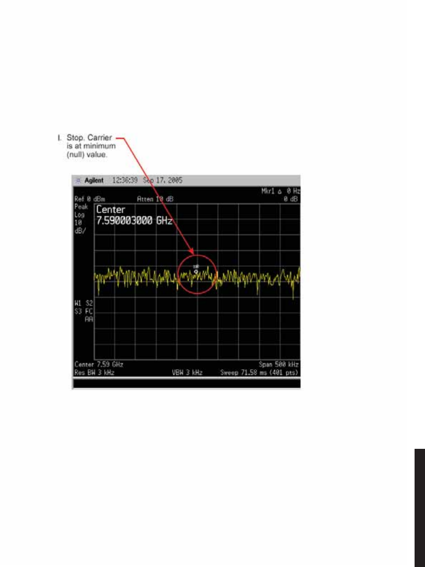
5-55
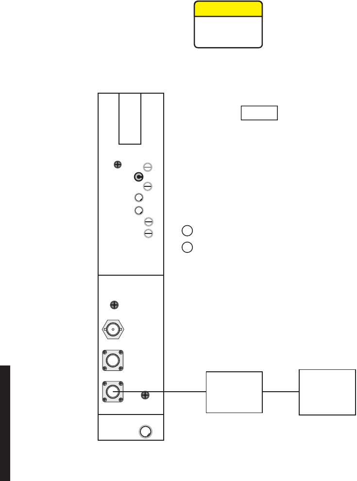
5-56
5.21 XMTR OUTPUT LEVEL CALIBRATION
See Figure 5 - 21 and follow the procedure to check, and if necessary adjust, the RF output
of the UD-35() Transmitter in radio configuration that is not equipped with the optional
PA.
Figure 5 - 21 XMTR Output Level Calibration (Sheet 1 of 5)
MDR-1059
09/08/05
PWR MON
XMT PWR
ALM
ON LINE
I CARR NULL
XMT LVL
ADJ
FREQ CONT
Q CARR NULL
TRANSMITTER
RF
OUT
XTAL
MON
RF
MON
MEDIUM
POWER
SENSOR
POWER
METER
Disconnect cable from RF OUT connector.
a
Connect power meter with medium power
sensor to RF OUT connector.
b
Note
If ATPC is enabled, disable (XMTR will
go to high power).
CAUTION
Possibility of
Service
Interruption
This is an out-of-service procedure when on a nonstandby
(unprotected) system. On a hot-standby or frequency diversity
system, switch traffic on the channel under test to protect.
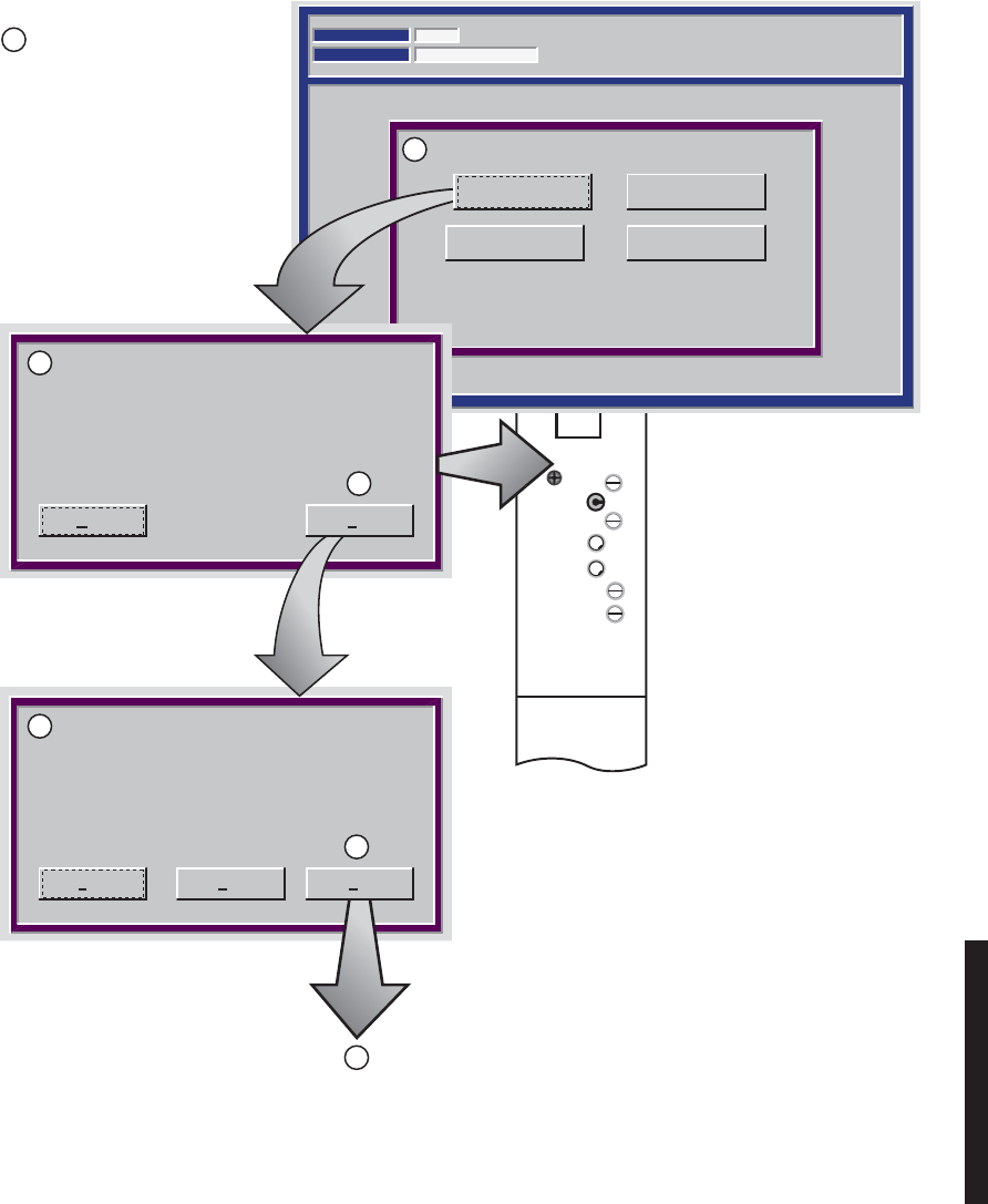
5-57
Figure 5 - 21 XMTR Output Level Calibration (Sheet 2 of 5)
PWR MON
XMT PWR
ALM
ON LINE
I CARR NULL
XMT LVL
ADJ
FREQ CONT
Q CARR NULL
TRANSMITTER
TRANSMIT POWER CALIBRATION
Communicating*
ELMC Address:
Description: MDR-8000
RACK6
12:17:01 PM
10-May-99
CLICK CALIBRATE A OR B SIDE
Carrier Null A Carrier Null B
Calibrate B-side
Set your Tx Level to 10 dB below nominal
HIGH power using the (XMT LVL ADJ)
potentiometer on your TRANSMITTER
module. After this is done, click Next.
Set your Tx Level to nominal HIGH power
using the (XMT LVL ADJ) potentiometer on
your TRANSMITTER module. After this is done,
click NEXT.
Calibrate A Side
MDR-1060
09/08/05
Abort Next
Abort NextBack
Example:
Expected output level at top of stack = 14 dBm.
Label on diplexer filter/XMT filter shows insertion loss is 2dB.
Nominal high power out of XMTR = 16 dBm
(14 dBm + 2 dBm = 16 dBm).
Set nominal low power level for 6 dBm
(10 dB down from 16 dBm).
Determine XMTR nominal
high and low output level:
c
XMTR nominal high output level
= level at top of stack + insertion
loss of diplexer filter/XMT filter
(marked on label on filter.
XMTR nominal low output level
= XMTR nominal high output
level – 10 dB.
Proceed to
Sheet 3
d
e
f
g
h
i
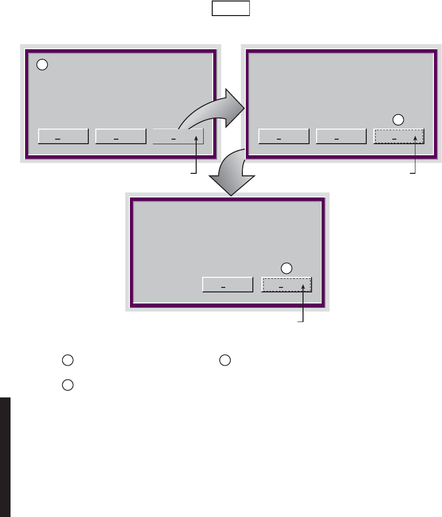
5-58
Figure 5 - 21 XMTR Output Level Calibration (Sheet 3 of 5)
MDR-6061
09/08/05
Back Finish
Abort Back NextAbort Back Next
Save the calibrated values. Click next Storing calibration data, please wait...
Successfully stored calibration data
Click Finish.
Calibration is
complete.
Click Next. Click Next.
i
j
k
Disconnect power meter and sensor
from RF OUT connector.
l
Reconnect cable to RF OUT
connector.
m
Observe RF MON label on XMTR
front panel. On label, is the measured
READ level in dBm or Vdc?
n
If labeled READ X.X dBm, go to step o.
If labeled READ X.X Vdc, go to step s.
Note
Ensure ATPC is disabled.
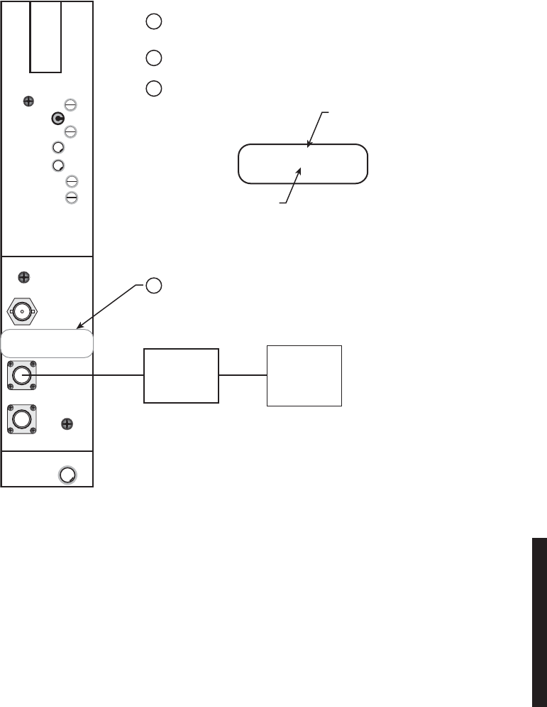
5-59
Figure 5 - 21 XMTR Output Level Calibration (Sheet 4 of 5)
MDR-1062
09/08/05
PWR MON
XMT PWR
ALM
ON LINE
I CARR NULL
XMT LVL
ADJ
FREQ CONT
Q CARR NULL
TRANSMITTER
RF
OUT
XTAL
MON
RF
MON
POWER
SENSOR
50 OHM
POWER
METER
READ [X.X dBm]
FOR [XX.X dBm]
AT TOP OF RACK
READ [X.X dBm]
FOR [XX.X dBm]
AT TOP OF RACK
EXPECTED OUTPUT LEVEL
AT TOP OF STACK
(REFER TO FIGURE 9-35 STEP a).
MEASURED LEVEL
(STEP b).
Connect Power Meter with 50 OHM Power
Sensor to RF MON connector.
o
Measure RF Monitor Level on Power Meter.
p
Make new label for RF MON.
q
Attach new label.
r
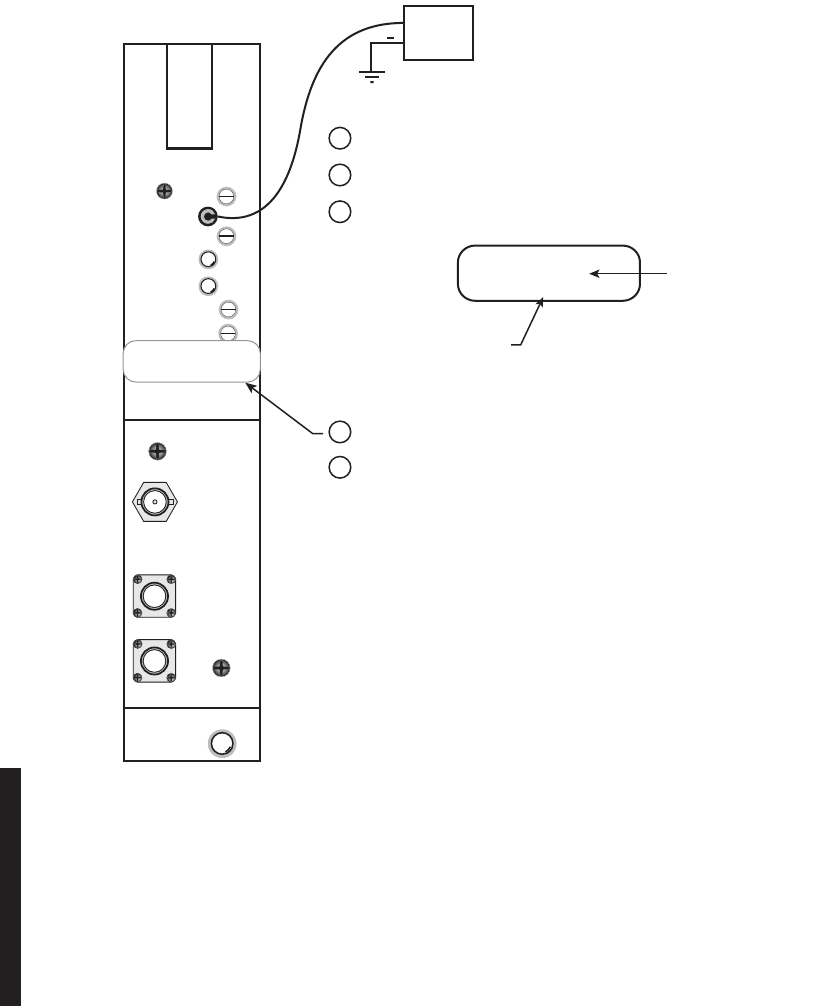
5-60
Figure 5 - 21 XMTR Output Level Calibration (Sheet 5 of 5)
MDR-1063
09/08/05
PWR MON
XMT PWR
ALM
ON LINE
I CARR NULL
XMT LVL
ADJ
FREQ CONT
Q CARR NULL
TRANSMITTER
RF
OUT
XTAL
MON
RF
MON
DC MONITOR CALIBRATION
READ [X.X Vdc]
FOR [XX.X dBm]
DVM
+
DC MONITOR CALIBRATION
READ [X.X Vdc]
FOR [XX.X dBm]
EXPECTED OUTPUT LEVEL
AT TOP OF STACK
MEASURED LEVEL
(STEP b).
Connect DVM to PWR MON test point.
s
Re-check carrier null.
w
Measure voltage on DVM.
t
Make new label.
u
Attach new label.
v

5-61
5.22 RCVR REMOVAL AND REPLACEMENT
Use this procedure to remove and replace UD-36() RCVR.
This is an out-of-service procedure when on a nonstandby
(unprotected) system. On a hot-standby, space diversity, or fre-
quency diversity system, switch traffic on the channel under
test to protect. Use front panel OVRD controls on AE-37() Con-
troller to switch and lock opposite side RCVR (opposite side
from failed RCVR) on line.
aOn RCVR module, disconnect cable from RF In connector.
bRemove RCVR module from card cage.
cOn RCVR module being replaced, remove RCVR Crystal Oscillator
Subboard. See Figure 5 - 22. Retain for installation on replacement
module.
dOn RCVR module being replaced, remove RCVR Capacity Key. See Figure 5 - 23. Retain for installation on replacement module.
eOn replacement RCVR module, install RCVR Crystal Oscillator
Subboard. See Figure 5 - 22.
fOn replacement RCVR module, install RCVR Capacity Key. See Figure 5 - 23.
gInstall replacement RCVR module in card cage.
hIs RCVR equipped with front panel Freq Cont.?
If yes, go to step i
If no, go to step j.
iPerform RCV Crystal Oscillator Frequency checks and adjustment
procedure. Refer to Para. 5.23.
jStop. This procedure is complete.
CAUTION
Possibility of
Service
Interruption
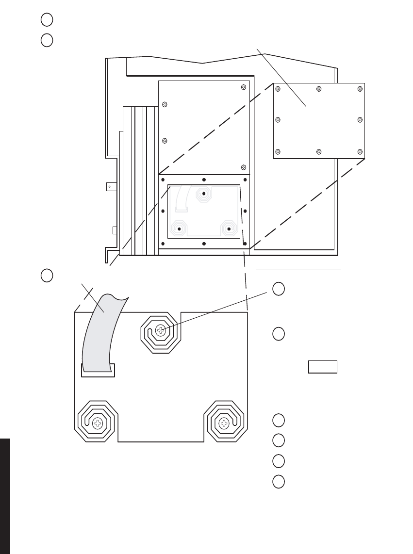
5-62
Figure 5 - 22 RCVR Crystal Oscillator Subboard Removal/Installation
CRYSTAL OSC
SUBBOARD
J8
RCVR–RIGHT SIDE VIEW
MDR-1064
10/04/04
Ensure board edge does not make
contact with chassis wall.
Note
Remove:
aRemove Receiver from card cage.
Install:
ePlace Crystal OSC Subboard in
mounting cavity.
f
Install 3 mounting screws.
h
Install cover with 8 screws.
i
Install Receiver in card cage.
g
Connect ribbon cable to Connector J8.
bRemove 8 screws from Crystal OSC Subboard cover, and remove cover.
c
Disconnect ribbon cable from J8.
d
Remove 3 mounting screws, and
remove Crystal OSC Subboard.
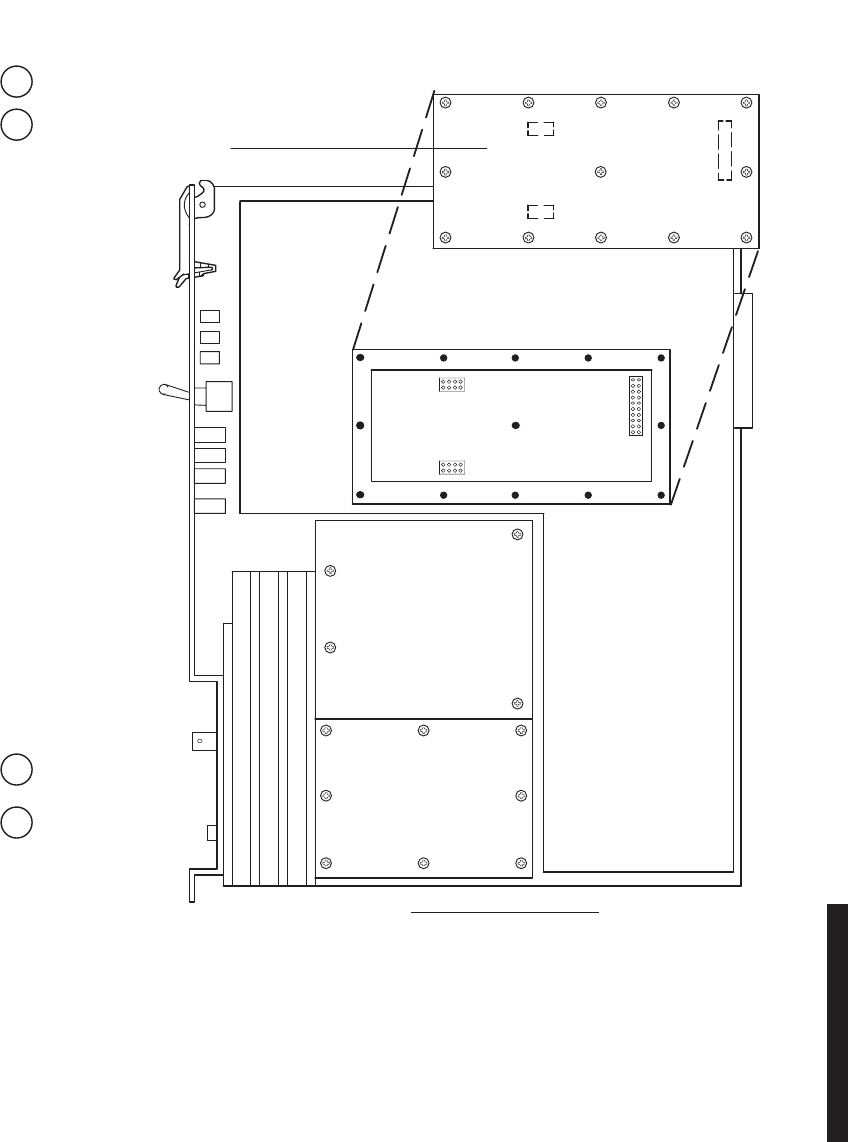
5-63
Figure 5 - 23 RCVR Capacity Key Removal/Installation
MDR-1065
10/04/04
REMOVE:
(Remove steps are prefixed
by the letter "R".
INSTALL:
(Install steps are prefixed
by the letter "I".
Remove Receiver from card cage.
R1
Remove 13 screws from Capacity Key,
and remove Capacity Key.
R2
Install Capacity Key
on 3 connectors.
I1
Install 13 screws.
I2
RCVR – RIGHT SIDE VIEW
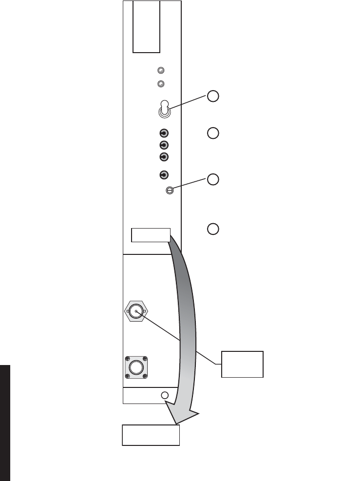
5-64
5.23 RCV CRYSTAL OSCILLATOR FREQUENCY CORRECTION
See Figure 5 - 24 and follow the procedure to correct the receive frequency of the crystal
oscillator on older versions of the UD-36 ( ) receiver module.
Allow a 1-hour warm-up period for radio and test equipment before starting procedure or
improper frequency adjustment can result.
Figure 5 - 24 RCV LO Adjustment
a. SET TO PED.
CHAN ALM
EYE
CLOSURE
AFC MON
EYE MON
RSL MON
GND
FREQ
CONT
RECEIVER
XTAL
MON
RF
IN
LMW-6090-SM
05/27/02
c. VERIFY CRYSTAL FREQ IS SAME AS
LABEL. IF NOT, ADJUST FREQ CONT
FOR CRYSTAL FREQ.
d. SET AFC PED/NORM
SWITCH TO NORM.
b. CONNECT FREQ COUNTER TO
XTAL MON CONNECTOR.
10.650 GHz
142.0000 MHz
LABEL
PED
AFC
NORM
RF FREQ
CRYSTAL FREQ
FREQ
COUNTER

5-65
5.24 PA REMOVAL AND REPLACEMENT
See Figure 5 - 25 and follow the procedure to remove and replace UD-51() PA.
This is an out-of-service procedure when on a nonstandby
(unprotected) system. On a hot-standby or frequency diversity
system, switch traffic on the channel under test to protect. Use
front panel OVRD controls on AE-37() Controller to lock on-
line XMTR (opposite side from failed XMTR) on line.
To prevent monitor point errors, use caution to ensure that
the front panel removed from the PA is replaced on that
same PA. No two monitor point levels labeled on PAs are the
same. Erroneous output levels can result from installing the
wrong front panel and calibrating the PA to the level labeled
on that front panel.
CAUTION
Possibility of
Service
Interruption
WARNING
Possibility of
Damage
to Equipment
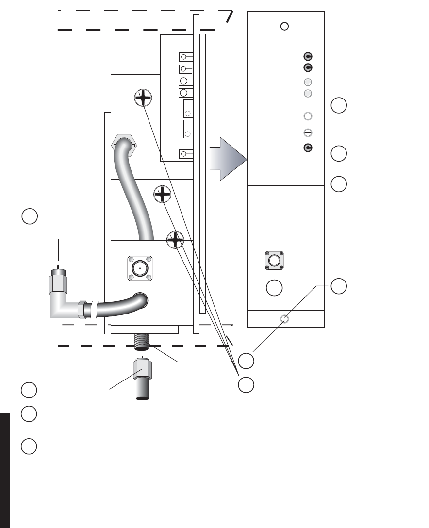
5-66
Figure 5 - 25 UD-51( ) Power Amplifier Removal and Replacement
DC MON
GND
10.5V DC
PWR ALM
TEMP ALM
DC MON ADJ
PWR ALM ADJ
POWER AMPLIFIER
RF
IN
RF
MON
MDR-1066
09/08/05
FRONT PANEL
RF OUT
P/O SHELF
P/O SHELF
REMOVE:
(Remove steps are prefixed
by the letter "R").
INSTALL:
(Install steps are prefixed
by the letter "I".
Loosen thumbscrews
and remove front panel.
Rb
Loosen mounting screws
and slide PA toward front
of card cage to access
RF OUT connector.
Rc
Disconnect RF OUT
cable.
Rd
Tilt top of PA forward
approx 45˚ to clear RF
OUT connector.
Re
Disconnect cable
from XMTR RF
OUT connector.
Ra
Remove PA from card
cage.
Rf
Install replacement PA
in shelf and tighten
mounting screws
(torque to 19 in. lbs).
Ia
Connect RF OUT
cable.
Ib
Connect RF IN cable
to XMTR RF OUT
connector.
Ic
Reinstall PA front
panel and tighten
thumbscrews.
Id
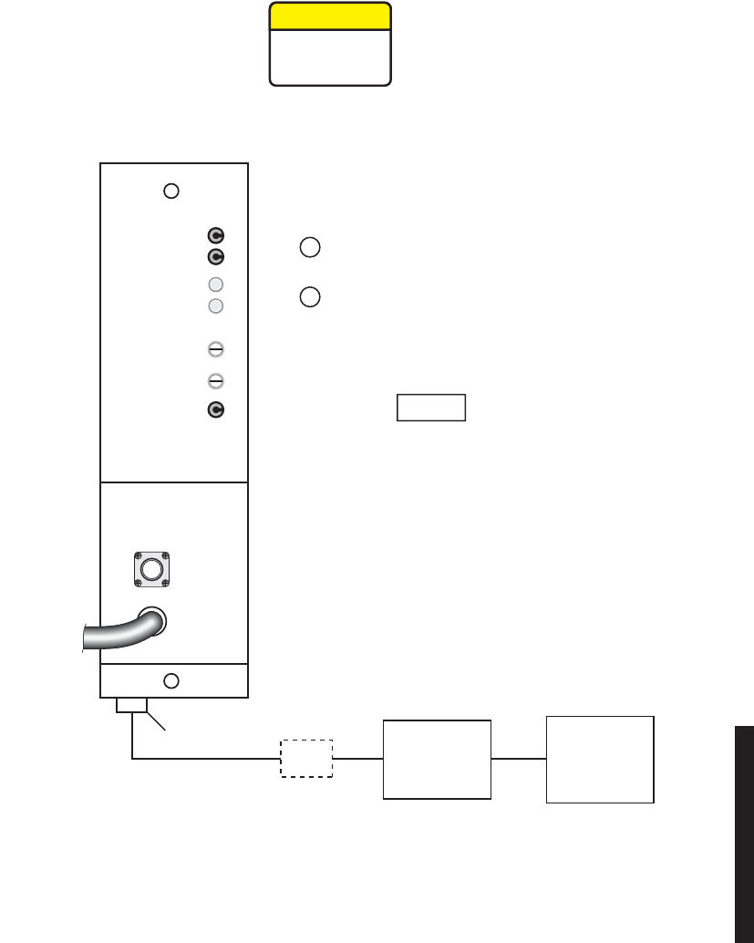
5-67
5.25 PA OUTPUT LEVEL CALIBRATION
See Figure 5 - 26 and follow procedure to check, and if necessary, adjust the UD-51( ) Power
Amplifier (PA) output in radio configuration that is equipped with the optional PA.
Figure 5 - 26 PA Output Level Calibration (Sheet 1 of 5)
MDR-1067
10/11/05
* As an alternative procedure, replace high power sensor with
a medium power sensor and install in-line 30 dB attenuator.
Attenuator must be properly calibrated for 30 dB.
HIGH
POWER
SENSOR*
POWER
METER
DC MON
GND
10.5V DC
PWR ALM
TEMP ALM
DC MON ADJ
PWR ALM ADJ
POWER AMPLIFIER
RF
IN
RF OUT
RF
MON
30 DB
PAD*
Disconnect SMA connector from
RF OUT connector.
a
Connect power meter with high
power sensor to RF OUT connector.
b
Note
If ATPC is enabled, disable (XMTR will
go to high power).
CAUTION
Possibility of
Service
Interruption
This is an out-of-service procedure when on a nonstandby
(unprotected) system. On a hot-standby or frequency diversity
system, switch traffic on the channel under test to protect.
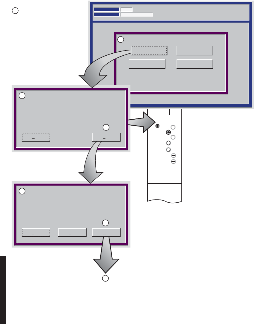
5-68
Figure 5 - 26 PA Output Level Calibration (Sheet 2 of 5)
PWR MON
XMT PWR
ALM
ON LINE
I CARR NULL
XMT LVL
ADJ
FREQ CONT
Q CARR NULL
TRANSMITTER
TRANSMIT POWER CALIBRATION
Communicating*
ELMC Address:
Description: MDR-8000
RACK6
12:17:01 PM
10-May-99
CLICK CALIBRATE A OR B SIDE
Carrier Null A Carrier Null B
Calibrate B-side
Set your Tx Level to 10 dB below nominal
HIGH power using the (XMT LVL ADJ)
potentiometer on your TRANSMITTER
module. After this is done, click Next.
Set your Tx Level to nominal HIGH power
using the (XMT LVL ADJ) potentiometer on
your TRANSMITTER module. After this is done,
click NEXT.
Calibrate A Side
MDR-1068
10/04/04
Abort Next
Abort NextBack
Example:
Expected output level at top of stack = 29 dBm.
Label on diplexer filter/XMT filter shows insertion loss is 2 dB.
Nominal high power out of PA = 31 dBm
(29 dBm + 2 dBm = 31 dBm).
Set nominal low power level for 21 dBm
(10 dB down from 31 dBm).
Proceed to
Sheet 3
Determine PA nominal high
and low output level:
c
d
e
f
g
h
i
PA nominal high output level =
level at top of stack + insertion
loss of diplexer filter/XMT filter
(marked on label on filter).
XMTR nominal low output level
= XMTR nominal high output
level -10 dB.
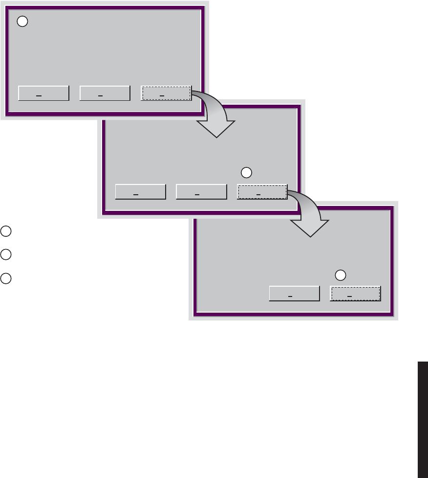
5-69
Figure 5 - 26 PA Output Level Calibration (Sheet 3 of 5)
Back Finish
Successfully stored calibration data
Storing calibration data, please wait...
CLICK NEXT.
Abort Back Next
MDR-1069
09/08/05
Abort Back
Save your calibrated values. Click next
Next
Click Finish. Calibration is
complete.
l
Reconnect cable to RF OUT
connector.
m
Observe RF MON label on PA front
panel. On label, is the measured READ
level in dBm or Vdc?
n
If labeled READ X.X dBm, go to Step o.
If labeled READ X.X Vdc, go to Step s.
j
k
i
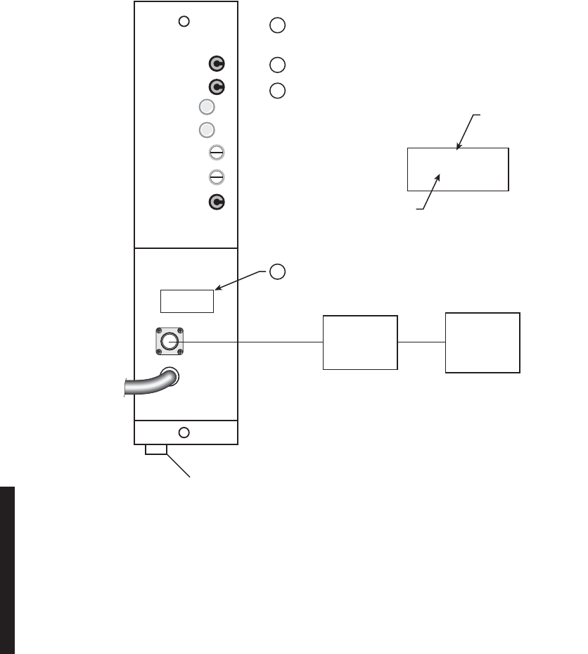
5-70
Figure 5 - 26 PA Output Level Calibration (Sheet 4 of 5)
MDR-1070
09/08/05
DC
MON
GND
10.5V DC
PWR ALM
TEMP ALM
DC MON ADJ
PWR ALM ADJ
POWER AMPLIFIER
RF
IN
RF OUT
RF
MON
MEASURED LEVEL
(STEP b).
READ X.X dBm
FOR XX.X dBm
AT TOP OF RACK
READ X.X dBm
FOR XX.X dBm
AT TOP OF RACK
EXPECTED OUTPUT LEVEL
AT TOP OF STACK
(REFER TO FIGURE 9-37 STEP 1).
POWER
SENSOR
50 OHM
POWER
METER
Connect Power Meter with 50 Ohm Power
Sensor to RF MON connector.
o
Measure RF MON level on Power Meter.
p
Make new label for RF MON:
q
Attach new label.
r
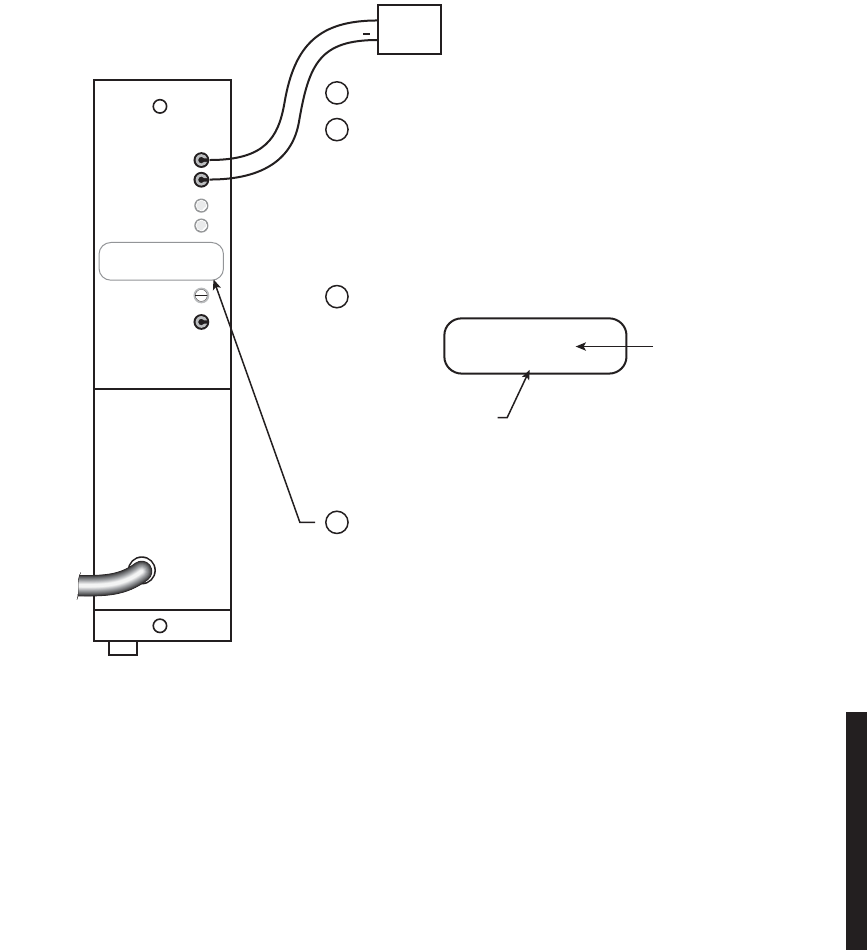
5-71
Figure 5 - 26 PA Output Level Calibration (Sheet 5 of 5)
Connect DVM to DC MON (+) test point and GND.
s
Create new label:
u
Attach new label over the top of DC MON ADJ.
v
Using DC MON ADJ on PA front panel, adjust for
voltage on DVM equaling expected level at top of
stack multiplied by 0.1.
t
DC MON
GND
10.5V DC
PWR ALM
TEMP ALM
DC MON ADJ
PWR ALM ADJ
POWER AMPLIFIER
RF
IN
MDR-1071
09/08/05
DVM
+
EXAMPLE:
EXPECTED LEVEL AT TOP OF STACK = 29 dBm
29 dBm X 0.1 (VOLTS DC/dBm) = 2.9 VOLTS DC
DC MONITOR CALIBRATION
READ [X.X Vdc]
FOR [XX.X dBm]
DC MONITOR CALIBRATION
READ [X.X Vdc]
FOR [XX.X dBm]
EXPECTED OUTPUT LEVEL
AT TOP OF STACK
REFER TO EXAMPLE ABOVE.
MEASURED LEVEL
(STEP b).

5-72
5.26 CHANGING FREQUENCY
Crystals are soldered and tuned up in a crystal oscillator sub-
board at the factory.
Changing frequencies requires changing the crystal on the crystal oscillator subboard in
the transmitter and receiver modules. Changing out the crystal requires tuning the crystal
oscillator subboard. Tuning the crystal oscillator subboard is a factory procedure.
An RF frequency change may require re-tuning the diplexer. Re-tuning the diplexer is a
factory procedure.
5.27 CLEANING
Do not use acid, alcohol, or brushes to clean modules because
damage to the silkscreen labeling and antistatic coating can
result. Cleaning should be confined to the removal of dust and
dirt using a damp cloth.
Cleaning should normally be confined to the removal of dust and dirt using a soft bristled
(natural fiber) brush and a low velocity blower (such as a vacuum cleaner with a plastic
blower nozzle). Do not use acid or synthetic bristled brushes to clean modules that contain
electrostatic-sensitive components.
CAUTION
Possibility of
Service
Interruption
CAUTION
Possibility of
Service
Interruption