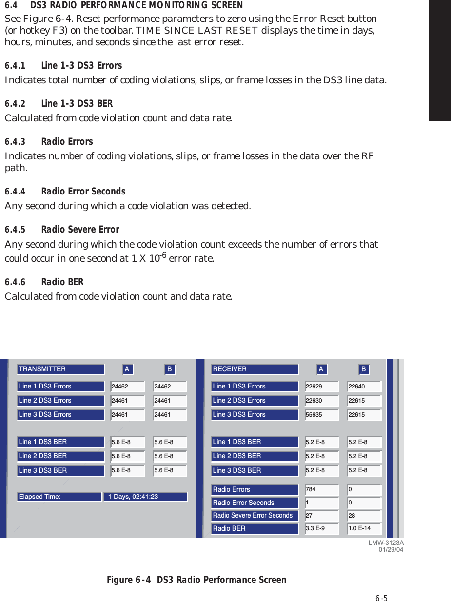
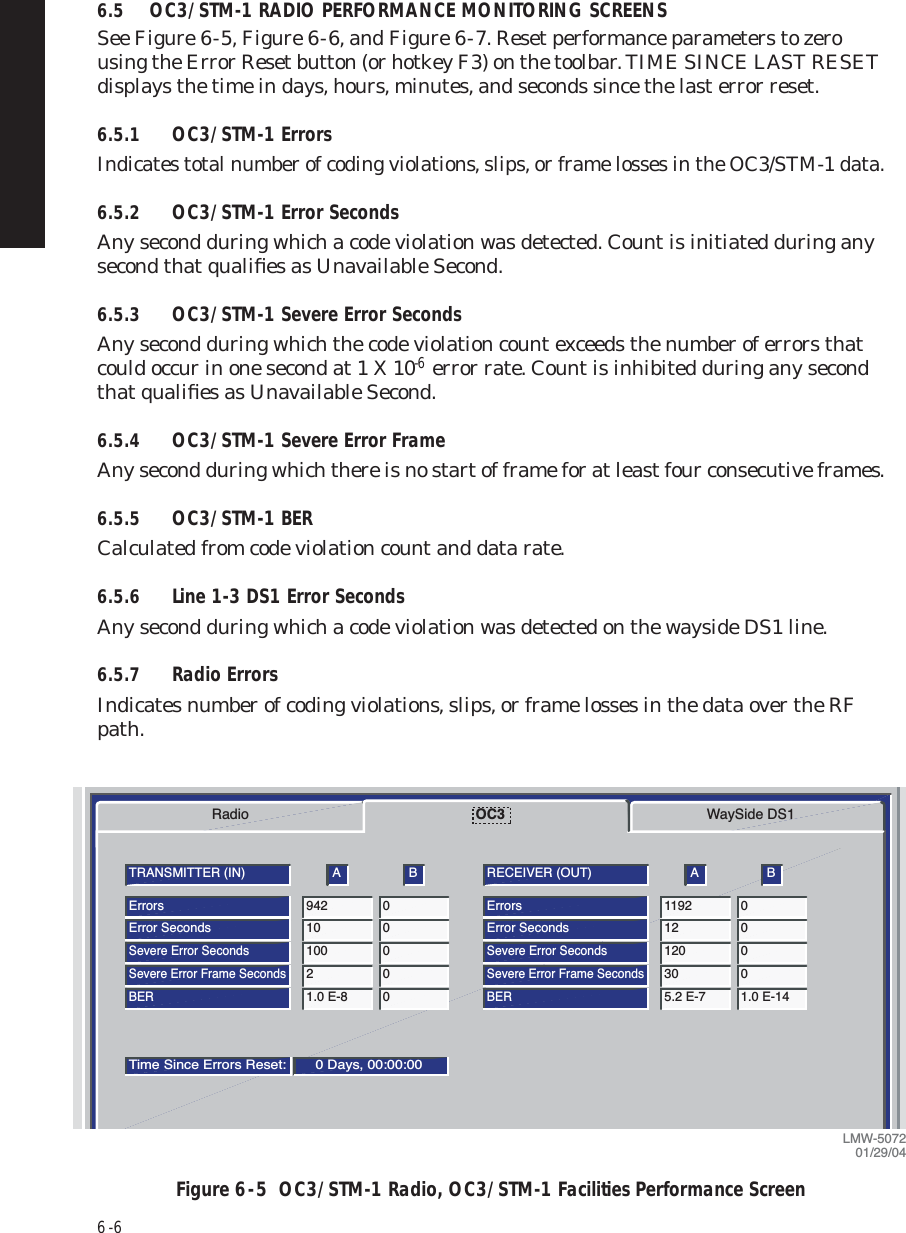
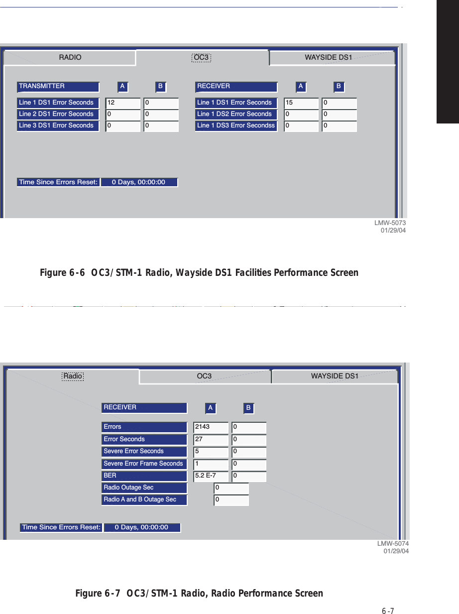
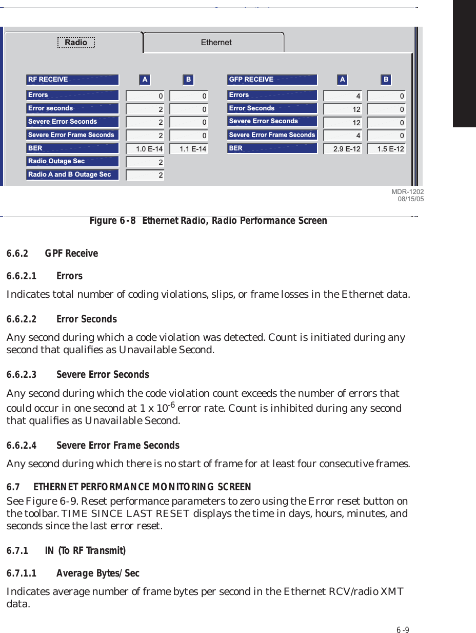
Alcatel USA 8702-50 MDR-8000 User Manual MDR 8000 Radio Family Users Manual Issue 9
Alcatel USA Marketing, Inc. MDR-8000 MDR 8000 Radio Family Users Manual Issue 9
UserManual.wiki
>
Alcatel USA
>
8702-50 User Manual
>
User manual 03
Contents
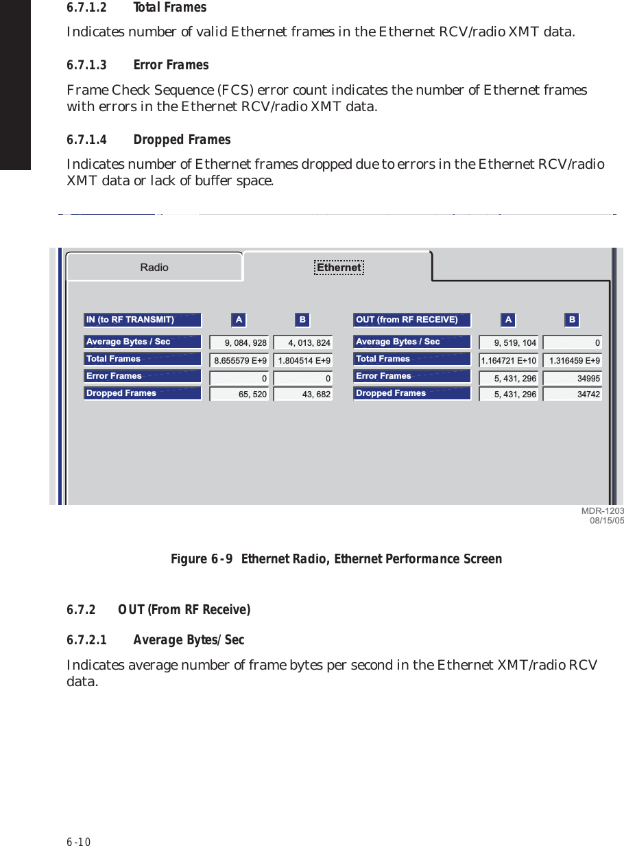
1.
User manual 01
2.
User manual 02
3.
User manual 03
User manual 03
Navigation menu
Upload a User Manual
Namespaces
Wiki Guide
HTML
PDF
Info
Views
User Manual
Discussion / Help
Navigation


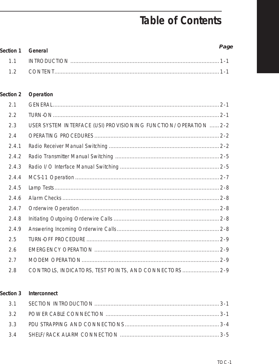
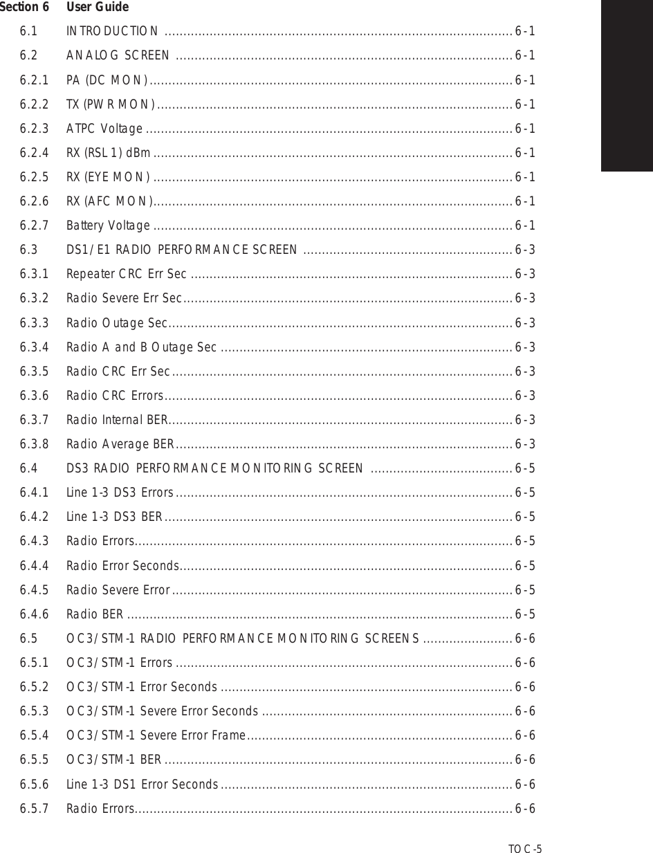
![6 - 2Figure 6 - 1 Analog Screen (Single RCVR)Figure 6 - 2 Analog Screen (Dual RCVR)TRANSMIT VoltagesA BPA (DC MON)3.13 3.03TX (PWR MON)1.91 1.95ATPC Voltage0.74 0.76RECEIVE VoltagesA BRX (RSL 1) dbm-45 dBm -53 dBmRX (EYE MON)0.09 0.19RX (AFC MON)-2.95 -2.95Battery Voltage-50.8 -51.0LOCAL ANALOGCommunicating*ELMC Address [F8]:ELMC Description:SILVERTONJ7915PerformanceAlarm StatusAnalog MonitorStation AlarmProvisioningUser ControlTuesday, July 29, 2003*Voltage not the same as PA Front Panel Test Point1:44:19 PM USI Version R1.06 Controller Version R1.06LMW-3123B01/29/04TRANSMITTERA BPA (DC MON)N/A N/ACOMMONA BBattery Voltage-53.5 -53.5TX (PWR MON)5.00 3.25ATPC Voltage0.76 0.74RECEIVERA BRX (RSL) (MN)-26 dBm -29 dBmRX (EYE MON) (MN)0.53 0.94Path Distortion (MN)2 1RX RSL (DV)-62 dBm -33 dBmRX (EYE MON) (DV)0.73 1.03Path Distortion (DV)3 2LOCAL ANALOGCommunicating***ELMC Address [F8]:ELMC Description:SILVERTONJ7915Tuesday July 29 2003*Voltage not the same as PA Front Panel Test Point1:44:19 PM USI Version R1 04 MDR 8000 OC3 Controller Version R1 04LMW-907301/29/04](https://usermanual.wiki/Alcatel-USA/8702-50.User-manual-03/User-Guide-1270260-Page-12.png)
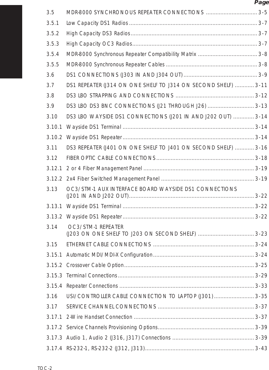
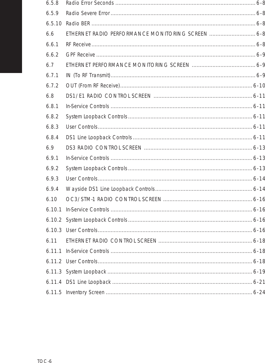
![6 - 4Figure 6 - 3 DS1/E1 Radio Performance Monitor ScreenLOCAL PERFORMANCECommunicating*ELMC Address:lowerPERFORMANCE0 DAYS , 02:24:39ELAPSED TIME: Repeater CRC Err SecRadio Severe Err SecRadio Outage SecRadio A and B Outage SecRadio CRC Err SecRadio CRC ErrorsRadio Interval BERRadio Average BERA B000 000000.00E-1200000Thursday, March 16, 20002:15:29 PMLMW-800501/29/043 WAYS TO OPEN ANALOG MONITOR SCREEN3. PRESS F5 ON KEYBOARDFileAnalog and Performance Monitoring -- MDR-8000View Setup OptionsAlarm Status [F4] Perf Monitor [F5] Station Alarm [F6] Control [F7] Provisioning [F9]2. CLICK HEREError Reset [F3]Alarm StatusPerformanceStation AlarmControlProvisioningInventoryPower AdjustRSLF4F5F6F7F9F12Ctl+TCtl+R1. CLICK HERE](https://usermanual.wiki/Alcatel-USA/8702-50.User-manual-03/User-Guide-1270260-Page-14.png)
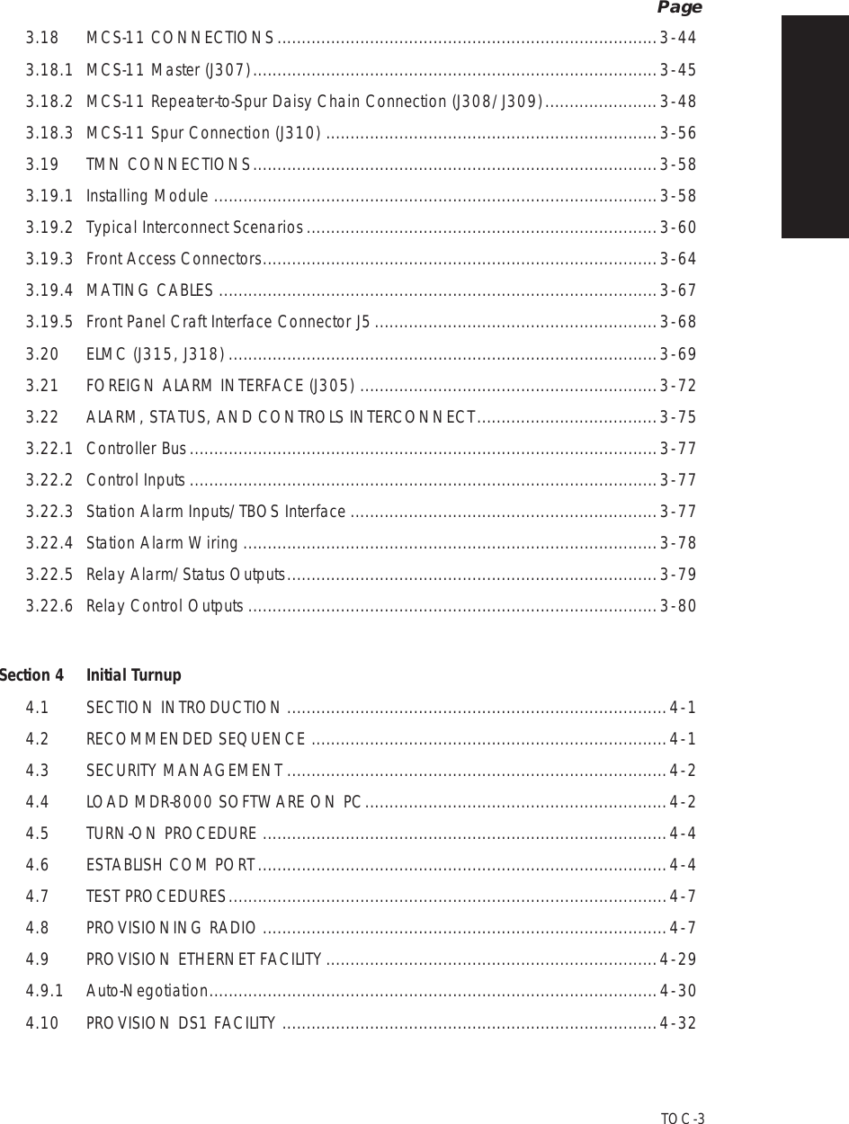
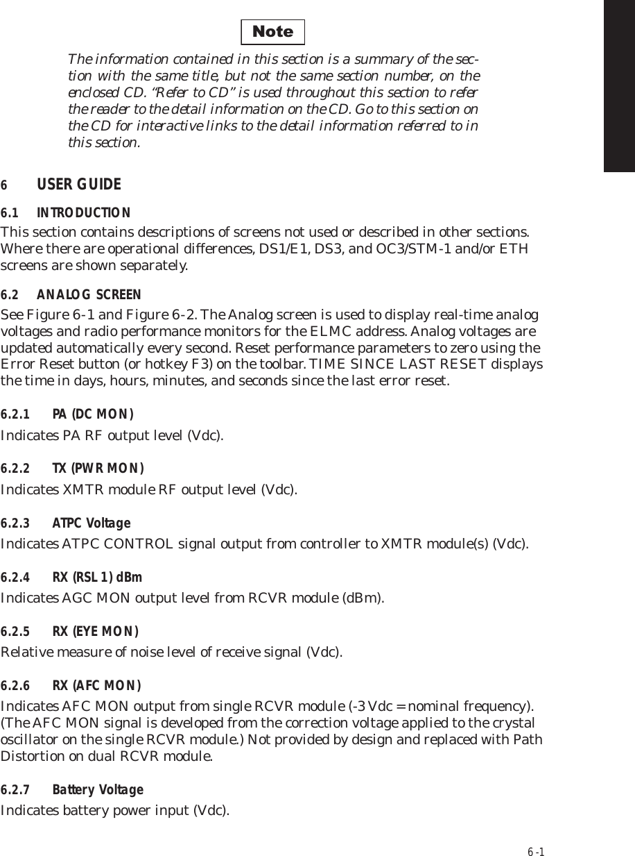
![6 - 12Figure 6 - 10 DS1/E1 Radio Control ScreenLOCAL CONTROLCommunicatingELMC Address:Description:DURANGOJ7914Thursday, March 16, 200010:15:49 AMIN-SERVICEA Transmitter On LineB Transmitter On LineA Receiver On LineA I/O On LineB I/O On LineB Receiver On LineA ATPC High Power LockB ATPC High Power LockA ATPC Low Power LockB ATPC Low Power LockLine 1 loopbackLine 2 loopbackLine 3 loopbackLine 4 loopbackLine 5 loopbackLine 6 loopbackLine 7 loopbackLine 8 loopbackLine 9 loopbackLine 10 loopbackLine 11 loopbackLine 12 loopbackLine 13 loopbackLine 14 loopbackLine 15 loopbackLine 16 loopbackSYSTEM LOOPBACKI/O LOOPBACKUSER CONTROLSGEN STARTTWR LIGHT OVRDUser Control #3User Control #4User Control #5User Control #6DS1 LINE LOOPBACK RCV to XMT2. CLICK HERE3 WAYS TO OPEN CONTROL SCREEN3. PRESS F7 ON KEYBOARDFileControls -- MDR-8000 DS1View Setup OptionsAlarm Status [F4] Perf Monitor [F5] Station Alarm [F6] Control [F7] Provisioning [F9]Alarm StatusPerformanceStation AlarmControlProvisioningInventoryPower AdjustRSLF4F5F6F7F9F12Ctl+PCtl+R1. CLICK HERELMW-100601/29/04ACTIVEHIGHLIGHT AND SELECT "YES" ON CONFIRMATION MESSAGE TO ENABLE FUNCTION](https://usermanual.wiki/Alcatel-USA/8702-50.User-manual-03/User-Guide-1270260-Page-22.png)
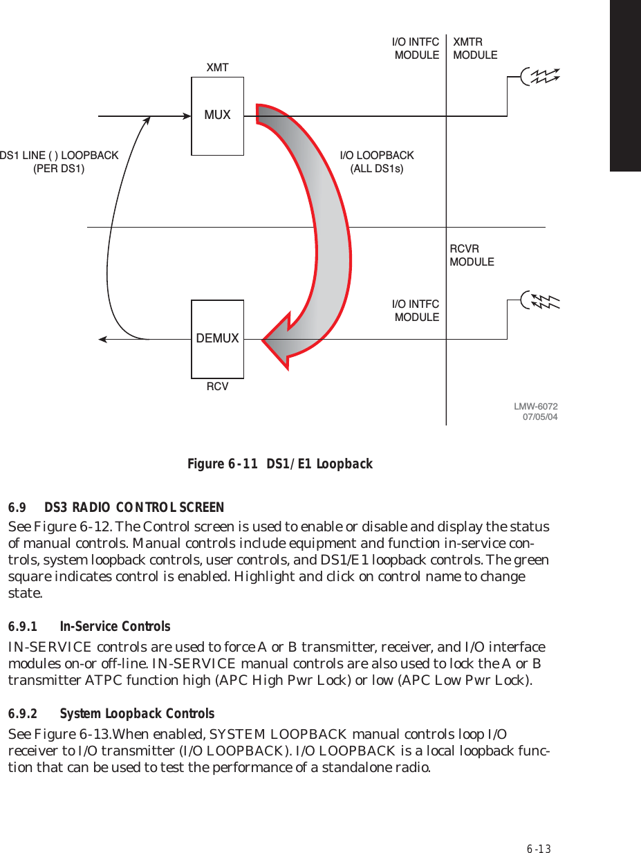
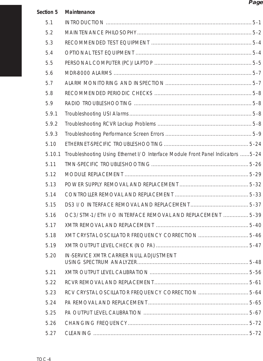
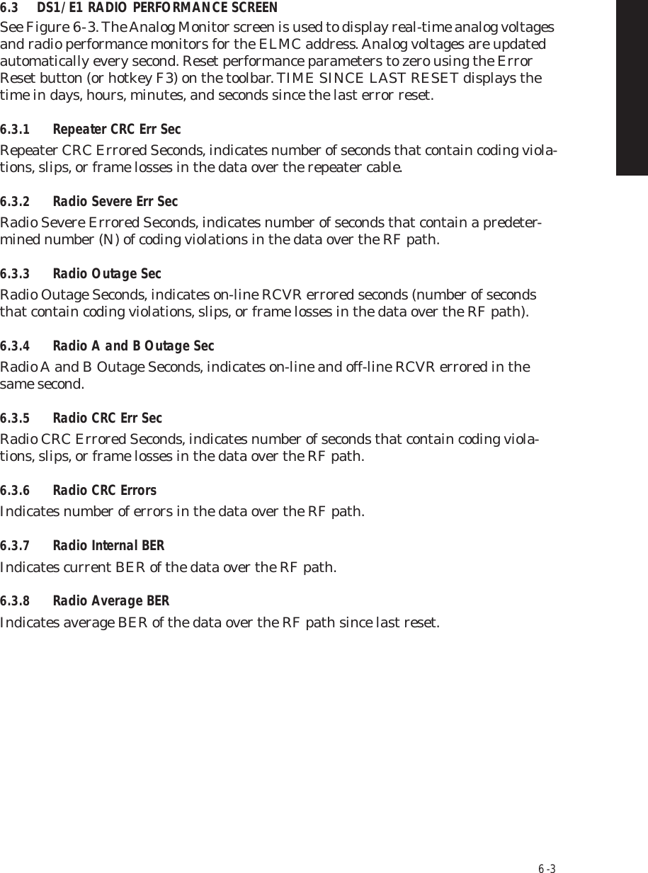
![6 - 246.11.5 Inventory ScreenSee Figure 6 - 21 for Inventory Screen. The inventory screen is used to display current shelf inventory, including module type number, module part number, hardware revi-sion, software revision (if applicable), serial number, and remarks (if any).Inventory is automatically updated if modules are replaced. Manual changes to the inventory list on the screen are performed only in the factory.Figure 6 - 21 Inventory ScreenTuesday, November 30, 2004 3:31:44 PM Universal USI Version P2.00q MDR-8000 OC3 Controller Version P3.13Side A CommonSide BExportCancel ClearRefreshStoreSelect All TYPE Part Number RV MRev ICS S/W REV Serial Number MiscTransmitter UD-35AQ-4 3DH03236AD AA 01 01 CA02D546Transmitter Cap Key N/A 3EM04177AB AB 02 0100CA07D577Transmitter Oscillator N/A 3DH04123AC AB 01Power Amplifier UD-16BB-2 3DH03218AA AA 03 01 L50W8389Power Supply DS-35P-2 3DH03164AB AB 01 01 EM1I/O Interface UD-36AQ-10 3EM03134AB AB 01 01 R02.01 CA09W929CA09W146Receiver AE 27AF-1 3DH03239AD3EM04177ABAA 01 0101 CA02D619Receiver Cap Key N/AReceiver Oscillator N/A 3DH04123AC AA 01 00 02ABELMC Address: R101LOCAL INVENTORY (RS-232)Communicating***Alcatel User Interface – [Universal USI -- Inventory]F6PerformanceAlarm StatusF4Station AlarmF7 F9User ControlF8F5Prov. SaveF3ProvisioningFile View Setup OptionsMDR-116211/21/06Realization Variant - identifies differences in design within family itemField Not ApplicableManufacturing Revision - identifies enhancement-type changesItem Change Status - identifies source of part](https://usermanual.wiki/Alcatel-USA/8702-50.User-manual-03/User-Guide-1270260-Page-34.png)