Alcon Research PUREPT1 PurePoint User Manual NGL Book 1 indb

Alcon Research Ltd. PurePoint NGL Book 1 indb

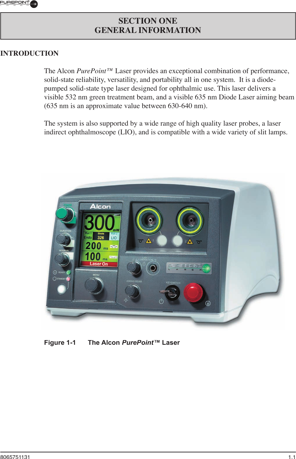
User Manual part 1 of 5

OPERATOR'S MANUALManufacturer:  EU Authorized Representative:Alcon Laboratories, Inc.  Alcon Laboratories (U.K.) Ltd.6201 South Freeway  Boundary Way, Hemel HempsteadFort Worth, Texas 76134-2099  Hertfordshire, HP2 7UD EnglandU.S.A.Produced By:Alcon Laboratories, Inc.15800 Alton ParkwayIrvine, California 92618-3818U.S.A.Telephone:  949/753-1393  800/832-7827FAX:  949/753-66148065751131 Rev. P3.5, CATALOG NUMBER905-5620-001 Rev. P3.5, TEXT ONLY    © 2007 Alcon, Inc.
ii  8065751131PurePoint™ Operator's8065751131MANUAL REVISION RECORD  DATE  REVISION  ECN NUMBER AND DESCRIPTION  DATE  REVISION  ECN NUMBER AND DESCRIPTION  DATE  REVISION  ECN NUMBER AND DESCRIPTIONCSO is a registered trademark of Costruzione Strumenti Oftalmici S.R.L.Nikon is a registered trademark of Nikon Inc. Corporation.Topcon is a registered trademark of Kabushiki Kaisha Topcon Corporation. Meditec is a registered trademark of Meditec Reinhardt Thysel GMBH.Ellex is a registered trademark of Taracan Pty. Ltd.Zeiss is a registered trademark of Carl-Zeiss-Stifl ung.Haag-Streit is a registered trademark of Haag-Streit AG Corporation.Heine is a registered trademark of Hein Optotechnik GmbH.* Registered U.S. Patent & Trademark Offi ce
8065751131 iiiTABLE OF CONTENTSTOPIC  PAGE #Manual Revision Record . . . . . . . . . . . . . . . . . . . . . . . . . . . . . . . . . . . . . . . . . . . . . . . . . . . . . . . . . . . . . . . . . . . iiForeword . . . . . . . . . . . . . . . . . . . . . . . . . . . . . . . . . . . . . . . . . . . . . . . . . . . . . . . . . . . . . . . . . . . . . . . . . . . . . . .viImportant Notice . . . . . . . . . . . . . . . . . . . . . . . . . . . . . . . . . . . . . . . . . . . . . . . . . . . . . . . . . . . . . . . . . . . . . . . . . viiSECTION ONE - GENERAL INFORMATIONIntroduction . . . . . . . . . . . . . . . . . . . . . . . . . . . . . . . . . . . . . . . . . . . . . . . . . . . . . . . . . . . . . . . . . . . . . . . . . . . . 1.1Technical Specifi cations . . . . . . . . . . . . . . . . . . . . . . . . . . . . . . . . . . . . . . . . . . . . . . . . . . . . . . . . . . . . . . . . . . . 1.2Laser Characteristics . . . . . . . . . . . . . . . . . . . . . . . . . . . . . . . . . . . . . . . . . . . . . . . . . . . . . . . . . . . . . . . . . . . . . 1.2Environmental Considerations . . . . . . . . . . . . . . . . . . . . . . . . . . . . . . . . . . . . . . . . . . . . . . . . . . . . . . . . . . . . . . 1.3Universal Precautions . . . . . . . . . . . . . . . . . . . . . . . . . . . . . . . . . . . . . . . . . . . . . . . . . . . . . . . . . . . . . . . . . . . . . 1.4EMC Statement . . . . . . . . . . . . . . . . . . . . . . . . . . . . . . . . . . . . . . . . . . . . . . . . . . . . . . . . . . . . . . . . . . . . . . . . . 1.4FCC and IC Compliance Statement . . . . . . . . . . . . . . . . . . . . . . . . . . . . . . . . . . . . . . . . . . . . . . . . . . . . . . . . . . FCC and IC Compliance Statement . . . . . . . . . . . . . . . . . . . . . . . . . . . . . . . . . . . . . . . . . . . . . . . . . . . . . . . . . . FCC and IC Compliance Statement1.7Labeling . . . . . . . . . . . . . . . . . . . . . . . . . . . . . . . . . . . . . . . . . . . . . . . . . . . . . . . . . . . . . . . . . . . . . . . . . . . . . . . 1.8Carring Case . . . . . . . . . . . . . . . . . . . . . . . . . . . . . . . . . . . . . . . . . . . . . . . . . . . . . . . . . . . . . . . . . . . . . . . . . . . . 1.9Preparing For Installation . . . . . . . . . . . . . . . . . . . . . . . . . . . . . . . . . . . . . . . . . . . . . . . . . . . . . . . . . . . . . . . . . 1.10PurePoint™ Laser Safety Features . . . . . . . . . . . . . . . . . . . . . . . . . . . . . . . . . . . . . . . . . . . . . . . . . . . . . . . . . 1.13Professional Operator’s Information . . . . . . . . . . . . . . . . . . . . . . . . . . . . . . . . . . . . . . . . . . . . . . . . . . . . . . . . 1.14Product Service . . . . . . . . . . . . . . . . . . . . . . . . . . . . . . . . . . . . . . . . . . . . . . . . . . . . . . . . . . . . . . . . . . . . . . . . . 1.17Limited Warranty . . . . . . . . . . . . . . . . . . . . . . . . . . . . . . . . . . . . . . . . . . . . . . . . . . . . . . . . . . . . . . . . . . . . . . . 1.18SECTION TWO - DESCRIPTIONIntroduction . . . . . . . . . . . . . . . . . . . . . . . . . . . . . . . . . . . . . . . . . . . . . . . . . . . . . . . . . . . . . . . . . . . . . . . . . . . . 2.1Front Panel Description . . . . . . . . . . . . . . . . . . . . . . . . . . . . . . . . . . . . . . . . . . . . . . . . . . . . . . . . . . . . . . . . . . . 2.1Rear Panel Description . . . . . . . . . . . . . . . . . . . . . . . . . . . . . . . . . . . . . . . . . . . . . . . . . . . . . . . . . . . . . . . . . . . . 2.7Footswitch . . . . . . . . . . . . . . . . . . . . . . . . . . . . . . . . . . . . . . . . . . . . . . . . . . . . . . . . . . . . . . . . . . . . . . . . . . . . . 2.8System Modes . . . . . . . . . . . . . . . . . . . . . . . . . . . . . . . . . . . . . . . . . . . . . . . . . . . . . . . . . . . . . . . . . . . . . . . . . . 2.9Treatment Modes . . . . . . . . . . . . . . . . . . . . . . . . . . . . . . . . . . . . . . . . . . . . . . . . . . . . . . . . . . . . . . . . . . . . . . . . 2.9Screen Descriptions . . . . . . . . . . . . . . . . . . . . . . . . . . . . . . . . . . . . . . . . . . . . . . . . . . . . . . . . . . . . . . . . . . . . . 2.10SECTION THREE - OPERATING INSTRUCTIONSIntroduction . . . . . . . . . . . . . . . . . . . . . . . . . . . . . . . . . . . . . . . . . . . . . . . . . . . . . . . . . . . . . . . . . . . . . . . . . . . . 3.11  Initial Setup . . . . . . . . . . . . . . . . . . . . . . . . . . . . . . . . . . . . . . . . . . . . . . . . . . . . . . . . . . . . . . . . . . . . . . . . . . 3.12  System Connections . . . . . . . . . . . . . . . . . . . . . . . . . . . . . . . . . . . . . . . . . . . . . . . . . . . . . . . . . . . . . . . . . . . . 3.13  System Power Up And Set Up . . . . . . . . . . . . . . . . . . . . . . . . . . . . . . . . . . . . . . . . . . . . . . . . . . . . . . . . . . . . 3.44  Normal Operating Procedure . . . . . . . . . . . . . . . . . . . . . . . . . . . . . . . . . . . . . . . . . . . . . . . . . . . . . . . . . . . . . 3.75  Turn Off Sequence . . . . . . . . . . . . . . . . . . . . . . . . . . . . . . . . . . . . . . . . . . . . . . . . . . . . . . . . . . . . . . . . . . . . . 3.96  Changing The System Settings . . . . . . . . . . . . . . . . . . . . . . . . . . . . . . . . . . . . . . . . . . . . . . . . . . . . . . . . . . . 3.107  Identifying Unrecognized Probes . . . . . . . . . . . . . . . . . . . . . . . . . . . . . . . . . . . . . . . . . . . . . . . . . . . . . . . . . 3.11SECTION FOUR - CARE AND MAINTENANCEIntroduction . . . . . . . . . . . . . . . . . . . . . . . . . . . . . . . . . . . . . . . . . . . . . . . . . . . . . . . . . . . . . . . . . . . . . . . . . . . . 4.1Care And Cleaning . . . . . . . . . . . . . . . . . . . . . . . . . . . . . . . . . . . . . . . . . . . . . . . . . . . . . . . . . . . . . . . . . . . . . . . 4.1Fuse Replacement Procedure . . . . . . . . . . . . . . . . . . . . . . . . . . . . . . . . . . . . . . . . . . . . . . . . . . . . . . . . . . . . . . . 4.2Calibration Verifi cation . . . . . . . . . . . . . . . . . . . . . . . . . . . . . . . . . . . . . . . . . . . . . . . . . . . . . . . . . . . . . . . . . . . 4.3System Calibration . . . . . . . . . . . . . . . . . . . . . . . . . . . . . . . . . . . . . . . . . . . . . . . . . . . . . . . . . . . . . . . . . . . . . . . 4.9Aiming Beam/LIO Illumination Calibration . . . . . . . . . . . . . . . . . . . . . . . . . . . . . . . . . . . . . . . . . . . . . . . . . . 4.11SECTION FIVE - TROUBLESHOOTINGSystem Messages . . . . . . . . . . . . . . . . . . . . . . . . . . . . . . . . . . . . . . . . . . . . . . . . . . . . . . . . . . . . . . . . . . . . . . . . 5.1SECTION SIX - ACCESSORIES AND PARTS . . . . . . . . . . . . . . . . . . . . . . . . . . . . . . . . . . . . . . . . . . . . . . 6.1SECTION SEVEN - INDEX . . . . . . . . . . . . . . . . . . . . . . . . . . . . . . . . . . . . . . . . . . . . . . . . . . . . . . . . . . . . . . 7.1
iv  8065751131FIGURE #  TITLE  PAGE #LIST OF ILLUSTRATIONSFigure 1-1  The Alcon PurePoint™ Laser . . . . . . . . . . . . . . . . . . . . . . . . . . . . . . . . . . . . . . . . . . . . . . . . . . .  Laser . . . . . . . . . . . . . . . . . . . . . . . . . . . . . . . . . . . . . . . . . . . . . . . . . . .  Laser1.1Figure 1-2  Labels and Icons used on the PurePoint™ LaserConsole . . . . . . . . . . . . . . . . . . . . . . . . . . . . . 1.7Figure 1-3  The PurePoint™ Carrying Case . . . . . . . . . . . . . . . . . . . . . . . . . . . . . . . . . . . . . . . . . . . . . . . . . 1.8Figure 1-4  Recommended Laser Room Layout . . . . . . . . . . . . . . . . . . . . . . . . . . . . . . . . . . . . . . . . . . . . . 1.10Figure 1-5  Remote Connector/Door Lamp Circuit Diagram . . . . . . . . . . . . . . . . . . . . . . . . . . . . . . . . . . . 1.12Figure 1-6Dr. Filter Message . . . . . . . . . . . . . . . . . . . . . . . . . . . . . . . . . . . . . . . . . . . . . . . . . . . . . . . . . . . 1.15Figure 2-1  The PurePoint Laser Front Panel . . . . . . . . . . . . . . . . . . . . . . . . . . . . . . . . . . . . . . . . . . . . . . . . 2.1Figure 2-2Typical PurePoint™ Screen . . . . . . . . . . . . . . . . . . . . . . . . . . . . . . . . . . . . . . . . . . . . . . . . . . . . 2.2Figure 2-3  Unidentifi able Probe Selection Screen . . . . . . . . . . . . . . . . . . . . . . . . . . . . . . . . . . . . . . . . . . . . 2.3Figure 2-4 The PurePoint™ Laser Rear Panel . . . . . . . . . . . . . . . . . . . . . . . . . . . . . . . . . . . . . . . . . . . . . . . 2.2Figure 2-5 The PurePoint™ Laser Footswitch . . . . . . . . . . . . . . . . . . . . . . . . . . . . . . . . . . . . . . . . . . . . . . . 2.7Figure 2-6 Screens Displayed on the PurePoint™ LCD . . . . . . . . . . . . . . . . . . . . . . . . . . . . . . . . . . . . . . 2.10Figure 2-7Initialization Screen . . . . . . . . . . . . . . . . . . . . . . . . . . . . . . . . . . . . . . . . . . . . . . . . . . . . . . . . . 2.11Figure 2-8Standby Screen . . . . . . . . . . . . . . . . . . . . . . . . . . . . . . . . . . . . . . . . . . . . . . . . . . . . . . . . . . . . . 2.11Figure 2-9Ready Screen . . . . . . . . . . . . . . . . . . . . . . . . . . . . . . . . . . . . . . . . . . . . . . . . . . . . . . . . . . . . . . . 2.12Figure 2-10Laser On Screen . . . . . . . . . . . . . . . . . . . . . . . . . . . . . . . . . . . . . . . . . . . . . . . . . . . . . . . . . . . . 2.12Figure 2-11Main Menu . . . . . . . . . . . . . . . . . . . . . . . . . . . . . . . . . . . . . . . . . . . . . . . . . . . . . . . . . . . . . . . . 2.12Figure 2-12Settings Menu . . . . . . . . . . . . . . . . . . . . . . . . . . . . . . . . . . . . . . . . . . . . . . . . . . . . . . . . . . . . . . 2.13Figure 2-13Audio Settings . . . . . . . . . . . . . . . . . . . . . . . . . . . . . . . . . . . . . . . . . . . . . . . . . . . . . . . . . . . . . . 2.13Figure 2-14  Contrast Settings . . . . . . . . . . . . . . . . . . . . . . . . . . . . . . . . . . . . . . . . . . . . . . . . . . . . . . . . . . . . 2.14Figure 2-15  Fiber Custom Pre-Sets Screen . . . . . . . . . . . . . . . . . . . . . . . . . . . . . . . . . . . . . . . . . . . . . . . . . . 2.14Figure 2-16Footswitch Settings . . . . . . . . . . . . . . . . . . . . . . . . . . . . . . . . . . . . . . . . . . . . . . . . . . . . . . . . . . 2.15Figure 2-17Language Settings . . . . . . . . . . . . . . . . . . . . . . . . . . . . . . . . . . . . . . . . . . . . . . . . . . . . . . . . . . . 2.15Figure 2-18Revert to Standby Settings . . . . . . . . . . . . . . . . . . . . . . . . . . . . . . . . . . . . . . . . . . . . . . . . . . . . 2.16Figure 2-19Treatment Totals Settings . . . . . . . . . . . . . . . . . . . . . . . . . . . . . . . . . . . . . . . . . . . . . . . . . . . . . 2.16Figure 2-20System Information Menu . . . . . . . . . . . . . . . . . . . . . . . . . . . . . . . . . . . . . . . . . . . . . . . . . . . . 2.17Figure 2-21  About PurePoint™ Screen . . . . . . . . . . . . . . . . . . . . . . . . . . . . . . . . . . . . . . . . . . . . . . . . . . . . 2.17Figure 2-22Version Numbers  . . . . . . . . . . . . . . . . . . . . . . . . . . . . . . . . . . . . . . . . . . . . . . . . . . . . . . . . . . . 2.17Figure 2-23System Messages . . . . . . . . . . . . . . . . . . . . . . . . . . . . . . . . . . . . . . . . . . . . . . . . . . . . . . . . . . . 2.18Figure 2-24System Totals . . . . . . . . . . . . . . . . . . . . . . . . . . . . . . . . . . . . . . . . . . . . . . . . . . . . . . . . . . . . . . 2.18Figure 2-25Reset to Factory Defaults Display  . . . . . . . . . . . . . . . . . . . . . . . . . . . . . . . . . . . . . . . . . . . . . . 2.18Figure 3-1 Slit Lamp Connections . . . . . . . . . . . . . . . . . . . . . . . . . . . . . . . . . . . . . . . . . . . . . . . . . . . . . . . . 3.3Figure 3-2 Display During Initialization . . . . . . . . . . . . . . . . . . . . . . . . . . . . . . . . . . . . . . . . . . . . . . . . . . . 3.4Figure 3-3 Transition from Standby to Ready Mode . . . . . . . . . . . . . . . . . . . . . . . . . . . . . . . . . . . . . . . . . . 3.8Figure 3-4 Transition from Ready State to Laser On . . . . . . . . . . . . . . . . . . . . . . . . . . . . . . . . . . . . . . . . . . 3.8Figure 3-5Transition from Laser On to Standby because of a Warning Condition  . . . . . . . . . . . . . . . . . . 3.9Figure 3-6 Main Menu . . . . . . . . . . . . . . . . . . . . . . . . . . . . . . . . . . . . . . . . . . . . . . . . . . . . . . . . . . . . . . . . 3.10Figure 3-7 Settings Menu . . . . . . . . . . . . . . . . . . . . . . . . . . . . . . . . . . . . . . . . . . . . . . . . . . . . . . . . . . . . . . 3.10Figure 3-8 Unidentifiable Probe Display . . . . . . . . . . . . . . . . . . . . . . . . . . . . . . . . . . . . . . . . . . . . . . . . . . 3.11Figure 4-1  Exposure Time Test Configuration . . . . . . . . . . . . . . . . . . . . . . . . . . . . . . . . . . . . . . . . . . . . . . . 4.4Figure 4-2  Power Test Configuration . . . . . . . . . . . . . . . . . . . . . . . . . . . . . . . . . . . . . . . . . . . . . . . . . . . . . . 4.5Figure 5-1 Error Message . . . . . . . . . . . . . . . . . . . . . . . . . . . . . . . . . . . . . . . . . . . . . . . . . . . . . . . . . . . . . . . 5.2Figure 6-1 Alcon SL1000 Slit Lamp . . . . . . . . . . . . . . . . . . . . . . . . . . . . . . . . . . . . . . . . . . . . . . . . . . . . . . 6.2Figure 6-2Zeiss 30SL . . . . . . . . . . . . . . . . . . . . . . . . . . . . . . . . . . . . . . . . . . . . . . . . . . . . . . . . . . . . . . . . . . Zeiss 30SL . . . . . . . . . . . . . . . . . . . . . . . . . . . . . . . . . . . . . . . . . . . . . . . . . . . . . . . . . . . . . . . . . . Zeiss 30SL6.2Figure 6-3Haag-Streit 900BM . . . . . . . . . . . . . . . . . . . . . . . . . . . . . . . . . . . . . . . . . . . . . . . . . . . . . . . . . . 6.3Figure 6-4Doctor Protection Filter Mounted Between Binoculars and Slit Lamp Assembly . . . . . . . . . . . 6.4Figure 6-5 Label Location Diagram on Adaptation - Alcon SL 1000 shown . . . . . . . . . . . . . . . . . . . . . . . . 6.6Figure 6-6To avoid injury, the beam splitter/accessories must be placedbetween the binoculars   and Doctor Protection Filter (Alcon SL 1000 shown) . . . . . . . . . . . . . . . . . . . . . . . . . . . . . . . . 6.6Figure 6-7Controls on Alcon SL 1000 Slit Lamp with Doctor Protection Filter and Adaptation Installed . 6.7Figure 6-8Laser Spot Focus . . . . . . . . . . . . . . . . . . . . . . . . . . . . . . . . . . . . . . . . . . . . . . . . . . . . . . . . . . . . . 6.9
8065751131 vLIST OF TABLESTable 1-1Technical Specifi cations . . . . . . . . . . . . . . . . . . . . . . . . . . . . . . . . . . . . . . . . . . . . . . . . . . . . . . . 1.2Table 1-2Laser Characteristics . . . . . . . . . . . . . . . . . . . . . . . . . . . . . . . . . . . . . . . . . . . . . . . . . . . . . . . . . . 1.2Table 1-3  Guidance and Manufacturer's Declaration - Electromagnetic Emissions  . . . . . . . . . . . . . . . . . 1.4Table 1-4  Guidance and Manufacturer's Declaration - Electromagnetic Immunity . . . . . . . . . . . . . . . . . . 1.5Table 1-5  Recommended Separation Distances Between Portable and Mobile RF  Communications Equipment and the PurePointPurePointPur™ Laser . . . . . . . . . . . . . . . . . . . . . . . . . . . . . 1.6Table 2-1  532 Green Laser Power Values (in milliwatts) . . . . . . . . . . . . . . . . . . . . . . . . . . . . . . . . . . . . . . 2.2Table 4-1  Energy Matrix . . . . . . . . . . . . . . . . . . . . . . . . . . . . . . . . . . . . . . . . . . . . . . . . . . . . . . . . . . . . . . . 4.7Table 6-1PurePoint™ Laser Accessories . . . . . . . . . . . . . . . . . . . . . . . . . . . . . . . . . . . . . . . . . . . . . . . . . . 6.1Table 6-2 Adaptation Troubleshooting . . . . . . . . . . . . . . . . . . . . . . . . . . . . . . . . . . . . . . . . . . . . . . . . . . . . 6.9Table 6-3Alcon LIO-AT Technical Specifi cations . . . . . . . . . . . . . . . . . . . . . . . . . . . . . . . . . . . . . . . . . . 6.12TABLE #  TITLE  PAGE #Figure 6-9  Alcon LIO-AT . . . . . . . . . . . . . . . . . . . . . . . . . . . . . . . . . . . . . . . . . . . . . . . . . . . . . . . . . . . . . . 6.10Figure 6-10  Alcon LIO-AT Labeling . . . . . . . . . . . . . . . . . . . . . . . . . . . . . . . . . . . . . . . . . . . . . . . . . . . . . . 6.12Figure 6-11  Adjusting the LIO-AT Overband . . . . . . . . . . . . . . . . . . . . . . . . . . . . . . . . . . . . . . . . . . . . . . . 6.14Figure 6-12  LIO-AT Controls and Adjustments . . . . . . . . . . . . . . . . . . . . . . . . . . . . . . . . . . . . . . . . . . . . . . 6.15Figure 6-13  Eyecup Retainers and Ocular Lens on the Alcon LIO-AT . . . . . . . . . . . . . . . . . . . . . . . . . . . . 6.16Figure 6-14  Alcon LIO-AT Bulb Replacement . . . . . . . . . . . . . . . . . . . . . . . . . . . . . . . . . . . . . . . . . . . . . . 6.20FIGURE #  TITLE  PAGE #LIST OF ILLUSTRATIONS
vi  8065751131FOREWORDThis Operator's Manual is designed to acquaint the operator and operating room personnel with the Next Generation Laser.  The manual presents an organized summary of the operating principles, main components, safety features, and instructions for care and use of the instrument.The information in this manual should be supplemented with reference works on laser theory and the interaction of laser energy with biologic tissues.  No attempt is made in this manual to answer all the questions that arise during the use of the instrument in medical procedures.Questions concerning technique, safety and effectiveness should be referred to pertinent publications or recognized medical experts in laser surgery.  Physicians should not attempt to treat patients with this instrument if not thoroughly familiar with its operation, or if in doubt as to its safe operation.  All personnel authorized to use this instrument should be required to be thoroughly familiar with this manual. Please contact Alcon for complete technical support and service if you have questions concerning any aspect of this instrument's operation or if it fails to perform satisfactorily.To order supplies in U.S.A.:  800-862-5266  FAX:  800-241-0677Outside U.S.A.:  Contact your local Alcon representative for supplies.
8065751131 viiIMPORTANT NOTICEEquipment improvement is an on-going process and, as such, changes may be made to the equipment after this manual is printed.Pay close attention to WARNINGS and CAUTIONS in this manual. WARNINGS are written to protect individuals from bodily harm. CAUTIONS are written to protect the instrument from damage. Illustrations contained in this manual are for reference only.It is recommended that maintenance be performed by a qualifi ed Alcon Field Engineer.Alcon Surgical shall not be liable for any damage resulting from failure to comply with the enclosed instructions. Alcon reserves the right to change specifi cations without further notice.CAUTIONU.S. Federal Law restricts this device to sale by or on the order of a physician only.WARNINGS!Use of controls or adjustments, or performance of procedures other than those specifi ed herein may result in hazardous laser radiation exposure.A qualifi ed technician must perform a visual inspection of the following components every twelve months. In case of a defi ciency, do not use the system; call Alcon Technical Services.  - Warning Labels  - Power Cord  - FusesA qualifi ed technician must check ground continuity and both polarities for leakage current every twelve months to ensure they are within the applicable standard (for example: EN 60601-1/IEC 601-1). Values must be recorded, and if they are above the applicable standard, or 50% above your fi rst measurement, do not use the system; call Alcon Technical Services.WARNING!Use of accessories and cables other than those provided may result in increased emissions or decreased immunity of the system. Portable and mobile RF communications equipment can affect this medical electrical equipment.Comments or corrections concerning this manual should be addressed to:Alcon  Technical Services Group  PO BOX 19587  Irvine, CA, USA 92623All rights reserved. No part of this manual may be reproduced, transmitted, or stored in a retrieval system, in any form or by any means; photocopying, electronic, mechanical, recording, or otherwise; without prior written permission from Alcon Laboratories, Inc.
viii  8065751131THIS PAGE INTENTIONALLY BLANKLAST PAGE OF THIS SECTION  8065751131LAST PAGE OF THIS SECTION  8065751131
8065751131  1.1SECTION ONEGENERAL INFORMATIONINTRODUCTIONThe Alcon PurePoint™ Laser provides an exceptional combination of performance, solid-state reliability, versatility, and portability all in one system.  It is a diode-pumped solid-state type laser designed for ophthalmic use. This laser delivers a visible 532 nm green treatment beam, and a visible 635 nm Diode Laser aiming beam (635 nm is an approximate value between 630-640 nm). The system is also supported by a wide range of high quality laser probes, a laser indirect ophthalmoscope (LIO), and is compatible with a wide variety of slit lamps. Figure 1-1  The Alcon PurePoint™ Laser
1.2  8065751131Table 1-1Technical Specifi cationsCATEGORYSPECIFICATIONApproximate DimensionsWidth: 0.23 m  (9.00 inches)Depth: 0.34 m  (13.50 inches)Height: 0.18 m  (7.00 inches)Approximate Weight10.4 kg  (23 lbs)Electrical CharacteristicsVoltage: 100-120 VAC@ 5 A (max current)               220-240 VAC @ 2.5 A (max current)Frequency: 50/60 HzFuse rating: 250V,Single Phase T5 AmpsInsulation class: Class I, type BF, Fuse rating: 250V,Single Phase T5 Amps  Environmental LimitationsOperating: Temperature:  10°C ≤ T°≤ 35°C    Relative Humity: 10% to 90% with no condensationStorage:  Temperature:  -40°C ≤ T°≤ 70°C    Relative Humity: 10% to 95% with no condensationMiscellaneousPurePoint Laser complies with CE MDD requirements.PurePoint Laser complies with CE MDD requirements.PurePointNot suitable for use in the presence of fl ammable anesthetic, oxygen or nitrous oxide.System not protected against the ingress of water.Leakage current per IEC 60601-1 is below 500 micro amps at 264 VAC.Leakage current per IEC 60601-1 is below 300 micro amps at 132 VAC.Ground continuity per IEC 60601-1 is below 0.1 ohm.Table 1-2Laser CharacteristicsCATEGORYTREATMENT LASER BEAMAIMING LASER BEAMLaser ClassIVIILaser Power• 30 mW to 200 mW in 10 mW steps• 200 mW to 500 mW in 20 mW steps with additional steps at: 250, 350, 450• 500 mW to 950 mW in 50 mW steps• 1000 mW to 2000 mW in 100 mW stepsLess than 1 mW; adjustable by operatorLaser Wavelength532 nm635 nm +/- 5 nm
8065751131  1.3WARNINGS!There are potential hazards when inserting, steeply bending, or improperly securing the fiber optic. Not following the recommendations of the manufacturer may lead to damage to the fiber or delivery system and/or harm to the patient or user.Since the aiming beam passes down the same delivery system as the treatment beam, it provides a good method of checking the integrity of the delivery system. If the aiming beam spot is not present at the distal end of the delivery system, or  its  intensity  is  reduced  or  it  looks  diffused,  this  a  possible  indication  of  a damaged or not properly working delivery system. If there is any doubt, contact Alcon Technical Services.The use of flammable anesthetics or oxidizing gases such as nitrous oxide (N2O) and oxygen should be avoided. Some materials - for example cotton wool when saturated with oxygen - may be ignited by the high temperatures produced in normal use of the laser equipment. The solvents of adhesives and flammable solutions used for cleaning and disinfecting should be allowed to evaporate before the laser equipment is used. There is also danger of ignition of endogenous gases.NOTE:  To eliminate power consumed when the key switch is off, turn off the main power switch on the rear panel. Environmental ConsiderationsThe equipment that you have purchased requires the use of natural resources for its production. This equipment may also contain hazardous substances which could have potential effect on the environment and human health if disposed of improperly.In order to avoid the entry of any such substances into our environment and to promote natural resource conservation, we encourage you to use the appropriate take-back systems. Such take-back systems reuse or recycle many of the materials in your end-of-life equipment in a benefi cial way. Please contact your local Alcon offi ce for assistance in take-back options through Alcon or other providers.The crossed-bin symbol located on this equipment reminds you to use take-back systems, while also emphasizing the requirement to collect waste equipment separately, and not dispose of it as unsorted municipal waste.If you need more information on the collection, reuse, or recycle systems available to you, please contact your local or regional waste administration, or contact your local Alcon offi ce for more information.
1.4  8065751131Universal PrecautionsUniversal precautions shall be observed by all people who come in contact with the instrument and/or accessories to help prevent their exposure to blood-borne pathogens and/or other potentially infectious materials. In any circumstance, wherein the exact status of blood or body fl uids/tissues encountered are unknown, it shall be uniformly considered potentially infectious and handled in accordance with OSHA guidelines.EMC StatementIt is important to install and use the equipment in accordance with the instructions in order to prevent harmful interference with other devices in the vicinity. If this equipment causes harmful interference to other devices (determined by turning the equipment off and on), the user is encouraged to try to correct the interference by one or more of the following measures:Reorient or relocate the other device(s).  •  Increase the distance between the equipment.  •  Connect this equipment into an outlet on a circuit different from that to which the other device(s) is connected.  •  Consult the manufacturer or your Alcon field service engineer for help.•Table 1-3  Guidance and Manufacturer's Declaration - Electromagnetic Emissions - The PurePoint™ Laser is intended for use in the electromagnetic environment speci-fi ed below. The customer or the user of the PurePoint™ Laser should assure that it is used in such an environment.Emissions Test Compliance Electromagnetic Environment-GuidanceRF emissionsCISPR 11Group 1 The PurePoint™ Laser uses RF energy only for its internal function.  Therefore, its RF emissions are very low and are not likely to cause any interference in nearby electronic equipment.RF emissionsCISPR 11Class  A Based on extensive fi eld experience the PurePoint™ Laser is suitable for use in all establishments other than domestic and those directly connected to the public low  voltage  power  supply  network  that  supplies  buildings  used  for  domestic purposes.The EMC Statement provides guidance on steps to take in case of electromagnetic interference.Harmonic emissionsIEC 61000-3-2Class AVoltage fl uctuations/Flicker emissionsIEC 61000-3-3Complies
8065751131  1.5Table 1-4  Guidance and Manufacturer's Declaration - Electromagnetic Immunity - The PurePoint™ Laser is intended for use in the electromagnetic environment specifi ed below. The customer or the user of the Next Generation Laser should assure that it is used in such an environment.Immunity Test IEC 60601 Test Level Compliance Level Electromagnetic Environment-GuidanceElectrostatic discharge (ESD)IEC 61000-4-2•  ±6 kV contact•  ±8 kV air•  ±6 kV contact•  ±8 kV airFloors should be wood, concrete, or ceramic tile.  Do not use around fl oors that are covered with synthetic material to avoid laser stoppage due to ESD.Electrical fasttransient/burstIEC 61000-4-4•  ±2 kV for power supply lines•  ±1 kV for input/output lines•  ±2 kV for power supply lines•  ±1 kV for input/output linesMains  power  quality  should  be  that  of  a  typical commercial or hospital environment. To avoid laser stoppage due to fast transients avoid powering the PurePoint™ Laser on the same branch circuit with sources that can generate fast transients (inductive switching; e.g., high current motors).SurgeIEC 61000-4-5•  ±1 kV differential mode•  ±2 kV common mode•  ±1 kV differential mode•  ±2 kV common modeMains  power  quality  should  be  that  of  a  typical commercial  or  hospital  environment.  To  avoid laser stoppage due to power-line surges consider powering  the  PurePoint™  Laser  through  branch circuit  that  has  surge  suppressor  for  protection against  lightning  surges  (e.g.,  at  power  panel  to surgical/offi ce suite).Voltage dips, short interruptions, and voltage variations on power supply input linesIEC 61000-4-11•  <5% UT (>95% dip in UT) for 0.5 cycle•  40% UT (60% dip in UT) for 5 cycles•  70% (30% dip in UT) for 25 cycles•  <5% (>95% dip in UT) for 5 sec•  <5% UT (>95% dip in UT) for 0.5 cycle•  40% UT (60% dip in UT) for 5 cycles•  70% (30% dip in UT) for 25 cycles•  <5% (>95% dip in UT) for 5 secMains  power  quality  should  be  that  of  a  typical commercial or hospital environment. If the uses of the PurePoint™ Laser require continued operation during power mains interruptions, it is recommended that  the  PurePoint™  Laser  be  powered  from  an uninterruptible power supply or a battery.Power frequency (50/60 Hz) magnetic fi eldIEC 61000-4-83 A/m 3 A/m Power  frequency  magnetic  fi elds  should  be  at levels characteristic of a typical location in a typical commercial or hospital environment.Conducted RFIEC 61000-4-6Radiated RFIEC 61000-4-33 Vrms150 kHz to 80 MHz3 V/m80 MHz to 2.5 GHz3 Vrms3V/mPortable and mobile RF communications equipment should  be  used  no  closer  to  any  part  of  the PurePoint™  Laser,  including  cables,  than  the recommended  separation  distance  calculated from  the  equation  applicable  to  the  frequency  to the transmitter.Recommended separation distance:d = 1.2√Pd = 1.2√P  80 MHz to 800 MHzd = 2.3√P  800 MHz to 2.5 GHzwhere  P  is the maximum output power rating to the transmitter in watts (W) according to the transmitter manufacturer and d  is the recommended separation distance in meters (m).Field  strength  from  fixed  RF  transmitters,  as determined  by  an  electromagnetic  site  surveya, should be less than the compliance level in each frequency rangeb.Interference may occur in the vicinity of equipment marked with following symbol.
1.6  8065751131Separation distance according to frequency of transmitter(m)Rated maximum outputpower of transmitter(W)150 kHz to 80 MHzd = 1.2√P80 MHz to 800 MHzd = 1.2√P800 MHz to 2.5 GHzd = 2.3√P0.010.120.120.230.10.380.380.7311.21.22.3103.83.87.3100121223Table 1-5  Recommended Separation Distances Between Portable and Mobile RF Communi-cations Equipment and the PurePoint™ Laser - The PurePoint™ Laser is intended for use in an electromagnetic environment in which radiated RF disturbances are controlled.  The customer or the user of the PurePoint™ Laser can help prevent electromagnetic interference by maintaining a minimum distance between porta-ble and mobile RF communications equipment (transmitters) and the PurePoint™Laser as recommended below, according to the maximum output power of the communications equipment.For transmitters rates at a maximum output power not listed above, the recommended separation distance d  in meters (m) can be estimated using the equation applicable to the frequency of the transmitter, where P  is the maximum output power rating of the transmitter in watts (W) according to the transmitter manufacturer.Note 1 -  At 80 MHz and 800 MHz, the separation distance for the higher frequency range applies.Note 2 -  These guidelines may not apply in all situations. Electromagnetic propagation is affected by absorption and refl ection from structures, objects, and people.
8065751131  1.7FCC and IC Compliance StatementEquipment contains Radio Frequency Identifi cation (RFID) device.Operating Frequency: 13.56 MHzType of modulation: Amplitude Shift Keying (ASK)Output power (e.i.r.p): 703 nWThis device complies with Part 15 of the FCC Rules and with Industry Canada Radio Standards Specifi cation RS-210.Operation is subject to the following two conditions: (1) This device may not cause harmful interference, and (2) this device must accept any interference received, including interference that may cause undesired operation.CAUTIONSChange or modifi cations made to this equipment not expressly approved by Alcon may void the FCC authorization to operate this equipment.To ensure that the RFID transmitter complies with current FCC regulations limiting both maximum output RF power and human exposure to radio frequency radiation, a separate distance of at least 20 cm must be maintained between the unit’s antenna and the body of the user and any nearby persons at all times and in all applications and uses.This device complies with the RF exposure limits for humans as called out in RSS-102. Europe - R&TTE Directive 99/5/ECThis device complies with the requirements of the Council Directive 99/5/EC (R&TTE).Australia and New ZealandThis device complies with the Australian/New Zealand Standard AS/NZS 4268: 2003 Radio Equipment and Systems – Short Range Devices – Limits and methods measurement.CanadaThis ISM device complies with Canadian ICES-001.(Cet appareil ISM est conforme a la norme NMB-001 du Canada.)
1.8  8065751131LABELINGFigure 1-2 shows the labeling found on the PurePoint™ Laser.Figure 1-2  Labels and Icons on PurePoint™ Laser ConsoleAlternating CurrentAiming BeamDangerous VoltageEquipotentialityFootswitchFuseIlluminationKeyswitchLaser ConnectionLaser Emergency Stop Switch1Laser PortOffOn!Consult Operator's Manual, or System Error or AdvisoryReadyStandby StateSYSTEMFAULTSystem FaultSystem InformationType BF EquipmentUSB ConnectorUse appropriate take-back system (see Environmental Considerations in this manual).
8065751131  1.9Figure 1-4  The PurePoint™ Carrying CaseCarrying CaseThe carrying case shown in Figure 1-4 is included  with the system and intended to be used as an aid to carrying the system.CAUTIONThe carrying case should not be used for shipping the system.
1.10  8065751131PREPARING FOR INSTALLATIONThe PurePoint™ Laser system was thoroughly inspected and carefully packaged for shipping. If the container is damaged, leave system in original container with packaging and request inspection by the carrier within 3 days of delivery.Included as part of the packaging is the carry box for the PurePoint™ Laser. This container is intended to protect the system when moving it from one location to another. Use the carry box whenever the system must be moved.Initial installation must be performed by an Alcon representative.  Prepare the facility for installation of the PurePoint™ Laser as follows:General Laser Room LayoutThe PurePoint™ Laser must be installed in a dust free room, and positioned so the laser beam cannot be directed toward a door, window, mirror, or refl ective area. To reduce dust, avoid installing the instrument in a carpeted room. An example of a typical laser room layout is shown in Figure 1-4.Approximate Dimensions of the PurePoint™ Laser console:  •  Width (overall) = 0.23 m  (9 inches)  •  Length (overall) = 0.35 m  (13.5 inches)  •  Maximum height (overall) = 0.18 m (7 inches)  •  Weight = <13.6 Kilos (30 lbs.)Figure 1-4  Recommended Laser Room Layout (Overhead View)
8065751131  1.11NOTE:  The accessory equipment connected to or used with this equipment must be certifi ed according to the respective IEC standard; e.g., IEC 950 for data processing equipment (data processing equipment must not be used during patient treatment) and IEC 601-1 for medical equipment.  Additionally, all confi gurations shall comply with the system standard IEC 601-1-1.  Anyone connecting additional equipment or otherwise causing a different system confi guration than provided by Alcon, is responsible for continued compliance to the requirements of the System Standard IEC 601-1-1.  If in doubt, consult the Technical Services department of your local Alcon representative.  It is recommended not to use a power strip to plug in accessory equipment. Each accessory should be plugged into a wall unit.General Safety Precautions (Refer to IEC 825-1 or ANSI Z136.1)  •  A laser safety officer should be appointed to supervise the installation and use of the system.  •  Install an indicator light outside the laser room warning of instrument operation.  •  Position the instrument so that the laser beam is never directed toward a door, window or reflective surface.  •  Use non-reflective matte finish wall paint.  •  Avoid covering laser room floor and walls with carpet or any other dust generating material.  This will minimize the possibility of excess grime and dust on the instrument optics, and interference with equipment cooling.  •  The instrument  requires a minimum of 0.5 meter of open space on all sides for proper cooling ventilation. Therefore, the system should be set flat, resting on the legs provided on the bottom of the console.  •  Unauthorized use of this laser should be prevented by removing the On/Off key.  •  Entrances to areas or protective enclosures containing Class IV lasers should be posted with appropriate warning signs.  •  Appropriate eye protection must be used in all hazard areas. Use eye protection with OD 4 or above at 532 nm.Nominal Ocular Hazard Distance (NOHD)  Accessory  Beam Divergence (NOHD)  Accessory  Beam Divergence (NOHD)  LIO  0.024 radians (20 meters)  Slit Lamp  0.011 radians (40 meters)  Endoprobe  0.23 radians (3 meters)  Accessory  Beam Divergence (NOHD)  Accessory  Beam Divergence (NOHD)  Accessory  Beam Divergence (NOHD)  Accessory  Beam Divergence (NOHD)  LIO  0.024 radians (20 meters)  Slit Lamp  0.011 radians (40 meters)  Endoprobe  0.23 radians (3 meters)  Accessory  Beam Divergence (NOHD)  LIO  0.024 radians (20 meters)  Slit Lamp  0.011 radians (40 meters)  Endoprobe  0.23 radians (3 meters)  •  A qualified technician must verify that the power plug used is properly grounded.  •  The remote interlock connector should be connected to an emergency master disconnect interlock or to room/door/fixture interlocks.  Please refer to figure 1-5.  •  The footswitch, the endoprobe, LIO, and the slit lamp adaptation/slit lamp should be placed within 2 meters of the PurePoint™ Laser console.
1.12  8065751131Utility RequirementsElectrical requirement: The PurePoint™ Laser has a power supply that operates at 100-120 V and 220-240 V input ranges at 50/60 Hz. A properly grounded, standard plug is the only requirement.Electrical ConnectionsCAUTIONBefore turning the instrument ON for the fi rst time after receipt of the system, wait one hour for the components and optics to normalize to avoid possible condensation that may have occurred during shipping.Use only <HAR> power cord with a minimum of 10 Amp rating.Before connecting the main plug verify that:•  The Main Switch on the back panel is in the OFF (O)  position.•  The key is in the off (vertical) position, or has been removed.•  The Remote Plug or the interlock cable is connected on the rear panel.Optical ConnectionsOptical connections vary in relation to the procedure to be performed. Different peripherals can be connected to the output ports.  These peripherals are:•  Slit Lamp adaptation•  Laser Indirect Ophthalmoscope (LIO)•  Endoprobe/Aspirating Endoprobe/Illuminated EndoprobeThe procedures for connecting these peripherals are contained in Section Three: Operating Instructions.Figure 1-5  Remote Connector/Door Lamp Circuit DiagramREMOTECONNECT9-PIN D-CONNECTORCUSTOMER SUPPLIEDDOOR SWITCH (OPTIONAL)TO DRIVE DOOR LAMP (OPTIONAL)193NONCCOM16
8065751131  1.13PUREPOINT™ LASER SAFETY FEATURESThe PurePoint™ Laser is designed for the highest degree of reliability and maximum safety for both the operator and the patient. Any misuse of this laser system may be dangerous. Before using the laser system, the operator must be familiar with the commands and the manipulation of this type of instrument.The PurePoint™ Laser is fi tted with the following safety systems which must be understood by every operator:•  A protective housing covers the laser source so that no harmful laser radiation will be emitted.  No part of this protective housing should be removed by the operator. The laser system must not be used if the protective housing has been damaged or removed.•  A remote connection (interlock) is located on the rear panel and permits the installation of an external switch. Refer to Figure 1-4 for remote switch connections. This switch can be installed on the laser room door and cuts off all laser emissions in case the door is opened during operation.  There is also a relay connector for connection to an internal relay to activate a door warning lamp if desired.•  A key switch controls the laser power supply. Laser operation is not possible if the key has been removed. Access to the key should be limited to authorized and knowledgeable personnel. The key should not be left on or near the instrument when not in use.•  During operation, laser status can be determined by visually checking the LCD display. The background colors change to indicate the laser’s status for Standby or Ready modes. •  A green background display indicates that the system is in Ready mode. In addition, the system will emit a tone to indicate the mode change. The power and time settings can be set or changed, but not while the laser is being fi red.•  A gray background on the LCD indicates that the system is in Standby mode and the laser’s default parameters can be altered. •  Under normal Standby, non-fi ring situations, the background display will be grey. •  An emergency switch is mounted on the front panel. Pushing this switch will cut off all laser emissions (treatment and aiming beam) at any time. The switch must be pulled out to the initial position to restore power. The laser will always restart in Standby mode.•  Laser fi ring commands are microprocessor controlled and fi rings are prevented should any malfunction be detected in the instrument electronics. The instrument will only fi re when all conditions are correct.•  Output power of the laser beam is continuously monitored and controlled. In case an unusual power condition is detected, fi ring stops and the treatment laser emission is cut off.
1.14  8065751131PROFESSIONAL OPERATOR’S INFORMATIONThe following information is given to provide the operator with specifi c information regarding the PurePoint™ Laser ophthalmic laser.IndicationsThe PurePoint™ Laser is indicated for use in photocoagulation of both anterior and posterior segments of the eye including:Retinal Photocoagulation, panretinal photocoagulation and intravitreal  endophotocoagulation of vascular and structural abnormalities of the retina  and choroid including:    -  Proliferative and nonproliferative retinopathy (including diabetic)  -   AMD; Wet or Dry to include Macular degeneration  -  Retinal tears and detachments  -  Macular Edema  -  Macular photocoagulation; including grid, focal, Laser Drusen scatter    (panretinal)  -   Transcleral Cyclophotocoagulation  -   Retinopathy of prematurity;  -   Choroidal neovascularization;  -   Leaking microaneurysms.Iridotomy, Iridectomy & Trabeculoplasty for treatment of  Chronic/Primary Open Angle Glaucoma (COAG,POAG), Acute Angle Closure Glaucoma  (AACG), and Refractory Glaucoma.  And other laser treatments including:    -  Internal sclerostomy   -  Lattice degeneration  -  Intra-Ocular Tumors; to include Choroidal Hemangioma, Choroidal    Melanoma, Retinoblastoma; Central and Branch Retinal Vein Occlusion  -  Suturelysis  -  Vascular and pigmented skin lesions.    -  Otosclerotic Hearing Loss  •••
8065751131  1.15EffectsThe laser beam is primarily absorbed by pigmented tissues within the eye. These primary pigments are hemoglobin/oxy-hemoglobin and melanin. In the case of macular treatment, xanthophyll pigment is involved. The surgeon controls the power, spot size, and exposure time of the delivered laser beam to the targeted tissue.  It is the combination of these effects that results in the thermal action of the laser beam upon tissue. One or all of the adjustable parameters can be changed. However, in normal clinical practice, power is usually varied, and spot size and exposure time are preset as a function of the application.The 532 nm green laser beam has similar absorption characteristics to the 577 nm dye yellow laser beam7. This means that the absorption effects of the 532 nm wavelength are considerably higher in hemoglobin and melanin, and less in xanthophyll. In all cases, it is necessary to perform titrations until the desired treatment results are obtained. The 532 wavelength also requires less power than that required with the argon laser to obtain similar results. Therefore, you should begin your titration levels with lower power than required for similar procedures with the argon laser.WARNING!Failure to titrate delivered energy may result in patient injury.Use of this medical laser, as with any other instrument, requires training and experience to obtain maximum clinical performance. Titrating the dosage is recommended by initiating a lesion formation in an area of normal retina with intact pigment epithelium. Power and exposure duration should be varied incrementally until the desired lesion is produced.WARNING!If unsure which settings are required, select low power, short duration, and large spot size. Failure to do so may result in patient injury.
1.16  8065751131Delivery of Laser EnergyThe laser beam is delivered to tissue via a Slit Lamp, Endoprobe, Illuminated Endoprobe, aspirating Endoprobe or Laser Indirect Ophthalmoscope (LIO). When using a Slit Lamp, the laser beam is often used in combination with various contact lenses to aid in treatment of particular targets such as the fundus. These contact lenses enable the laser beam to be directed to different sections of the eye.WARNING!Some contact lenses, generally classified as wide field or pan fundus lenses, magnify the laser spot incident upon them. For example, a pan retinal photocoagulation procedure is normally done with a spot size setting of 500 microns when using a three mirror lens. If a wide field lens were used, and the laser spot size setting remained  at  500  microns,  the  actual  spot in  the  eye  would  be  larger  than  the indicated spot size setting. Normal increases in spot size in the eye range between 1.3 and 2 times the spot size as selected at the Slit Lamp zoom. These effects and resultant changes in power density must be considered when using wide field lenses.Reaction to applied laser energy by the eye is a function of many variables. The pigmentation of the eye, technique or procedure used, laser settings, and pre-existing condition of the eye, such as cataract, will have an effect on the selected laser parameters and the results obtained. Therefore, it is very important to consider all the existing clinical conditions and titrate until the desired results are obtained.Always use minimal illumination from the Slit Lamp while maintaining good visualization in order to reduce refl ections and discomfort for the patient. Likewise, the aiming beam should be used at a minimum setting while maintaining proper targeting of the selected tissue. This will also minimize excessive refl ections and scattering, particularly at smaller spot sizes.Doctor Protection FilterThe PurePoint™ Laser system can only be fi red when appropriate steps are taken to ensure that a doctor’s fi lter is placed in the viewing device ( e.g. slit lamp, surgical microscope, etc.).  The PurePoint™ Laser supports three types of doctor fi lters:   •  Non-tethered with fi xed fi lter in viewing path.  •  Tethered with fi xed fi lter in viewing path.  •  Tethered with manual switch to place fi lters in and out of the viewing path.The Doctor Protection Filter must remain in the beam path during treatment, enabling the targeted tissue to be seen with complete protection for the operator. The fi lter has virtually no effect on visualization (colored** view only). Rotation of the tethered fi lter with manual switch in or out of the beam path is accomplished by means of a lever located on the right side of the fi lter. Note that if the Doctor Protection Filter is in the open position in the Slit Lamp or Endo modes, the laser will not fi re and the message “Please Engage Dr. Filter” will appear. Rotate the fi lter lever clockwise until the Doctor Protection Filter is in the beam path and the
8065751131  1.17message clears. If using a non-tethered fi xed fi lter, and the system is switched from Standby to Ready mode, the message "Verify appropriate Dr. Filters are installed in all viewing devices" appears and the user must verify before the laser can switch to Ready mode. If two tethered fi lters are in place (see rear panel description), both fi lters must be switched into the beam path before the laser will operate.  Switching either fi lter out of the beam path while the laser is in Ready mode switches the laser to Standby mode immediately. Inserting a fi lter tether into the machine while it is in Ready mode switches the machine back to Standby mode until all tethered fi lters have been verifi ed to be in place.WARNING!Do  not  attempt  treatment  if  aiming  beam  is  not  present.  Patient  injury  may occur.NOTE:  The aiming beam passes down the same delivery system as the working beam; this provides a good method of checking the integrity of the delivery system. If the aiming beam spot is not present at the distal end of the delivery system, if its intensity is reduced, or if it looks diffused these are possible indications of a damaged or not properly working delivery system.Treatment HazardsA single treatment exposure will typically cause a blanching of target tissue. Exposure duration can be adjusted from 0.01 seconds to 2.0 seconds to result in the desired effect. A continuous treatment beam can also be selected. NOTE:   In CW, depending on the thermal load of the system, the system may shut down in safety mode prior to the footswitch being released.Excessive combinations of power and exposure can cause undesirable tissue vaporization and charring. Reports 1-6 (listed as footnotes at the end of this section) indicate these hazards are no different from adverse effects from continuous wave argon lasers used at these same settings. No evidence of non-thermal effects has been observed.Contra IndicationsPatients with a condition that prevents visualization of target tissue (cloudy cornea, or extreme haze of the aqueous humor of the anterior chamber or vitreous humor) are poor candidates for Slit Lamp or LIO delivered laser treatment.Figure 1-6Dr. Filter Message
1.18  8065751131Side EffectsCorneal burns, infl ammation, loss of best-corrected visual acuity, loss of visual fi eld, and transient elevations in intraocular pressure can occur as a result of ophthalmic laser treatment. Unintentional retinal burns can occur if excessive treatment beam power or duration is used.Laser SafetyBack scattered radiation is of low intensity and is not harmful when viewed through a protective fi lter. All personnel in the treatment room must wear protective eyewear, OD 4 or above at 532 nm, when the system is in Standby/Ready mode as well as during treatment. The Doctor Protection Filter is an OD greater than 4 at 532 nm.WARNING!Use of controls or adjustments or performance of procedures other than those specified herein, may result in hazardous laser radiation exposure.CAUTIONFederal (USA) law restricts this device to sale by, or on the order of, a physician.  1  Ludwig, K.; Lasser, T.; Sakowski, H.; Abramwoski, H.; Worz, G. (Augenklinik, Universitat Munchen) "Photocoagulation in the edematous and non-edematous retina with the cw-laser of different wavelengths."  Ophthalmologe (GERMANY), December 1994, Volume 91, No. 6, p783-788.  2  Roider, J.; Schiller, M.; el Hifnawi, E.S.; Birngruber, R. (Augenklinik, Medizinische Universitat zu Lubeck) "Retinal photocoagulation with a pulsed, frequency-doubled Nd:  YAG laser (532 nm)."  Ophthalmologe (GERMANY), December 1994, Vol. 91 No. 6, p777-782.  3  Wyman, D.; Wilson, B.; Adams, K. (Medical Physics Department, Hamilton Regional Cancer Centre, Ontario, Canada) "Dependence of laser photocoagulation on interstitial delivery parameters."  Lasers Surgical Medical  (UNITED STATES), 1994, Vol. 14 No. 1, p59-64.  4  Obana, A.; Miki, T.; Matsumoto, M.; Ohtsuka, H.; Moriwaki, M.; Kamo, M.; Mii, T.; Kijima, M. (Department of Ophthalmology, Osaka City University, Medical School, Japan) "An experimental and clinical study of chorioretinal photocoagulation using a frequency-doubled Nd:  YAG laser."  Nippon Ganka Gakkai Zasshi (JAPAN), September 1993, Vol. 97 No. 9, p1040-1046.  5  Mordon, S.; Beacco, C.; Rotteleur, G.; Brunetaud, J.M. (INSERM - National Institute of Health and Medical Research - Lille, France) "Relation between skin surface temperature and minimal blanching during argon, Nd-YAG 532, and CW dye 585 laser therapy of port-wine stains."  Lasers Surg Med  (UNITED STATES) 1993, Vol. 13 No. 1, p124-126.  6  Jalkh, A.E.; Pflibsen, K.; Pomerantzeff, O.; Trempe, C.L.; Schepens, C.L. (Eye Research Institute of Retina Foundation, Boston, MA 02114) "A new solid-state, frequency-doubled neodymium-YAG photocoagulation system."  Arch Ophthalmol (UNITED STATES) June 1988, Vol. 106 No. 6, p 847-849.   7  Wavelengths, Opthamology, July 1986, Volume 93, Number 7, Page 956.
8065751131  1.19PRODUCT SERVICEFor product service, please contact Alcon’s Technical Services Department at the number provided below.Operators experiencing problems with the system should refer to the Operating Instructions and Troubleshooting sections of this manual. A problem which persists should be referred to the Alcon Technical Services Department or your local authorized service representative.For optimum performance, it is the user’s responsibility to schedule preventive maintenance service on the system and its accessories one time each year. Alcon’s Field Service Engineers are trained and equipped to provide the highest quality of workmanship.Safety performance should be verifi ed by the user (e.g., qualifi ed service personnel) at least twice a year. Ground resistance must be under 0.1 ohms. Leakage current must be under 500 µA.To avoid unnecessary shipping, please contact your Alcon Technical Services Department prior to return of any system or accessories. If return of the equipment is deemed necessary, a Return Material Authorization will be issued with appropriate shipping instructions.Alcon Laboratories, Inc.Technical Services Department15800 Alton ParkwayIrvine, California 926183818(949) 753-1393(800) 832-7827
1.20  8065751131LIMITED WARRANTYAlcon Laboratories, Inc., will repair or replace at its option, any system or accompanying accessories (excluding the optical fi ber) found to be defective in material and/or workmanship for a period of one (1) year from the date of initial installation. This warranty applies to the original purchaser of the system, when said system is properly installed, maintained, and operated in accordance with published instructions.Alcon Laboratories shall not be obligated to provide services under this warranty for damage to or destruction of systems covered where such damage or destruction is (i) a result of or caused by fi re or explosion of any origin, riot, civil commotion, aircraft, war, or any Act of God including, but not limited to lightning, windstorm, hail, fl ood, earthquake, or (ii) caused by customer’s misuse or improper servicing of said systems.The express warranty above is the sole warranty obligation of Alcon, and the remedy provided above is in lieu of any and all other remedies. There are no other agreements, guarantees, or warranties, oral or written, express or implied, including without limitation warranty of merchantability or fi tness for a particular purpose. Alcon shall have no liability whatsoever for any incidental or consequential damages arising out of any defect, improper use, or unauthorized service or repair.WARNING!The disposables used in conjunction with Alcon instrument products constitute a complete surgical system. Use of disposables and handpieces other than those manufactured  by  Alcon  may  affect  system  performance  and  create  potential hazards.  If  it  is  determined  that  disposables  or  handpieces  not  manufactured by Alcon have contributed to the malfunction of the equipment during warranty period, service will be provided at prevailing hourly rates.LAST PAGE OF THIS SECTION  8065751131LAST PAGE OF THIS SECTION  8065751131

Navigation menu