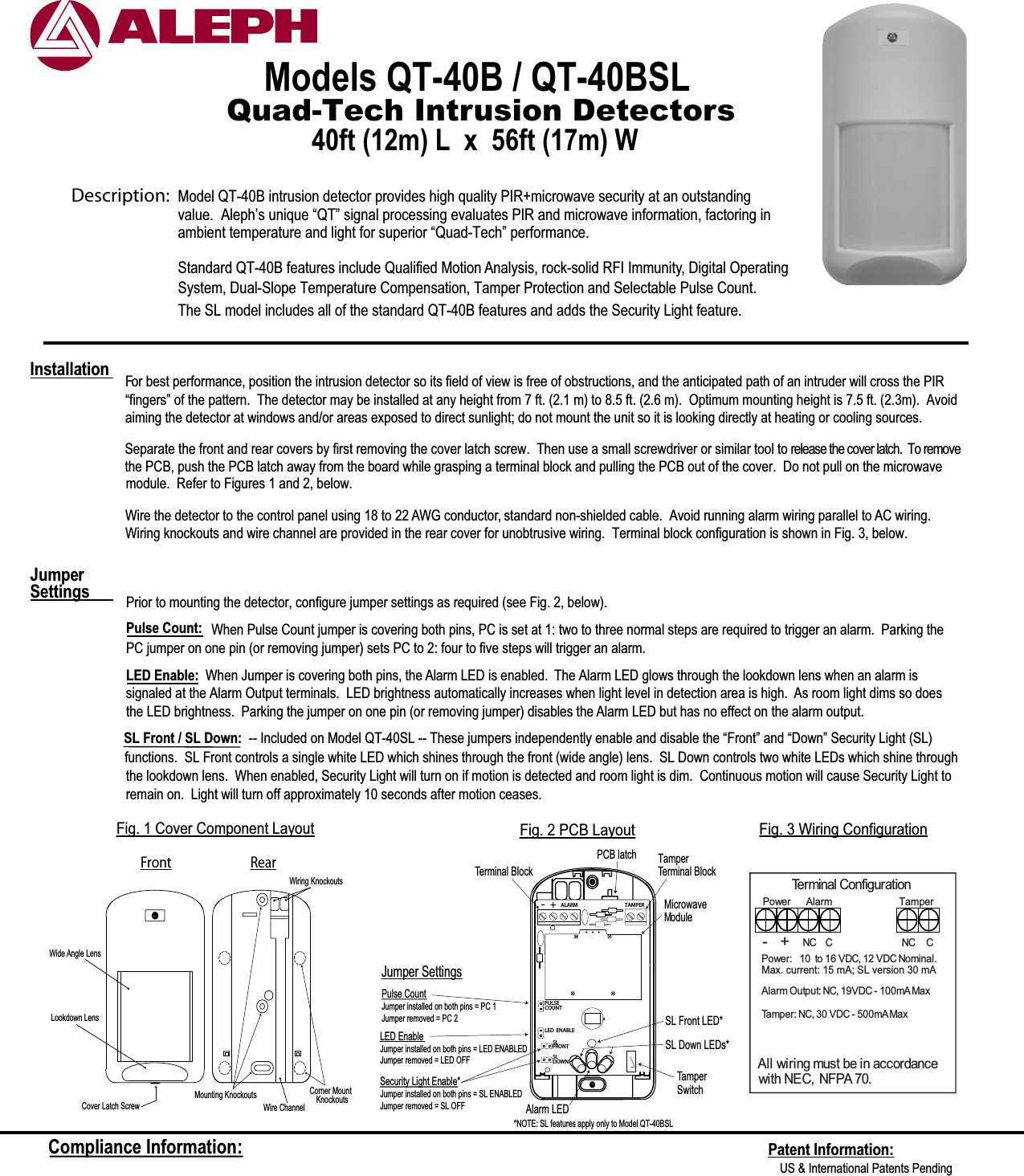
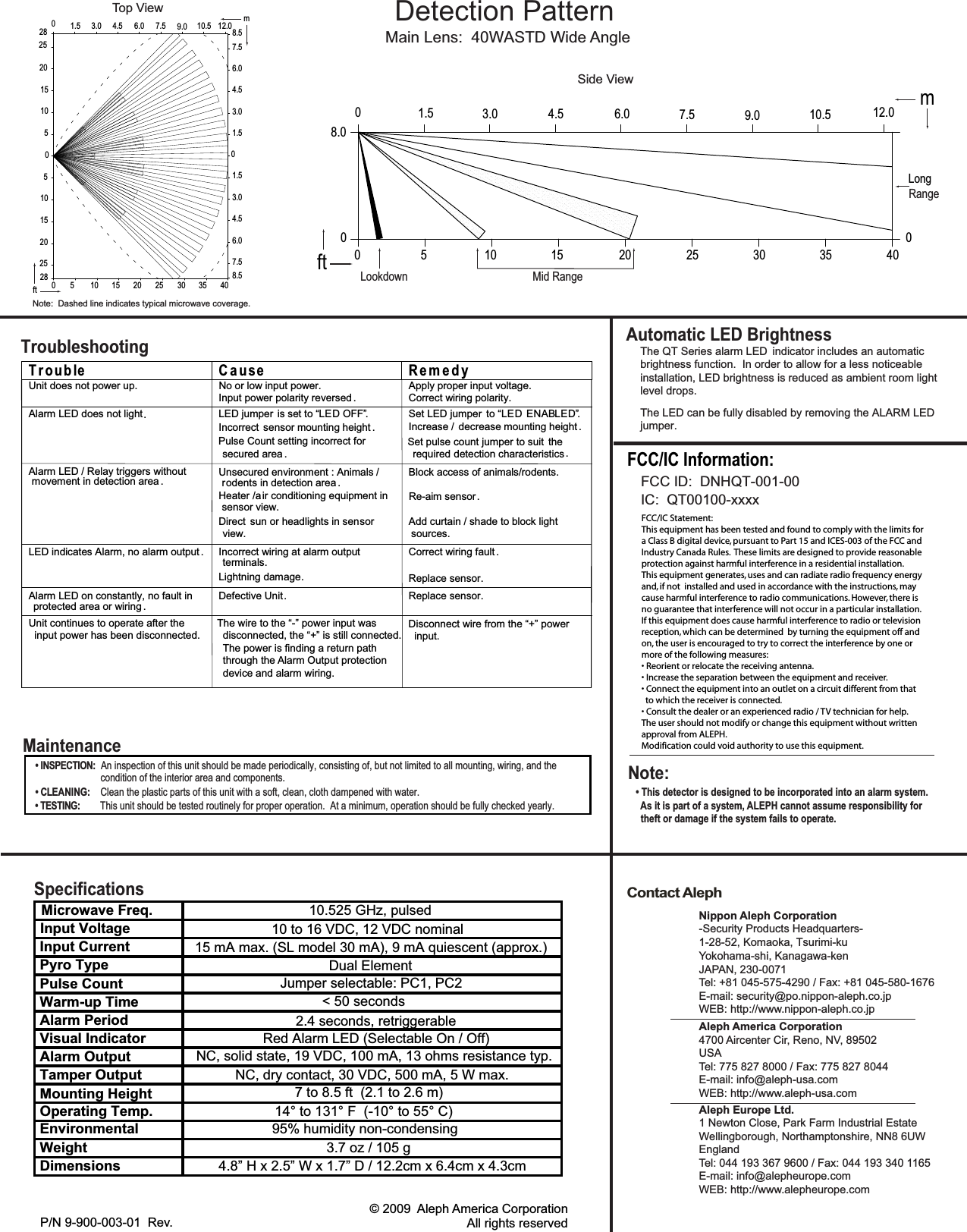
Aleph America QT-001-00 Field Disturbance Sensor User Manual II QT 40B withFCC

Aleph America Corporation Field Disturbance Sensor II QT 40B withFCC

Contents

Installation Manual

Quad-Tech Intrusion DetectorsModels QT-40B / QT-40BSL 40ft (12m) L  x  56ft (17m) W For best performance, position the intrusion detector so its field of view is free of obstructions, and the anticipated path of an intruder will cross the PIR  “fingers” of the pattern.  The detector may be installed at any height from 7 ft. (2.1 m) to 8.5 ft. (2.6 m).  Optimum mounting height is 7.5 ft. (2.3m).  Avoidaiming the detector at windows and/or areas exposed to direct sunlight; do not mount the unit so it is looking directly at heating or cooling sources.  Wire the detector to the control panel using 18 to 22 AWG conductor, standard non-shielded cable.  Avoid running alarm wiring parallel to AC wiring. Wiring knockouts and wire channel are provided in the rear cover for unobtrusive wiring.  Terminal block configuration is shown in Fig. 3, below.Prior to mounting the detector, configure jumper settings as required (see Fig. 2, below).Pulse Count: When Pulse Count jumper is covering both pins, PC is set at 1: two to three normal steps are required to trigger an alarm.  Parking thePC jumper on one pin (or removing jumper) sets PC to 2: four to five steps will trigger an alarm. LED Enable:  When Jumper is covering both pins, the Alarm LED is enabled.  The Alarm LED glows through the lookdown lens when an alarm issignaled at the Alarm Output terminals.  LED brightness automatically increases when light level in detection area is high.  As room light dims so does the LED brightness.  Parking the jumper on one pin (or removing jumper) disables the Alarm LED but has no effect on the alarm output.Jumper SettingsInstallationFront RearWiring KnockoutsCorner Mount    KnockoutsWire ChannelCover Latch ScrewLookdown LensMounting KnockoutsWide Angle LensFig. 1 Cover Component LayoutTerminal ConfigurationNC  CPower:   1  0 to 16 VDC, 12 VDC Nominal.Max. current: 15 mA; SL version 30 mAAlarm Output: NC, 19VDC - 100mAMaxTamper: NC, 30 VDC - 500mAMaxAll wiring must be in accordancewith NEC, NFPA 70.Power Alarm      TamperNC C- +Fig. 3 Wiring ConfigurationFig. 2 PCB LayoutCompliance Information: Patent Information:US & International Patents Pending Description:  Model QT-40B intrusion detector provides high quality PIR+microwave security at an outstanding Standard QT-40B features include Qualified Motion Analysis, rock-solid RFI Immunity, Digital OperatingSystem, Dual-Slope Temperature Compensation, Tamper Protection and Selectable Pulse Count.  ambient temperature and light for superior “Quad-Tech” performance.value.  Aleph’s unique “QT” signal processing evaluates PIR and microwave information, factoring inSeparate the front and rear covers by first removing the cover latch screw.  Then use a small screwdriver or similar tool to release the cover latch.  To removethe PCB, push the PCB latch away from the board while grasping a terminal block and pulling the PCB out of the cover.  Do not pull on the microwavemodule.  Refer to Figures 1 and 2, below.The SL model includes all of the standard QT-40B features and adds the Security Light feature.  SL Front / SL Down: -- Included on Model QT-40SL -- These jumpers independently enable and disable the “Front” and “Down” Security Light (SL)functions.  SL Front controls a single white LED which shines through the front (wide angle) lens.  SL Down controls two white LEDs which shine throughJumper SettingsLED EnableJumper installed on both pins = LED ENABLEDJumper removed = LED OFFPulse CountJumper installed on both pins = PC 1Jumper removed = PC 2TamperTerminal BlockTamper SwitchTamper Terminal BlockALARM TAMPERLED ENABLEPULSECOUNTAlarm LEDPCB latch-+SLFRONTSLDOWNSecurity Light Enable*Jumper installed on both pins = SL ENABLEDJumper removed = SL OFFMicrowave ModuleSL Front LED*SL Down LEDs*the lookdown lens.  When enabled, Security Light will turn on if motion is detected and room light is dim.  Continuous motion will cause Security Light to*NOTE: SL features apply only to Model QT-40BSLremain on.  Light will turn off approximately 10 seconds after motion ceases.
Contact AlephAutomatic LED BrightnessNippon Aleph Corporation-Security Products Headquarters-1-28-52, Komaoka, Tsurimi-kuYokohama-shi, Kanagawa-kenJAPAN, 230-0071Tel: +81 045-575-4290 / Fax: +81 045-580-1676E-mail: security@po.nippon-aleph.co.jpWEB: http://www.nippon-aleph.co.jpAleph America Corporation4700 Aircenter Cir, Reno, NV, 89502 USATel: 775 827 8000 / Fax: 775 827 8044E-mail: info@aleph-usa.comWEB: http://www.aleph-usa.comAleph Europe Ltd.1 Newton Close, Park Farm Industrial EstateWellingborough, Northamptonshire, NN8 6UWEnglandTel: 044 193 367 9600 / Fax: 044 193 340 1165E-mail: info@alepheurope.comWEB: http://www.alepheurope.comMain Lens:  40WASTD Wide AngleDetection PatternThe QT Series alarm LED  indicator includes an automatic brightness function.  In order to allow for a less noticeable installation, LED brightness is reduced as ambient room light level drops.The LED can be fully disabled by removing the ALARM LEDP/N 9-900-003-01  Rev.                   © 2009  Aleph America CorporationAll rights reservedMaintenance• INSPECTION:  An inspection of this unit should be made periodically, consisting of, but not limited to all mounting, wiring, and the• CLEANING:    Clean the plastic parts of this unit with a soft, clean, cloth dampened with water. • TESTING:        This unit should be tested routinely for proper operation.  At a minimum, operation should be fully checked yearly.condition of the interior area and components.             Side ViewLookdown Mid RangeRange8.001.5 3.0 4.5 6.0 7.5 9.0 10.5 12.0 m0 5 10 15 20 25 30 35 400ft0Long            Top View4.53.01.506.0 7.5 9.0 10.5 12.07.520 6.04.58.53.01.501.53.04.56.07.58.5m252815105051015202528 0 5 10 15 20 25 30 35 40ftjumper.Note:  Dashed line indicates typical microwave coverage.T r oub le C a u se R e m e d yUnit does not power up. No or low input power.Input power polarity reversed .Apply proper input voltage.Correct wiring polarity.Alarm LED does not light   LED jumper is set to “ OFF”Incorrect sensor mounting height .Pulse Count setting incorrect forsecured area .Set LED jumper to “ EN ”Increase / decrease mounting height .Set pulse count jumper to suit  therequired detection characteristicsAlarm LED / Relay triggers withoutmovement in detection area . Unsecured environment : Animals /rodents in detection area .Heater /air conditioning equipment insensor view.Direct sun or headlights in sensorview.Block access of animals/rodents.Re-aim sensorAdd curtain / shade to block lightsources.LED indicates Alarm, no alarm output Incorrect wiring at alarm outputterminals.Lightning damageCorrect wiring fault .Replace sensor.Alarm LED on constantly, no fault inprotected area or wiring ..rosnesecalpeRtinUevitcefeDTroubleshooting........DELDELDEL ABUnit continues to operate after the  input power has been disconnected.The wire to the “-” power input was  disconnected, the “+” is still connected.  The power is finding a return path  through the Alarm Output protection  device and alarm wiring.Disconnect wire from the “+” power  input.Input Voltage2.4 seconds, retriggerable15 mA max. (SL model 30 mA), 9 mA quiescent (approx.)Specifications10 to 16 VDC, 12 VDC nominalDual ElementJumper selectable: PC1, PC2< 50 secondsRed Alarm LED (Selectable On / Off)NC, solid state, 19 VDC, 100 mA, 13 ohms resistance typ.NC, dry contact, 30 VDC, 500 mA, 5 W max.7 to 8.5 ft  (2.1 to 2.6 m)14° to 131° F  (-10° to 55° C)95% humidity non-condensing4.8” H x 2.5” W x 1.7” D / 12.2cm x 6.4cm x 4.3cm3.7 oz / 105 gInput CurrentPyro TypePulse CountWarm-up TimeAlarm PeriodVisual IndicatorAlarm OutputTamper OutputMounting HeightOperating Temp.EnvironmentalWeightDimensionsMicrowave Freq.10.525 GHz, pulsedNote:• This detector is designed to be incorporated into an alarm system.  As it is part of a system, ALEPH cannot assume responsibility for  theft or damage if the system fails to operate.FCC/IC Statement:This equipment has been tested and found to comply with the limits fora Class B digital device, pursuant to Part 15 and ICES-003 of the FCC andIndustry Canada Rules.  These limits are designed to provide reasonableprotection against harmful interference in a residential installation. This equipment generates, uses and can radiate radio frequency energyand, if not  installed and used in accordance with the instructions, may cause harmful interference to radio communications. However, there isno guarantee that interference will not occur in a particular installation.If this equipment does cause harmful interference to radio or televisionreception, which can be determined  by turning the equipment off andon, the user is encouraged to try to correct the interference by one ormore of the following measures:• Reorient or relocate the receiving antenna.• Increase the separation between the equipment and receiver.• Connect the equipment into an outlet on a circuit different from that  to which the receiver is connected.• Consult the dealer or an experienced radio / TV technician for help.The user should not modify or change this equipment without writtenapproval from ALEPH.Modification could void authority to use this equipment.FCC ID:  DNHQT-001-00IC:  QT00100-xxxxFCC/IC Information:

Navigation menu