Alereon AL5621 AL5621 PCB RADIO MODULE User Manual UG AL5621 EVB Rev2 0
Alereon, Inc AL5621 PCB RADIO MODULE UG AL5621 EVB Rev2 0
UserManual.wiki
>
Alereon
>
AL5621 User Manual
Users Guide
Navigation menu
Upload a User Manual
Namespaces
Wiki Guide
HTML
PDF
Info
Views
User Manual
Discussion / Help
Navigation
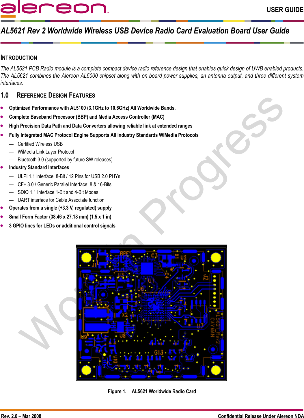
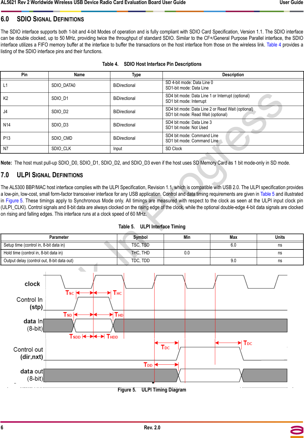
![AL5621 Rev 2 Worldwide Wireless USB Device Radio Card Evaluation Board User Guide User Guide4Rev. 2.04.0 DESIGN CONSIDERATIONS4.1 PowerOne +3.3 V power supply at max data rate average current of 500 mA with peak at 750 mA.4.2 Board ResetDuring power up, an "on board" power monitor holds the board Reset for approximately 150 ms. The card can also be reset at any time by asserting the"Card_Reset#" signal low.It is also important to note that the Mode Pins HSTIF_SEL_0 & HSTIF_SEL_1 are sampled on the rising edge of Card_Reset#.4.3 Mode SwitchingDuring Power-Up, the HSTIF_SEL pins are sampled to configure the AL5300 HSTIF pins to one of three different host interface operating modes. TheHSTIF_SEL pins must remain static for the duration of the operation of the AL5300 BBP/MAC.Table 1 shows the proper settings of the HSTIF_SEL pins.4.4 Firmware Boot-UpAfter completing the power-up cycle and after Card_Reset# is de-asserted, the AL5300 BBP/MAC automatically loads the Executable and Linking Format(ELF) firmware image into the chip’s internal instruction memory. There are two boot modes, SPI and HOST. When utilizing SPI boot mode, the ELF imageis loaded from an external EEPROM, which is connected to the AL5300 BBP/MAC using an industry standard 4-wire SPI port. When utilizing HOST bootmode, the ELF image is loaded directly over the HSTIF through either CF+, SDIO, or ULPI, and eliminates the need for an external EEPROM. Once the ELFimage has been loaded, the AL5300 BBP/MAC will provide a software handshake to the Alereon software drivers indicating that the AL5300 BBP/MAC isready for normal operation. The state of the HOST_BOOT pin determines which of two modes is used (refer to Table 2).5.0 CF+ SIGNAL DEFINITIONSThe CF+/General Purpose Parallel interface can be configured as either a 8-bit or 16-bit parallel data port. The AL5300 BBP/MAC utilities a FIFO memorybuffer at the interface, allowing for simple and efficient high throughput data transfers without affecting the operation of the wireless link. The CF+/GeneralPurpose Parallel interface can be configured and used in accordance to the CF+ specification (CompactFlash, Revision 3.0). When used as a CF+ port, theinterface is compatible to both the I/O and Memory modes of operation.The features of the AL5300 BBP/MAC CF+/General Purpose Parallel interface include:• Interrupt-driven interface (the AL5300 BBP/MAC will interrupt the host system)• 10 registers used to distinguish data and control spaces• Payload data is ordered by a FIFO and is pushed or pulled through a single address• Data and control registers can be accessed either as a 8-bit or 16-bit data wordTable 3 provides a listing of the CF+ interface pins and their functions.Table 1. HSTIF_SEL Pin SettingsHost Interface Mode HSTIF_SEL[1:0]*CF+/ Generic Parallel 00SDIO 01ULPI 10Reserved 11*Note: Please connect the HSTIF_SEL pins to GND for a “0” or do not connect them for a “1”. Both HSTIF_SEL signals are pulled high on the daughter board through a 10K resistor to VDD. 0 = GND; 1 = No-Connect.Table 2. Boot ModesBoot Mode HOST_BOOT*SPI Boot Mode 0Host Boot Mode 1*Note: Please connect HOST_BOOT through a 330 Ω resistor to GND for “0” or No-Connect for “1”. 0 = 330 Ω to GND; 1 = No-Connect.](https://usermanual.wiki/Alereon/AL5621/User-Guide-953292-Page-4.png)
![User Guide AL5621 Rev 2 Worldwide Wireless USB Device Radio Card Evaluation Board User GuideRev. 2.0 5Table 3. CF+/General Purpose Parallel Interface Pin Descriptions AL5300 Pin Name Type DescriptionP8, P7, P6, P5, L5, P4, N4, N3, P1, N1, L2 ADDR[10:0] InputMemory Mode: These address lines along with the CF_REG# signal are used to select the following: The I/O port address registers within the generic parallel interface/CF+ Card, the memory mapped port address registers within the generic parallel interface/CF+ Card, a byte in the card's information structure and its configuration control and status registers.IO Mode: This signal is the same as the Memory Mode signal.L10, N11, N12, N13, P14, J1, J2, K1, P10, P11, P12, P13, N14, J4, K2, L1DATA[15:0]Bi-DirectionalMemory Mode: These lines carry the Data, Commands and Status information between the host and the controller. DATA0 is the Least Significant Bit (LSB) of the Even Byte of the Word. DATA8 is the LSB of the Odd Byte of the Word.Note: When operating in 8 bit mode, DATA[15:8] are ignored.IO Mode: This signal is the same as the Memory Mode signal.P3 CF_RESET InputMemory Mode*: The generic parallel interface/CF+ Card is Reset when the RESET pin is high with the following important exception: The host may leave the RESET pin open or keep it continually high from the application of power without causing a continuous Reset of the card. Under either of these conditions, the card shall emerge from power-up having completed an initial Reset.The generic parallel interface/CF+ Card is also Reset when the Soft Reset bit in the Card Configuration Option Register is set.IO Mode*: This signal is the same as the Memory Mode signal.*Note: CF_RESET is used to reset the CF+/General Purpose Parallel ports controller independently of the AL5300 BBP/MAC. Asserting CF_RESET will NOT reset the AL5300 BBP/MAC.P9 CF_CE1# InputMemory Mode: These input signals are used both to select the card and to indicate to the card whether a byte or a word operation is being performed. CF_CE2# always accesses the odd byte of the word. CF_CE1# accesses the even byte or the Odd byte of the word depending on ADDR0 and CF_CE2#.IO Mode: This signal is the same as the Memory Mode signal.N9 CF_CE2# InputMemory Mode: These input signals are used both to select the card and to indicate to the card whether a byte or a word operation is being performed. CF_CE2# always accesses the odd byte of the word. CF_CE1# accesses the even byte or the Odd byte of the word depending on ADDR0 and CF_CE2#.IO Mode: This signal is the same as the Memory Mode signal.N8 CF_OE# InputMemory Mode: This is an Output Enable strobe generated by the host interface. It is used to read data from the generic parallel interface/CF+ Card in Memory Mode and to read the CIS and configuration registers.IO Mode: In I/O Mode, this signal is used to read the CIS and configuration registers.L6 CF_WE# InputMemory Mode: This is a signal driven by the host and used for strobing memory write data to the registers of the generic parallel interface/CF+ Card when the card is configured in the memory interface mode. It is also used for writing the configuration registers.IO Mode: In I/O Mode, this signal is used for writing the configuration registers.N5 CF_IREQ# OutputMemory Mode: In Memory Mode, this signal is set high when the generic parallel interface/CF+ Card is ready to accept a new data transfer operation and is held low when the card is busy. At power up and at Reset, the CF_IREQ# signal is held low (busy) until the generic parallel interface/CF+ Card has completed its power up or reset function. No access of any type should be made to the generic parallel interface/CF+ Card during this time.Note, however, that when a card is powered up and used with CF_IREQ# continuously disconnected or asserted, the Reset function of the CF_IREQ# pin is disabled. Consequently, the continuous assertion of CF_IREQ# from the application of power shall not cause the READY signal to remain continuously in the busy state.IO Mode: After the generic parallel interface/CF+ Card has been configured for I/O operation, this signal is used as Interrupt Request#. This line is strobed low to generate a pulse mode interrupt or held low for a level mode interrupt.L8 CF_IORD# InputMemory Mode: This signal is not used in this mode.IO Mode: This is an I/O Read strobe generated by the host. This signal gates I/O data onto the bus from the generic parallel interface/CF+ Card when the card is configured to use the I/O interface.N7 CF_IOWR# InputMemory Mode: This signal is not used in this mode.IO Mode: The I/O Write strobe pulse is used to clock I/O data on the bus into the generic parallel interface/CF+ Card controller registers when thickeners parallel interface/CF+ Card is configured to use the I/O interface. The clocking shall occur on the negative to positive edge of the signal (trailing edge).K4 CF_STSCHG# OutputMemory Mode: This signal is asserted high, as BVD1 is not supported.IO Mode: This signal is asserted low to alert the host to changes in the READY and Write Protect states, while the I/O interface is configured. Its use is controlled by the Card Config and Status Register.M1 CF_REG# InputMemory Mode: This signal is used during Memory Cycles to distinguish between Common Memory and Register (Attribute) Memory accesses. High for Common Memory, Low for Attribute Memory.IO Mode: The signal shall also be active (low) during I/O Cycles when the I/O address is on the Bus.N2 CF_INPACK# OutputMemory Mode: This signal is not used in this mode.IO Mode: The Input Acknowledge signal is asserted by the generic parallel interface/CF+ Card when the card is selected and responding to an I/O read cycle at the address that is on the address bus. This signal is used by the host to control the enable of any input data buffers between the generic parallel interface/CF+ Card and the CPU.H1 CF_IOIS16# OutputMemory Mode: The generic parallel interface/CF+ Card does not have a write protect switch. This signal is held low after the completion of the reset initialization sequence.IO Mode: When the generic parallel interface/CF+ Card is configured for I/O Operation, this pin is used for the CF_IOIS16# function. A Low signal indicates that a 16-bit or odd byte only operation can be performed at the addressed port.P2 CF_WAIT# OutputMemory Mode: The CF_WAIT# signal is driven low by the generic parallel interface/CF+ Card to signal the host to delay completion of a memory or I/O cycle that is in progress.IO Mode: This signal is the same as Memory Mode signal.](https://usermanual.wiki/Alereon/AL5621/User-Guide-953292-Page-5.png)