Alien Technology ALR9650 RFID Reader User Manual Hardware Setup Guide
Alien Technology Corporation RFID Reader Hardware Setup Guide
UserManual.wiki
>
Alien Technology
>
ALR9650 User Manual
>
Hardware Setup Guide
Contents
1.
Quick Installation Guide
2.
Hardware Setup Guide
Hardware Setup Guide
Navigation menu
Upload a User Manual
Namespaces
Wiki Guide
HTML
PDF
Info
Views
User Manual
Discussion / Help
Navigation


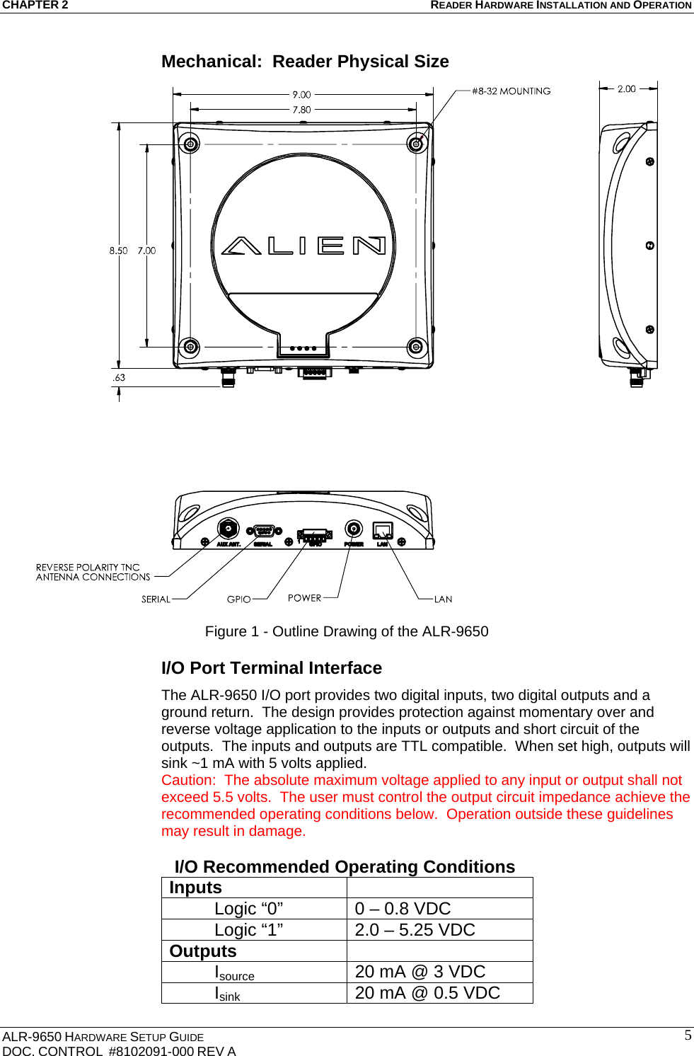
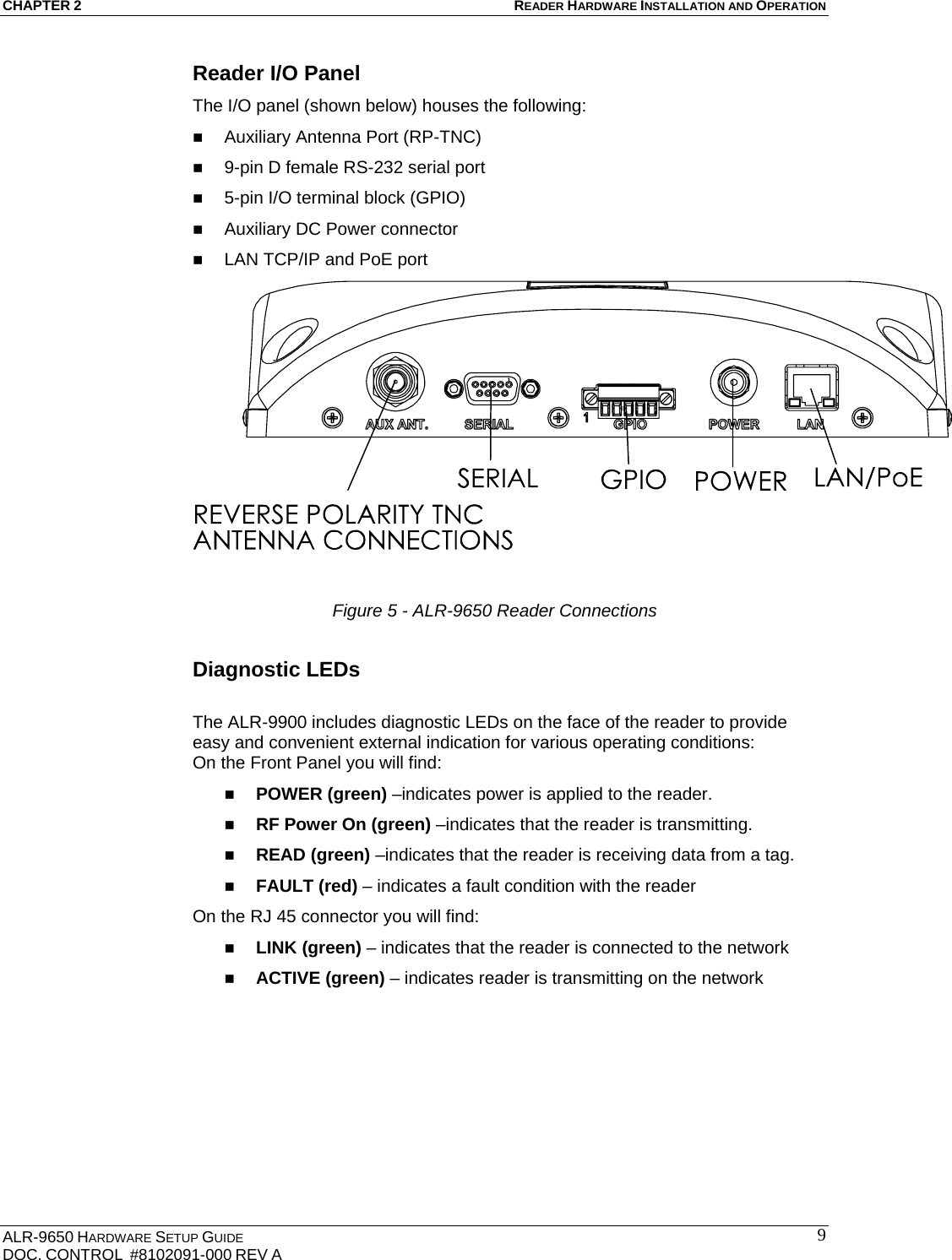
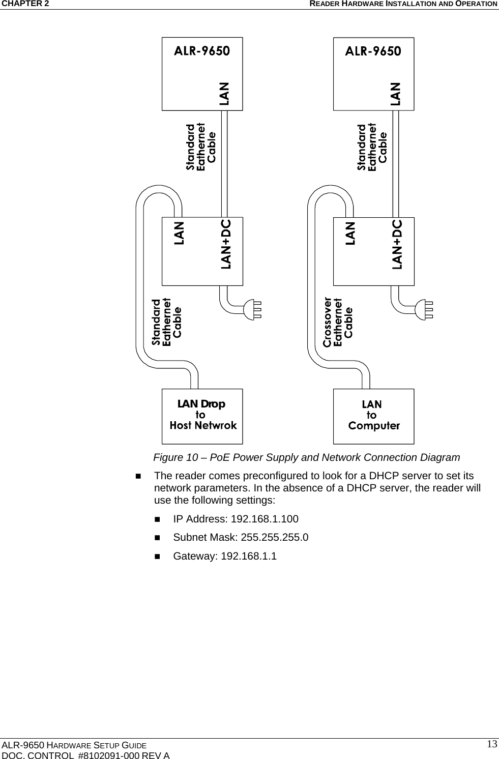
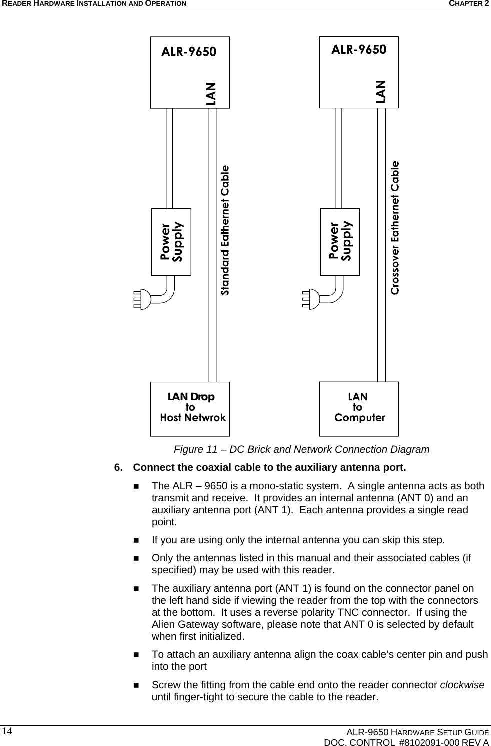
![READER HARDWARE INSTALLATION AND OPERATION CHAPTER 2 ALR-9650 HARDWARE SETUP GUIDE DOC. CONTROL #8102091-000 REV A 18 NOTE: To maintain compliance with FCC regulations, use only antenna cable and power supplies supplied with the unit or approved by Alien Technology for use with the ALR-9650. 2. Select mounting position for reader. The ALR – 9650 has been designed to provide reliable operation over its operating temperature range. This is enhanced by proper mounting of the reader during bench test and installation. When using the reader place it on a solid thermally conductive surface. Optimum thermal performance is achieved by mounting the unit to a metal mounting plate with direct contact between the reader base and the mounting plate. When mounting vertically the connector panel should be oriented at the bottom. When using the auxiliary antenna it should be placed close enough reader to accommodate the cable length without putting strain on the connectors. Be sure power is available at the selected reader location. [really just for PoE] Mount units individually. Do not stack them. 3. Install reader. Secure the reader through the four mounting holes to its mounting location (wall, post, mounting bracket) using appropriate #8 pan head screws at least 1.125” long. 4. Install the auxiliary antenna. Secure the auxiliary antenna (if used) through the mounting holes on either flange to its mounting location using appropriate hardware. 5. Connect the auxiliary antenna to reader. Route coax cable from the auxiliary antenna to the reader according to your system design specifications and secure it properly. Align the connector of the cable with the reader antenna port, push into the port, and finger-tighten the screw fitting. 6. Connect reader power supply. If you are using the PoE power supply use a short standard Ethernet cable to connect the reader RJ – 45 jack to the LAN+DC RJ – 45 jack of the power supply. Align the RJ-45 connector with the corresponding TCP/IP port on the reader or the power supply and push the connector in. If you are using the optional AC/DC power supply connect the DC power jack into the DC power plug of the reader. Tighten the screw fitting finger tight. If you are using an 802.3af compliant network for reader power take no action. DO NOT use both the PoE power supply and the optional AC/DC power brick on the same unit at the same time. DO NOT plug the AC power cord into the supply at this time. 7. Connect reader to the LAN or host PC.](https://usermanual.wiki/Alien-Technology/ALR9650.Hardware-Setup-Guide/User-Guide-890074-Page-22.png)