Alien Technology ALR9800 RFID Reader User Manual Guide Reader Interface
Alien Technology Corporation RFID Reader Guide Reader Interface
UserManual.wiki
>
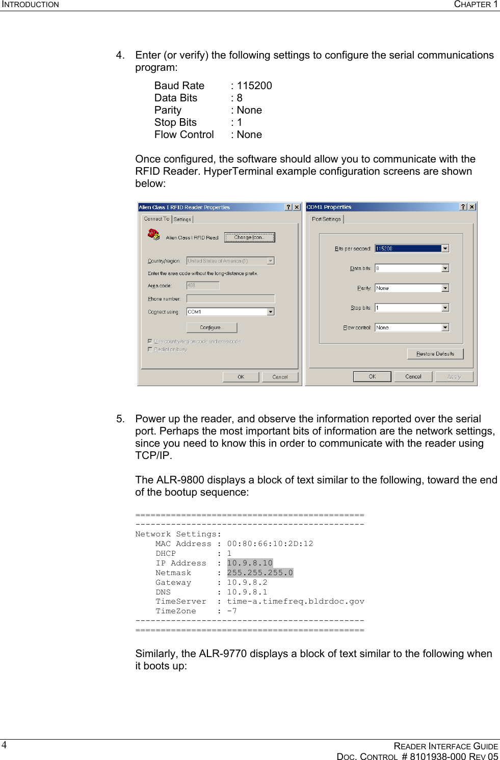
Alien Technology
>
ALR9800 User Manual
>
Manual 3
Contents
1.
Manual 1
2.
Manual 2
3.
Manual 3
Manual 3
Navigation menu
Upload a User Manual
Namespaces
Wiki Guide
HTML
PDF
Info
Views
User Manual
Discussion / Help
Navigation
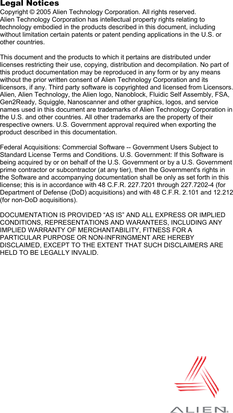
![INTRODUCTION CHAPTER 1 READER INTERFACE GUIDE DOC. CONTROL # 8101938-000 REV 05 2 External files and documents are referenced in italic text. Specific characters and commands to be typed are shown within quotation marks, and/or in fixed-width font. Example: At the prompt type “set DHCP=ON”. Values to be provided and typed in by the user are shown within brackets in upper and lowercase. Example: At the prompt type “set IPaddress=[IP address value]” or “set IPaddress=xxx.xxx.xxx.xxx”. The actual command typed in would appear as: “set IPaddress=10.1.60.5”. Blocks of sample code or commands appear: indented, in a fixed-width serif font. Keys to be pressed are shown in brackets and all caps. Example: Press the [ENTER] key. Upon entering any command instruction, you must press [ENTER] to send the command. RFID Reader commands are not case sensitive. Although, for clarity, the commands may be shown in upper and lower case in this document, you may type them in all lowercase characters, if you prefer. A space is required between the command (verb) such as “get” or “set” and the specific parameters, as in the example “get IPaddress.” However, no space is required between the parameter elements such as “IP” and “address.” Requirements In order to fully interface with the RFID Reader you will need the following: a PC running Windows 98 or higher, with CD-ROM drive and an available RS-232 serial port standard 120 VAC power host software (Alien demo software or your own custom software) RFID Tags (AIDC Class I compliant) Serial communication requires: a text-based serial communications program (such as HyperTerminal) running on any computer Ethernet communication requires: an Ethernet network a Telnet communication program](https://usermanual.wiki/Alien-Technology/ALR9800.Manual-3/User-Guide-583957-Page-10.png)
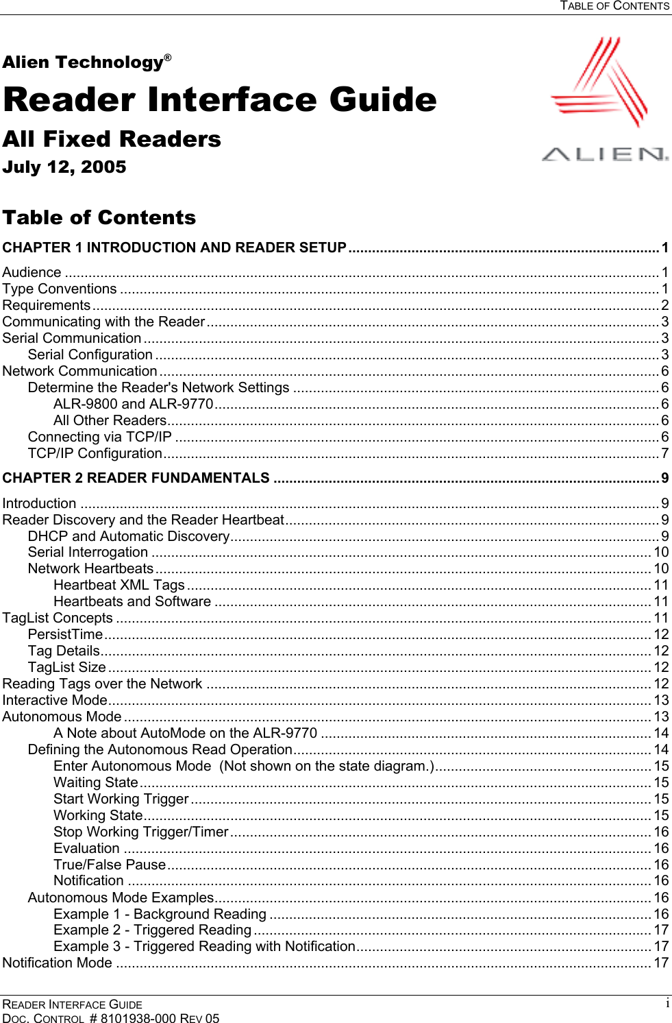
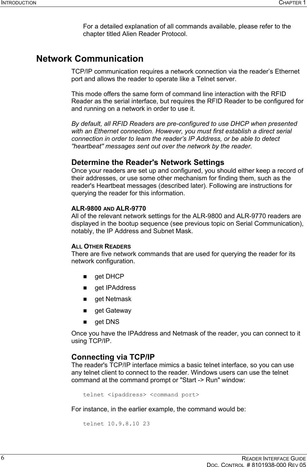
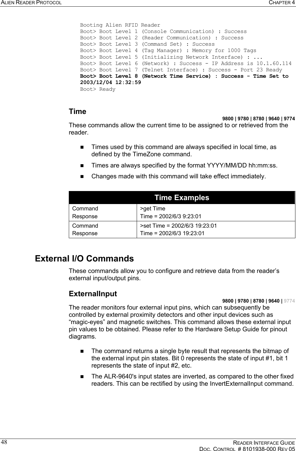
![CHAPTER 1 INTRODUCTION READER INTERFACE GUIDE DOC. CONTROL # 8101938-000 REV 05 5ixp1 Link encap:Ethernet HWaddr 00:0A:55:00:01:10 inet addr:10.9.8.10 Bcast:10.255.255.255 Mask:255.255.255.0 UP BROADCAST RUNNING MULTICAST MTU:1500 Metric:1 RX packets:602 errors:0 dropped:0 overruns:0 frame:0 TX packets:5 errors:0 dropped:0 overruns:0 carrier:0 collisions:0 txqueuelen:256 For all other readers, the bootup trace displays text such as the following: Boot> Booting Alien RFID Reader Boot> Boot Level 1 (Console Communication) : Success Boot> Boot Level 2 (Reader Communication) : Success Boot> Boot Level 3 (Command Set) : Success Boot> Boot Level 4 (Tag Manager) : Memory for 1000 Tags Boot> Boot Level 5 (Initializing Network Interface) : ... Boot> Boot Level 6 (Network) : Success - IP Address is 10.9.8.10 Boot> Boot Level 7 (Telnet Interface) : Success - Port 23 Ready Both traces indicate that the reader can be contacted over TCP/IP at the address 10.9.8.10, on port 23. 6. If your reader supports the Alien Reader Protocol over serial the serial interface, you will see the "Alien >" command prompt. At the command prompt, you may now type any command followed by the [ENTER] key to submit the command. The following basic commands are helpful in verifying the reader-host interface: • "Help" (or “h”) – provides a list of all commands available • "Info" (or “i”) – provides a list of current settings for the reader • "get TagList" (or "t") – scans field immediately for tags and reports the results NOTE: RFID Reader commands are case insensitive and may be typed in all lowercase characters, if preferred.](https://usermanual.wiki/Alien-Technology/ALR9800.Manual-3/User-Guide-583957-Page-13.png)
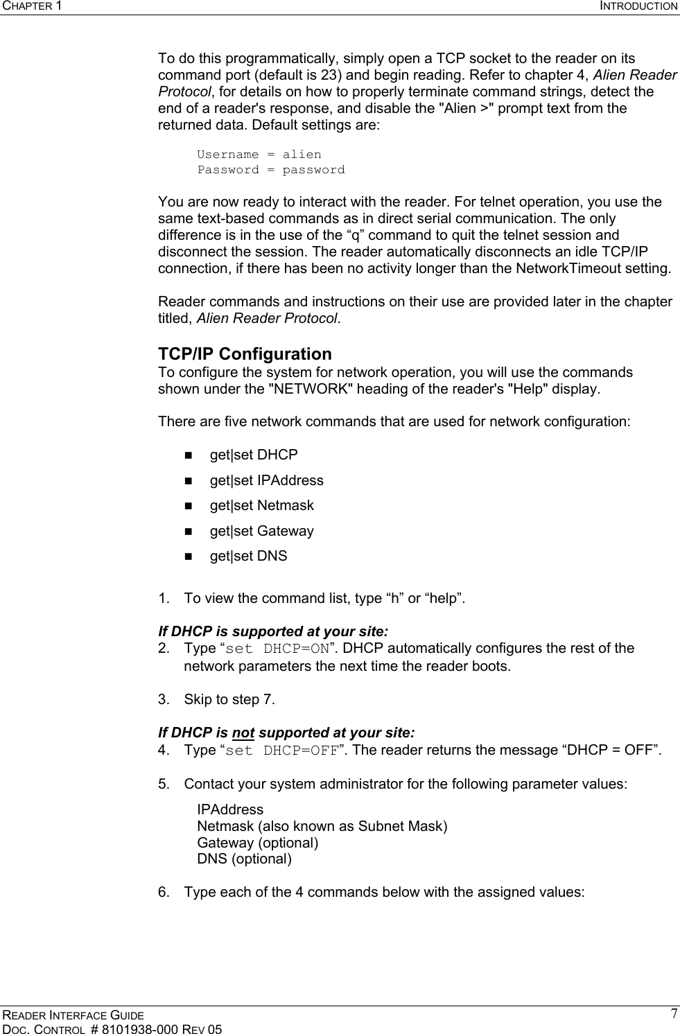
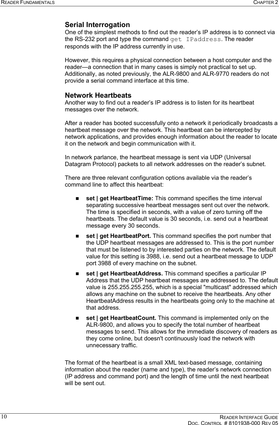
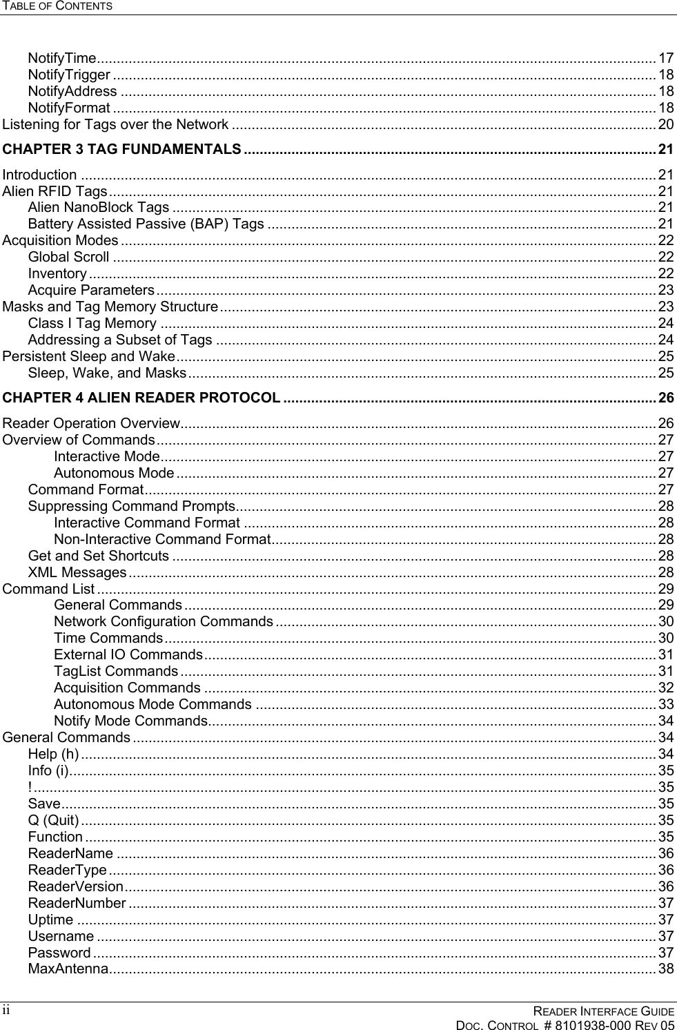
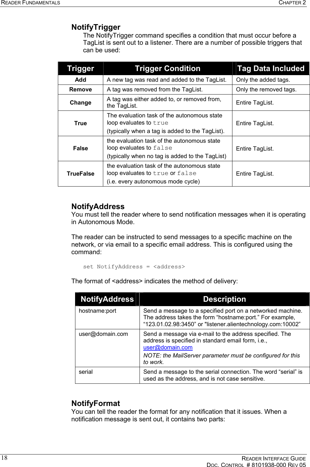
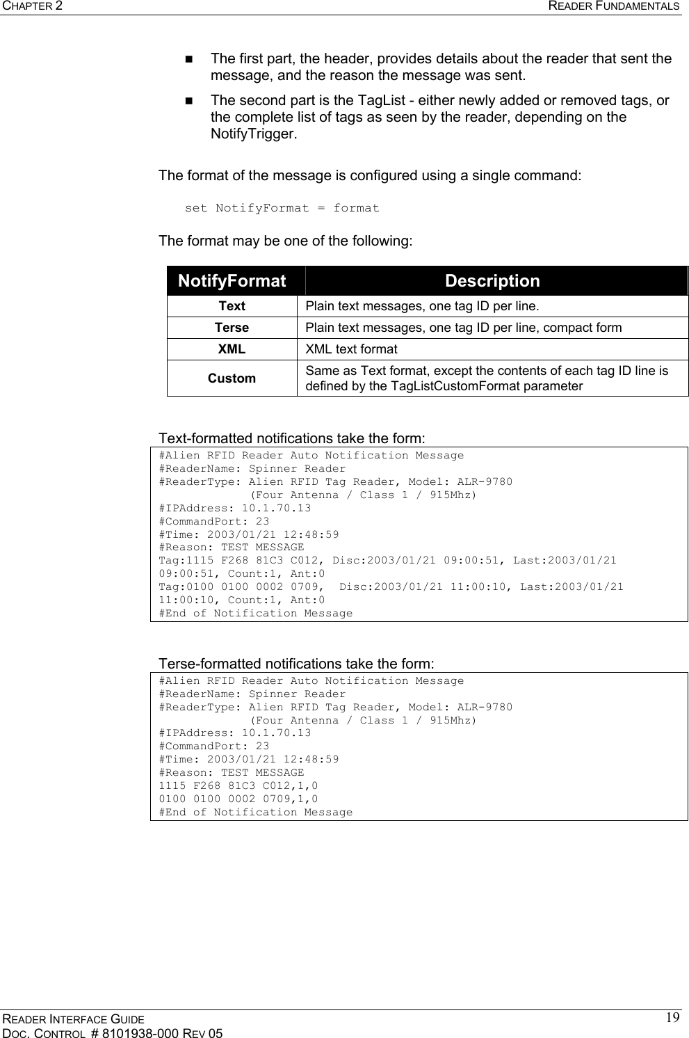
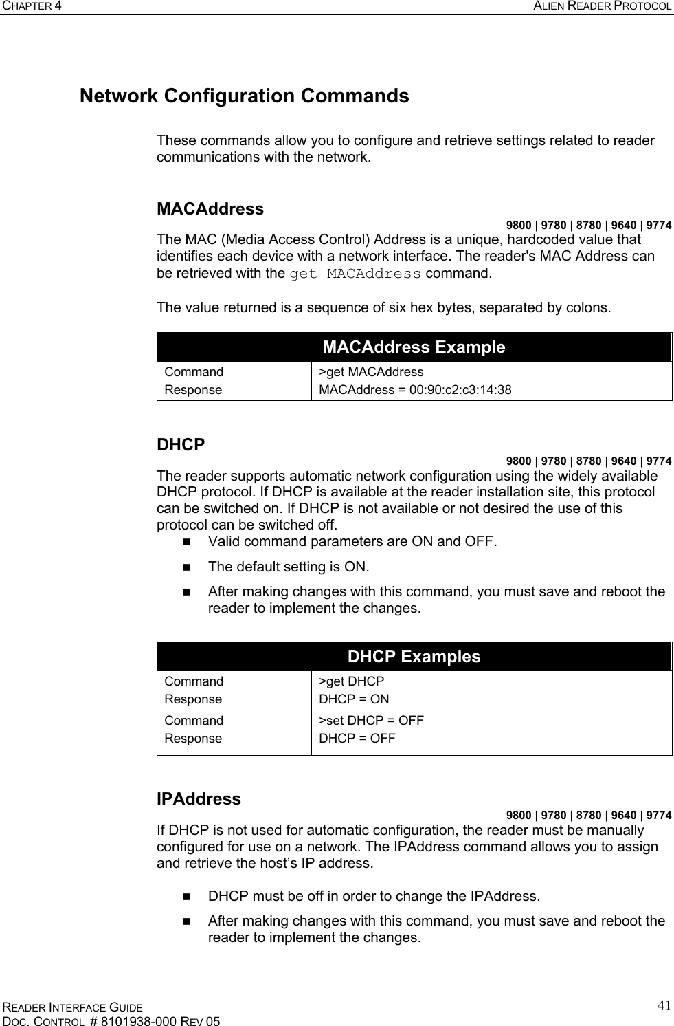
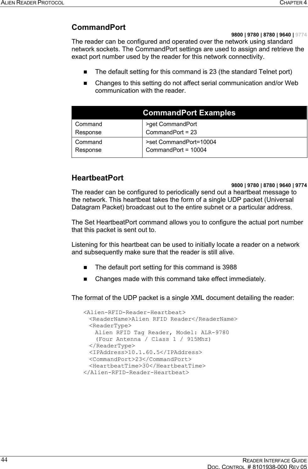
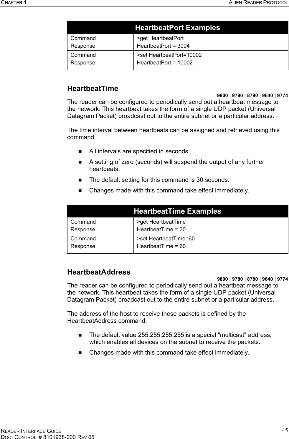
![CHAPTER 2 READER FUNDAMENTALS READER INTERFACE GUIDE DOC. CONTROL # 8101938-000 REV 05 11<Alien-RFID-Reader-Heartbeat> <ReaderName>Alien RFID Reader</ReaderName> <ReaderType> Alien RFID Tag Reader, Model: ALR-9780 (Four Antenna / EPC Class 1 / 915 Mhz) </ReaderType> <IPAddress>10.1.60.5</IPAddress> <CommandPort>23</CommandPort> <HeartbeatTime>30</HeartbeatTime> <MACAddress>01:02:03:04:05:06</MACAddress> </Alien-RFID-Reader-Heartbeat> HEARTBEAT XML TAGS ReaderName is the user-defined name associated with the reader. This name can be set by a user to help identify which reader is which. For example, multiple readers in a warehouse may be named “loading bay 1”, “loading bay 2” etc., thus providing a clear indication as to the physical location of the reader. ReaderType details the specific type of reader sending out the heartbeat. This information is hard-coded into the reader’s firmware and is not user-configurable. IPAddress and CommandPort elements detail the location of the reader on the network. The IP address is simply the network address of the reader. The command port is the port number on which the reader is listening for incoming user commands. Typically, this is port 23, the standard telnet port, allowing a user to communicate with the reader over the network by typing “telnet [IPAddress]” into the command line of most computers. HeartbeatTime is the time until the next heartbeat. This time (in seconds) enables any application software to detect when a reader is powered-down or the network connection breaks; if a new heartbeat is not received after the expected time elapses, then such an interruption to normal service can be detected. MACAddress gives the unique identifier assigned to the reader's network interface hardware by the manufacturer. It is provided in the ALR-9800 and ALR-9774 heartbeat messages only. HEARTBEATS AND SOFTWARE The RFID Developer’s Kit CD that may accompany the reader provides source code and software libraries to listen for these network heartbeats, in the Java, .NET, and Visual Basic languages. The Alien RFID Gateway application, bundled with all readers, uses the Java version of these libraries to build its active reader list on the main screen. The latest Gateway version at the time of this writing is v2.14.13. Alien recommends users download the install the latest version of Gateway software. TagList Concepts During normal operation, the reader always has a concept of "what's out there" by maintaining an internal list of the tags that are active. Active tags are those read by the reader at least once within a predefined interval. Any new tags presented to the reader are added to the list, and any tags that have not been seen for a period of time (the PersistTime) are removed from the list.](https://usermanual.wiki/Alien-Technology/ALR9800.Manual-3/User-Guide-583957-Page-19.png)
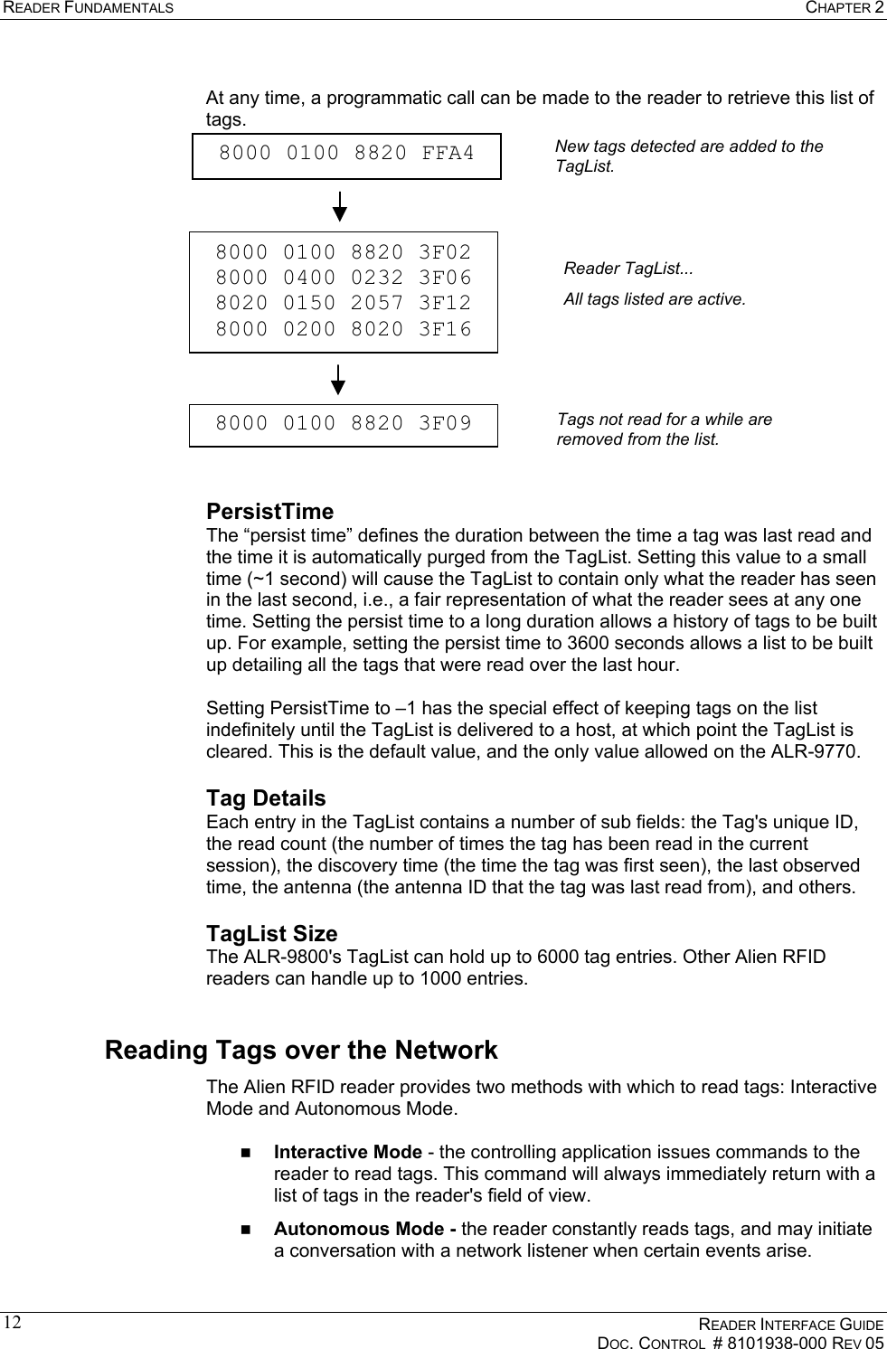
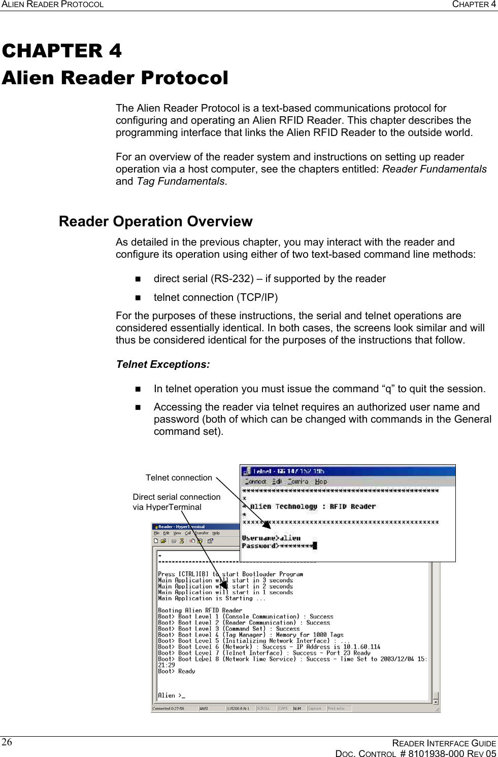
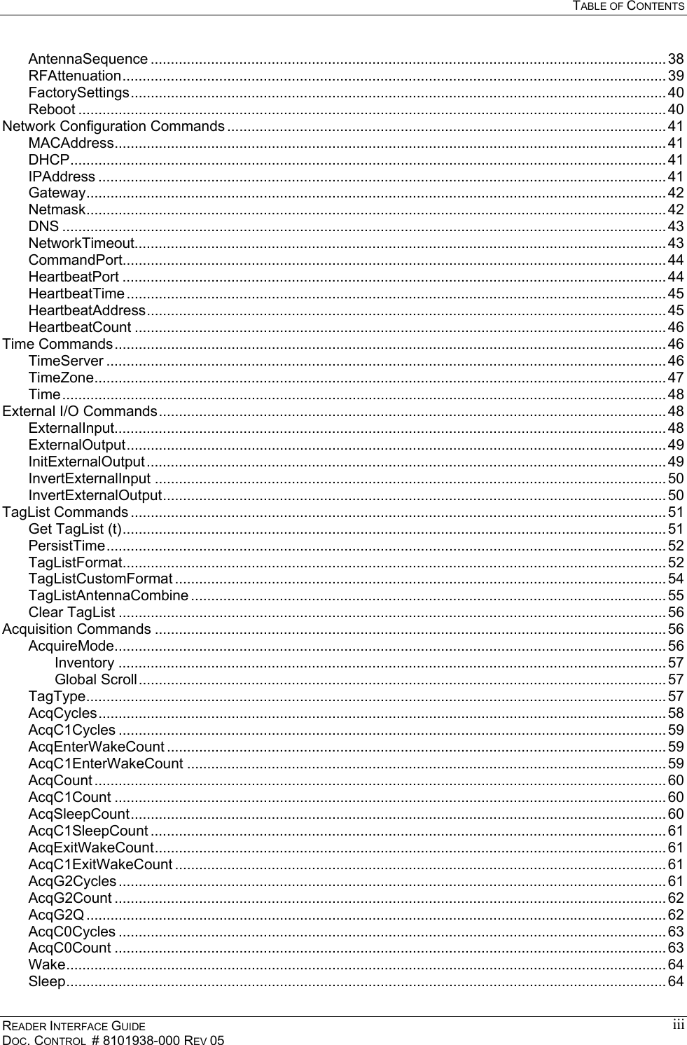
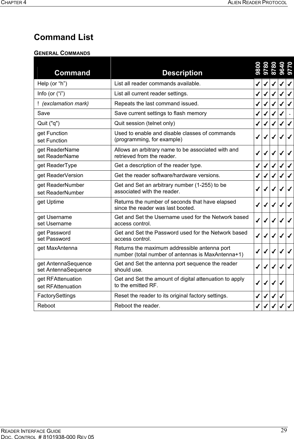
![CHAPTER 4 ALIEN READER PROTOCOL READER INTERFACE GUIDE DOC. CONTROL # 8101938-000 REV 05 27Overview of Commands There are two distinct categories of reader activities: those initiated by the host (Interactive Mode), and those initiated by the reader itself (Autonomous Mode). INTERACTIVE MODE Interactive Mode activities are initiated by a program or user who issues commands to the reader from a separate host computer. The host always initiates the transaction with a request, and the reader responds with an immediate reply. The host should wait for a reply before initiating another command. Interactive commands are used to configure and operate the reader, as well as to interrogate tags and retrieve the stored TagList on demand. AUTONOMOUS MODE Autonomous Mode activities instruct the reader to perform certain tasks without outside intervention, according to conditions set by the programmer. These commands typically tell the reader to read tags based on trigger events (external digital inputs or internal timers) and then send notification messages to a host system, depending on various TagList-based triggers. For example, the reader can be instructed to search the field until it sees a tag, then to read the new tag and e-mail the event to a specified e-mail address. Command Format All commands between the host system and the reader are human readable, ASCII text-based messages. For example, a command to set the name of the reader using the "set ReaderName" command takes the form: Alien >set ReaderName = My Alien Reader[CR][LF] All commands to the reader are single-line ASCII strings, terminated by a carriage-return / line-feed pair, written as [CR][LF]. The [CR] character is ASCII code 0x0D, while the [LF] character is ASCII code 0x0A. These characters are sometimes written as "\r" and "\n" respectively. All responses from the reader are either single-line or multi-line ASCII strings, terminated by [CR][LF][0], where [0] is ASCII code 0x00. When a responses is comprised of multiple text lines, each line is separated by a single [CR][LF] sequence. An example of a command and single-line response is: Alien >get ReaderName[CR][LF] ReaderName = Alien Reader[CR][LF][0] An example of a command and multi-line response is: Alien >get ReaderVersion[CR][LF] Ent. SW Rev: 03.00.10 : Jun 08 2004 : 10:54:30[CR][LF] Country Code: 01, Reader Type: 03, Firmware Rev: 2.1.4[CR][LF][0] Commands are not case sensitive: “set readername” is equivalent to “sET ReADerNaME”.](https://usermanual.wiki/Alien-Technology/ALR9800.Manual-3/User-Guide-583957-Page-35.png)
![ALIEN READER PROTOCOL CHAPTER 4 READER INTERFACE GUIDE DOC. CONTROL # 8101938-000 REV 05 28Suppressing Command Prompts By default, the reader responds to all commands using the interactive console-style interface. Consequently replies are always followed by a command prompt indicating that the reader is ready for more user input. Often, the command prompt is not required, especially when client software is written that programmatically communicates with the reader. Since the command prompt is sent after the null-terminated response, this prompt text would be interpreted as the beginning of the next reader response. To accommodate this, command prompts can be suppressed by prepending a 0x01 character, written as [1], to the command string. For example: INTERACTIVE COMMAND FORMAT Alien >get ReaderName[CR][LF] ReaderName = Alien Reader[CR][LF][0] [CR][LF]Alien > NON-INTERACTIVE COMMAND FORMAT [1]get ReaderName[CR][LF] ReaderName = Alien Reader[CR][LF][0] Get and Set Shortcuts As a typing convenience, you may also use the following shortened command syntax: Standard Syntax Shortened Syntax Get <attributeName> <attributeName>? Set <attributeName> = <attributeValue> <attributeName> = <attributeValue> Examples: Alien >get ReaderName ReaderName = Alien RFID Reader Alien >ReaderName? ReaderName = Alien RFID Reader Alien >set ReaderName = Alice ReaderName = Alice Alien >ReaderName = Alice ReaderName = Alice XML Messages There are a few cases where text-based replies and messages are formatted in XML format for easier computer parsing. Complete Document Type Definitions (DTDs) for each XML document are provided in this document as an appendix, as well as on the Developer's Kit CD. The following messages are sent in XML format: Heartbeat Messages Notification Messages (if NotifyFormat = XML) The "get TagList" commands (if TagListFormat = XML)](https://usermanual.wiki/Alien-Technology/ALR9800.Manual-3/User-Guide-583957-Page-36.png)

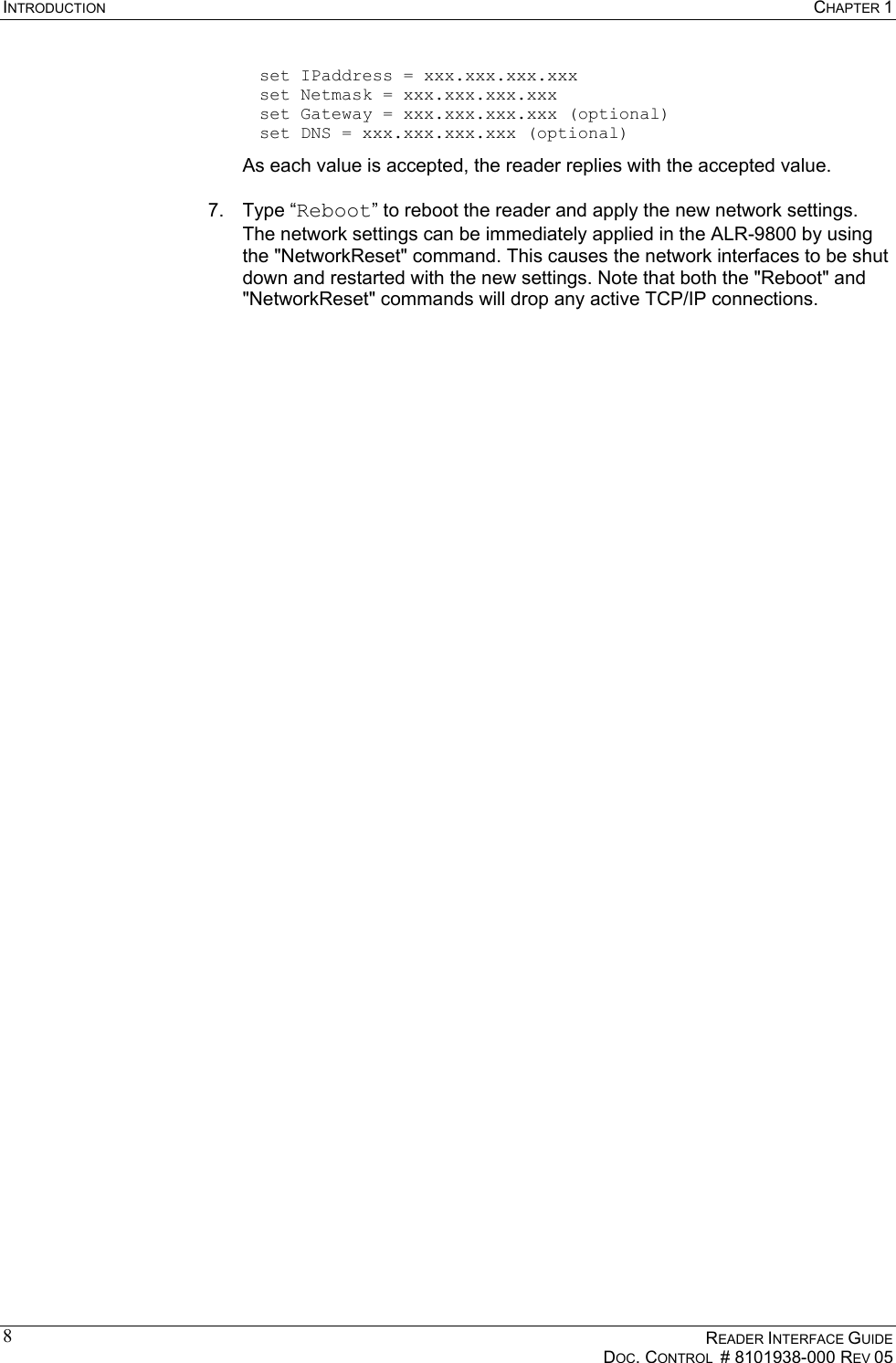
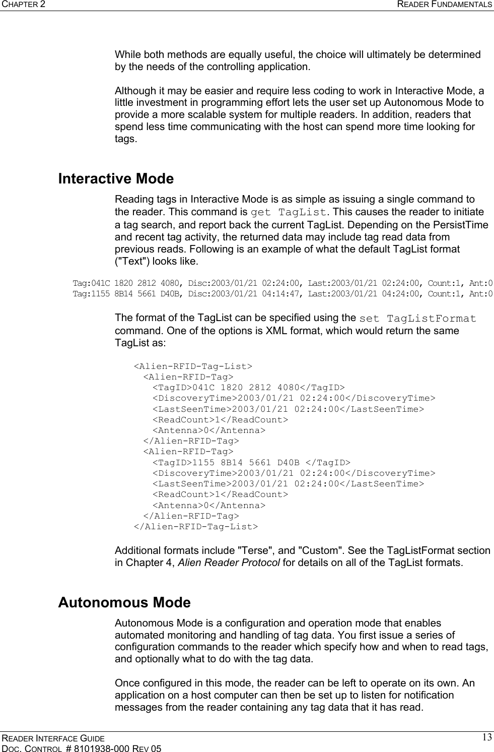
![APPENDIX A DTDS FOR XML DATA STRUCTURES READER INTERFACE GUIDE DOC. CONTROL # 8101938-000 REV 05 93APPENDIX A DTDs for XML Data Structures The reader has the capability to generate three different types of XML-formatted documents. This appendix gives a Document Type Definition (DTD) for each of these XML documents. Heartbeat DTD <?xml version="1.0" encoding="UTF-8"?> <!DOCTYPE Alien-RFID-Reader-Heartbeat [ <!ELEMENT Alien-RFID-Reader-Heartbeat (ReaderName, ReaderType, IPAddress, CommandPort, HeartbeatTime, MACAddress?)> <!ELEMENT ReaderName (#PCDATA)> <!ELEMENT ReaderType (#PCDATA)> <!ELEMENT IPAddress (#PCDATA)> <!ELEMENT CommandPort (#PCDATA)> <!ELEMENT HeartbeatTime (#PCDATA)> <!ELEMENT MACAddress (#PCDATA)> ]> TagList DTD <?xml version="1.0" encoding="UTF-8"?> <!DOCTYPE Alien-RFID-Tag_List [ <!ELEMENT Alien-RFID-Tag_List (Alien-RFID-Tag*)> <!ELEMENT Alien-RFID-Tag (TagID, DiscoveryTime, LastSeenTime, Antenna, ReadCount, Protocol?)> <!ELEMENT TagID (#PCDATA)> <!ELEMENT DiscoveryTime (#PCDATA)> <!ELEMENT LastSeenTime (#PCDATA)> <!ELEMENT Antenna (#PCDATA)> <!ELEMENT ReadCount (#PCDATA)> <!ELEMENT Protocol (#PCDATA)> ]> Notification DTD <?xml version="1.0" encoding="UTF-8"?> <!DOCTYPE Alien-RFID-Reader-Auto-Notification [ <!ELEMENT Alien-RFID-Reader-Auto-Notification (ReaderName, ReaderType, IPAddress, CommandPort, Time, Reason, StartTriggerLines?, StopTriggerLines?, Alien-RFID-Tag-List)> <!ELEMENT ReaderName (#PCDATA)> <!ELEMENT ReaderType (#PCDATA)> <!ELEMENT IPAddress (#PCDATA)> <!ELEMENT CommandPort (#PCDATA)> <!ELEMENT Time (#PCDATA)> <!ELEMENT Reason (#PCDATA)> <!ELEMENT StartTriggerLines (#PCDATA)> <!ELEMENT StopTriggerLines (#PCDATA)> ]>](https://usermanual.wiki/Alien-Technology/ALR9800.Manual-3/User-Guide-583957-Page-101.png)