Alien Technology ALR9800 RFID Reader User Manual Guide Reader Interface
Alien Technology Corporation RFID Reader Guide Reader Interface
Contents
- 1. Manual 1
- 2. Manual 2
- 3. Manual 3
Manual 3

ALR-9800
ALR-9780
ALR-8780
ALR-9770
ALR-9640
ALIEN TECHNOLOGY®
READER
INTERFACE
GUIDE
All Fixed Readers
July 12, 2005

Legal Notices
Copyright © 2005 Alien Technology Corporation. All rights reserved.
Alien Technology Corporation has intellectual property rights relating to
technology embodied in the products described in this document, including
without limitation certain patents or patent pending applications in the U.S. or
other countries.
This document and the products to which it pertains are distributed under
licenses restricting their use, copying, distribution and decompilation. No part of
this product documentation may be reproduced in any form or by any means
without the prior written consent of Alien Technology Corporation and its
licensors, if any. Third party software is copyrighted and licensed from Licensors.
Alien, Alien Technology, the Alien logo, Nanoblock, Fluidic Self Assembly, FSA,
Gen2Ready, Squiggle, Nanoscanner and other graphics, logos, and service
names used in this document are trademarks of Alien Technology Corporation in
the U.S. and other countries. All other trademarks are the property of their
respective owners. U.S. Government approval required when exporting the
product described in this documentation.
Federal Acquisitions: Commercial Software -- Government Users Subject to
Standard License Terms and Conditions. U.S. Government: If this Software is
being acquired by or on behalf of the U.S. Government or by a U.S. Government
prime contractor or subcontractor (at any tier), then the Government's rights in
the Software and accompanying documentation shall be only as set forth in this
license; this is in accordance with 48 C.F.R. 227.7201 through 227.7202-4 (for
Department of Defense (DoD) acquisitions) and with 48 C.F.R. 2.101 and 12.212
(for non-DoD acquisitions).
DOCUMENTATION IS PROVIDED “AS IS” AND ALL EXPRESS OR IMPLIED
CONDITIONS, REPRESENTATIONS AND WARANTEES, INCLUDING ANY
IMPLIED WARRANTY OF MERCHANTABILITY, FITNESS FOR A
PARTICULAR PURPOSE OR NON-INFRINGMENT ARE HEREBY
DISCLAIMED, EXCEPT TO THE EXTENT THAT SUCH DISCLAIMERS ARE
HELD TO BE LEGALLY INVALID.

TABLE OF CONTENTS
READER INTERFACE GUIDE
DOC. CONTROL # 8101938-000 REV 05
i
Alien Technology®
Reader Interface Guide
All Fixed Readers
July 12, 2005
Table of Contents
CHAPTER 1 INTRODUCTION AND READER SETUP............................................................................... 1
Audience ....................................................................................................................................................... 1
Type Conventions ......................................................................................................................................... 1
Requirements................................................................................................................................................ 2
Communicating with the Reader................................................................................................................... 3
Serial Communication ................................................................................................................................... 3
Serial Configuration ................................................................................................................................ 3
Network Communication ............................................................................................................................... 6
Determine the Reader's Network Settings ............................................................................................. 6
ALR-9800 and ALR-9770................................................................................................................. 6
All Other Readers............................................................................................................................. 6
Connecting via TCP/IP ........................................................................................................................... 6
TCP/IP Configuration.............................................................................................................................. 7
CHAPTER 2 READER FUNDAMENTALS ..................................................................................................9
Introduction ................................................................................................................................................... 9
Reader Discovery and the Reader Heartbeat............................................................................................... 9
DHCP and Automatic Discovery............................................................................................................. 9
Serial Interrogation ............................................................................................................................... 10
Network Heartbeats.............................................................................................................................. 10
Heartbeat XML Tags ...................................................................................................................... 11
Heartbeats and Software ............................................................................................................... 11
TagList Concepts ........................................................................................................................................ 11
PersistTime........................................................................................................................................... 12
Tag Details............................................................................................................................................ 12
TagList Size .......................................................................................................................................... 12
Reading Tags over the Network ................................................................................................................. 12
Interactive Mode.......................................................................................................................................... 13
Autonomous Mode ...................................................................................................................................... 13
A Note about AutoMode on the ALR-9770 ....................................................................................14
Defining the Autonomous Read Operation........................................................................................... 14
Enter Autonomous Mode (Not shown on the state diagram.)....................................................... 15
Waiting State.................................................................................................................................. 15
Start Working Trigger ..................................................................................................................... 15
Working State................................................................................................................................. 15
Stop Working Trigger/Timer ........................................................................................................... 16
Evaluation ...................................................................................................................................... 16
True/False Pause........................................................................................................................... 16
Notification ..................................................................................................................................... 16
Autonomous Mode Examples............................................................................................................... 16
Example 1 - Background Reading .................................................................................................16
Example 2 - Triggered Reading ..................................................................................................... 17
Example 3 - Triggered Reading with Notification........................................................................... 17
Notification Mode ........................................................................................................................................ 17

TABLE OF CONTENTS
READER INTERFACE GUIDE
DOC. CONTROL # 8101938-000 REV 05
ii
NotifyTime............................................................................................................................................. 17
NotifyTrigger ......................................................................................................................................... 18
NotifyAddress ....................................................................................................................................... 18
NotifyFormat ......................................................................................................................................... 18
Listening for Tags over the Network ........................................................................................................... 20
CHAPTER 3 TAG FUNDAMENTALS ........................................................................................................ 21
Introduction ................................................................................................................................................. 21
Alien RFID Tags.......................................................................................................................................... 21
Alien NanoBlock Tags .......................................................................................................................... 21
Battery Assisted Passive (BAP) Tags .................................................................................................. 21
Acquisition Modes ....................................................................................................................................... 22
Global Scroll ......................................................................................................................................... 22
Inventory ............................................................................................................................................... 22
Acquire Parameters.............................................................................................................................. 23
Masks and Tag Memory Structure.............................................................................................................. 23
Class I Tag Memory ............................................................................................................................. 24
Addressing a Subset of Tags ............................................................................................................... 24
Persistent Sleep and Wake......................................................................................................................... 25
Sleep, Wake, and Masks...................................................................................................................... 25
CHAPTER 4 ALIEN READER PROTOCOL ..............................................................................................26
Reader Operation Overview........................................................................................................................ 26
Overview of Commands.............................................................................................................................. 27
Interactive Mode............................................................................................................................. 27
Autonomous Mode ......................................................................................................................... 27
Command Format................................................................................................................................. 27
Suppressing Command Prompts.......................................................................................................... 28
Interactive Command Format ........................................................................................................ 28
Non-Interactive Command Format................................................................................................. 28
Get and Set Shortcuts .......................................................................................................................... 28
XML Messages ..................................................................................................................................... 28
Command List ............................................................................................................................................. 29
General Commands ....................................................................................................................... 29
Network Configuration Commands ................................................................................................ 30
Time Commands............................................................................................................................ 30
External IO Commands.................................................................................................................. 31
TagList Commands ........................................................................................................................ 31
Acquisition Commands .................................................................................................................. 32
Autonomous Mode Commands ..................................................................................................... 33
Notify Mode Commands................................................................................................................. 34
General Commands .................................................................................................................................... 34
Help (h) ................................................................................................................................................. 34
Info (i).................................................................................................................................................... 35
!............................................................................................................................................................. 35
Save...................................................................................................................................................... 35
Q (Quit) ................................................................................................................................................. 35
Function ................................................................................................................................................ 35
ReaderName ........................................................................................................................................ 36
ReaderType .......................................................................................................................................... 36
ReaderVersion...................................................................................................................................... 36
ReaderNumber ..................................................................................................................................... 37
Uptime .................................................................................................................................................. 37
Username ............................................................................................................................................. 37
Password .............................................................................................................................................. 37
MaxAntenna.......................................................................................................................................... 38

TABLE OF CONTENTS
READER INTERFACE GUIDE
DOC. CONTROL # 8101938-000 REV 05
iii
AntennaSequence ................................................................................................................................ 38
RFAttenuation....................................................................................................................................... 39
FactorySettings..................................................................................................................................... 40
Reboot .................................................................................................................................................. 40
Network Configuration Commands ............................................................................................................. 41
MACAddress......................................................................................................................................... 41
DHCP.................................................................................................................................................... 41
IPAddress ............................................................................................................................................. 41
Gateway................................................................................................................................................ 42
Netmask................................................................................................................................................ 42
DNS ...................................................................................................................................................... 43
NetworkTimeout.................................................................................................................................... 43
CommandPort....................................................................................................................................... 44
HeartbeatPort ....................................................................................................................................... 44
HeartbeatTime...................................................................................................................................... 45
HeartbeatAddress................................................................................................................................. 45
HeartbeatCount .................................................................................................................................... 46
Time Commands......................................................................................................................................... 46
TimeServer ........................................................................................................................................... 46
TimeZone.............................................................................................................................................. 47
Time...................................................................................................................................................... 48
External I/O Commands.............................................................................................................................. 48
ExternalInput......................................................................................................................................... 48
ExternalOutput...................................................................................................................................... 49
InitExternalOutput................................................................................................................................. 49
InvertExternalInput ............................................................................................................................... 50
InvertExternalOutput............................................................................................................................. 50
TagList Commands ..................................................................................................................................... 51
Get TagList (t)....................................................................................................................................... 51
PersistTime........................................................................................................................................... 52
TagListFormat....................................................................................................................................... 52
TagListCustomFormat .......................................................................................................................... 54
TagListAntennaCombine ...................................................................................................................... 55
Clear TagList ........................................................................................................................................ 56
Acquisition Commands ............................................................................................................................... 56
AcquireMode......................................................................................................................................... 56
Inventory ........................................................................................................................................ 57
Global Scroll................................................................................................................................... 57
TagType................................................................................................................................................ 57
AcqCycles............................................................................................................................................. 58
AcqC1Cycles ........................................................................................................................................ 59
AcqEnterWakeCount ............................................................................................................................ 59
AcqC1EnterWakeCount ....................................................................................................................... 59
AcqCount .............................................................................................................................................. 60
AcqC1Count ......................................................................................................................................... 60
AcqSleepCount..................................................................................................................................... 60
AcqC1SleepCount ................................................................................................................................ 61
AcqExitWakeCount............................................................................................................................... 61
AcqC1ExitWakeCount .......................................................................................................................... 61
AcqG2Cycles ........................................................................................................................................ 61
AcqG2Count ......................................................................................................................................... 62
AcqG2Q ................................................................................................................................................ 62
AcqC0Cycles ........................................................................................................................................ 63
AcqC0Count ......................................................................................................................................... 63
Wake..................................................................................................................................................... 64
Sleep..................................................................................................................................................... 64

TABLE OF CONTENTS
READER INTERFACE GUIDE
DOC. CONTROL # 8101938-000 REV 05
iv
Mask ..................................................................................................................................................... 64
Autonomous Mode Commands .................................................................................................................. 65
AutoMode ............................................................................................................................................. 65
AutoWaitOutput .................................................................................................................................... 66
AutoStartTrigger ................................................................................................................................... 66
AutoStartPause..................................................................................................................................... 66
AutoWorkOutput ................................................................................................................................... 67
AutoAction ............................................................................................................................................ 67
AutoStopTrigger.................................................................................................................................... 68
AutoStopTimer...................................................................................................................................... 68
AutoStopTimer and the ALR-9770................................................................................................. 69
AutoTrueOutput .................................................................................................................................... 70
AutoTruePause..................................................................................................................................... 71
AutoFalseOutput................................................................................................................................... 71
AutoFalsePause ................................................................................................................................... 71
AutoModeStatus ................................................................................................................................... 72
AutoModeReset.................................................................................................................................... 72
AutoModeTriggerNow........................................................................................................................... 72
Notify Mode Commands.............................................................................................................................. 73
NotifyMode............................................................................................................................................ 73
NotifyAddress ....................................................................................................................................... 73
NotifyTime............................................................................................................................................. 74
NotifyTrigger ......................................................................................................................................... 74
NotifyFormat ......................................................................................................................................... 75
NotifyHeader......................................................................................................................................... 76
NotifyKeepAliveTime ............................................................................................................................ 76
MailServer............................................................................................................................................. 77
MailFrom............................................................................................................................................... 77
NotifyRetryCount .................................................................................................................................. 77
NotifyRetryPause.................................................................................................................................. 78
NotifyNow ............................................................................................................................................. 78
CHAPTER 5 TAG PROGRAMMING.......................................................................................................... 79
Enabling The Programmer .......................................................................................................................... 79
Tag Memory Structure ................................................................................................................................ 79
Class I Tags (96-bit) ............................................................................................................................. 80
Class I Tags (128-bit) ........................................................................................................................... 80
Class BPT Tags.................................................................................................................................... 81
Programming Distance & Power Levels ..................................................................................................... 81
Programming Power............................................................................................................................. 81
Programming Range ............................................................................................................................ 82
Programming Problems........................................................................................................................ 82
Programming Slept Tags...................................................................................................................... 82
Programming Commands Summary........................................................................................................... 83
Program and Erase Functions .................................................................................................................... 83
Program Tag......................................................................................................................................... 83
Class I Tags ................................................................................................................................... 84
Class BPT Tags ............................................................................................................................. 84
Erase Tag ............................................................................................................................................. 84
ProgAntenna......................................................................................................................................... 85
ProgReadAttempts ............................................................................................................................... 85
ProgEraseAttempts .............................................................................................................................. 85
ProgAttempts ........................................................................................................................................ 86
Lock and Kill Functions (Class I Only) ........................................................................................................ 86
Lock Tag ............................................................................................................................................... 86
Kill Tag.................................................................................................................................................. 87

TABLE OF CONTENTS
READER INTERFACE GUIDE
DOC. CONTROL # 8101938-000 REV 05
v
Acquire vs. Verify ........................................................................................................................................ 88
Verify Tag ............................................................................................................................................. 88
Programming Tags in AutoMode ................................................................................................................ 89
ProgramID ............................................................................................................................................ 89
ProgramPassCode ............................................................................................................................... 90
ProgIncrementOnFail ........................................................................................................................... 90
Autonomous Mode Program................................................................................................................. 91
Autonomous Mode Program and Lock................................................................................................. 91
Autonomous Mode Erase ..................................................................................................................... 91
Autonomous Mode Kill.......................................................................................................................... 92
APPENDIX A DTDS FOR XML DATA STRUCTURES ............................................................................. 93
Heartbeat DTD ............................................................................................................................................ 93
TagList DTD ................................................................................................................................................ 93
Notification DTD .......................................................................................................................................... 93
APPENDIX B UPGRADING READER FIRMWARE .................................................................................. 94
ALR-9780, ALR-8780, ALR-9640 ............................................................................................................... 94
ALR-9800 .................................................................................................................................................... 94
ALR-9770 .................................................................................................................................................... 94

CHAPTER 1 INTRODUCTION
READER INTERFACE GUIDE
DOC. CONTROL # 8101938-000 REV 05
1
CHAPTER 1
Introduction and Reader Setup
This Reader Interface Guide provides instructions for installing and operating the
following Alien Technology® RFID readers:
ALR-9800 (Multi-Protocol)
ALR-9780 (US 4-port)
ALR-8780 (EU 4-port)
ALR-9770 (Dual-Protocol)
ALR-9640 (Smart Antenna)
This guide also details the protocol used between a host and these readers for
system configuration and the acquisition of data by application software.
This document is designed for use by RFID system integrators and software
developers - those who wish to develop software products and extended systems
that take full advantage of the RFID Reader's capabilities.
For an overview of RFID technology and a glossary of terms, please refer to the
RFID Primer included with your RFID Reader kit.
Audience
For the purposes of this document, we assume the readers of the Reader
Interface Guide:
are competent PC users
may be IT specialists, network specialists or programmers
have minimal previous knowledge of RFID technology
are experienced in software development and/or hardware systems
integration
Additionally, it is assumed that:
Users installing the reader via direct serial communication are skilled in
the application of RS-232 serial protocol.
Users installing the reader for network communication are skilled in basic
network configuration.
Programmers are competent in at least one programming or scripting
language and have the ability to issue ASCII-based commands with that
language.
Type Conventions
Regular text appears in a plain, sans-serif font.

INTRODUCTION CHAPTER 1
READER INTERFACE GUIDE
DOC. CONTROL # 8101938-000 REV 05
2
External files and documents are referenced in italic text.
Specific characters and commands to be typed are shown within
quotation marks, and/or in fixed-width font. Example: At the prompt
type “set DHCP=ON”.
Values to be provided and typed in by the user are shown within
brackets in upper and lowercase. Example: At the prompt type “set
IPaddress=[IP address value]” or “set
IPaddress=xxx.xxx.xxx.xxx”. The actual command typed in
would appear as: “set IPaddress=10.1.60.5”.
Blocks of sample code or commands appear:
indented, in a fixed-width serif font.
Keys to be pressed are shown in brackets and all caps. Example: Press
the [ENTER] key.
Upon entering any command instruction, you must press [ENTER] to
send the command.
RFID Reader commands are not case sensitive. Although, for clarity, the
commands may be shown in upper and lower case in this document, you
may type them in all lowercase characters, if you prefer.
A space is required between the command (verb) such as “get” or “set”
and the specific parameters, as in the example “get IPaddress.”
However, no space is required between the parameter elements such as
“IP” and “address.”
Requirements
In order to fully interface with the RFID Reader you will need the following:
a PC running Windows 98 or higher, with CD-ROM drive and an
available RS-232 serial port
standard 120 VAC power
host software (Alien demo software or your own custom software)
RFID Tags (AIDC Class I compliant)
Serial communication requires:
a text-based serial communications program (such as HyperTerminal)
running on any computer
Ethernet communication requires:
an Ethernet network
a Telnet communication program

CHAPTER 1 INTRODUCTION
READER INTERFACE GUIDE
DOC. CONTROL # 8101938-000 REV 05
3
Communicating with the Reader
This section of the Reader Interface Guide describes how to connect the reader
on a host computer, as well as how to issue commands and interact with the
reader using two different communication methods: serial (RS-232) and Telnet
(TCP/IP).
Whether using direct serial communication with the reader or using one of the
network communication options, you may still need serial communications for
initial reader setup.
The CD provided with an RFID Reader Developer’s Kit also includes extensive
examples of code developed by Alien for the RFID Reader that use the Java,
Visual Basic, and .NET programming languages. These examples serve as
models for developing new software for the reader.
Serial Communication
This method is helpful for installing a new RFID Reader. Serial communication
requires no pre-configuration and can be performed easily with most computers.
This method enables real-time operation of the reader via a serial
communications (COM) port. Serial communication is the simplest means by
which to interface with the reader and implement the Alien Reader Protocol.
The reader is configured to use DHCP to acquire its network settings, and while
this method of network configuration is simple and convenient, the problem exists
that in order to communicate with the reader, you have to know its IP address.
Alien readers have a heartbeat mechanism to assist in discovery of readers on
the network, but this mechanism requires a host application (such as the
Gateway demonstration software) to intercept the heartbeat messages and
report them back to you. In these circumstances, the serial interface can be used
to determine the reader's network address.
The serial port of the ALR-9770 and ALR-9800 readers serve as a console
display to the reader only. Communication using the Alien Reader Protocol is
provided only through the TCP/IP interface. The serial port is still useful in
determining the network settings of the reader, when other options are not
available. A serial command interface for these readers may be provided as a
future upgrade.
Serial Configuration
Whether you will ultimately be operating the reader directly via serial
communications or via a network connection, you will need to install the reader
initially using the serial port instructions.
NOTE: Example screens shown in this section are from HyperTerminal.
1. Ensure the reader is properly connected to power and at least one antenna.
See the Hardware Setup Guide for more information.
2. Connect one end of the serial cable to the reader’s RS-232 port and the
other end to either COM1 or COM2 port on the host computer.
3. Launch the desired serial communications program (such as HyperTerminal
which is supplied with Microsoft Windows).
INTRODUCTION CHAPTER 1
READER INTERFACE GUIDE
DOC. CONTROL # 8101938-000 REV 05
4
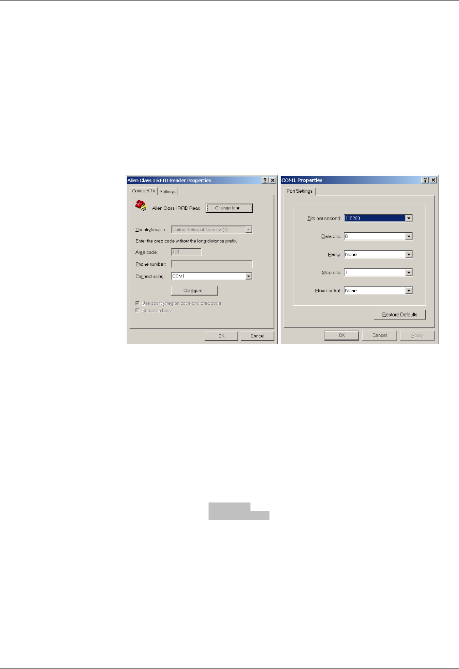
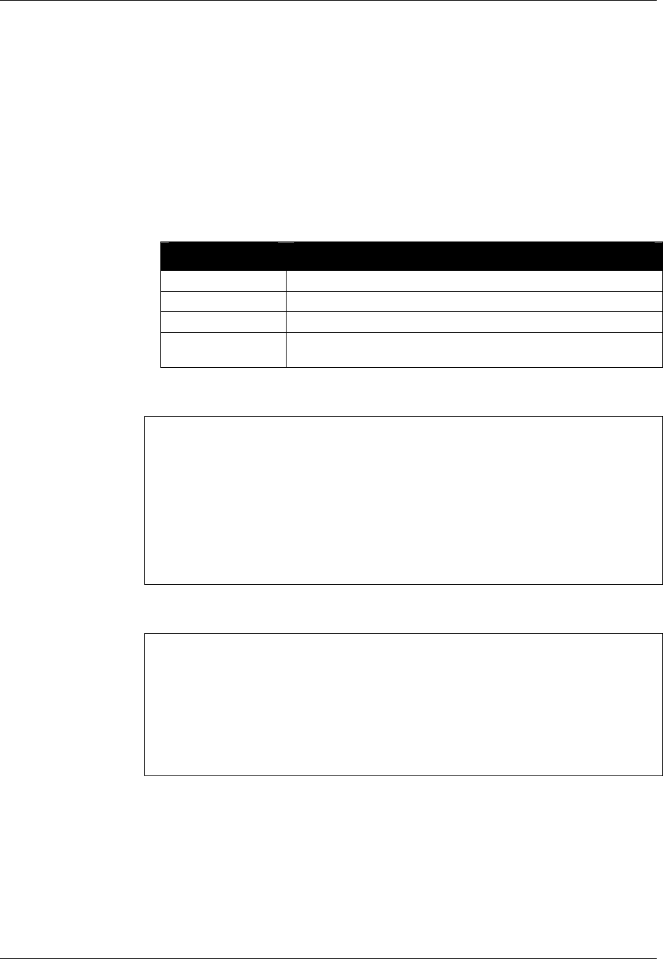
4. Enter (or verify) the following settings to configure the serial communications
program:
Baud Rate : 115200
Data Bits : 8
Parity : None
Stop Bits : 1
Flow Control : None
Once configured, the software should allow you to communicate with the
RFID Reader. HyperTerminal example configuration screens are shown
below:
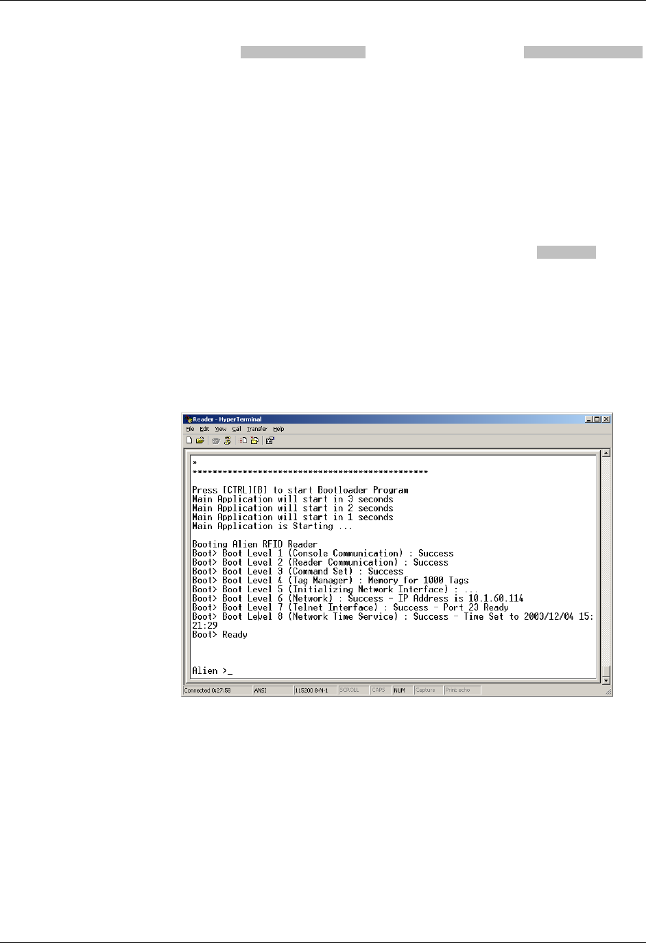
5. Power up the reader, and observe the information reported over the serial
port. Perhaps the most important bits of information are the network settings,
since you need to know this in order to communicate with the reader using
TCP/IP.
The ALR-9800 displays a block of text similar to the following, toward the end
of the bootup sequence:
=============================================
---------------------------------------------
Network Settings:
MAC Address : 00:80:66:10:2D:12
DHCP : 1
IP Address : 10.9.8.10
Netmask : 255.255.255.0
Gateway : 10.9.8.2
DNS : 10.9.8.1
TimeServer : time-a.timefreq.bldrdoc.gov
TimeZone : -7
---------------------------------------------
=============================================
Similarly, the ALR-9770 displays a block of text similar to the following when
it boots up:
CHAPTER 1 INTRODUCTION
READER INTERFACE GUIDE
DOC. CONTROL # 8101938-000 REV 05
5
ixp1 Link encap:Ethernet HWaddr 00:0A:55:00:01:10
inet addr:10.9.8.10 Bcast:10.255.255.255 Mask:255.255.255.0
UP BROADCAST RUNNING MULTICAST MTU:1500 Metric:1
RX packets:602 errors:0 dropped:0 overruns:0 frame:0
TX packets:5 errors:0 dropped:0 overruns:0 carrier:0
collisions:0 txqueuelen:256
For all other readers, the bootup trace displays text such as the following:
Boot> Booting Alien RFID Reader
Boot> Boot Level 1 (Console Communication) : Success
Boot> Boot Level 2 (Reader Communication) : Success
Boot> Boot Level 3 (Command Set) : Success
Boot> Boot Level 4 (Tag Manager) : Memory for 1000 Tags
Boot> Boot Level 5 (Initializing Network Interface) : ...
Boot> Boot Level 6 (Network) : Success - IP Address is 10.9.8.10
Boot> Boot Level 7 (Telnet Interface) : Success - Port 23 Ready
Both traces indicate that the reader can be contacted over TCP/IP at the
address 10.9.8.10, on port 23.
6. If your reader supports the Alien Reader Protocol over serial the serial
interface, you will see the "Alien >" command prompt. At the command
prompt, you may now type any command followed by the [ENTER] key to
submit the command.
The following basic commands are helpful in verifying the reader-host
interface:
• "Help" (or “h”) – provides a list of all commands available
• "Info" (or “i”) – provides a list of current settings for the reader
• "get TagList" (or "t") – scans field immediately for tags and reports the
results
NOTE: RFID Reader commands are case insensitive and may be typed in all
lowercase characters, if preferred.

INTRODUCTION CHAPTER 1
READER INTERFACE GUIDE
DOC. CONTROL # 8101938-000 REV 05
6
For a detailed explanation of all commands available, please refer to the
chapter titled Alien Reader Protocol.
Network Communication
TCP/IP communication requires a network connection via the reader’s Ethernet
port and allows the reader to operate like a Telnet server.
This mode offers the same form of command line interaction with the RFID
Reader as the serial interface, but requires the RFID Reader to be configured for
and running on a network in order to use it.
By default, all RFID Readers are pre-configured to use DHCP when presented
with an Ethernet connection. However, you must first establish a direct serial
connection in order to learn the reader’s IP Address, or be able to detect
"heartbeat" messages sent out over the network by the reader.
Determine the Reader's Network Settings
Once your readers are set up and configured, you should either keep a record of
their addresses, or use some other mechanism for finding them, such as the
reader's Heartbeat messages (described later). Following are instructions for
querying the reader for this information.
ALR-9800 AND ALR-9770
All of the relevant network settings for the ALR-9800 and ALR-9770 readers are
displayed in the bootup sequence (see previous topic on Serial Communication),
notably, the IP Address and Subnet Mask.
ALL OTHER READERS
There are five network commands that are used for querying the reader for its
network configuration.
get DHCP
get IPAddress
get Netmask
get Gateway
get DNS
Once you have the IPAddress and Netmask of the reader, you can connect to it
using TCP/IP.
Connecting via TCP/IP
The reader's TCP/IP interface mimics a basic telnet interface, so you can use
any telnet client to connect to the reader. Windows users can use the telnet
command at the command prompt or "Start -> Run" window:
telnet <ipaddress> <command port>
For instance, in the earlier example, the command would be:
telnet 10.9.8.10 23

CHAPTER 1 INTRODUCTION
READER INTERFACE GUIDE
DOC. CONTROL # 8101938-000 REV 05
7
To do this programmatically, simply open a TCP socket to the reader on its
command port (default is 23) and begin reading. Refer to chapter 4, Alien Reader
Protocol, for details on how to properly terminate command strings, detect the
end of a reader's response, and disable the "Alien >" prompt text from the
returned data. Default settings are:
Username = alien
Password = password
You are now ready to interact with the reader. For telnet operation, you use the
same text-based commands as in direct serial communication. The only
difference is in the use of the “q” command to quit the telnet session and
disconnect the session. The reader automatically disconnects an idle TCP/IP
connection, if there has been no activity longer than the NetworkTimeout setting.
Reader commands and instructions on their use are provided later in the chapter
titled, Alien Reader Protocol.
TCP/IP Configuration
To configure the system for network operation, you will use the commands
shown under the "NETWORK" heading of the reader's "Help" display.
There are five network commands that are used for network configuration:
get|set DHCP
get|set IPAddress
get|set Netmask
get|set Gateway
get|set DNS
1. To view the command list, type “h” or “help”.
If DHCP is supported at your site:
2. Type “set DHCP=ON”. DHCP automatically configures the rest of the
network parameters the next time the reader boots.
3. Skip to step 7.
If DHCP is not supported at your site:
4. Type “set DHCP=OFF”. The reader returns the message “DHCP = OFF”.
5. Contact your system administrator for the following parameter values:
IPAddress
Netmask (also known as Subnet Mask)
Gateway (optional)
DNS (optional)
6. Type each of the 4 commands below with the assigned values:

INTRODUCTION CHAPTER 1
READER INTERFACE GUIDE
DOC. CONTROL # 8101938-000 REV 05
8
set IPaddress = xxx.xxx.xxx.xxx
set Netmask = xxx.xxx.xxx.xxx
set Gateway = xxx.xxx.xxx.xxx (optional)
set DNS = xxx.xxx.xxx.xxx (optional)
As each value is accepted, the reader replies with the accepted value.
7. Type “Reboot” to reboot the reader and apply the new network settings.
The network settings can be immediately applied in the ALR-9800 by using
the "NetworkReset" command. This causes the network interfaces to be shut
down and restarted with the new settings. Note that both the "Reboot" and
"NetworkReset" commands will drop any active TCP/IP connections.

CHAPTER 2 READER FUNDAMENTALS
READER INTERFACE GUIDE
DOC. CONTROL # 8101938-000 REV 05
9
CHAPTER 2
Reader Fundamentals
This chapter provides an overview of the major features found in an Alien RFID
Reader. Specific instructions for setting up a reader are provided in the previous
chapter. Reader commands and their uses are covered in the next chapter.
Introduction
The most basic function of the RFID Reader is to read RFID tags and to give a
user or application access to a list of these tags. The RFID Reader is designed to
perform this function either connected to a host via serial cable, or on a network.
To assist in the administration of networked operation, the reader has two
important features designed to simplify network management:
Reader "heartbeats" allow network applications to easily discover
readers on a network.
Autonomous Mode allows unattended readers to look for tags and send
notification messages to listening services on the network when certain
conditions arise.
These important concepts, along with the basics of communicating with the
reader, are discussed in this chapter.
Reader Discovery and the Reader Heartbeat
One of the problems common to many network appliances is simply discovering
the address of the device on the network. To operate these devices over the
network, users must know the device’s IP address.
If an IP address is hard-coded into the device, this problem is solved, and often a
label on the device can be used to indicate the IP address.
However, many systems do not use hard-coded IP addresses, requiring the
network to assign an address each time the device is booted. This is called
DHCP, which stands for Dynamic Host Configuration Protocol.
DHCP and Automatic Discovery
The DHCP mode of configuration eliminates the need for the user to perform
network configuration for the device. The device simply is plugged into the
network socket, booted, and immediately becomes a citizen of the network,
acquiring its network settings directly from the DHCP server..
However, the user still needs to learn the IP address of the device. All that is
known at this point is that the device does have an IP address and has booted
itself on the network. The actual IP address the device is using is still not known.

READER FUNDAMENTALS CHAPTER 2
READER INTERFACE GUIDE
DOC. CONTROL # 8101938-000 REV 05
10
Serial Interrogation
One of the simplest methods to find out the reader’s IP address is to connect via
the RS-232 port and type the command get IPaddress. The reader
responds with the IP address currently in use.
However, this requires a physical connection between a host computer and the
reader—a connection that in many cases is simply not practical to set up.
Additionally, as noted previously, the ALR-9800 and ALR-9770 readers do not
provide a serial command interface at this time.
Network Heartbeats
Another way to find out a reader’s IP address is to listen for its heartbeat
messages over the network.
After a reader has booted successfully onto a network it periodically broadcasts a
heartbeat message over the network. This heartbeat can be intercepted by
network applications, and provides enough information about the reader to locate
it on the network and begin communication with it.
In network parlance, the heartbeat message is sent via UDP (Universal
Datagram Protocol) packets to all network addresses on the reader’s subnet.
There are three relevant configuration options available via the reader’s
command line to affect this heartbeat:
set | get HeartbeatTime: This command specifies the time interval
separating successive heartbeat messages sent out over the network.
The time is specified in seconds, with a value of zero turning off the
heartbeats. The default value is 30 seconds, i.e. send out a heartbeat
message every 30 seconds.
set | get HeartbeatPort. This command specifies the port number that
the UDP heartbeat messages are addressed to. This is the port number
that must be listened to by interested parties on the network. The default
value for this setting is 3988, i.e. send out a heartbeat message to UDP
port 3988 of every machine on the subnet.
set | get HeartbeatAddress. This command specifies a particular IP
Address that the UDP heartbeat messages are addressed to. The default
value is 255.255.255.255, which is a special "multicast" addressed which
allows any machine on the subnet to receive the heartbeats. Any other
HeartbeatAddress results in the heartbeats going only to the machine at
that address.
set | get HeartbeatCount. This command is implemented only on the
ALR-9800, and allows you to specify the total number of heartbeat
messages to send. This allows for the immediate discovery of readers as
they come online, but doesn't continuously load the network with
unnecessary traffic.
The format of the heartbeat is a small XML text-based message, containing
information about the reader (name and type), the reader’s network connection
(IP address and command port) and the length of time until the next heartbeat
will be sent out.

CHAPTER 2 READER FUNDAMENTALS
READER INTERFACE GUIDE
DOC. CONTROL # 8101938-000 REV 05
11
<Alien-RFID-Reader-Heartbeat>
<ReaderName>Alien RFID Reader</ReaderName>
<ReaderType>
Alien RFID Tag Reader, Model: ALR-9780
(Four Antenna / EPC Class 1 / 915 Mhz)
</ReaderType>
<IPAddress>10.1.60.5</IPAddress>
<CommandPort>23</CommandPort>
<HeartbeatTime>30</HeartbeatTime>
<MACAddress>01:02:03:04:05:06</MACAddress>
</Alien-RFID-Reader-Heartbeat>
HEARTBEAT XML TAGS
ReaderName is the user-defined name associated with the reader. This name
can be set by a user to help identify which reader is which.
For example, multiple readers in a warehouse may be named “loading bay 1”,
“loading bay 2” etc., thus providing a clear indication as to the physical location of
the reader.
ReaderType details the specific type of reader sending out the heartbeat. This
information is hard-coded into the reader’s firmware and is not user-configurable.
IPAddress and CommandPort elements detail the location of the reader on the
network. The IP address is simply the network address of the reader. The
command port is the port number on which the reader is listening for incoming
user commands. Typically, this is port 23, the standard telnet port, allowing a
user to communicate with the reader over the network by typing “telnet
[IPAddress]” into the command line of most computers.
HeartbeatTime is the time until the next heartbeat. This time (in seconds)
enables any application software to detect when a reader is powered-down or the
network connection breaks; if a new heartbeat is not received after the expected
time elapses, then such an interruption to normal service can be detected.
MACAddress gives the unique identifier assigned to the reader's network
interface hardware by the manufacturer. It is provided in the ALR-9800 and ALR-
9774 heartbeat messages only.
HEARTBEATS AND SOFTWARE
The RFID Developer’s Kit CD that may accompany the reader provides source
code and software libraries to listen for these network heartbeats, in the Java,
.NET, and Visual Basic languages.
The Alien RFID Gateway application, bundled with all readers, uses the Java
version of these libraries to build its active reader list on the main screen. The
latest Gateway version at the time of this writing is v2.14.13. Alien recommends
users download the install the latest version of Gateway software.
TagList Concepts
During normal operation, the reader always has a concept of "what's out there"
by maintaining an internal list of the tags that are active. Active tags are those
read by the reader at least once within a predefined interval. Any new tags
presented to the reader are added to the list, and any tags that have not been
seen for a period of time (the PersistTime) are removed from the list.
READER FUNDAMENTALS CHAPTER 2
READER INTERFACE GUIDE
DOC. CONTROL # 8101938-000 REV 05
12
At any time, a programmatic call can be made to the reader to retrieve this list of
tags.
PersistTime
The “persist time” defines the duration between the time a tag was last read and
the time it is automatically purged from the TagList. Setting this value to a small
time (~1 second) will cause the TagList to contain only what the reader has seen
in the last second, i.e., a fair representation of what the reader sees at any one
time. Setting the persist time to a long duration allows a history of tags to be built
up. For example, setting the persist time to 3600 seconds allows a list to be built
up detailing all the tags that were read over the last hour.
Setting PersistTime to –1 has the special effect of keeping tags on the list
indefinitely until the TagList is delivered to a host, at which point the TagList is
cleared. This is the default value, and the only value allowed on the ALR-9770.
Tag Details
Each entry in the TagList contains a number of sub fields: the Tag's unique ID,
the read count (the number of times the tag has been read in the current
session), the discovery time (the time the tag was first seen), the last observed
time, the antenna (the antenna ID that the tag was last read from), and others.
TagList Size
The ALR-9800's TagList can hold up to 6000 tag entries. Other Alien RFID
readers can handle up to 1000 entries.
Reading Tags over the Network
The Alien RFID reader provides two methods with which to read tags: Interactive
Mode and Autonomous Mode.
Interactive Mode - the controlling application issues commands to the
reader to read tags. This command will always immediately return with a
list of tags in the reader's field of view.
Autonomous Mode - the reader constantly reads tags, and may initiate
a conversation with a network listener when certain events arise.
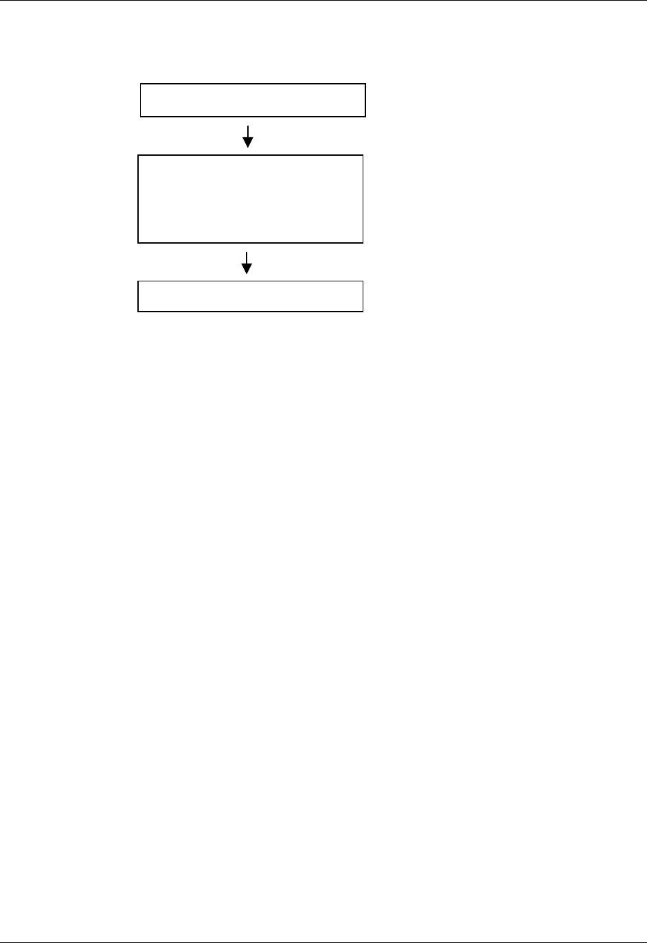
8000 0100 8820 FFA4
8000 0100 8820 3F02
8000 0400 0232 3F06
8020 0150 2057 3F12
8000 0200 8020 3F16
8000 0100 8820 3F09
New tags detected are added to the
Ta
g
List.
Reader TagList...
A
ll tags listed are active.
Tags not read for a while are
removed from the list.

CHAPTER 2 READER FUNDAMENTALS
READER INTERFACE GUIDE
DOC. CONTROL # 8101938-000 REV 05
13
While both methods are equally useful, the choice will ultimately be determined
by the needs of the controlling application.
Although it may be easier and require less coding to work in Interactive Mode, a
little investment in programming effort lets the user set up Autonomous Mode to
provide a more scalable system for multiple readers. In addition, readers that
spend less time communicating with the host can spend more time looking for
tags.
Interactive Mode
Reading tags in Interactive Mode is as simple as issuing a single command to
the reader. This command is get TagList. This causes the reader to initiate
a tag search, and report back the current TagList. Depending on the PersistTime
and recent tag activity, the returned data may include tag read data from
previous reads. Following is an example of what the default TagList format
("Text") looks like.
Tag:041C 1820 2812 4080, Disc:2003/01/21 02:24:00, Last:2003/01/21 02:24:00, Count:1, Ant:0
Tag:1155 8B14 5661 D40B, Disc:2003/01/21 04:14:47, Last:2003/01/21 04:24:00, Count:1, Ant:0
The format of the TagList can be specified using the set TagListFormat
command. One of the options is XML format, which would return the same
TagList as:
<Alien-RFID-Tag-List>
<Alien-RFID-Tag>
<TagID>041C 1820 2812 4080</TagID>
<DiscoveryTime>2003/01/21 02:24:00</DiscoveryTime>
<LastSeenTime>2003/01/21 02:24:00</LastSeenTime>
<ReadCount>1</ReadCount>
<Antenna>0</Antenna>
</Alien-RFID-Tag>
<Alien-RFID-Tag>
<TagID>1155 8B14 5661 D40B </TagID>
<DiscoveryTime>2003/01/21 02:24:00</DiscoveryTime>
<LastSeenTime>2003/01/21 02:24:00</LastSeenTime>
<ReadCount>1</ReadCount>
<Antenna>0</Antenna>
</Alien-RFID-Tag>
</Alien-RFID-Tag-List>
Additional formats include "Terse", and "Custom". See the TagListFormat section
in Chapter 4, Alien Reader Protocol for details on all of the TagList formats.
Autonomous Mode
Autonomous Mode is a configuration and operation mode that enables
automated monitoring and handling of tag data. You first issue a series of
configuration commands to the reader which specify how and when to read tags,
and optionally what to do with the tag data.
Once configured in this mode, the reader can be left to operate on its own. An
application on a host computer can then be set up to listen for notification
messages from the reader containing any tag data that it has read.
READER FUNDAMENTALS CHAPTER 2
READER INTERFACE GUIDE
DOC. CONTROL # 8101938-000 REV 05
14
One of the major benefits to this mode of operation is that many readers can be
configured to send tag messages to a single host. Thus, a single application can
listen for and process data from multiple readers over the network.
A NOTE ABOUT AUTOMODE ON THE ALR-9770
The ALR-9770 reader implements a simplified version of the AutoMode found on
other Alien readers. Digital I/O hasn't been implemented, so the use of start and
stop triggers (discussed on the following pages) doesn't apply. Also, the ALR-
9770 lacks the Notify engine, so there is no asynchronous notification
mechanism.
Defining the Autonomous Read Operation
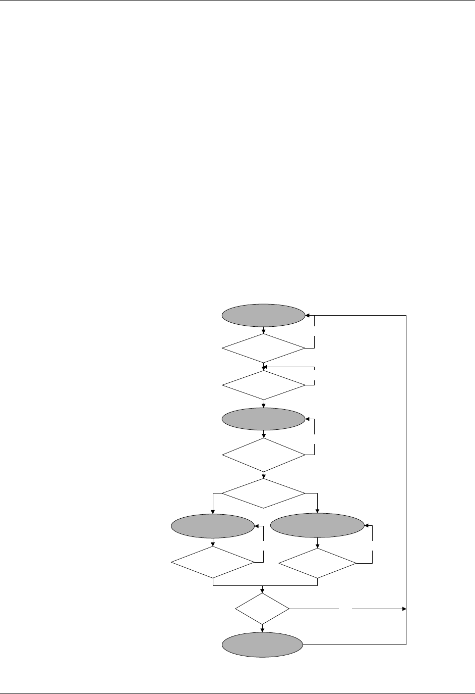
Autonomous Mode functionality is summarized in the state diagram shown
below. Fundamentally, a reader operating in Autonomous Mode moves between
several states: Waiting, Working, Evaluation, and Notification. Waiting, Working,
and Evaluation states have associated with them an optional digital output state
that is set upon entering the state. Movement from one state to the next is
initiated by an expiration of a timer, a triggered event on the digital input lines, or
changes to the TagList.
Each element of the State Diagram is described below. Associated with each
element are one or more commands that are used to configure the reader.
Autonomous Mode State Diagram
Wait
(AutoWaitOutput)
AutoStartTrigger?
AutoAction
(AutoWorkOutput)
AutoStopTimer Expired
or AutoStopTrigger?
Evaluation
(New Tag? Programmed?)
True Evaluation
(AutoTrueOutput)
False Evaluation
(AutoFalseOutput)
AutoTruePause
Expired?
AutoFalsePause
Expired?
Notification
Needed?
Issue
Notification
no
no
no
no
AutoStartPause Expired?
(ALR-9800)
no
no

CHAPTER 2 READER FUNDAMENTALS
READER INTERFACE GUIDE
DOC. CONTROL # 8101938-000 REV 05
15
ENTER AUTONOMOUS MODE (Not shown on the state diagram.)
The user puts the reader into Autonomous Mode with the set AutoMode
command. set AutoMode=On puts the Reader into Autonomous Mode. Set
AutoMode=Off turns off Autonomous Mode.
WAITING STATE
Upon entering Autonomous Mode, the reader automatically enters the Waiting
State. While waiting for a Start Working Trigger (see below) the reader holds the
digital output lines at a value set by the AutoWaitOutput command. For
example, set AutoWaitOutput=1 causes digital output line 1 to go high
while the reader is in the Waiting state.
START WORKING TRIGGER
The receipt of a trigger pattern on the digital input lines causes the reader to
move from the Waiting state to the Working state. The start condition is set by
the AutoStartTrigger command. The AutoStartTrigger command
takes two parameters, a rising edge pattern and a falling edge pattern. Each
pattern is a single integer which is a bitmap of the desired input triggers, where
input pin #1 is represented by bit 0, input pin #2 is represented by bit 1, etc.
The table below illustrates the bitmap values that correspond to different pin
combinations. This table holds for both input as well as output pin bitmaps.
Digital
Input
Value
0 1 2 3 4 5 6 7 8 9 10 11 12 13 14 15
Pin #1 - ✔ - ✔ - ✔ - ✔ - ✔ - ✔ - ✔ - ✔
Pin #2 - - ✔ ✔ - - ✔ ✔ - - ✔ ✔ - - ✔ ✔
Pin #3 - - - - ✔ ✔ ✔ ✔ - - - - ✔ ✔ ✔ ✔
Pin #4 - - - - - - - - ✔ ✔ ✔ ✔ ✔ ✔ ✔ ✔
The command, set AutoStartTrigger=2,0 causes the reader to enter
the working state on receipt of a rising edge on pin 2, while set
AutoStartTrigger=0,3 causes the reader to enter the working state after
the receipt of a falling edge on pins one or two. set
AutoStartTrigger=0,0 causes the reader to immediately drop into the
Working state.
The ALR-9800 has an additional property, AutoStartPause, which causes the
reader to pause the specified number of milliseconds after receiving a start
trigger before transitioning to the working state.
WORKING STATE
In the working state, the reader holds the digital output lines at the value defined
by the AutoWorkOutput command. set AutoWorkOutput=3 holds the
first two output lines high while the reader is working. The action the reader
performs while in the working state is determined by the AutoAction
command. set AutoAction=Acquire causes the reader to repeatedly
acquire TagList data using the parameters set in the AcquireMode and

READER FUNDAMENTALS CHAPTER 2
READER INTERFACE GUIDE
DOC. CONTROL # 8101938-000 REV 05
16
PersistTime commands. The reader continues working until the Stop
Working Trigger conditions are met. (see below)
STOP WORKING TRIGGER/TIMER
Like the Start Working Trigger, the Stop Working Trigger can be a change on the
digital input lines, but can also be the expiration of a timer. Use the
AutoStopTrigger command with a rising, falling edge pattern to set the
trigger conditions. set AutoStopTrigger=1,0 looks for a rising edge on
pin 1 before leaving the Working state. In addition, one may use the
AutoStopTimer command to repeat the Working action for a specified period
of time. For example, set AutoStopTimer=1300 causes the reader to
perform the Working action for 1.3 seconds before moving on to the Evaluation
stage. If both a stop trigger and a stop timer are specified, whichever event
happens first fill stop the working state.
EVALUATION
At the Evaluation decision point, the reader looks to see if new tags have been
added to the TagList since the last evaluation. If so, it drops to the
AutoTruePause state, if not, it drops to the AutoFalsePause state. Note: the
Evaluation looks at the TagList and therefore is very much dependent on the
value of the PersistTime setting.
TRUE/FALSE PAUSE
After evaluation, the Reader sets the output lines to the values specified in the
AutoTrueOutput and AutoFalseOutput commands. This condition is
held for AutoTruePause or AutoFalsePause milliseconds before the test
for Notification begins. For example, set AutoTrueOutput=1 and set
AutoTruePause=20 cause the reader to hold output pin #1 high (and all
others low) for 20 milliseconds before proceeding.
NOTIFICATION
If NotifyMode is enabled (set NotifyMode=On) and the specified
NotifyTrigger has occurred, the reader issues an notification message. The
NotifyTrigger is specified with the set NotifyTrigger command and can
be set to “Add”, "Remove”, “Change”, “True”, “False”, or "TrueFalse", as
described in the next topic.
If a notification is to be issued, the TagList data is sent to the NotifyAddress.
The reader then returns to the Waiting state.
Autonomous Mode Examples
EXAMPLE 1 - BACKGROUND READING
In this case, we would like the reader to monitor the tag field continuously. The
application will periodically ask for the TagList. If a new tag is seen, output pin 1
will be flashed high for 500 msec. Otherwise, output pin 2 will be flashed high for
500 msec.

CHAPTER 2 READER FUNDAMENTALS
READER INTERFACE GUIDE
DOC. CONTROL # 8101938-000 REV 05
17
AutoModeReset
set AutoAction = Acquire
set AutoStartTrigger = 0,0
set AutoStopTimer = 0
set AutoTrueOutput = 1
set AutoTruePause = 500
set AutoFalseOutput = 2
set AutoFalsePause = 500
set AutoMode = On
EXAMPLE 2 - TRIGGERED READING
Here a forklift will cause an electric eye to send a signal to the reader. We want
the reader to look for a rising edge on this signal and scan for tags for 1.8
seconds before going back to the Waiting state. We won't make any changes to
the output pins.
AutoModeReset
set AutoAction = Acquire
set AutoStartTrigger = 1, 0
set AutoStopTimer = 1800
set AutoTruePause = 0
set AutoFalsePause = 0
set AutoMode = On
EXAMPLE 3 - TRIGGERED READING WITH NOTIFICATION
A trigger is used to start the reading. If a tag is found, send an email message.
After the email is sent, return to the waiting state.
AutoModeReset
set AutoAction = Acquire
set AutoStartTrigger = 1, 0
set AutoStopTimer = 0
set AutoTruePause = 0
set AutoFalsePause = 0
set NotifyAddress = borg@mycompany.com
set MailServer = mail.mycompany.com
set NotifyTrigger = Add
set NotifyMode = On
set AutoMode = On
Notification Mode
The last stage in configuring the Autonomous Mode is to tell the reader under
what conditions to notify listeners about TagLists. Listeners (network applications
/ people) are notified only when specific conditions arise, such as when new tags
are read, or when tags disappear from view.
Note: Notification Mode is not supported on the ALR-9770 reader at this time.
NotifyTime
The NotifyTime command instructs the reader to send out a copy of its
TagList to a listener every n seconds, regardless of whether the TagList has
changed or not. This is a simple way to force the reader to send out its
TagList to a listener.

READER FUNDAMENTALS CHAPTER 2
READER INTERFACE GUIDE
DOC. CONTROL # 8101938-000 REV 05
18
NotifyTrigger
The NotifyTrigger command specifies a condition that must occur before a
TagList is sent out to a listener. There are a number of possible triggers that
can be used:
Trigger Trigger Condition Tag Data Included
Add A new tag was read and added to the TagList. Only the added tags.
Remove A tag was removed from the TagList. Only the removed tags.
Change A tag was either added to, or removed from,
the TagList. Entire TagList.
True
The evaluation task of the autonomous state
loop evaluates to true
(typically when a tag is added to the TagList).
Entire TagList.
False
the evaluation task of the autonomous state
loop evaluates to false
(typically when no tag is added to the TagList)
Entire TagList.
TrueFalse
the evaluation task of the autonomous state
loop evaluates to true or false
(i.e. every autonomous mode cycle)
Entire TagList.
NotifyAddress
You must tell the reader where to send notification messages when it is operating
in Autonomous Mode.
The reader can be instructed to send messages to a specific machine on the
network, or via email to a specific email address. This is configured using the
command:
set NotifyAddress = <address>
The format of <address> indicates the method of delivery:
NotifyAddress Description
hostname:port Send a message to a specified port on a networked machine.
The address takes the form “hostname:port.” For example,
“123.01.02.98:3450” or "listener.alientechnology.com:10002”
user@domain.com
Send a message via e-mail to the address specified. The
address is specified in standard email form, i.e.,
user@domain.com
NOTE: the MailServer parameter must be configured for this
to work.
serial Send a message to the serial connection. The word “serial” is
used as the address, and is not case sensitive.
NotifyFormat
You can tell the reader the format for any notification that it issues. When a
notification message is sent out, it contains two parts:
CHAPTER 2 READER FUNDAMENTALS
READER INTERFACE GUIDE
DOC. CONTROL # 8101938-000 REV 05
19
The first part, the header, provides details about the reader that sent the
message, and the reason the message was sent.
The second part is the TagList - either newly added or removed tags, or
the complete list of tags as seen by the reader, depending on the
NotifyTrigger.
The format of the message is configured using a single command:
set NotifyFormat = format
The format may be one of the following:
NotifyFormat Description
Text Plain text messages, one tag ID per line.
Terse Plain text messages, one tag ID per line, compact form
XML XML text format
Custom Same as Text format, except the contents of each tag ID line is
defined by the TagListCustomFormat parameter
Text-formatted notifications take the form:
#Alien RFID Reader Auto Notification Message
#ReaderName: Spinner Reader
#ReaderType: Alien RFID Tag Reader, Model: ALR-9780
(Four Antenna / Class 1 / 915Mhz)
#IPAddress: 10.1.70.13
#CommandPort: 23
#Time: 2003/01/21 12:48:59
#Reason: TEST MESSAGE
Tag:1115 F268 81C3 C012, Disc:2003/01/21 09:00:51, Last:2003/01/21
09:00:51, Count:1, Ant:0
Tag:0100 0100 0002 0709, Disc:2003/01/21 11:00:10, Last:2003/01/21
11:00:10, Count:1, Ant:0
#End of Notification Message
Terse-formatted notifications take the form:
#Alien RFID Reader Auto Notification Message
#ReaderName: Spinner Reader
#ReaderType: Alien RFID Tag Reader, Model: ALR-9780
(Four Antenna / Class 1 / 915Mhz)
#IPAddress: 10.1.70.13
#CommandPort: 23
#Time: 2003/01/21 12:48:59
#Reason: TEST MESSAGE
1115 F268 81C3 C012,1,0
0100 0100 0002 0709,1,0
#End of Notification Message

READER FUNDAMENTALS CHAPTER 2
READER INTERFACE GUIDE
DOC. CONTROL # 8101938-000 REV 05
20
XML-formatted notifications take the form:
<Alien-RFID-Reader-Auto-Notification>
<ReaderName>Spinner Reader</ReaderName>
<ReaderType>
Alien RFID Tag Reader, Model: ALR-9780
(Four Antenna / Class 1 / 915 MHz)
</ReaderType>
<IPAddress>10.1.70.13</IPAddress>
<CommandPort>23</CommandPort>
<Time>2003/01/21 12:49:22</Time>
<Reason>TEST MESSAGE</Reason>
<Alien-RFID-Tag-List>
<Alien-RFID-Tag>
<TagID>0102 0304 0506 0709</TagID>
<DiscoveryTime>2003/01/17 11:37:01</DiscoveryTime>
<LastSeenTime>2003/01/17 11:37:01</LastSeenTime>
<Antenna>0</Antenna>
<ReadCount>1413726</ReadCount>
</Alien-RFID-Tag>
<Alien-RFID-Tag>
<TagID>2283 1668 ADC3 E804</TagID>
<DiscoveryTime>2003/01/19 07:01:19</DiscoveryTime>
<LastSeenTime>2003/01/19 07:01:19</LastSeenTime>
<Antenna>0</Antenna>
<ReadCount>1</ReadCount>
</Alien-RFID-Tag>
</Alien-RFID-Tag-List>
</Alien-RFID-Reader-Auto-Notification>
An example of a custom-formatted notification might be:
#Alien RFID Reader Auto Notification Message
#ReaderName: Spinner Reader
#ReaderType: Alien RFID Tag Reader, Model: ALR-9780
(Four Antenna / Class 1 / 915Mhz)
#IPAddress: 10.1.70.13
#CommandPort: 23
#Time: 2003/01/21 12:48:59
#Reason: TEST MESSAGE
Tag 1115 F268 81C3 C012 was read 3 times
Tag 0100 0100 0002 0709 was read 1 times
#End of Notification Message
Listening for Tags over the Network
When a reader has been configured for Autonomous Mode, interactive
communication with the reader is unnecessary and it can be left to work on its
own. It is then up to the application to listen for any notification messages from
the reader.
Libraries included in the RFID Reader Developer’s Kit provide this functionality in
Java, .NET, and Visual Basic environments. In both cases, setting up a listening
service is a simple coding task, involving less than ten lines of code.

CHAPTER 3 TAG FUNDAMENTALS
READER INTERFACE GUIDE
DOC. CONTROL # 8101938-000 REV 05
21
CHAPTER 3
Tag Fundamentals
Introduction
RFID tag reading is not just about getting the tag ID from a tag into the reader.
There are different methods available to perform this basic operation, and
different parameters and settings that can be altered to tweak the performance of
this basic operation.
Alien RFID Tags
For the purposes of this Reader
Interface Guide, it is assumed you will
be using either the Alien beam-
powered tag (Class I) or the Alien long-
range battery-powered tag, both of
which use modulated backscatter
communications.
Alien NanoBlock Tags
Alien’s offerings in the Class I tag
category use proprietary NanoBlock™
ICs to meet the cost and size
requirements of the EPCglobal
specification.
This is a completely “passive” tag by both common definitions of the term in both
its means of communication (backscatter) and its power source (beam-powered).
Thus, if you hear Aliens refer to a “passive tag,” this is the type of tag they are
talking about.
Battery Assisted Passive (BAP) Tags
Alien’s long-range, battery-assisted passive tag would be categorized as a Class
3 “dynamic tag” under the EPCglobal scheme, though with performance
enhancements over those of the basic Class 3 tag.
These battery tags can be configured for any number of specific applications.
Alien’s Temperature Tag, in particular, allows manufactures and shippers of
temperature-sensitive and perishable products to track temperature variations
these products encounter during handling. Such temperature records can help
pinpoint handling problems and calculate more realistic shelf-life and expiration
dates.
Battery tags may be used effectively for supply chain applications as well as
commercial applications including fleet management, automatic toll collection,
and equipment tracking.
Examples of Alien RFID Tag and
A
ntenna Designs.

TAG FUNDAMENTALS CHAPTER 3
READER INTERFACE GUIDE
DOC. CONTROL # 8101938-000 REV 05
22
Acquisition Modes
The AcquireMode property defines the method used to read tags in the field.
There are two distinct methods for reading tags, and the choice of one method
over another depends on the application at hand.
You specify the Acquire Mode by issuing the set AcquireMode command. It
can take one of two values, "Global Scroll" or "Inventory”.
Global Scroll
Global Scroll is the most primitive of tag ID reading operations supported by the
Alien RFID Reader system. When a global scroll command is issued, the RFID
Reader sends a single command over the air to all and any tags. That command
is simply a request for any tag to immediately send back its ID to the RFID
Reader.
The simplicity of this command is both its advantage and its downfall: The
command is very quick to execute as it involves only one round trip between the
reader and the tag. However, because the command is so simple, problems may
arise if there is more than one tag in the field. At this point, multiple tags will all
receive the same command, and will all send back their IDs to the reader at
virtually the same time. A situation such as this makes it difficult for the reader to
discern individual IDs among the general noise. Typically one or two of the
loudest or closest tags will be decoded, but the majority will not be discerned.
This is analogous to walking into a dark room full of people and shouting out the
command “if anyone can hear me, shout your name back now”. If there is one
person in the room with you, you will be able to hear their name. If there are
multiple people in the room, the results will be noise. Maybe you will be able to
make out one or two names, but typically not more than that.
There are many applications where global scroll is the best tag reading method
to use. These applications typically expect just one or two tags in the field of view
at any one time, such as conveyor belt or tollbooth applications. For these
systems, global scroll outperforms a full inventory by a factor of three as far as
individual read rates are concerned.
Inventory
The inventory command is a full-featured system for discerning the IDs of
multiple tags in the field at the same time. This single high-level command
transforms itself into a complex series of reader-tag interrogations that eventually
resolve themselves into a single list of tag IDs seen by the RFID Reader. This
method of interrogation and evaluation of multiple tags is known as an anti-
collision search.
Continuing the analogy used in the global scroll description, the anti-collision sort
works in the following way: You walk into a dark room full of people and instruct
everyone to stand up. Then you start with the letter ‘A’ and tell anyone whose
name begins with this letter to shout their name back. You may get zero replies,
one reply, or multiple noisy replies. If you can clearly make out any individual
name from the noise, you shout back telling that person to sit down and be quite
from now on. Next repeat the series of events, this time telling anyone whose
name begins with ‘AA’ to shout back their name. If you can pick out one name,
tell that person to sit down and be quite. You repeat this until no names are
heard at all, each time adding a letter such as ‘AB’, ‘AC’. When it gets to the point

CHAPTER 3 TAG FUNDAMENTALS
READER INTERFACE GUIDE
DOC. CONTROL # 8101938-000 REV 05
23
that there are no more names to be heard, you move on to the letter ‘B’ and
repeat the series. By the time you’ve been through the letter ‘Z’, you should have
been able to get everyone’s name, and everyone should be sitting down. At this
point the sort has been finished.
Obviously this sort algorithm is far more complex than the global scroll algorithm,
requiring many more reader-tag instructions. However the Alien RFID Reader
considerably optimizes this basic sort method, and in doing so still provides a
very fast and efficient sort algorithm.
Acquire Parameters
When the reader scans for tags, it can automatically perform a complex
sequence of repeated wakes, sleeps, and reads. This sequence is defined by the
acquire parameters, and by adjusting each value you can configure the Reader
to perform optimally, depending on the particular use case.
When the reader does an acquire action, it performs a total number of acquire
cycles specified by the AcqCycles parameter. Each cycle consists of a number
of Wakes (given by AcqEnterWakeCount) on each antenna, then a number
of reads (given by AcqCount) and Sleeps (given by AcqSleepCount) on
each antenna. Finally, after all of the cycles have completed, a number of Wakes
(given by AcqExitWakeCount) are issued on each antenna.
The Wakes and Acquires all act on the current Tag Mask. The Sleeps act only on
tags as they are found.
The acquire parameters are demonstrated by the following pseudo-code:
foreach cycle in AcqCycles
foreach wake in AcqEnterWakeCount
foreach antenna in AntennaSequence
Wake (using current mask)
next antenna
next wake
foreach count in AcqCount
foreach antenna in AntennaSequence
DoAcquisition (using currentMask)
foreach sleep in AcqSleepCount
Sleep(TagsFound)
next sleep
next antenna
next count
next cycle
foreach wake in AcqExitWakeCount
foreach antenna in AntennaSequence
Wake(currentMask)
next antenna
next wake
Masks and Tag Memory Structure
Many commands aimed at Alien RFID tags require the setting of a mask, which
directs the commands only at the tags who's ID matches the mask. This

TAG FUNDAMENTALS CHAPTER 3
READER INTERFACE GUIDE
DOC. CONTROL # 8101938-000 REV 05
24
mechanism allows commands to be sent to one specific tag, a selective group of
tags, or the whole field of tags.
To understand the use of masks, a basic understanding of tag memory structure
is first required.
Class I Tag Memory
Class I tags from Alien contain 96 bits of programmable memory, of which 64 bits
are user-programmable. The remaining 32 bits are controlled by the reader to
record state and checksum information inside the tag.
Checksum EPC Code (or User ID Code) Lock PC
B
yte 0 1 0 1 2 3 4 5 6 7 0 0
B
it 0-7 8-15 0-7 8-15 16-23 24-31 32-39 40-47 48-55 56-63 0-7 0-7
Class I Tag Memory Structure
The 64-bit ID Code (either a fully qualified EPC code or user-defined ID Code) is
address from left to right, where the leftmost bit (the Most Significant Bit) is bit 0,
and the rightmost bit (the Least Significant Bit) is bit 63. There is no restriction on
the data that resides in this portion of the tag.
The checksum is calculated over the 64 bits of the ID Code only. The checksum
is calculated and programmed into the tag automatically by the reader. This
checksum is calculated using the CCITT-16 standard.
The Lock and PassCode (PC) bytes stored at the end of tag memory are used to
lock a tag and kill a locked tag. Each of these codes takes exactly one byte. The
user can control the value of the PassCode, passing it in as a parameter to the
Lock command. The reader takes full control of the Lock byte, allowing it to flag
the tag as either locked or unlocked.
For further details on programming tag IDs and tag memory, please see the Tag
Programming chapter.
Addressing a Subset of Tags
One of the more useful applications of the mask command is to address a subset
of tags in the field. This is achieved using partial masks.
For example, the following mask command can be issued to address only tag IDs
that start with the numbers "8000 0040":
set Mask = 32, 0, 80 00 00 40
The first value is the length of the mask - 32 bits (4 bytes x 8 bits/byte). The
second value is the starting position in the ID - bit 0. Finally, a sequence of hex
bytes is given specifying the mask – 80 00 00 40.
Subsequent commands that use a mask will now only be recognized by tags that
start with this tag ID. This can be useful if, for example, the reader is scanning
food items but is only interested in finding a certain brand of breakfast cereal. By
setting the mask to identify only the breakfast cereal tag IDs, any acquire
command on the food items will only return the items of interest. This
methodology works particularly well when combined with the EPC code strategy,

CHAPTER 3 TAG FUNDAMENTALS
READER INTERFACE GUIDE
DOC. CONTROL # 8101938-000 REV 05
25
where each product type and manufacturer code use well-defined memory codes
that can be masked.
Another example is to search for all Class I tags whose last three bits of a 64-bit
EPC code are set to 1. The mask settings for this would be:
set Mask = 3, 61, E0
In other words, length = 3 bits, starting at bit 61, and matching value E0hex. The
mask value is specified as E0hex (11100000binary) and not 07hex (111binary) because
07hex is interpreted as 00000111binary, and when the bit pattern is applied as a
mask, the bits are applied from left to right (most-significant-bit to least-
significant-bit).
Persistent Sleep and Wake
Tags have the ability to be put to sleep and awakened on command. Once tags
have been put to sleep they will ignore any subsequent commands, even if
addressed directly to them. The only command that these slept tags will respond
to is wake, which will bring them back to life and make them respond to all
commands again.
The Sleep and Wake commands can act together in a powerful way to help
address multiple tags in the field.
By default the inventory and global scroll commands will read tags in the field,
and leave them in a wakened state. This means that the very next time an
acquire action is made, the same tags will answer back to the reader, resulting in
an identical TagList.
However it is possible to sleep tags are they are found. Both the inventory and
global scroll modes support this action. In this scenario, as a tag is discovered by
the reader, it is told to sleep. The very next time an acquire command is issued,
the reader will scan the field of tags, but as they are all asleep, they will not
answer and the TagList returned will be empty.
The effects of the sleep-as-found mode can be reverted at any time by issuing a
Wake command. This will immediately wake up all tags in the field of view,
making them ready for subsequent acquire commands.
This is a useful mode to use when dealing with very large numbers of tags in the
field at once (>100 tags). Using these modes, the acquire command can discern
as many tags as it can in one pass, leaving these tags asleep as it finds them.
Then any subsequent acquire commands will now only be dealing with tags it
missed in previous rounds, or tags that have entered the field since the last
round. Thus a large population of tags can be sorted in smaller, more
manageable rounds.
Sleep, Wake, and Masks
The Sleep and Wake commands always work with the current Mask setting.
Therefore it is possible to Sleep a subset of tags before performing an acquire, or
to Sleep all tags then Wake a subset before acquire. Combining Sleep, Wake,
Masks and Acquire Modes offers up many interesting possibilities for tag reading
that will address virtually all problems in the field.
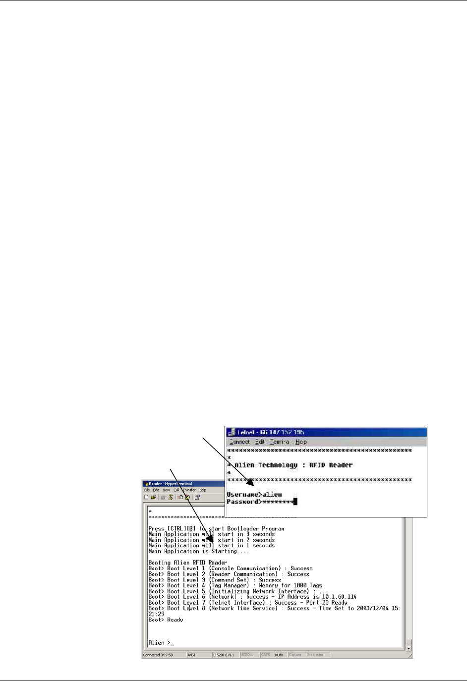
ALIEN READER PROTOCOL CHAPTER 4
READER INTERFACE GUIDE
DOC. CONTROL # 8101938-000 REV 05
26
CHAPTER 4
Alien Reader Protocol
The Alien Reader Protocol is a text-based communications protocol for
configuring and operating an Alien RFID Reader. This chapter describes the
programming interface that links the Alien RFID Reader to the outside world.
For an overview of the reader system and instructions on setting up reader
operation via a host computer, see the chapters entitled: Reader Fundamentals
and Tag Fundamentals.
Reader Operation Overview
As detailed in the previous chapter, you may interact with the reader and
configure its operation using either of two text-based command line methods:
direct serial (RS-232) – if supported by the reader
telnet connection (TCP/IP)
For the purposes of these instructions, the serial and telnet operations are
considered essentially identical. In both cases, the screens look similar and will
thus be considered identical for the purposes of the instructions that follow.
Telnet Exceptions:
In telnet operation you must issue the command “q” to quit the session.
Accessing the reader via telnet requires an authorized user name and
password (both of which can be changed with commands in the General
command set).
Telnet connection
Direct serial connection
via H
yp
erTerminal

CHAPTER 4 ALIEN READER PROTOCOL
READER INTERFACE GUIDE
DOC. CONTROL # 8101938-000 REV 05
27
Overview of Commands
There are two distinct categories of reader activities: those initiated by the host
(Interactive Mode), and those initiated by the reader itself (Autonomous Mode).
INTERACTIVE MODE
Interactive Mode activities are initiated by a program or user who issues
commands to the reader from a separate host computer. The host always
initiates the transaction with a request, and the reader responds with an
immediate reply. The host should wait for a reply before initiating another
command.
Interactive commands are used to configure and operate the reader, as well as to
interrogate tags and retrieve the stored TagList on demand.
AUTONOMOUS MODE
Autonomous Mode activities instruct the reader to perform certain tasks without
outside intervention, according to conditions set by the programmer.
These commands typically tell the reader to read tags based on trigger events
(external digital inputs or internal timers) and then send notification messages to
a host system, depending on various TagList-based triggers. For example, the
reader can be instructed to search the field until it sees a tag, then to read the
new tag and e-mail the event to a specified e-mail address.
Command Format
All commands between the host system and the reader are human readable,
ASCII text-based messages. For example, a command to set the name of the
reader using the "set ReaderName" command takes the form:
Alien >set ReaderName = My Alien Reader[CR][LF]
All commands to the reader are single-line ASCII strings, terminated by a
carriage-return / line-feed pair, written as [CR][LF]. The [CR] character is ASCII
code 0x0D, while the [LF] character is ASCII code 0x0A. These characters are
sometimes written as "\r" and "\n" respectively.
All responses from the reader are either single-line or multi-line ASCII strings,
terminated by [CR][LF][0], where [0] is ASCII code 0x00. When a responses is
comprised of multiple text lines, each line is separated by a single [CR][LF]
sequence.
An example of a command and single-line response is:
Alien >get ReaderName[CR][LF]
ReaderName = Alien Reader[CR][LF][0]
An example of a command and multi-line response is:
Alien >get ReaderVersion[CR][LF]
Ent. SW Rev: 03.00.10 : Jun 08 2004 : 10:54:30[CR][LF]
Country Code: 01, Reader Type: 03, Firmware Rev: 2.1.4[CR][LF][0]
Commands are not case sensitive:
“
set readername” is equivalent to “sET ReADerNaME”.

ALIEN READER PROTOCOL CHAPTER 4
READER INTERFACE GUIDE
DOC. CONTROL # 8101938-000 REV 05
28
Suppressing Command Prompts
By default, the reader responds to all commands using the interactive console-
style interface. Consequently replies are always followed by a command prompt
indicating that the reader is ready for more user input. Often, the command
prompt is not required, especially when client software is written that
programmatically communicates with the reader.
Since the command prompt is sent after the null-terminated response, this
prompt text would be interpreted as the beginning of the next reader response.
To accommodate this, command prompts can be suppressed by prepending a
0x01 character, written as [1], to the command string. For example:
INTERACTIVE COMMAND FORMAT
Alien >get ReaderName[CR][LF]
ReaderName = Alien Reader[CR][LF][0]
[CR][LF]Alien >
NON-INTERACTIVE COMMAND FORMAT
[1]get ReaderName[CR][LF]
ReaderName = Alien Reader[CR][LF][0]
Get and Set Shortcuts
As a typing convenience, you may also use the following shortened command
syntax:
Standard Syntax Shortened Syntax
Get <attributeName> <attributeName>?
Set <attributeName> = <attributeValue> <attributeName> = <attributeValue>
Examples:
Alien >get ReaderName
ReaderName = Alien RFID Reader
Alien >ReaderName?
ReaderName = Alien RFID Reader
Alien >set ReaderName = Alice
ReaderName = Alice
Alien >ReaderName = Alice
ReaderName = Alice
XML Messages
There are a few cases where text-based replies and messages are formatted in
XML format for easier computer parsing. Complete Document Type Definitions
(DTDs) for each XML document are provided in this document as an appendix,
as well as on the Developer's Kit CD.
The following messages are sent in XML format:
Heartbeat Messages
Notification Messages (if NotifyFormat = XML)
The "get TagList" commands (if TagListFormat = XML)

CHAPTER 4 ALIEN READER PROTOCOL
READER INTERFACE GUIDE
DOC. CONTROL # 8101938-000 REV 05
29
Command List
GENERAL COMMANDS
Command Description
9800
9780
8780
9640
9770
Help (or “h”) List all reader commands available. ✔ ✔ ✔ ✔ ✔
Info (or (“i”) List all current reader settings. ✔ ✔ ✔ ✔ ✔
! (exclamation mark) Repeats the last command issued. ✔ ✔ ✔ ✔ ✔
Save Save current settings to flash memory ✔ ✔ ✔ ✔ -
Quit ("q") Quit session (telnet only) ✔ ✔ ✔ ✔ ✔
get Function
set Function
Used to enable and disable classes of commands
(programming, for example) ✔ ✔ ✔ ✔ ✔
get ReaderName
set ReaderName
Allows an arbitrary name to be associated with and
retrieved from the reader. ✔ ✔ ✔ ✔ ✔
get ReaderType Get a description of the reader type. ✔ ✔ ✔ ✔ ✔
get ReaderVersion Get the reader software/hardware versions. ✔ ✔ ✔ ✔ ✔
get ReaderNumber
set ReaderNumber
Get and Set an arbitrary number (1-255) to be
associated with the reader. ✔ ✔ ✔ ✔ ✔
get Uptime Returns the number of seconds that have elapsed
since the reader was last booted. ✔ ✔ ✔ ✔ ✔
get Username
set Username
Get and Set the Username used for the Network based
access control. ✔ ✔ ✔ ✔ ✔
get Password
set Password
Get and Set the Password used for the Network based
access control. ✔ ✔ ✔ ✔ ✔
get MaxAntenna Returns the maximum addressible antenna port
number (total number of antennas is MaxAntenna+1) ✔ ✔ ✔ ✔ ✔
get AntennaSequence
set AntennaSequence
Get and Set the antenna port sequence the reader
should use. ✔ ✔ ✔ ✔ ✔
get RFAttenuation
set RFAttenuation
Get and Set the amount of digital attenuation to apply
to the emitted RF. ✔ ✔ ✔ ✔
FactorySettings Reset the reader to its original factory settings. ✔ ✔ ✔ ✔
Reboot Reboot the reader. ✔ ✔ ✔ ✔ ✔

ALIEN READER PROTOCOL CHAPTER 4
READER INTERFACE GUIDE
DOC. CONTROL # 8101938-000 REV 05
30
NETWORK CONFIGURATION COMMANDS
Command Description
9800
9780
8780
9640
9770
get MACAddress Returns the reader's MAC (Media Access Control)
address – an identifier unique to every reader. ✔ ✔ ✔ ✔ ✔
get DHCP
set DHCP
Turn DHCP on or off. If DHCP is on, the reader
automatically configures itself for the network on power-
up.
✔ ✔ ✔ ✔ ✔
get IPAddress
set IPAddress
Set and Get the network ID (IP Address) of the reader.
If DHCP is enabled this will be set automatically. ✔ ✔ ✔ ✔ ✔
get Gateway
set Gateway
Set and Get the network gateway. If DHCP is enabled
this will be set automatically. ✔ ✔ ✔ ✔ ✔
get Netmask
set Netmask
Set and Get the subnet mask. If DHCP is enabled this
will be set automatically. ✔ ✔ ✔ ✔ ✔
get DNS
set DNS
Set and Get the domain name server. If DHCP is
enabled this will be set automatically. ✔ ✔ ✔ ✔ ✔
get NetworkTimeout
set NetworkTimeout
The amount of time before the reader closes a network
socket after inbound communication ceases. ✔ ✔ ✔ ✔ ✔
get CommandPort
set CommandPort
The reader reacts to commands over the network only
if they are directed at a specific Command Port. ✔ ✔ ✔ ✔
Ping Tests a network connection to another device. ✔✔✔✔
NetworkReset Applies network changes immediately, without
rebooting. ✔
get HeartbeatAddress
set HeartbeatAddress
Set and Get the IP address to deliver heartbeat
message to. The default value is 255.255.255.255
(multicast).
✔ ✔ ✔ ✔ ✔
get HeartbeatPort
set HeartbeatPort
The reader periodically sends out heartbeat messages
to network devices on its subnet to this port. ✔ ✔ ✔ ✔ ✔
get HeartbeatTime
set HeartbeatTime
Set and Get the time interval, in seconds, between
successive heartbeats. ✔ ✔ ✔ ✔ ✔
get HeartbeatCount
set HeartbeatCount
Set and Get the total number of heartbeats to send out
after booting. ✔
TIME COMMANDS
Command Description
9800
9780
8780
9640
9770
get TimeServer
set TimeServer
Get and Set the location of a network time server. ✔ ✔ ✔ ✔ ✔
get TimeZone
set TimeZone
Get and Set the time zone offset from UTC for the real
time clock. ✔ ✔ ✔ ✔ ✔
get Time
set Time
Get and Set the real time clock on the reader in Local
time. ✔ ✔ ✔ ✔ ✔
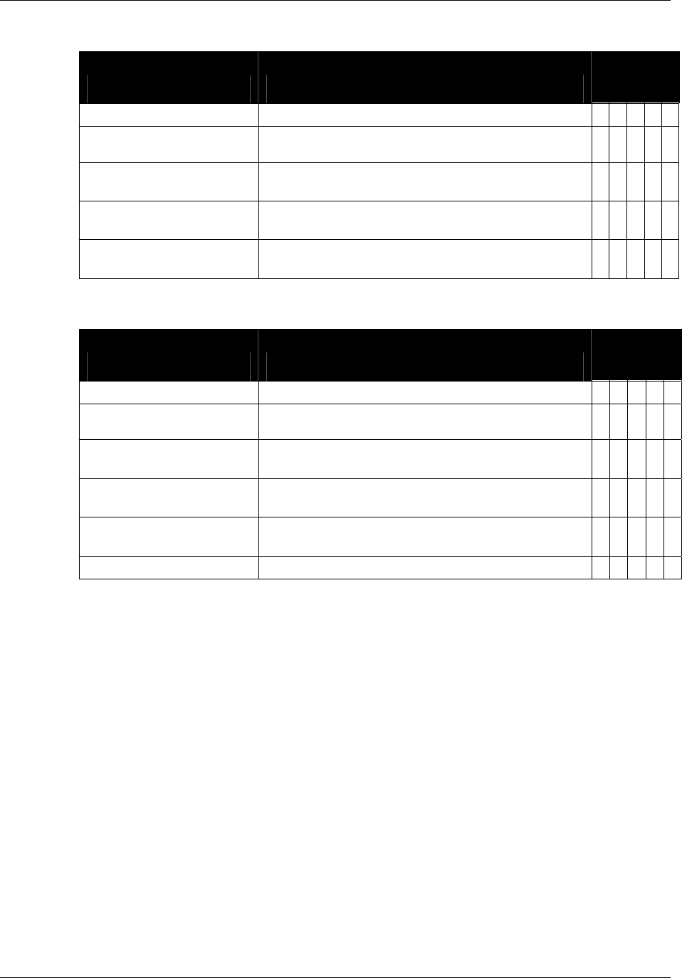
CHAPTER 4 ALIEN READER PROTOCOL
READER INTERFACE GUIDE
DOC. CONTROL # 8101938-000 REV 05
31
EXTERNAL IO COMMANDS
Command Description
9800
9780
8780
9640
9770
get ExternalInput Get the External Input pin values. ✔✔✔✔
get ExternalOutput
set ExternalOutput
Get and Set the External Output pin values. ✔✔✔✔
get InitExternalOutput
set InitExternalOutput
Get and Set the External Output state the apply during
and after the reader boots. ✔✔✔✔
get InvertExternalOutput
set InvertExternalOutput
Turn on or off inversion of the External Outputs. When
inverted, setting an output high drives its voltage low. ✔✔✔✔
get InvertExternalInput
set InvertExternalInput
Turn on or off inversion of the External Inputs. When
inverted, driving an input voltage high indicates low. ✔✔✔✔
TAGLIST COMMANDS
Command Description
9800
9780
8780
9640
9770
get TagList (t) Get the current list of active tags from the reader. ✔✔✔✔✔
get PersistTime
set PersistTime
Get and Set the persistence time for tags in the
TagList. ✔✔✔✔✔
get TagListFormat
set TagListFormat
Set and Get the format for TagLists. ✔✔✔✔✔
get TagListAntennaCombine
set TagListAntennaCombine
Specify whether to combine reads of a tag from
different antennas into one TagList entry. ✔✔✔✔✔
get TagListCustomFormat
set TagListCustomFormat
Specify a custom format for text based TagLists. ✔✔✔✔✔
Clear TagList Clear the list of active tags on the reader. ✔✔✔✔✔

ALIEN READER PROTOCOL CHAPTER 4
READER INTERFACE GUIDE
DOC. CONTROL # 8101938-000 REV 05
32
ACQUISITION COMMANDS
Command Description
9800
9780
8780
9640
9770
get AcquireMode
set AcquireMode
Specify how the RFID Reader reads tags. ✔✔✔✔✔
get AcqCycles
set AcqCycles
Specify the number of acquisition cycles to perform
during each Class1/Gen1 tag read action. ✔✔✔✔
get AcqCount
set AcqCount
Specify the number of reads to perform in each
Class1/Gen1 read cycle. ✔✔✔✔
get AcqEnterWakeCount
set AcqEnterWakeCount
Specify the number of times to Wake tags before each
Class1/Gen1 acquisition cycle. ✔✔✔✔
get AcqExitWakeCount
set AcqExitWakeCount
Specify the number of times to Wake tags at the end of
each Class1/Gen1 acquisition cycle. ✔✔✔✔
get AcqSleepCount
set AcqSleepCount
Specify the number of times Class1/Gen1 tags are
slept, as they are read. ✔✔✔✔
get AcqC1Cycles
set AcqC1Cycles
Same as AcqCycles. ✔
get AcqC1Count
set AcqC1Count
Same as AcqCount. ✔
get AcqC1EnterWakeCount
set AcqC1EnterWakeCount
Same as AcqEnterWakeCount. ✔
get AcqC1ExitWakeCount
set AcqC1ExitWakeCount
Same as AcqExitWakeCount. ✔
get AcqC1SleepCount
set AcqC1SleepCount
Same as AcqSleepCount. ✔
get AcqG2Cycles
set AcqG2Cycles
Specify the number of acquisition cycles to perform
during each Class1/Gen2 tag read action. ✔
get AcqG2Count
set AcqG2Count
Specify the number of reads to perform in each
Class1/Gen2 read cycle. ✔
get AcqG2Q
set AcqG2Q
Specify the starting "Q" value to use in each
Class1/Gen2 read cycle. ✔
get AcqC0Cycles
set AcqC0Cycles
Specify the number of acquisition cycles to perform
during each Class0 tag read action. ✔
get AcqC0Count
set AcqC0Count
Specify the number of reads to perform in each Class0
read cycle. ✔
get TagType
set TagType
Get and Set a flag indicating which tag types to look for
– may improve reader performance. ✔✔✔✔✔
Wake Wake tags addressed by the Mask settings ✔✔✔✔
Sleep Sleep tags addressed by the Mask settings ✔✔✔✔
get Mask
set Mask
Get and Set the current tag mask as an array of bytes.
ALR-9800 also accepts "AcqMask". ✔✔✔✔

CHAPTER 4 ALIEN READER PROTOCOL
READER INTERFACE GUIDE
DOC. CONTROL # 8101938-000 REV 05
33
AUTONOMOUS MODE COMMANDS
Command Description
9800
9780
8780
9640
9770
get AutoMode
set AutoMode
Switch auto mode on and off. ✔✔✔✔✔
get AutoWaitOutput
set AutoWaitOutput
Specify the value of the output pins while in wait mode. ✔✔✔✔
get AutoStartTrigger
set AutoStartTrigger
Get and Set the trigger that sends the auto mode state
into working state. ✔✔✔✔
get AutoStartPause
set AutoStartPause
Get and Set the time to wait after receiving a start
trigger before starting AutoMode ✔
get AutoWorkOutput
set AutoWorkOutput
Specify the value of the output pins while in work mode. ✔✔✔✔
get AutoAction
set AutoAction
Get and Set the action to perform in auto mode. ✔✔✔✔
get AutoStopTrigger
set AutoStopTrigger
Set and Get the external trigger that will move the auto
mode state from work mode to evaluate mode. ✔✔✔✔
get AutoStopTimer
set AutoStopTimer
Set and Get the timer that will move the auto mode
state from work mode to evaluate mode. ✔✔✔✔ *
get AutoTrueOutput
set AutoTrueOutput
Specify the value of the output pins when the auto
mode evaluation returns a True condition. ✔✔✔✔
get AutoTruePause
set AutoTruePause
Set and Get the pause time after the auto mode
evaluation returns a True condition. ✔✔✔✔
get AutoFalseOutput
set AutoFalseOutput
Specify the value of the output pins when the auto
mode evaluation returns a False condition. ✔✔✔✔
get AutoFalsePause
set AutoFalsePause
Set and Get the pause time after the auto mode
evaluation returns a False condition. ✔✔✔✔
AutoModeTriggerNow Force a trigger event to occur. ✔✔✔✔
AutoModeReset Reset all auto mode values to their default states. ✔✔✔✔✔
get AutoModeStatus Get the current status of auto mode. ✔✔✔
* The ALR-9770 also uses the AutoStopTimer value as a time limit on individual
read operations. See the AutoStopTimer discussion on the following pages for
more information.

ALIEN READER PROTOCOL CHAPTER 4
READER INTERFACE GUIDE
DOC. CONTROL # 8101938-000 REV 05
34
NOTIFY MODE COMMANDS
Command Description
9800
9780
8780
9640
9770
get NotifyMode
set NotifyMode
Switch notify mode on and off. ✔ ✔ ✔ ✔
get NotifyFormat
set NotifyFormat
Get and Set the format for TagLists pushed out in notify
mode. ✔ ✔ ✔ ✔
get NotifyHeader
set NotifyHeader
Turns on and off the additional header (and footer) lines
in notification messages. ✔ ✔ ✔ ✔
get NotifyAddress
set NotifyAddress
Get and Set the address to push TagLists to. ✔✔✔✔
get NotifyTime
set NotifyTime
Get and Set the time interval for automatically pushing
TagLists. ✔✔✔✔
get NotifyTrigger
set NotifyTrigger
Get and Set the trigger for pushing TagLists. ✔✔✔✔
get NotifyKeepAliveTime
set NotifyKeepAliveTime
The amount of time the reader keeps it's notification
TCP socket open without communication activity. ✔✔✔
get MailServer
set MailServer
Set and Get an SMTP mail server. This is only required
if notification email messages are sent out. ✔✔✔✔
get MailFrom
set MailFrom
Set and Get the email address of the RFID Reader. ✔✔✔✔
get NotifyRetryCount
set NotifyRetryCount
Get and Set the number of times a failed network
notification is repeated. ✔✔✔✔
get NotifyRetryPause
set NotifyRetryPause
Get and Set the delay between failed network
notification retries. ✔✔✔✔
NotifyNow Force a message via the notification system. ✔✔✔✔
The following sections describe each command category - detailing each
command, its use and the response formats.
NOTE: RFID Reader commands are not case sensitive, that is, you can use
upper or lower case, or any combination thereof, and the reader will understand
the command. Capitalization of commands is used in this document and in actual
command responses solely for the purpose of readability.
General Commands
General commands cover basic reader, antenna functions and help &
information.
Help (h)
9800 | 9780 | 8780 | 9640 | 9774
This command lists all reader commands available. You may also type just the
letter “h” to send this command.

CHAPTER 4 ALIEN READER PROTOCOL
READER INTERFACE GUIDE
DOC. CONTROL # 8101938-000 REV 05
35
Info (i)
9800 | 9780 | 8780 | 9640 | 9774
This provides a list of current reader settings. You may also type just the letter “i”
to send this command.
!
9800 | 9780 | 8780 | 9640 | 9774
This command (exclamation mark) asks the reader to repeat the last command
issued.
Save
9800 | 9780 | 8780 | 9640 | 9774
The Save command writes the current settings to flash memory. This ensures
that if the reader loses power it will restart in the same state.
Save Example
Command
Response
>Save
All settings have been saved to flash!
Q (Quit)
9800 | 9780 | 8780 | 9640 | 9774
(For Telnet operation only) The Quit command allows you to exit the current
Telnet session.
Function
9800 | 9780 | 8780 | 9640 | 9774
The standard operating mode of a reader is to read tags. Additional functionality
exists in the reader to program, lock, erase, and kill tags, but these functions
must first be enabled. This is done by changing the reader's "Function" attribute
from "Reader" to "Programmer". Doing so enables these additional programming
commands, as can be evidenced by observing the new programming commands
in the Help display (see above).
To once again disable the programming commands, change the "Function"
attribute back to "Reader".
Function Examples
Command
Response
>get Function
Function = Reader
Command
Response
>set Function = Programmer
Function = Programmer
Command
Response
>set Function = Reader
Function = Reader

ALIEN READER PROTOCOL CHAPTER 4
READER INTERFACE GUIDE
DOC. CONTROL # 8101938-000 REV 05
36
ReaderName
9800 | 9780 | 8780 | 9640 | 9774
The reader can be assigned an arbitrary text name to aid identification in
multiple-reader environments. This name can be retrieved and changed at any
time throughout reader operation.
ReaderName Examples
Command
Response
>get ReaderName
ReaderName = My First Alien Reader
Command
Response
>set ReaderName = My Second Alien Reader
ReaderName = My Second Alien Reader
ReaderType
9800 | 9780 | 8780 | 9640 | 9774
The reader type can be retrieved using this command. The resulting text will be a
single-line reply describing the model number of the reader and related
information.
ReaderType Example
Command
Response
>get ReaderType
ReaderType = Alien RFID Tag Reader, Model: ALR-9780
(Four Antenna / Class 1 / 915 MHz)
Command
Response
>get ReaderType
ReaderType = Alien RFID Tag Reader, Model: ALR-9800
(Four Antenna / Multi-Protocol / 915 MHz)
ReaderVersion
9800 | 9780 | 8780 | 9640 | 9774
The reader version can be retrieved using this command. The resulting text is a
multi-line reply. Each line of the reply describes the version number of a major
reader component, as well as some additional locality information.
This command is not available when AutoMode is on. The reader
responds with "Error 27: Invalid context. Command cannot be issued
while AutoMode is ON".
ReaderVersion Example
Command
Response
>get ReaderVersion
Ent. SW Rev: 3.2.02
Country Code: 01, Reader Type: 03, Firmware Rev: 2.2.21
Command
Response
>get ReaderVersion (ALR-9770)
ReaderVersion = Firmware Rev: 2.1.12 (Alien Technology
v1.04.04, 02/14/05)
OS Version: Linux 2.4.22-uc0 2005-01-26T12:00:35-0500

CHAPTER 4 ALIEN READER PROTOCOL
READER INTERFACE GUIDE
DOC. CONTROL # 8101938-000 REV 05
37
ReaderNumber
9800 | 9780 | 8780 | 9640 | 9774
The reader can be assigned an arbitrary number to aid identification in multiple-
reader environments. This number can be retrieved and changed at any time
throughout reader operation.
Allowed values for ReaderNumber are 1-255.
The default ReaderNumber value is 255.
ReaderNumber Examples
Command
Response
>get ReaderNumber
ReaderNumber = 255
Command
Response
>set ReaderNumber = 15
ReaderNumber = 15
Uptime
9800 | 9780 | 8780 | 9640 | 9774
The Uptime command returns the elapsed time, in seconds, since the last time
the reader was rebooted.
Uptime Example
Command
Response
>get Uptime
Uptime (secs) = 702048
Username
9800 | 9780 | 8780 | 9640 | 9774
The reader can be operated over the network. When operated in this mode it
uses a simple username/password authentication scheme to stop unwelcome
visitors accessing it. This command allows the username to be defined and
obtained.
A username/password pair is not required when operating the reader via
serial connection.
The default username setting is “alien” NOTE: The username is case
sensitive and must be entered in all lowercase.
Username Examples
Command
Response
>get Username
Username = alien
Command
Response
>set Username = hal
Username = hal
Password
9800 | 9780 | 8780 | 9640 | 9774
The reader can be operated over the network. When operated in this mode it
uses a simple username/password authentication scheme to stop unwelcome

ALIEN READER PROTOCOL CHAPTER 4
READER INTERFACE GUIDE
DOC. CONTROL # 8101938-000 REV 05
38
visitors accessing it. This command allows the password to be defined and
obtained.
A username/password pair is not required when operating the reader via
serial connection.
The default password setting is “password” NOTE: The password is case
sensitive and must be entered in all lowercase.
Password Examples
Command
Response
>get Password
Password = password
Command
Response
>set Password = 1234fab
Password = 1234fab
MaxAntenna
9800 | 9780 | 8780 | 9640 | 9774
To determine the maximum addressible antenna port of the reader, use the get
MaxAntenna command. Antenna ports are numbered starting at zero, so the
actual number of ports is one more than the MaxAntenna value. A reader with
four antenna ports returns a MaxAntenna of 3. Similarly, a reader with only two
antenna ports returns a MaxAntenna of 1.
This command is not available when AutoMode is on. The reader
responds with "Error 27: Invalid context. Command cannot be issued
while AutoMode is ON".
MaxAntenna Example
Command
Response
>get MaxAntenna
MaxAntenna = 3
AntennaSequence
9800 | 9780 | 8780 | 9640 | 9774
The reader can support the use of multiple antennas. This command allows the
user to select which antenna port(s) to use and in what sequence.
If using only one antenna, you will assign just one antenna port
number.
To instruct the reader to cycle through the antenna list during tag
reads, enter the port designations for all antennas to be used and the
order in which they should be used.
Multiple antennas are specified by passing in a comma-separated list
as the argument. The default AntennaSequence is 0.
This command is not available when AutoMode is on. The reader
responds with "Error 27: Invalid context. Command cannot be issued
while AutoMode is ON".
Multi-Static antenna readers, such as the ALR-9800 and newer ALR-
8780 readers pair up two antennas as send/receive pairs - #0 and #1
form one antenna pair, and #2 and #3 form another pair. In these cases,

CHAPTER 4 ALIEN READER PROTOCOL
READER INTERFACE GUIDE
DOC. CONTROL # 8101938-000 REV 05
39
the antenna number specified in the AntennaSequence is always the
transmit antenna. The receive antenna is taken to be the remaining
antenna of the pair.
The ALR-9770 reader recognizes only those antennas that are present
when the reader boots up. If the antenna configuration is changed, the
ALR-9770 must be restarted before it will be aware of the new
configuration.
AntennaSequence Examples
Command
Response
>get AntennaSequence
AntennaSequence = 0
To always use antenna 1:
Command
Response
>set AntennaSequence = 1
AntennaSequence = 1
To cycle between
antenna 0 and antenna 1:
Command
Response
>set AntennaSequence = 0, 1
AntennaSequence = 0, 1
To weight antenna 0 more
than antenna 1:
Command
Response
>set AntennaSequence = 0, 0, 0, 1
AntennaSequence = 0, 0, 0, 1
RFAttenuation
9800 | 9780 | 8780 | 9640 | 9774
Alien RFID readers output 1 watt of RF power at each antenna. While this power
is sufficient to provide good penetration and range, these attributes are not
always desireable. If multiple readers are in the same vicinity, their signals may
interfere with each other. Also, in situations where tagged product is close
together, but only on product should be read at a time (a conveyor belt, for
example), then penetrating power and long range are your enemies.
Attenuating RF reduces its power, and there are two ways to do this. The first
method involves placing attenuators inline in the antenna cable. This method is
quick but is not flexible and, more importantly, reduces both the emitted RF
power as well as the return signal from the tag, which is already very weak. This
would impair the reader's ability to detect tags.
The second method uses software-controlled digital attenuation, built into Alien
readers. Using the software-controlled digital attenuation reduces the emitted
power but not the return signal. The RFAttenuation value ranges from 0 (no
attenuation, maximum power) to 160 (maximum attenuation, minimum power), in
increments of 10 - each "decade" representing an additional 1 dB of RF
attenuation.
The default value for RFAttenuation is 0.
RFAttenuation can range from 0 to 160.
Increasing RFAttenuation by 10 reduces RF power by 1 dB.
Changes take effect immediately.

ALIEN READER PROTOCOL CHAPTER 4
READER INTERFACE GUIDE
DOC. CONTROL # 8101938-000 REV 05
40
RFAttenuation Examples
Command
Response
>get RFAttenuation
RFAttenuation = 0
Command
Response
>set RFAttenuation = 30
RFAttenuation = 30
FactorySettings
9800 | 9780 | 8780 | 9640 | 9774
The FactorySettings command will reset all reader settings to their factory default
values, and then reboot the reader. The reboot is required in order for the new
settings (especially network values) to take effect.
FactorySettings Examples
Command
Response
>FactorySettings
All settings have been reset !
Rebooting System...
Reboot
9800 | 9780 | 8780 | 9640 | 9774
The Reboot command causes the reader to immediately close all network
connections and reboot.
It is recommended that you reboot the reader any time network
configuration parameters are changed.
The ALR-9770 reader may also be rebooted via its web interface.
Browse to the reader’s IP address in a web browser, click the Restart link
on the left side of the page and follow the provided instructions.
Reboot Examples
Command
Response
>Reboot
Rebooting System...

CHAPTER 4 ALIEN READER PROTOCOL
READER INTERFACE GUIDE
DOC. CONTROL # 8101938-000 REV 05
41
Network Configuration Commands
These commands allow you to configure and retrieve settings related to reader
communications with the network.
MACAddress
9800 | 9780 | 8780 | 9640 | 9774
The MAC (Media Access Control) Address is a unique, hardcoded value that
identifies each device with a network interface. The reader's MAC Address can
be retrieved with the get MACAddress command.
The value returned is a sequence of six hex bytes, separated by colons.
MACAddress Example
Command
Response
>get MACAddress
MACAddress = 00:90:c2:c3:14:38
DHCP
9800 | 9780 | 8780 | 9640 | 9774
The reader supports automatic network configuration using the widely available
DHCP protocol. If DHCP is available at the reader installation site, this protocol
can be switched on. If DHCP is not available or not desired the use of this
protocol can be switched off.
Valid command parameters are ON and OFF.
The default setting is ON.
After making changes with this command, you must save and reboot the
reader to implement the changes.
DHCP Examples
Command
Response
>get DHCP
DHCP = ON
Command
Response
>set DHCP = OFF
DHCP = OFF
IPAddress
9800 | 9780 | 8780 | 9640 | 9774
If DHCP is not used for automatic configuration, the reader must be manually
configured for use on a network. The IPAddress command allows you to assign
and retrieve the host’s IP address.
DHCP must be off in order to change the IPAddress.
After making changes with this command, you must save and reboot the
reader to implement the changes.
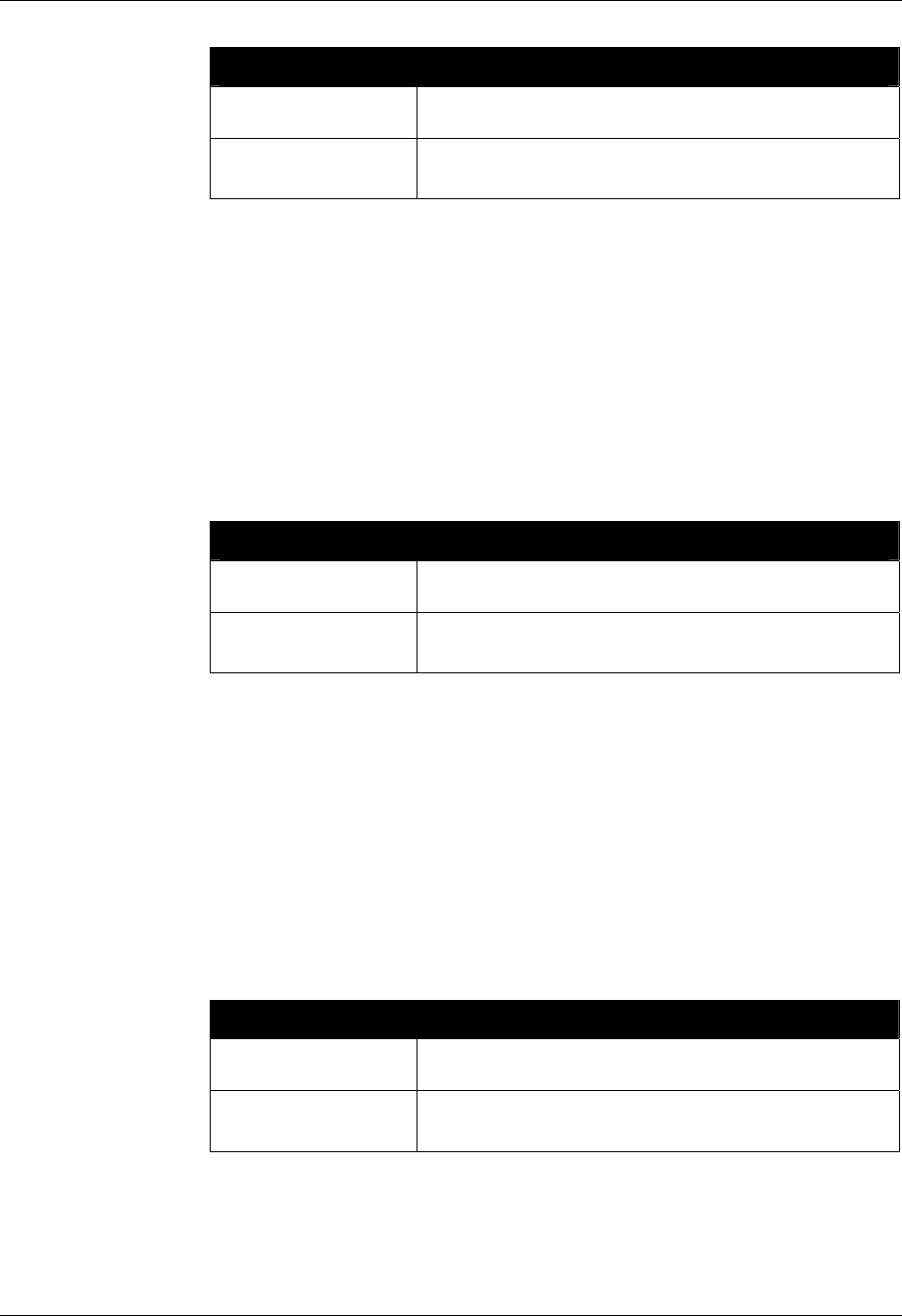
ALIEN READER PROTOCOL CHAPTER 4
READER INTERFACE GUIDE
DOC. CONTROL # 8101938-000 REV 05
42
IPAddress Examples
Command
Response
>get IPAddress
IPAddress = 12.34.56.78
Command
Response
>set IPAddress =34.55.33.12
IPAddress = 34.55.33.12
Gateway
9800 | 9780 | 8780 | 9640 | 9774
If DHCP is not used for automatic configuration, the reader must be manually
configured for use on a network. The gateway command allows the network
gateway to be assigned and retrieved.
Gateway must be specified as a numerical IP address.
DHCP must be off in order to change the Gateway.
After making changes with this command, you must save and reboot the
reader to implement the changes.
Gateway Examples
Command
Response
>get Gateway
Gateway = 34.56.78.90
Command
Response
>set Gateway=12.56.23.01
Gateway = 12.56.23.01
Netmask
9800 | 9780 | 8780 | 9640 | 9774
If DHCP is not used for automatic configuration, the reader must be manually
configured for use on a network. The subnet mask command pair allow the
subnet mask to be assigned and retrieved.
A subnet mask must be specified as a numerical IP address.
DHCP must be off in order to change the Netmask.
After making changes with this command, you must save and reboot the
reader to implement the changes.
Netmask Examples
Command
Response
>get Netmask
Netmask = 255.255.255.128
Command
Response
>set Netmask=255.255.255.0
Netmask = 255.255.255.0

CHAPTER 4 ALIEN READER PROTOCOL
READER INTERFACE GUIDE
DOC. CONTROL # 8101938-000 REV 05
43
DNS
9800 | 9780 | 8780 | 9640 | 9774
If DHCP is not used for automatic configuration, the reader must be manually
configured for use on a network. The DNS command pair allow the DNS server
location to be assigned and retrieved.
A DNS server must be specified as a numerical IP address.
DHCP must be off in order to change the DNS.
After making changes with this command, you must save and reboot the
reader to implement the changes.
DNS Examples
Command
Response
>get DNS
DNS = 12.34.56.78
Command
Response
>set DNS=45.224.124.34
DNS = 45.224.124.34
NetworkTimeout
9800 | 9780 | 8780 | 9640 | 9774
When the reader receives a command on its Command port, it opens a TCP
socket and waits for data to arrive. If inbound communication ceases, rather than
hold the socket open indefinitely the reader waits a period of time then
automatically closes the connection, ignoring any partial command it may have
already received. This time period is the NetworkTimeout.
The NetworkTimeout is specified in seconds
The default value is 90 seconds
NOTE: Changes made with this command will take effect immediately.
NetworkTimeout Examples
Command
Response
>get NetworkTimeout
NetworkTimeout = 90
Command
Response
>set NetworkTimeout = 120
NetworkTimeout = 120
Example Behavior
(using Telnet)
>set NetworkTimeout = 5
NetworkTimeout = 5
>(wait more than 5 seconds)
Connection Timeout.
Closing Connection…Bye!
(Telnet session ends)

ALIEN READER PROTOCOL CHAPTER 4
READER INTERFACE GUIDE
DOC. CONTROL # 8101938-000 REV 05
44
CommandPort
9800 | 9780 | 8780 | 9640 | 9774
The reader can be configured and operated over the network using standard
network sockets. The CommandPort settings are used to assign and retrieve the
exact port number used by the reader for this network connectivity.
The default setting for this command is 23 (the standard Telnet port)
Changes to this setting do not affect serial communication and/or Web
communication with the reader.
CommandPort Examples
Command
Response
>get CommandPort
CommandPort = 23
Command
Response
>set CommandPort=10004
CommandPort = 10004
HeartbeatPort
9800 | 9780 | 8780 | 9640 | 9774
The reader can be configured to periodically send out a heartbeat message to
the network. This heartbeat takes the form of a single UDP packet (Universal
Datagram Packet) broadcast out to the entire subnet or a particular address.
The Set HeartbeatPort command allows you to configure the actual port number
that this packet is sent out to.
Listening for this heartbeat can be used to initially locate a reader on a network
and subsequently make sure that the reader is still alive.
The default port setting for this command is 3988
Changes made with this command take effect immediately.
The format of the UDP packet is a single XML document detailing the reader:
<Alien-RFID-Reader-Heartbeat>
<ReaderName>Alien RFID Reader</ReaderName>
<ReaderType>
Alien RFID Tag Reader, Model: ALR-9780
(Four Antenna / Class 1 / 915Mhz)
</ReaderType>
<IPAddress>10.1.60.5</IPAddress>
<CommandPort>23</CommandPort>
<HeartbeatTime>30</HeartbeatTime>
</Alien-RFID-Reader-Heartbeat>

CHAPTER 4 ALIEN READER PROTOCOL
READER INTERFACE GUIDE
DOC. CONTROL # 8101938-000 REV 05
45
HeartbeatPort Examples
Command
Response
>get HeartbeatPort
HeartbeatPort = 3004
Command
Response
>set HeartbeatPort=10002
HeartbeatPort = 10002
HeartbeatTime
9800 | 9780 | 8780 | 9640 | 9774
The reader can be configured to periodically send out a heartbeat message to
the network. This heartbeat takes the form of a single UDP packet (Universal
Datagram Packet) broadcast out to the entire subnet or a particular address.
The time interval between heartbeats can be assigned and retrieved using this
command.
All intervals are specified in seconds.
A setting of zero (seconds) will suspend the output of any further
heartbeats.
The default setting for this command is 30 seconds.
Changes made with this command take effect immediately.
HeartbeatTime Examples
Command
Response
>get HeartbeatTime
HeartbeatTime = 30
Command
Response
>set HeartbeatTime=60
HeartbeatTime = 60
HeartbeatAddress
9800 | 9780 | 8780 | 9640 | 9774
The reader can be configured to periodically send out a heartbeat message to
the network. This heartbeat takes the form of a single UDP packet (Universal
Datagram Packet) broadcast out to the entire subnet or a particular address.
The address of the host to receive these packets is defined by the
HeartbeatAddress command.
The default value 255.255.255.255 is a special "multicast" address,
which enables all devices on the subnet to receive the packets.
Changes made with this command take effect immediately.
ALIEN READER PROTOCOL CHAPTER 4
READER INTERFACE GUIDE
DOC. CONTROL # 8101938-000 REV 05
46
HeartbeatAddress Examples
Command
Response
>get HeartbeatAddress
HeartbeatAddress = 255.255.255.255
Command
Response
>set HeartbeatAddress =10.1.70.17
HeartbeatAddress = 10.1.70.17
HeartbeatCount
9800 | 9780 | 8780 | 9640 | 9774
The HeartbeatCount property specifies how many heartbeat messages the
reader broadcasts after it boots. After this point the reader stops sending
heartbeat messages until the HeartbeatCount is changed, or the reader is
rebooted.
The range of values for HeartbeatCount is –1 to 65535.
The default value of –1 indicates that the reader should send heartbeat
messages indefinitely.
HeartbeatAddress Examples
Command
Response
>get HeartbeatCount
HeartbeatCount = -1
Command
Response
>set HeartbeatCount = 5
HeartbeatCount = 5
Time Commands
The time at which tags are read by a reader is particularly important for many
applications. For this reason, the reader has three time commands to ensure that
the onboard real-time clock is always set accurately.
TimeServer
9800 | 9780 | 8780 | 9640 | 9774
The reader uses the Internet to accurately set its internal clock every time it is
rebooted. The protocol it uses is called the Daytime Protocol (RFC-867) which
typically returns the time in UTC format.
In order to use this feature, a TimeServer must be specified. This is the network
address of a machine that is constantly running the Daytime Protocol. In the US
there are a number of machines owned and operated by the Government
explicitly providing the time and date to Internet users.
By default the reader is configured to connect to one of these machines
on boot-up to get the current time.
For a more in-depth description of this server, and a list of other publicly
accessible Daytime Protocol Servers, see:
http://www.boulder.nist.gov/timefreq/service/its.htm

CHAPTER 4 ALIEN READER PROTOCOL
READER INTERFACE GUIDE
DOC. CONTROL # 8101938-000 REV 05
47
The default setting for this command is 132.163.4.101, a primary NIST
network time server. Some alternative time servers are:
time-a.nist.gov / 129.6.15.28
time-b.nist.gov / 129.6.15.29
time.nist.gov / 192.43.244.18
After making changes with this command, you must save and reboot the
reader to implement the changes.
TimeServer Examples
Command
Response
>get TimeServer
TimeServer = 129.6.15.28
Command
Response
>set TimeServer = 129.6.15.28
TimeServer = 129.6.15.28
TimeZone
9800 | 9780 | 8780 | 9640 | 9774
These commands allow the current time zone to be assigned to or retrieved from
the reader. The time zone specifies the number of hours that must be added to or
subtracted from UTC (Coordinated Universal Time; also known as GMT or Zulu)
to determine a local time reference.
For example, to convert from UTC to Pacific Standard Time, set the TimeZone to
–8. To convert from UTC to Pacific Daylight Time, set the TimeZone to –7.
The default setting for this command is -7 hours (Pacific Daylight Time)
because PDT is UTC time minus 7 hours.
For more information about time zones, servers and UTC, refer to the
Website listed under the Get/Set TimeServer command.
Changes made with this command will take effect immediately.
The TimeZone parameter is only useful if the TimeServer is used to automatically
set the system clock. In this case, the TimeServer always retrieves the time in
UTC format and will need to be offset to reflect local time using this parameter.
TimeZone Examples
Command
Response
>get TimeZone
TimeZone = -8
Command
Response
>set TimeZone = 3
TimeZone = 3
The TimeServer is only used once when the reader is booted up. A message in
the boot sequence (sent out to the serial console) indicates success or failure of
this option.
For example, a successful boot sequence will report the following messages to
the serial console:

ALIEN READER PROTOCOL CHAPTER 4
READER INTERFACE GUIDE
DOC. CONTROL # 8101938-000 REV 05
48
Booting Alien RFID Reader
Boot> Boot Level 1 (Console Communication) : Success
Boot> Boot Level 2 (Reader Communication) : Success
Boot> Boot Level 3 (Command Set) : Success
Boot> Boot Level 4 (Tag Manager) : Memory for 1000 Tags
Boot> Boot Level 5 (Initializing Network Interface) : ...
Boot> Boot Level 6 (Network) : Success - IP Address is 10.1.60.114
Boot> Boot Level 7 (Telnet Interface) : Success - Port 23 Ready
Boot> Boot Level 8 (Network Time Service) : Success - Time Set to
2003/12/04 12:32:59
Boot> Ready
Time
9800 | 9780 | 8780 | 9640 | 9774
These commands allow the current time to be assigned to or retrieved from the
reader.
Times used by this command are always specified in local time, as
defined by the TimeZone command.
Times are always specified by the format YYYY/MM/DD hh:mm:ss.
Changes made with this command will take effect immediately.
Time Examples
Command
Response
>get Time
Time = 2002/6/3 9:23:01
Command
Response
>set Time = 2002/6/3 19:23:01
Time = 2002/6/3 19:23:01
External I/O Commands
These commands allow you to configure and retrieve data from the reader’s
external input/output pins.
ExternalInput
9800 | 9780 | 8780 | 9640 | 9774
The reader monitors four external input pins, which can subsequently be
controlled by external proximity detectors and other input devices such as
“magic-eyes” and magnetic switches. This command allows these external input
pin values to be obtained. Please refer to the Hardware Setup Guide for pinout
diagrams.
The command returns a single byte result that represents the bitmap of
the external input pin states. Bit 0 represents the state of input #1, bit 1
represents the state of input #2, etc.
The ALR-9640's input states are inverted, as compared to the other fixed
readers. This can be rectified by using the InvertExternalInput command.

CHAPTER 4 ALIEN READER PROTOCOL
READER INTERFACE GUIDE
DOC. CONTROL # 8101938-000 REV 05
49
ExternalInput Examples
Command
Response
>get ExternalInput
ExternalInput = 2 (i.e., binary "10")
ExternalOutput
9800 | 9780 | 8780 | 9640 | 9774
The reader controls four external output pins, which can subsequently be used to
control external devices such a doors/gates, security lights, etc. Please refer to
the Hardware Setup Guide for pinout diagrams.
With this command you can get or set the external output pin states. The single
parameter/return value is an integer bitmap representing the states of the
external output pins.
Bit 0 represents the state of output #1, bit 1 represents the state of
output #2, etc.
For example, to set pin 1 to high and pin 0 on low, use the bitmap of
2decimal, which translates to 10binary.
The ALR-9640's output states are inverted, as compared to the other
fixed readers. This can be rectified by using the InvertExternalOutput
command.
ExternalOutput Examples
Command
Response
>set ExternalOutput = 2
ExternalOutput = 2
Command
Response
>get ExternalOutput
ExternalOutput = 2
InitExternalOutput
9800 | 9780 | 8780 | 9640 | 9774
When the reader is powered up, it sets the external output pins to states defined
by the InitExternalOutput attribute. This gives you the flexibility to choose which
output pins should default to high, and which output pins should default to low – a
very important consideration if there are mechanical devices controlled by the
readers I/O port.
With this command you can get or set the initial external output pin states. The
single parameter/return value is an integer bitmap representing the states of the
external output pins during and after a startup.
Bit 0 represents the desired state of output #1, bit 1 represents the
desired state of output #2, etc.
For example, to set pin 1 to high and pin 0 on low, use the bitmap of
2decimal, which translates to 0010binary.
Changes made with this command take effect during the next reboot.
The bitmap that you specify is applied directly to the outputs upon
startup, without any inversion that may have been set with
InvertExternalOutput.

ALIEN READER PROTOCOL CHAPTER 4
READER INTERFACE GUIDE
DOC. CONTROL # 8101938-000 REV 05
50
InitExternalOutput Examples
Command
Response
>set InitExternalOutput = 7 (0111binary = #1, 2, 3 high, #4 low)
InitExternalOutput = 7
Command
Response
>get InitExternalOutput
InitExternalOutput = 7
InvertExternalInput
9800 | 9780 | 8780 | 9640 | 9774
In the default configuration, a high voltage applied to an externa input results in
an external input reading of "1", or "on". Depending on the electronics of the
connected device, a high voltage applied to the pin may actually be the result of
the device being "inactivate" instead of "activate". To accommodate this case and
avoid possible confusion when examining bitmaps of external input states,
turning on InvertExternalInput reverses the "sense" of all the external inputs,
effectively resulting an external input value to be "1" when the pin voltage is
driven low, and vice versa..
Valid command values are ON and OFF.
The default setting is OFF.
InvertExternalInput Examples
Command
Response
>get ExternalInput
ExternalInput = 0
Command
Response
>set InvertExternalInput = ON
InvertExternalInput = ON
Command
Response
>get InvertExternalInput
InvertExternalInput = ON
Command
Response
>get ExternalInput
ExternalInput = 15 (inverted value - inputs haven't changed)
InvertExternalOutput
9800 | 9780 | 8780 | 9640 | 9774
In the default configuration, setting an external output to "1", or "on", causes the
voltage on that output pin to go high. Depending on the electronics of the
connected device, a high voltage on the pin may cause that device to "activate"
or vice versa. To accommodate this case and avoid possible confusion when
specifying bitmaps of desired external output states, turning on
InvertExternalOutput reverses the "sense" of all the external outputs, effectively
causing to pin voltage to go high when the external output is set to "0", and vice
versa.
Valid command values are ON and OFF.
The default setting is OFF.
When ON, the inversion of output states is applied both in setting and
getting the pin states. It is therefore a transparent change, unless test the
voltage on the output pins.

CHAPTER 4 ALIEN READER PROTOCOL
READER INTERFACE GUIDE
DOC. CONTROL # 8101938-000 REV 05
51
The state of InvertExternalOutput has no effect on the InitExternalOutput
during bootup. The pin state defined by InitExternalOutput is applied to
the output pins regardless of the InvertExternalOutput setting.
InvertExternalOutput Examples
Command
Response
>get ExternalOutput
ExternalOutput = 0
Command
Response
>set InvertExternalOutput = ON
InvertExternalOutput = ON
Command
Response
>get InvertExternalOutput
InvertExternalOutput = ON
Command
Response
>get ExternalOutput
ExternalOutput = 15 (inverted value - outputs haven't changed)
TagList Commands
TagList commands allow you to retrieve immediate listings of tags that have
been read and saved by the reader, and to assign and retrieve TagList functional
parameters.
Get TagList (t)
9800 | 9780 | 8780 | 9640 | 9774
You can retrieve the reader’s stored TagList with the Get TagList command.
The maximum number of tags that can be stored in the TagList is 6000
for the ALR-9800, and 1000 for all other models.
"Get TagList" and "t" can be used interchangeably.
Using the Get TagList to retrieve the stored list only once:
If the reader is not in Autonomous Mode, the reader immediately
performs a full tag search (read and report) and displays its current
internal TagList. The reply is a multi-line response, with each line listing
an active tag. If the TagList is empty, the message “(No Tags)” is
returned.
If the reader is in Autonomous Mode, the reader just returns its
current internal TagList.
The format of the data returned by this command is specified using the Set
TagListFormat command, described below.

ALIEN READER PROTOCOL CHAPTER 4
READER INTERFACE GUIDE
DOC. CONTROL # 8101938-000 REV 05
52
TagList Examples
Command
Response
>get TagList
Tag:8000 8004 0000 003B, Disc:2003/12/04 12:35:11,
Last:2003/12/04 12:35:11, Count:3, Ant:0
Tag:8000 8004 9999 0004, Disc:2003/12/04 12:35:11,
Last:2003/12/04 12:35:11, Count:3, Ant:0
Command
Response
>get TagList
(No Tags)
PersistTime
9800 | 9780 | 8780 | 9640 | 9774
The PersistTime specifies the length of time a tag’s data will remain in the
reader’s internal list of active tags.
Persist times are specified in seconds.
Setting the persist time to a positive number (1-n) establishes a persist
time of the desired number of seconds
A zero persist time (0) guarantees that tags are not stored in the TagList.
However issuing a get TagList command in Interactive Mode
returns any tags immediately found even though they won’t be stored in
the TagList.
This command is not available when AutoMode is on. The reader
responds with "Error 27: Invalid context. Command cannot be issued
while AutoMode is ON".
Setting the persist time to -1 causes the history to build indefinitely until a
get TagList command is issued; at this point the TagList is returned,
and then immediately cleared. This is the default setting.
The ALR-9770 reader currently only supports a PersistTime of -1.
The maximum number of tags that can be stored in the TagList is 1000 (the ALR-
9800 can store 6000 tags). Once this tag limit is reached, older tag entries are
replaced by newer ones.
PersistTime Examples
Command
Response
>get PersistTime
PersistTime = -1
Command
Response
>set PersistTime=300
PersistTime = 300
TagListFormat
9800 | 9780 | 8780 | 9640 | 9774
The Get and Set TagListFormat commands specify the formatting of TagLists.
The command itself takes a text string as its argument, and can be one of the
following:

CHAPTER 4 ALIEN READER PROTOCOL
READER INTERFACE GUIDE
DOC. CONTROL # 8101938-000 REV 05
53
TagListFormat Description
Text TagLists displayed as plain text messages, one tag ID per
line.
Terse TagLists displayed as plain text messages, one tag ID per
line, but just ID, count, and antenna, with no labels.
XML TagLists are displayed in XML text format
Custom TagLists are displayed in the format described by
TagListCustomFormat.
Text-formatted TagLists take the following form:
Tag:1115 F268 81C3 C012, Disc:2003/01/21 09:00:51, Last:2003/01/21
09:00:51, Count:4, Ant:0
Tag:0100 0100 0002 0709, Disc:2003/01/21 11:00:10, Last:2003/01/21
11:00:10, Count:6, Ant:0
Tag:1054 A334 54E1 7409, Disc:2003/01/21 11:50:03, Last:2003/01/21
11:50:03, Count:2, Ant:0
The ALR-9800 has an additional field at the end of the Text-formatted
TagList, specifying the air protocol used to find the tag. The protocol is given
as a single number: 0 = Class 0, 1 = Class1/Gen1, 2 = Class1/Gen2.
Tag:0000 0000 0000 0000 0000 0000, Disc: ..., Ant:0, Proto:0
Tag:A5A5 FFFF 8000 8004 AB12 CD1A, Disc: ..., Ant:0, Proto:1
Tag:3000 2141 60C0 0400 0000 6013, Disc: ..., Ant:0, Proto:2
Terse-formatted TagLists take the following form:
1115 F268 81C3 C012,4,0
0100 0100 0002 0709,6,0
1054 A334 54E1 7409,2,0
The fields given in the Terse format are: TagID, Reads, Antenna.
XML-formatted TagLists take the form:
<Alien-RFID-Tag-List>
<Alien-RFID-Tag>
<TagID>0102 0304 0506 0709</TagID>
<DiscoveryTime>2003/01/17 11:30:01</DiscoveryTime>
<LastSeenTime>2003/01/17 11:37:01</LastSeenTime>
<Antenna>0</Antenna>
<ReadCount>14</ReadCount>
</Alien-RFID-Tag>
<Alien-RFID-Tag>
<TagID>2283 1668 ADC3 E804</TagID>
<DiscoveryTime>2003/01/19 07:01:19</DiscoveryTime>
<LastSeenTime>2003/01/19 07:01:19</LastSeenTime >
<Antenna>0</Antenna>
<ReadCount>1</ReadCount>
</Alien-RFID-Tag>
</Alien-RFID-Tag-List>
The ALR-9800 has an additional element, specifying the air protocol used to
find the tag. The protocol is given as a brief text string, as follows:

ALIEN READER PROTOCOL CHAPTER 4
READER INTERFACE GUIDE
DOC. CONTROL # 8101938-000 REV 05
54
<Alien-RFID-Tag-List>
<Alien-RFID-Tag>
<TagID>0000 0000 0000 0000 0000 0000</TagID>
<DiscoveryTime>2005/05/31 17:39:13</DiscoveryTime>
<LastSeenTime>2005/05/31 17:39:13</LastSeenTime>
<Antenna>1</Antenna>
<ReadCount>22</ReadCount>
<Protocol>Class 0</Protocol>
</Alien-RFID-Tag>
<Alien-RFID-Tag>
<TagID>A5A5 FFFF 8000 8004 6546 6091</TagID>
<DiscoveryTime>2005/05/31 17:39:13</DiscoveryTime>
<LastSeenTime>2005/05/31 17:39:13</LastSeenTime>
<Antenna>0</Antenna>
<ReadCount>3</ReadCount>
<Protocol>Class 1 Gen 1</Protocol>
</Alien-RFID-Tag>
<Alien-RFID-Tag>
<TagID>3000 2141 60C0 0400 0000 6013</TagID>
<DiscoveryTime>2005/05/31 17:39:13</DiscoveryTime>
<LastSeenTime>2005/05/31 17:39:14</LastSeenTime>
<Antenna>1</Antenna>
<ReadCount>19</ReadCount>
<Protocol>Class 1 Gen 2</Protocol>
</Alien-RFID-Tag>
</Alien-RFID-Tag-List>
In all cases the following information is reported per tag:
TagID: the 64-bit or 96-bit tag ID.
Disc: the time the tag was first read by the reader in the current session.
Last: the most recent time the tag was read by the reader in the current
session.
Count: the number of times the tag has been read in the current session.
Ant: the antenna port number where the tag was LAST seen. Since the
ALR-9800 uses separate transmit and receive antennas, the reported
antenna is the transmit antenna.
TagListFormat Examples
Command
Response
>get TagListFormat
TagListFormat = Text
Command
Response
>set TagListFormat = XML
TagListFormat = XML
TagListCustomFormat
9800 | 9780 | 8780 | 9640 | 9774
The TagListCustomFormat command allows a customized TagList to be defined.
Once the format has been defined it can be applied by issuing the command
set TagListFormat = Custom
The TagListCustomFormat command takes a single text line argument that
defines how each tag should be represented on-screen. This argument can be
made up of a mixture of text and tokens, as defined in the table below. The
maximum length of a custom TagList format definition is 255 characters.

CHAPTER 4 ALIEN READER PROTOCOL
READER INTERFACE GUIDE
DOC. CONTROL # 8101938-000 REV 05
55
When the RFID Reader is required to print a TagList, the tokens in the custom
format are replaced with the actual values for each tag.
Tokens Description
%i Tag ID with a white space between each pair of bytes i.e.,
8000 00FE 8010 2AB7
%k Tag ID with no spaces between i.e.,
800000FE80102AB7
%d Discovery date of tag, in format YY/MM/DD
%t Discovery time of tag, in format hh:mm:ss
%D Last Seen date of tag, in format YY/MM/DD
%T Last Seen time of tag, in format hh:mm:ss
%r Read Count of tags, i.e., how many times the tag has been
read
%a Antenna the tag was last seen at (for the ALR-9800, this is
the transmit antenna)
%A (ALR-9800 only) Receive Antenna where the tag was last
seen
%p (ALR-9800 only) Integer value indicating the tag's protocol
(0 = Class0, 1 = Class1/Gen1, 2 = Class2/Gen2)
%P (ALR-9800 only) String representation of the tag's protocol
TagListCustomFormat Examples
Command
Response
Get TagList
>set TagListCustomFormat = Here is a tag %i
TagListFormat = Here is a tag %i
Here is a tag 8000 0000 0000 0808
Here is a tag 102F ED3D 0303 0001
Command
Response
Get TagList
>set TagListCustomFormat = Tag %k, read %r times from
antenna %a
TagListFormat = Tag %k, read %r times from antenna %a
Tag 8000000000000808, read 3 times from antenna 0
Tag 102FED3D03030001, read 120 times from antenna 1
TagListAntennaCombine
9800 | 9780 | 8780 | 9640 | 9774
The TagListAntennaCombine command turns on or off the antenna combine
mode. When TagListAntennaCombine is ON, the reader combines tag IDs into a
single TagList even if the Ids are read by different antennas. Setting this value to
OFF forces the TagList to keep multiple copies of a tag ID for each antenna
where it is seen.
For example, reading a tag that is visible to both antenna 0 and antenna 1, with
an AntennaSequence of "0,1", would give the following TagList:

ALIEN READER PROTOCOL CHAPTER 4
READER INTERFACE GUIDE
DOC. CONTROL # 8101938-000 REV 05
56
TagListAntennaCombine = ON
Tag:8000 8004 2665 8426, Count:2, Ant:1
TagListAntennaCombine = OFF
Tag:8000 8004 2665 8426, Count:1, Ant:0
Tag:8000 8004 2665 8426, Count:1, Ant:1
Valid command parameters are ON and OFF
The default setting is ON
TagListAntennaCombine Examples
Command
Response
>get TagListAntennaCombine
TagListAntennaCombine = ON
Command
Response
>set TagListAntennaCombine = off
TagListAntennaCombine = OFF
Clear TagList
9800 | 9780 | 8780 | 9640 | 9774
The Clear TagList command instructs the reader to immediately clear its internal
TagList.
Clear TagList Examples
Command
Response
>Clear TagList
TagList has been reset!
Acquisition Commands
Acquisition commands allow you to configure the reader's parameters that
govern how it utilizes the various air protocols to best read a particular tag
population.
AcquireMode
9800 | 9780 | 8780 | 9640 | 9774
When the reader is called upon to read a tag it does so using the current
AcquireMode. Currently the allowable modes are as follows:
AcquireMode Description
Inventory Perform full inventory of multiple tags.
Global Scroll Perform fast search for single tag
The default setting is Inventory. For a detailed description of the different modes,
please refer to the earlier chapter titled "Tag Fundamentals".

CHAPTER 4 ALIEN READER PROTOCOL
READER INTERFACE GUIDE
DOC. CONTROL # 8101938-000 REV 05
57
INVENTORY
The Inventory acquire mode performs a full anti-collision search on tags in the
reader’s field of view. This method will locate and distinguish multiple tags in front
of the reader at the same time.
GLOBAL SCROLL
The Global Scroll acquire mode instructs the reader to read a single tag
repeatedly. This is a very fast tag reading method that is most effective when
only one tag at a time is expected to be within reader range, as in conveyor belt
applications. Under such circumstances, the performance for single tag reading
is considerably faster than repeatedly doing a full tag search using the Inventory
mode.
NOTE: If multiple tags are in range of the reader when this mode is used, the
reader will either select one of the tags (usually the “strongest’” or “loudest”) to
read and report, or will read none of the tags.
NOTE: Changes made with this command will take effect immediately.
AcquireMode Examples
Command
Response
>set AcquireMode = Global Scroll
AcquireMode = Global Scroll
Command
Response
>set AcquireMode = Inventory
AcquireMode = Inventory
TagType
9800 | 9780 | 8780 | 9640 | 9774
There are currently five types of tags supported by Alien RFID readers, each
implementing one of the three EPCglobal air protocols.
By allowing the reader to ignore certain tag types, the reader can focus its
attention and spend more time acquire tags at a higher speed. This is
accomplished by setting the TagType property. The TagType value is a bitmap,
where each bit enables a certain tag type, as summarized in the following table.
TagType
Bit
Tag
Enabled
Air
Protocol
9800
9780
8780
9640
9770
Bit 1 "Quark" ✔ ✔ * ✔ ✔
Bit 2 "Omega" ✔ ✔ * ✔ ✔
Bit 3 "Lepton"
Class 1 / Gen 1
✔ ✔ ✔ ✔ ✔
Bit 4 C0 Class 0 ✔ - - -
✔
Bit 5 C1G2 Class 1 / Gen 2 ✔ - - - -
Bit 6 reserved
Bit 7 reserved
Bit 8 reserved

ALIEN READER PROTOCOL CHAPTER 4
READER INTERFACE GUIDE
DOC. CONTROL # 8101938-000 REV 05
58
So, a TagType of 3 (011decimal) indicates that the reader is looking only for
"Quark" and "Omega" tag types. Similarly, a TagType of 7 indicates it is looking
for all Class 1 / Gen 1 tag types, and a TagType of 4 indicates it is only looking
for "Lepton" tags. To enable Class 0 tags only, ensure bit #4 is on, which
corresponds to a TagType of 8. Similarly, TagType of 16 enables Class 1 / Gen 2
tags.
The allowable range of values for TagType depends on the capabilities
of the reader. For the ALR-9780, 8780, and 9640 the range is 1-7. For
the ALR-9770 the range is 1-15, and for the ALR-9800 the range is 1-31.
The ALR-8780 is only designed to read Lepton tags, so a TagType of 4
should be used for this reader.
TagType Examples
Command
Response
>set TagType = 3
TagType = 3
Command
Response
>get TagType
TagType = 3
AcqCycles
9800 | 9780 | 8780 | 9640 | 9774
AcqCycles takes a single integer parameter between 1 and 255. It is the number
of acquisition cycles that are performed each time the reader scans for Class1 /
Gen1 tags.
Note: While this attribute has a maximum value of 255 (as do the other
acquisition settings), setting them to high values can result in very long
acquisition times, which may cause the reader to appear non-responsive. For
example, setting both AcqCycles and AcqCount to 255 causes the reader to
perform more than 65,000 acquisitions when it is directed to look for Class1 /
Gen1 tags. The default value for AcqCycles is 1.
An acquisition cycle consists of a sequence of repeated wakes, reads, and
sleeps, depending on the AcqEnterWakeCount, AcqCount, and AcqSleepCount
parameters (below).
The AcqCycles parameter controls the "outer loop" of the acquisition cycle,
described in the "Tag Reading Fundamentals" chapter. Its value has a significant
impact on the time the reader takes to perform each scan for Class1 / Gen1 tags.
NOTE: Changes made with this command will take effect immediately.
AcqCycles Examples
Command
Response
>get AcqCycles
AcqCycles = 1
Command
Response
>set AcqCycles = 5
AcqCycles = 5

CHAPTER 4 ALIEN READER PROTOCOL
READER INTERFACE GUIDE
DOC. CONTROL # 8101938-000 REV 05
59
AcqC1Cycles
9800 | 9780 | 8780 | 9640 | 9774
AcqC1Cycles is an alias for the AcqCycles command. The ALR-9800, being a
multi-protocol reader, must explicitly call out the specific air protocol to which
each acquisition parameter applies.
AcqC1Cycles Examples
Command
Response
>get AcqC1Cycles
AcqC1Cycles = 1
Command
Response
>set AcqC1Cycles = 5
AcqC1Cycles = 5
AcqEnterWakeCount
9800 | 9780 | 8780 | 9640 | 9774
AcqEnterWakeCount takes a single integer parameter between 0 and 255. It is
the number of Wake commands that are issued at the start of each Class1 /
Gen1 acquisition cycle. The default value for AcqEnterWakeCount is 3.
The Wake commands act on tags matching the current Tag Mask.
For example, if AcqEnterWakeCount is set to 10, then ten Wake commands are
issued at the start of each acquisition cycle.
If AcqEnterWakeCount is set to zero, no Wake commands are issued.
NOTE: Changes made with this command will take effect immediately.
AcqEnterWakeCount Examples
Command
Response
>set AcqEnterWakeCount = 0
AcqEnterWakeCount = 0
Command
Response
>get AcqEnterWakeCount
AcqEnterWakeCount = 0
AcqC1EnterWakeCount
9800 | 9780 | 8780 | 9640 | 9774
AcqC1EnterWakeCount is an alias for the AcqEnterWakeCount command. The
ALR-9800, being a multi-protocol reader, must explicitly call out the specific air
protocol to which each acquisition parameter applies.
AcqC1EnterWakeCount Examples
Command
Response
>get AcqC1EnterWakeCount
AcqC1EnterWakeCount = 1
Command
Response
>set AcqC1EnterWakeCount = 5
AcqC1EnterWakeCount = 5

ALIEN READER PROTOCOL CHAPTER 4
READER INTERFACE GUIDE
DOC. CONTROL # 8101938-000 REV 05
60
AcqCount
9800 | 9780 | 8780 | 9640 | 9774
AcqCount takes a single integer parameter between 1 and 255. It is the number
of reads (Global Scroll or Inventory) that are performed in each Class1 / Gen1
acquisition cycle. The default value for AcqCount is 3.
For example, if AcqCount is set to 10, then ten acquisition commands are issued
during each acquisition cycle.
NOTE: Changes made with this command will take effect immediately.
AcqCount Examples
Command
Response
>set AcqCount = 10
AcqCount = 10
Command
Response
>get AcqCount
AcqCount = 10
AcqC1Count
9800 | 9780 | 8780 | 9640 | 9774
AcqC1Count is an alias for the AcqCount command. The ALR-9800, being a
multi-protocol reader, must explicitly call out the specific air protocol to which
each acquisition parameter applies.
AcqC1Count Examples
Command
Response
>get AcqC1Count
AcqC1Count = 1
Command
Response
>set AcqC1Count = 5
AcqC1Count = 5
AcqSleepCount
9800 | 9780 | 8780 | 9640 | 9774
AcqSleepCount takes a single integer parameter between 0 and 255. It is the
number of Sleep commands that are issued after the reader scans for tags in
each Class1 / Gen1 acquisition cycle. The default value for AcqSleepCount is 1.
The Sleeps act on the tags that were read in the current acquisition cycle.
For example, if AcqSleepCount is set to 5, then five Sleep commands are issued
during each acquisition cycle.
NOTE: Changes made with this command will take effect immediately.
AcqSleepCount Examples
Command
Response
>set AcqSleepCount = 5
AcqSleepCount = 5
Command
Response
>get AcqSleepCount
AcqSleepCount = 5

CHAPTER 4 ALIEN READER PROTOCOL
READER INTERFACE GUIDE
DOC. CONTROL # 8101938-000 REV 05
61
AcqC1SleepCount
9800 | 9780 | 8780 | 9640 | 9774
AcqC1SleepCount is an alias for the AcqSleepCount command. The ALR-9800,
being a multi-protocol reader, must explicitly call out the specific air protocol to
which each acquisition parameter applies.
AcqC1SleepCount Examples
Command
Response
>get AcqC1SleepCount
AcqC1SleepCount = 1
Command
Response
>set AcqC1SleepCount = 2
AcqC1SleepCount =2
AcqExitWakeCount
9800 | 9780 | 8780 | 9640 | 9774
AcqExitWakeCount takes a single integer parameter between 0 and 255. It is the
number of Wakes that are issued at the end of all the Class1 / Gen1 acquisition
cycles. The default value for AcqExitWakeCount is 0.
For example, if AcqExitWakeCount is set to 10, then ten Wake commands are
issued after each acquisition cycle.
NOTE: Changes made with this command will take effect immediately.
AcqExitWakeCount Examples
Command
Response
>set AcqExitWakeCount = 10
AcqExitWakeCount = 10
Command
Response
>get AcqExitWakeCount
AcqExitWakeCount = 10
AcqC1ExitWakeCount
9800 | 9780 | 8780 | 9640 | 9774
AcqC1ExitWakeCount is an alias for the AcqExitWakeCount command. The
ALR-9800, being a multi-protocol reader, must explicitly call out the specific air
protocol to which each acquisition parameter applies.
AcqC1ExitWakeCount Examples
Command
Response
>get AcqC1ExitWakeCount
AcqC1EnterWakeCount = 0
Command
Response
>set AcqC1ExitWakeCount = 3
AcqC1ExitWakeCount = 3
AcqG2Cycles
9800 | 9780 | 8780 | 9640 | 9774
AcqG2Cycles takes a single integer parameter between 1 and 255. It is the
number of acquisition cycles that are performed each time the reader scans for
Class1 / Gen2 tags.

ALIEN READER PROTOCOL CHAPTER 4
READER INTERFACE GUIDE
DOC. CONTROL # 8101938-000 REV 05
62
Note: While this attribute has a maximum value of 255 (as do the other
acquisition settings), setting them to high values can result in very long
acquisition times, which may cause the reader to appear non-responsive. For
example, setting both AcqG2Cycles and AcqG2Count to 255 causes the reader
to perform more than 65,000 acquisitions when it is directed to look for Class1 /
Gen2 tags.
The AcqG2Cycles parameter controls the "outer loop" of the Class1 / Gen2
acquisition cycle, described in the "Tag Reading Fundamentals" chapter. Its
value has a significant impact on the time the reader takes to perform each scan
for tags.
NOTE: Changes made with this command will take effect immediately.
AcqG2Cycles Examples
Command
Response
>get AcqG2Cycles
AcqG2Cycles = 1
Command
Response
>set AcqG2Cycles = 2
AcqG2Cycles = 2
AcqG2Count
9800 | 9780 | 8780 | 9640 | 9774
AcqG2Count takes a single integer parameter between 1 and 255. It is the
number of reads (Global Scroll or Inventory) that are performed in each Class1 /
Gen2 acquisition cycle.
For example, if AcqG2Count is set to 10, then ten acquisition commands are
issued during each acquisition cycle.
NOTE: Changes made with this command will take effect immediately.
AcqG2Count Examples
Command
Response
>set AcqG2Count = 10
AcqG2Count = 10
Command
Response
>get AcqG2Count
AcqG2Count = 10
AcqG2Q
9800 | 9780 | 8780 | 9640 | 9774
AcqG2Q takes a single integer parameter between 0 and 5. It is the starting "Q"
value used to tune the performance of the Class1/Gen2 air protocol.
For example, if AcqG2Q is set to 3, then the reader starts looking for tags with Q
= 3. The reader may tune the active Q value up or down during an inventory, but
always starts with this value.
Small Gen2 tag populations benefit from a small Q value (0-1), while larger Gen2
tag populations benefit from a higher Q value (2-5).
NOTE: Changes made with this command will take effect immediately.

CHAPTER 4 ALIEN READER PROTOCOL
READER INTERFACE GUIDE
DOC. CONTROL # 8101938-000 REV 05
63
AcqG2Q Examples
Command
Response
>set AcqG2Q = 1
AcqG2Q = 1
Command
Response
>get AcqG2Q
AcqG2Q = 1
AcqC0Cycles
9800 | 9780 | 8780 | 9640 | 9774
AcqC0Cycles takes a single integer parameter between 1 and 255. It is the
number of acquisition cycles that are performed each time the reader scans for
Class0 tags.
Note: While this attribute has a maximum value of 255 (as do the other
acquisition settings), setting them to high values can result in very long
acquisition times, which may cause the reader to appear non-responsive. For
example, setting both AcqC0Cycles and AcqC0Count to 255 causes the reader
to perform more than 65,000 acquisitions when it is directed to look for Class0
tags.
The AcqC0Cycles parameter controls the "outer loop" of the acquisition cycle,
described in the "Tag Reading Fundamentals" chapter. Its value has a significant
impact on the time the reader takes to perform each scan for tags.
NOTE: Changes made with this command will take effect immediately.
AcqC0Cycles Examples
Command
Response
>get AcqC0Cycles
AcqC0Cycles = 1
Command
Response
>set AcqC0Cycles = 2
AcqC0Cycles = 2
AcqC0Count
9800 | 9780 | 8780 | 9640 | 9774
AcqC0Count takes a single integer parameter between 1 and 255. It is the
number of reads (Global Scroll or Inventory) that are performed in each Class0
acquisition cycle.
For example, if AcqC0Count is set to 10, then ten acquisition commands are
issued during each acquisition cycle.
NOTE: Changes made with this command will take effect immediately.
AcqC0Count Examples
Command
Response
>set AcqC0Count = 10
AcqC0Count = 10
Command
Response
>get AcqC0Count
AcqC0Count = 10

ALIEN READER PROTOCOL CHAPTER 4
READER INTERFACE GUIDE
DOC. CONTROL # 8101938-000 REV 05
64
Wake
9800 | 9780 | 8780 | 9640 | 9774
The Wake command will request all tags in the field to wake up. This command
is directed by the Mask settings, allowing all tags to be awakened or a subset
only.
Wake Examples
Command
Response
>Wake
Wake = OK
Sleep
9800 | 9780 | 8780 | 9640 | 9774
The Sleep command will request all tags in the field to sleep. A sleeping tag will
ignore any commands sent to it except the Wake command. This command is
directed by the Mask settings, allowing all tags to be slept or a subset only.
Sleep Examples
Command
Response
>Sleep
Sleep = OK
Mask
9800 | 9780 | 8780 | 9640 | 9774
The Get and Set Mask commands will control the current mask that the reader
uses. Masks are important in both addressing tags and interrogating them. For a
detailed description of Masks, please refer to the earlier chapter entitled "Tag
Reading Fundamentals".
The Set Mask command takes three parameters:
Bit Length of Mask, as a decimal number
Bit Pointer of Mask, as a decimal number
Array of Hex Bytes separated by white spaces
Note: For the purposes of setting ID masks, tag IDs start at bit 0.
The Get Mask command takes no parameters but returns the three parameters
described above.
Note: Setting the mask to ‘All’ will address all tags currently in the RF field. i.e.,
“set mask= all"

CHAPTER 4 ALIEN READER PROTOCOL
READER INTERFACE GUIDE
DOC. CONTROL # 8101938-000 REV 05
65
Mask Examples
Command
Response
>set Mask = all
Mask (BitLen, BitPtr, XX XX) = All Tags
Command
Response
>set Mask = 8, 0, 03
Mask (BitLen, BitPtr, XX XX) = 8, 0, 03
Command
Response
>set Mask = 16, 0, 00 03
Mask (BitLen, BitPtr, XX XX) = 16, 0, 00 03
Command
Response
>get Mask
Mask (BitLen, BitPtr, XX XX) = 16, 0, 00 03
If the mask length is not evenly divisible by eight, then the last byte of the mask
contains the remainder bits, and they are read from that byte from most-
significant-bit to least-significant-bit. For example, to set a mask looking for three
ones at position 0 in the tag ID, the following would be used:
set Mask = 3, 0, E0
Notice that the mask value specified is E0hex (11100000binary) and not 07hex
(00000111binary). Matching only three bits off 07hex of would match all zeroes.
Autonomous Mode Commands
Autonomous Mode is an operation mode that enables hands-free monitoring of
tags. Setup requires that you issue a series of configuration commands to the
reader. These commands detail how and when to read tags, and then when tags
are found, whom to tell. Once configured, the reader can be left to operate on its
own.
For a detailed description of the Autonomous Mode system please refer to
Chapter 2 of this guide.
AutoMode
9800 | 9780 | 8780 | 9640 | 9774
The AutoMode command turns on or off the auto mode.
Valid command parameters are ON and OFF.
The default setting is OFF.
Changes made with this command take effect immediately.
AutoMode Examples
Command
Response
>get AutoMode
AutoMode = ON
Command
Response
>set AutoMode=on
AutoMode = ON

ALIEN READER PROTOCOL CHAPTER 4
READER INTERFACE GUIDE
DOC. CONTROL # 8101938-000 REV 05
66
AutoWaitOutput
9800 | 9780 | 8780 | 9640 | 9774
The AutoWaitOutput specifies the output pin settings to effect while in the wait
state of Autonomous Mode. The parameter is a bitmap for the four external
output pins, where a "1" sets a pin to high, and a "0" sets a pin to low. Output pin
1 is specified by bit 0 in the mask, output pin 2 is specified by bit 1 in the mask,
etc.
AutoWaitOutput Examples
Command
Response
>get AutoWaitOutput
AutoWaitOutput = 0
Command
Response
>set AutoWaitOutput = 3 (sets pins 0 and 1 high)
AutoWaitOutput = 3
AutoStartTrigger
9800 | 9780 | 8780 | 9640 | 9774
The AutoStartTrigger specifies the external input pins to monitor to cause the
auto mode to jump from wait state to work state. Triggers can either be a pin
going from low to high (rising edge) to high to low (falling edge). For each type of
change, an integer bitmap must be provided to specify the pins to listen for
changes on.
The command takes two parameters, a rising edge bitmap and a falling edge
bitmap.
AutoStartTrigger Examples
Command
Response
>get AutoStartTrigger
AutoStartTrigger(rising, falling) = 0, 0
Command
Response
>set AutoStartTrigger =3, 0
AutoStartTrigger (rising, falling) = 3, 0
AutoStartPause
9800 | 9780 | 8780 | 9640 | 9774
The AutoStartPause is a feature of the ALR-9800 which allows you to tell the
reader to wait a specified number of milliseconds after receiving a start trigger
before actually starting.
This allows you to compensate for situations such as a conveyor, where you wish
to trigger the reader with a photo-eye, but the photo-eye must be placed some
distance from the reader. By setting the AutoStartPause to a value close to the
time between when a package crosses the photo-eye's beam and when it
reaches the read zone, you eliminate unnecessary RF activity and potential mis-
reads from other tags that may happen to still be in the field.

CHAPTER 4 ALIEN READER PROTOCOL
READER INTERFACE GUIDE
DOC. CONTROL # 8101938-000 REV 05
67
AutoStartTrigger Examples
Command
Response
>get AutoStartPause
AutoStartPause = 0
Command
Response
>set AutoStartPause = 150
AutoStartPause = 150
AutoWorkOutput
9800 | 9780 | 8780 | 9640 | 9774
The AutoWorkOutput specifies the output pin settings to effect while in the work
state of Autonomous Mode. The parameter is a bitmap for the four external
output pins, where a "1" sets a pin to high, and a "0" sets a pin to low. Output pin
1 is specified by bit 0 in the mask, output pin 2 is specified by bit 1 in the mask,
etc.
AutoWorkOutput Examples
Command
Response
>get AutoWorkOutput
AutoWorkOutput =0
Command
Response
>set AutoWorkOutput =3 (sets pins 0 and 1 high)
AutoWorkOutput =3
AutoAction
9800 | 9780 | 8780 | 9640 | 9774
The AutoAction command specifies the action to perform when running in the
work mode of auto mode. This can be one of the following options:
Acquire (default)
None
Additional AutoAction options are available with the reader is in "Programmer"
mode (see the Function command):
Program
Erase
Program and Lock
Kill

ALIEN READER PROTOCOL CHAPTER 4
READER INTERFACE GUIDE
DOC. CONTROL # 8101938-000 REV 05
68
AutoAction Description
None Perform no action
Acquire
Perform an acquire action, as specified by the AcquireMode
options. This is the default value.
Program Programs a tag. Only available when Function =
Programmer. See programming commands for more
information.
Erase Erases a tag. Only available when Function = Programmer.
See programming commands for more information.
Program and Lock Programs and locks a tag. Only available when Function =
Programmer. See programming commands for more
information.
Kill Kills a tag. Only available when Function = Programmer.
See programming commands for more information.
AutoAction Examples
Command
Response
>get AutoAction
AutoAction = Acquire
Command
Response
>set AutoAction =Acquire
AutoAction = Acquire
AutoStopTrigger
9800 | 9780 | 8780 | 9640 | 9774
The AutoStopTrigger specifies the external input pins to monitor to cause the
auto mode to jump from work state to evaluate state. Triggers can either be a pin
going from low to high (rising edge) to high to low (falling edge). For each type of
change, an integer bitmap must be provided to specify the pins to listen for
changes on.
The command takes two parameters, a rising edge bitmap and a falling edge
bitmap. The Reader can only listen for rising edges or falling edges at one time,
but not both.
AutoStopTrigger Examples
Command
Response
>get AutoStopTrigger
AutoStopTrigger(rising, falling) = 0, 0
Command
Response
>set AutoStopTrigger = 3, 0
AutoStopTrigger (rising, falling) = 3, 0
AutoStopTimer
9800 | 9780 | 8780 | 9640 | 9774
The AutoStopTimer offers an alternative way to jump from work state to evaluate
state. This is a time based jump, which will happen after the timer period
specified by this command expires. The parameter is a single time period,
specified in milliseconds.
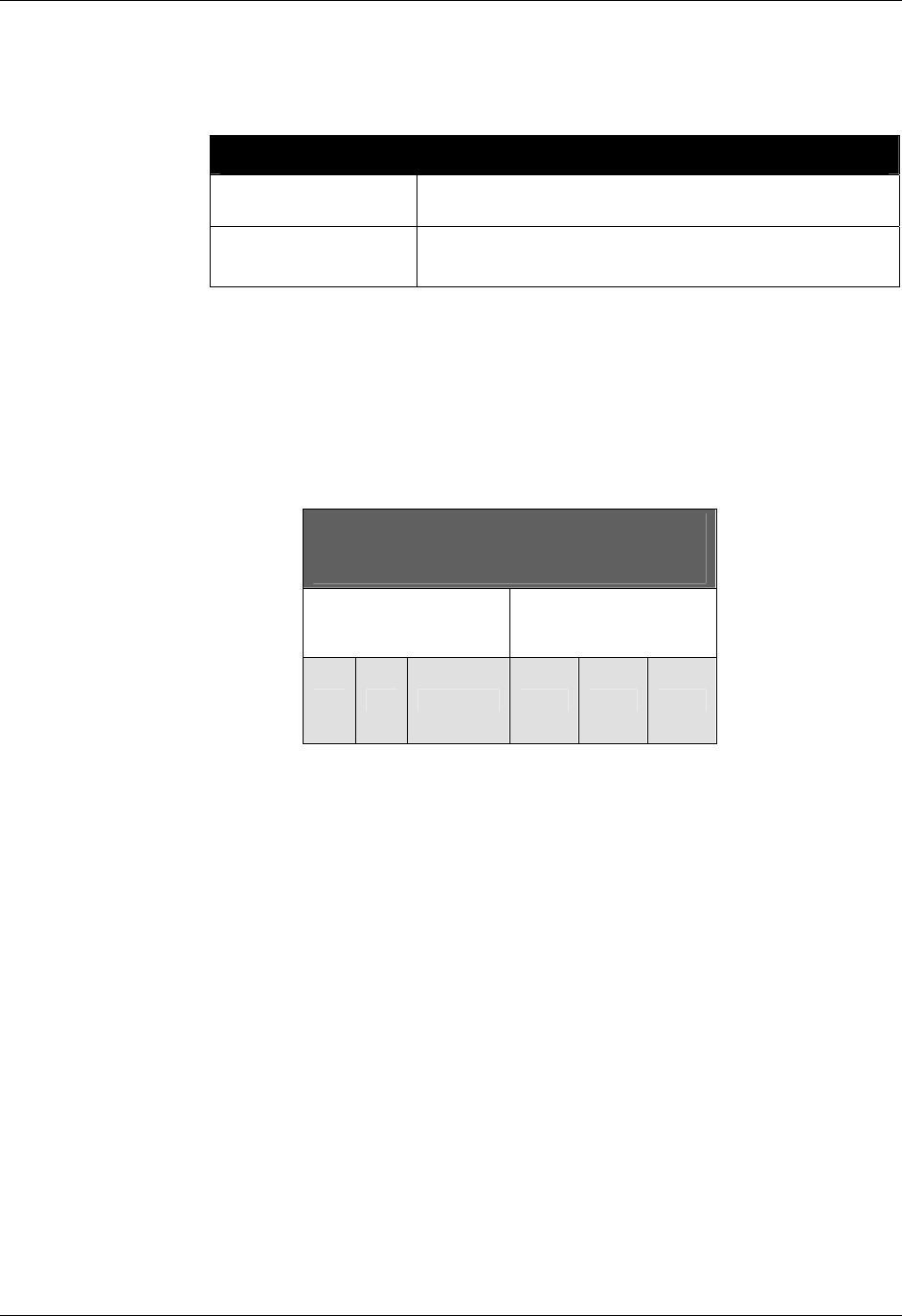
CHAPTER 4 ALIEN READER PROTOCOL
READER INTERFACE GUIDE
DOC. CONTROL # 8101938-000 REV 05
69
If an reader acquisition (which depends mainly on the AcquireCycles and
AcquireCount attributes) takes longer than the AutoStopTimer value, the
acquisition will complete before moving to the evaluate state.
AutoStopTimer Examples
Command
Response
>get AutoStopTimer
AutoStopTimer(ms) = 0
Command
Response
>set AutoStopTimer = 1000
AutoStopTimer (ms) = 1000
AUTOSTOPTIMER AND THE ALR-9770
In the ALR-9770, the AutoStopTimer plays a dual role – it also specifies the time
the reader spends performing a single read cycle, whether a single AutoMode
cycle, or an interactive "get TagList" command.
The ALR-9770 schedules its allowed tag-acquisition time by first equally dividing
the AutoStopTimer value among the specified tag protocols, and then dividing
among the antennas.
AutoStopTimer
(ms)
protocol1 protocol2
a1 a2 a3 a1 a2 a3
For all Class 1 tags, the antenna arbitration algorithm is optimized for maximizing
the read rate of the tags in the field. For Class 0 tags, each antenna is given
112ms of search time. Thus, time division for antennas within a protocol cannot
be specified. When specifying the AutoStopTimer for a search over multiple tag
protocols, it is important to keep in mind the worst case of the multiple protocols.
To calculate a minimum value for AutoStopTimer, determine which protocol will
take the longest to read its tag population, then multiply that value by the number
of protocols and number of antennas.
AutoStopTimermin = max( NumTagsClass1*TimePerTagClass1,
NumTagsClass0*TimePerTagClass0
) * #Protocols * #Antennas
Typical time to read a Class1 tag is 16ms
Typical time to read a Class0 tag is 1.4ms
What happens if the AutoStopTimer is too small? The reader may not search
using all protocols, and/or it may not have time to search all specified antennas.
For instance, it is desired to read a mixed population of 20 Class1 and 20 Class0
tags, on three antennas. If a small timeout is used (250ms), the reader schedules
its time as follows:

ALIEN READER PROTOCOL CHAPTER 4
READER INTERFACE GUIDE
DOC. CONTROL # 8101938-000 REV 05
70
AutoStopTimer
(250ms)
Class 1
(125ms)
Class 0
(224ms)
a1
a2
a3
a1
(112ms)
a2
(112 ms)
First, the reader recognizes that it has to use two tag protocols, so it divides the
allotted 250ms equally among them. It uses the first 125ms to find as many
Class1 tags as possible on the three antennas. Since Class0 uses a minimum of
112ms per antenna, it has just enough time to search the first antenna, and start
looking on the second antenna. The reader does not have time to search the
third antenna for Class0 tags. (Notice that it does extend the AutoStopTimer long
enough to finish the current acquisition).
Using the equation given previously, the minimum value to use for
AutoStopTimer should be:
AutoStopTimermin = max(20*16ms, 20*1.4ms) * 2 * 3
= max(320, 28) * 6
= 1920 ms
In this case, the reader schedules its time as follows:
AutoStopTimer
(1920ms)
Class1
(960ms)
Class0
(960ms)
a1
a2
a3
a1
320
ms
a2
320
ms
a3
320
ms
Now there is plenty of time to read all protocols on all antennas.
AutoTrueOutput
9800 | 9780 | 8780 | 9640 | 9774
The AutoTrueOutput specifies the output pin settings to effect if the evaluate
mode of Autonomous Mode evaluates to true. The parameter is a bitmap for the
four external output pins, where a "1" sets a pin to high, and a "0" sets a pin to
low. Output pin 1 is specified by bit 0 in the mask, output pin 2 is specified by bit
1 in the mask, etc.

CHAPTER 4 ALIEN READER PROTOCOL
READER INTERFACE GUIDE
DOC. CONTROL # 8101938-000 REV 05
71
AutoTrueOutput Examples
Command
Response
>get AutoTrueOutput
AutoTrueOutput = 0
Command
Response
>set AutoTrueOutput = 3 (sets pins 0 and 1 high)
AutoTrueOutput = 3
AutoTruePause
9800 | 9780 | 8780 | 9640 | 9774
The AutoTruePause specifies a millisecond pause to effect if the autonomous
evaluation mode evaluates to true. This pause will occur after the
AutoTrueOutput command has been processed.
AutoTruePause Examples
Command
Response
>get AutoTruePause
AutoTruePause(ms) = 0
Command
Response
>set AutoTruePause = 500
AutoTruePause = 500
AutoFalseOutput
9800 | 9780 | 8780 | 9640 | 9774
The AutoFalseOutput specifies the output pin settings to effect if the evaluate
mode of Autonomous Mode evaluates to false. The parameter is a bitmap for the
four external output pins, where a "1" sets a pin to high, and a "0" sets a pin to
low. Output pin 1 is specified by bit 0 in the mask, output pin 2 is specified by bit
1 in the mask, etc.
AutoFalseOutput Examples
Command
Response
>get AutoFalseOutput
AutoFalseOutput = 0
Command
Response
>set AutoFalseOutput = 3
AutoFalseOutput = 3
AutoFalsePause
9800 | 9780 | 8780 | 9640 | 9774
The AutoFalsePause specifies a millisecond pause to effect if the autonomous
evaluation mode evaluates to false. This pause will occur after the
AutoFalseOutput command has been processed.
AutoFalsePause Examples
Command
Response
>get AutoFalsePause
AutoFalsePause (ms) = 0
Command
Response
>set AutoFalsePause = 500
AutoFalsePause = 500

ALIEN READER PROTOCOL CHAPTER 4
READER INTERFACE GUIDE
DOC. CONTROL # 8101938-000 REV 05
72
AutoModeStatus
9800 | 9780 | 8780 | 9640 | 9774
The Get AutoModeStatus command will return an integer representing the
current state of the auto mode state machine.
Additionally the status may be followed by an asterisk character (*). If present it
indicates that a complete auto mode cycle has occurred since the last get
AutoModeStatus command was issued. Calling this method will always clear the
* flag.
The following table details the different states returned:
AutoModeStatus : States Returned
0 Auto Mode is OFF
10 Auto Mode is initializing
20 Auto Mode is listening for a start trigger
30 Auto Mode is starting its Action
40 Auto Mode is processing its Action
50 Auto Mode is listening for a Stop condition
60 Auto Mode is entering its evaluation stage
70 Auto Mode is in its true or false pause stage
80 Auto Mode is in notify stage
AutoModeStatus Examples
Command
Response
>get AutoModeStatus
AutoModeStatus = 0
Command
Response
> Get AutoModeStatus
AutoModeStatus = 30*
AutoModeReset
9800 | 9780 | 8780 | 9640 | 9774
The AutoModeReset command will reset all auto mode parameters to their
default values, including setting the auto mode to off.
AutoModeReset Examples
Command
Response
>AutoModeReset
All AutoMode settings have been reset !
AutoModeTriggerNow
9800 | 9780 | 8780 | 9640 | 9774
The AutoModeTriggerNow command will emulate an external IO trigger event to
effect auto mode. This command will only work if the RFID Reader is already in
auto mode and is waiting for a start trigger condition. At this point, issuing the
AutoModeTriggerNow command will be identical to a real external trigger event,
forcing the auto mode into its action cycle.

CHAPTER 4 ALIEN READER PROTOCOL
READER INTERFACE GUIDE
DOC. CONTROL # 8101938-000 REV 05
73
AutoModeTriggerNow Examples
Command
Response
>AutoModeTriggerNow
Auto Mode Triggering Now
Notify Mode Commands
The Notify Mode commands are used to set up automated event notification
either on the expiration of a timer, or triggered off of events that occur with the
reader is running in Autonomous Mode.
NotifyMode
9800 | 9780 | 8780 | 9640 | 9774
The NotifyMode command turns on or off the notify mode.
Valid command parameters are ON and OFF.
The default setting is OFF.
NotifyMode Examples
Command
Response
>get NotifyMode
NotifyMode = ON
Command
Response
>set NotifyMode = on
NotifyMode = ON
NotifyAddress
9800 | 9780 | 8780 | 9640 | 9774
The Notify Address command pair specifies where notification messages should
be sent when they occur and how they should be sent. The form of the address
determines the method of delivery.
Currently there are 3 delivery methods supported as shown in the table below:
NotifyAddress Description
user@domain.com
Send a message via e-mail to the address specified. The
address is specified in standard email form, i.e.,
user@domain.com
NOTE: the MailServer parameter must be configured for this
to work. Optionally the MailFrom parameter can be used.
hostname:port Send a message to a specified port on a networked
machine. The address takes the form “hostname:port.” For
example, “123.01.02.98:3450” or
“listener.alientechnology.com:10002”
serial Send a message to the serial connection. The word “serial”
is used as the address. The word is not case sensitive.

ALIEN READER PROTOCOL CHAPTER 4
READER INTERFACE GUIDE
DOC. CONTROL # 8101938-000 REV 05
74
NotifyAddress Examples
Command
Response
>get NotifyAddress
NotifyAddress = 10.1.0.12:4000
Command
Response
>set NotifyAddress = user@msn.com
NotifyAddress = user@msn.com
NotifyTime
9800 | 9780 | 8780 | 9640 | 9774
The Notify Time commands assign and retrieve the time interval for automatic
TagList pushing to a listening machine.
The time is specified in seconds.
If set to zero, the time-based automatic notification is disabled.
When set to a positive number of seconds, a standard notification
message will be sent out each period.
NotifyTime Examples
Command
Response
>get NotifyTime
NotifyTime = 30
Command
Response
>set NotifyTime = 30
NotifyTime = 30
NotifyTrigger
9800 | 9780 | 8780 | 9640 | 9774
The NotifyTrigger command specifies and retrieves the event conditions (other
than time-based) upon which a notification message is sent out. Notify messages
can be triggered under any of the following conditions:
Trigger Name Meaning
Add Send message when new tag is read and added to the
TagList.
Remove Send message when a tag is removed from the TagList.
Change Send message when a tag is either added to or removed
from the TagList.
True Send message when the evaluation task of the autonomous
state loop evaluates to true, typically when tags are added
to the taglist.
False Send message when the evaluation task of the autonomous
state loop evaluates to false, typically when tags are not
added to the taglist.
TrueFalse Send message when the evaluation task of the autonomous
state loop evaluates to true or false (i.e. every time).

CHAPTER 4 ALIEN READER PROTOCOL
READER INTERFACE GUIDE
DOC. CONTROL # 8101938-000 REV 05
75
NotifyTrigger Examples
Command
Response
>get NotifyTrigger
NotifyTrigger = Remove
Command
Response
>set NotifyTrigger = add
NotifyTrigger = Add
NotifyFormat
9800 | 9780 | 8780 | 9640 | 9774
The NotifyFormat parameter specifies the format of any notification message.
The format may be one of the following:
NotifyFormat Description
Text
TagLists are sent out as plain text messages, one tag ID per
line.
Terse Similar to the Text format, except TagList data is formatted
in the terse format.
XML TagLists are sent out in XML text format.
Custom Similar to the Text format, except TagList data is formatted
as defined by the TagListCustomFormat command.
Text-formatted TagLists take the form:
#Alien RFID Reader Auto Notification Message
#ReaderName: Spinner Reader
#ReaderType: Alien RFID Tag Reader (Class 1 / 915Mhz)
#IPAddress: 10.1.70.13
#CommandPort: 23
#Time: 2003/01/21 12:48:59
#Reason: TEST MESSAGE
Tag:8000 8004 0000 003B, Disc:2003/12/04 15:08:59,
Last:2003/12/04 15:08:59, Count:4, Ant:0
Tag:8000 8004 9999 0004, Disc:2003/12/04 15:08:59,
Last:2003/12/04 15:08:59, Count:3, Ant:0
#End of Notification Message
Terse-formatted TagLists take the form:
#Alien RFID Reader Auto Notification Message
#ReaderName: Spinner Reader
#ReaderType: Alien RFID Tag Reader (Class 1 / 915Mhz)
#IPAddress: 10.1.70.13
#CommandPort: 23
#Time: 2003/01/21 12:48:59
#Reason: TEST MESSAGE
8000 8004 0000 003B,4,0
8000 8004 9999 0004,3,0
#End of Notification Message
XML-formatted TagLists take the form:

ALIEN READER PROTOCOL CHAPTER 4
READER INTERFACE GUIDE
DOC. CONTROL # 8101938-000 REV 05
76
<Alien-RFID-Reader-Auto-Notification>
<ReaderName>Spinner Reader</ReaderName>
<ReaderType>
Alien RFID Tag Reader (Class 1 / 915Mhz)
</ReaderType>
<IPAddress>10.1.70.13</IPAddress>
<CommandPort>23</CommandPort>
<Time>2003/01/21 12:49:22</Time>
<Reason>TEST MESSAGE</Reason>
<Alien-RFID-Tag-List>
<Alien-RFID-Tag>
<TagID>8000 8004 0000 003B </TagID>
<DiscoveryTime>2003/12/04 15:08:59</DiscoveryTime>
<LastSeenTime>2003/12/04 15:08:59</LastSeenTime>
<Antenna>0</Antenna>
<ReadCount>4</ReadCount>
</Alien-RFID-Tag>
<Alien-RFID-Tag>
<TagID>8000 8004 9999 0004</TagID>
<DiscoveryTime>2003/12/04 15:08:59</DiscoveryTime>
<LastSeenTime>2003/12/04 15:08:59</LastSeenTime>
<Antenna>0</Antenna>
<ReadCount>3</ReadCount>
</Alien-RFID-Tag>
</Alien-RFID-Tag-List>
</Alien-RFID-Reader-Auto-Notification>
NotifyHeader
9800 | 9780 | 8780 | 9640 | 9774
The NotifyHeader command turns on or off the header portion of each notification
message. When the NotifyHeader is turned off, notification messages contain
only the TagList portion of the message.
Valid command parameters are ON and OFF.
The default setting is ON.
NotifyMode Examples
Command
Response
>get NotifyHeader
NotifyHeader = On
Command
Response
>set NotifyHeader = off
NotifyHeader = Off
NotifyKeepAliveTime
9800 | 9780 | 8780 | 9640 | 9774
When the reader sends a notification message out over the network, it needs an
open TCP socket to do so. Opening and closing a socket entails some processor
and network overhead, and if the notifications are coming out of the reader
rapidly, this overhead can become a burden that hinders reader responsiveness.
The NotifyKeepAliveTime attribute sets the amount of time (in seconds) that the
reader will keep this socket open. For rapid notifications, it may be advantageous
for the reader to hold the socket open continuously. You do this by setting
NotifyKeepAliveTime to some value greater than the expected time between
notifications.
CHAPTER 4 ALIEN READER PROTOCOL
READER INTERFACE GUIDE
DOC. CONTROL # 8101938-000 REV 05
77
On the other hand, holding the socket open places a burden on the network. For
infrequent notifications, it is advantageous to leave the NotifyKeepAliveTime
small so that the socket is opened only long enough for a single notification to be
sent out, and is then closed automatically after message delivery.
The time can range from 0 to 65535 seconds.
The default value is 30 seconds.
NotifyKeepAliveTime Examples
Command
Response
>get NotifyKeepAliveTime
NotifyKeepAliveTime (secs) = 30
Command
Response
>set NotifyKeepAliveTime = 90
NotifyKeepAliveTime (secs) = 90
MailServer
9800 | 9780 | 8780 | 9640 | 9774
The MailServer command pair allow you to define an SMTP (simple mail transfer
protocol) mail server. This mail server is used only when automatic notification is
configured (see Notify commands) and is set to use Mail as its delivery method.
MailServer Examples
Command
Response
>get MailServer
MailServer = 12.34.56.78
Command
Response
>set MailServer = 45.224.124.34
MailServer = 45.224.124.34
MailFrom
9800 | 9780 | 8780 | 9640 | 9774
The MailFrom command pair allows you to define the email address associated
with the RFID Reader. The emails sent out by the RFID Reader will have this
parameter set in the From: field of the email header.
MailFrom Examples
Command
Response
>get MailFrom
MailFrom = AlienRFIDReader
Command
Response
>set MailFrom = reader@mycompany.com
MailFrom = reader@mycompany.com
NotifyRetryCount
9800 | 9780 | 8780 | 9640 | 9774
If a network notification fails to connect to a host at the specified NotifyAddress,
the reader will attempt to resend the notification message. Rather than endlessly
retrying a failed operation (which needlessly consumes reader resources), the
reader will stop after the number of attempts reaches the NotifyRetryCount. At
this point the reader turns NotifyMode off.

ALIEN READER PROTOCOL CHAPTER 4
READER INTERFACE GUIDE
DOC. CONTROL # 8101938-000 REV 05
78
The value can range from 0 to 32767.
The default value is 3 retries.
The period between retries is given by the NotifyRetryPause (below).
NotifyRetryCount Examples
Command
Response
>get NotifyRetryCount
NotifyRetryCount = 3
Command
Response
>set NotifyRetryCount = 0
NotifyRetryCount = 0
NotifyRetryPause
9800 | 9780 | 8780 | 9640 | 9774
When the reader attempts to send a network notification and fails, it tries again a
number of times specified by NotifyRetryCount. The time period between these
retries is specified by the NotifyRetryPause.
The value can range from 0 to 32767 seconds.
The default value is 10 seconds.
NotifyRetryPause Examples
Command
Response
>get NotifyRetryPause
NotifyRetryPause (secs) = 10
Command
Response
>set NotifyRetryPause = 60
NotifyRetryPause (secs) = 60
NotifyNow
9800 | 9780 | 8780 | 9640 | 9774
The NotifyNow command instructs the reader to send out an immediate
notification of its TagList to the address currently set by the NotifyAddress
command.
NotifyNow Examples
Command
Response
>NotifyNow
Issuing Notify Trigger...

CHAPTER 5 TAG PROGRAMMING
READER INTERFACE GUIDE
DOC. CONTROL # 8101938-000 REV 05
79
CHAPTER 5
Tag Programming
All Alien RFID tags support programmable ID numbers. This chapter describes
the series of commands required to program EPC-compliant ID codes and user-
defined ID codes into Alien RFID tags, and details some of the physical
conditions required to carry out successful programming tasks.
Enabling The Programmer
By default all Alien RFID Readers are shipped with tag-programming commands
disabled. Before being able to program tags, these programming commands
must be enabled. You do this by issuing the following command to the Reader
via a command-line terminal:
Alien >set Function = Programmer
Function = Programmer
To disable these commands again, issue the following command:
Alien >set Function = Reader
Function = Reader
Once the functions have been enabled, issuing a "Help" command will reveal a
new suite of commands under the title "Programming" (not all of the commands
shown are available with all readers):
>Help
.
.
.
PROGRAMMING:
Get|Set ProgAntenna
Set Program Tag
Verify Tag
Erase Tag
Set Lock Tag
Set Kill Tag
Get|Set ProgramID (for automatic programming)
Get|Set ProgramPassCode (for automatic programming)
Get|Set ProgReadAttempts
Get|Set ProgEraseAttempts
Get|Set ProgIncrementOnFail
Get|Set ProgAttempts
Tag Memory Structure
Knowing the tag memory structure is essential for successfully programming tags
and using mask commands to acquire subsets of tags. This chapter describes
the basic memory formats supported by all Alien tag systems.
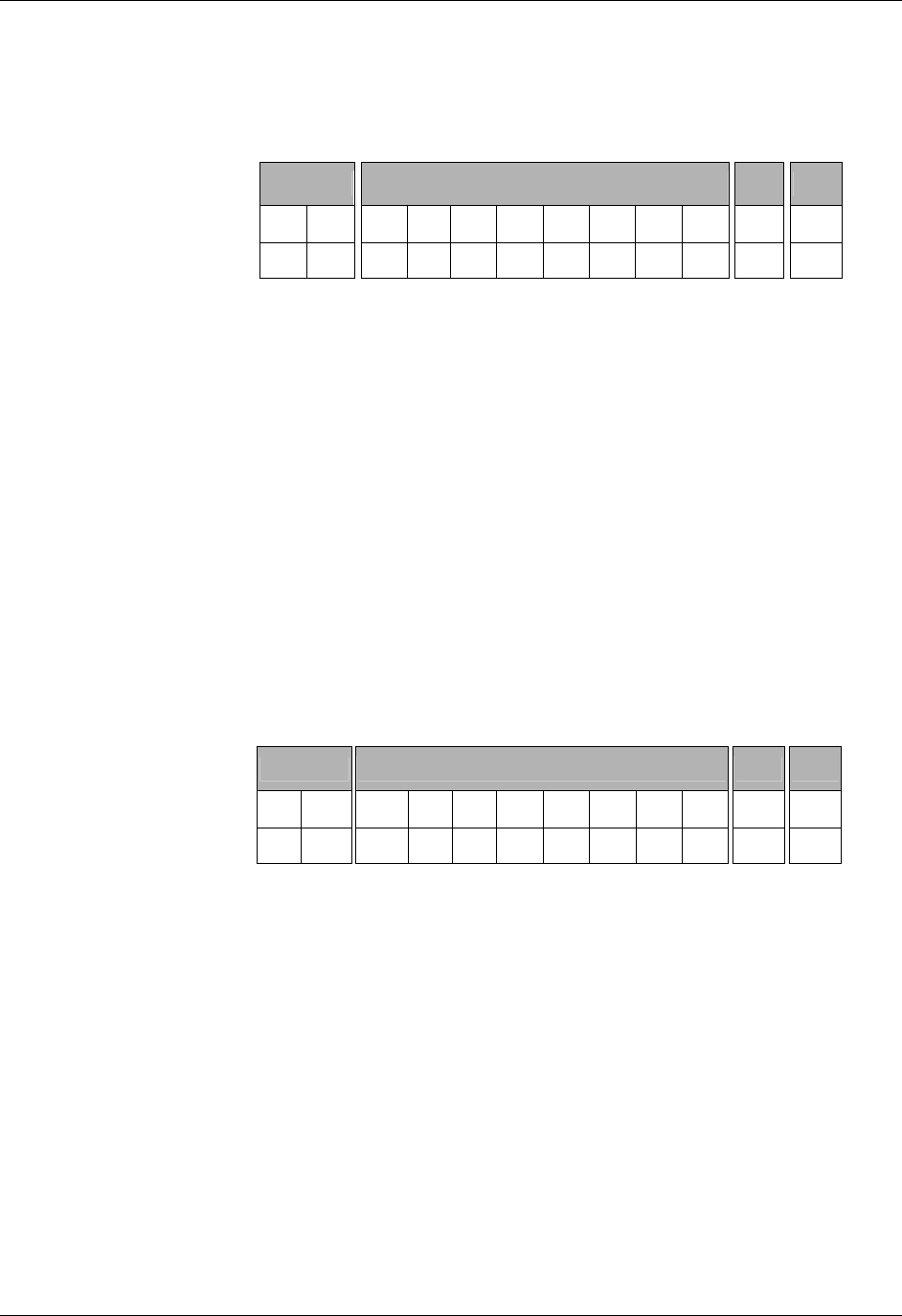
TAG PROGRAMMING CHAPTER 5
READER INTERFACE GUIDE
DOC. CONTROL # 8101938-000 REV 05
80
Class I Tags (96-bit)
"Quark" and "Omega" Class I tags from Alien contain 96 bits of programmable
memory, of which 64 bits are user-programmable. The remaining 32 bits are
controlled by the reader to record state and checksum information inside the tag.
Checksum EPC Code (or User ID Code) Lock PC
B
yte 0 1 0 1 2 3 4 5 6 7 0 0
B
it 0-7 8-15 0-7 8-15 16-23 24-31 32-39 40-47 48-55 56-63 0-7 0-7
Class I 96-bit Tag Memory Structure
The ID Code memory is address from left to right, where the leftmost bit (the
Most Significant Bit) is bit 0, and the rightmost bit (the Least Significant Bit) is bit
63. There is no restriction on the data that resides in this portion of the tag.
The Checksum is calculated over the 64 bits of the ID Code only. The checksum
is calculated and programmed into the tag automatically by the reader. This
checksum is calculated using the CCITT-16 standard.
The Lock and PassCode (PC) bytes stored at the end of tag memory are used to
lock a tag and kill a locked tag. Each of these codes takes exactly one byte. The
user can control the value of the PassCode, passing it in as a parameter to the
Lock command. The reader takes full control of the Lock byte, allowing it to flag
the tag as either locked or unlocked.
Class I Tags (128-bit)
"Lepton" Class I tags from Alien contain 128 bits of programmable memory, of
which 96 bits are user-programmable. The remaining 32 bits are controlled by
the reader to record state and checksum information inside the tag.
Checksum EPC Code (or User ID Code) Lock PC
B
yte 0 1 0 1 2 3 … 9 10 11 0 0
B
it 0-7 8-15 0-7 8-15 16-23 24-31 … 72-79 80-87 88-95 0-7 0-7
Class I 128-bit Tag Memory Structure
The ID Code memory is address from left to right, where the leftmost bit (the
Most Significant Bit) is bit 0, and the rightmost bit (the Least Significant Bit) is bit
95. There is no restriction on the data that resides in this portion of the tag.
The Checksum is calculated over the 96 bits of the ID Code only. The checksum
is calculated and programmed into the tag automatically by the reader. This
checksum is calculated using the CCITT-16 standard.
The Lock and PassCode (PC) bytes stored at the end of tag memory are used to
lock a tag and kill a locked tag. Each of these codes takes exactly one byte. The
user can control the value of the PassCode, passing it in as a parameter to the
Lock command. The reader takes full control of the Lock byte, allowing it to flag
the tag as either locked or unlocked.

CHAPTER 5 TAG PROGRAMMING
READER INTERFACE GUIDE
DOC. CONTROL # 8101938-000 REV 05
81
Class BPT Tags
Class BPT tags from Alien support 96 bits of programmable ID memory. Unlike
the Class I tag, all 96 bits are user-addressable and user-programmable. There
are no prerequisites for the content of this memory space.
EPC Code (or User ID Code)
B
yte 0 1 2 3 4 5 6 7 8 9 10 11
B
it 0-7 8-15 16-23 24-31 32-39 40-47 48-55 56-63 64-71 72-79 80-87 88-95
Class BPT Tag Memory Structure
The Class BPT tag does not support Lock or Kill.
Programming Distance & Power Levels
Caution: It is highly recommended that you read and understand this
section before programming tags.
The term “programming” as used in this manual refers to the operations that alter
the tag memory. These include the Erase Tag, Program Tag, Lock Tag and Kill
Tag commands. These commands are discussed in some detail later in this
chapter. From the operational and software point of view, programming tag IDs is
very simple, in most cases requiring just the click of a button or the issuance of
one command. However, several variables affect programming reliability and
must be properly addressed in every application. There are three factors under
your control to assure programming success in any application: application
software, attenuation, and the physical position of the tags.
Programming Power
Programming a tag requires substantially more power than reading a tag. As a
result, the tag's programming range will be substantially less than its read range.
Programming commands will affect all tags that receive sufficient power to
execute the commands. As a result, the tag to be programmed should be
physically isolated from tags that you do not intend to program. Similarly, you
should program at the minimum power that will reliably program the tag in the
given environment, so as not to affect nearby tags. A lower programming power
requires a shorter physical separation of tags.
The power received by the tag is determined by the power supplied to the
antenna, the distance tag is from the antenna, and the level of signal reflections
from the environment and the object being tagged. Environmental reflections can
cause local power nulls near the tag, and it will not be programmed due to
insufficient power. Tag separation from the antenna should be as constant as
possible, to minimize power variation and to avoid special nulls due to reflection.
Tag orientation with respect to the antenna should also be controlled. In
particular, when using a linear antenna the tag should be presented in the same
orientation as the antenna polarization. The power supplied to the antenna is
controlled by the use of attenuators to reduce the signal strength. The attenuator
value is selected based on careful measurements in the environment after other
variables have been controlled as described above. A variable attenuator is a
useful tool in setting the final attenuation values.

TAG PROGRAMMING CHAPTER 5
READER INTERFACE GUIDE
DOC. CONTROL # 8101938-000 REV 05
82
Programming Range
Alien tags can be programmed over a substantial range. In a free space
environment with no attenuation and a linear antenna the tag should be set no
closer than 50 cm (20 in) from the antenna when attempting to program. The tag
may be placed closer to the antenna but programming reliability may suffer. If
programming is attempted very close to the antenna, the tag may be
permanently damaged and rendered un-programmable. Again, your physical
environment will affect programming results due to power nulls created by
reflections from the floor, walls, metal structures, etc. When using a circular
antenna in a free space environment with no attenuator, the tag should be set no
closer than 50 cm from the antenna when attempting to program.
Programming Problems
The most common result of poor programming is that the tag will no longer read
in Global Scroll or Inventory modes. This is due to the tag memory being erased
or incompletely programmed. Tags in this state can be read using the Verify Tag
command and can be programmed using the Program Tag commands.
Typically, tag erasure without programming success (the Verify Tag command
will return all 0’s) is caused by insufficient power since the erase process
requires less energy than the programming process. Power should be increased
by either decreasing attenuation or moving the tag closer to the antenna and
repeating the programming process.
Incompletely programmed tags can be caused by insufficient or excessive
programming power. Revaluate the tag position and the signal attenuation and
repeat the programming sequence.
A step attenuator is a powerful tool in evaluating programming conditions. When
using the attenuator, set it to the highest value at which you can reliably read the
tag. You can then step down approximately 10 dB from this value as an estimate
of the proper attenuation for programming. By varying the attenuator value you
can optimize programming conditions over the range of the other variables in
your application.
Programming Slept Tags
A common programming mistake is attempting to program a slept tag. A tag may
be left in a sleep state after reading it, and subsequent attempts to program it
may fail. This can be remedied by issuing an explicit "Wake" command before
programming, or by carefully setting the Acquire parameters, AcqSleepCount
and AcqExitWakeCount.
When AcqSleepCount is not zero, the reader puts tags to sleep as it reads them,
making it easier to find other tags in the field. The AcqExitWakeCount property
allows you to specify a number of Wake commands to be issued after each read
cycle – waking up the entire tag population that was read in that cycle. If
AcqExitWakeCount is zero, these Wake commands aren't issued at all, and tags
may be left in a slept state.
By either setting AcqSleepCount to zero, or making sure AcqExitWakeCount is
not zero, you can ensure that tags are not left sleeping.

CHAPTER 5 TAG PROGRAMMING
READER INTERFACE GUIDE
DOC. CONTROL # 8101938-000 REV 05
83
Programming Commands Summary
Command Description
9800
9780
8780
9640
9770
Program Tag Programs a tag with a specified ID. ✔✔✔✔✔
Erase Tag Erases a tag. ✔✔✔✔✔
get ProgAntenna
set ProgAntenna
Gets and Sets the antenna on which to issue
programming commands. ✔✔✔✔✔
get ProgReadAttempts
set ProgReadAttempts
Gets and Sets the number of attempts to verify a tag
before programming it. ✔✔✔✔
get ProgEraseAttempts
set ProgEraseAttempts
Gets and Sets the number of attempts to erase a tag
before programming it. ✔✔✔✔
get ProgAttempts
set ProgAttempts
Gets and Sets the number of attempts to program a
tag. ✔✔✔✔
Lock Tag Locks a tag with a specified PassCode. ✔✔✔✔ ✔
Kill Tag Kills a locked tag with a specified PassCode. ✔✔✔✔ ✔
Verify Tag Asks a tag to return its entire tag data. ✔✔✔✔
get ProgramID
set ProgramID
Gets and Sets the next ID used to program tags while
in Autonomous Mode (increments upon success). ✔✔✔✔
get ProgramPassCode
set ProgramPassCode
Gets and Sets the PassCode used to lock tags while in
Autonomous Mode. ✔✔✔✔
get ProgIncrementOnFail
set ProgIncrementOnFail
Gets and Sets the flag that specifies if the ProgramID
should increment when a program operation fails. ✔✔✔✔
Program and Erase Functions
The two most common methods of altering tag memory are the Program Tag and
Erase Tag commands. These two functions are supported by all Alien RFID tags,
including Class I and Class BPT systems.
The Program Tag function programs a user-defined ID into the tag memory. The
Erase function erases all data in the tag memory, setting all the tag data bytes to
zero.
Program Tag
9800 | 9780 | 8780 | 9640 | 9774
The Program Tag command allows the user to specify the ID to program into a
tag. Once the command is issued, the reader verifies the presence of a tag,
erases it, programs it, then reads back the tag memory to verify that the program
command worked properly.
Tags that are locked cannot be Programmed.
The Program Tag command expects you to supply a list of hexadecimal
bytes separated by spaces, representing the tag memory to program.

TAG PROGRAMMING CHAPTER 5
READER INTERFACE GUIDE
DOC. CONTROL # 8101938-000 REV 05
84
Program Tag Examples
Condition Exactly one tag in field of view. Tag read is strong.
Program a Class I tag with a new 64-bit ID.
Command
Response
>program tag = 80 00 FF EE 10 00 00 01
Program Tag = 80 00 FF EE 10 00 00 01
Condition Tag on fringe of read range.
Command
Response
>program tag = 80 00 FF EE 10 00 00 01
Program Tag = Error : No Tag Found.
Condition Tag is Locked
Command
Response
>program tag = 80 00 00 00 10 00 00 01
Program Tag = Error : Tag Is Locked. Cannot Program.
CLASS I TAGS
Programming a Class I tag requires 8 or 12 bytes of ID code (depending on tag
type). The reader automatically calculates the checksum for this ID and programs
that in addition to the ID code. The lock and PassCode bytes are set to zero.
CLASS BPT TAGS
Programming a Class BPT tag requires 12 bytes of ID code. The Class BPT
does not require a checksum code, and does not support lock and kill. Therefore
the entire 12 bytes of tag memory are addressable with this command.
Erase Tag
9800 | 9780 | 8780 | 9640 | 9774
The Erase Tag command attempts to erase the memory of a tag in the reader’s
field of view. A tag affected by this command has its entire tag memory set to
zero. Once the command is issued, the reader verifies the presence of a tag,
erases it, then reads back the tag memory to verify that the erase command
worked properly.
The reader erases all tags in the field of the ProgAntenna.
Tags that are locked or not programmed cannot be Erased.
Erase Tag Examples
Condition Exactly one tag in field of view. Tag read is strong.
Erase command will erase memory, setting to all zeros.
Command
Response
>erase tag
Erase Tag = Success!
Condition One or more tags on fringe of read range.
Command
Response
>erase tag
Erase Tag = Error : No Tag Found.
Condition Tag is Locked
Command
Response
>erase tag
Erase Tag = Error : Tag Is Locked. Cannot Erase.

CHAPTER 5 TAG PROGRAMMING
READER INTERFACE GUIDE
DOC. CONTROL # 8101938-000 REV 05
85
ProgAntenna
9800 | 9780 | 8780 | 9640 | 9774
Programming tags requires a controlled, repeatable RF environment (see
previous section titled, "Programming Distance and Power Levels"), and in most
cases, programming commands can potentially effect all the tags in the RF field.
For this reason, rather than using the AntennaSequence to indicate which
antenna(s) to issue programming commands on, you use the ProgAntenna
attribute instead.
All programming commands are issued on the antenna port specified by
ProgAntenna, regardless of the current AntennaSequence value.
ProgAntenna Examples
Command
Response
>get ProgAntenna
ProgAntenna = 0
Command
Response
>set ProgAntenna = 2
ProgAntenna = 2
ProgReadAttempts
9800 | 9780 | 8780 | 9640 | 9774
When the reader is asked to perform a programming operation, often the first
step is to verify the presence of a tag in the field. If there is not identifiable tag in
the field, the reader won't bother continuing with the rest of the operation. The
ProgReadAttempts attribute specifies the number of attempts the reader should
make to verify the presence of a tag.
The value can range from 1 to 255.
The default value is 10.
ProgReadAttempts is used in the following programming commands:
Program Tag
Erase Tag
Kill Tag
Lock Tag
ProgReadAttempts Examples
Command
Response
>get ProgReadAttempts
ProgReadAttempts = 10
Command
Response
>set ProgReadAttempts = 5
ProgReadAttempts = 5
ProgEraseAttempts
9800 | 9780 | 8780 | 9640 | 9774
The ProgEraseAttempts attribute specifies the number of attempts the reader
should make to erase a tag. This value is used as a parameter in an Erase Tag

TAG PROGRAMMING CHAPTER 5
READER INTERFACE GUIDE
DOC. CONTROL # 8101938-000 REV 05
86
operation, but is also used in a Program Tag operation, since a tag is erased
before it is programmed.
The value can range from 1 to 255.
The default value is 10.
ProgEraseAttempts is used in the following programming commands:
Program Tag
Erase Tag
ProgEraseAttempts Examples
Command
Response
>get ProgEraseAttempts
ProgEraseAttempts = 10
Command
Response
>set ProgEraseAttempts = 5
ProgEraseAttempts = 5
ProgAttempts
9800 | 9780 | 8780 | 9640 | 9774
The ProgAttempts attribute specifies the number of attempts the reader should
make to program a tag during a Program Tag operation.
The value can range from 1 to 255.
The default value is 3.
ProgAttempts Examples
Command
Response
>get ProgAttempts
ProgAttempts = 3
Command
Response
>set ProgAttempts = 5
ProgAttempts = 5
Lock and Kill Functions (Class I Only)
The Class I tags support two additional commands, not yet supported by the
Class BPT tags. These two functions, called Lock and Kill, provide a rudimentary
locking scheme to prevent tag memory being overwritten accidentally or on
purpose.
Lock Tag
9800 | 9780 | 8780 | 9640 | 9774
A tag can be locked to prevent its memory from being changed. Once locked
there is only one way to change the memory, and that is to Kill the tag.
There is no "unlock" command.

CHAPTER 5 TAG PROGRAMMING
READER INTERFACE GUIDE
DOC. CONTROL # 8101938-000 REV 05
87
The Lock Tag command takes one argument: the PassCode, which is a
hexadecimal byte in the range 00-FF. If the PassCode is not supplied, the
reader uses 00 be default. This PassCode is required by the Kill command, as
described below.
Lock Tag Examples
Condition Exactly one tag in field of view. Tag read is strong.
Lock tag with pass code of 5F.
Command
Response
>lock tag = 5F
Lock Tag = Success!
Condition Tag on fringe of read range, or no valid tags in range
Command
Response
>lock tag = 5F
Lock Tag = Error : No Tag Found.
Condition Tag is already Locked
Command
Response
>lock tag = 5F
Lock Tag = Error : Tag Is Locked.
Kill Tag
9800 | 9780 | 8780 | 9640 | 9774
The Kill Tag command is used to recover a locked tag, allowing it to be
programmed again. A locked tag cannot be erased or reprogrammed; the only
programming operation that can be performed on a locked tag is the Kill Tag
operation.
Kill Tag sets all bytes of tag memory to zero.
Kill Tag can only be used on locked tags.
There is no "unlock" command.
To use the Kill Tag command, the full tag ID of the tag to kill must be provided as
well as the PassCode that was used to lock the tag with. These parameters are
passed as 9 or 13 (depending on tag type) consecutive hexadecimal numbers
separated by spaces.
Kill Examples
Condition Exactly one tag in field of view. Tag read is strong.
Tag ID is 80 00 01 00 02 00 03 00. Locked using pass code 5F.
Kill Tag command is successful.
Command
Response
>kill tag = 80 00 01 00 02 00 03 00 5F
Kill Tag = Success!
Condition Exactly one tag in field of view. Tag read is strong.
Tag ID is 80 00 01 00 02 00 03 00. Locked using pass code 5F.
Kill Tag command fails because PassCode is wrong.
Command
Response
>kill tag = 80 00 01 00 02 00 03 00 1A
Kill Tag = Error : Kill Failure.
Once a tag is killed, its memory contents (including CRC bytes) are cleared to all
zeros, making the tag unreadable. It may then be reprogrammed with a new ID.

READERHOST PROTOCOL CHAPTER 4
READER INTERFACE GUIDE
DOC. CONTROL # 8101938-000 REV 05
88
Acquire vs. Verify
There are two different methods with which to read tags in the field, the Acquire
mode and the Verify mode. Up to now, when this document referred to "reading
tags", it meant "Acquire". When programming is taken into consideration, a
second mode, called "Verify", should be considered.
The reader acquires tags when the "get TagList" command is issued to the
reader, or the reader is reading tags in Autonomous Mode. The actual method
used to acuire the tags in the reader's field is determined by the AcquireMode
setting. This is typically "Inventory" or "Global Scroll". See chapter 3, "Tag
Fundamentals", for more details on the differences between these methods.
Regardless of the actual command issued to read a tag in Acquire mode, the tag
ID returned is always a fully formed ID code, checked against the checksum for
any errors.
This error checking is done by reading the tag ID and calculating its checksum,
then comparing it to the checksum contained within tag memory. If they are
equal, the tag ID is presented to the user. However if a discrepancy occurs
between the checksum and the ID, for example due to a poor air interface
between the tag and reader, then the tag ID is rejected.
Any tag IDs presented to the user by the Acquire commands are therefore
always checked for accuracy.
Note: A tag that is not programmed correctly will not be validated by the
Acquire commands and will be rejected when read.
Note: A tag that has been erased will contain neither a tag ID nor a
checksum. These tags will also be rejected by Acquire commands.
The Verify command is used specifically for interrogating the state of a tag that
may or may not be readable by the Acquire commands.
Verify Tag
9800 | 9780 | 8780 | 9640 | 9774
A Verify Tag command returns the complete tag memory without validating the
tag ID against the checksum. The tag memory returned by the Verify Tag
command is not guaranteed to be correct; it may or may not be valid.
For the Class I tags, the Verify Tag command returns 12 or 16 bytes of memory:
2 bytes of checksum data, followed by 8 or 12 bytes of tag ID (depending on tag
type), followed by Lock and PassCode bytes. Verify is unable to return a value
for a locked tag. (This is to prevent the tag from revealing its PassCode while
locked).
The Verify command returns an error message if the tag is locked.
For the Class BPT tags, the Verify command returns the entire 12 bytes
of tag ID.
A Verify command cannot sort multiple tags; it should only be used on
one tag at a time.

CHAPTER 4 READERHOST PROTOCOL
READER INTERFACE GUIDE
DOC. CONTROL # 8101938-000 REV 05
89
There are a number of responses to the Verify Tag command, depending on the
state of the tag field at the time the command is issued. Examples follow:
Verify Tag Examples
Condition Exactly one tag in field of view. Tag read is strong.
Verify command returns checksum bytes followed by tag ID
bytes, followed by lock and PassCode bytes. (Acquire
commands return just the tag ID of this tag).
Command
Response
>verify tag
Verify Tag = 235C 8000 0000 1001 0102 0000
Condition Exactly one tag in field of view. Tag is erased and has no tag ID
or checksum programmed into it. (Acquire commands reject this
tag).
Command
Response
>verify tag
Verify Tag = 0000 0000 0000 0000 0000 0000
Condition No tags in field of view, or multiple tags in field of view.
Command
Response
>verify tag
Verify Tag = No Tag Detected.
Condition Exactly one tag in field of view. Tag read is strong. But tag is
locked. Locked tags are prevented from being read by a Verify
command. (Acquire commands return tag ID of this tag).
Command
Response
>verify tag
Verify Tag = Programmed Tag. (Locked)
Condition A tag is on the fringe of the field, there is excessive noise, or the
tag is improperly programmed.
Command
Response
>verify tag
Verify Tag = Tag-Like Signal Detected.
Programming Tags in AutoMode
Programming functions are fully supported by the reader's Autonomous Mode of
operation. Using Autonomous Mode, the user can assign the reader the task of
programming, erasing, and locking tags. This is done by setting the AutoAction
attribute to the appropriate action, as described below.
Two of the AutoMode functions, "Program" and "Program and Lock" require
some additional values to be specified first, specifically the ProgramID and
ProgramPassCode.
ProgramID
9800 | 9780 | 8780 | 9640 | 9774
The ProgramID attribute is used in AutoMode when a program operation has
been selected as the AutoAction, such as "Program" or "Program and Lock". This
command allows the user to specify the first ID code to program into a tag. Once
a tag has been successfully programmed, the ID is incremented by one, ready
for the next tag to be programmed.
Value supplied must be an 8- or 12-byte tag ID.
The default ProgramID is 00 00 00 00 00 00 00 00.

READERHOST PROTOCOL CHAPTER 4
READER INTERFACE GUIDE
DOC. CONTROL # 8101938-000 REV 05
90
Value is automatically incremented (in a hexadecimal fashion) upon a
completion of a successful programming operation.
ProgramID Examples
Command
Response
>set ProgramID = 01 23 45 67 89 AB CD EF
ProgramID = 01 23 45 67 89 AB CD EF
Command
Response
>get ProgramID
ProgramID = 01 23 45 67 89 AB CD EF
ProgramPassCode
9800 | 9780 | 8780 | 9640 | 9774
The ProgramPassCode attribute is used in AutoMode when the AutoAction has
been set to "Program and Lock". The reader will use the value of
ProgramPassCode as the PassCode used to lock the ID after successfully
programming it.
Value supplied must be a single byte.
The default ProgramPassCode is 0x01.
ProgramPassCode Examples
Command
Response
>get ProgramPassCode
ProgramPassCode = 01
Command
Response
>set ProgramPassCode = FF
ProgramPassCode = FF
ProgIncrementOnFail
9800 | 9780 | 8780 | 9640 | 9774
The ProgIncrementOnFail flag is used in AutoMode when the AutoAction has
been set to "Program" or "Program and Lock". By default, the reader only
increments the ProgramID when an AutoMode cycle successfully programs a
tag. Setting ProgIncrementOnFail to "On" tells the reader to increment the
ProgramID after every AutoMode cycle.
Allowed values are "On" or "Off.
The default value for ProgIncrementOnFail is "Off".
ProgramIncrementOnFail Examples
Command
Response
>get ProgIncrementOnFail
ProgIncrementOnFail = OFF
Command
Response
>set ProgIncrementOnFail = On
ProgIncrementOnFail = ON

CHAPTER 4 READERHOST PROTOCOL
READER INTERFACE GUIDE
DOC. CONTROL # 8101938-000 REV 05
91
Autonomous Mode Program
9800 | 9780 | 8780 | 9640 | 9774
The reader can automatically program a tag with a new ID in AutoMode, and this
action can be repeated indefinitely, each time incrementing the ID to use for
programming, so that groups of tags that were programmed while in AutoMode
end up with sequential tag IDs.
To instruct Autonomous Mode to program tags, issue the following command:
set AutoAction = Program
Instead of reading tags inside its inner loop (refer to AutoMode state diagram in
Chapter 2 for details), the reader programs the tag in the field with an ID,
specified by the ProgramID attribute (see above).
A successful programming event causes the evaluation stage of Autonomous
Mode to evaluate to true. A failed programming event evaluates to false.
Autonomous Mode Program and Lock
9800 | 9780 | 8780 | 9640 | 9774
In Autonomous Mode Program and Lock, the reader can automatically program a
tag with a new ID and then lock it with a PassCode. This event can be repeated
indefinitely, each time incrementing the ID by one.
To instruct Autonomous Mode to program and lock tags, issue the following
command
set AutoAction = Program and Lock
Instead of reading tags inside its inner loop (refer to AutoMode state diagram in
Chapter 2 for details), the reader programs a tag with an ID, as specified by the
ProgramID attribute), and then locks it with a PassCode, as specified by the
ProgramPassCode attribute (see above).
A successful Program and Lock event causes the evaluation state of
Autonomous Mode to evaluate to true. A failed Program and Lock event
evaluates to false.
Autonomous Mode Erase
9800 | 9780 | 8780 | 9640 | 9774
The reader can automatically erase a tag in AutoMode, and this action can be
repeated indefinitely.
To instruct Autonomous Mode to erase tags, issue the following command:
set AutoAction = Erase
Instead of acquiring tags inside its inner loop (refer to AutoMode state diagram in
Chapter 2 for details), the reader erases tags in the field.
A successful erase event in causes the evaluation stage of Autonomous Mode to
evaluate to true. A failed erase event evaluates to false.

READERHOST PROTOCOL CHAPTER 4
READER INTERFACE GUIDE
DOC. CONTROL # 8101938-000 REV 05
92
Autonomous Mode Kill
9800 | 9780 | 8780 | 9640 | 9774
In Autonomous Mode Kill, the reader can automatically kill a tag in its field, with a
specified PassCode. This event can be repeated indefinitely, each time with a
new tag.
To instruct Autonomous Mode to kill tags, issue the following command
set AutoAction = Kill
Instead of reading tags inside its inner loop (refer to AutoMode state diagram in
Chapter 2 for details), the reader kills a tag in its field with a PassCode, as
specified by the ProgramPassCode attribute (see above).
A successful Kill event causes the evaluation state of Autonomous Mode to
evaluate to true. A failed Kill event evaluates to false.

APPENDIX A DTDS FOR XML DATA STRUCTURES
READER INTERFACE GUIDE
DOC. CONTROL # 8101938-000 REV 05
93
APPENDIX A
DTDs for XML Data Structures
The reader has the capability to generate three different types of XML-formatted
documents. This appendix gives a Document Type Definition (DTD) for each of
these XML documents.
Heartbeat DTD
<?xml version="1.0" encoding="UTF-8"?>
<!DOCTYPE Alien-RFID-Reader-Heartbeat [
<!ELEMENT Alien-RFID-Reader-Heartbeat (ReaderName, ReaderType,
IPAddress, CommandPort, HeartbeatTime, MACAddress?)>
<!ELEMENT ReaderName (#PCDATA)>
<!ELEMENT ReaderType (#PCDATA)>
<!ELEMENT IPAddress (#PCDATA)>
<!ELEMENT CommandPort (#PCDATA)>
<!ELEMENT HeartbeatTime (#PCDATA)>
<!ELEMENT MACAddress (#PCDATA)>
]>
TagList DTD
<?xml version="1.0" encoding="UTF-8"?>
<!DOCTYPE Alien-RFID-Tag_List [
<!ELEMENT Alien-RFID-Tag_List (Alien-RFID-Tag*)>
<!ELEMENT Alien-RFID-Tag (TagID, DiscoveryTime, LastSeenTime,
Antenna, ReadCount, Protocol?)>
<!ELEMENT TagID (#PCDATA)>
<!ELEMENT DiscoveryTime (#PCDATA)>
<!ELEMENT LastSeenTime (#PCDATA)>
<!ELEMENT Antenna (#PCDATA)>
<!ELEMENT ReadCount (#PCDATA)>
<!ELEMENT Protocol (#PCDATA)>
]>
Notification DTD
<?xml version="1.0" encoding="UTF-8"?>
<!DOCTYPE Alien-RFID-Reader-Auto-Notification [
<!ELEMENT Alien-RFID-Reader-Auto-Notification (ReaderName, ReaderType,
IPAddress, CommandPort, Time, Reason, StartTriggerLines?,
StopTriggerLines?, Alien-RFID-Tag-List)>
<!ELEMENT ReaderName (#PCDATA)>
<!ELEMENT ReaderType (#PCDATA)>
<!ELEMENT IPAddress (#PCDATA)>
<!ELEMENT CommandPort (#PCDATA)>
<!ELEMENT Time (#PCDATA)>
<!ELEMENT Reason (#PCDATA)>
<!ELEMENT StartTriggerLines (#PCDATA)>
<!ELEMENT StopTriggerLines (#PCDATA)>
]>

UPGRADING READER FIRMWARE APPENDIX B
READER INTERFACE GUIDE
DOC. CONTROL # 8101938-000 REV 05
94
APPENDIX B
Upgrading Reader Firmware
Occasionally, Alien Technology provides improvements and bug fixes to the
firmware running inside the reader. These improvements are distributed as a
firmware upgrade file, which is uploaded to the reader either via a web interface
to the reader, or using the Gateway Demonstration Software.
Performing a firmware upgrade typically resets the reader's configuration to a
default state, so care should be taken to record the reader's state before
performing the upgrade, then issuing the necessary commands to return the
reader to its pre-upgrade state. Network settings such as DHCP, IP Address, etc.
are not affected.
ALR-9780, ALR-8780, ALR-9640
These Alien readers require you to use the Gateway Demonstration Software to
perform firmware upgrades. You should always ensure that you have the latest
version of the Gateway application, since newer reader firmware code may
require slightly different handling before or after the upgrade. Using a version of
the Gateway older than the firmware you are loading may cause you reader to
become inoperable.
Please refer to the Demonstration Software Guide accompanying the Gateway
software for complete instructions on how to perform upgrades using the
Upgrade Wizard.
ALR-9800
The upgrade procedure for the ALR-9800 is still being defined at this time.
ALR-9770
To upload new firmware to the ALR-9770, simply browse to the reader's web
interface using a web browser. You will initially see the screen shown below:
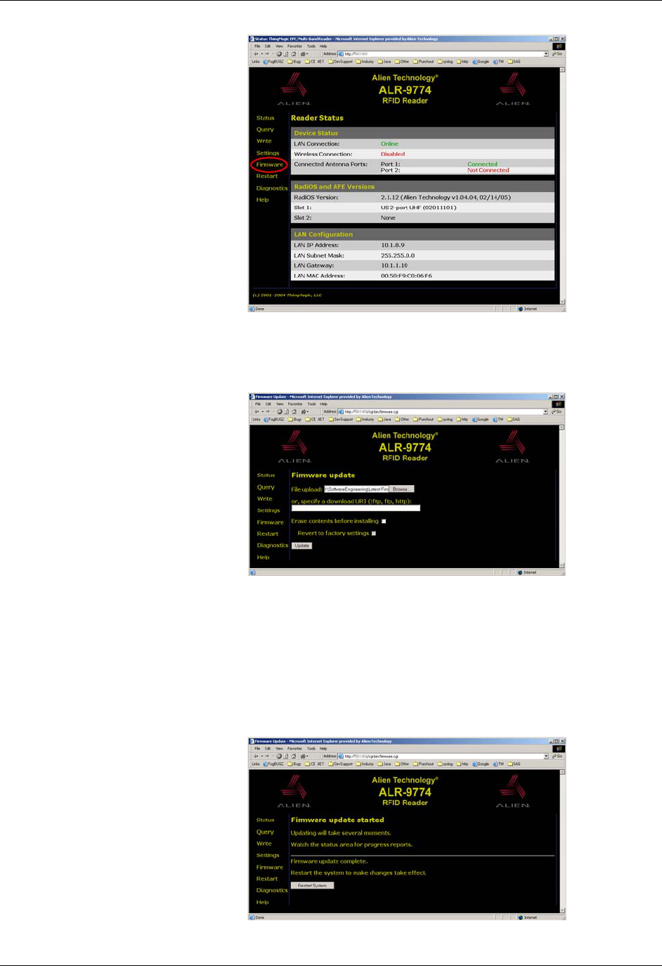
APPENDIX B UPGRADING READER FIRMWARE
READER INTERFACE GUIDE
DOC. CONTROL # 8101938-000 REV 05
95
Click the "Firmware" link to navigate to the Firware Upgrade screen:
Next, click the "Browse…" button and navigate to the appropriate firmware file
provided by Alien Technology and click the "Upgrade" button. Leave the "Erase
contents before installing" and "Revert to factory settings" checkboxes
unchecked.
After the file has been uploaded and and installed, you will be asked to restart
the reader. Do this by clicking the "Restart System" button:

UPGRADING READER FIRMWARE APPENDIX B
READER INTERFACE GUIDE
DOC. CONTROL # 8101938-000 REV 05
96
While the reader is restarting (it takes approximately one minute), you will see
the following screen:
After the reader restarts, the web interface attempts to reload the Status page. If
the reader is configured to acquire its network information from a DHCP server, it
may acquire a new IP address when it restarts, which may cause the Status
page to not load. Simply browse to the reader's new IP address and verify the
new firmware by checking the "RadiOS Version" area of the Status page.