Alien Technology BHNPR001 NanoScanner User Manual User guide
Alien Technology Corporation NanoScanner User guide
UserManual.wiki
>
Alien Technology
>
BHNPR001 User Manual
User guide
Navigation menu
Upload a User Manual
Namespaces
Wiki Guide
HTML
PDF
Info
Views
User Manual
Discussion / Help
Navigation


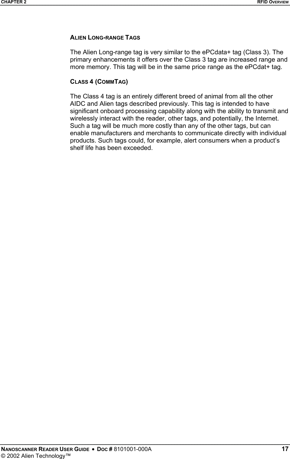
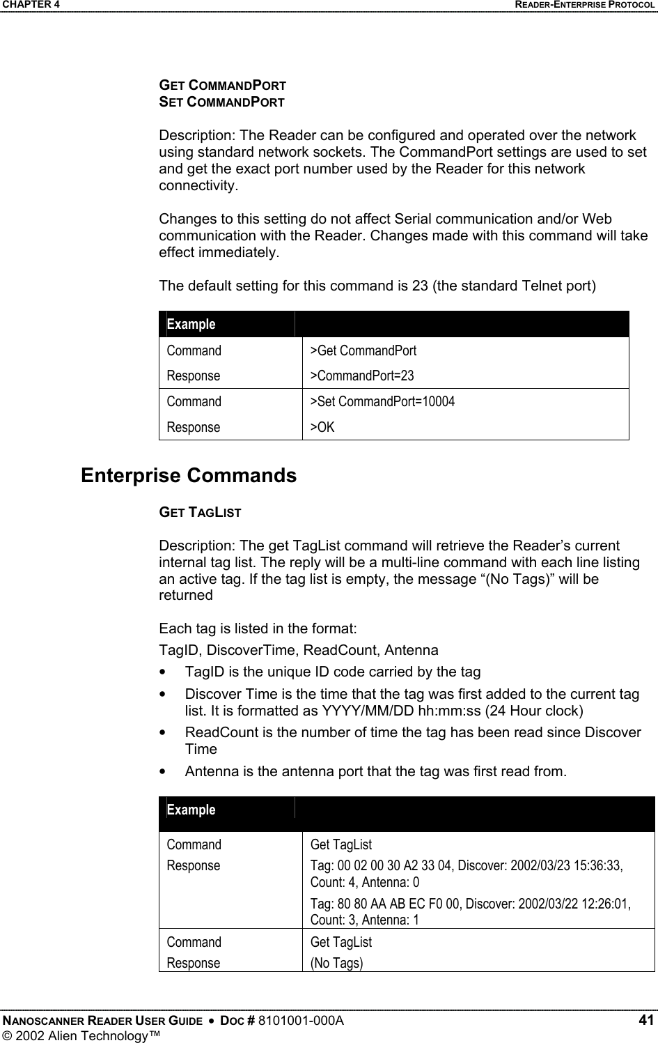
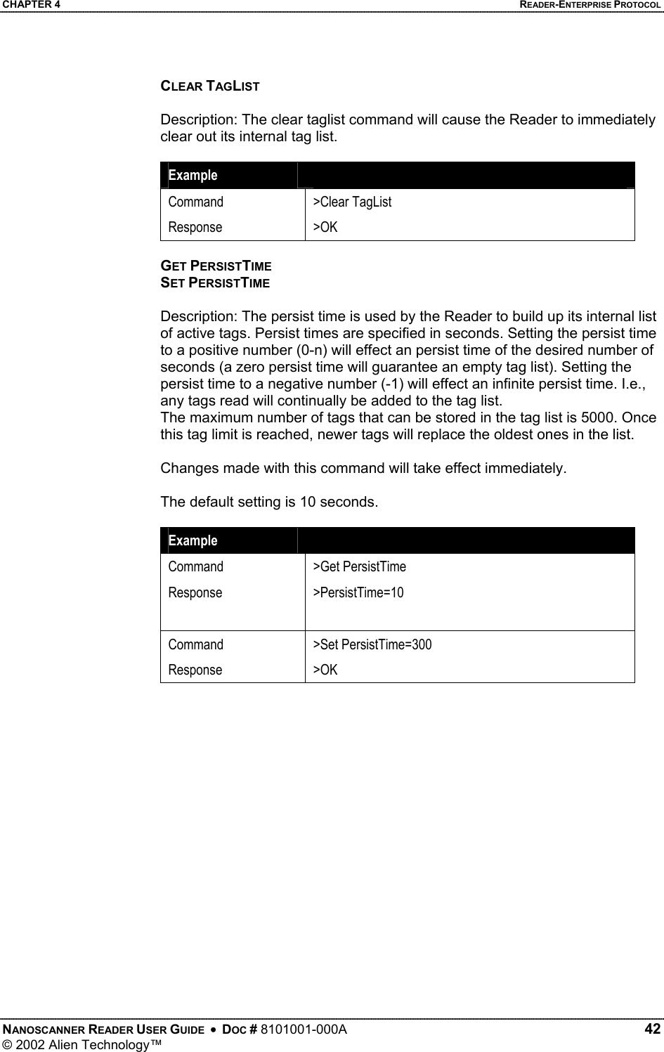
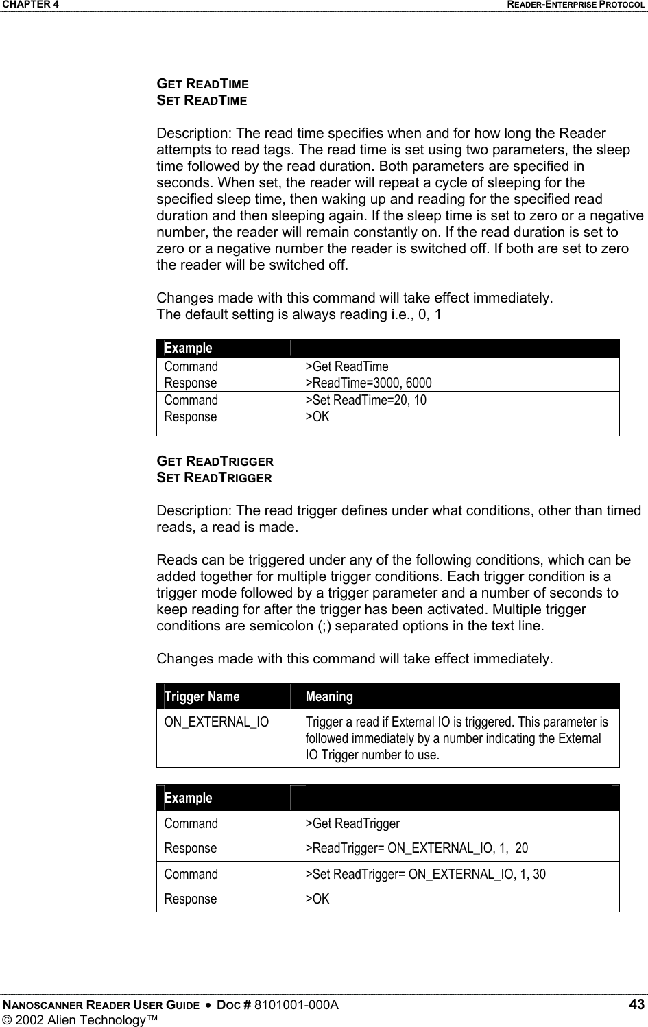
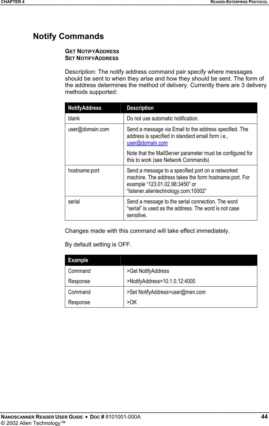
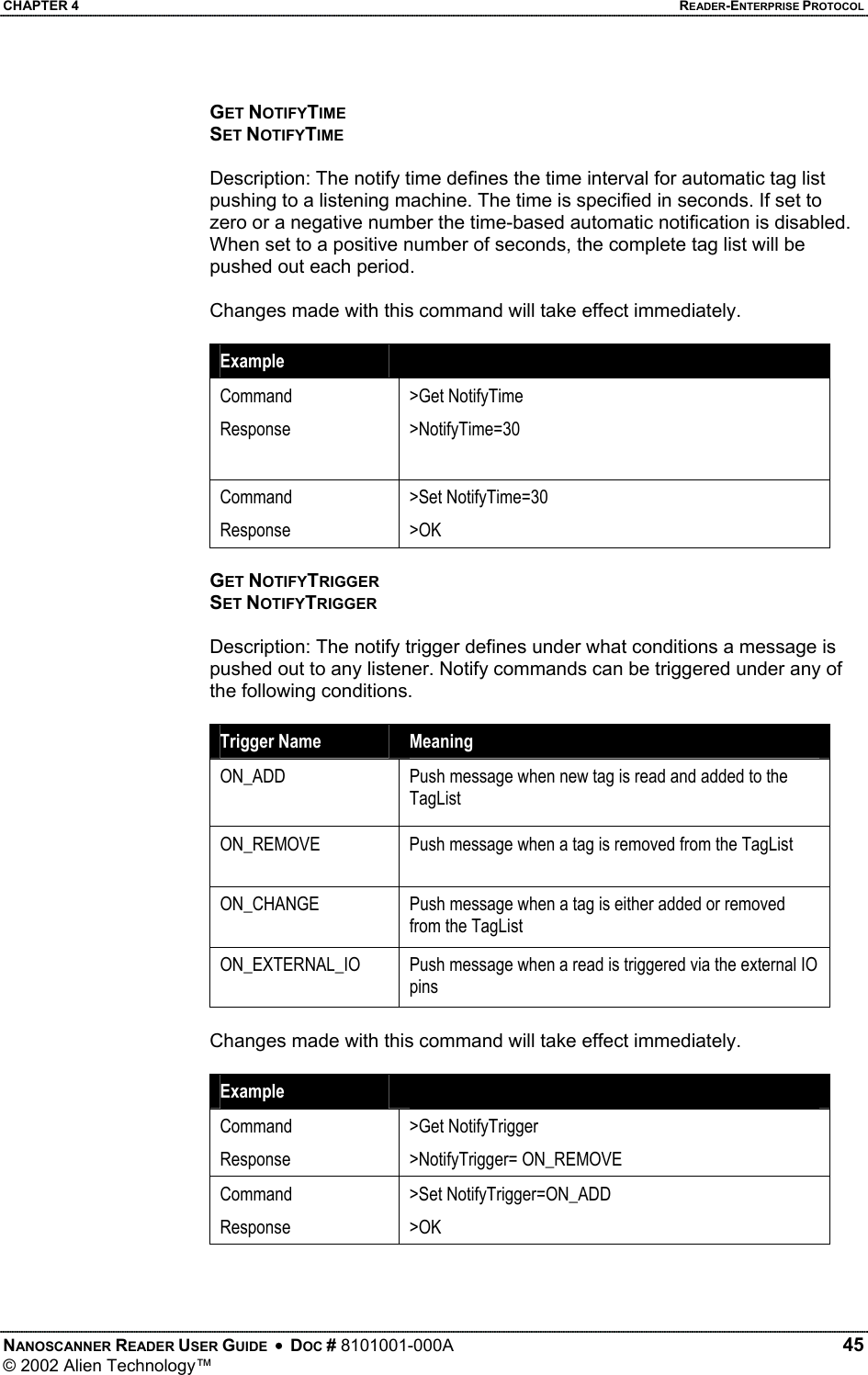
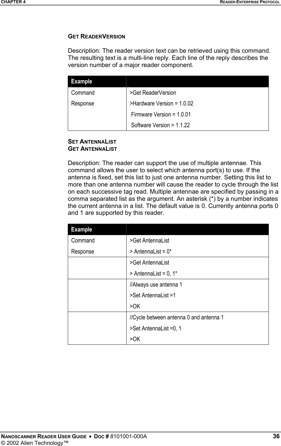
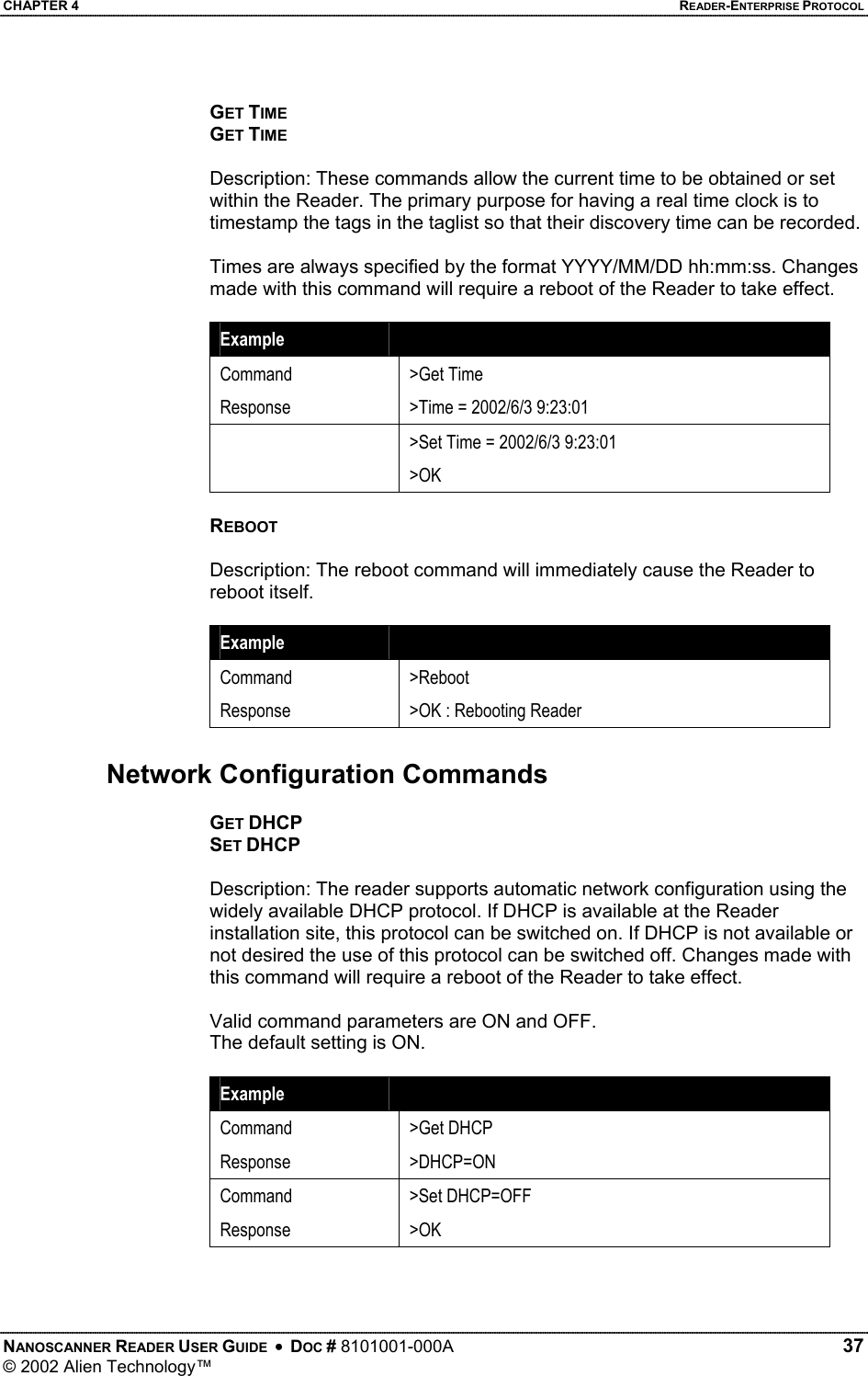
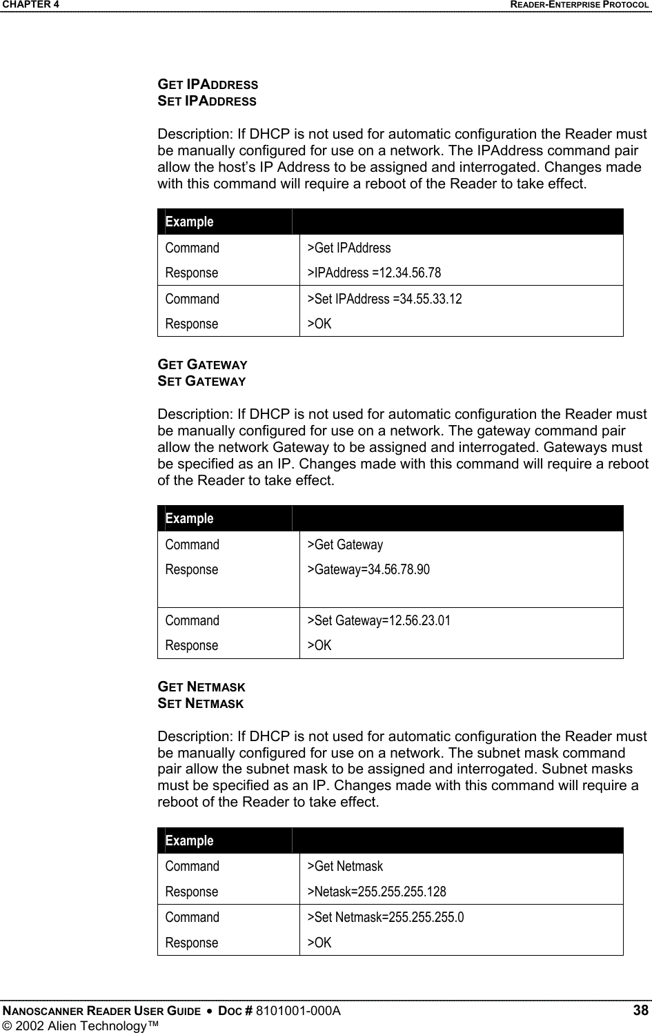
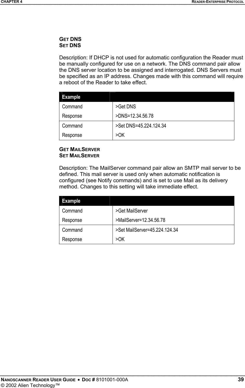
![CHAPTER 4 READER-ENTERPRISE PROTOCOL Commands Introduction Overview There are two distinct categories of Reader<->Enterprise command: those that are instantiated by the Enterprise host (Action commands), and those that instantiated by the Reader itself (Notify commands) Action Commands Action commands are instantiated by an Enterprise system, which creates and issues a command to the Reader. The Reader always responds to these commands with an immediate reply. Action commands are used to configure the reader, to operate it and to interrogate the tag lists. Notify Commands Notify commands are messages that are pushed out to the Enterprise by the Reader in response to some action. Once the Enterprise system has configured the Reader to push commands, the Reader is able to push tag lists out in response to some action or some time elapsing. This allows the Enterprise system to be notified on events, rather than constantly poll the reader for changes. Command Format All commands between the Enterprise system and the Reader are human readable ASCII text based messages. For example a command to set the logical name of the Reader using the Set Reader Name command takes the form: Set ReaderName = My Alien Reader [CR][LF] All commands to the reader are single line ASCII commands. These commands are always terminated by a single carriage return / line feed character pair [CR][LF], ascii code 0x0D followed by ascii 0x0A. All replies from the reader are either single line or multiple line ASCII replies. These replies are always terminated by a single carriage return / line feed character pair [CR][LF] followed by a NULL character, ascii codes 0x0D, 0x0A, 0x00. Where a reply comprises multiple text lines, each line is separated by a single carriage return / line feed character pair [CR][LF], ascii code 0x0D followed by ascii 0x0A. An example of a single line command / response is: >Get ReaderName[CR][LF] >ReaderName = Alien Reader[CR][LF][0] An example of a multiple line command / response is: >Get ReaderVersion[CR][LF] >ReaderVersion = 1.0[CR][LF] NANOSCANNER READER USER GUIDE • DOC # 8101001-000A 32 © 2002 Alien Technology™](https://usermanual.wiki/Alien-Technology/BHNPR001/User-Guide-255485-Page-36.png)
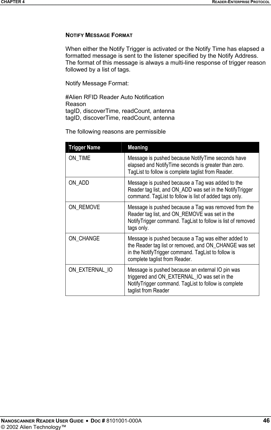
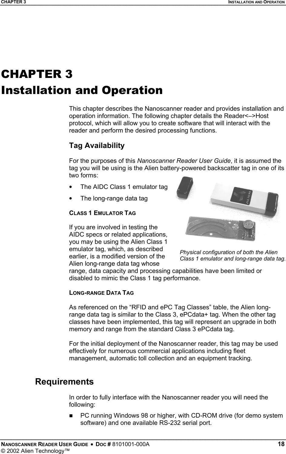
![CHAPTER 4 READER-ENTERPRISE PROTOCOL FirmwareVersion = 1.0[CR][LF] SoftwareVersion = 1.0[CR][LF][0] Commands are case insensitive. i.e., set readername is equivalent to Set ReaderName Suppressing Command Prompts By default all commands are set up for interactive use over a serial console or telnet style interface. Consequently replies are always followed by a command prompt indicating user input is required. Often this command prompt is not required, especially when client software is written that programmatically communicates with the reader. To account for these applications, all command prompts can be suppressed by making the first character of any command be an 0x1 character. For example, Interactive Command Format: Alien> get ReaderName[CR}[LF] ReaderName = Alien Reader[CR][LF][0] Alien>[CR][LF] Non-Interactive Command Format: [1]get ReaderName[CR][LF] ReaderName = Alien Reader[CR][LF][0] General Commands Command Description Get ReaderName Set ReaderName Allows an arbitrary name to be associated with and retrieved from the Reader. Get ReaderType Get a description of the Reader type Get ReaderVersion Get the Reader software/hardware versions. Get AntennaList Set AntennaList Get and Set the antenna port list the Reader should use. Get Time Set Time Get and Set the real time clock on the Reader. Reboot Reboot the Reader. NANOSCANNER READER USER GUIDE • DOC # 8101001-000A 33 © 2002 Alien Technology™](https://usermanual.wiki/Alien-Technology/BHNPR001/User-Guide-255485-Page-37.png)

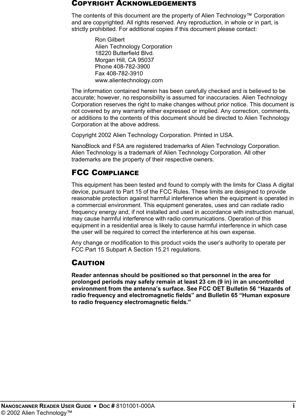
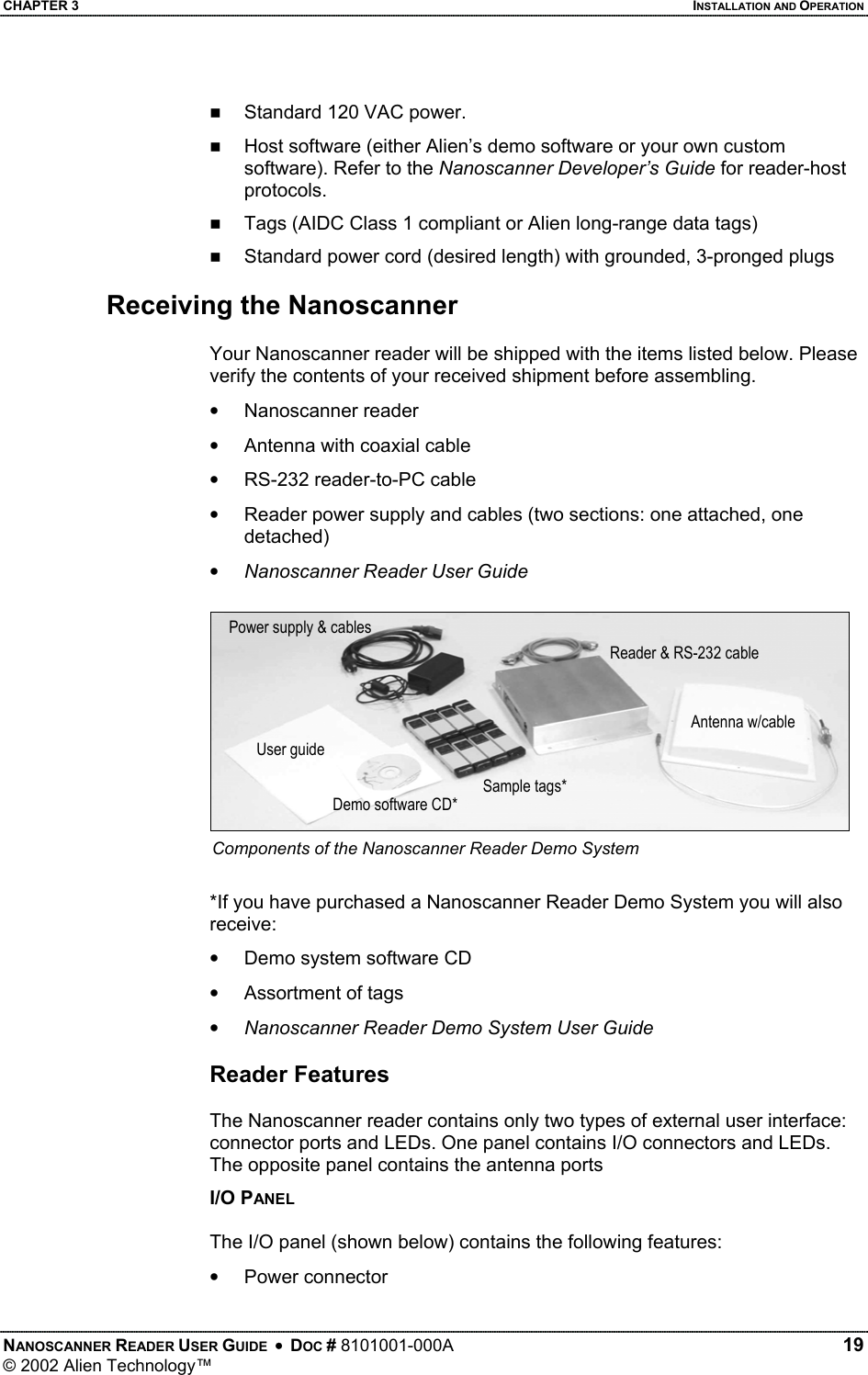
![CHAPTER 4 READER-ENTERPRISE PROTOCOL GET HEARTBEATPORT SET HEARTBEATPORT Description: The Reader can be configured to periodically send out a Heartbeat message to the network. This heartbeat takes the form of a single UDP packet (Universal Datagram Packet) broadcast out to the entire subnet that the Reader is configured for. The actual port number that this packet is sent out to is configured using the HeartbeatPort command. Listening for this heartbeat can be used to initially locate a Reader on a network and subsequently make sure that the Reader is still alive. Changes made with this command will take effect immediately. The default setting for this command is 3988 The format of the UDP packet is a single text line containing three comma separated fields terminated with a NULL character: ReaderName, ReaderType, ReaderCommandPort i.e., “Loading Dock Reader A, Alien Class I Reader, 4002[0]” Example Command Response >Get HeartbeatPort >HeartbeatPort=3004 Command Response >Set HeartbeatPort=10002 >OK GET HEARTBEATTIME SET HEARTBEATTIME Description: The Reader can be configured to periodically send out a Heartbeat message to the network. This heartbeat takes the form of a single UDP packet (Universal Datagram Packet) broadcast out to the entire subnet that the Reader is configured for. The time interval between heartbeats can be specified and interrogated using this command. All intervals are specified in seconds. A setting of zero will suspend the output of any further heartbeats. Changes made with this command will take effect immediately. The default setting for this command is 30 seconds. Example Command Response >Get HeartbeatTime >HeartbeatTime=30 Command Response >Set HeartbeatTime=60 >OK NANOSCANNER READER USER GUIDE • DOC # 8101001-000A 40 © 2002 Alien Technology™](https://usermanual.wiki/Alien-Technology/BHNPR001/User-Guide-255485-Page-44.png)