Alien Technology BHNPR001 NanoScanner User Manual User guide
Alien Technology Corporation NanoScanner User guide
User guide


COPYRIGHT ACKNOWLEDGEMENTS
The contents of this document are the property of Alien Technology™ Corporation
and are copyrighted. All rights reserved. Any reproduction, in whole or in part, is
strictly prohibited. For additional copies if this document please contact:
Ron Gilbert
Alien Technology Corporation
18220 Butterfield Blvd.
Morgan Hill, CA 95037
Phone 408-782-3900
Fax 408-782-3910
www.alientechnology.com
The information contained herein has been carefully checked and is believed to be
accurate; however, no responsibility is assumed for inaccuracies. Alien Technology
Corporation reserves the right to make changes without prior notice. This document is
not covered by any warranty either expressed or implied. Any correction, comments,
or additions to the contents of this document should be directed to Alien Technology
Corporation at the above address.
Copyright 2002 Alien Technology Corporation. Printed in USA.
NanoBlock and FSA are registered trademarks of Alien Technology Corporation.
Alien Technology is a trademark of Alien Technology Corporation. All other
trademarks are the property of their respective owners.
FCC COMPLIANCE
This equipment has been tested and found to comply with the limits for Class A digital
device, pursuant to Part 15 of the FCC Rules. These limits are designed to provide
reasonable protection against harmful interference when the equipment is operated in
a commercial environment. This equipment generates, uses and can radiate radio
frequency energy and, if not installed and used in accordance with instruction manual,
may cause harmful interference with radio communications. Operation of this
equipment in a residential area is likely to cause harmful interference in which case
the user will be required to correct the interference at his own expense.
Any change or modification to this product voids the user’s authority to operate per
FCC Part 15 Subpart A Section 15.21 regulations.
CAUTION
Reader antennas should be positioned so that personnel in the area for
prolonged periods may safely remain at least 23 cm (9 in) in an uncontrolled
environment from the antenna’s surface. See FCC OET Bulletin 56 “Hazards of
radio frequency and electromagnetic fields” and Bulletin 65 “Human exposure
to radio frequency electromagnetic fields.”
NANOSCANNER READER USER GUIDE • DOC # 8101001-000A i
© 2002 Alien Technology™

TABLE OF CONTENTS
Alien Technology
Nanoscanner™
Reader User Guide
Table of Contents
.....................................................................................................1 CHAPTER 1
.............................................................................................1 INTRODUCTION
..........................................................................................................1 AUDIENCE
....................................................................1 NANOSCANNER READER OVERVIEW
............................................................................................1 Requirements
............................................................................................2 Specifications
.....................................................................................................4 CHAPTER 2
............................................................................................4 RFID OVERVIEW
..........................................................................................4 RFID VS BARCODES
..........................................................................................6 RFID COMPONENTS
...............................................................................6 Reader or Interrogator
.................................................................................................7 Antenna(s)
...........................................................................................................8 Tags
Host Computer and Input/Output Functions............................................13
.....................................................14 MIT, AIDC AND THE RFID (EPC) INITIATIVE
....................................................................15 RFID and ePC Tag Classes
...................................................................................................18 CHAPTER 3
.............................................................18 INSTALLATION AND OPERATION
........................................................................................18 Tag Availability
...............................................................................................18 REQUIREMENTS
........................................................................19 RECEIVING THE NANOSCANNER
.....................................................................................19 Reader Features
...............................................................21 SYSTEM ASSEMBLY AND BENCH TEST
..........................................................................21 BenchTest Connections
.............................................................................24 Bench Test Procedure
..............................................................................................25 SYSTEM DESIGN
..................................................................................................25 INSTALLATION
..........................................................................................25 Requirements
NANOSCANNER READER USER GUIDE • DOC # 8101001-000A ii
© 2002 Alien Technology™

TABLE OF CONTENTS
Installation Procedure..............................................................................26
SYSTEM OPERATION ........................................................................................28
CHAPTER 4...................................................................................................29
READERENTERPRISE PROTOCOL .......................................................29
OVERVIEW .......................................................................................................29
DOCUMENT SPECIFICATIONS ............................................................................29
INTRODUCTION.................................................................................................30
Reader Tag List.......................................................................................30
Persist Time ............................................................................................30
COMMUNICATION PROTOCOL ............................................................................31
Overview..................................................................................................31
Serial Communication .............................................................................31
Network Communication .........................................................................31
Web Based Communication....................................................................31
COMMANDS INTRODUCTION ..............................................................................32
Overview..................................................................................................32
Action Commands ...................................................................................32
Notify Commands....................................................................................32
Command Format ...................................................................................32
Suppressing Command Prompts ............................................................33
General Commands ................................................................................33
Network Configuration Commands .........................................................34
Enterprise Commands.............................................................................34
Notify Commands....................................................................................35
GENERAL COMMANDS ......................................................................................35
NETWORK CONFIGURATION COMMANDS............................................................37
ENTERPRISE COMMANDS..................................................................................41
NOTIFY COMMANDS .........................................................................................44
NANOSCANNER READER USER GUIDE • DOC # 8101001-000A iii
© 2002 Alien Technology™

CHAPTER 1 INTRODUCTION
CHAPTER 1
Introduction
The Nanoscanner Reader User Guide provides basic instructions for
installing and operating the Nanoscanner reader. It also includes an overview
of RFID technology and covers the reader firmware protocol in detail.
This book is designed for use by those who wish to develop software
products and extended systems that take full advantage of the Nanoscanner
reader’s capabilities.
Audience
For the purposes of this book, we assume the readers of the Nanoscanner
Reader User Guide:
Are competent PC users.
Have minimal previous knowledge of radio-frequency identification
technology.
Are experienced in software development and/or hardware systems
integration.
Nanoscanner Reader Overview
The Nanoscanner is delivered with the following components and
accessories:
Nanoscanner reader
External antenna and coaxial cable
One RS-232 serial cable (for host computer)
Power supply
Nanoscanner Reader User Guide
Requirements
In order to fully interface with the Nanoscanner reader you will need the
following:
PC running Windows 98 or higher, with CD-ROM drive and one available
RS-232 serial port.
Standard 120 VAC power.
NANOSCANNER READER USER GUIDE • DOC # 8101001-000A 1
© 2002 Alien Technology™

CHAPTER 1 INTRODUCTION
Host software (Alien demo software or your own custom software) Refer
to the Nanoscanner Reader Developer’s Guide for reader-host protocols.
RFID Tags (AIDC Class 1 compliant)
Standard power cord (desired length) with grounded, 3-pronged plugs
Specifications
Specifications for key components of the Nanoscanner reader system are
provided in the tables below:
NANOSCANNER READER
Name Nanoscanner Reader
Part Number BHNPR001
Architecture Point-to-multipoint reader network
Frequency 902.6 MHz – 927.4 MHz
Hopping Channels 63
Channel Spacing 400 KHz
Channel Dwell Time < 0.4 Seconds
RF Transmitter < 30 dBm
Modulation Method On Off Keying (OOK)
20 db Modulation Bandwidth < 400 KHz
RF Receiver 2 channels
Power Consumption 25 Watts (120 VAC at 500 mW)
Communications Interface RS-232, LAN TCPI/IP
Inputs/Outputs 2 coax antenna, 8 logic I/O, comm ports, power
Dimensions (L) 19 cm (7 in) x (W) 26 cm (10 in) x (D) 5 cm (2 in)
Weight Approximately 1.8 kg (4 lb)
Operating Temperature -40° C to +85° C (-40 °F to + 85°F)
NANOSCANNER READER EXTERNAL ANTENNA
3 dB Beamwidth E-plane: 65 degrees • H-plane: 65 degrees
Frequency 902-928 MHz
Gain (dBi) 5.73 dBi
Polarization Circular
RF Connector Reverse-thread SMA
VSWR 1.5:1
Dimensions (cm) 22 x 27 x 4 • (in) 8.5 x 10.5 x 1.65
Weight .57 kg • 1.25 lb
NANOSCANNER READER USER GUIDE • DOC # 8101001-000A 2
© 2002 Alien Technology™
CHAPTER 1 INTRODUCTION
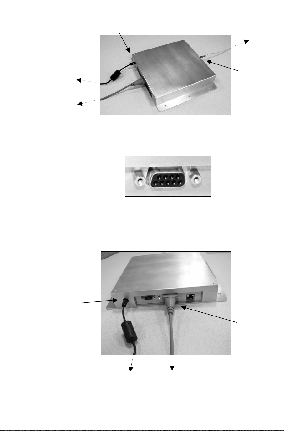
RS-232 PORT PINOUTS
RS232 Connector (Female DB-9F)
Pin 1 DCD Connected to Pin 6
Pin 2 TR1 Transmit Data (Output)
Pin 3 RC1 Receive Data (Input)
Pin 4 DTR Connected to Pin 6
Pin 5 Ground
Pin 6 DSR Connected to Pin 4
Pin 7 RTS Connected to Pin 8
Pin 8 CTS Connected to Pin 7
Pin 9 Not Connected
NANOSCANNER READER USER GUIDE • DOC # 8101001-000A 3
© 2002 Alien Technology™
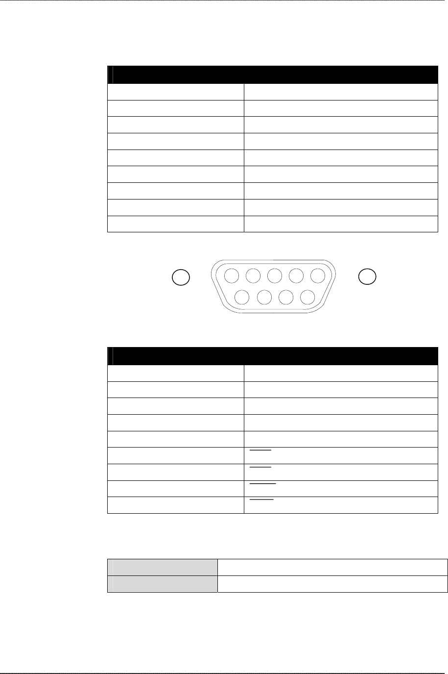
I/O Port Connector (Male DB-9M)
Pin 1 CTL0
Pin 2 CTL1
Pin 3 TRIG0
Pin 4 TRIG1
Pin 5 Ground
Pin 6 CTL0
Pin 7 CTL1
Pin 8 TRIG0
Pin 9 TRIG1
54321
9 8 7 6
OTHER COMPONENTS
RS-232 Serial Cable DB-9 male/female serial
Antenna Port 1 Plug Reverse thread 50 ohm terminator

CHAPTER 2 RFID OVERVIEW
CHAPTER 2
RFID Overview
Radio-frequency identification (RFID) technology uses radio frequency
signals to acquire data remotely from tags within read (or “interrogation”)
range. The data is then used for a variety of purposes such as opening doors
and gates, paying tolls or tracking equipment and materials.
Although RFID can be deployed in a number of frequency bands, the
products referred to in this book operate exclusively in the UHF band,
specifically, in the frequency band centered at 915 MHz (902-928 MHz).
This equipment—as well as many cordless telephones and other wireless
devices—operates in this frequency band, which does not require its users
to be licensed.
RFID vs Barcodes
RFID is similar in some ways to barcode technology in that the tags or labels
contain ID and other data readable by electronic equipment.
READ RANGE AND INTERFERENCE
An important advantage of RF over barcodes is that RF tags do not require
“line of sight” to be read. That is—while a barcode must be scanned directly
by a laser beam and cannot be read if something opaque stands between
the reader/scanner and the label—RF tags can be read through a great
many materials, including boxes and other radiolucent products.
The effective range of a laser-based barcode system is limited because with
increased distance comes an increased chance of materials passing
between the reader’s laser and the barcode label. Attempts in the past to use
barcodes for tollway use or railcar identification, for example, failed because
the vehicle speed—combined with the increased likelihood of rain, snow or
debris interrupting the laser’s line-of-sight at the crucial moment of
passage—rendered the technology very unreliable for these applications.
VISIBILITY OF PALLETS, CASES AND INDIVIDUAL ITEMS
In manufacturing, supply chain and retail/commercial applications, barcodes
have been very effective for over 25 years. The line-of-sight and range
limitations have been manageable for those environments where products or
cases of products moved slowly past a reader at close distances.
Barcodes themselves can contain (and convey) information about
manufacturer, product family and type, and perhaps even the specific
NANOSCANNER READER USER GUIDE • DOC # 8101001-000A 4
© 2002 Alien Technology™

CHAPTER 2 RFID OVERVIEW
manufacturing lot. These capabilities have improved the speed and handling
of products and materials around the world.
However, barcodes cannot identify a specific case of paper towels that is in
the center of a pallet surrounded by other cases of towels. And barcodes
cannot record the temperatures a perishable product has been exposed to
and calculate a more realistic expiration date for that specific item.
Neither can barcode systems identify an individual carton of milk as it rolls
down the checkout conveyor and alert the cashier that its contents may be
spoiled. And barcodes cannot alert the merchant of products in the
consumer’s pocket that have not been paid for.
RFID systems have the potential to do all of these things; a laser-based
barcode system cannot.
Although RFID is being developed initially for use in the supply side of many
businesses (shipping, receiving, warehousing, stocking, inventory, etc.), this
technology makes it not only possible, but realistic to one day track the
movement of individual products throughout a retail store and to identify
critical characteristics about the item.
For the near term, businesses will benefit from automatically logging
shipments and receipts of products moving in and out through their loading
docks. They will be able to track the movement of products within their own
facilities to improve efficiency, and reduce theft and shrinkage.
READ/WRITE TAG DATA
Barcode data is fixed the moment the label is printed. It can never be
changed unless a new label is printed and attached. On the other hand,
many RFID tags can be reprogrammed in the field to reflect current
information such as storage location or date placed in service.
More sophisticated RFID tags can also record dynamic conditions (such as
temperature or meter usage) as they change, then transfer the current
conditions (or a record of conditions) to a reader upon request.
THE RFID ADVANTAGE
In short, RFID raises the standard for automatic identification technology and
allows it to perform more valuable functions than have been possible with
barcodes.
NANOSCANNER READER USER GUIDE • DOC # 8101001-000A 5
© 2002 Alien Technology™
CHAPTER 2 RFID OVERVIEW
RFID Components
Any RFID system needs certain basic components. These include:
Transmitter
NANOSCANNER READER USER GUIDE • DOC # 8101001-000A 6
© 2002 Alien Technology™
Receiver
Microprocessor
Usually combined in a “reader” or “interrogator.”
Antenna(s)
Tags
Output device(s) and/or host computing device
(Optional) input device(s)
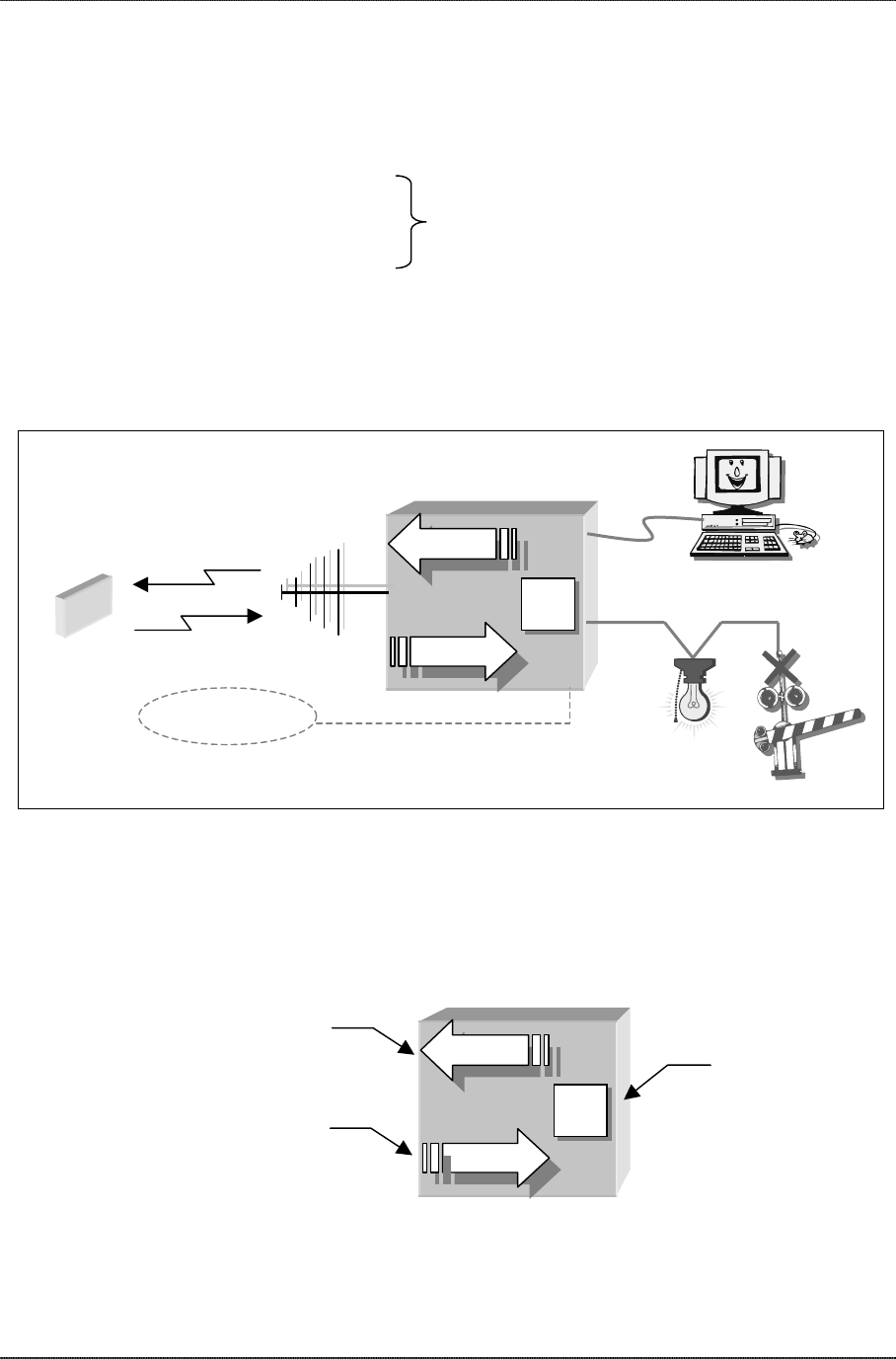
ANTENNA
TAG Transmit
HOST
Receive
READER
OUTPUT
DEVICES
INPUT DEVICES
(Optional)
RFID system components
Reader or Interrogator
A reader may be referred to as an “interrogator” because it asks (or
interrogates) tags for their ID information and any other data they may
contain.
Because the transmitter and receiver functions are working together, the
reader may also be referred to as a “transceiver.”
Transmitter
Transmit Microprocessor
Receiver
Receive
READER

CHAPTER 2 RFID OVERVIEW
No matter what it may be called, the reader typically contains a:
transmitter,
receiver, and
microprocessor.
The reader unit also contains an antenna as part of the entire system (see
below).
Antenna(s)
The antenna broadcasts the RF signals generated inside the reader’s
transmitter into the immediate environment. The antenna also receives
responses from tags within range.
In general, readers may use one or more antennas to detect and interrogate
tags. For this system, however, only one antenna can be active at a time.
CAUTION: Reader antennas should be positioned so that personnel in the
area may safely remain at least 23 cm (9 in) from the antenna’s surface. See
FCC OTE Bulletin 56 and 65 for further details.
HOW ACTUAL ANTENNAS LOOK
Although the antennas in our diagrams are often depicted like fish bones, it is
unlikely you will see RFID antennas like this in the field.
Reader Antennas. Most reader antennas are housed in enclosures and will
look like plain, shallow boxes. In some cases, the antenna may actually be
contained inside the reader enclosure (which may also look like a plain box).
Tag Antennas. Tag antennas are often nothing more than etched or printed
metallic patterns on a circuit board or thin film inside a small case or
sandwiched between layers of a printed label.
READER ANTENNA
In enclosure
TAG ANTENNA TAG CASE
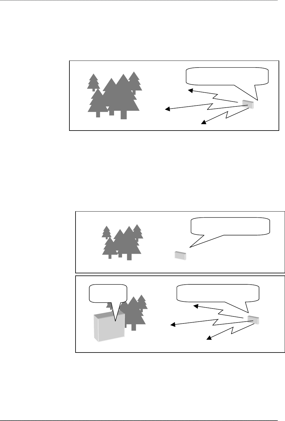
FOOTPRINT, POLARIZATION AND READ RANGE
Antennas have patterns or “footprints” that describe the area in which their
energy is most effective. Although the word footprint suggests a two-
dimensional area, the pattern actually exists in three dimensions and is more
like a large, irregularly shaped balloon (think of an inflated surgical glove).
NANOSCANNER READER USER GUIDE • DOC # 8101001-000A 7
ANTENNA & read range
© 2002 Alien Technology™ © 2002 Alien Technology™

CHAPTER 2 RFID OVERVIEW
Although an antenna may manifest its energy in a certain pattern, how your
system can use that energy depends on a great many factors including
antenna characteristics, tag and reader characteristics, the nature of the
items tagged, and the changing nature of the reading environment.
Polarization. Polarization of an antenna, expressed simply, means there is a
preferred orientation of the tag to the reader antenna’s energy field, which
may optimize the system’s ability to read tags, particularly under less than
ideal conditions. Under most normal conditions, and within the read range for
the system, all functioning tags should be readable. However, it may be
possible to read tags well beyond the specified read range if they are
oriented in the antenna’s preferred direction. Keep in mind, however, that
some systems may be designed to limit, rather than maximize, the read
range and thus may use polarization to facilitate tag discrimination.
Footprint Size and Read Range. The size of the antenna footprint and the
range at which a given tag may be read are affected, in various degrees, by
such factors as the output power of the transmitter, the receiver sensitivity,
the type of tag (and its own internal antenna) and the tag’s position relative to
the reader antenna. The reading environment also plays an important part in
determining how far out and where, in relation to the antenna, tags can and
cannot be read.
Because an antenna’s pattern is often irregularly shaped, you may get a read
at long range in one spot, then move the tag a few inches to one side and not
be able to get the tag to read again until you have moved it several feet
closer to the antenna.
Tags
RF tags are devices—similar in principle to barcodes or even name
badges—that contain identification and other information that can be
communicated to a reader from a distance. However, RF tags can contain
much more information than a barcode, can be read at greater distances and
under more challenging conditions, and in some cases can accept new data
in the field.
TAG-TO-READER COMMUNICATIONS
Tags are often classified as either “passive” or “active” to describe how they
communicate with the reader. Passive means, simply, that the tag uses a
modified form of the reader’s own signal to send back its data. Active means
the tag contains its own transmitter.
NANOSCANNER READER USER GUIDE • DOC # 8101001-000A 8
© 2002 Alien Technology™
CHAPTER 2 RFID OVERVIEW
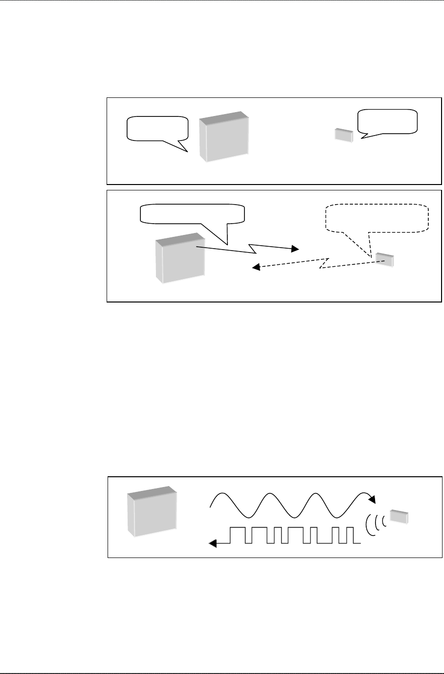
(Passive) Backscatter Tags. A passive tag uses a method called
“modulated backscatter” to convey its data to the reader. Essentially, the tag
reflects (or backscatters) the RF signal transmitted by the reader and
embeds its unique ID and data by modulating that reflected signal.
Z Z Z z z z
Z Z Z z z z
TAG
READER
“What’s your name?” “What’s your name?”
MY NAME IS GORT.
Backscatter TAG
READER
NANOSCANNER READER USER GUIDE • DOC # 8101001-000A 9
© 2002 Alien Technology™
Passive tags reply by reflecting the reader’s own RF signal, with unique tag data
embedded in the modulated “backscatter.”
• Modulated backscatter is similar to sending messages between distant
mountaintops by bouncing sunlight off mirrors using Morse Code
patterns of on and off. In this scheme, communication is only possible
when the light source is present.
The reader transmits a continuous-wave (CW) RF signal into the reading
environment. When a tag appears in the area, it modulates, or breaks
up, that CW signal into patterns of ones and zeroes that define the tag’s
digital data. Because it “speaks” essentially by reflecting the reader’s
“voice,” a backscatter tag is physically incapable of communicating data
outside the presence of a reader’s signal.
TAG
READER
The reader transmits a continuous wave signal. The tag breaks up (modulates) that
signal into patterns of ones and zeroes that convey its data to the reader.
(Active Tags) Transmitters and Transponders. Active tags, unlike passive
backscatter tags, contain their own transmitters, or tiny radio stations. Active
tags may be considered to be either transmitters or transponders, though, to
be precise, a transponder is always a transmitter tag, but not all transmitter
tags are transponders, as you will see below.
CHAPTER 2 RFID OVERVIEW
Transmitters. A transmitter tag can broadcast a message into the
environment even if there is no reader active nearby to “hear” it. This tag
is like a telephone can ring even when no one is home to answer it.
MY NAME IS GORT...MY
NAME IS GORT...MY NAME...
TAG
Active tags (transmitters) contain their own little radio stations and can transmit
messages even the absence of a reader.
Transponders. To conserve power, or to minimize RF noise pollution,
some active/transmitter tags may be configured to “go to sleep” or enter
a quiescent or lower-power state when not being interrogated. When a
reader enters the area, it then transmits a signal to “wake up” all the tags
in that area. Each tag thus only transmits in response to the reader’s
command. This type of active tag is called a “transmitter/responder” or
“transponder.”
ZZzzz ZZzzz Hello? ZZzzz
ZZzzz Hello? ZZzzz ZZzzz
TAG
NANOSCANNER READER USER GUIDE • DOC # 8101001-000A 10
© 2002 Alien Technology™
Active tags that are considered transponders (transmitter/responders) go into a
quiescent or low power state (“sleep”) until awakened by a reader.
READER
MY NAME IS GORT...MY
NAME IS GORT...MY NAME...
Wake up
and speak!
TAG
CHAPTER 2 RFID OVERVIEW
CAUTIONS REGARDING TERMS AND EXPRESSIONS
The authors of this manual have chosen to use the simplest and most precise
definitions of RFID terms to make the concepts as clear as possible throughout
this text.
However, you should be aware of alternative definitions and uses of these
same terms, which you may encounter elsewhere in the industry. To be sure of
precise meaning, always clarify how these terms are being defined. The terms
most often misused or used inconsistently are:
• Active/passive/semi-passive
• Transponder vs tag
Active/Passive/Semi-Passive. This book uses active and passive to describe
whether a tag has a transmitter (active) or uses modulated backscatter to
communicate with the reader (passive) as detailed in this section. However,
many industry professionals refer to active and passive in terms of tag power,
with active referring to battery power and passive referring to tags energized by
the reader’s RF signal (or “beam-powered”). In this scheme, a third term, semi-
passive, is sometimes used to refer to tags that have a battery but which also
use part of the RF signal’s beam to energize their circuits for backscattering
data to the reader. A third definition of active and passive may refer to whether
or not a tag has an onboard processor.
Transponder vs Tag. A growing trend in the industry is to refer to any RFID
tag as a transponder. However, in the purest sense, while a transponder can
be called a tag, not every tag is a transponder. Formed from the words
transmitter and responder, the word transponder implies that the tag must first
be an active transmitter, though it may be designed to respond and transmit
only when a reader is nearby and sends the correct wake-up signal.
TAG POWER
Tags can be powered either by the RF signal from a reader (RF “beam”
powered) or by direct sources of energy such as batteries or wired power
connections. A battery generally gives a tag more range and can allow it to
perform independent functions.
RF energy
READER TAG
Beam-powered tags are powered exclusively by the energy in the RF signal
transmitted by the reader.
+Or
TAG BATTERY WIRED POWER CONNECTION
NANOSCANNER READER USER GUIDE • DOC # 8101001-000A 11
© 2002 Alien Technology™
Other tags receive power from batteries and, for special applications, may even be
wired to a power source.

CHAPTER 2 RFID OVERVIEW
Although beam power is used more often for passive tags, certain active tags
are capable of storing energy from a reader’s signal, then using that stored
energy to actively transmit data.
Tags (whether passive or active) that perform functions in addition to
providing their IDs (such as recording temperature or meter usage for later
transmission to a reader) normally require some kind of augmenting power
source.
TAG RANGE
Tag range, like antenna range, depends on much more than just the
characteristics of the tag. Reader power and sensitivity, antenna range and
polarization, and the reading environment can all affect the range at which a
given tag may be successfully read.
Certain attributes of the tag itself and its immediate surroundings also help
determine a tag’s full read range, including:
Tag power source (battery-powered tags typically have greater range
than those powered exclusively by the RF beam).
Type of materials between and around the tag and the reader.
Tag position relative to the antenna’s preferred orientation.
Relative tag speed (amount of time the tag is within read range, if either
the tag or the reader is moving relative to the other).
Amount and rate of data to be exchanged between tag and reader and
the overhead involved in error correction and other quality processes.
The tag antenna design.
Tags, like every other element in an overall system design, affect system
performance and should be configured to optimize the specific applications
they are to be used for.
TAG MEMORY
Tags may have just enough memory to hold only the simplest of information,
such as an ID code (little more than the amount of data on the average
barcode label), or may have as much memory and processing power as a
small computer. Tag memory may be read-only—or more accurately, write-
once-read-many (WORM)—or read/write (R/W):
WORM or Read-only Memory. Some tags are programmed once, either
at the factory or by the user, then locked to prevent reprogramming. The
data in these tags remains the same throughout the life of the tag.
Read/write Memory. Read/write tags can be reprogrammed in the field,
either by a dedicated programming device or by the reader itself. Some
read/write tags can also record dynamic information such as
temperature, usage, tilt and vibration, location, or date and time. When
such a tag is read, it can also transmit its currently stored data to an
authorized reader. The most sophisticated (transmitter) read/write tag
NANOSCANNER READER USER GUIDE • DOC # 8101001-000A 12
© 2002 Alien Technology™

CHAPTER 2 RFID OVERVIEW
may, in fact, function as a wireless computer, able to interact with other
tags and devices or link to the Internet.
Memory vs. Power. While tags with minimal memory capacity can easily
function on the tiny bit of energy provided by the RF signal alone, higher tag
memory and processing demands typically require the support of a battery or
other type of power source.
INPUT/OUTPUT AND ONBOARD PROCESSING (OPTIONAL)
Certain tags can be configured to perform onboard processing functions and
may be also have input/output (I/O) capabilities.
Inputs and Outputs. A tag may be connected to an input device, such as a
temperature sensor, a meter, or a tamper/tilt detector. Such tags can receive
data from the input device and then convey that data (either as a record of
changes over time or as the current value) to the reader upon request.
Outputs, on the other hand, allow a tag to activate an attached device such
as a LED or emit an audible tone (to signal its presence) or can enable or
disable connected devices. (For example, an attached tag could disable a
computer or other equipment if removed from authorized premises.)
Onboard Processing. Tags with onboard processing capabilities can
perform a variety of calculations or functions depending upon the tag’s
microprocessor and power source/consumption. Such tags might work in
concert with an input device, for example, recording the temperature
variations a perishable product has been exposed to over time, then
calculating a more realistic expiration date based on that history.
Host Computer and Input/Output Functions
In order to put the data acquired from a tag to practical use, the RFID system
needs either a host computer to process that data or some kind of output
function that responds to the tag data.
In many cases, both host computer and output functions are used in the
RFID system.
HOST COMPUTER
Through a host computer, the RFID system can log and process tag
transactions for a variety of purposes. For example:
In a warehouse, a tag read can be associated with a location and time
for the purposes of tracking objects and their movements.
In an automated toll system, a tag read can trigger a debit from the tag
owner’s account.
In an automated meter reading system, a tag read also includes gas or
water usage data that can be forwarded to a customer billing system.
OUTPUT FUNCTIONS
The simplest RFID system may only react with specified outputs according to
a set of rules programmed into the reader’s microprocessor. For example:
NANOSCANNER READER USER GUIDE • DOC # 8101001-000A 13
© 2002 Alien Technology™

CHAPTER 2 RFID OVERVIEW
In access control applications, a tag read whose ID is on a list of
authorized IDs can trigger the opening of a door or gate.
In warehouse applications, reading the tag on a specific pallet can turn
on a light, or ring a bell to indicate the desired case has been located.
INPUT FUNCTIONS (OPTIONAL)
An RFID system may also be designed to respond to certain input conditions.
Readers are often configured to interface with input devices such as
presence detectors. A presence detector can be used, for example, to power
up a reader only when an object is within range so as to conserve energy or
minimize the radio noise in a given environment.
MIT, AIDC and the RFID (ePC) Initiative
The Auto ID Center (AIDC) at the Massachusetts Institute of Technology
(MIT) is currently coordinating industry efforts to establish a new standard
system for identifying objects using RFID. In place of barcodes and UPCs
(universal product codes), objects would contain “ePCs” or electronic product
code tags or labels.
The benefits of ePCs are the same, in many ways, as those for generic RFID
in terms of its potential for increased range, ability to read through many
materials, read/write functionality and discrete identification of individual
objects.
The goal of the ePC initiative, however, goes beyond performance issues to
embrace practical issues as well, such as cost, logistics and fostering healthy
competition.
The final AIDC-endorsed standard will set price goals for products competing
in the new ePC marketplace. Compliant products will be required to conform
to certain configuration, interface and performance standards so that
competing products will remain compatible with one another, giving users a
range of suppliers from which to purchase their systems and ePC services.
The AIDC has defined four classes of RFID tags that will eventually address
the various ePC performance and price requirements of the marketplace, as
shown in the table below.
Alien Technology will have offerings in most of the AIDC classes plus special
tag configurations outside the AIDC spec for other applications.
The first class of tags to be introduced under this initiative (AIDC Class 1) will
be targeted primarily for use initially in manufacturing and supply-chain
operations to track movement of pallets, cases, cartons and other larger units
of product.
Once the technology has been integrated successfully into the supply side, it
will be introduced for widespread implementation at the individual item level.
Tests are currently being conducted to prove the efficacy of the RFID/ePC
technology in reducing theft of items from point-of-sale (POS) displays.
NANOSCANNER READER USER GUIDE • DOC # 8101001-000A 14
© 2002 Alien Technology™

CHAPTER 2 RFID OVERVIEW
RFID and ePC Tag Classes
ePC Tag Classes (AIDC and Alien)
TAG TYPE
TAG FEATURE
AIDC
1a
AIDC
1b
Alien
Class 1
Emulator*
AIDC
2
AIDC
3
Alien
Long
Range
AIDC
4
Proposed common tag name ePCID 64 ePCID 96 ePCID
emulator
ePCdata ePCdata+ Long-range
data tag
CommTag
1. Tag-to-reader communication mode
B = Backscatter (passive)
T = Transmitter (active)
B B B B B B T
2. Tag power
Beam = RF beam powered
Batt = battery or other power source
Beam Beam Batt Beam Batt Batt Batt
3a. Memory capacity (available to user)
64 bits 96 bits 64 bits TBD TBD 1k byte TBD
4. Memory type
WORM = Write-once, read-many
RW = Read/write
WORM WORM WORM RW RW RW RW
5. Onboard processing capability -- -- -- -- Yes Yes Yes
6. Range (optimal) 1 meter 1 meter 1 meter 1 meter <10 meters 15-30
meters
>100
meters
7. Cost range Lowest Lowest Medium Low Medium Medium High
8. Wireless Interactivity -- -- -- -- -- -- Yes
9. Market Introduction (est. timeframe) Oct 2002 TBD April 2002 TBD TBD July 2002 TBD
10. Core functionality Simple product ID, similar to UPC on
barcode
Product ID,
R/W
Product ID, R/W, I/O
w/battery for longer
range and onboard
processing
Wireless
communi-
cations +
ID
*The emulator tag is an Alien long-range data tag whose performance has been modified to
mimic the key attributes of Class 1 a and b tag performance.
The tag classes shown in this table reflect the classes (1–4) established by
the AIDC, along with two unique Alien tags.
This table cannot cover the vast range of RFID tags available today, but
rather represents those specifically related to the AIDC initiative and the
markets it addresses.
Proposed Common Names. These are suggested here to provide a short,
yet descriptive, name by which users and the general public may easily refer
to each of the broad tag categories.
• ePCID = lowest cost tags with read-only (or WORM) memory
• ePCdata = medium cost read/write tags with more memory (variations
offer additional functions and increased range)
• CommTag = highest cost transmitter/interactive communicator tags
NANOSCANNER READER USER GUIDE • DOC # 8101001-000A 15
© 2002 Alien Technology™

CHAPTER 2 RFID OVERVIEW
Each category may allow additional identifiers to be added to the core terms
to indicate variations within the type (as in the designation “ePCdata+” for an
ePCdata tag with a battery, or as in “ePCID 64” and “ePCID 96” indicating
the differences in user ID memory size)
CLASS 1 (EPCID TAGS)
Class 1 tags are most closely related to today’s barcode labels, thus they
may be referred to as the simplest component of the system: the “ePCID”
tag. They have a small amount of memory (the ePCID 64 has 64 bits versus
the UPC-14 which has 42 bits), they will be extremely affordable (price goal
is 5 cents), and can be made to fit most individual product packaging. Once
programmed, their data will remain fixed, making them read-only tags. These
tags will be powered by the reader’s RF beam exclusively.
ALIEN’S CLASS 1 EPCID EMULATOR TAG
This specially-modified Alien tag is being used to simulate ePCID tag
performance in interim tests of RFID viability for ePC and, specifically, supply
chain applications. Although it contains a battery, which can potentially
increase read range, this emulator tag has been tuned to the shorter range
(~1 meter) specified for the ePCID tags. Only 96 bits of the tag’s available
memory are used in this tag (64 bits for user ID), and its inherent capability
for I/O functions has been disabled.
CLASS 2 (EPC DATA TAGS)
Class 2 tags might logically be called “ePCdata” tags because they have the
same basic functionality as the ePCID tags but with three times the memory
(or more) and read/write data capability. This means new information can be
written into these tags either though a reader at a checkpoint or through input
devices connected directly to the tag. An ePCdata tag may, for example, be
linked to a temperature sensor. These tags will cost somewhat more than the
ePCID tags but will remain a low-cost choice for large-scale deployment.
CLASS 3 (EPCDATA+ TAGS)
The Class 3, ePCdata+ tags offer significant capabilities beyond those of the
basic ePCdata tag. The primary enhancement in these tags is their battery
power. However, this simple feature gives these tags significantly improved
range and memory and enables them to perform onboard processing.
Battery-powered tags represent an increase in both tag size and cost
(medium range).
NANOSCANNER READER USER GUIDE • DOC # 8101001-000A 16
© 2002 Alien Technology™

CHAPTER 2 RFID OVERVIEW
ALIEN LONG-RANGE TAGS
The Alien Long-range tag is very similar to the ePCdata+ tag (Class 3). The
primary enhancements it offers over the Class 3 tag are increased range and
more memory. This tag will be in the same price range as the ePCdat+ tag.
CLASS 4 (COMMTAG)
The Class 4 tag is an entirely different breed of animal from all the other
AIDC and Alien tags described previously. This tag is intended to have
significant onboard processing capability along with the ability to transmit and
wirelessly interact with the reader, other tags, and potentially, the Internet.
Such a tag will be much more costly than any of the other tags, but can
enable manufacturers and merchants to communicate directly with individual
products. Such tags could, for example, alert consumers when a product’s
shelf life has been exceeded.
NANOSCANNER READER USER GUIDE • DOC # 8101001-000A 17
© 2002 Alien Technology™
CHAPTER 3 INSTALLATION AND OPERATION
CHAPTER 3
Installation and Operation
This chapter describes the Nanoscanner reader and provides installation and
operation information. The following chapter details the Reader<–>Host
protocol, which will allow you to create software that will interact with the
reader and perform the desired processing functions.
Tag Availability
For the purposes of this Nanoscanner Reader User Guide, it is assumed the
tag you will be using is the Alien battery-powered backscatter tag in one of its
two forms:
NANOSCANNER READER USER GUIDE • DOC # 8101001-000A 18
© 2002 Alien Technology™
• The AIDC Class 1 emulator tag
• The long-range data tag
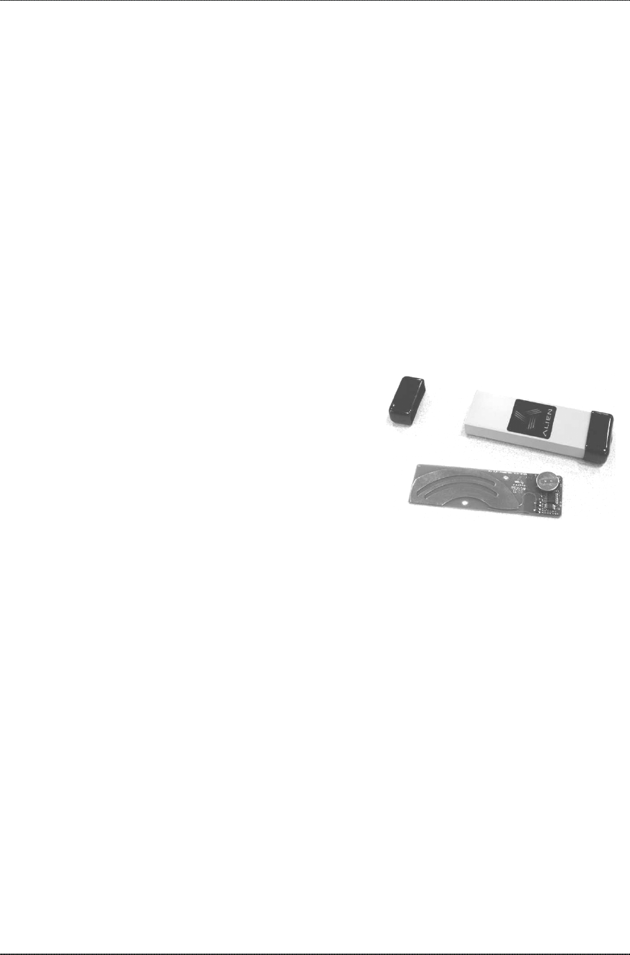
CLASS 1 EMULATOR TAG
If you are involved in testing the
AIDC specs or related applications,
you may be using the Alien Class 1
emulator tag, which, as described
earlier, is a modified version of the
Alien long-range data tag whose
range, data capacity and processing capabilities have been limited or
disabled to mimic the Class 1 tag performance.
Physical configuration of both the Alien
Class 1 emulator and long-range data tag.
LONG-RANGE DATA TAG
As referenced on the “RFID and ePC Tag Classes” table, the Alien long-
range data tag is similar to the Class 3, ePCdata+ tag. When the other tag
classes have been implemented, this tag will represent an upgrade in both
memory and range from the standard Class 3 ePCdata tag.
For the initial deployment of the Nanoscanner reader, this tag may be used
effectively for numerous commercial applications including fleet
management, automatic toll collection and an equipment tracking.
Requirements
In order to fully interface with the Nanoscanner reader you will need the
following:
PC running Windows 98 or higher, with CD-ROM drive (for demo system
software) and one available RS-232 serial port.
CHAPTER 3 INSTALLATION AND OPERATION
Standard 120 VAC power.
Host software (either Alien’s demo software or your own custom
software). Refer to the Nanoscanner Developer’s Guide for reader-host
protocols.
Tags (AIDC Class 1 compliant or Alien long-range data tags)
Standard power cord (desired length) with grounded, 3-pronged plugs
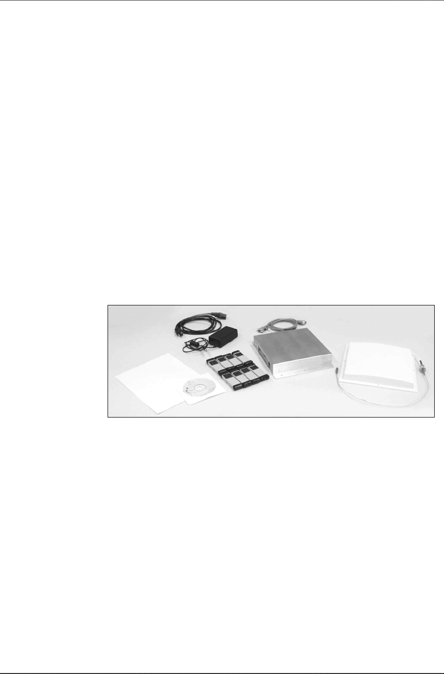
Receiving the Nanoscanner
Your Nanoscanner reader will be shipped with the items listed below. Please
verify the contents of your received shipment before assembling.
• Nanoscanner reader
• Antenna with coaxial cable
• RS-232 reader-to-PC cable
• Reader power supply and cables (two sections: one attached, one
detached)
• Nanoscanner Reader User Guide
Power supply & cables
Reader & RS-232 cable
Antenna w/cable
User guide
Sample tags*
Demo software CD*
Components of the Nanoscanner Reader Demo System
*If you have purchased a Nanoscanner Reader Demo System you will also
receive:
• Demo system software CD
• Assortment of tags
• Nanoscanner Reader Demo System User Guide
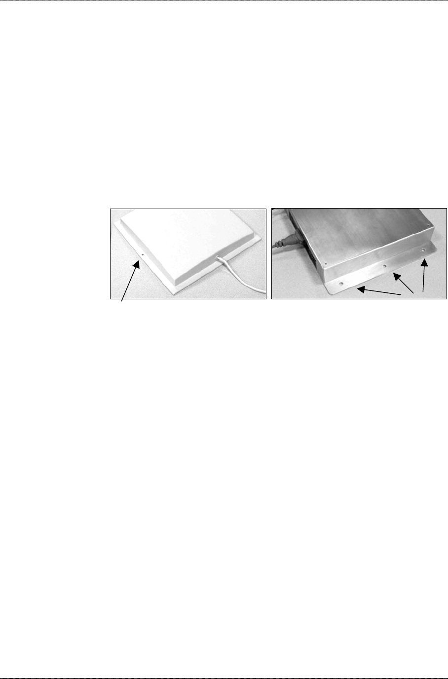
Reader Features
The Nanoscanner reader contains only two types of external user interface:
connector ports and LEDs. One panel contains I/O connectors and LEDs.
The opposite panel contains the antenna ports
I/O PANEL
The I/O panel (shown below) contains the following features:
• Power connector
NANOSCANNER READER USER GUIDE • DOC # 8101001-000A 19
© 2002 Alien Technology™
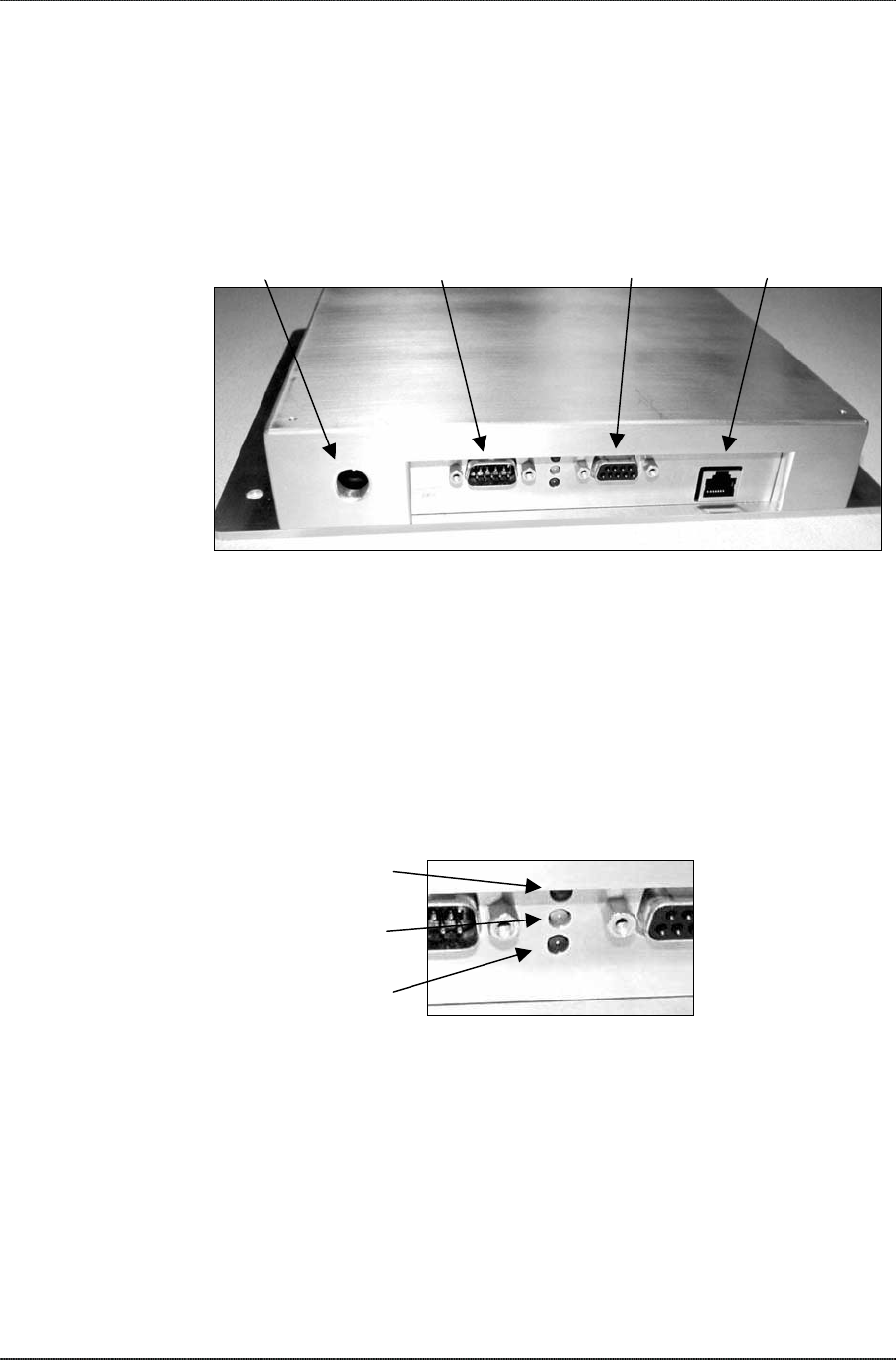
CHAPTER 3 INSTALLATION AND OPERATION
• 9-pin D male I/O port
• 3 LEDs (Power/red, Sniff/yellow, Lock/green)
• 9-pin D female RS-232 serial port
• LAN TCP/IP port
PowerI/O port (male) RS-232 (female) LAN TCP/IP port
Reader I/O panel
READER LEDS
The LEDs provide external indication of three conditions:
• Power (red). Indicates power is applied to the reader.
• Sniff (yellow). Indicates tag signal has been detected, though it may not
yet be strong enough to complete a transaction.
• Lock (green). Indicates a tag has been read.
Red = Power
Yellow = Sniff
Green = Lock
NANOSCANNER READER USER GUIDE • DOC # 8101001-000A 20
© 2002 Alien Technology™
CHAPTER 3 INSTALLATION AND OPERATION
ANTENNA PANEL
The antenna panel (opposite the reader’s I/O panel) contains two coax
antenna connector ports as shown below. These are reverse-threaded
connectors.
Reader antenna ports
CAUTION: If only one antenna is being used, the 50 ohm terminator cap
must remain attached to the unused port on the left to prevent possible
transmitter damage.
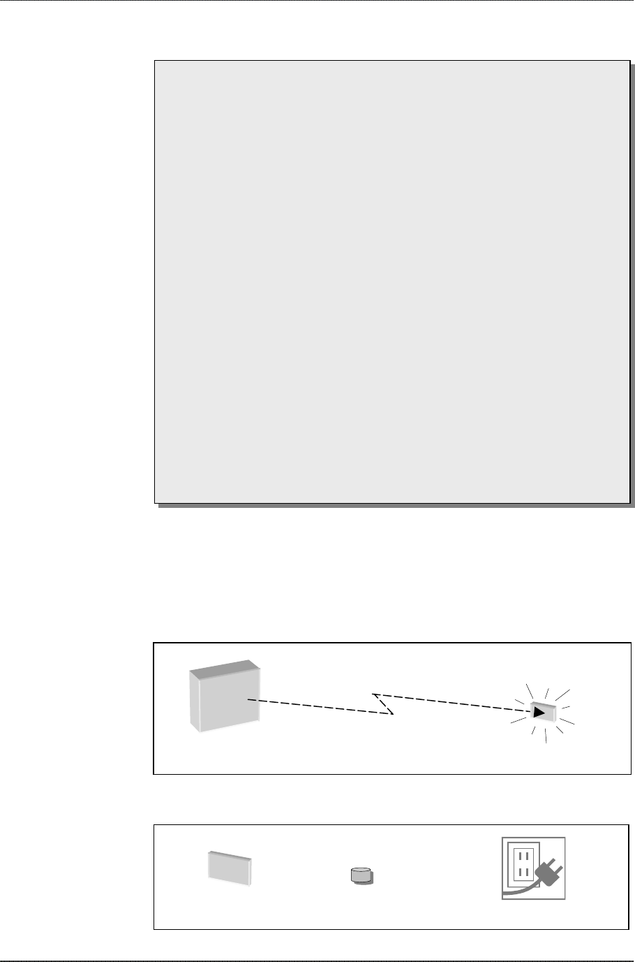
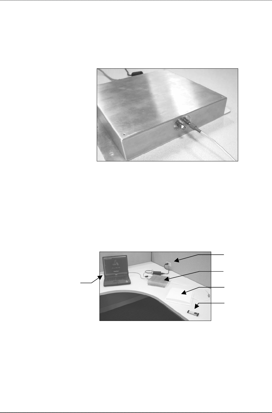
System Assembly and Bench Test
Assembling the Nanoscanner reader system is very easy. We recommend
you set up the system and verify its operation in a bench test configuration
(shown below) before installing it in a live application.
Two 120 VAC wall
outlets
Nanoscanner reader
PC Antenna
Tag
Typical reader system benchtest set-up.
BenchTest Connections
1. Situate the PC on a tabletop. Ensure the following conditions:
• Two standard 120 VAC outlets are available nearby (one for reader,
one for PC if needed).
• Sufficient space is available on the tabletop for the PC, reader and
antenna.
NANOSCANNER READER USER GUIDE • DOC # 8101001-000A 21
© 2002 Alien Technology™
CHAPTER 3 INSTALLATION AND OPERATION
Reader I/O panel
To antenna
Antenna ports (2)
To power supply &
120VAC wall outlet
RS-232 to PC
2. Connect the RS-232 cable to the reader.
• Align the male cable connector so that its shape and pins match the
shape and holes of the female DB-9 serial port.
• Push the aligned connector into the port.
• Finger-tighten the screws to secure the cable/connector to the
reader.
3. Connect the RS-232 cable to the serial port on the PC.
Power supply
connector
RS-232 serial
connector
To power supply To PC
4. Connect the power supply to the reader.
• Using the thin cable attached to power supply, push the connector
into the port until it is securely seated.
NANOSCANNER READER USER GUIDE • DOC # 8101001-000A 22
© 2002 Alien Technology™
CHAPTER 3 INSTALLATION AND OPERATION
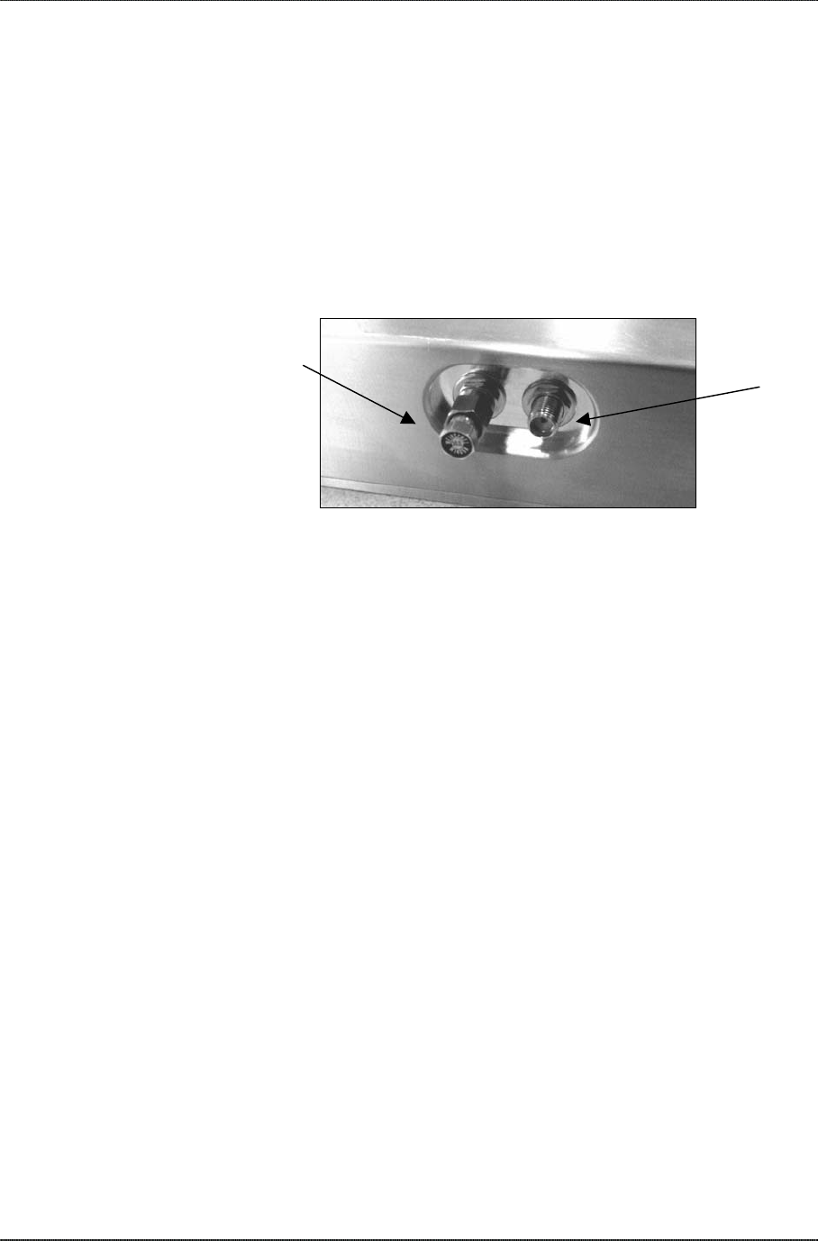
5. Connect the coaxial cable to antenna port 0.
Caution: For single antenna applications, you must use port 0, keeping
the 50 ohm terminator cap on port 1 to prevent transmitter damage.
• Antenna port 0 is on the right if viewing reader with flange side down.
• Align the coax cable’s center pin and push into the port
• Screw the fitting from the cable end onto the reader connector
counterclockwise until finger tight to secure the cable to the reader.
Antenna port 1 Antenna port 0
Reader antenna connector ports, showing unused
port (port 1) on the left with terminator cap in place.
• If using two antennas, unscrew the 50 ohm terminator cap from the
second port.
• Stow the cap in a convenient location for future use as these are
expensive items.
• Connect the second antenna to the port and tighten fitting
(counterclockwise)
6. Plug power cord into power supply.
• Use the female end of a standard 3-pronged power cord.
7. Plug the power supply cable into the wall outlet and verify power.
• The red LED will be illuminated when power is on.
8. Plug in the PC (if necessary) and turn it on.
• If the PC is a laptop operating on battery power, it is not necessary to
plug it into the wall outlet.
10. Launch the desired host software application.
• You may use Alien’s Nanoscanner demo system software or custom
software developed per the reader-host protocol (see Chapter 3) for
your specific application.
You are now ready to bench test the system.
NANOSCANNER READER USER GUIDE • DOC # 8101001-000A 23
© 2002 Alien Technology™

CHAPTER 3 INSTALLATION AND OPERATION
Bench Test Procedure
1. Access an operational mode suitable for bench testing.
• Select a mode that will allow multiple consecutive reads of a single
tag.
• Refer to the applicable software application user guide for specific
instructions.
2. Position the reader to you can see the LEDs.
• You may also want to position the PC so you can view the monitor
simultaneously for later tests.
3. Move a tag slowly into the antenna’s range.
• Begin with the tag well outside the expected range (~15-20 ft) and
move it toward the antenna while observing the LEDs.
4. Verify the Sniff LED illuminates when the tag approaches the read
window.
• Sniff is the yellow LED.
5. Verify the Lock LED illuminates when the tag is inside the read
window.
• Lock is the green LED.
6. Verify the host receives the tag data.
• Refer to indications specified in applicable user guide to verify the
tag was read successfully.
7. If bench test conditions are verified, proceed to installation.
NOTE: If all conditions appear to be operational but system fails to read tags,
disconnect system power and reapply power to perform a hard reset.
NANOSCANNER READER USER GUIDE • DOC # 8101001-000A 24
© 2002 Alien Technology™
CHAPTER 3 INSTALLATION AND OPERATION
System Design
The following Installation section provides basic guidance for configuring
components in your RFID system. We recommend you refer to the
Nanoscanner Reader Developer’s Guide for detailed system design
information before permanently mounting your equipment.
Installation
Installation involves all the same connection steps required for bench test.
However, instead of situating equipment on a tabletop, the reader and
antenna and their accessories will mounted in your application environment.
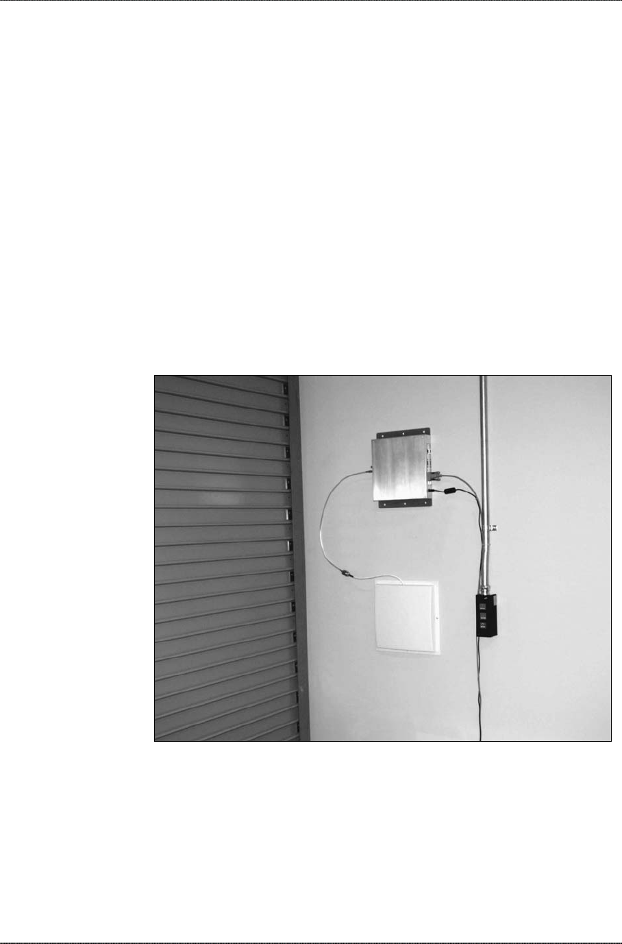
The photo below shows a reader with single antenna side-mounted at a
loading dock door for a portal application. This configuration may be used to
automatically identify tagged objects moving in and out of this door. Those
tagged objects may be pallets and cases on pallets, crates, equipment and
vehicles, or personnel.
Nanoscanner system configured for a single-antenna portal application. Shown
here at a loading dock.
A second (optional) antenna may be mounted on the opposite side of the
portal to better capture tags in a less than optimal position relative to the first
antenna (for example, tagged cases on the opposite side of a pallet).
Requirements
Before installing your Nanoscanner reader system you will need the
following:
NANOSCANNER READER USER GUIDE • DOC # 8101001-000A 25
© 2002 Alien Technology™
CHAPTER 3 INSTALLATION AND OPERATION
PC running Windows 98 or higher, with CD-ROM drive (for demo system
software) and one available RS-232 serial port
Standard 120 VAC power for the reader location and PC location
Host software
(Optional) second antenna (if desired for additional coverage)
Any additional RS-232 cables or connectorized antenna coax cables
needed to accommodate routing requirements
Standard grounded, three-pronged power cord of desired length
Mounting hardware suitable for the surface to which equipment is to be
attached (e.g., wood screws, moly-bolts, brackets, etc.)
Three mounting holes on either reader flange.
Antenna mounting holes
Installation Procedure
1. Select mounting position for antenna(s).
CAUTION: Reader antennas should be positioned so that personnel in
the area for prolonged periods may safely remain at least 23 cm (9 in) in
an uncontrolled environment from the antenna’s surface. See FCC OET
Bulletin 56 “Hazards of radio frequency and electromagnetic fields” and
Bulletin 65 “Human exposure to radio frequency electromagnetic fields.”
• Mount the antenna(s) at the periphery of the desired read window
(either overhead or at the side), so that the position of the most
distant tag passing through the window is no farther from the
antenna than the maximum range specified for your system design.
• Position the antenna(s) at a height approximately midway between
the highest and lowest expected tag position. (For example, a pallet
tag may be the lowest tag position to be read, while the top-most
case on a fully stacked pallet may represent your highest tag
position.)
• If you are using two antennas, mount the second antenna in a mirror-
image of the first antenna’s position, unless otherwise indicated in
your system design specification.
2. Select mounting position for reader.
• Reader should be positioned close enough to the antenna to
accommodate the cable length without putting strain on the
connectors.
• Be sure power is available to the selected reader location.
NANOSCANNER READER USER GUIDE • DOC # 8101001-000A 26
© 2002 Alien Technology™

CHAPTER 3 INSTALLATION AND OPERATION
3. Select location for host PC.
• Situate the host PC within 50 ft of the reader in a safe location away
from vehicular and foot traffic.
4. Install reader.
• Secure the reader through the three mounting holes on either flange
to its mounting location (wall, post, mounting bracket) using
appropriate hardware.
• If desired, position the reader so that the LEDs are easily observed.
5. Install antennas.
• Secure each antenna through the mounting holes on either flange to
its mounting location using appropriate hardware.
6. Connect antennas to reader.
• Route coax cables from antennas to reader according to your system
design specifications and secure them properly.
• Align the connector for each cable with the reader antenna port,
push into the port, and finger-tighten screw fitting.
7. Connect reader power.
• Push the power supply connector into the reader port.
• Plug the female end of the power cord into the power supply.
• Plug the male end of the power cord into the 120 VAC outlet.
8. Connect reader to host PC.
• Align the RS-232 connector with the corresponding serial port on the
reader and push the connector onto the pins. Finger-tighten the
screws to secure the cable to the reader.
• Align and connect the other end of the RS-232 with the serial port on
the PC.
9. Connect power to the PC.
NANOSCANNER READER USER GUIDE • DOC # 8101001-000A 27
© 2002 Alien Technology™

CHAPTER 3 INSTALLATION AND OPERATION
System Operation
Because the Nanoscanner reader is operated autonomously according to
programming from the host, there is little for the user to do in terms of direct
operation of the reader.
SOFTWARE DEVELOPERS
If you are a software developer, please refer to the next chapter, “Reader-
Host Protocol,” for information relevant to creating software to enable reader-
host communications and reader operation tailored to the desired application.
SYSTEM USERS
If you are a system user, please refer to your host software user guide for
information regarding system and software operations.
NANOSCANNER READER USER GUIDE • DOC # 8101001-000A 28
© 2002 Alien Technology™

CHAPTER 4 READER-ENTERPRISE PROTOCOL
CHAPTER 4
ReaderEnterprise Protocol
Overview
The Reader<->Enterprise protocol is a text-based communications protocol
for configuring and operating the Alien RFID Type I Reader for Enterprise
Systems connectivity.
Document Specifications
Nanoscanner Reader<->Enterprise Protocol
Revision Date June 24, 2002
Christopher I. Parkinson Prepared By
John M. Price
NANOSCANNER READER USER GUIDE • DOC # 8101001-000A 29
© 2002 Alien Technology™
CHAPTER 4 READER-ENTERPRISE PROTOCOL
Introduction
This document describes the programming interface that links the Alien RFID
Type I Reader to the outside world.
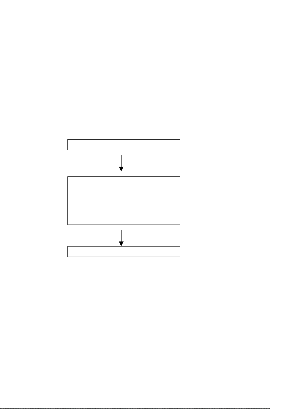
Reader Tag List
During normal operation of the reader, the device maintains an internal list of
the tags that are active. Active tags are the ones read by the reader at least
once within a predefined time period. Any new tags presented to the reader
are added to this list, and any tags that have not been seen for a while are
removed from the list. At any time a programmatic call can be made to the
reader to retrieve this list of tags.
New tags detected are added to the
active list.
80 00 01 00 88 20 FF A4
80 00 01 00 88 20 3F 02
80 00 04 00 02 32 3F 06
80 20 01 50 20 57 3F 12
80 00 02 00 80 20 3F 16
80 01 02 DE 34 FF 3F 17
Reader Tag List.
All tags listed are active.
NANOSCANNER READER USER GUIDE • DOC # 8101001-000A 30
© 2002 Alien Technology™
Persist Time
The persist time defines the duration between the time a tag was last read
and the time it is removed from the Reader Tag List. Setting this value to a
small time (~1 second) will cause the Reader Tag List to contain only what
the Reader has seen in the last second, i.e., a fair representation of what the
Reader sees at any one time. Setting the persist time to a long duration
allows a history of tags to be built up. For example, setting the persist time to
1 hour allows a list to be built up detailing all the tags read over the last hour.
Tags not read for a while are removed
from the list.
80 00 01 00 88 20 3F 09
Figure 1 – The Reader always has a concept of “what’s out there”, internally represented
by the Reader Tag List

CHAPTER 4 READER-ENTERPRISE PROTOCOL
Communication Protocol
Overview
Commands can be issued to the Reader in one of three ways:
• Serial Communication
• Network Communication
• Web Based Interaction
Serial Communication
Commands can be issued to the Reader using a direct Serial connection
from a computer to the Reader. The following settings are required for the
Serial communication:
Baud Rate : 115200
Data Bits : 8
Stop Bits : 1
Parity : None
Flow Control: None
Network Communication
Commands can be issued to the Reader over the Internet or Intranet. The
Reader is equipped with a standard Ethernet port allowing it to be physically
connected to a network. By default the Reader will use DHCP to wake up
and join a network. If DHCP is not available on the network, the Reader can
be network configured via Serial communication.
By default the Reader will listen to incoming commands over port 23, the
standard Telnet port.
Web Based Communication
The Reader contains a built in Web-server that allows all aspects of the
Reader to be controlled and configured via web pages served up by the
Reader. This web server operates on the standard port 80 used by most web
servers.
NANOSCANNER READER USER GUIDE • DOC # 8101001-000A 31
© 2002 Alien Technology™

CHAPTER 4 READER-ENTERPRISE PROTOCOL
Commands Introduction
Overview
There are two distinct categories of Reader<->Enterprise command: those
that are instantiated by the Enterprise host (Action commands), and those
that instantiated by the Reader itself (Notify commands)
Action Commands
Action commands are instantiated by an Enterprise system, which creates
and issues a command to the Reader. The Reader always responds to these
commands with an immediate reply. Action commands are used to configure
the reader, to operate it and to interrogate the tag lists.
Notify Commands
Notify commands are messages that are pushed out to the Enterprise by the
Reader in response to some action. Once the Enterprise system has
configured the Reader to push commands, the Reader is able to push tag
lists out in response to some action or some time elapsing. This allows the
Enterprise system to be notified on events, rather than constantly poll the
reader for changes.
Command Format
All commands between the Enterprise system and the Reader are human
readable ASCII text based messages. For example a command to set the
logical name of the Reader using the Set Reader Name command takes the
form:
Set ReaderName = My Alien Reader [CR][LF]
All commands to the reader are single line ASCII commands. These
commands are always terminated by a single carriage return / line feed
character pair [CR][LF], ascii code 0x0D followed by ascii 0x0A.
All replies from the reader are either single line or multiple line ASCII replies.
These replies are always terminated by a single carriage return / line feed
character pair [CR][LF] followed by a NULL character, ascii codes 0x0D,
0x0A, 0x00. Where a reply comprises multiple text lines, each line is
separated by a single carriage return / line feed character pair [CR][LF], ascii
code 0x0D followed by ascii 0x0A.
An example of a single line command / response is:
>Get ReaderName[CR][LF]
>ReaderName = Alien Reader[CR][LF][0]
An example of a multiple line command / response is:
>Get ReaderVersion[CR][LF]
>ReaderVersion = 1.0[CR][LF]
NANOSCANNER READER USER GUIDE • DOC # 8101001-000A 32
© 2002 Alien Technology™

CHAPTER 4 READER-ENTERPRISE PROTOCOL
FirmwareVersion = 1.0[CR][LF]
SoftwareVersion = 1.0[CR][LF][0]
Commands are case insensitive. i.e., set readername is equivalent to Set
ReaderName
Suppressing Command Prompts
By default all commands are set up for interactive use over a serial console
or telnet style interface. Consequently replies are always followed by a
command prompt indicating user input is required. Often this command
prompt is not required, especially when client software is written that
programmatically communicates with the reader. To account for these
applications, all command prompts can be suppressed by making the first
character of any command be an 0x1 character. For example,
Interactive Command Format:
Alien> get ReaderName[CR}[LF]
ReaderName = Alien Reader[CR][LF][0]
Alien>[CR][LF]
Non-Interactive Command Format:
[1]get ReaderName[CR][LF]
ReaderName = Alien Reader[CR][LF][0]
General Commands
Command Description
Get ReaderName
Set ReaderName
Allows an arbitrary name to be associated with
and retrieved from the Reader.
Get ReaderType Get a description of the Reader type
Get ReaderVersion Get the Reader software/hardware versions.
Get AntennaList
Set AntennaList
Get and Set the antenna port list the Reader
should use.
Get Time
Set Time
Get and Set the real time clock on the Reader.
Reboot Reboot the Reader.
NANOSCANNER READER USER GUIDE • DOC # 8101001-000A 33
© 2002 Alien Technology™

CHAPTER 4 READER-ENTERPRISE PROTOCOL
Network Configuration Commands
Command Description
Get DHCP
Set DHCP
Turn on or off the DHCP mode for the Reader. If DHCP is
on, the Reader will automatically configure itself for the
network on power-up.
Get IPAddress
Set IPAddress
Set and Get the network ID (IP Address) of the Reader. If
DHCP is enabled this will be set automatically.
Get Gateway
Set Gateway
Set and Get the network gateway. If DHCP is enabled this
will be set automatically.
Get Netmask
Set Netmask
Set and Get the subnet mask. If DHCP is enabled this will
be set automatically.
Get DNS
Set DNS
Set and Get the domain name server. If DHCP is enabled
this will be set automatically.
Get MailServer
Set MailServer
Set and Get an SMPT mail server. This is only required if
notification email messages are sent out.
Get HeartbeatPort
Set HeartbeatPort
The Reader periodically sends out heartbeat messages to
the network. The port over which this is done can
configured.
Get HeartbeatTime
Set HeartbeatTime
Set and Get the time interval, in seconds, between
successive heartbeats.
Get CommandPort
Set CommandPort
The Reader reacts to commands over the network only if
they are directed at a specific command port on the
Reader. This port can be configured using these
commands.
Enterprise Commands
Command Description
Get TagList Get the current list of active tags the from Reader.
Clear TagList Clear the list of active tags on the Reader.
Get PersistTime
Set PersistTime
Set and Get the Persist time
Get ReadTime
Set ReadTime
Set and Get the time interval between automated reads.
Get ReadTrigger
Set ReadTrigger
Set and Get the condition under which the automated
reads can be triggered.
NANOSCANNER READER USER GUIDE • DOC # 8101001-000A 34
© 2002 Alien Technology™

CHAPTER 4 READER-ENTERPRISE PROTOCOL
Notify Commands
Command Description
Get NotifyAddress
Set NotifyAddress
Get and Set the address to push tag lists to.
Set NotifyTime
Get NotifyTime
Get and Set the time interval for automatically pushing tag
lists.
Set NotifyTrigger
Get NotifyTrigger
Get and Set the trigger for pushing tag lists.
General Commands
GET READERNAME
SET READERNAME
Description: The reader can have an arbitrary text name associated with it to
aid identification in multiple-reader environments. This name can be retrieved
and changed at any time throughout Reader operation.
Example
Command
Response
>Get ReaderName
>ReaderName = My First Alien Reader
Command
Response
>Set ReaderName = My Second Alien Reader
>OK
GET READERTYPE
Description: The reader type text can be retrieved using this command. The
resulting text will be a single-line reply describing the model number of the
reader.
Example
Command
Response
>Get ReaderType
>ReaderType = Alien Passive Tag Reader Class 1
NANOSCANNER READER USER GUIDE • DOC # 8101001-000A 35
© 2002 Alien Technology™

CHAPTER 4 READER-ENTERPRISE PROTOCOL
GET READERVERSION
Description: The reader version text can be retrieved using this command.
The resulting text is a multi-line reply. Each line of the reply describes the
version number of a major reader component.
Example
Command
Response
>Get ReaderVersion
>Hardware Version = 1.0.02
Firmware Version = 1.0.01
Software Version = 1.1.22
SET ANTENNALIST
GET ANTENNALIST
Description: The reader can support the use of multiple antennae. This
command allows the user to select which antenna port(s) to use. If the
antenna is fixed, set this list to just one antenna number. Setting this list to
more than one antenna number will cause the reader to cycle through the list
on each successive tag read. Multiple antennae are specified by passing in a
comma separated list as the argument. An asterisk (*) by a number indicates
the current antenna in a list. The default value is 0. Currently antenna ports 0
and 1 are supported by this reader.
Example
Command
Response
>Get AntennaList
> AntennaList = 0*
>Get AntennaList
> AntennaList = 0, 1*
//Always use antenna 1
>Set AntennaList =1
>OK
//Cycle between antenna 0 and antenna 1
>Set AntennaList =0, 1
>OK
NANOSCANNER READER USER GUIDE • DOC # 8101001-000A 36
© 2002 Alien Technology™

CHAPTER 4 READER-ENTERPRISE PROTOCOL
GET TIME
GET TIME
Description: These commands allow the current time to be obtained or set
within the Reader. The primary purpose for having a real time clock is to
timestamp the tags in the taglist so that their discovery time can be recorded.
Times are always specified by the format YYYY/MM/DD hh:mm:ss. Changes
made with this command will require a reboot of the Reader to take effect.
Example
Command
Response
>Get Time
>Time = 2002/6/3 9:23:01
>Set Time = 2002/6/3 9:23:01
>OK
REBOOT
Description: The reboot command will immediately cause the Reader to
reboot itself.
Example
Command
Response
>Reboot
>OK : Rebooting Reader
Network Configuration Commands
GET DHCP
SET DHCP
Description: The reader supports automatic network configuration using the
widely available DHCP protocol. If DHCP is available at the Reader
installation site, this protocol can be switched on. If DHCP is not available or
not desired the use of this protocol can be switched off. Changes made with
this command will require a reboot of the Reader to take effect.
Valid command parameters are ON and OFF.
The default setting is ON.
Example
Command
Response
>Get DHCP
>DHCP=ON
Command
Response
>Set DHCP=OFF
>OK
NANOSCANNER READER USER GUIDE • DOC # 8101001-000A 37
© 2002 Alien Technology™

CHAPTER 4 READER-ENTERPRISE PROTOCOL
GET IPADDRESS
SET IPADDRESS
Description: If DHCP is not used for automatic configuration the Reader must
be manually configured for use on a network. The IPAddress command pair
allow the host’s IP Address to be assigned and interrogated. Changes made
with this command will require a reboot of the Reader to take effect.
Example
Command
Response
>Get IPAddress
>IPAddress =12.34.56.78
Command
Response
>Set IPAddress =34.55.33.12
>OK
GET GATEWAY
SET GATEWAY
Description: If DHCP is not used for automatic configuration the Reader must
be manually configured for use on a network. The gateway command pair
allow the network Gateway to be assigned and interrogated. Gateways must
be specified as an IP. Changes made with this command will require a reboot
of the Reader to take effect.
Example
Command
Response
>Get Gateway
>Gateway=34.56.78.90
Command
Response
>Set Gateway=12.56.23.01
>OK
GET NETMASK
SET NETMASK
Description: If DHCP is not used for automatic configuration the Reader must
be manually configured for use on a network. The subnet mask command
pair allow the subnet mask to be assigned and interrogated. Subnet masks
must be specified as an IP. Changes made with this command will require a
reboot of the Reader to take effect.
Example
Command
Response
>Get Netmask
>Netask=255.255.255.128
Command
Response
>Set Netmask=255.255.255.0
>OK
NANOSCANNER READER USER GUIDE • DOC # 8101001-000A 38
© 2002 Alien Technology™

CHAPTER 4 READER-ENTERPRISE PROTOCOL
GET DNS
SET DNS
Description: If DHCP is not used for automatic configuration the Reader must
be manually configured for use on a network. The DNS command pair allow
the DNS server location to be assigned and interrogated. DNS Servers must
be specified as an IP address. Changes made with this command will require
a reboot of the Reader to take effect.
Example
Command
Response
>Get DNS
>DNS=12.34.56.78
Command
Response
>Set DNS=45.224.124.34
>OK
GET MAILSERVER
SET MAILSERVER
Description: The MailServer command pair allow an SMTP mail server to be
defined. This mail server is used only when automatic notification is
configured (see Notify commands) and is set to use Mail as its delivery
method. Changes to this setting will take immediate effect.
Example
Command
Response
>Get MailServer
>MailServer=12.34.56.78
Command
Response
>Set MailServer=45.224.124.34
>OK
NANOSCANNER READER USER GUIDE • DOC # 8101001-000A 39
© 2002 Alien Technology™

CHAPTER 4 READER-ENTERPRISE PROTOCOL
GET HEARTBEATPORT
SET HEARTBEATPORT
Description: The Reader can be configured to periodically send out a
Heartbeat message to the network. This heartbeat takes the form of a single
UDP packet (Universal Datagram Packet) broadcast out to the entire subnet
that the Reader is configured for. The actual port number that this packet is
sent out to is configured using the HeartbeatPort command. Listening for this
heartbeat can be used to initially locate a Reader on a network and
subsequently make sure that the Reader is still alive.
Changes made with this command will take effect immediately.
The default setting for this command is 3988
The format of the UDP packet is a single text line containing three comma
separated fields terminated with a NULL character:
ReaderName, ReaderType, ReaderCommandPort
i.e., “Loading Dock Reader A, Alien Class I Reader, 4002[0]”
Example
Command
Response
>Get HeartbeatPort
>HeartbeatPort=3004
Command
Response
>Set HeartbeatPort=10002
>OK
GET HEARTBEATTIME
SET HEARTBEATTIME
Description: The Reader can be configured to periodically send out a
Heartbeat message to the network. This heartbeat takes the form of a single
UDP packet (Universal Datagram Packet) broadcast out to the entire subnet
that the Reader is configured for. The time interval between heartbeats can
be specified and interrogated using this command. All intervals are specified
in seconds. A setting of zero will suspend the output of any further
heartbeats.
Changes made with this command will take effect immediately.
The default setting for this command is 30 seconds.
Example
Command
Response
>Get HeartbeatTime
>HeartbeatTime=30
Command
Response
>Set HeartbeatTime=60
>OK
NANOSCANNER READER USER GUIDE • DOC # 8101001-000A 40
© 2002 Alien Technology™

CHAPTER 4 READER-ENTERPRISE PROTOCOL
GET COMMANDPORT
SET COMMANDPORT
Description: The Reader can be configured and operated over the network
using standard network sockets. The CommandPort settings are used to set
and get the exact port number used by the Reader for this network
connectivity.
Changes to this setting do not affect Serial communication and/or Web
communication with the Reader. Changes made with this command will take
effect immediately.
The default setting for this command is 23 (the standard Telnet port)
Example
Command
Response
>Get CommandPort
>CommandPort=23
Command
Response
>Set CommandPort=10004
>OK
Enterprise Commands
GET TAGLIST
Description: The get TagList command will retrieve the Reader’s current
internal tag list. The reply will be a multi-line command with each line listing
an active tag. If the tag list is empty, the message “(No Tags)” will be
returned
Each tag is listed in the format:
TagID, DiscoverTime, ReadCount, Antenna
• TagID is the unique ID code carried by the tag
• Discover Time is the time that the tag was first added to the current tag
list. It is formatted as YYYY/MM/DD hh:mm:ss (24 Hour clock)
• ReadCount is the number of time the tag has been read since Discover
Time
• Antenna is the antenna port that the tag was first read from.
Example
Command
Response
Get TagList
Tag: 00 02 00 30 A2 33 04, Discover: 2002/03/23 15:36:33,
Count: 4, Antenna: 0
Tag: 80 80 AA AB EC F0 00, Discover: 2002/03/22 12:26:01,
Count: 3, Antenna: 1
Command
Response
Get TagList
(No Tags)
NANOSCANNER READER USER GUIDE • DOC # 8101001-000A 41
© 2002 Alien Technology™

CHAPTER 4 READER-ENTERPRISE PROTOCOL
CLEAR TAGLIST
Description: The clear taglist command will cause the Reader to immediately
clear out its internal tag list.
Example
Command
Response
>Clear TagList
>OK
GET PERSISTTIME
SET PERSISTTIME
Description: The persist time is used by the Reader to build up its internal list
of active tags. Persist times are specified in seconds. Setting the persist time
to a positive number (0-n) will effect an persist time of the desired number of
seconds (a zero persist time will guarantee an empty tag list). Setting the
persist time to a negative number (-1) will effect an infinite persist time. I.e.,
any tags read will continually be added to the tag list.
The maximum number of tags that can be stored in the tag list is 5000. Once
this tag limit is reached, newer tags will replace the oldest ones in the list.
Changes made with this command will take effect immediately.
The default setting is 10 seconds.
Example
Command
Response
>Get PersistTime
>PersistTime=10
Command
Response
>Set PersistTime=300
>OK
NANOSCANNER READER USER GUIDE • DOC # 8101001-000A 42
© 2002 Alien Technology™

CHAPTER 4 READER-ENTERPRISE PROTOCOL
GET READTIME
SET READTIME
Description: The read time specifies when and for how long the Reader
attempts to read tags. The read time is set using two parameters, the sleep
time followed by the read duration. Both parameters are specified in
seconds. When set, the reader will repeat a cycle of sleeping for the
specified sleep time, then waking up and reading for the specified read
duration and then sleeping again. If the sleep time is set to zero or a negative
number, the reader will remain constantly on. If the read duration is set to
zero or a negative number the reader is switched off. If both are set to zero
the reader will be switched off.
Changes made with this command will take effect immediately.
The default setting is always reading i.e., 0, 1
Example
Command
Response
>Get ReadTime
>ReadTime=3000, 6000
Command
Response
>Set ReadTime=20, 10
>OK
GET READTRIGGER
SET READTRIGGER
Description: The read trigger defines under what conditions, other than timed
reads, a read is made.
Reads can be triggered under any of the following conditions, which can be
added together for multiple trigger conditions. Each trigger condition is a
trigger mode followed by a trigger parameter and a number of seconds to
keep reading for after the trigger has been activated. Multiple trigger
conditions are semicolon (;) separated options in the text line.
Changes made with this command will take effect immediately.
Trigger Name Meaning
ON_EXTERNAL_IO Trigger a read if External IO is triggered. This parameter is
followed immediately by a number indicating the External
IO Trigger number to use.
Example
Command
Response
>Get ReadTrigger
>ReadTrigger= ON_EXTERNAL_IO, 1, 20
Command
Response
>Set ReadTrigger= ON_EXTERNAL_IO, 1, 30
>OK
NANOSCANNER READER USER GUIDE • DOC # 8101001-000A 43
© 2002 Alien Technology™

CHAPTER 4 READER-ENTERPRISE PROTOCOL
Notify Commands
GET NOTIFYADDRESS
SET NOTIFYADDRESS
Description: The notify address command pair specify where messages
should be sent to when they arise and how they should be sent. The form of
the address determines the method of delivery. Currently there are 3 delivery
methods supported:
NotifyAddress Description
blank Do not use automatic notification.
user@domain.com
Send a message via Email to the address specified. The
address is specified in standard email form i.e.,
user@domain.com
Note that the MailServer parameter must be configured for
this to work (see Network Commands)
hostname:port Send a message to a specified port on a networked
machine. The address takes the form hostname:port. For
example “123.01.02.98:3450” or
“listener.alientechnology.com:10002”
serial Send a message to the serial connection. The word
“serial” is used as the address. The word is not case
sensitive.
Changes made with this command will take effect immediately.
By default setting is OFF.
Example
Command
Response
>Get NotifyAddress
>NotifyAddress=10.1.0.12:4000
Command
Response
>Set NotifyAddress=user@msn.com
>OK
NANOSCANNER READER USER GUIDE • DOC # 8101001-000A 44
© 2002 Alien Technology™

CHAPTER 4 READER-ENTERPRISE PROTOCOL
GET NOTIFYTIME
SET NOTIFYTIME
Description: The notify time defines the time interval for automatic tag list
pushing to a listening machine. The time is specified in seconds. If set to
zero or a negative number the time-based automatic notification is disabled.
When set to a positive number of seconds, the complete tag list will be
pushed out each period.
Changes made with this command will take effect immediately.
Example
Command
Response
>Get NotifyTime
>NotifyTime=30
Command
Response
>Set NotifyTime=30
>OK
GET NOTIFYTRIGGER
SET NOTIFYTRIGGER
Description: The notify trigger defines under what conditions a message is
pushed out to any listener. Notify commands can be triggered under any of
the following conditions.
Trigger Name Meaning
ON_ADD
Push message when new tag is read and added to the
TagList
ON_REMOVE Push message when a tag is removed from the TagList
ON_CHANGE Push message when a tag is either added or removed
from the TagList
ON_EXTERNAL_IO Push message when a read is triggered via the external IO
pins
Changes made with this command will take effect immediately.
Example
Command
Response
>Get NotifyTrigger
>NotifyTrigger= ON_REMOVE
Command
Response
>Set NotifyTrigger=ON_ADD
>OK
NANOSCANNER READER USER GUIDE • DOC # 8101001-000A 45
© 2002 Alien Technology™

CHAPTER 4 READER-ENTERPRISE PROTOCOL
NOTIFY MESSAGE FORMAT
When either the Notify Trigger is activated or the Notify Time has elapsed a
formatted message is sent to the listener specified by the Notify Address.
The format of this message is always a multi-line response of trigger reason
followed by a list of tags.
Notify Message Format:
#Alien RFID Reader Auto Notification
Reason
tagID, discoverTime, readCount, antenna
tagID, discoverTime, readCount, antenna
The following reasons are permissible
Trigger Name Meaning
ON_TIME Message is pushed because NotifyTime seconds have
elapsed and NotifyTime seconds is greater than zero.
TagList to follow is complete taglist from Reader.
ON_ADD
Message is pushed because a Tag was added to the
Reader tag list, and ON_ADD was set in the NotifyTrigger
command. TagList to follow is list of added tags only.
ON_REMOVE Message is pushed because a Tag was removed from the
Reader tag list, and ON_REMOVE was set in the
NotifyTrigger command. TagList to follow is list of removed
tags only.
ON_CHANGE Message is pushed because a Tag was either added to
the Reader tag list or removed, and ON_CHANGE was set
in the NotifyTrigger command. TagList to follow is
complete taglist from Reader.
ON_EXTERNAL_IO Message is pushed because an external IO pin was
triggered and ON_EXTERNAL_IO was set in the
NotifyTrigger command. TagList to follow is complete
taglist from Reader
NANOSCANNER READER USER GUIDE • DOC # 8101001-000A 46
© 2002 Alien Technology™