Alliance Laundry Systems F232157R7 Users Manual Programming For Washer Extractors
F232157R7 F232157
f232157r7 2ac16b75-3126-40e1-9d06-2195f33f017a Alliance Laundry Systems Washer F232157R7 User Guide |
2015-02-05
: Alliance-Laundry-Systems Alliance-Laundry-Systems-F232157R7-Users-Manual-506555 alliance-laundry-systems-f232157r7-users-manual-506555 alliance-laundry-systems pdf
Open the PDF directly: View PDF ![]() .
.
Page Count: 36
Programming
www.comlaundry.com
Part No. F232157R7
August 2009
Keep These Instructions for Future Reference.
(If this machine changes ownership, this manual must accompany machine.)
Washer-Extractors
Cabinet Hardmount
B-Series Microcomputer for Coin Models
2 Speed and Variable-Speed
Refer to Page 7 for Model Identification
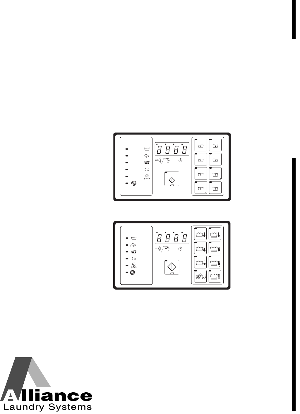
CHM
4
WASH
ADD
BLEACH
RINSE
SPIN
DOOR
NORMAL
NORMAL
QUICK AS QUICK WASH
HEAVY SOIL
DELICATE
RM RESS
PERM PRESS
HOT
WARM
HOT
HOT
WARM
COLD
WARM
COLD
START
PE P
WH
DOMESTIC MODELS
60C 60C
40C 40C
95C 95C
<
<
30C
CHM488R
INTERNATIONAL MODELS
CHM488R
CHM482R
© Copyright, Alliance Laundry Systems LLC – DO NOT COPY or TRANSMIT
© Copyright 2009, Alliance Laundry Systems LLC
All rights reserved. No part of the contents of this book may be reproduced or transmitted in any form or by any
means without the expressed written consent of the publisher.
F232157 1
Table of
Contents
Safety Information.............................................................................. 3
Explanation of Safety Messages........................................................... 3
Important Safety Instructions ............................................................... 3
Safety Decals ........................................................................................ 5
Operator Safety..................................................................................... 6
Introduction......................................................................................... 7
Model Identification......................................................................... 7
Nameplate Location.............................................................................. 8
Replacement Parts ................................................................................ 8
Customer Service.................................................................................. 8
Electronic Control Unit......................................................................... 9
Control Output Fuse Board................................................................... 9
Summary of Control Outputs and Inputs.............................................. 9
Outputs............................................................................................. 9
Inputs................................................................................................ 9
Control Voltage................................................................................ 9
Harnessing........................................................................................ 9
Communications ................................................................................... 10
Central Pay System .......................................................................... 10
Third Party Card Reader .................................................................. 10
Programming ...................................................................................... 12
Entering Program Mode ....................................................................... 12
Determining Firmware ID Code........................................................... 12
Programming Vend Price
(For Models with Firmware ID Code “C2HL” and “CuHL”)............ 13
Setup Mode ...................................................................................... 13
Cycle and Error Count .......................................................................... 14
Cycle and Error Count addition............................................................ 14
Programming Cycle Segments......................................................... 14
Programming Vend Price
(For Earlier Models)........................................................................... 15
Setup Mode ...................................................................................... 15
Cycle and Error Count .......................................................................... 16
Programming Cycle Segments......................................................... 16
Options for Each Segment.................................................................... 18
To Edit an Entire Wash Cycle Formula................................................ 24
Wash 1 – Wash 4 ............................................................................. 24
Rinse 1 – Rinse 4 ............................................................................. 25
Abnormal Conditions............................................................................ 26
Door Will Not Lock ......................................................................... 26
Door Open During Operation .......................................................... 26
Excessive Fill Time.......................................................................... 26
Out-of-Balance................................................................................. 26
Drain Error (For Models With Firmware ID Code “C2HL” and
“CuHL”) ......................................................................................... 27
Clogged Filter (All C80 and C60 X Voltage ONLY Models)......... 27
Door Will Not Unlock ..................................................................... 27
On Board Battery Problem............................................................... 27
© Copyright, Alliance Laundry Systems LLC – DO NOT COPY or TRANSMIT
2F232157
Temperature Probe Malfunction ...................................................... 27
Rapid Advance (For Models With Firmware ID Code “C2HL” and
“CuHL”) ............................................................................................. 27
Enabling Rapid Advance ................................................................. 27
How to Rapid Advance During All Steps
(Except First Fill Step)..................................................................... 27
How to Rapid Advance (During First Fill Step).............................. 27
Temporary Free Mode .......................................................................... 28
Test Cycle ............................................................................................. 28
Permanent Factory Diagnostic Test Cycle ........................................... 29
Cycle Charts.......................................................................................... 31

© Copyright, Alliance Laundry Systems LLC – DO NOT COPY or TRANSMIT 3
F232157
Safety Information
Explanation of Safety Messages
Precautionary statements (“DANGER,” “WARNING,”
and “CAUTION”), followed by specific instructions,
are found in this manual and on machine decals. These
precautions are intended for the personal safety of the
operator, user, servicer, and those maintaining the
machine.
Additional precautionary statements (“IMPORTANT”
and “NOTE”) are followed by specific instructions.
IMPORTANT: The word “IMPORTANT” is used
to inform the reader of specific procedures where
minor machine damage will occur if the procedure
is not followed.
IMPORTANT: The word “NOTE” is used to
communicate installation, operation, maintenance
or servicing information that is important but not
hazard related.
Important Safety Instructions
1. Read all instructions before using the washer.
2. Refer to the GROUNDING INSTRUCTIONS in
the INSTALLATION manual for the proper
grounding of the washer.
3. Do not wash textiles that have been previously
cleaned in, washed in, soaked in, or spotted with
gasoline, kerosene, waxes, cooking oils, dry-
cleaning solvents, or other flammable or
explosive substances as they give off vapors that
could ignite or explode.
4. Do not add gasoline, dry-cleaning solvents, or
other flammable or explosive substances to the
wash water. These substances give off vapors that
could ignite or explode.
5. Under certain conditions, hydrogen gas may be
produced in a hot water system that has not been
used for two weeks or more. HYDROGEN GAS
IS EXPLOSIVE. If the hot water system has not
been used for such a period, before using a
washing machine or combination washer-dryer,
turn on all hot water faucets and let the water
flow from each for several minutes. This will
release any accumulated hydrogen gas. The gas
is flammable; do not smoke or use an open flame
during this time.
6. Do not allow children to play on or in the washer.
Close supervision of children is necessary when
the washer is used near children. This is a safety
rule for all appliances.
7. Before the washer is removed from service or
discarded, remove the door to the washing
compartment.
8. Do not reach into the washer if the wash drum is
moving.
DANGER indicates the presence of a
hazard that will cause severe personal
injury, death, or substantial property
damage if the danger is ignored.
DANGER
WARNING indicates the presence of a
hazard that can cause severe personal
injury, death, or substantial property
damage if the warning is ignored.
WARNING
CAUTION indicates the presence of a
hazard that will or can cause minor
personal injury or property damage if the
caution is ignored.
CAUTION
To reduce the risk of fire, electric shock,
serious injury or death to persons when
using your washer, follow these basic
precautions:
W023
WARNING
© Copyright, Alliance Laundry Systems LLC – DO NOT COPY or TRANSMIT
Safety Information
F232157
4
9. Do not install or store the washer where it will be
exposed to water and/or weather.
10. Do not tamper with the controls.
11. Do not repair or replace any part of the washer, or
attempt any servicing unless specifically
recommended in the user-maintenance
instructions or in published user-repair
instructions that the user understands and has the
skills to carry out.
12. To reduce the risk of an electric shock or fire, DO
NOT use an extension cord or an adapter to
connect the washer to the electrical power
source.
13. Use washer only for its intended purpose,
washing textiles.
14. Never wash machine parts or automotive parts in
the machine. This could result in serious damage
to the basket.
15. ALWAYS disconnect the washer from electrical
supply before attempting any service. Disconnect
the power cord by grasping the plug, not the cord.
16. Install the washer according to the installation
instructions. All connections for water, drain,
electrical power and grounding must comply
with local codes and be made by licensed
personnel when required.
17. To reduce the risk of fire, textiles which have
traces of any flammable substances such as
vegetable oil, cooking oil, machine oil,
flammable chemicals, thinner, etc. or anything
containing wax or chemicals such as in mops and
cleaning cloths, must not be put into the washer.
These flammable substances may cause the
fabric to catch on fire by itself.
18. Do not use fabric softeners or products to
eliminate static unless recommended by the
manufacturer of the fabric softener or product.
19. Keep washer in good condition. Bumping or
dropping the washer can damage safety features.
If this occurs, have washer checked by a
qualified service person.
20. If the supply cord is damaged, it must be replaced
by a special cord or assembly available from the
manufacturer or its service agent.
21. Be sure water connections have a shut-off valve
and that fill hose connections are tight. CLOSE
the shut-off valves at the end of each wash day.
22. Loading door MUST BE CLOSED any time the
washer is to fill, tumble or spin. DO NOT bypass
the loading door switch by permitting the washer
to operate with the loading door open.
23. Always read and follow manufacturer’s
instructions on packages of laundry and cleaning
aids. Heed all warnings or precautions. To reduce
the risk of poisoning or chemical burns, keep
them out of the reach of children at all times
(preferably in a locked cabinet).
24. Always follow the fabric care instructions
supplied by the textile manufacturer.
25. Never operate the washer with any guards and/or
panels removed.
26. DO NOT operate the washer with missing or
broken parts.
27. DO NOT bypass any safety devices.
28. Failure to install, maintain, and/or operate this
washer according to the manufacturer’s
instructions may result in conditions which can
produce bodily injury and/or property damage.
NOTE: The WARNINGS and IMPORTANT
SAFETY INSTRUCTIONS appearing in this
manual are not meant to cover all possible
conditions and situations that may occur. Common
sense, caution and care must be exercised when
installing, maintaining, or operating the washer.
Any problems or conditions not understood should be
reported to the dealer, distributor, service agent or the
manufacturer.
© Copyright, Alliance Laundry Systems LLC – DO NOT COPY or TRANSMIT
Safety Information
5
F232157
IMPORTANT: Ensure that the recommended
clearances for inspection and maintenance
are provided. Never allow the inspection and
maintenance space to be blocked.
Safety Decals
Safety decals appear at crucial locations on the
machine. Failure to maintain legible safety decals
could result in injury to the operator or service
technician.
To provide personal safety and keep the machine in
proper working order, follow all maintenance and
safety procedures presented in this manual. If
questions regarding safety arise, contact the
manufacturer immediately.
Use manufacturer-authorized spare parts to avoid
safety hazards.
This machine must be installed, adjusted,
and serviced by qualified electrical
maintenance personnel familiar with the
construction and operation of this type of
machinery. They must also be familiar
with the potential hazards involved.
Failure to observe this warning may result
in personal injury and/or equipment
damage, and may void the warranty.
SW004
WARNING
Install the machine on a level floor of
sufficient strength. Failure to do so may
result in conditions which can produce
serious injury, death and/or property
damage.
W703
WARNING
Be careful around the open door,
particularly when loading from a level
below the door. Impact with door edges
can cause personal injury.
SW025
CAUTION
Never touch internal or external steam
pipes, connections, or components.
These surfaces can be extremely hot and
will cause severe burns. The steam must
be turned off and the pipe, connections,
and components allowed to cool before
the pipe can be touched.
SW014
WARNING

© Copyright, Alliance Laundry Systems LLC – DO NOT COPY or TRANSMIT
Safety Information
F232157
6
Operator Safety
To ensure the safety of machine operators, the
following maintenance checks must be performed
daily:
1. Prior to operating the machine, verify that all
warning signs are present and legible. Missing or
illegible signs must be replaced immediately.
Make certain that spares are available.
2. Check door interlock before starting operation of
the machine:
a. Attempt to start the machine with the door
open. The machine should not start with the
door open.
b. Close the door without locking it and attempt
to start the machine. The machine should not
start with the door unlocked.
c. Close and lock the door and start a cycle.
Attempt to open the door while the cycle is in
progress. The door should not open.
If the door lock and interlock are not functioning
properly, call a service technician.
3. Do not attempt to operate the machine if any of
the following conditions are present:
a. The door does not remain securely locked
during the entire cycle.
b. Excessively high water level is evident.
c. Machine is not connected to a properly
grounded circuit.
Do not bypass any safety devices in the machine.
NEVER insert hands or objects into
basket until it has completely stopped.
Doing so could result in serious injury.
SW012
WARNING
Never operate the machine with a
bypassed or disconnected balance
system. Operating the machine with
severe out-of-balance loads could result
in personal injury and serious equipment
damage.
SW039
WARNING

© Copyright, Alliance Laundry Systems LLC – DO NOT COPY or TRANSMIT 7
F232157
Introduction
Model Identification
Information in this manual is applicable
to these models:
HC20BC2 HC30BY2 HC60BXF SC20BX2 SC40BL2 SC60BYF
HC20BL2 HC40BC2 HC60BYF SC20BY2 SC40BX2 SC60BY2
HC20BX2 HC40BL2 HC60BY2 SC25BC2 SC40BY2 SC80BCV
HC20BY2 HC40BX2 HC80BCV SC25BL2 SC50BC2 SC80BLV
HC25BC2 HC40BY2 HC80BLV SC25BX2 SC50BY2 SC80BXV
HC25BL2 HC50BC2 HC80BXV SC25BY2 SC60BC2 SC80BYV
HC25BX2 HC50BY2 HC80BYV SC30BC2 SC60BCF SC125BCV
HC25BY2 HC60BC2 HC125BCV SC30BL2 SC60BL2 SC125BYV
HC30BC2 HC60BCF HC125BYV SC30BX2 SC60BLF
HC30BL2 HC60BLF SC20BC2 SC30BY2 SC60BX2
HC30BX2 HC60BX2 SC20BL2 SC40BC2 SC60BXF
© Copyright, Alliance Laundry Systems LLC – DO NOT COPY or TRANSMIT
Introduction
F232157
8
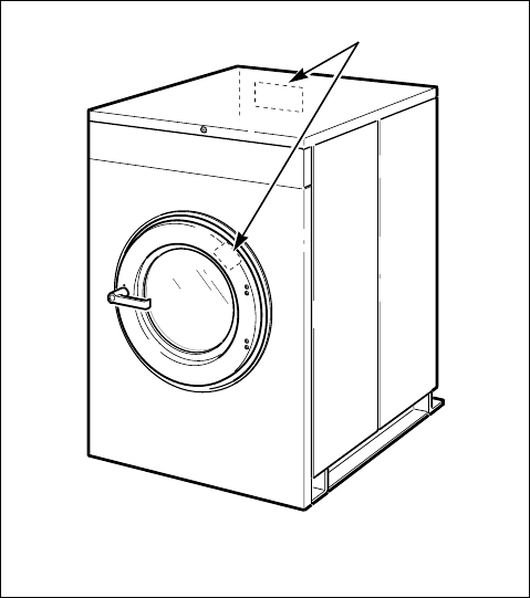
Nameplate Location
The nameplate is located at the rear of the machine and
inside door. Always provide the machine’s serial
number and model number when ordering parts or
when seeking technical assistance.
Figure 1
Replacement Parts
If literature or replacement parts are required, contact
the source from whom the machine was purchased or
contact Alliance Laundry Systems at (920) 748-3950
for the name and address of the nearest authorized
parts distributor.
Customer Service
For technical assistance, call (920) 748-3121
Ripon, Wisconsin.
CHM167R
1Nameplate
CHM167R
1
© Copyright, Alliance Laundry Systems LLC – DO NOT COPY or TRANSMIT
Introduction
9
F232157
Electronic Control Unit
The “B” electronic control is composed of the
electronic control unit and the control fuse board with
wiring harness. Only an authorized person should look
inside the control compartment. First TURN OFF
POWER, open lid and remove any cover present.
Make sure door lock circuit has fully discharged. The
door unlock capacitor can retain high electrical charge,
even when the machine’s electrical inputs are
disconnected, until it has discharged. Some machines
are equipped with an orange or red indicator light
facing upward in the control compartment. If this is
on, wait until light goes off (indicating when high
voltage in the door lock circuit has discharged). The
components are described below.
This portion of the control contains the “intelligence” –
the micro-controller and the miscellaneous components
on the printed circuit (PC) board. The board has a
metal cover, which MUST be in place at all times
during machine operation. Operation of the machine
without this cover installed will void the warranty.
The control unit monitors and responds to input, gives
information about the status of the washer and
monitors and responds to inputs from the user
interface (keypad). The control provides signals to the
control output unit, which in turn operates the
components that control the machine functions. This is
located behind the machine control panel.
Control Output Fuse Board
This portion of the control contains the power supply
for the control unit, and also the switching devices
which power the components in the machine, all of
which are on the output PC board. The switching
devices are controlled by the control unit, and are solid
state.
Summary of Control Outputs and
Inputs
Outputs
General outputs provide signals to operate the
following components.
1. Hot Fill Valve (HF)
2. Cold Fill Valve (CF)
3. Drain Valve (normally open) (DR)
4. Door Lock Solenoid Coil (DL)
5. Door Unlock Solenoid Coil (DU)
6. Supply 1 (detergent) (S1)
7. Supply 2 (bleach) (S2)
8. Supply 3 (sour/softener) (S3)
9. Optional 3rd (Extra) Fill Inlet (governed by the
configuration settings) (S4)
10. Optional Heat (HT)
11. *Prep for Card Reader or Central Pay (“machine
available signal”)
For standard models, the components for outputs
shown as “optional” will not be populated on the
output printed circuit board.
AC outputs are solid state outputs that operate either
120 Volt AC or 220 Volt AC (nominal voltage)
components, depending on the control voltage
configuration. Outputs are fused appropriately.
Inputs
1. Low Water Level
2. Medium Water Level
3. High Water Level
4. Door
5. Coin 1 Signal
6. Coin 2 Signal
7. *Prep for Card Reader or Central Pay (“start
pulse”)
* This allows machine to interface with the card reader or the
central pay system. “Start Pulse” originates from the reader/
central pay system, and this satisfies the programmed vend.
B control provides “Machine Available” signal to reader/
central pay when it is ready to accept payment. Refer to
Machine Electrical Schematic.
Control Voltage
The control power supply can be configured to operate
on 110 Volt AC nominal RMS input voltage
50/60 Hertz, OR 220 Volt AC nominal RMS input
voltage 50/60 Hertz.
Harnessing
Wiring harnesses are modular – harnesses common to
various configurations are similar, while those specific
to a certain configuration can be added. There are
harnesses for inputs to the control unit, for outputs
from the control power/output unit to the machine
components, and for the main incoming power to the
control power/output unit.

© Copyright, Alliance Laundry Systems LLC – DO NOT COPY or TRANSMIT
Introduction
F232157
10
Communications
Central Pay System
(Central Pay System Models Only)
The models are usually designated by the “Prep for
Central Pay” option. The model number will have an
“L” in the 6th digit (i.e. *C40BL2OU6001). Refer to
Nameplate Location. The control will accept a start
pulse from the central pay system and will give a
“machine available” signal.
* Denotes Brand
For detailed information on the Central Pay System
Communications, refer to the manufacturer.
Third Party Card Reader
(Card Reader Models Only)
The models are usually designated by the “Prep for
Card Reader” option. The model number will have a
“Y” in the 6th digit (i.e. *C40BY2OU6001). Refer to
Nameplate Location. The control will accept
communications with a Card Reader in order to
perform vending transactions when a card is inserted
to pay for cycles.
* Denotes Brand
For detailed information on the Card Reader
Communications, refer to the manufacturer.
© Copyright, Alliance Laundry Systems LLC – DO NOT COPY or TRANSMIT
Introduction
11
F232157
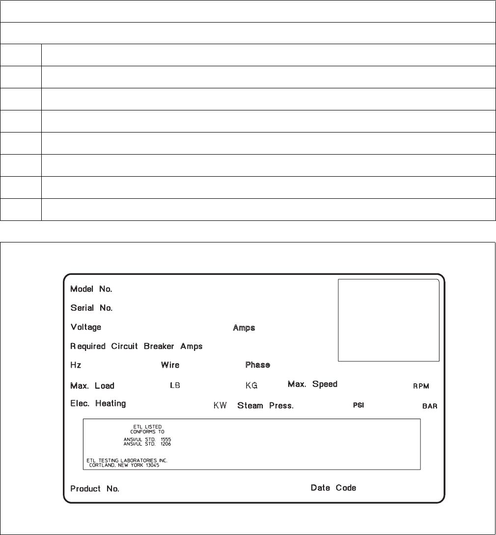
* Denotes Brand
Figure 2
Model Number Familiarization Guide
Sample Model Number: *C40BY2OU60001
*C Model Number Prefix
40 Washer-Extractor Capacity (pounds dry weight of laundry)
BType of Electrical Control
YActuation (Y = Prep for Card Reader)
2Washer-Extractor Speed Capability (2 = 2 speed)
OElectrical Characteristics
U6 Design Series
0001 Option Identification (varies from machine to machine)
CHM523R
CHM523R
*C40BY2OU60001
00000000000
500000
208 – 240
60 3 3
0
18
3
60
N/A N/A
470
7
EXAMPLE OF NAMEPLATE
© Copyright, Alliance Laundry Systems LLC – DO NOT COPY or TRANSMIT F232157
12
Programming
NOTE: The machines are factory programmed
with basic cycles to make the units operational
without programming at installation.
Entering Program Mode
1. Open machine lid.
2. Locate Program/Run switch on the computer
board. This is accessed through a cutout in the
metal control unit cover. This switch protrudes
from the rear of the electronic control unit cover.
3. Flip switch to the left (as seen from front of
machine) to enter PROGRAM Mode.
4. Display will show “0000” or temperature or
“tSFL” (depending on version of the control).
Determining Firmware ID Code
1. Turn on the main power source (circuit breaker or
cut-off switch on wall).
2. Display will show Firmware ID code (i.e.,
“C2dS” and “CvdS” etc…).
3. Record Firmware ID Code for future reference.
© Copyright, Alliance Laundry Systems LLC – DO NOT COPY or TRANSMIT
Programming
13
F232157
Programming Vend Price
(For Models with Firmware ID Code
“C2dS” and “CvdS”)
Setup Mode
NOTE: In SETUP Mode, certain machine
functions can be configured. The settings in this
mode are related to how the machine is equipped
from the factory. Usually, these would not be
changed in the field.
NOTE: Enter SETUP Mode through the
PROGRAM Mode. Refer to Entering Program
Mode.
1. Press (*) keypad. Display shows machine model
size (capacity). Displayed capacity must match
machine size. Press (∧) keypad to change the
capacity. (This should already be set correctly
from the factory, and normally should never need
to be changed).
2. Press START (Enter) keypad.
3. Display shows “FAr” or “CEL”.
NOTE: This option selects whether temperatures
display in degrees Fahrenheit (F) or Celsius (C), if
control is equipped with a temperature sensor.
Press the (∧) or (∨) keypad to change degrees
“FAr” or “CEL”.
4. Press START (Enter) keypad.
5. If model displays “HEAt” or “noHt”, change the
selection by pressing the (∧) or (∨) keypad. If
model displays “CArd” or “COIn”, skip to
step# 8.
6. Press START (Enter) keypad to continue to the
next step.
7. “EFIL” or “nEFL” will display in certain models.
“EFIL” means the capability to control an extra
fill valve with programmable water level (same
as regular fills) is enabled. Machine MUST be
equipped with the extra valve for this to work
properly. “nEFL” means the extra fill valve
option is disabled or not installed on machine.
NOTE: If neither message displays, the extra fill
capability is not present. If either message displays,
changing the selection is an option by pressing the
(∧) or (∨) keypad. Press START (Enter) keypad to
continue to the next option.
8. If model displays the message “CArd” or
“COIn”, change the selection by pressing the (∧)
or (∨) keypad.
9. Press START (Enter) keypad to continue to the
next selection.
NOTE: Select “COIn used by accessory pay
system. Contact the manufacturer of the accessory
pay system if not working properly
10. “bEEP” or “nobP” will display in certain models.
If “bEEP” is set, control will beep during Add
Bleach (Supply 2) and at end of cycle after
several seconds while displaying “dOnE”. If
“nobP” displays, control will NOT beep during
Add Bleach (Supply 2) or at end of cycle. This
does not affect the short beep when a keypad is
pressed or a coin is inserted and it does not affect
the beep during an alarm. Press the (∧) or (∨)
keypad to change “bEEP”/“nobP” selection.
11. Press START (Enter) keypad to continue to next
step.
12. “PtIn” means the control will display remaining
time in a cycle without fill and drain times.
“EtIn” means the control will display estimated
remaining time in a cycle including fill and drain
time.
13. Press the (∧) or (∨) keypad to change “PtIn”/
“EtIn” selection.
14. Press START (Enter) keypad to continue to the
next step.
NOTE: If machine is equipped with a card reader,
or interfaces with a control/remote pay system,
setting “con1”/ “dEno” and “con2”/ “dEno” equal
to the vend start amount (“Strt”/ “Ant”) will allow
starting with one pulse and is recommended. The
card or central remote pay vend amount should
match the “Strt”/ “Ant” setting.
15. Display shows “con1”, “dEno” next, then a
number such as 25. This means that the coin 1
denomination is 25 cents for single coin meters.
For example, a U.S. quarter coin meter would be
set for 25 cents, or this would be the amount for
one of the two denominations for a dual coin
meter, such as a U.S. quarter for a dollar/quarter
dual coin meter. The vend price programmed
above will count down by this amount each time
a coin is added.
16. Press the (∧) or (∨) keypad to decrease or
increase this amount.
17. When correct, press START (Enter) keypad.
© Copyright, Alliance Laundry Systems LLC – DO NOT COPY or TRANSMIT
Programming
F232157
14
18. Display shows “con2”, “dEno” next, then a
number such as 100. This means that the coin 2
denomination is 100 cents. This is the coin
denomination for coin meters that can process
two types of coins – such as a U.S. quarter/dollar
coin meter. The second coin input would be one
dollar. For single coin meters, press START
(Enter) keypad to continue. The vend price
programmed above will count down by this
amount each time this second coin type is added.
19. Press the (∧) or (∨) keypad to decrease or
increase this amount.
20. When correct, press START (Enter) keypad.
21. Display shows “Strt”, “Ant” next, then a number
such as 150. This means that the start amount is
150 cents. This is the vend price required to
operate a wash cycle.
22. Press the (∨) or (∧) keypad to increase or
decrease this amount.
23. When correct, press START (Enter) keypad.
24. Display shows “0000” when complete. Return
the Program/Run switch to the right and close the
lid. The display will show new vend price.
Cycle and Error Count
The control logs cycle count (total of all cycles
completed).
Cycle and Error Count addition
1. To read, enter PROGRAM Mode. Refer to
Entering Program Mode.
2. Press START (Enter) keypad. Display shows
“Erdn” (indicates Drain Error count).
3. Press START (Enter) keypad. Display shows a
number (2 or 3 digits) showing how many drain
errors have occurred. This number can range
from ‘00’ to ‘255’, and cannot be set to zero.
4. Press START (Enter) keypad. Display shows
“ErFL” (indicates Fill Error count).
5. Press START (Enter) keypad. Display shows a
number (2 or 3 digits showing how many fill
errors have occurred. This number can range
from ‘00’ to 255’, and cannot be set to zero.
6. Press START (Enter) keypad. Display shows
“CYC ” (indicates Cycle count).
7. Press START (Enter) keypad. Displays show a
number (up to 4 digits) showing how many
complete cycles have been operated. This
excludes cycles stopped because of an error.
8. Press START (Enter) keypad.
9. If display does not show “E Pr”, control will
revert to normal PROGRAM Mode.
10. If display shows “E Pr”, this is for factory
reference regarding power interruption. Press
START (Enter) keypad. A number will display.
Press START (Enter) keypad. After a brief pause,
the control will display normal PROGRAM
Mode.
Programming Cycle Segments
The machine is preprogrammed with eight wash cycle
formulas that can be edited.
To edit any of these cycles, enter PROGRAM Mode.
Refer to Entering Program Mode. In PROGRAM
Mode, cycles are selected by number (1 through 8) as
opposed to the RUN Mode, where cycles are selected
by pressing one of the eight corresponding keypads.
The keypads must serve different functions in each
mode because there are more functions than keypads
in PROGRAM Mode.
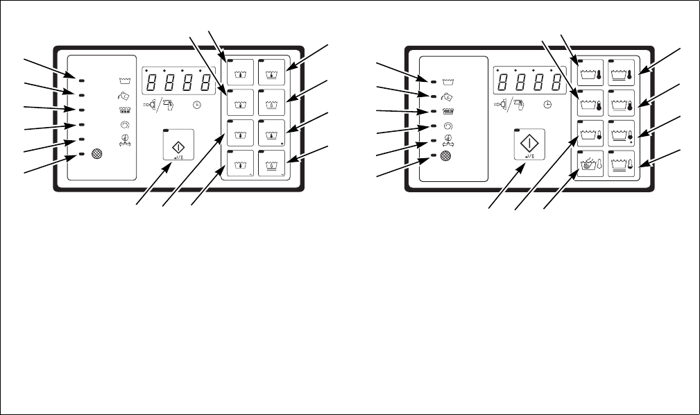
In RUN Mode the top left keypad selects Cycle 1, the
(∧) keypad directly below it selects Cycle 2, etc.
Figure 3 shows which keypad selects each cycle in
RUN Mode.
1. After entering PROGRAM Mode, display will
show “0000” or temperature (if machine is
configured for heat) or “tSFL”.
2. Press the (∧) keypad to enter Cycle
Programming Mode.
3. The display will reference cycles by number.
Cycle 1 will show first.
4. Use the (∧) or (∨) keypad to select cycle to be
edited.
5. Press START (Enter) keypad to move into the
menu of options.
© Copyright, Alliance Laundry Systems LLC – DO NOT COPY or TRANSMIT
Programming
15
F232157
Programming Vend Price
(For Earlier Models)
Setup Mode
NOTE: In SETUP Mode, certain machine
functions can be configured. The settings in this
mode are related to how the machine is equipped
from the factory. Usually, these would not be
changed in the field.
NOTE: Enter SETUP Mode through the
PROGRAM Mode. Refer to Entering Program
Mode.
1. Press (*) keypad. Display shows machine model
size (capacity). Displayed capacity must match
machine size.
2. Press (∧) keypad to change the capacity. (This
should already be set correctly from the factory,
and normally should never need to be changed).
3. Press START (Enter) keypad.
4. Display shows “FAr” or “CEL”.
NOTE: This option selects whether temperatures
display in degrees Fahrenheit (F) or Celsius (C), if
control is equipped with a temperature sensor.
Press the (∧) or (∨) keypad to change degrees
“FAr” or “CEL”.
5. Press START (Enter) keypad.
6. If model displays “HEAt” or “noHt”, change the
selection by pressing the (∧) or (∨) keypad.
7. If model displays “CArd” or “COIn”, skip to
step #10.
8. Press START (Enter) keypad to continue to the
next step.
9. “EFIL” or “nEFL” will display in certain models.
“EFIL” means the capability to control an extra
fill valve with programmable water level (same
as regular fills) is enabled. Machine MUST be
equipped with the extra valve for this to work
properly. “nEFL” means the extra fill valve
option is disabled or not installed on machine.
NOTE: If neither message displays, the extra fill
capability is not present. If either message displays,
changing the selection is an option by pressing the
(∧) or (∨) keypad. Press START (Enter) keypad
to continue to the next option.
10. If model displays the message “CArd” or
“COIn”, change the selection by pressing the (∧)
or (∨) keypad.
11. When correct, press START (Enter) keypad to
continue to the next selection.
NOTE: Select “COIn” for regular coin drop meter
or if coin inputs are used by accessory pay system.
Contact the manufacturer of the accessory pay
system if not working properly.
12. “bEEP” or “nobP” will display in certain models.
If “bEEP” is set, control will beep during Add
Bleach (Supply 2) and at end of cycle after
several seconds while displaying “dOnE”. If
“nobP” displays, control will NOT beep during
Add Bleach (Supply 2) or at end of cycle. This
does not affect the short beep when a keypad is
pressed or a coin is inserted and it does not affect
the beep during an alarm.
13. Press the (∧) or (∨) keypad to change “bEEP”/
“nobP” selection.
14. Press START (Enter) keypad to continue to next
step.
© Copyright, Alliance Laundry Systems LLC – DO NOT COPY or TRANSMIT
Programming
F232157
16
NOTE: If machine is equipped with a card reader,
or interfaces with a control/remote pay system,
setting “con1”/ “dEno” and “con2”/ “dEno” equal
to the vend start amount (“Strt”/ “Ant”) will allow
starting with one pulse and is recommended. The
card or central remote pay vend amount should
match the “Strt”/ “Ant” setting.
15. Display shows “con1”, “dEno” next, then a
number such as 25. This means that the coin 1
denomination is 25 cents for single coin meters.
For example, a U.S. quarter coin meter would be
set for 25 cents or this would be the amount for
one of the two denominations for a dual coin
meter, such as a U.S. quarter for a dollar/quarter
dual coin meter. The vend price programmed
above will count down by this amount each time
a coin is added.
16. Press the (∧) or (∨) keypad to decrease or
increase this amount.
17. When correct, press START (Enter) keypad.
18. Display shows “con2”, “dEno” next, then a
number such as 100. This means that the coin 2
denomination is 100 cents. This is the coin
denomination for coin meters that can process
two types of coins – such as a U.S. quarter/dollar
coin meter. The second coin input would be one
dollar. For single coin meters, press START
(Enter) keypad to continue. The vend price
programmed above will count down by this
amount each time this second coin type is added.
19. Press the (∧) or (∨) keypad to decrease or
increase this amount.
20. When correct, press START (Enter) keypad.
21. Display shows “Strt”, “Ant” next, then a number
such as 150. This means that the start amount is
150 cents. This is the vend price required to
operate a wash cycle.
22. Press the (∨) or (∧) keypad to decrease or
increase this amount.
23. When correct, press START (Enter) keypad.
24. Display shows “0000” when complete. Return
the Program/Run switch to the right and close the
lid. The display will show new vend price.
Cycle and Error Count
The control logs cycle count (total of all cycles
completed).
1. To read, enter PROGRAM Mode. Refer to
Entering Program Mode.
2. Press START (Enter) keypad. Display will show
the cycle count.
3. Press START (Enter) keypad. Display will show
certain error conditions that may have been
recorded by the control.
4. Read the information when consulting technical
assistance as needed.
5. Step through the error log by pressing START
(Enter) keypad repeatedly until display reverts to
normal PROGRAM Mode (“0000” or
temperature).
Programming Cycle Segments
The machine is preprogrammed with eight wash cycle
formulas that can be edited.
To edit any of these cycles, enter PROGRAM Mode.
Refer to Entering Program Mode. In PROGRAM
Mode, cycles are selected by number (1 through 8) as
opposed to the RUN Mode, where cycles are selected
by pressing one of the eight corresponding keypads.
The keypads must serve different functions in each
mode because there are more functions than keypads
in PROGRAM Mode.
In RUN Mode the top left keypad selects Cycle 1, the
(∧) keypad directly below it selects Cycle 2, etc.
Figure 3 shows which keypad selects each cycle in
RUN Mode.
1. After entering PROGRAM Mode, display will
show “0000” or temperature (if machine is
configured for heat).
2. Press the (∧) keypad to enter Cycle Programming
Mode. The display will reference cycles by
number. Cycle 1 will show first.
3. Use the (∧) or (∨) keypad to select cycle to be
edited.
4. Press START (Enter) keypad to move into the
menu of options.
© Copyright, Alliance Laundry Systems LLC – DO NOT COPY or TRANSMIT
Programming
17
F232157
Figure 3
NOTE: If the version of control in machine is
capable of reading temperature, pressing the
START (Enter) keypad while a wash is running
will cause the display to show temperature.
Depending on version of control, this will either
revert to minutes remaining after several seconds,
or START (Enter) keypad must be pressed a
second time to revert to minutes remaining.
CHM482R CHM488R
1Cycle 1 9START (Enter) Keypad
2Cycle 2 10 “Clean Filter” Indicator LED (Active only for
3Cycle 3 C60FX, C80 and C125 Models)
4Cycle 4/ “∧” Edit 11 Door Open LED
5Cycle 5 12 Spin Cycle LED
6Cycle 6 13 Rinse Cycle LED
7Cycle 7 14 Add Bleach LED
8Cycle 8/ “∨” Edit
60C 60C
40C 40C
95C 95C
<
<
30C
CHM488R
CHM482R
WASH
ADD
BLEACH
RINSE
SPIN
DOOR
NORMAL
NORMAL
QUICK AS QUICK WASH
HEAVY SOIL
DELICATE
RM RESS
PERM PRESS
HOT
WARM
HOT
HOT
WARM
COLD
WARM
COLD
START
PE P
WH
DOMESTIC MODELS INTERNATIONAL MODELS
1
5
6
7
8
4
10
2
39
11
12
13
14
15
1
5
6
7
8
4
10
2
39
11
12
13
14
15

© Copyright, Alliance Laundry Systems LLC – DO NOT COPY or TRANSMIT
Programming
F232157
18
Options for Each Segment
Cycle Steps Available
(NOTE: WASH, ADD BLEACH, RINSE
and SPIN LEDs light ONLY when a
cycle formula is in operation.)
Display Setting Options for Cycle Steps
Wash 1 (displayed as “USH1”)
Time for Agitation (excludes fill, drain,
spin and heat)
GEnt 0 or 2-30 minutes in agitation step (increases/decreases in
one-minute increments). Refer to Table 3 for operation of
each agitation segment
norn
Fill valves (temperature) CFIL Cold, Hot or Both (warm) water fills or Extra fill (must be
configured for “EFIL” in SETUP Mode)
HFIL
bFIL
EFIL
Fill water level control LO Low, Medium or High water level
nEd
HI
Supply SUP0 SUP0 for No Supply or Supply 1-3,6 (Refer to Table 2 for
operation of each supply selection)
SUP1
SUP2
SUP3
SUP6
Heat (Models with heat or heat capability) HEAt 00F (no heat for segment) or 80°F to 205°F
00C (no heat for segment) or 27°C to 95°C
noHt
Drain (Final segment drains in stop
routine if No Drain is programmed)
drAI Drain or No Drain (if No Drain programmed, will skip spin
segment associated with Drain segment)
nodr
Spin time SPIn 00 for No Spin or 30-240 seconds (increases/decreases in
one-second increments)
tInE
Wash 2 (displayed as “USH2”)
Time for Agitation (excludes fill, drain,
spin and heat)
GEnt 0 or 2-20 minutes in agitation step (increases/decreases in
one-minute increments). Refer to Table 3 for operation of
each agitation segment
norn
Fill valves (temperature) CFIL Cold, Hot or Both (warm) water fills or Extra fill (must be
configured for “EFIL” in SETUP Mode)
HFIL
bFIL
EFIL
Fill water level control LO Low, Medium or High water level
nEd
HI
Supply SUP0 SUP0 for No Supply or Supply 1-3,6 (Refer to Table 2 for
operation of each supply selection)
SUP1
SUP2
SUP3
SUP6
Table 1 (continued)

© Copyright, Alliance Laundry Systems LLC – DO NOT COPY or TRANSMIT
Programming
19
F232157
Table 1 (continued)
Cycle Steps Available
(NOTE: WASH, ADD BLEACH, RINSE
and SPIN LEDs light ONLY when a
cycle formula is in operation.)
Display Setting Options for Cycle Steps
Heat (Models with heat or heat capability) HEAt 00F (no heat for segment) or 80°F to 205°F
00C (no heat for segment) or 27°C to 95°C
noHt
Drain (Final segment drains in stop
routine if No Drain is programmed)
drAI Drain or No Drain (if No Drain programmed, will skip spin
segment associated with Drain segment)
nodr
Spin time SPIn 00 for No Spin or 30-240 seconds (increases/decreases in
one-second increments)
Wash 3 (displayed as “USH3”)
Time for Agitation (excludes fill, drain,
spin and heat)
GEnt 0 or 2-15 minutes in agitation step (increases/decreases in
one-minute increments). Refer to Table 3 for operation of
each agitation segment
norn
Fill valves (temperature) CFIL Cold, Hot or Both (warm) water fills or Extra fill (must be
configured for “EFIL” in SETUP Mode)
HFIL
bFIL
EFIL
Fill water level control LO Low, Medium or High water level
nEd
HI
Supply SUP0 SUP0 for No Supply or Supply 1-3,6 (Refer to Table 2 for
operation of each supply selection)
SUP1
SUP2
SUP3
SUP6
Heat (Models with heat or heat capability) HEAt 00F (no heat for segment) or 80°F to 205°F
00C (no heat for segment) or 27°C to 95°C
noHt
Drain (Final segment drains in stop
routine if No Drain is programmed)
drAI Drain or No Drain (if No Drain programmed, will skip spin
segment associated with Drain Segment)
nodr
Spin time SPIn 00 or 30-240 seconds (increases/decreases in one-second
increments)
Wash 4 (displayed as “USH4”)
Time for Agitation (excludes fill, drain,
spin and heat)
GEnt 0 or 2-15 minutes in agitation step (increases/decreases in
one-minute increments). Refer to Table 3 for operation of
each agitation segment
norn
Fill valves (temperature) CFIL Cold, Hot or Both (warm) water fills or Extra fill (must be
configured for “EFIL” in SETUP Mode)
HFIL
bFIL
EFIL
Fill water level control LO Low, Medium or High water level
nEd
HI
Table 1 (continued)

© Copyright, Alliance Laundry Systems LLC – DO NOT COPY or TRANSMIT
Programming
F232157
20
Table 1 (continued)
Cycle Steps Available
(NOTE: WASH, ADD BLEACH, RINSE
and SPIN LEDs light ONLY when a
cycle formula is in operation.)
Display Setting Options for Cycle Steps
Supply SUP0 SUP0 for No Supply or Supply 1-3,6 (Refer to Table 2 for
operation of each supply selection)
SUP1
SUP2
SUP3
SUP6
Heat (Models with heat or heat capability) HEAt 00F (no heat for segment) or 80°F to 205°F
00C (no heat for segment) or 27°C to 95°C
noHt
Drain (Final segment drains in stop
routine if No Drain is programmed)
drAI Drain or No Drain (if No Drain programmed, will skip spin
segment associated with Drain segment)
nodr
Spin time SPIn 00 for No Spin or 30-240 seconds (increases/decreases in
one-second increments)
tInE
Rinse 1 (displayed as “rIn1”)
Time for Agitation (excludes fill, drain,
spin and heat)
GEnt 0 or 2-15 minutes in agitation step (increases/decreases in
one-minute increments). Refer to Table 3 for operation of
each agitation segment
norn
Fill valves (temperature) CFIL Cold, Hot or Both (warm) water fills or Extra fill (must be
configured for “EFIL” in SETUP Mode)
HFIL
bFIL
EFIL
Fill water level control LO Low, Medium or High water level
nEd
HI
Supply SUP0 SUP0 for No Supply or Supply 1-3,6 (Refer to Table 2 for
operation of each supply selection)
SUP1
SUP2
SUP3
SUP6
Heat (Models with heat or heat capability) HEAt 00F (no heat for segment) or 80°F to 205°F
00C (no heat for segment) or 27°C to 95°C
noHt
Drain (Final segment drains in stop
routine if No Drain is programmed)
drAI Drain or No Drain (if No Drain programmed, will skip spin
segment associated with Drain segment)
nodr
Spin time SPIn 00 for No Spin or 30-240 seconds (increases/decreases in
one-second increments)
Table 1 (continued)

© Copyright, Alliance Laundry Systems LLC – DO NOT COPY or TRANSMIT
Programming
21
F232157
Table 1 (continued)
Cycle Steps Available
(NOTE: WASH, ADD BLEACH, RINSE
and SPIN LEDs light ONLY when a
cycle formula is in operation.)
Display Setting Options for Cycle Steps
Rinse 2 (displayed as “rIn2”)
Time for Agitation (excludes fill, drain,
spin and heat)
GEnt 0 or 2-15 minutes in agitation step (increases/decreases in
one-minute increments). Refer to Table 3 for operation of
each agitation segment
norn
Fill valves (temperature) CFIL Cold, Hot or Both (warm) water fills or Extra fill (must be
configured for “EFIL” in SETUP Mode)
HFIL
bFIL
EFIL
Fill water level control LO Low, Medium or High water level
nEd
HI
Supply SUP0 SUP0 for No Supply or Supply 1-3,6 (Refer to Table 2 for
operation of each supply selection)
SUP1
SUP2
SUP3
SUP6
Heat (Models with heat or heat capability) HEAt 00F (no heat for segment) or 80°F to 205°F
00C (no heat for segment) or 27°C to 95°C
noHt
Drain (Final segment drains in stop
routine if No Drain is programmed)
drAI Drain or No Drain (if No Drain programmed, will skip spin
segment associated with Drain segment)
nodr
Spin time SPIn 00 or 30-240 seconds (increases/decreases in one-second
increments)
Rinse 3 (displayed as “rIn3”)
Time for Agitation (excludes fill, drain,
spin and heat)
GEnt 0 or 2-15 minutes in agitation step (increases/decreases in
one-minute increments). Refer to Table 3 for operation of
each agitation segment
norn
Fill valves (temperature) CFIL Cold, Hot or Both (warm) water fills or Extra fill (must be
configured for “EFIL” in SETUP Mode)
HFIL
bFIL
EFIL
Fill water level control LO Low, Medium or High water level
nEd
HI
Supply SUP0 SUP0 for No Supply or Supply 1-3,6 (Refer to Table 2 for
operation of each supply selection)
SUP1
SUP2
SUP3
SUP6
Table 1 (continued)

© Copyright, Alliance Laundry Systems LLC – DO NOT COPY or TRANSMIT
Programming
F232157
22
Table 1 (continued)
Cycle Steps Available
(NOTE: WASH, ADD BLEACH, RINSE
and SPIN LEDs light ONLY when a
cycle formula is in operation.)
Display Setting Options for Cycle Steps
Heat (Models with heat or heat capability) HEAt 00F (no heat for segment) or 80°F to 205°F
00C (no heat for segment) or 27°C to 95°C
noHt
Drain (Final segment drains in stop
routine if No Drain is programmed)
drAI Drain or No Drain (if No Drain programmed, will skip spin
segment associated with Drain segment)
nodr
Spin time SPIn 00 for No Spin or 30-240 seconds (increases/decreases in
one-second increments)
tInE
Rinse 4 (displayed as “rIn4”)
Time for Agitation (excludes fill, drain,
spin and heat)
GEnt 0 or 2-15 minutes in agitation step (increases/decreases in
one-minute increments). Refer to Table 3 for operation of
each agitation segment
norn
Fill valves (temperature) CFIL Cold, Hot or Both (warm) water fills or Extra fill (must be
configured for “EFIL” in SETUP Mode)
HFIL
bFIL
EFIL
Fill water level control LO Low, Medium or High water level
nEd
HI
Supply SUP0 SUP0 for No Supply or Supply 1-3,6 (Refer to Table 2 for
operation of each supply selection)
SUP1
SUP2
SUP3
SUP6
Heat (Models with heat or heat capability) HEAt 00F (no heat for segment) or 80°F to 205°F
00C (no heat for segment) or 27°C to 95°C
noHt
Drain (Final segment drains in stop
routine if No Drain is programmed)
drAI Drain or No Drain (if No Drain programmed, will skip spin
segment associated with Drain segment)
nodr
Spin time SPIn 00 for No Spin or 1-10 minutes (increases/decreases in one-
minute increments)
Table 1
© Copyright, Alliance Laundry Systems LLC – DO NOT COPY or TRANSMIT
Programming
23
F232157
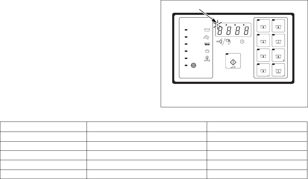
NOTE: If the wash load becomes out of balance,
the machine will attempt to balance the load. After
three failed attempts the display will light the
leftmost digit and a lower spin will be used to
complete the cycle. Refer to Figure 4.
Figure 4
*NOTE: ADD BLEACH LED lights if Supply 2 is
the only supply programmed. If set up for
"bEEP"(refer to SETUP Mode section), buzzer will
sound on and off for the first eight seconds. The
Supply 2 and ADD BLEACH LED remain on for
45 seconds or until the fill is complete, whichever
comes first.
**NOTE: Selecting "EFIL" (Extra fill) in SETUP
Mode will remove supply 6 as optional supply
signals.
CHM524R
1Out-of-Balance LED
WASH
ADD
BLEACH
RINSE
SPIN
DOOR
NORMAL
NORMAL
QUICK ASQUICK WASH
HEAVY SOI L
DELICATE
RM RESS
PERM PRESS
HOT
WAR M
HOT
HOT
WAR M
COLD
WAR M
COLD
STA R T
PE P
WH
1
Supply Programmed External Chemical Supply Signal Compartment Flushed
SUP0 None None
SUP1 Supply 1 Compartment 1
SUP2 Supply 2* Compartment 2
SUP3 Supply 3 Compartment 3
SUP6 Supply 6** Compartment 1 and 2
Table 2
© Copyright, Alliance Laundry Systems LLC – DO NOT COPY or TRANSMIT
Programming
F232157
24
To Edit an Entire Wash Cycle
Formula
1. Enter PROGRAM Mode. Refer to Entering
Program Mode.
2. Press the (∧) keypad until display shows
“CY01”.
3. Press the (∧) or (∨) keypad until cycle to be
edited is displayed.
4. Press START (Enter) keypad to select the cycle
desired. Refer to Figure 3, showing which cycle
number corresponds to each keypad when in
RUN Mode.
Agitation for the cycle
5. With display showing “CY_x” (x = cycle
number), press the START (Enter) keypad.
6. Display shows either “norn” (for normal
agitation), or “GEnt” (for gentle agitation). Refer
to Table 3.
7. Press the (∧) or (∨) keypad to alter the selection,
or the START (Enter) keypad to continue.
Wash 1 – Wash 4
NOTE: Programming a time other than “00” for
Wash 1 will make the WASH indicator LED light
while this step is running, but NOT in PROGRAM
Mode.
8. The main display shows “USH1” indicating you
are in the Wash segment (number will reflect
selected Wash cycle 1-4).
9. Press START (Enter) keypad. Display shows
agitation time during the step: “00” (skips
segment) or 2-30 minutes. Wash 2 agitation’s
time can be 2-20 minutes, 2-15 minutes for Wash
3 and Wash 4 or “00” to skip Wash 2, Wash 3 or
Wash 4. This is the time after the fill and before
the drain and does not include spin time or time
to first reach a programmed temperature (if
machine is configured for heat).
10. Press the (∧) or (∨) keypad to alter the selection,
or the START (Enter) keypad to continue.
11. Display shows “CFIL”, “HFIL”, “bFIL” or
“EFIL” for Cold, Hot, Both (warm) or Extra fill,
respectively.
12. Press the (∧) or (∨) keypad to alter the selection,
or the START (Enter) keypad to continue.
NOTE: Extra fill (“EFIL”) is possible only if
configured for “EFIL” in SETUP Mode. If model is
not configured for the extra fill valve, “nEFL” will
display. If configured, a third valve can be
controlled.
13. Display shows “LO”, “nEd”, or “HI” for Low,
Medium, or High water level, respectively.
14. Press the (∧) or (∨) keypad to alter the
selection, or the START (Enter) keypad to
continue.
15. Display shows “SUP0”, “SUP1”, “SUP2”,
“SUP3”, or “SUP6” (or “S 12” depending on
version of control). Refer to Table 2 for operation
of each supply selection.
16. Press the (∧) or (∨) keypad to alter the selection,
or the START (Enter) keypad to continue.
NOTE: If programmed for “SUP2”, the ADD
BLEACH indicator LED light turns on and is set
up for “bEEP” the buzzer sounds for the first eight
seconds Supply 2 is on.
Heated Models Only
17. Display shows temperature in degrees F or C.
Display will show degrees F if configured for
“FAr” in SETUP Mode, or degrees C if
configured for “CEL” in SETUP Mode. Range is
80°F to 205°F, or 00F (no heat for segment), or
27°C to 95°C, or 00C (no heat for segment).
18. Press the (∧) keypad to increase, or (∨) keypad
to decrease temperature in one-degree
increments.
The control will energize heat and pause cycle timing
for up to 40 minutes until the programmed
temperature is first reached.
Display Meaning
norn12 seconds forward, 3 seconds pause,
12 seconds reverse, 3 seconds pause, and
repeat for programmed time.
GEnt 3 seconds forward, 12 seconds pause,
3 seconds reverse, 12 seconds pause and
repeat for programmed time
Table 3
To prevent personal injury, avoid contact
with inlet water temperatures higher than
125° Fahrenheit (51° Celsius) and hot
surfaces.
W748
WARNING

© Copyright, Alliance Laundry Systems LLC – DO NOT COPY or TRANSMIT
Programming
25
F232157
NOTE: If temperature is not reached after
40 minutes, control resumes cycle.
After cycle resumes, control will attempt to maintain
programmed temperature if it senses water in the
machine.
NOTE: Temperature display applies ONLY if
machine is configured for “HEAt” in SETUP
Mode. Machine must be equipped with electric or
steam heat and a temperature sensor. If configured
for “noHt” (no heat capability) in SETUP Mode,
temperature display does not appear in the
segment. After temperature setting, control will
skip to “drAI”/“nodr” or Spin Time, depending on
version.
19. If display shows “drAI”/“nodr” during segment
programming, a drain step option will appear at
the end of the segment.
20. Select “drAI” for a drain step followed by an
optional spin. Select “nodr” for no drain step.
NOTE: The machine will proceed directly to the
next segment if “nodr”.
21. Change the selection by pressing the (∧) or (∨)
keypad, or the START (Enter) keypad to
continue.
22. If “drAI” is selected (or if your model does not
provide the option of selecting “drAI”/“nodr”),
the display will show “SPIn” one second, “tInE”
one second, and then the time for spin: “00” (no
spin) or 30-240 seconds.
23. Change the selection by pressing the (∧) or (∨)
keypad or the START (Enter) keypad to continue.
Rinse 1 – Rinse 4
NOTE: Programming a time other than “00” for
this step will make the RINSE indicator LED light
while this step is running, but not in PROGRAM
Mode.
24. The main display shows “rIN1” indicating you
are in the Rinse segment (number will represent
Rinse cycle selected 1-4).
25. Press START (Enter) keypad. Display shows the
time for agitation during the step: “00” (skips
segment) or 2-15 minutes. This is the time after
the fill and before the drain and does not include
spin time.
26. Press the (∧) or (∨) keypad to alter the selection,
or the START (Enter) keypad to continue.
27. Display shows “CFIL”, “HFIL”, “bFIL” or
“EFIL” for Cold, Hot, Both (warm) or Extra fill.
28. Press the (∧) or (∨) keypad to alter the selection,
or the START (Enter) keypad to continue.
NOTE: Extra fill (“EFIL”) is possible only if
configured for “EFIL” in SETUP Mode. If
configured, a third valve can be controlled.
29. Display shows “LO”, “nEd”, or “HI” for Low,
Medium, or High water level, respectively.
30. Press the (∧) or (∨) keypad to alter the selection,
or the START (enter) keypad to continue.
31. Display shows “SUP0”, “SUP1”, “SUP2”,
“SUP3”, or “SUP6” (or “S 12” depending on
version of control). Refer to Table 2 for operation
of each supply selection.
32. Press the (∧) or (∨) keypad to alter the selection,
or the START (Enter) keypad to continue.
NOTE: If programmed for “SUP2”, the ADD
BLEACH indicator LED light turns on and is set
up for “bEEP” the buzzer sounds for the first eight
seconds Supply 2 is on.
Heated Models Only
33. Display shows temperature in degrees F or C.
Display will show degrees F if configured for
“FAr” in SETUP Mode, or degrees C if
configured for “CEL” in SETUP Mode. Range is
80°F to 205°F, or 00F (no heat for segment), or
27°C to 95°C, or 00C (no heat for segment).
34. Press the (∧) keypad to increase, or (∨) keypad
to decrease temperature. Temperature changes in
one-degree increments.
The control will energize heat and pause cycle timing
for up to 40 minutes until the programmed temperature
is first reached.
NOTE: If temperature not reached after
40 minutes, control resumes cycle.
After cycle resumes, control will attempt to maintain
programmed temperature if it senses water in the
machine.
To prevent personal injury, avoid contact
with inlet water temperatures higher than
125° Fahrenheit (51° Celsius) and hot
surfaces.
W748
WARNING

© Copyright, Alliance Laundry Systems LLC – DO NOT COPY or TRANSMIT
Programming
F232157
26
NOTE: Temperature display applies ONLY if
machine is configured for “HEAt” in SETUP
Mode. Machine must be equipped with electric or
steam heat and a temperature sensor. If configured
for “noHt” (no heat capability) in SETUP Mode,
temperature display does not appear in the
segment. After temperature setting, control will
skip to “drAI”/“nodr” or Spin Time, depending on
version. If “HEAt”/ “noHt” does not appear in
SETUP Mode, no heating is possible.
35. If display shows “drAI”/“nodr” during segment
programming, a drain step option will appear at
the end of the segment.
36. Select “drAI” for a drain step followed by an
optional spin. Select “nodr” for no drain step.
NOTE: The machine will proceed directly to the
next segment if “nodr”.
37. Change the selection by pressing the (∧) or (∨)
keypad or the START (Enter) keypad to continue.
38. If “drAI” is selected (or if your model does not
provide the option of selecting “drAI”/“nodr”),
the display will show “SPIn” one second, “tInE”
one second, and then the time for spin: “00” (no
spin) for 30-240 seconds IF you are in Rinse 1, 2,
or 3. If you are in Rinse 4, the time for spin will
show 0 or 1-10 minutes.
39. Change the selection by pressing the (∧) or (∨)
keypad, or the START (Enter) keypad to
continue.
IMPORTANT: The spin time in Rinse 4 is
programmed in minutes (0-10 minutes, in
one-minute increments), while other spins are in
seconds to allow for shorter times (such as
45 seconds). (Rinse 4 segment should usually be
used as the final rinse, even where there may be
fewer than four rinses. Program zero time for
preceding rinses you wish to exclude.)
40. Display shows “0000” if control cannot read
temperature or a temperature if control is capable
of a temperature reading.
41. Exit PROGRAM Mode by moving the Program/
Run switch back to the right as seen from the
front of the machine.
NOTE: The SPIN indicator LED will automatically
light during the wash cycle when the last spin
programmed in a cycle is operating (regardless of
which segment).
Abnormal Conditions
Door Will Not Lock
If the door handle has not been properly positioned to
allow locking the door, the control will sense this and
retract the door lock solenoid. The display will show
“----” for about 5 seconds, then will flash “SHUt”/
“dOOr” for about 5 seconds while sounding the
buzzer, prompting the user to close the door properly.
The DOOR indicator LED then lights. The machine
user should properly shut the door, then press START
(Enter) again. If the door is still not locking correctly,
the process above will repeat up to five times. After
this, the display flashes “CAnt”/“LOC” (cannot lock
door). The user can cause this to start over (five more
attempts) by pressing START (Enter) keypad twice. If
this continues, it indicates a problem, and a qualified
service technician should be consulted.
Door Open During Operation
If the control senses either a momentary or sustained
open door while the machine is operating in a wash
cycle, the control immediately attempts to halt rotation
of the cylinder. All outputs not required to effect rapid
halting of the cylinder rotation de-energize
immediately. The message “dOOr” then displays as
long as the condition persists. Regardless of the
duration of the open door condition, once it is
recognized by the control, the control aborts the cycle
and goes to the stop routine even if the door is closed.
Excessive Fill Time
Fill times exceeding 10 minutes cause the cycle to
abort. Display flashes “StOP”/“FILL” and sounds the
buzzer for 10 seconds prior to entering the stop routine
(display shows “01” minutes remaining while in the
stop routine). The Fill Error Count will increase by
one. Refer to Cycle and Error Count section.
Out-of-Balance
If the machine goes out of balance, the machine will
attempt to balance the load. After three attempts, the
display will light the leftmost digit and a lower spin
will be used.
Operating the machine with severe out-of-
balance loads could result in personal
injury and serious equipment damage.
W728
WARNING
© Copyright, Alliance Laundry Systems LLC – DO NOT COPY or TRANSMIT
Programming
27
F232157
Drain Error (For Models With Firmware ID
Code “C2dS” and “CvdS”)
If machine has not drained within 4 minutes 15
seconds, display flashes “Erdn”, time remaining, and
buzzer beeps. The buzzer stops beeping after 30
seconds while display flashes “Erdn” until machine
empties. If machine empties, ending Drain Error
condition, display stops flashing, buzzer turns off, and
remaining cycle time displays as the cycle resumes.
If machine does not empty, display continues flashing
“Erdn”. The drain error counter increases by one.
Refer to Cycle and Error Count section.
Clogged Filter (All C80 and C60 X Voltage
ONLY Models)
A clogged filter can cause the inverter drive to run at
an elevated temperature. If the control senses an
elevated inverter drive temperature, the bottom
indicator LED on front panel decal lights. Check and
clean the drive compartment filter if necessary. The
light turns off AFTER one cycle runs at normal
temperature.
Door Will Not Unlock
If the door solenoid cannot retract (unlocking the door)
at the end of the stop routine, the display will show
“----” for ten seconds. In all models except an early
version of the 125, control attempts to unlock the door
again by pulsing the door solenoid every ten seconds
for a total of five times. An early version of the 125
model has a door unlock button.
The display then flashes “CAnt”/“OPEn”, indicating it
cannot unlock the door. This indicates a problem, and
a qualified service technician should be consulted.
At the end of a cycle or at power up, before the control
will allow the door to unlock, control checks for low,
medium or high water level. Control allows the door to
unlock only when machine is empty. If any water level
is indicated, display shows “FULL” while keeping all
outputs off. This condition could indicate a slow drain
system or a mechanical blockage of the drain. Contact
an authorized service person, mentioning display on
control.
On Board Battery Problem
If certain functions require the on board battery
(dependent on specific machines) and if battery charge
is low, or battery is removed, the control will display
“bAtt”. This is displayed several seconds after power
is applied to the control. Contact an authorized service
person if condition continues.
Temperature Probe Malfunction
If display shows “+SFL”, “-19C”, or “00F”, the
temperature probe may need to be replaced. If problem
persists after changing probe, contact an authorized
service person.
Rapid Advance (For Models With
Firmware ID Code “C2dS” and
“CvdS”)
Enabling Rapid Advance
NOTE: Rapid Advance can only be used during a
cycle operation.
To enable Rapid Advance while a cycle is in progress,
machine must be in PROGRAM Mode. Refer to
Entering Program Mode.
How to Rapid Advance During All Steps
(Except First Fill Step)
1. Make sure Rapid Advance is enabled.
2. Enter PROGRAM Mode. Refer to Entering
Program Mode.
3. Press the Advance (∧) keypad to advance to
desired step.
4. Display will show recalculated time remaining.
How to Rapid Advance (During First Fill
Step)
1. Make sure Rapid Advance is enabled.
2. While machine is filling with water, enter
PROGRAM Mode. Refer to Entering Program
Mode.
3. To advance to the next step, press START
(Enter) keypad to turn off the ability to change
cycles.
4. Press the Advance (∧) keypad to advance to
desired step.
5. Display will show recalculated time remaining.
NOTE: If control is set up for ‘Etin’, the remaining
cycle time after using Rapid Advance step is
calculated as if control was configured for ‘Ptin’.
This is because any time estimations following
advance would be inaccurate. After the cycle ends,
and the ADVANCE Mode is disabled, the next cycle
display remaining cycle time based on the ‘Etin’
configuration.
© Copyright, Alliance Laundry Systems LLC – DO NOT COPY or TRANSMIT
Programming
F232157
28
Agitation Step
Advance the cycle by pressing “∧” keypad to skip to
the drain step. Filling, supply flushing and other
signals turn off. Cycle remaining time is recalculated
as the total remaining time after the agitation.
Drain Step
Advance the cycle by pressing “∧” keypad to skip the
drain step and the following spin step. The spin step is
skipped because the drain step needs to be completed
to balance the load. The next programmed step after
the spin begins. Cycle remaining is recalculated as the
total remaining time after the drain and spin steps.
Spin Step
Advance the cycle by pressing “∧” keypad to skip the
spin step. The next step after the spin begins. Cycle
remaining is recalculated as the total remaining time
after the spin step.
Temporary Free Mode
An authorized operator can enable a Free Cycle
operation that overrides the programmed vend start
amount. After running the Free Cycle, which can be
any of the eight cycles, the control reverts to the usual
programmed vend.
NOTE: The cycle counter DOES count the free
cycle.
•To run a temporary Free Cycle, follow the steps
below. Enter PROGRAM Mode. Display shows
“0000” or temperature or “tSFL” (depending on
version of control).
•Press the (∨) keypad. Display shows “FrEE”.
•While display shows “FrEE”, return the
Program/Run switch to the RUN position. Then
press a cycle keypad to select one of the eight
cycles. Press START (Enter) to begin the cycle.
When the cycle concludes, vend reverts to the
programmed amount.
Test Cycle
The test cycle provides a convenient means of
troubleshooting and testing all machine functions
quickly.
1. Enter PROGRAM Mode. Display shows “0000”
or temperature or “tSFL” (depending on version
of control).
2. Press the (∨) keypad. Display shows “FrEE”.
3. Press the START (Enter) keypad. Display shows
“tESt”.
4. Return the Program/Run switch to the right.
Display will show the vend price.
5. Enter coins or make payment so that the vend
amount counts down. When vend is satisfied, the
display will show “tESt” and the START (Enter)
keypad LED will flash on and off. Press the
START (Enter) keypad to begin the test cycle.
6. Press START (Enter) keypad. The door locks and
the TEST Mode starts.
7. Display shows “SPC?”. This is a special factory
test procedure. Simply ignore it and the machine
will advance into the test cycle after about
five seconds or go to “bAL?” if variable-speed.
NOTE: For variable-speed models ONLY, display
shows “bAL?”. This is a factory test. Disregard the
display. Machine will begin the test cycle after a
few seconds.

© Copyright, Alliance Laundry Systems LLC – DO NOT COPY or TRANSMIT
Programming
29
F232157
Permanent Factory Diagnostic Test
Cycle
Warm fill to low water level Display flashes “bFIL”/ “LO” (keypad WASH LED on), no agitation
Outputs: Motor OFF, Drain closed, hot fill on, cold fill on
Pause after reaching low
water level
Display shows “LO” (no flashing), LOW water level dot ON, no agitation (keypad WASH
LED on); pauses until operator presses (∧) keypad
Outputs: Motor OFF, Drain closed
Drain (can advance to next
step by pressing (∧) keypad
here)
Display shows “drAI”, no agitation (keypad WASH LED on)
Outputs: Motor OFF, Drain open
Cold fill to medium level Display flashes “CFIL”/ “nEd” (keypad WASH LED on), no agitation.
Outputs: Motor OFF, Drain closed, cold fill on
Pause after reaching
medium water level
Display shows “nEd” (no flashing), LOW and MEDIUM water level dots ON no agitation
(keypad WASH LED on); pauses until operator presses ^ keypad
Outputs: Motor OFF, Drain closed
Hot fill to high level Display flashes “HFIL”/ “HI” (keypad WASH LED on), no agitation.
Outputs: Motor OFF, Drain closed, hot fill on
Pause after reaching high
water level
Display shows “HI” (no flashing), LOW, MEDIUM, & HIGH water level dots ON, no
agitation (keypad WASH LED on); pauses until operator presses ^ keypad
Outputs: Motor OFF, Drain closed
Heat to 45°C (110°F)
SKIPS THIS STEP if
machine does not have heat
capability (“noHt” selected
in SETUP Mode)
Display flashes “HEAT” and the temperature inside the machine while agitating in forward
and reverse; continues until temperature reaches 45°C (110°F), then advances to next step.
(keypad WASH LED on)
Outputs: Motor alternates forward 12 seconds, off 3 seconds, reverse 12 seconds, off
3 seconds and repeats; Drain closed; Heat ON UNTIL 45°C (110°F) reached
Extra fill spare – 5 seconds
(skips this if not selected in
SETUP Mode)
Display flashes “EFIL” (keypad RINSE LED on)
Outputs: Motor alternates forward 12 seconds, off 3 seconds, reverse 12 seconds, off
3 seconds and repeats; Drain closed; “S4” output ON.
Supply 1: 5 seconds (Heat
signal also on (IF at least
low water level – verifies
output even if not heated
model)
Display shows “SUP1” (keypad WASH LED on)
Outputs: Motor alternates forward 12 seconds, off 3 seconds, reverse 12 seconds, off
3 seconds and repeats; Drain closed; Supply 1 ON, HT ON, cold fill ON
Supply 2: 5 seconds (Heat
on also)
Display shows “SUP2” (keypad ADD BLEACH LED on)
Outputs: Motor alternates forward 12 seconds, off 3 seconds, reverse 12 seconds, off
3 seconds and repeats; Drain closed; Supply 2 ON, HT ON, cold fill ON
Supply 3: 5 seconds (Heat
on also)
Display shows “SUP3” (keypad RINSE LED on)
Outputs: Motor alternates forward 12 seconds, off 3 seconds, reverse 12 seconds, off
3 seconds and repeats; Drain closed; Supply 3 ON, HT ON, cold fill ON
Pause 5 seconds, then
Forward wash speed –
2 minutes
Display shows “For”
Outputs: Motor operates wash speed forward; drain closed
Table 4 (Continued)
© Copyright, Alliance Laundry Systems LLC – DO NOT COPY or TRANSMIT
Programming
F232157
30
Table 4
(*) For certain 125 models, the RPM may display.
NOTE: ON appears ONLY where motor control
outputs are on (otherwise they are off). Outputs
referenced are on control unit fuse board. Outputs
are as labeled on the fuse board.
Table 5
NOTE: For variable-speed machines smaller than
C80, SPn1 and SPn2 are not the same speed.
Table 4 (Continued)
Pause 5 seconds, then
Reverse wash speed –
2 minutes, then pause
several seconds before
entering drain (next step)
Display shows “rEv”
Outputs: Motor operates wash speed reverse; drain closed
Drain (cannot advance to
spin here)
For 2 speed models: Display flashes “drAI”/ “For” (keypad RINSE LED on)
For variable-speed models: Display flashes “drAI”/ “For” while operating in low speed
forward; then flashes “drAI”/ “dISt” while operating at distribution speed.
If balance fails, repeats the “drAI”/ “For” then “drAI”/ “dISt” sequence above and balance
indicator is on during “drAI”/ “For” message (rebalance attempt). Tries up to 10 times in
TEST cycle then aborts test cycle.
Outputs: Drain closed for first part of step (less than 20 seconds), then drain off.
2 speed models: Wash speed forward
Variable-speed: Forward during “drAI”/ “For”; distribution during “drAI”/ “dISt”.
Spin – 3 minutes For 2 speed models: display shows “SPn” (keypad SPIN LED on)
For variable-speed models: display shows “SPn1” (keypad SPIN LED on)
Outputs: Spin (low spin for variable speed-see motor chart below)(*)
Highest Spin speed
(variable-speed models
ONLY) – 3 minutes
For 2 speed models: this step is skipped (goes to coast, the next step)
For variable-speed models: display shows “SPn2” (keypad SPIN LED on)
Outputs: Highest spin speed selected (see motor chart below)(*)
Coast Displays “SdLY” (spin delay coast)
Outputs: all off
Stop routine. Display shows “01” (1 minute remaining). Agitates briefly then unlocks the door, shows
“dOnE” while sounding the buzzer 10 seconds; “dOnE” shows for 20 more seconds.
(DOOR LED on while showing “dOnE”, meaning “door ready to open”).
Motor Speed Chart
Variable-speed motor control outputs –
applies only for variable-speed models 2 speed motor outputs
STF STR RH RM RL Fwd Rev Spin
Motor off (no rotation)
Wash speed forward ON ON ON
Wash speed reverse ON ON ON
Distribution (variable-speed ONLY) ON ON NANANA
Spin (low spin speed “SPn1” for variable-
speed)
ON ON ON ON
Highest spin (“SPn2” – variable-speed ONLY) ON ON ON NA NA NA
NA – Not Applicable

© Copyright, Alliance Laundry Systems LLC – DO NOT COPY or TRANSMIT
Programming
31
F232157
Cycle Charts
Domestic Coin Cycles
Cycle Steps Normal
Hot
Normal
Warm
Quick
Hot
Heavy
Soil
Perm
Press
Warm
Perm
Press
Cold
Quick
Warm
Delicate
Cold
Cycle reference (display in
PROGRAM Mode)
CY01 CY02 CY03 CY04 CY05 CY06 CY07 CY08
Agitation (sec) 12/3/12
Normal
12/3/12
Normal
12/3/12
Normal
12/3/12
Normal
12/3/12
Normal
12/3/12
Normal
12/3/12
Normal
3/12/3
Gentle
Wash 1 (WASH LED)
Time for agitation (min.) 44464444
Fill valves (temperature) Hot Both
(warm)
Hot Hot Both
(warm)
Cold Both
(warm)
Cold
Fill water level Low Low Low Low Low Low Low Med
Supply 22222222
Heat (if enabled)
Drain Yes Yes Yes Yes Yes Yes Yes Yes
Spin (only if “drain”) seconds
Wash 2 (WASH LED)
Time for agitation (min.)
Fill valves (temperature)
Fill water level
Supply
Heat (if enabled)
Cooling or no cooling
Drain
Spin (only if “drain”) seconds
Wash 3 (WASH LED)
Time for agitation (min.)
Fill valves (temperature)
Fill water level
Supply
Heat (if enabled)
Drain
Spin (only if “drain”) seconds
Wash 4 (WASH LED)
Time for agitation (min.)
Fill valves (temperature)
Fill water level
Supply
Drain
Spin (only if “drain”) seconds
Table 6 (Continued)

© Copyright, Alliance Laundry Systems LLC – DO NOT COPY or TRANSMIT
Programming
F232157
32
Table 6 (Continued)
Cycle Steps Normal
Hot
Normal
Warm
Quick
Hot
Heavy
Soil
Perm
Press
Warm
Perm
Press
Cold
Quick
Warm
Delicate
Cold
Agitation in effect for cycle
Rinse 1 (RINSE LED)
Time for agitation (min.) 22232222
Fill valves (temperature) Cold Cold Cold Cold Cold Cold Cold Cold
Fill water level High High High High High High High High
Supply 00000000
Drain Yes Yes Yes Yes Yes Yes Yes Yes
Spin (only if “drain”) seconds
Rinse 2 (RINSE LED)
Time for agitation (min.) 2 2 2 2 2 2
Fill valves (temperature) Cold Cold Cold Cold Cold Cold
Fill water level Low Low Low Low Low High
Supply 00 000 3
Drain Yes Yes Yes Yes Yes Yes
Spin (only if “drain”) seconds 120
Rinse 3 (RINSE LED)
Time for agitation (min.)
Fill valves (temperature)
Fill water level
Supply
Heat (if enabled)
Drain
Spin (only if “drain”) seconds
Rinse 4 (RINSE LED)
Time for agitation (min.) 2222222
Fill valves (temperature) Cold Cold Cold Cold Cold Cold Cold
Fill water level Low Low High Low Low Low High
Supply 3333333
Heat (if enabled)
Drain Yes Yes Yes Yes Yes Yes Yes
Spin (only if “drain”) minutes4444333
Table 6

© Copyright, Alliance Laundry Systems LLC – DO NOT COPY or TRANSMIT
Programming
33
F232157
International Coin Cycles
Cycle Steps Normal
95°C
Normal
60°C
Normal
40°C
Gentle
Cold
Perm
Press
95°C
Perm
Press
60°C
Default
Perm
Press
40°C
Gentle
30°C
Agitation 12/3/12
Normal
12/3/12
Normal
12/3/12
Normal
3/12/3
Gentle
12/3/12
Normal
12/3/12
Normal
3/12/3
Gentle
3/12/3
Gentle
Wash 1 (WASH LED)
Time for agitation (min.) 22222222
Fill valves (temperature) Both
(warm)
Both
(warm)
Both
(warm)
Cold Both
(warm)
Both
(warm)
Both
(warm)
Cold
Fill water level Low Low Low High Low Low Low High
Supply 11111111
Heat (if enabled) 40°C 40°C 40°C 0 40°C 40°C 40°C 0
Drain Yes Yes Yes Yes Yes Yes Yes Yes
Spin (only if “drain”) minutes00000000
Wash 2 (WASH LED)
Time for agitation (min.) 6 6 6 6 6 6 3
Fill valves (temperature) Hot Both
(warm)
Both
(warm)
Hot Both
(warm)
Both
(warm)
Cold
Fill water level Low Low Low Low Low Low High
Supply 666 6666
Heat (if enabled) 95°C 60°C 40°C 95°C 60°C 40°C 30°C
Drain NoNoNo NoNoNoYes
Spin (only if “drain”) minutes 0 0 0 0 0 0 0
Wash 3 (WASH LED)
Time for agitation (min.) 2 2 2 2 2 2
Fill valves (temperature) Cold Cold Cold Cold Cold Cold
Fill water level High High High High High High
Supply 0 0 0 0 0 0
Heat (if enabled) No No No No No No
Drain Yes Yes Yes Yes Yes Yes
Spin (only if “drain”) minutes 0 0 0 0 0 0
Wash 4 (WASH LED)
Time for agitation (min.)
Fill valves (temperature)
Fill water level
Supply
Heat (if enabled)
Drain
Spin (only if “drain”) minutes
Table 7 (Continued)

© Copyright, Alliance Laundry Systems LLC – DO NOT COPY or TRANSMIT
Programming
F232157
34
Table 7
Table 7 (Continued)
Cycle Steps Normal
95°C
Normal
60°C
Normal
40°C
Gentle
Cold
Perm
Press
95°C
Perm
Press
60°C
Default
Perm
Press
40°C
Gentle
30°C
Agitation 12/3/12
Normal
12/3/12
Normal
12/3/12
Normal
3/12/3
Gentle
12/3/12
Normal
12/3/12
Normal
3/12/3
Gentle
3/12/3
Gentle
Rinse 1 (RINSE LED)
Time for agitation (min.)
Fill valves (temperature)
Fill water level
Supply
Drain
Spin (only if “drain”) seconds
Rinse 2 (RINSE LED)
Time for agitation (min.) 2 2 2 2 2 2 2
Fill valves (temperature) Cold Cold Cold Cold Cold Cold Cold
Fill water level High High High High High High High
Supply 000 0000
Heat No Heat No Heat No Heat No Heat No Heat No Heat No Heat
Drain Yes Yes Yes Yes Yes Yes Yes
Spin (only if “drain”) seconds 0 0 0 0 0 0 0
Rinse 3 (RINSE LED)
Time for agitation (min.) 22222222
Fill valves (temperature) Cold Cold Cold Cold Cold Cold Cold Cold
Fill water level High High High High High High High High
Supply 00000000
Heat No Heat No Heat No Heat No Heat No Heat No Heat No Heat No Heat
Drain Yes Yes Yes Yes Yes Yes Yes Yes
Spin (only if “drain”) seconds 60 60 60 60 60 60 60 60
Rinse 4 (RINSE LED)
Time for agitation (min.) 33333333
Fill valves (temperature) Cold Cold Cold Cold Cold Cold Cold Cold
Fill water level High High High High High High High High
Supply 33333333
Heat No Heat No Heat No Heat No Heat No Heat No Heat No Heat No Heat
Drain Yes Yes Yes Yes Yes Yes Yes Yes
Spin (only if “drain”) minutes55523332
