Allied Telesis K K AP500 Cloud-Managed Enterprise-class Wireless Access Point with IEEE802.11a/b/g/n/ac Dual Radio User Manual at002286a
Allied Telesis K.K. Cloud-Managed Enterprise-class Wireless Access Point with IEEE802.11a/b/g/n/ac Dual Radio at002286a
Contents
- 1. Users Manual
- 2. Users Manual_revised0119
- 3. Users Manual_0208
Users Manual
613-002286 Rev. A
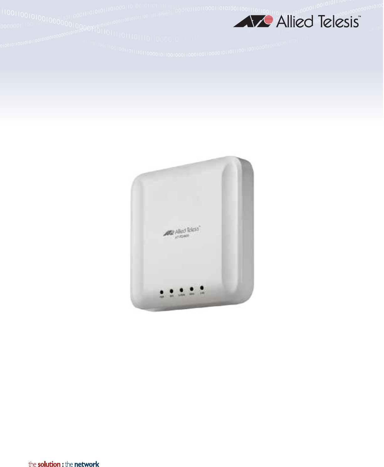
AT-AP500
Cloud-Managed Enterprise-class Wireless Access Point
with IEEE802.11a/b/g/n/ac Dual Radio
Installation Guide
Review Draft 4-25-16
Copyright 2016 Allied Telesis, Inc.
All rights reserved. No part of this publication may be reproduced without prior written permission from Allied Telesis, Inc.
Allied Telesis and the Allied Telesis logo are trademarks of Allied Telesis, Incorporated. All other product names, company names,
logos or other designations mentioned herein are trademarks or registered trademarks of their respective owners.
Allied Telesis, Inc. reserves the right to make changes in specifications and other information contained in this document without prior
written notice. The information provided herein is subject to change without notice. In no event shall Allied Telesis, Inc. be liable for
any incidental, special, indirect, or consequential damages whatsoever, including but not limited to lost profits, arising out of or related
to this manual or the information contained herein, even if Allied Telesis, Inc. has been advised of, known, or should have known, the
possibility of such damages.
Review Draft 4-25-16
3
Electrical Safety and Emissions
Standards
This product meets the following standards:
Federal Communications Commission Interference Statement
Declaration of Conformity
Manufacturer Name: Allied Telesis, Inc.
Declares that the product: Wireless access point with PoE+ powered device function
Model Number: AT-AP500
This device complies with Part 15 of the FCC Rules. Operation is subject to the following two
conditions: (1) This device may not cause harmful interference, and (2) this device must accept
any interference received, including interference that may cause undesired operation.
This equipment has been tested and found to comply with the limits for a Class B digital device,
pursuant to Part 15 of the FCC Rules. These limits are designed to provide reasonable protection
against harmful interference in a residential installation. This equipment generates, uses and can
radiate radio frequency energy and, if not installed and used in accordance with the instructions,
may cause harmful interference to radio communications. However, there is no guarantee that
interference will not occur in a particular installation. If this equipment does cause harmful
interference to radio or television reception, which can be determined by turning the equipment
off and on, the user is encouraged to try to correct the interference by one of the following
measures:
Reorient or relocate the receiving antenna.
Increase the separation between the equipment and receiver.
Connect the equipment into an outlet on a circuit different from that to which the receiver is
connected.
Consult the dealer or an experienced radio/TV technician for help.
Caution
FCC Caution: Any changes or modifications not expressly approved by the party responsible
for compliance could void the user's authority to operate this equipment. E80
Avertissement
Avertissement de la FCC: Les changements ou modifications non expressément approuvés
par la partie responsable de la conformité pourraient annuler l'autorité de l'utilisateur à utiliser
cet équipement. E80
Review Draft 4-25-16

4
This transmitter must not be co-located or operating in conjunction with any other antenna or
transmitter.
For operation within 5150-5250MHz / 5470-5725MHz frequency range, it is restricted to indoor
environment.The band from 5600-5650MHz will be disabled by the software during the manufacturing
and cannot be changed by the end user. This device meets all the other requirements specified in
Part 15E, Section 15.407 of the FCC Rules.
Radiation Exposure Statement:
This equipment complies with FCC radiation exposure limits set forth for an uncontrolled
environment. This equipment should be installed and operated with minimum distance 26cm
between the radiator & your body.
Safety and Electromagnetic Emissions Certificates
Electromagnetic Compatibility (EMC)
ICES-003 Class B
Radio Equipment
FCC 47 CFR Part 15, Subpart C
FCC 47 CFR Part 15, Subpart E
FCC OET Bulletin No. 65 Supplement C
RSS-Gen, Issue No. 4
RSS-102, Issue No. 5
RSS-247, Issue No. 1
Safety
UL 60950-1 2nd Edition
CAN/CSA C22.2 No. 60950-1
Translated Safety Statements
Important: The indicates that a translation of the safety statement is available in a PDF
document titled Translated Safety Statements on the Allied Telesis website at
www.alliedtelesis.com/support.
Review Draft 4-25-16

5
Contents
Preface ............................................................................................................................................................11
Safety Symbols Used in this Document..................................................................................................... 12
Contacting Allied Telesis............................................................................................................................ 13
Chapter 1: Overview ......................................................................................................................................15
Features..................................................................................................................................................... 16
Rear Panel Components............................................................................................................................ 17
LAN Port..................................................................................................................................................... 19
Power over Ethernet............................................................................................................................ 19
Connector Type ................................................................................................................................... 19
Speed .................................................................................................................................................. 19
Duplex Mode ....................................................................................................................................... 19
Maximum Distance .............................................................................................................................. 19
Cable Requirements............................................................................................................................ 19
Automatic MDIX Detection .................................................................................................................. 20
Port Pinouts ......................................................................................................................................... 20
LEDs .......................................................................................................................................................... 21
Reset Button .............................................................................................................................................. 22
Chapter 2: Installing the Access Point ........................................................................................................23
Reviewing Safety Precautions ................................................................................................................... 24
Unpacking the AT-AP500 Access Point..................................................................................................... 26
Installing the Access Point on a Wall or Ceiling......................................................................................... 27
Guidelines............................................................................................................................................ 27
Mounting the Base Plate to the Wall or Ceiling ................................................................................... 28
Attaching the Mounting Bracket to the Access Point........................................................................... 29
Attaching the Access Point to the Base Plate ..................................................................................... 30
Cabling the Access Point..................................................................................................................... 31
Kensington Lock......................................................................................................................................... 34
Starting the Initial Management Session on the Access Point................................................................... 35
Requirements ...................................................................................................................................... 35
Starting the Management Session ...................................................................................................... 35
Appendix A: Technical Specifications ........................................................................................................37
Physical Specifications............................................................................................................................... 37
Environmental Specifications..................................................................................................................... 37
Power Specifications.................................................................................................................................. 38
LAN Port..................................................................................................................................................... 39
Safety and Electromagnetic Emissions Certifications ................................................................................ 41
Appendix B: Regulatory Statements ...........................................................................................................43
Federal Communication Commission Interference Statement................................................................... 44
Review Draft 4-25-16
Contents
6
Review Draft 4-25-16

7
Figures
Figure 1: Rear Panel Components .................................................................................................................. 17
Figure 2: AT-TQ0091 AC/DC Power Adapter.................................................................................................. 26
Figure 3: Ventilation Slots................................................................................................................................ 27
Figure 4: Base Plate Hole Dimensions............................................................................................................ 28
Figure 5: Mounting Base Plate ........................................................................................................................ 28
Figure 6: Bottom of Access Point .................................................................................................................... 29
Figure 7: Locking Bracket to Access Point ...................................................................................................... 29
Figure 8: Attaching the Mounting-Bracket Screw ............................................................................................ 30
Figure 9: Attaching Access Point to Base Plate .............................................................................................. 30
Figure 10: Connecting the Network Cable....................................................................................................... 31
Figure 11: Connecting the Power Cable from the AT-TQ0091 AC/DC Adapter.............................................. 32
Figure 12: Removing an AC Plug from the AT-TQ0091 AC/DC Power Adapter ............................................. 32
Figure 13: Installing an AC Plug on the AT-TQ0091 AC/DC Power Adapter .................................................. 33
Figure 14: Kensington Lock............................................................................................................................. 34
Figure 15: Pin Layout for the RJ45 Connector on the LAN Port...................................................................... 39
Review Draft 4-25-16
List of Figures
8
Review Draft 4-25-16

9
Tables
Table 1. Components on the Rear Panel ....................................................................................................... 17
Table 2. Twisted Pair Cable for the LAN Port ................................................................................................. 20
Table 3. LEDs on the AT-AP500 Access Point .............................................................................................. 21
Table 4. AT-AP500 Physical Specifications ................................................................................................... 37
Table 5. Environmental Specifications ........................................................................................................... 37
Table 6. AT-AP500 Maximum Power Consumption ....................................................................................... 38
Table 7. AT-TQ0091 Power Adapter .............................................................................................................. 38
Table 8. LAN Port Specifications .................................................................................................................... 39
Table 9. MDI Pin Signals (10Base-T or 100Base-TX) .................................................................................... 39
Table 10. MDI-X Pin Signals (10Base-T or 100Base-TX) .............................................................................. 40
Table 11. 1000Base-T Connector Pinouts ..................................................................................................... 40
Table 12. Safety and Electromagnetic Emissions Certificates ....................................................................... 41
Review Draft 4-25-16
List of Tables
10
Review Draft 2-1-16


Preface
12
Safety Symbols Used in this Document
This document uses the following conventions.
Note
Notes provide additional information.
Caution
Cautions inform you that performing or omitting a specific action
may result in equipment damage or loss of data.
Warning
Warnings inform you that performing or omitting a specific action
may result in bodily injury.
Review Draft 2-1-16

AT-AP500 Wireless Access Point Installation Guide
13
Contacting Allied Telesis
If you need assistance with this product, you may contact Allied Telesis
technical support by going to the Support & Services section of the Allied
Telesis web site at www.alliedtelesis.com/support. You can find links for
the following services on this page:
24/7 Online Support — Enter our interactive support center to
search for answers to your product questions in our knowledge
database, check support tickets, learn about Return Merchandise
Authorizations (RMAs), and contact Allied Telesis technical
experts.
USA and EMEA phone support — Select the phone number that
best fits your location and customer type.
Hardware warranty information — Learn about Allied Telesis
warranties and register your product online.
Replacement Services — Submit an RMA request via our
interactive support center.
Documentation — View the most recent installation and user
guides, software release notes, white papers, and data sheets for
your products.
Software Downloads — Download the latest software releases for
your managed products.
For sales or corporate information, go to www.alliedtelesis.com/
purchase.
Review Draft 2-1-16
Preface
14
Review Draft 2-1-16


Chapter 1: Overview
16
Features
The main features of the product are listed here:
Dual concurrent radio: 2.4 GHz and 5 GHz
IEEE 802.11a/b/g/n/ac
MIMO with internal omni antennas
— 2.4 GHz radio: 3x3:3ss
— 5 GHz radio: 4x4:4ss
Maximum capacity 2.4 GHz: 450 Mbps
Maximum capacity 5 GHz: 2,200 Mbps
Rogue access point detection
Multiple SSIDs
One 10/100/1000Base-T Ethernet port with Auto-Negotiation, auto
MDI/MDIX, and IEEE 802.3at Power over Ethernet (PoE+)
IEEE 802.3 (10Base-T), IEEE 802.3u (100Base-TX), and IEEE
802.3ab (1000Base-T) compliance on the Ethernet port
MAC address filtering for wireless access security
Broadcast and multicast rate limiting
Virtual access points for multiple broadcast domains
DHCP client
WPA-Personal and WPA-Enterprise with WPA, WPA2, TKIP, and
CCMP (AES) authentication and encryption
Static WEP encryption
Cloud-managed from AlliedView™ Cloud
Quality of Service
Wall or ceiling installation
Review Draft 2-1-16
AT-AP500 Wireless Access Point Installation Guide
17
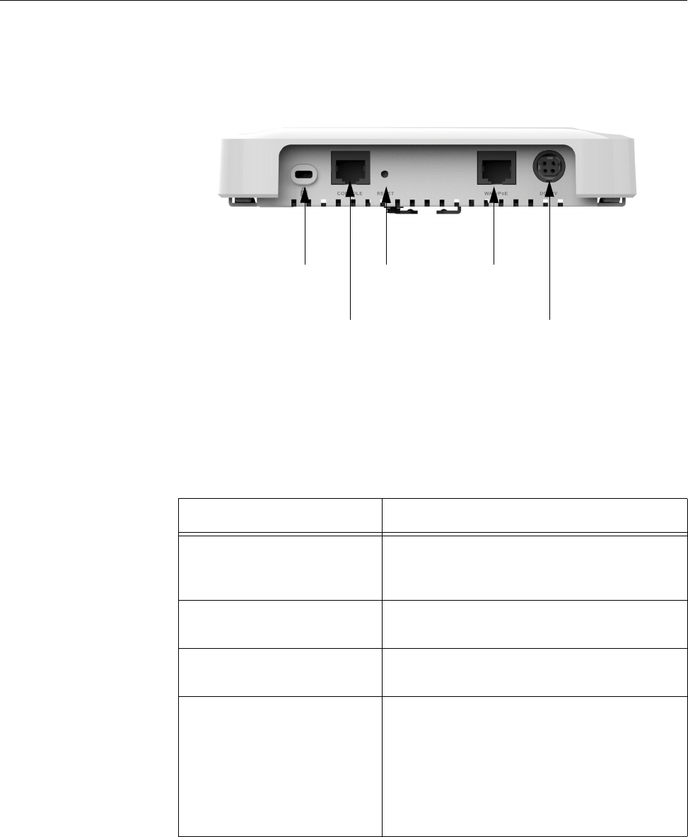
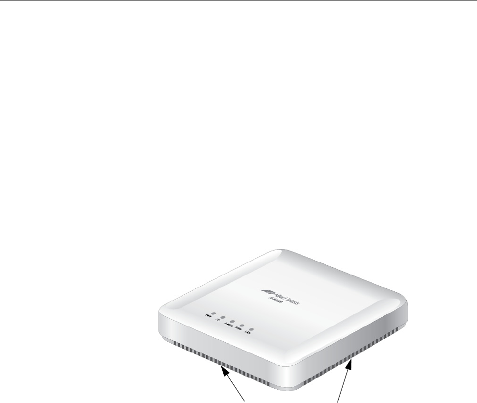
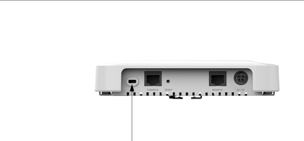
Rear Panel Components
The rear panel components of the AT-AP500 Access Point are illustrated
in Figure 1.
Figure 1. Rear Panel Components
The components are listed in Table 1.
Table 1. Components on the Rear Panel
Field Description
Kensington Lock Lock to secure the access point. For
information, refer to “Kensington Lock” on
page 34.
Console Port The Console port is for manufacturing
purposes only.
Reset Button Reboots the unit. For information, refer to
“Reset Button” on page 22.
LAN Port The LAN port connects the access point
to your wired network. It supports PoE+. If
you connect the port to an Ethernet switch
that supports PoE+, you do not have to
use the AC/DC adapter to power the
device. For information, refer to “LAN
Port” on page 19.
Reset
Button
Console
Port
Kensington
Lock
DC Power
Connector
LAN Port
Review Draft 2-1-16

Chapter 1: Overview
18
DC Power Connector This connector is for the AT-TQ0091
Power Adapter. The access point can be
powered with PoE+ on the LAN port or the
power adapter. The AT-TQ0091 Power
Adapter does not come with the access
point. It must be ordered separately from
Allied Telesis.
Table 1. Components on the Rear Panel (Continued)
Field Description
Review Draft 2-1-16

AT-AP500 Wireless Access Point Installation Guide
19
LAN Port
The LAN port is used to connect the device to your Local Area Network
(LAN), typically through an Ethernet switch.
Power over
Ethernet
The AT-AP500 Access Point supports Power over Ethernet (PoE+) on the
LAN port. The unit is a PoE+ class 4 powered device with a maximum
power consumption of 16 watts. When the port is connected to a PoE+
Ethernet switch, the unit receives its power over the network cable that
carries the network traffic. If you use the PoE+ feature, you do not need to
use the AC/DC power adapter that has to be purchased separately.
Connector Type The LAN port has an eight-pin RJ45 connector. The port uses four pins at
10 or 100 Mbps and all eight pins at 1000 Mbps. The pin assignments are
listed in “LAN Port” on page 39.
Speed The LAN port can operate at 10, 100, or 1000 Mbps. The speed is set
automatically with Auto-Negotiation. You cannot disable Auto-Negotiation
on the port.
Note
The LAN port should be connected to a network device that also
adjusts its speed with Auto-Negotiation. If the network device does
not support Auto-Negotiation, the LAN port operates at 10 Mbps,
which may reduce network performance.
Duplex Mode The LAN port can operate in either half- or full-duplex mode at 10 or 100
Mbps, and full-duplex mode at 1000 Mbps. The port is IEEE 802.3u-
compliant and uses Auto-Negotiation to set the duplex mode. (You cannot
disable Auto-Negotiation on the port.)
Note
The LAN port should be connected to a network device that also
sets its duplex mode with Auto-Negotiation. If the network device
does not support Auto-Negotiation, the LAN port operates at half-
duplex mode. This may result in a duplex mode mismatch if the
network device is operating at full-duplex.
Maximum
Distance
The LAN port has a maximum operating distance of 100 meters (328 feet).
Cable
Requirements
The cable requirements for the LAN port are listed in Table 2 on page 20.
Review Draft 2-1-16

Chapter 1: Overview
20
Automatic MDIX
Detection
The 10/100/1000 Mbps twisted-pair port is IEEE 802.3ab compliant and
features automatic MDIX detection when operating at 10 or 100 Mbps.
(Automatic MDIX detection does not apply to 1000 Mbps.) This feature
automatically configures the port to MDI or MDI-X, depending on the
wiring configuration of the port on the Ethernet switch.
You may not disable automatic MDIX detection. For automatic MDIX
detection to work properly, it must also be present on the Ethernet switch.
The LAN port defaults to MDIX if it is connected to a network device that
does not support automatic MDIX detection.
Port Pinouts Refer to Table 9 on page 39 for the port pinouts of the LAN port when it is
operating at 10 or 100 Mbps in the MDI configuration and Table 10 on
page 40 for the MDI-X configuration. Refer to Table 11 on page 40 for the
port pinouts when the port is operating at 1000 Mbps.
Table 2. Twisted Pair Cable for the LAN Port
Cable Type
10Mbps 100Mbps 1000Mbps
Non-
PoE+ PoE+ Non-
PoE+ PoE+ Non-
PoE+ PoE+
Standard TIA/EIA 568-
B-compliant Category 3
shielded or unshielded
cabling with 100 ohm
impedance and 16 MHz
frequency.
YesNoNoNoNoNo
Standard TIA/EIA 568-
A-compliant Category 5
shielded or unshielded
cabling with 100 ohm
impedance and 100
MHz frequency.
Yes Yes Yes Yes No No
Standard TIA/EIA 568-
B-compliant Enhanced
Category 5 (Cat 5e)
shielded or unshielded
cabling with 100 ohm
impedance and 100
MHz frequency.
Yes Yes Yes Yes Yes Yes
Standard TIA/EIA 568-
B-compliant Category 6
or 6a shielded cabling.
Yes Yes Yes Yes Yes Yes
Review Draft 2-1-16

AT-AP500 Wireless Access Point Installation Guide
21
LEDs
The LEDs on the AT-AP500 Access Point are described in Table 3.
Table 3. LEDs on the AT-AP500 Access Point
LED State Description
PWR Solid Green The unit is receiving DC power that is
within the normal operating range.
Off The power supply is not receiving power
from either the AC/DC power adapter or a
PoE+ Ethernet switch.
SYS Solid Amber The access point is loading its firmware or
there is a system fault.
Off The unit is operating normally.
LAN Solid Green The Ethernet port is operating at 1000
Mbps.
Flashing
Green
The Ethernet port is operating at 1000
Mbps with link activity.
Solid Amber The Ethernet port is operating at 10/100
Mbps.
Flashing
Amber
The Ethernet port is operating at 10/100
Mbps with link activity.
2.4GHz Solid Green The 2.4GHz radio is sending and receiving
radio waves.
5GHz Solid Green The 5GHz radio is sending and receiving
radio waves.
Review Draft 2-1-16

Chapter 1: Overview
22
Reset Button
The Reset button on the rear panel is used to reboot the unit.
The Reset button is recessed to prevent it from being accidentally
pressed. To press the button, use a pointed object, such as the end of a
straightened paper clip.
Review Draft 2-1-16

23
Chapter 2
Installing the Access Point
This chapter describes how to install the AT-AP500 Wireless Access
Point. This chapter contains the following sections:
“Reviewing Safety Precautions” on page 24
“Unpacking the AT-AP500 Access Point” on page 26
“Installing the Access Point on a Wall or Ceiling” on page 27
“Kensington Lock” on page 34
“Starting the Initial Management Session on the Access Point” on
page 35
Review Draft 2-1-16

Chapter 2: Installing the Access Point
24
Reviewing Safety Precautions
Please review the following safety precautions before you begin to install
the access point.
Note
The indicates that a translation of the safety statement is
available in a PDF document titled Translated Safety Statements on
the Allied Telesis website at www.alliedtelesis.com/support.
Warning
To prevent electric shock, do not remove the cover. No user-
serviceable parts inside. This unit contains hazardous voltages and
should only be opened by a trained and qualified technician. To
avoid the possibility of electric shock, disconnect electric power to
the product before connecting or disconnecting the LAN cables.
E1
Warning
Do not work on equipment or cables during periods of lightning
activity. E2
Warning
Power cord is used as a disconnection device. To de-energize
equipment, disconnect the power cord. E3
Note
Pluggable Equipment. The socket outlet shall be installed near the
equipment and shall be easily accessible. E5
Caution
Air vents must not be blocked and must have free access to the
room ambient air for cooling. E6
Review Draft 2-1-16

AT-AP500 Wireless Access Point Installation Guide
25
Warning
Operating Temperature. This product is designed for a maximum
ambient temperature of 40°C E7.
Warning
To reduce the risk of electric shock, the PoE port on this product
must not connect to cabling that is routed outside the building where
this device is located. E40
Caution
FCC Caution: Any changes or modifications not expressly approved
by the party responsible for compliance could void the user's
authority to operate this equipment. E80
Warning
This equipment is intended for indoor use only. E95
Note
All Countries: Install product in accordance with local and National
Electrical Codes. E8
Note
This product is not approved for use in a computer room as defined
in the Standard for Protection of Electronic Computer/Data
Processing Equipment, ANSI/NFPA 75.
Note
If you are not using PoE to power to unit, use only an approved AC/
DC adapter.
Note
You should verify that your PoE network adheres to the standards of
a separated extra-low voltage (SELV) circuit before using the PoE
feature on the wireless access point.
Review Draft 2-1-16
Chapter 2: Installing the Access Point
26
Unpacking the AT-AP500 Access Point
As you unpack the access point, check the shipping container for the
components the following items:
One AT-AP500 Wireless Access Point
One AT-AP500 Wireless Access Point Quick Installation Guide
One mounting-bracket screw
One bracket and one base plate for wall or ceiling mounting
If any item is missing or damaged, contact your Allied Telesis sales
representative for assistance.
If you are not using the PoE feature on the LAN port of the access point to
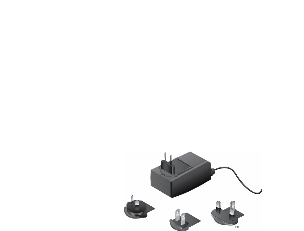
power the device, you need to separately order the AT-TQ0091 AC/DC
Power Adapter. The adapter comes with four regional AC plugs. (One of
the AC plugs comes pre-installed on the adapter.) Refer to Figure 2.
Figure 2. AT-TQ0091 AC/DC Power Adapter
Go to “Installing the Access Point on a Wall or Ceiling” on page 27.
Review Draft 2-1-16
AT-AP500 Wireless Access Point Installation Guide
27
Installing the Access Point on a Wall or Ceiling
This procedure contains the following sections.
“Guidelines”
“Mounting the Base Plate to the Wall or Ceiling” on page 28
“Attaching the Mounting Bracket to the Access Point” on page 29
“Attaching the Access Point to the Base Plate” on page 30
“Cabling the Access Point” on page 31
Guidelines Please review the following guidelines before installing the access point on
a wall or ceiling:
The selected location must not block the ventilation slots around
the base of the unit. Refer to Figure 3.
Figure 3. Ventilation Slots
The wall or ceiling mounting surface must be of proper material to
accommodate the self-tapping screws, such as wood strong
enough to support the weight of the equipment and cables.
Otherwise, you must provide anchors to fit the mounting surface.
One mounting-bracket screw is provided for attaching the
mounting bracket to the unit. You must provide the four self-
tapping screws that secure the base plate to the wall or ceiling.
The location must have an AC power source if you are using the
AT-TQ0091 Power Adapter.
Ventilation Slots
Review Draft 2-1-16
Chapter 2: Installing the Access Point
28
Mounting the
Base Plate to the
Wall or Ceiling
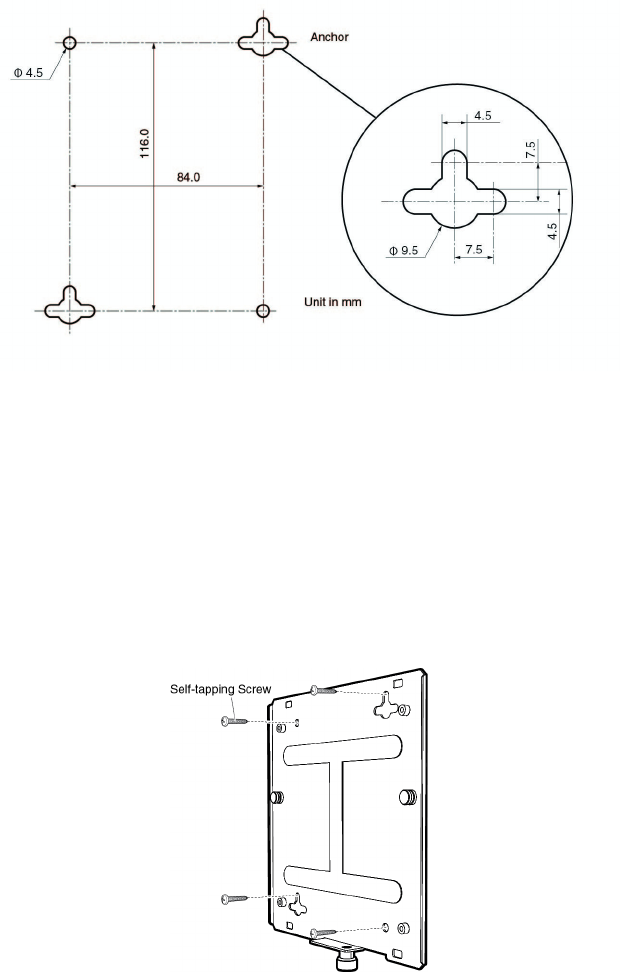
To mount the base plate to the wall or ceiling, perform the following:
1. Using the base plate as a template, mark the four holes for mounting
the base plate to the wall or ceiling. See Figure 4 for hole dimensions.
Figure 4. Base Plate Hole Dimensions
2. Drill the holes for the four self-tapping screws, and if applicable, two
wall anchors.
3. If you are not installing wall anchors, skip to Step 4. If so, install the
wall anchors.
4. Mount the base plate to the wall or ceiling using the self-tapping
screws, as shown in Figure 5.
Figure 5. Mounting Base Plate
Review Draft 2-1-16
AT-AP500 Wireless Access Point Installation Guide
29
Attaching the
Mounting
Bracket to the
Access Point
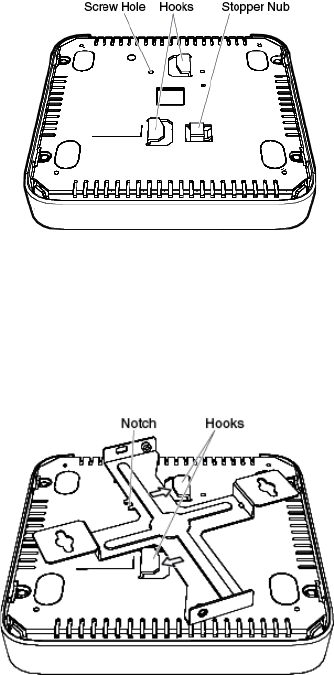
To attach the mounting bracket to the access point, perform the following:
1. Place the access point upside down on a flat surface.
2. Place the bracket against the bottom of the access point and use the
bracket to push downward on the stopper nub (see Figure 6).
Figure 6. Bottom of Access Point
3. Turn the bracket in the direction of the arrows shown in Figure 7 until
the two hooks hold the bracket: The stopper nub pops up, and the
bracket locks in place.
Figure 7. Locking Bracket to Access Point
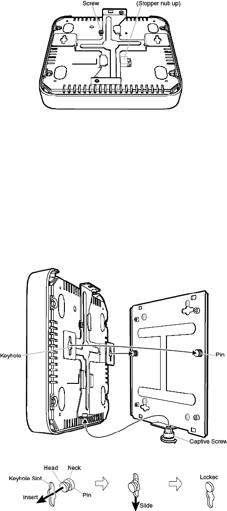
4. Attach the mounting-bracket screw through the notch in the mounting
bracket to the access point, as shown in Figure 8 on page 30: The
bracket is fastened to the access point.
Review Draft 2-1-16
Chapter 2: Installing the Access Point
30
Figure 8. Attaching the Mounting-Bracket Screw
Attaching the
Access Point to
the Base Plate
To attach the access point and mounting bracket to the base plate on the
wall or ceiling, perform the following:
1. Have someone hold the bottom of the access point next to the base
plate attached to the wall or ceiling.
2. Insert the two base-plate pins into the circles of the keyhole slots, as
shown in Figure 9.
Figure 9. Attaching Access Point to Base Plate
3. Slide the access point downward to lock the necks of the base-plate
pins in the slots, as shown in Figure 9.
Step 2 Step 3
Step 4
Step 3
Review Draft 2-1-16
AT-AP500 Wireless Access Point Installation Guide
31
4. Fasten the access point to the base plate by turning the base-plate
captive screw clockwise using a Phillips-head screwdriver, as shown in
Figure 9 on page 30.
Cabling the
Access Point
To install cabling on the access point, perform the following:
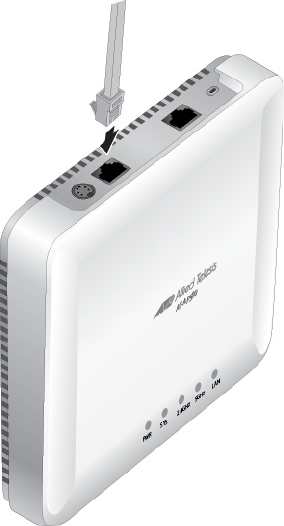
1. Connect a network cable to the LAN port (labeled WAN/PoE) on the
rear panel of the access point. Refer to Figure 10. The specifications of
the cable are listed in Table 2 on page 20.
Figure 10. Connecting the Network Cable
2. If you have not already done so, connect the other end of the network
cable to a port on an Ethernet switch.
3. Do one of the following:
If the access point is to be powered with the AT-TQ0091 AC/DC
Power Adapter, continue with this procedure to attach the power
adapter.
If the access point is to be powered with the PoE feature on the
LAN Port, the installation procedure is complete. Go to “Kensington
Lock” on page 34 or “Starting the Initial Management Session on
the Access Point” on page 35.
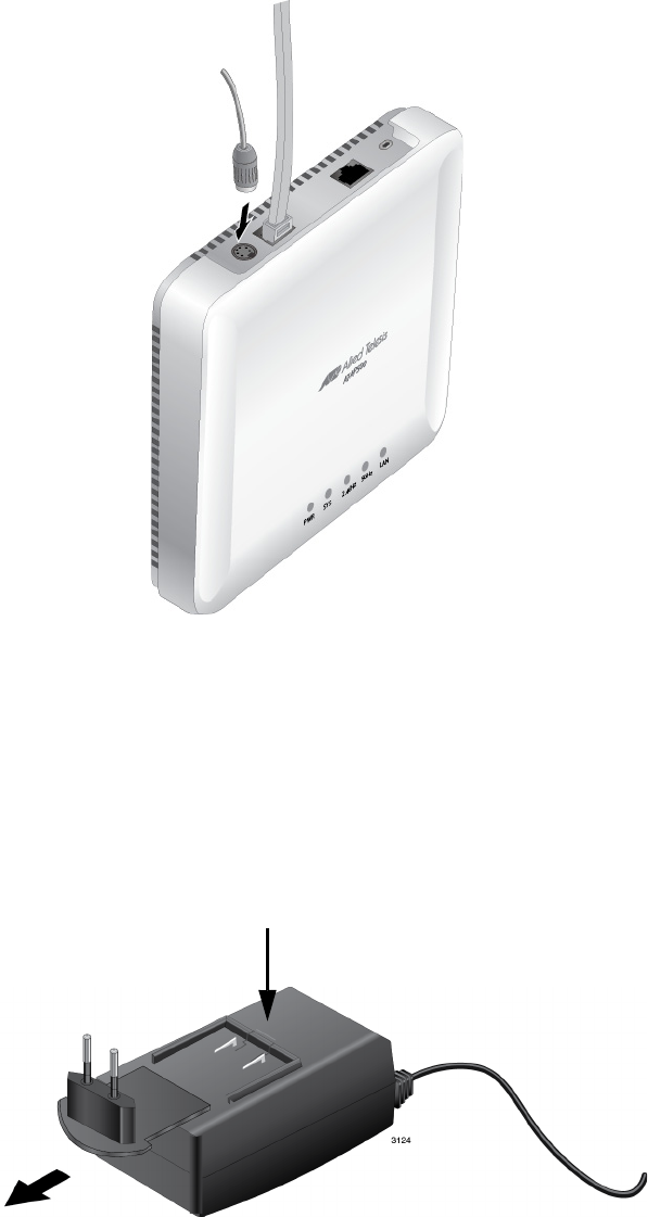
4. Connect the DC power cable from the AT-TQ0091 AC/DC Power
Adapter to the DC 12V connector on the rear panel of the access
point. Refer to Figure 11 on page 32.
Review Draft 2-1-16
Chapter 2: Installing the Access Point
32
Figure 11. Connecting the Power Cable from the AT-TQ0091 AC/DC
Adapter
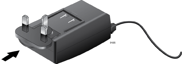
5. Check the AC plug on the AC/DC Power Adapter to see if it is the
correct plug for your region. If it is not the correct plug, remove it by
pushing down on the release tab and sliding it from the slot on the
adapter. Refer to Figure 12.
Figure 12. Removing an AC Plug from the AT-TQ0091 AC/DC Power
Adapter
Release Tab
Review Draft 2-1-16
AT-AP500 Wireless Access Point Installation Guide
33
6. Slide the correct AC plug for your region into the slot on the adapter
until it clicks into place. Refer to Figure 13.
Figure 13. Installing an AC Plug on the AT-TQ0091 AC/DC Power Adapter
7. Connect the AC plug on the power cord to an appropriate AC power
source. Refer to Table 7 on page 38 for the power specifications of the
power adapter.
After installing the access point on a wall or ceiling, go to “Kensington
Lock” on page 34 or “Starting the Initial Management Session on the
Access Point” on page 35.
Review Draft 2-1-16

AT-AP500 Wireless Access Point Installation Guide
35
Starting the Initial Management Session on the Access Point
This procedure contains the following sections.
“Requirements”
“Starting the Management Session”
Requirements You must have the following to initiate a management session on the
access point:
Network with a DHCP server and a route for the access point to the
Internet.
When you power on the access point for the first time, it will obtain
an IP address from the DHCP server, and then it must be able to
access the Internet to register itself with the AlliedView Cloud
service.
Serial number for the access point.
Starting the
Management
Session
To start the initial management session on the access point, perform the
following.
1. Create an AlliedView Cloud account at avcloud.alliedtelesis.com for
the management of the access points. Refer to the AlliedView Cloud
User’s Guide.
Note
This account will share the login credentials with the Allied Telesis
Support portal account.
2. Add one or more access points to the account by entering the access
point name and serial number. Refer to the AlliedView Cloud User’s
Guide.
3. If not done already, power on the access point: the access point
automatically registers with the AlliedView Cloud once a name and
serial number is assigned, and the unit is powered up.
4. Refer to the AlliedView Cloud User’s Guide to add the access point to
the network and configure the access point.
Review Draft 2-1-16
Chapter 2: Installing the Access Point
36
Review Draft 2-1-16

37
Appendix A
Technical Specifications
This appendix contains the following sections:
“Physical Specifications”
“Environmental Specifications”
“Power Specifications” on page 38
“LAN Port” on page 39
“Safety and Electromagnetic Emissions Certifications” on page 41
Physical Specifications
Environmental Specifications
Table 4. AT-AP500 Physical Specifications
Dimensions (W x D x H) 170.0 mm x 170.0 mm x 35.0 mm
(6.7 in. x 6.7 in. x 1.4 in.)
Weight 0.47 kg (1 lb.)
Table 5. Environmental Specifications
Operating Temperature of the
Access Point When Using PoE
0° C to 40° C (32° F to 104° F)
Operating Temperature of the
Access Point When Using the AC/
DC Adapter
0° C to 40° C (32° F to 104° F)
Storage Temperature -20° C to 60° C (-4° F to 140° F)
Operating Humidity 5% to 80% non-condensing
Storage Humidity 5% to 95% non-condensing
Review Draft 2-1-16

Appendix A: Technical Specifications
38
Power Specifications
Table 6. AT-AP500 Maximum Power Consumption
AT-AP500 16 watts
Table 7. AT-TQ0091 Power Adapter
Input Range 100~240 Vac
Input Frequency 47-63 Hz
Input Power Consumption (no load) <0.3W max.
Output Voltage +12 VDC
Output Current 2A max.
Review Draft 2-1-16
AT-AP500 Wireless Access Point Installation Guide
39
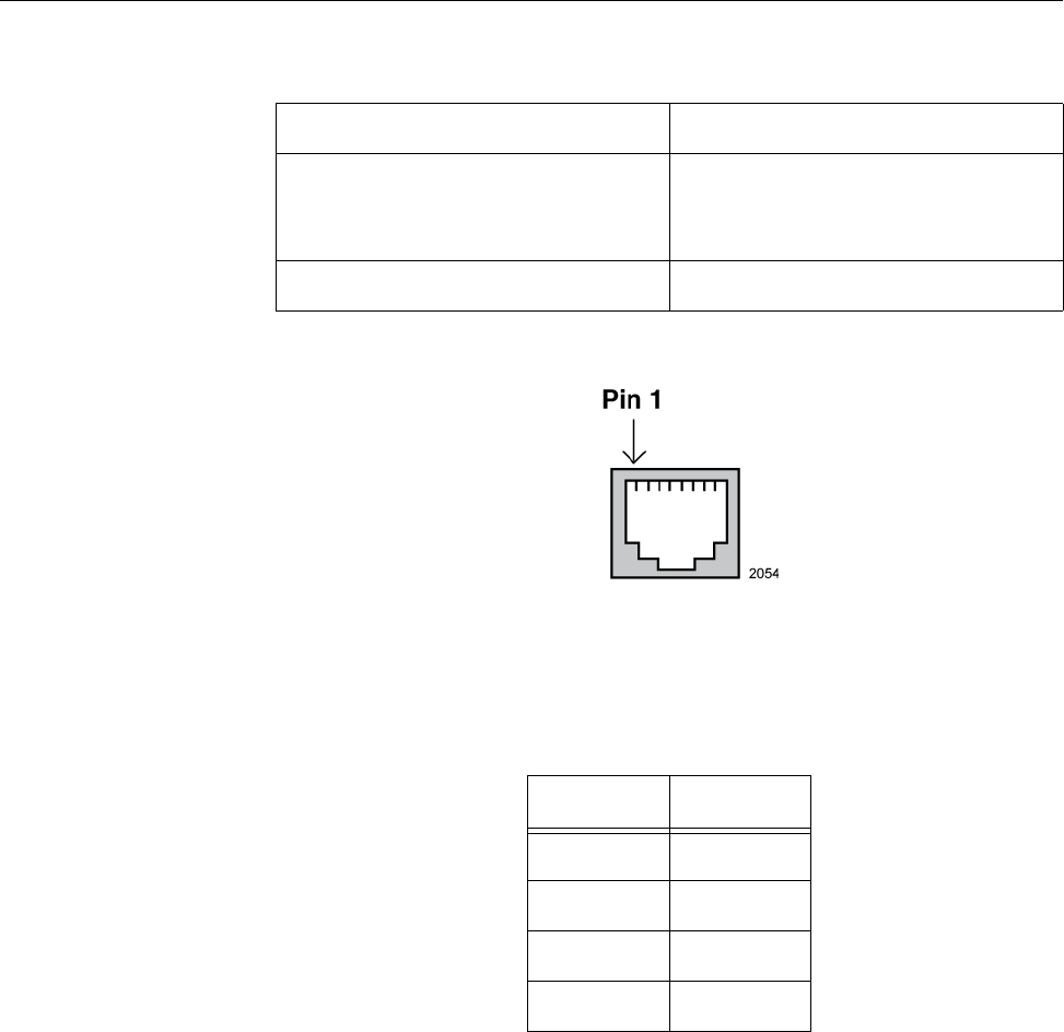
LAN Port
Figure 15 illustrates the pin layout of the LAN port.
Figure 15. Pin Layout for the RJ45 Connector on the LAN Port
Table 9 lists the pin signals when the port is operating in the MDI
configuration at 10 or 100 Mbps.
Table 8. LAN Port Specifications
Connector RJ45
Standards IEEE 802.3 (10Base-T)
IEEE 802.3u (100Base-TX)
IEEE 802.3ab (1000Base-T)
PoE standard IEEE 802.3at (class 4)
Table 9. MDI Pin Signals (10Base-T or 100Base-TX)
Pin Signal
1TX+
2TX-
3RX+
6RX-
Review Draft 2-1-16

Appendix A: Technical Specifications
40
Table 10 lists the pin signals for the MDI-X configuration at 10 or 100
Mbps.
Table 11 lists the pin signals when the LAN port is operating at 1000
Mbps.
Table 10. MDI-X Pin Signals (10Base-T or 100Base-TX)
Pin Signal
1RX+
2RX-
3TX+
6TX-
Table 11. 1000Base-T Connector Pinouts
Pin Pair Signal
1 1 TX and RX
2 1 TX and RX-
32TX and RX+
43TX and RX+
5 3 TX and RX-
6 2 TX and RX-
74TX and RX+
8 4 TX and RX-
Review Draft 2-1-16

AT-AP500 Wireless Access Point Installation Guide
41
Safety and Electromagnetic Emissions Certifications
Table 12. Safety and Electromagnetic Emissions Certificates
Electromagnetic
Compatibility (EMC)
FCC Class B
ICES-003 Class B
Radio Equipment FCC 47 CFR Part 15, Subpart C
FCC 47 CFR Part 15, Subpart E
FCC OET Bulletin No. 65 Supplement C
RSS-Gen, Issue No. 4
RSS-247, Issue No. 1
Safety UL 60950-1 2nd Edition
CAN/CSA C22.2 No. 60950-1
Review Draft 2-1-16
Appendix A: Technical Specifications
42
Review Draft 2-1-16


Appendix B: Regulatory Statements
44
Federal Communication Commission Interference Statement
This device complies with Part 15 of the FCC Rules. Operation is subject
to the following two conditions: (1) This device may not cause harmful
interference, and (2) this device must accept any interference received,
including interference that may cause undesired operation.
This equipment has been tested and found to comply with the limits for a
Class B digital device, pursuant to Part 15 of the FCC Rules. These limits
are designed to provide reasonable protection against harmful
interference in a residential installation. This equipment generates, uses
and can radiate radio frequency energy and, if not installed and used in
accordance with the instructions, may cause harmful interference to radio
communications. However, there is no guarantee that interference will not
occur in a particular installation. If this equipment does cause harmful
interference to radio or television reception, which can be determined by
turning the equipment off and on, the user is encouraged to try to correct
the interference by one of the following measures:
Reorient or relocate the receiving antenna.
Increase the separation between the equipment and receiver.
Connect the equipment into an outlet on a circuit different from that
to which the receiver is connected.
Consult the dealer or an experienced radio/TV technician for help.
Caution
FCC Caution: Any changes or modifications not expressly approved
by the party responsible for compliance could void the user's
authority to operate this equipment. E80
Caution
Avertissement de la FCC: Les changements ou modifications non
expressément approuvés par la partie responsable de la conformité
pourraient annuler l'autorité de l'utilisateur à utiliser cet équipement.
E80
This transmitter must not be co-located or operating in conjunction with
any other antenna or transmitter.
For operation within 5150-5250MHz / 5470-5725MHz frequency range,
it is restricted to indoor environment.The band from 5600-5650MHz will
be disabled by the software during the manufacturing and cannot be
changed by the end user. This device meets all the other requirements
specified in Part 15E, Section 15.407 of the FCC Rules.
Rdiaion Exposure Statement
This equipment complies with FCC radiation exposure limits set forth for
an uncontrolled environment. This equipment should be installed and
operated with minimum distance 26cm between the radiator & your body.
Review Draft 2-1-16

Appendix B: Regulatory Statements
45
Industry Canada Statement
This device complies with RSS-247 of the Industry Canada Rules.
Operation is subject to the following two conditions: (1) This device may
not cause harmful interference, and (2) this device must accept any
interference received, including interference that may cause undesired
operation.
Ce dispositif est conforme à la norme CNR-247 d'Industrie Canada
applicable aux appareils radio exempts de licence. Son fonctionnement
est sujet aux deux conditions suivantes: (1) le dispositif ne doit pas
produire de brouillage préjudiciable, et (2) ce dispositif doit accepter tout
brouillage reçu, y compris un brouillage susceptible de provoquer un
fonctionnement indésirable.
This Class B digital apparatus complies with Canadian ICES-003.
Cet appareil numérique de la Classe B est conforme à la norme NMB-003
du Canada.
Caution:
(i) the device for operation in the band 5150-5250 MHz is only for indoor
use to reduce the potential for harmful interference to co-channel mobile
satellite systems;
(ii) the maximum antenna gain permitted for devices in the bands 5250-
5350 MHz and 5470-5725 MHz shall comply with the e.i.r.p. limit; and
(iii) the maximum antenna gain permitted for devices in the band 5725-
5825 MHz shall comply with the e.i.r.p. limits specified for point-to-point
and non point-to-point operation as appropriate.
(iv) Users should also be advised that high-power radars are allocated as
primary users (i.e. priority users) of the bands 5250-5350 MHz and 5650-
5850 MHz and that these radars could cause interference and/or damage
to LE-LAN devices.
Avertissement:
Le guide d’utilisation des dispositifs pour réseaux locaux doit inclure des
instructions précises sur les restrictions susmentionnées, notamment:
(i) les dispositifs fonctionnant dans la bande 5 150-5 250 MHz sont
réservés uniquement pour une utilisation à l’intérieur afin de réduire les
risques de brouillage préjudiciable aux systèmes de satellites mobiles
utilisant les mêmes canaux;
Review Draft 3-24-16
46
(ii) le gain maximal d’antenne permis pour les dispositifs utilisant les
bandes 5 250-5 350 MHz et 5 470-5 725 MHz doit se conformer à la limite
de p.i.r.e.;
(iii) le gain maximal d’antenne permis (pour les dispositifs utilisant la
bande 5 725-5 825 MHz) doit se conformer à la limite de p.i.r.e. spécifiée
pour l’exploitation point à point et non point à point, selon le cas.
(iv) De plus, les utilisateurs devraient aussi être avisés que les utilisateurs
de radars de haute puissance sont désignés utilisateurs principaux (c.-à-
d., qu’ils ont la priorité) pour les bandes 5 250-5 350 MHz et 5 650-5 850
MHz et que ces radars pourraient causer du brouillage et/ou des
dommages aux dispositifs LAN-EL.
Radiation Exposure Statement:
This equipment complies with IC radiation exposure limits set forth for an
uncontrolled environment. This equipment should be installed and
operated with minimum distance 26cm between the radiator & your body.
Déclaration d'exposition aux radiations:
Cet équipement est conforme aux limites d'exposition aux rayonnements
IC établies pour un environnement non contrôlé. Cet équipement doit être
installé et utilisé avec un minimum de 26cm de distance entre la source
de rayonnement et votre corps.
Review Draft 3-24-16