Allied Telesis K K MWS2533AP IEEE 802.a/b/g/n/ac Managed Wireless Access Point User Manual at002418a
Allied Telesis K.K. IEEE 802.a/b/g/n/ac Managed Wireless Access Point at002418a
UserManual.wiki
>
Allied Telesis K K
>
MWS2533AP User Manual
Users Manual
Navigation menu
Upload a User Manual
Namespaces
Wiki Guide
HTML
PDF
Info
Views
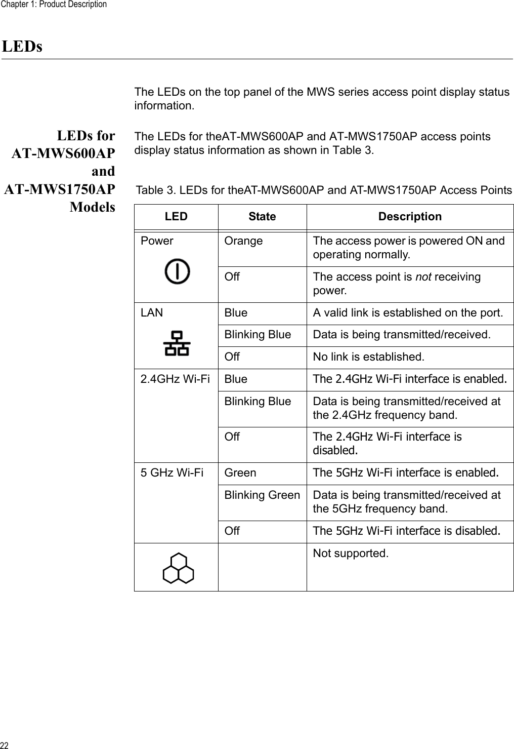
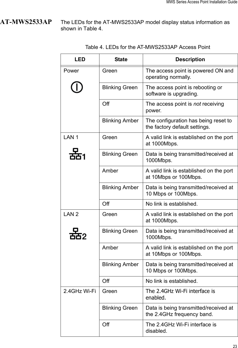
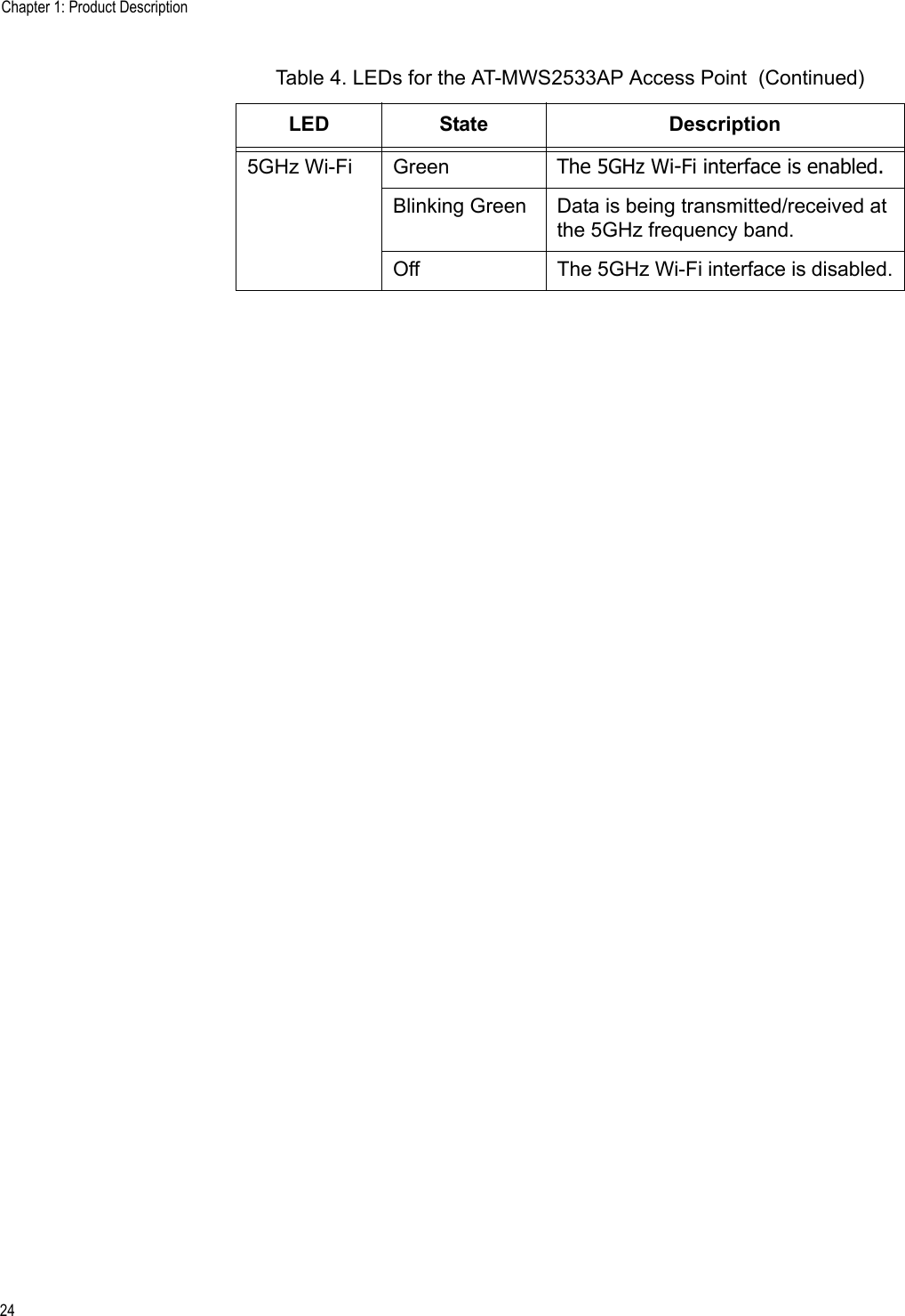
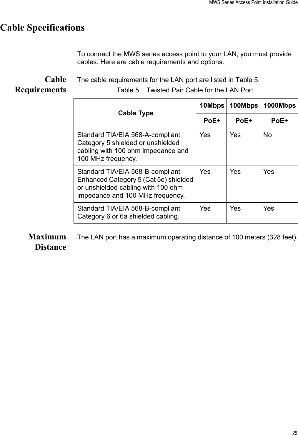
User Manual
Discussion / Help
Navigation