Allied Telesis K K TQ3600 Wireless access point with PoE powered device function User Manual at001863a
Allied Telesis K.K. Wireless access point with PoE powered device function at001863a
Contents
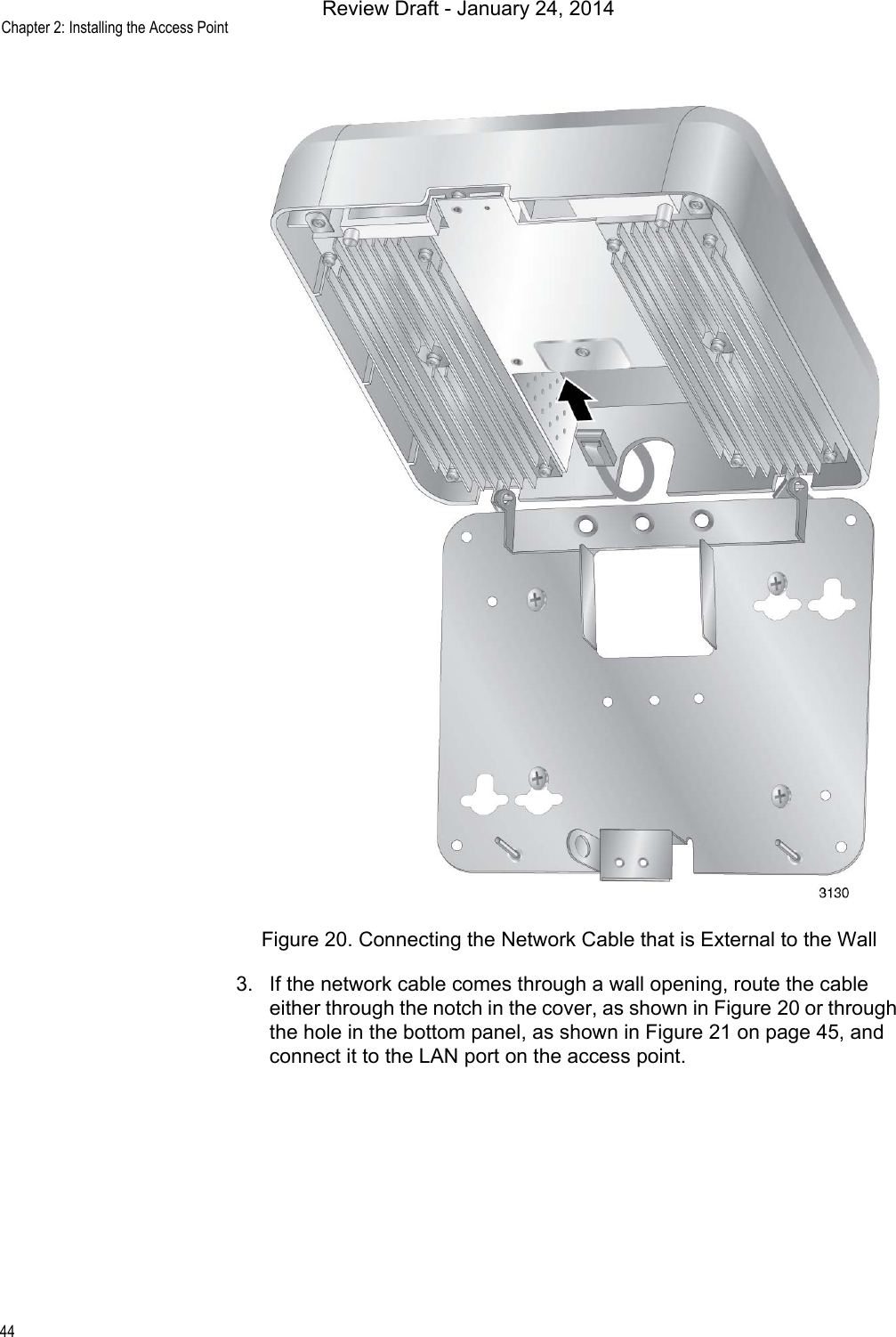
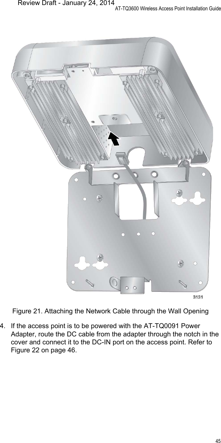
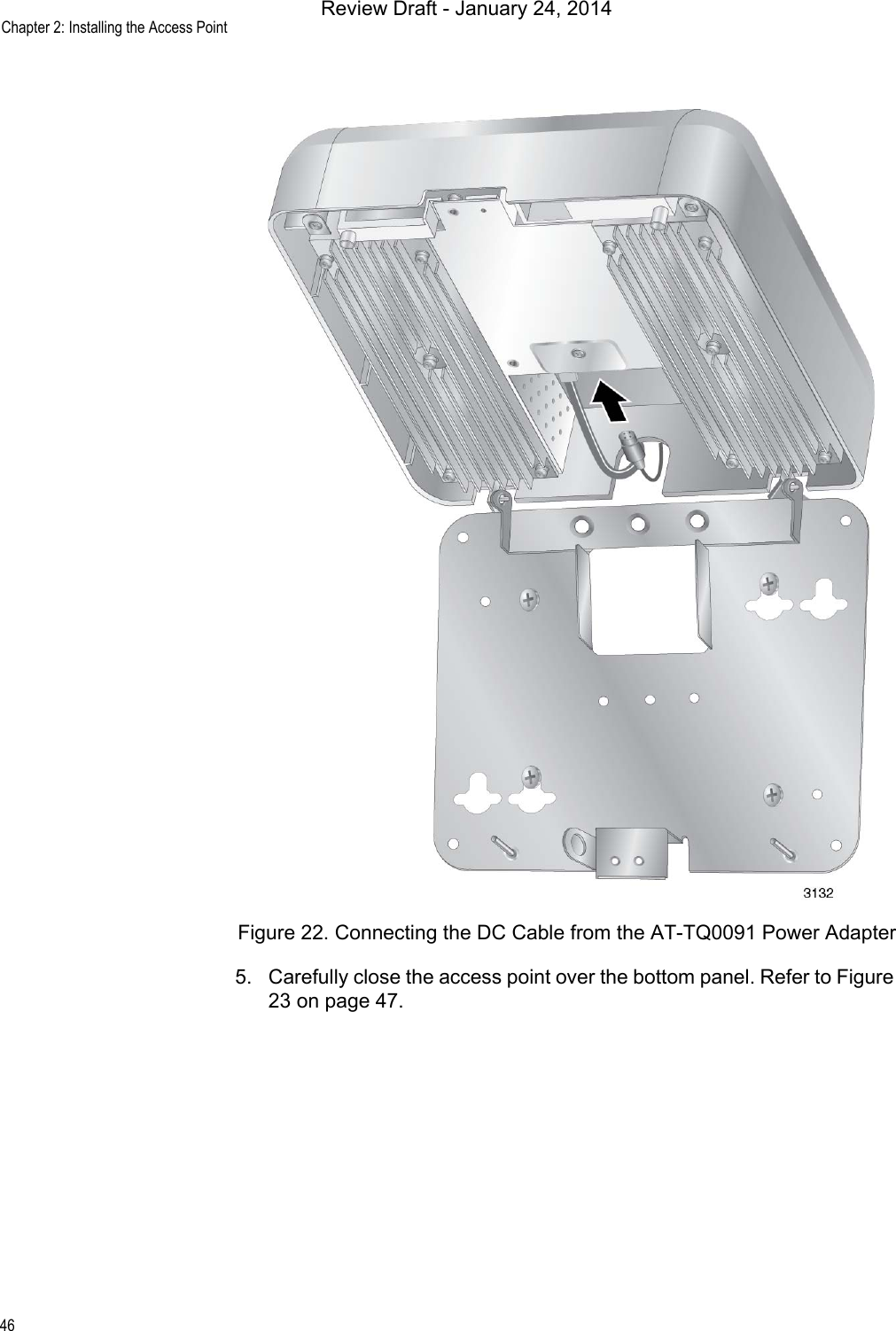
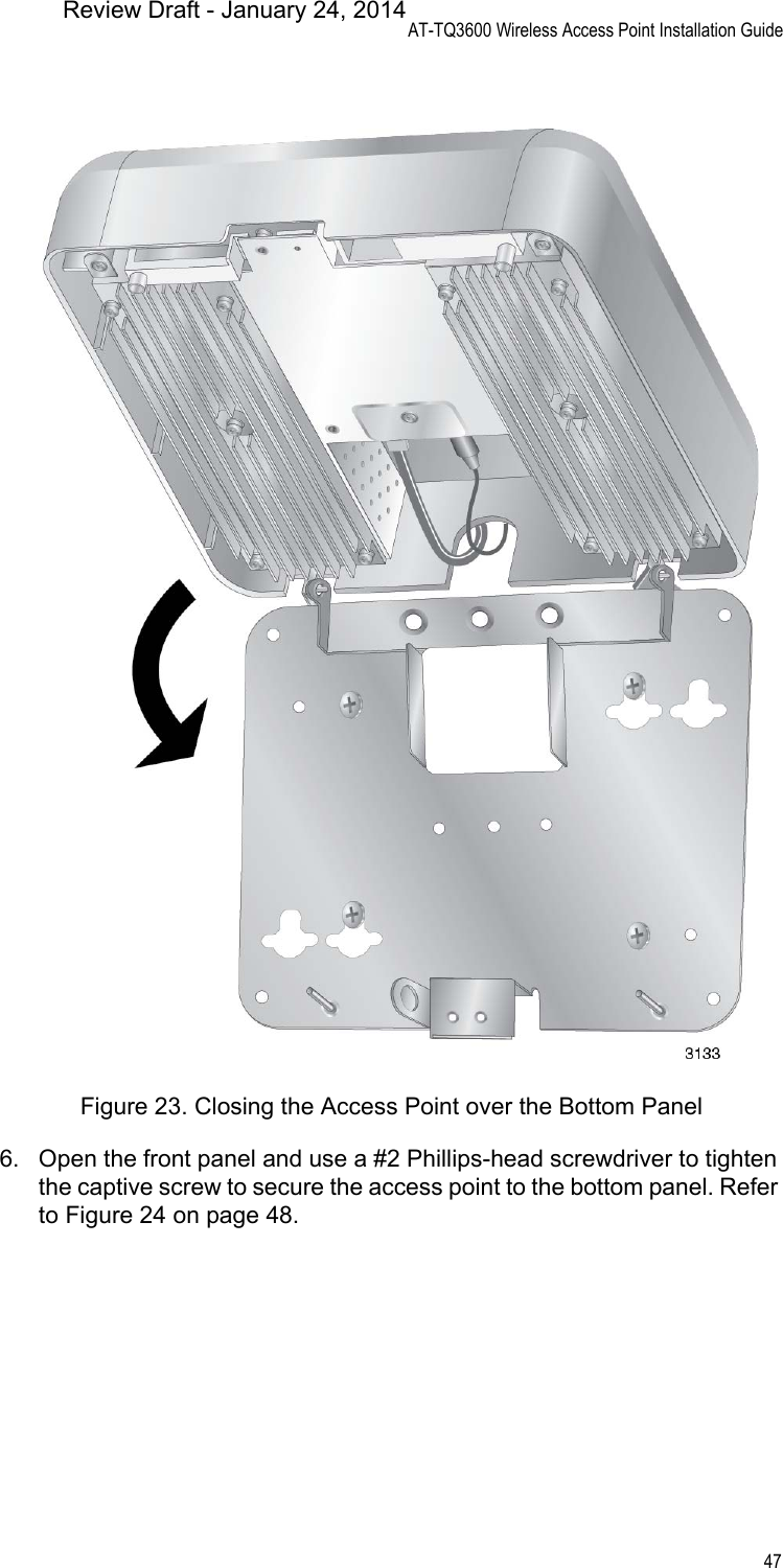
- 1. User manual (statement)
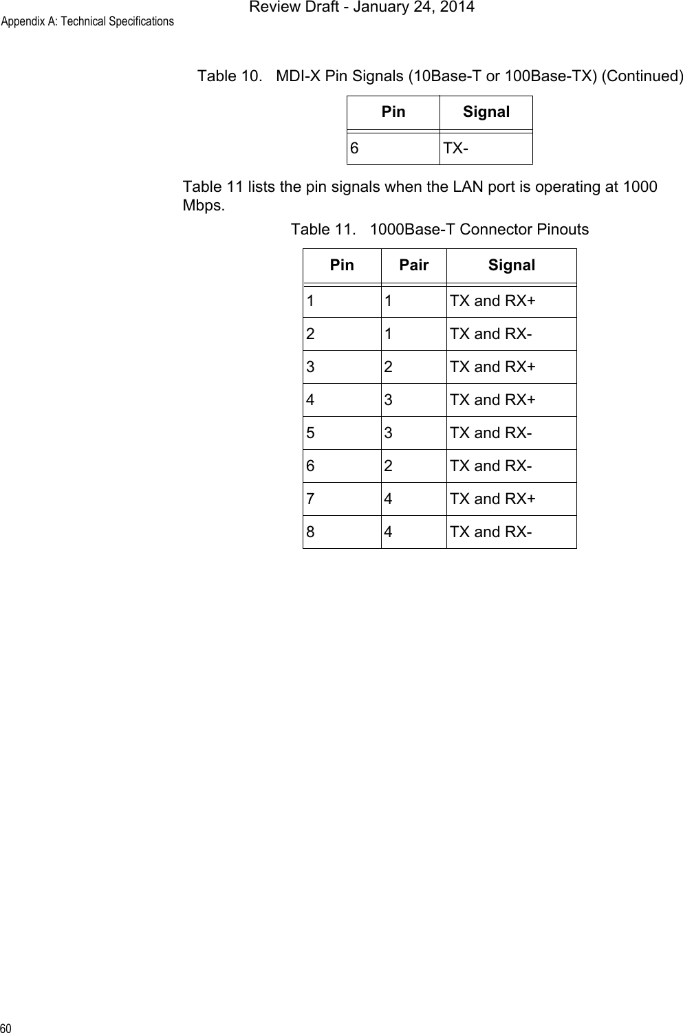
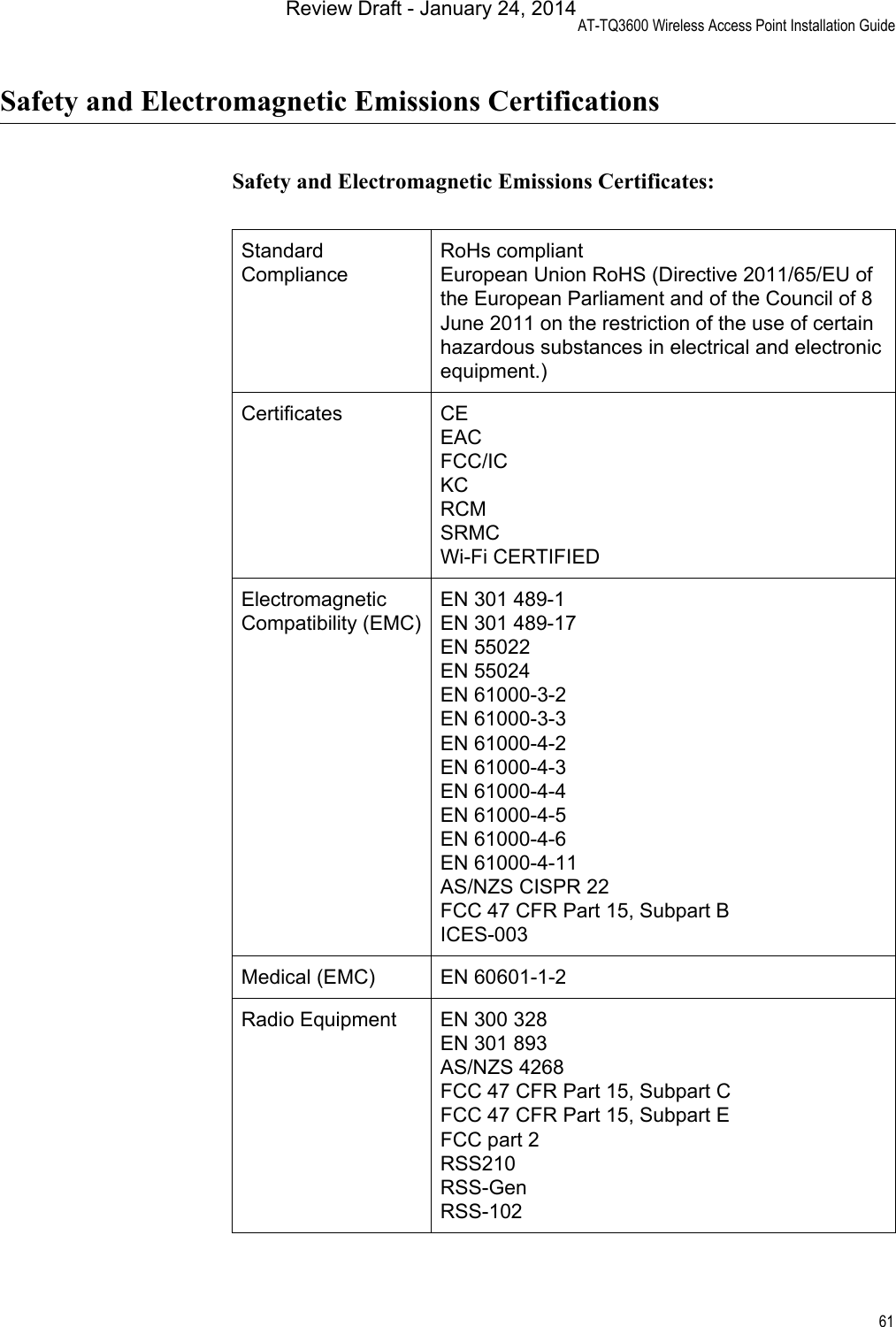
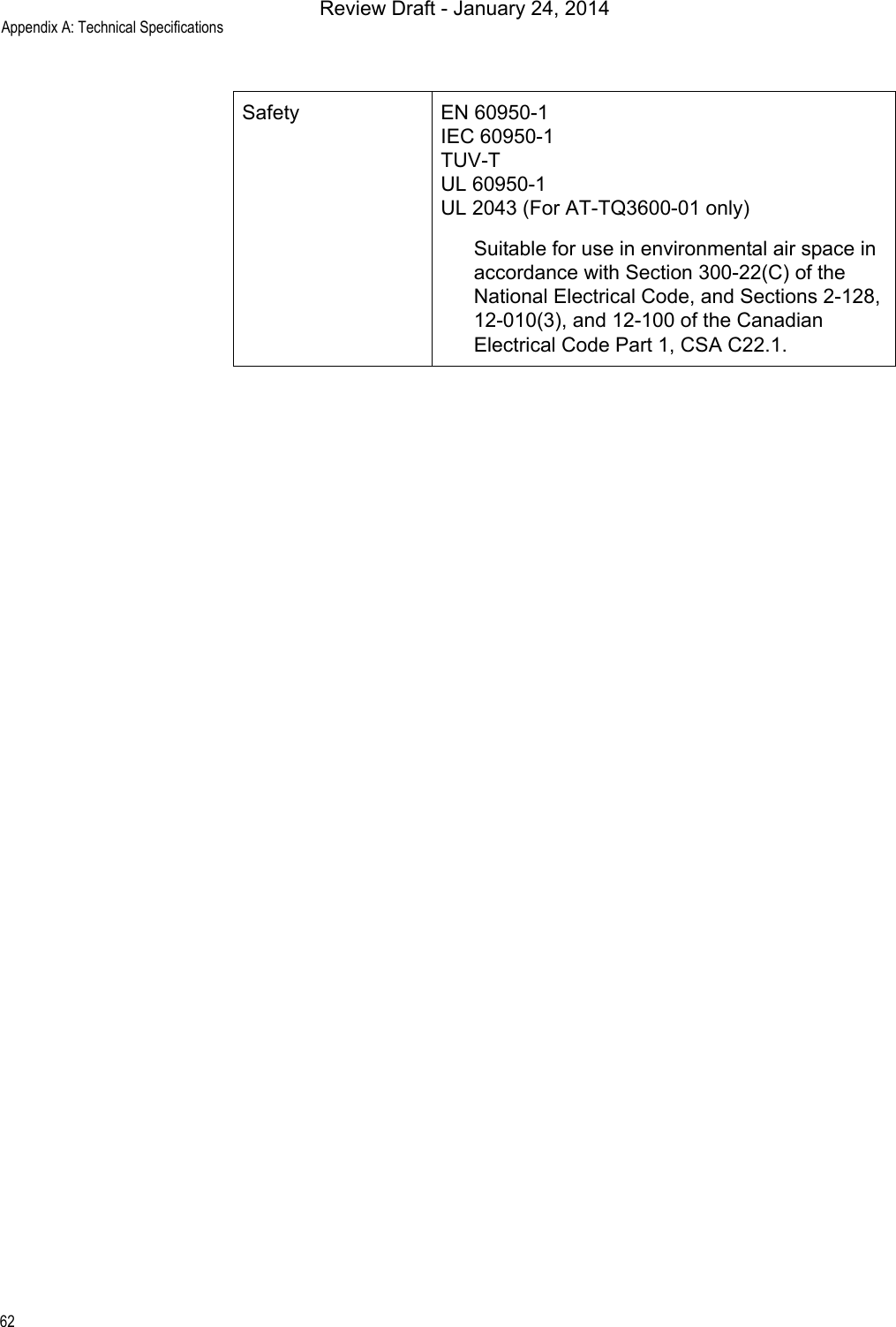
- 2. User manual
- 3. User Manual_rev 2
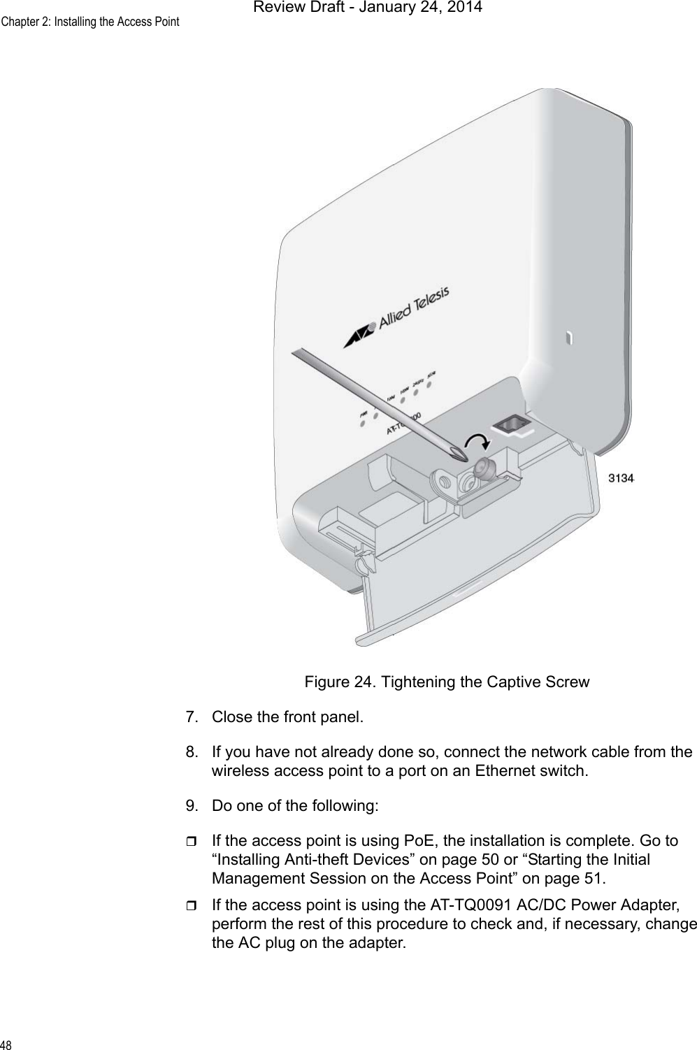
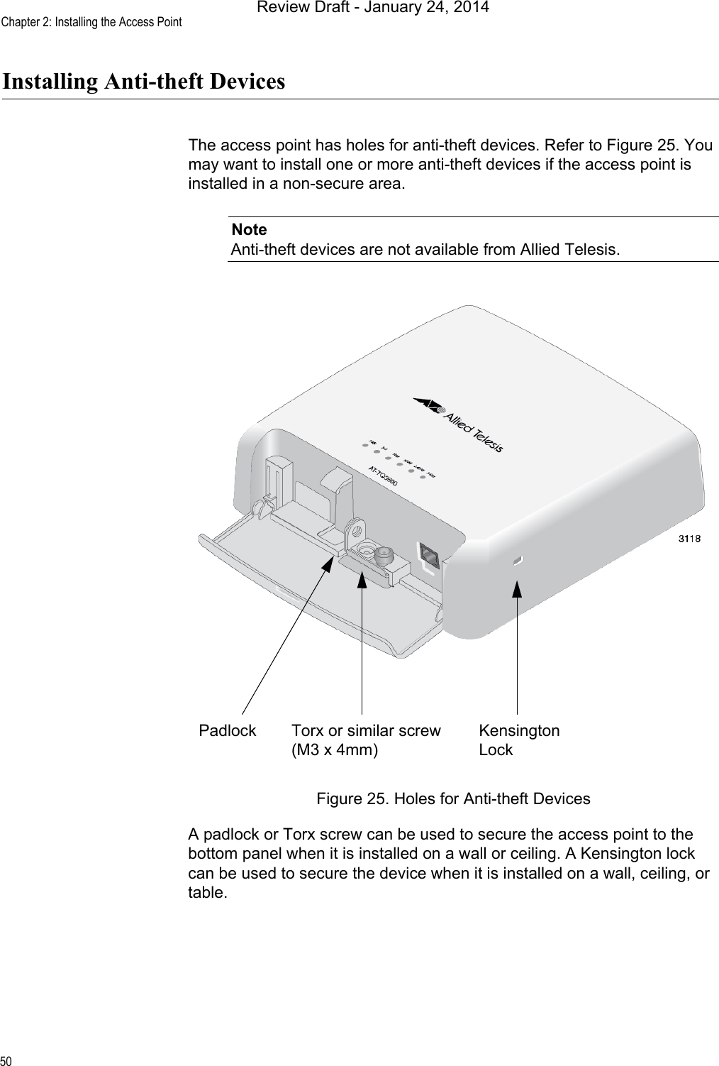
User manual
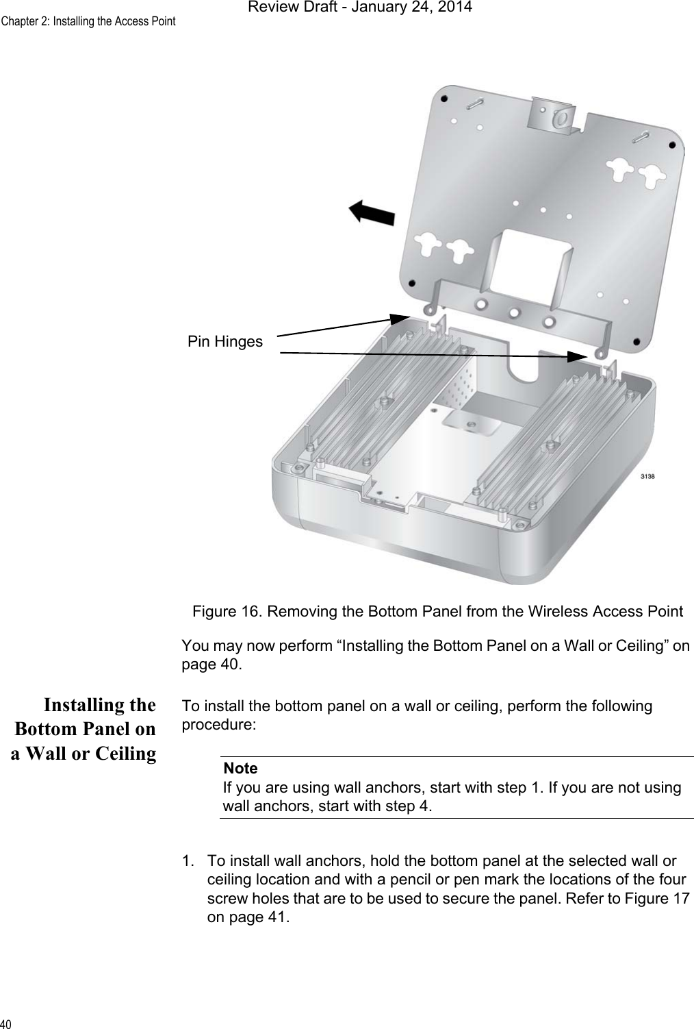
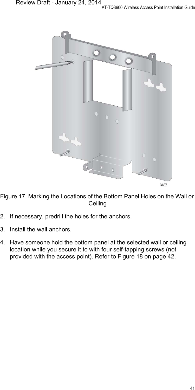
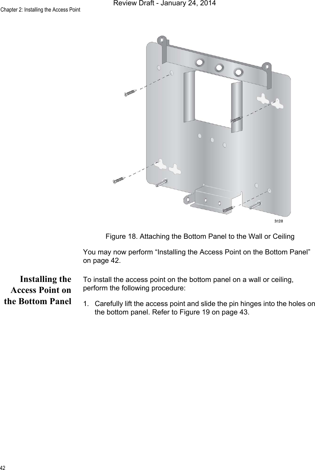
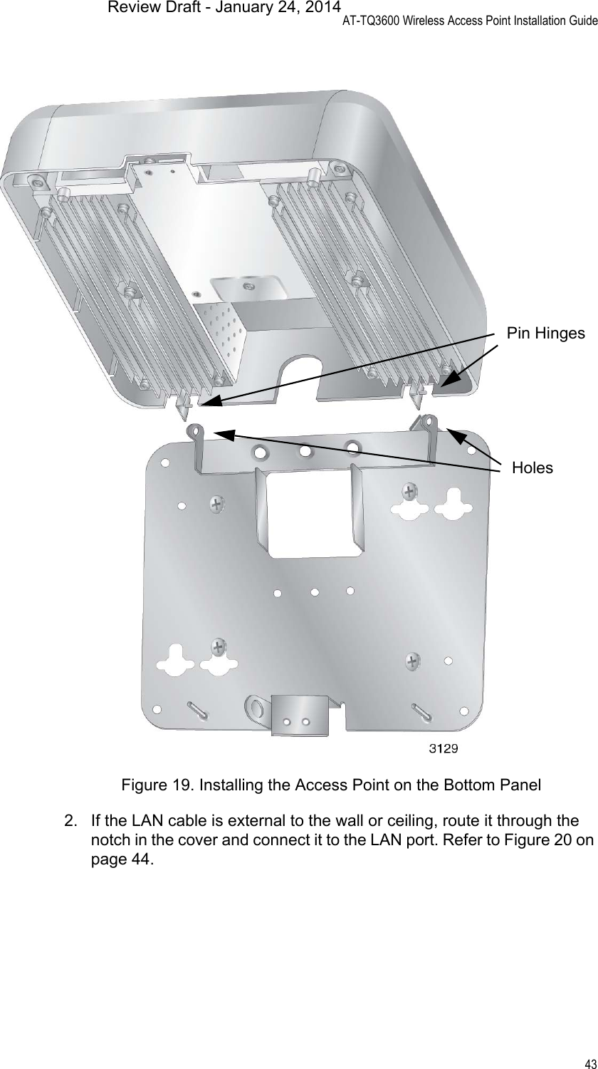
![Copyright 2014 Allied Telesis, Inc.All rights reserved.This product includes software licensed under the BSD License. As such, the following language applies for those portions of the software licensed under the BSD License:Redistribution and use in source and binary forms, with or without modification, are permitted provided that the following conditions are met:* Redistributions of source code must retain the above copyright notice, this list of conditions and the following disclaimer.* Redistributions in binary form must reproduce the above copyright notice, this list of conditions and the following disclaimer in the documentation and/or other materials provided with the distribution.* Neither the name of Allied Telesis, Inc. nor the names of the respective companies above may be used to endorse or promote products derived from this software without specific prior written permission.THIS SOFTWARE IS PROVIDED BY THE COPYRIGHT HOLDERS AND CONTRIBUTORS "AS IS" AND ANY EXPRESS OR IMPLIED WARRANTIES, INCLUDING, BUT NOT LIMITED TO, THE IMPLIED WARRANTIES OF MERCHANTABILITY AND FITNESS FOR A PARTICULAR PURPOSE ARE DISCLAIMED. IN NO EVENT SHALL THE COPYRIGHT HOLDER OR CONTRIBUTORS BE LIABLE FOR ANY DIRECT, INDIRECT, INCIDENTAL, SPECIAL, EXEMPLARY, OR CONSEQUENTIAL DAMAGES (INCLUDING, BUT NOT LIMITED TO, PROCUREMENT OF SUBSTITUTE GOODS OR SERVICES; LOSS OF USE, DATA, OR PROFITS; OR BUSINESS INTERRUPTION) HOWEVER CAUSED AND ON ANY THEORY OF LIABILITY, WHETHER IN CONTRACT, STRICT LIABILITY, OR TORT (INCLUDING NEGLIGENCE OR OTHERWISE) ARISING IN ANY WAY OUT OF THE USE OF THIS SOFTWARE, EVEN IF ADVISED OF THE POSSIBILITY OF SUCH DAMAGE.Copyright (c) [dates as appropriate to package] by The Regents of the University of California - All rights reserved. Copyright (c) 2000-2003 by Intel Corporation - All rights reserved. Copyright (c) 1997-2003, 2004 by Thomas E. Dickey <dickey@invisible-island.net> - All rights reserved. Copyright (c) 2001-2009 by Brandon Long (ClearSilver is now licensed under the New BSD License.) Copyright (c) 1984-2000 by Carnegie Mellon University - All rights reserved. Copyright (c) 2002,2003 by Matt Johnston - All rights reserved. Copyright (c) 1995 by Tatu Ylonen <ylo@cs.hut.fi> - All rights reserved. Copyright 1997-2003 by Simon Tatham. Portions copyright by Robert de Bath, Joris van Rantwijk, Delian Delchev, Andreas Schultz, Jeroen Massar, Wez Furlong, Nicolas Barry, Justin Bradford, and CORE SDI S.A. Copyright (c) 1989, 1991 by Free Software Foundation, Inc. (GNU General Public License, Version 2, June 1991). Copyright (c) 2002-2005 by Jouni Malinen <jkmaline@cc.hut.fi> and contributors. Copyright (c) 1991, 1999 by Free Software Foundation, Inc. (GNU Lesser General Public License, Version 2.1, February 1999). Copyright (c) 1998-2002 by Daniel Veillard - All rights reserved. Copyright (c) 1998-2004 by The OpenSSL Project - All rights reserved. Copyright (c) 1995-1998 by Eric Young (eay@cryptsoft.com) - All rights reserved.This product also includes software licensed under the GNU General Public License available from:http://www.gnu.org/licenses/gpl2.htmlAllied Telesis is committed to meeting the requirements of the open source licenses including the GNU General Public License (GPL) and will make all required source code available. If you would like a copy of the GPL source code contained in this product, please send us a request by registered mail including a check for US$15 to cover production and shipping costs, and a CD with the GPL code will be mailed to you.GPL Code RequestAllied Telesis Labs (Ltd)PO Box 8011Christchurch, New ZealandNo part of this publication may be reproduced without prior written permission from Allied Telesis, Inc.Allied Telesis and the Allied Telesis logo are trademarks of Allied Telesis, Incorporated. All other product names, company names, logos or other designations mentioned herein are trademarks or registered trademarks of their respective owners.Allied Telesis, Inc. reserves the right to make changes in specifications and other information contained in this document without prior written notice. The information provided herein is subject to change without notice. In no event shall Allied Telesis, Inc. be liable for any incidental, special, indirect, or consequential damages whatsoever, including but not limited to lost profits, arising out of or related to this manual or the information contained herein, even if Allied Telesis, Inc. has been advised of, known, or should have known, the possibility of such damages.Review Draft - January 24, 2014](https://usermanual.wiki/Allied-Telesis-K-K/TQ3600.User-manual/User-Guide-2220041-Page-2.png)


![AT-TQ3600 Wireless Access Point Installation Guide69Česky [Czech]Allied Telesis tímto prohlašuje, že tento wireless access point je ve shodě se základními požadavky a dalšími příslušnými ustanoveními směrnice 1999/5/ES.Dansk [Danish]Undertegnede Allied Telesis erklærer herved, at følgende udstyr wireless access point overholder de væsentlige krav og øvrige relevante krav i direktiv 1999/5/EF.Deutsch [German]Hiermit erklärt Allied Telesis, dass sich das Gerät wireless access point in Übereinstimmung mit den grundlegenden Anforderungen und den übrigen einschlägigen Bestimmungen der Richtlinie 1999/5/EG befindet.Eesti [Estonian]Käesolevaga kinnitab Allied Telesis seadme wireless access point vastavust direktiivi 1999/5/EÜ põhinõuetele ja nimetatud direktiivist tulenevatele teistele asjakohastele sätetele.English Hereby, Allied Telesis, declares that this wireless access point is in compliance with the essential requirements and other relevant provisions of Directive 1999/5/EC.Español [Spanish]Por medio de la presente Allied Telesis declara que el wireless access point cumple con los requisitos esenciales y cualesquiera otras disposiciones aplicables o exigibles de la Directiva 1999/5/CE.Ελληνική [Greek]ΜΕ ΤΗΝ ΠΑΡΟΥΣΑ Allied Telesis ΔΗΛΩΝΕΙ ΟΤΙ wireless access point ΣΥΜΜΟΡΦΩΝΕΤΑΙ ΠΡΟΣ ΤΙΣ ΟΥΣΙΩΔΕΙΣ ΑΠΑΙΤΗΣΕΙΣ ΚΑΙ ΤΙΣ ΛΟΙΠΕΣ ΣΧΕΤΙΚΕΣ ΔΙΑΤΑΞΕΙΣ ΤΗΣ ΟΔΗΓΙΑΣ 1999/5/ΕΚ.Français [French]Par la présente Allied Telesis déclare que l'appareil wireless access point est conforme aux exigences essentielles et aux autres dispositions pertinentes de la directive 1999/5/CE.Italiano [Italian]Con la presente Allied Telesis dichiara che questo wireless access point è conforme ai requisiti essenziali ed alle altre disposizioni pertinenti stabilite dalla direttiva 1999/5/CE.Latviski [Latvian]Ar šo Allied Telesis deklarē, ka wireless access point atbilst Direktīvas 1999/5/EK būtiskajām prasībām un citiem ar to saistītajiem noteikumiem.Review Draft - January 24, 2014](https://usermanual.wiki/Allied-Telesis-K-K/TQ3600.User-manual/User-Guide-2220041-Page-69.png)
![Appendix B: Regulatory Statements70Lietuvių [Lithuanian]Šiuo Allied Telesis deklaruoja, kad šis wireless access point atitinka esminius reikalavimus ir kitas 1999/5/EB Direktyvos nuostatas.Nederlands [Dutch]Hierbij verklaart Allied Telesis dat het toestel wireless access point in overeenstemming is met de essentiële eisen en de andere relevante bepalingen van richtlijn 1999/5/EG.Malti [Maltese]Hawnhekk, Allied Telesis, jiddikjara li dan wireless access point jikkonforma mal-ħtiġijiet essenzjali u ma provvedimenti oħrajn relevanti li hemm fid-Dirrettiva 1999/5/EC.Magyar [Hungarian]Alulírott, Allied Telesis nyilatkozom, hogy a wireless access point megfelel a vonatkozó alapvetõ követelményeknek és az 1999/5/EC irányelv egyéb elõírásainak.Polski [Polish]Niniejszym Allied Telesis oświadcza, że wireless access point jest zgodny z zasadniczymi wymogami oraz pozostałymi stosownymi postanowieniami Dyrektywy 1999/5/EC.Português [Portuguese]Allied Telesis declara que este wireless access point está conforme com os requisitos essenciais e outras disposições da Directiva 1999/5/CE.Slovensko [Slovenian]Allied Telesis izjavlja, da je ta wireless access point v skladu z bistvenimi zahtevami in ostalimi relevantnimi določili direktive 1999/5/ES.Slovensky [Slovak]Allied Telesis týmto vyhlasuje, že wireless access point spĺňa základné požiadavky a všetky príslušné ustanovenia Smernice 1999/5/ES.Suomi [Finnish]Allied Telesis vakuuttaa täten että wireless access point tyyppinen laite on direktiivin 1999/5/EY oleellisten vaatimusten ja sitä koskevien direktiivin muiden ehtojen mukainen.Svenska [Swedish]Härmed intygar Allied Telesis att denna wireless access point står I överensstämmelse med de väsentliga egenskapskrav och övriga relevanta bestämmelser som framgår av direktiv 1999/5/EG.Review Draft - January 24, 2014](https://usermanual.wiki/Allied-Telesis-K-K/TQ3600.User-manual/User-Guide-2220041-Page-70.png)