Allied Telesis K K TQ5403 802.11ac wave2 2x2 tri-radio 2.4G/5G/5G wireless AP User Manual AT TQ5403 Wireless Access Point Installation Guide
Allied Telesis K.K. 802.11ac wave2 2x2 tri-radio 2.4G/5G/5G wireless AP AT TQ5403 Wireless Access Point Installation Guide
Contents
- 1. Users Manual
- 2. User manual
Users Manual


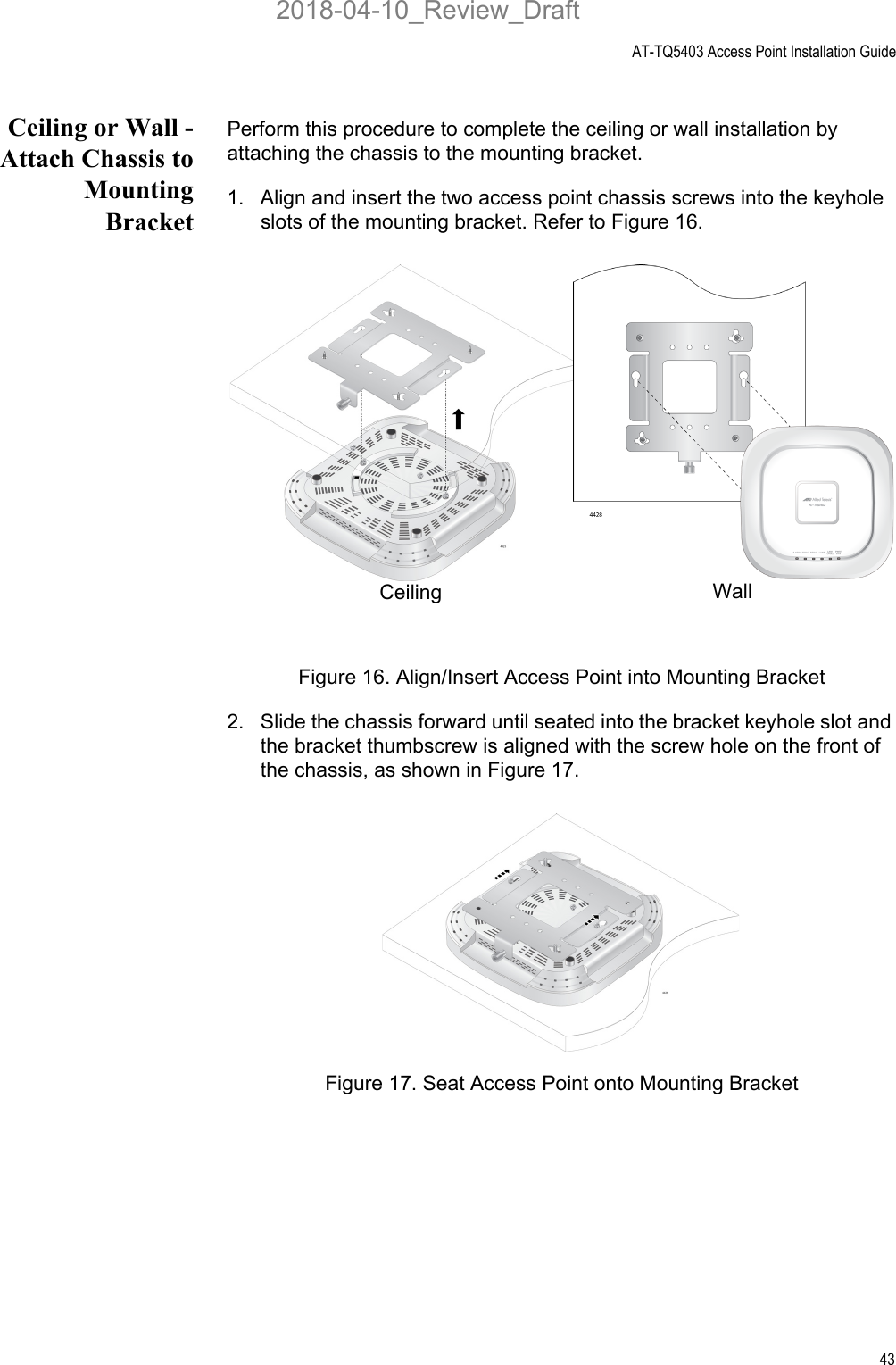
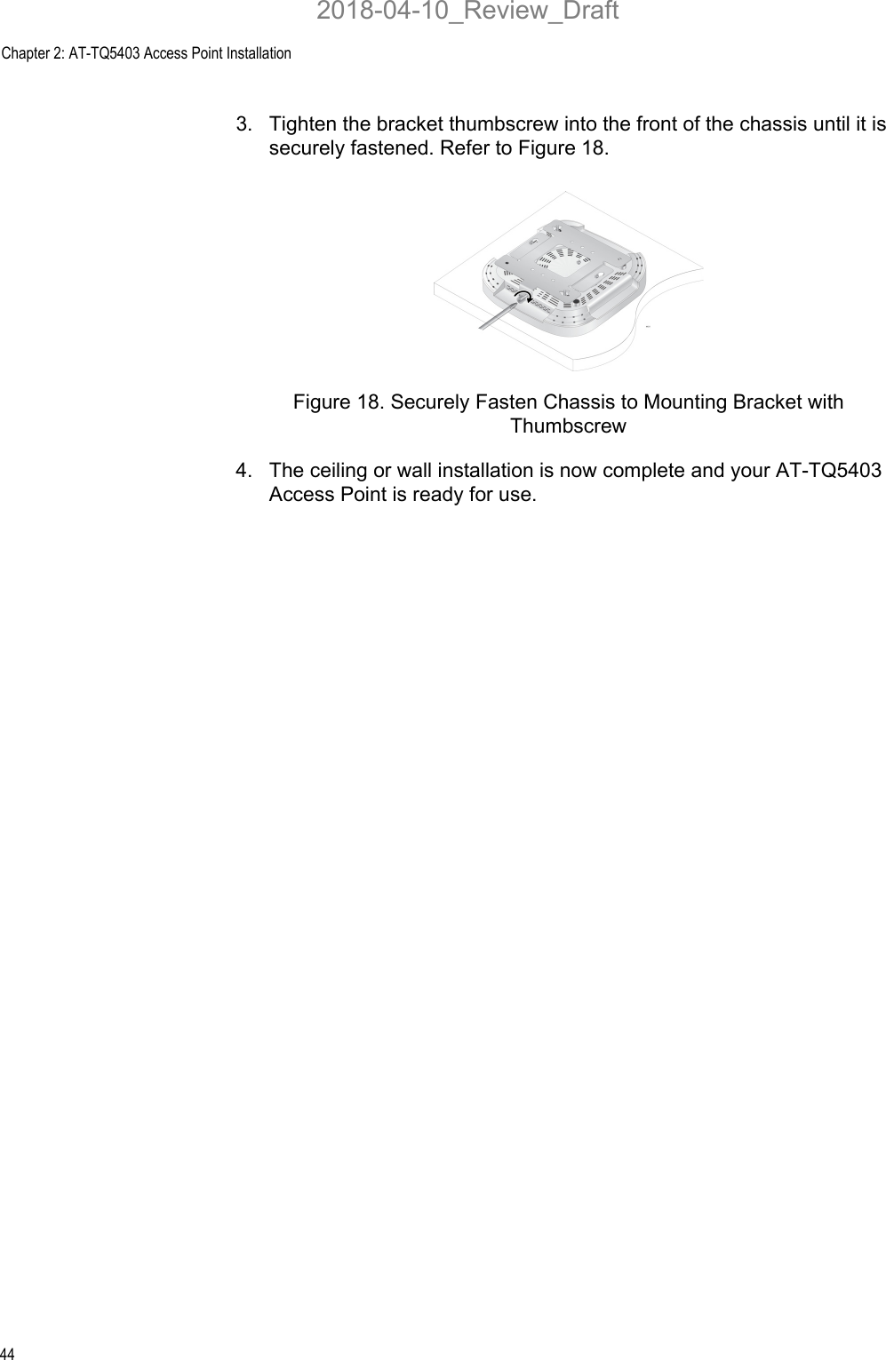
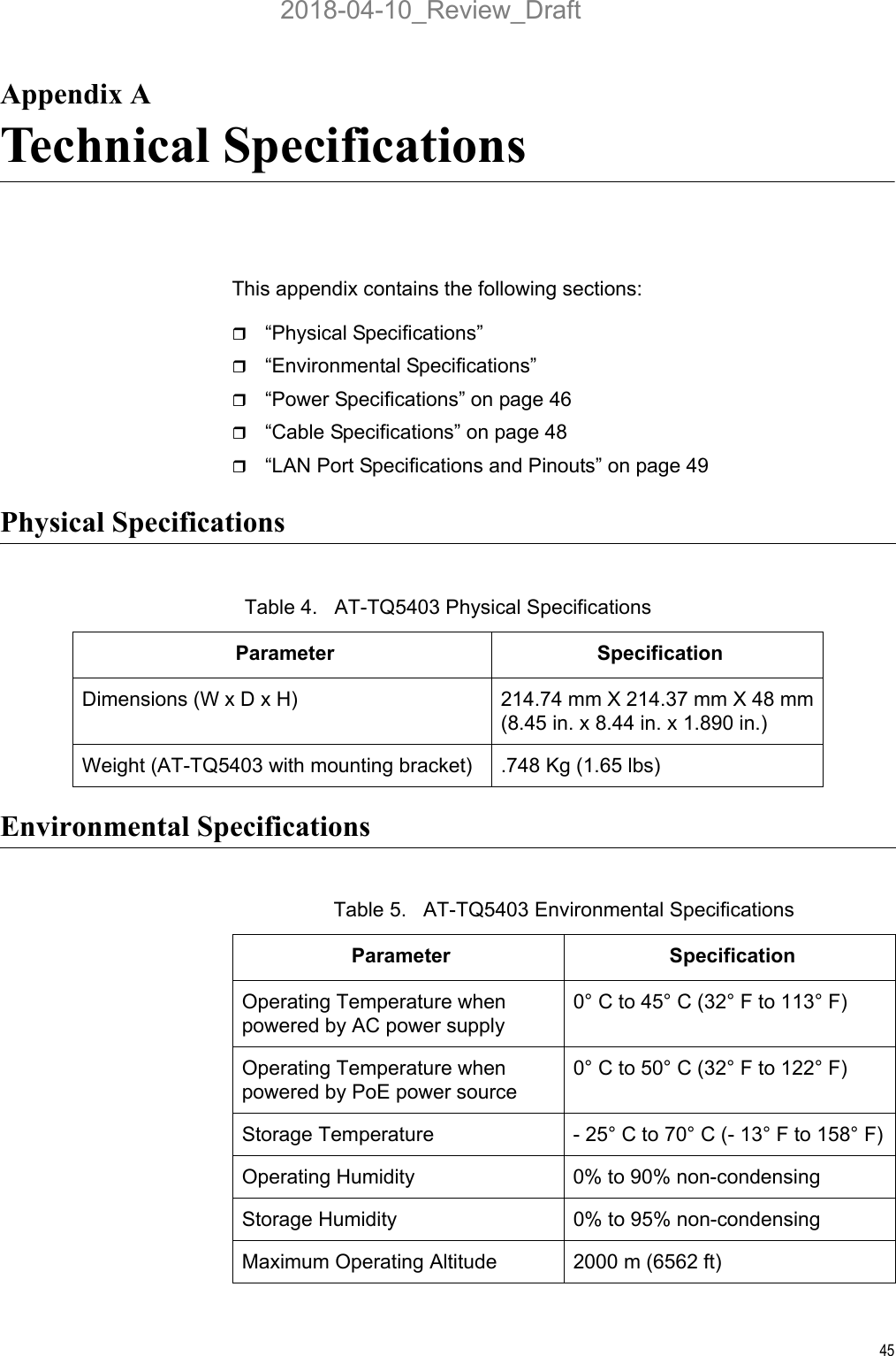
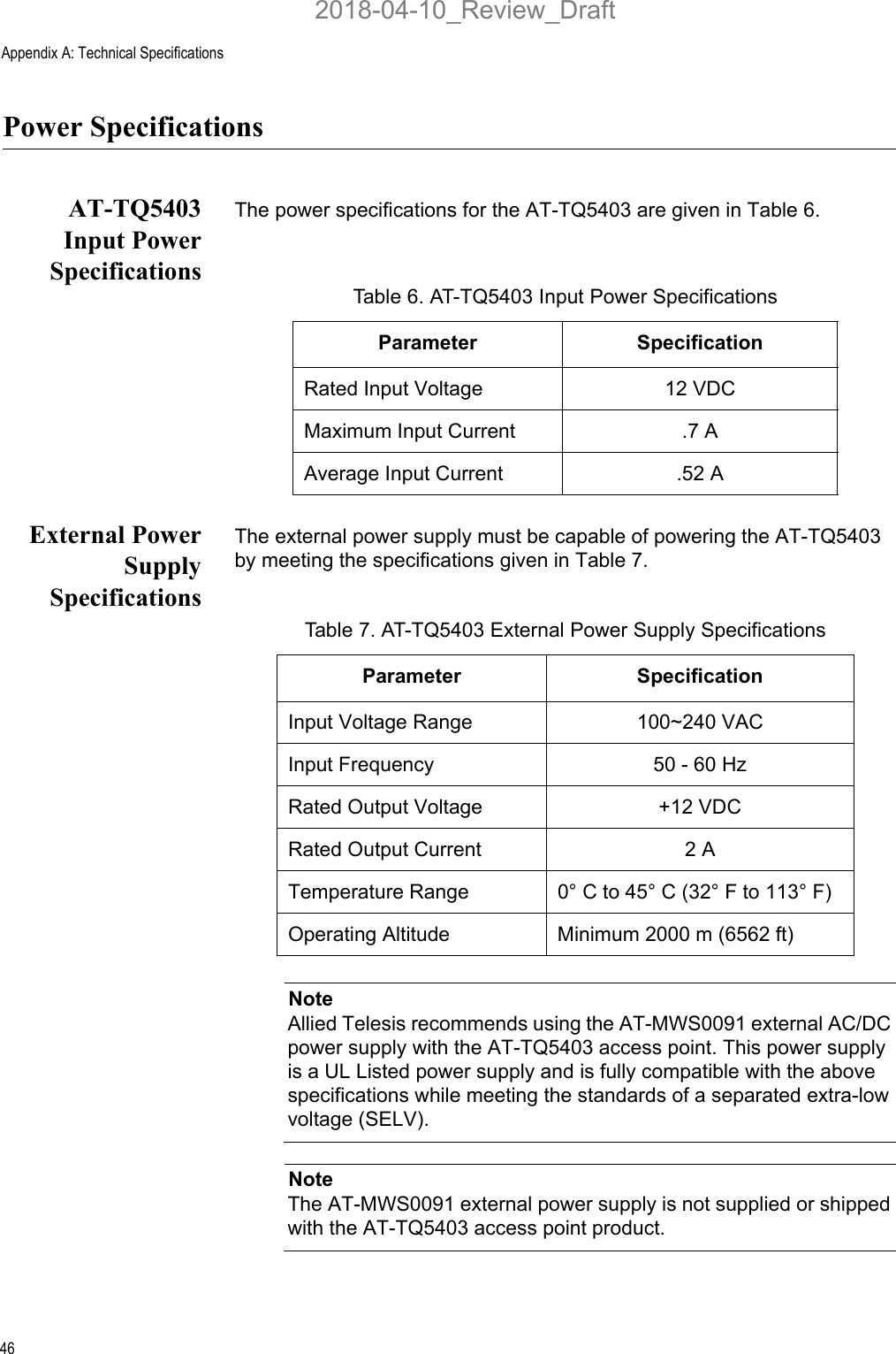
![Appendix B: Regulatory Statements54Europe - EU Declaration of ConformityHereby, Allied Telesis, Inc. declares that the radio equipment type [AT-TQ5403] is in compliance with Directive 2014/53/EU.OperatingFrequencies andMaximumTransmissionPower LevelsThe operating frequencies and maximum transmission power levels for wireless devices operated in the EU are listed below:- 2412-2472 MHz: 19.23 dBm (Beamforming), 18.79dBm (Non-Beamforming)- 5150-5250 MHz: 22.11 dBm (Beamforming), 22.13dBm (Non-Beamforming)- 5250-5350 MHz: 22.06 dBm (Beamforming), 21.87dBm (Non-Beamforming)- 5470-5725 MHz: 28.97 dBm (Beamforming), 28.70dBm (Non-Beamforming)NoteOperations in the 5.15 - 5.35 GHz band are restricted to indoor usage only.RadiationExposureStatementThis equipment complies with EU radiation exposure limits set forth for an uncontrolled environment. This equipment should be installed and operated with a minimum distance of 20 cm between the radiator and your body.Importer Allied Telesis International BVIncheonweg 7, 1437 EK RozenburgNoteContact Allied Telesis for the EU conformity statement. To contact Allied Telesis, visit our web site at www.alliedtelesis.com/contact.2018-04-10_Review_Draft](https://usermanual.wiki/Allied-Telesis-K-K/TQ5403.Users-Manual/User-Guide-3818270-Page-54.png)