Allied Telesis K K TQ5403E 802.11ac wave2 2x2 tri-radio 2.4G/5G/5G wireless AP User Manual
Allied Telesis K.K. 802.11ac wave2 2x2 tri-radio 2.4G/5G/5G wireless AP
User Manual
613-002655 Rev. A
AT-TQ5403e
Enterprise-Class Outdoor Wireless Access Point
with IEEE802.11a/b/g/n/ac Tri-Radio
Installation Guide
Draft 5 on February 14, 2019
Copyright 2019 Allied Telesis, Inc.
All rights reserved. No part of this publication may be reproduced without prior written permission from Allied Telesis, Inc.
Allied Telesis and the Allied Telesis logo are trademarks of Allied Telesis, Incorporated. All other product names, company names,
logos or other designations mentioned herein are trademarks or registered trademarks of their respective owners.
Allied Telesis, Inc. reserves the right to make changes in specifications and other information contained in this document without prior
written notice. The information provided herein is subject to change without notice. In no event shall Allied Telesis, Inc. be liable for
any incidental, special, indirect, or consequential damages whatsoever, including but not limited to lost profits, arising out of or related
to this manual or the information contained herein, even if Allied Telesis, Inc. has been advised of, known, or should have known, the
possibility of such damages.
Draft 5 on February 14, 2019

3
Electrical Safety and Emissions
Standards
This product meets the following standards:
Federal Communications Commission Interference Statement
Declaration of Conformity
Manufacturer Name: Allied Telesis, Inc.
Declares that the product: Enterprise-class Outdoor Wireless Access Point
Model Number: AT-TQ5403e
This device complies with Part 15 of the FCC Rules. Operation is subject to the following two
conditions: (1) This device may not cause harmful interference, and (2) this device must accept
any interference received, including interference that may cause undesired operation.
This equipment has been tested and found to comply with the limits for a Class B digital device,
pursuant to Part 15 of the FCC Rules. These limits are designed to provide reasonable protection
against harmful interference in a residential installation. This equipment generates, uses and can
radiate radio frequency energy and, if not installed and used in accordance with the instructions,
may cause harmful interference to radio communications. However, there is no guarantee that
interference will not occur in a particular installation. If this equipment does cause harmful
interference to radio or television reception, which can be determined by turning the equipment
off and on, the user is encouraged to try to correct the interference by one of the following
measures:
Reorient or relocate the receiving antenna.
Increase the separation between the equipment and receiver.
Connect the equipment into an outlet on a circuit different from that to which the receiver is
connected.
Consult the dealer or an experienced radio/TV technician for help.
Caution
FCC Caution: Any changes or modifications not expressly approved by the party responsible
for compliance could void the user's authority to operate this equipment. E80
This transmitter must not be co-located or operating in conjunction with any other antenna or
transmitter.
The band from 5600-5650MHz will be disabled by the software during the manufacturing and
cannot be changed by the end user. This device meets all the other requirements specified in
Part 15E, Section 15.407 of the FCC Rules.
Draft 5 on February 14, 2019

4
Radiation Exposure Statement:
This equipment complies with FCC radiation exposure limits set forth for an uncontrolled
environment. This equipment should be installed and operated with minimum distance 20cm
between the radiator & your body.
European Union Restriction of the Use of Certain Hazardous
Substances (RoHS) in Electrical and Electronic Equipment
This Allied Telesis RoHS-compliant product conforms to the European Union Restriction of the
Use of Certain Hazardous Substances (RoHS) in Electrical and Electronic Equipment. Allied
Telesis ensures RoHS conformance by requiring supplier Declarations of Conformity, monitoring
incoming materials, and maintaining manufacturing process controls.
Safety and Electromagnetic Emissions Certificates
Standard Compliance
RoHs compliant
European Union RoHS (Directive 2011/65/EU of the European Parliament and of the Council
of 8 June 2011 on the restriction of the use of certain hazardous substances in electrical and
electronic equipment.)
Certificates
CE
FCC
RCM
Wi-Fi CERTIFIED
Electromagnetic Compatibility (EMC)
EN 301 489-1
EN 301 489-17
EN 55032
EN 55024
EN 55035
EN 61000-4-2
EN 61000-4-3
EN 61000-4-4
EN 61000-4-5
Draft 5 on February 14, 2019

5
EN 61000-4-6
EN 61000-4-8
AS/NZS CISPR 32
FCC 47 CFR Part 15, Subpart B
ICES-003
Radio Equipment
EN 300 328
EN 301 893
AS/NZS 4268
FCC 47 CFR Part 15, Subpart C
FCC 47 CFR Part 15, Subpart E
RSS-247
RSS-Gen
RSS-102
FCC: OET Bulletin No. 65 Supplement C
EN 50385
Safety
EN 60950-1
IEC 60950-1
TUV-T
UL 60950-1
UL 60950-22
CAN/CSA C22.2 No. 60950-1-07
CAN/CSA-C22.2 No. 60950-22-07
IEC 60950-22
IEC 60529
EN 62368-1
UL 62368-1
IEC 62368-1
Translated Safety Statements
Important: The indicates that a translation of the safety statement is available in a PDF document
titled Translated Safety Statements on the Allied Telesis website at
www.alliedtelesis.com/support.
Draft 5 on February 14, 2019

7
Contents
Preface ..............................................................................................................................................................9
Safety Symbols Used in this Document..................................................................................................... 10
Professional Installation Instructions.......................................................................................................... 11
Contacting Allied Telesis............................................................................................................................ 12
Chapter 1: Product Description ...................................................................................................................13
Overview .................................................................................................................................................... 14
Features..................................................................................................................................................... 16
LEDs .......................................................................................................................................................... 17
LAN Port..................................................................................................................................................... 18
Power over Ethernet (PoE).................................................................................................................. 18
Connector Type ................................................................................................................................... 18
Speed .................................................................................................................................................. 18
Duplex Mode ....................................................................................................................................... 18
Automatic MDIX Detection .................................................................................................................. 19
Port Pinouts ......................................................................................................................................... 19
Reset Button .............................................................................................................................................. 20
Cable Specifications................................................................................................................................... 21
Cable Requirements............................................................................................................................ 21
Maximum Distance .............................................................................................................................. 21
Chapter 2: Installing the Access Point ........................................................................................................23
Reviewing Safety Precautions ................................................................................................................... 24
Unpacking the Access Point ...................................................................................................................... 27
Attaching the Ground Cable to the Access Point ....................................................................................... 30
Guidelines............................................................................................................................................ 30
What to Prepare for Attaching the Ground Cable................................................................................ 30
Attaching the Ground Cable to the Access Point ................................................................................ 31
Connecting the Access Point with the Ethernet Cable............................................................................... 32
Attaching the Antennas to the Access Point .............................................................................................. 34
Installing the Access Point on a Wall ......................................................................................................... 36
Guidelines............................................................................................................................................ 36
What to Prepare for Wall Installation ................................................................................................... 37
Installing the Access Point on a Wall................................................................................................... 37
Installing the Access Point on a Pole ......................................................................................................... 40
Guidelines for Pole Installation ............................................................................................................ 40
What to Prepare for Pole Installation ................................................................................................... 40
Installing the Access Point on a Pole .................................................................................................. 41
Adjusting the Position Upward or Downward ...................................................................................... 42
Starting the Initial Management Session on the Access Point................................................................... 43
Setting the Country Setting ........................................................................................................................ 45
Appendix A: Technical Specifications and Statements .............................................................................47
Physical Specifications............................................................................................................................... 47
Power Specifications.................................................................................................................................. 47
Environmental Specifications ..................................................................................................................... 48
Draft 5 on February 14, 2019
Contents
8
Antenna Specifications ............................................................................................................................... 48
LAN Port .....................................................................................................................................................49
Safety and Electromagnetic Emissions Certifications ................................................................................ 51
Operation Frequency Information...............................................................................................................52
IC Statements............................................................................................................................................. 53
IC Radiation Exposure Statement........................................................................................................53
Déclaration d’exposition à la radiation .................................................................................................53
Caution................................................................................................................................................. 53
Avertissement ...................................................................................................................................... 54
Professional Installation Instruction...................................................................................................... 54
Instructions d'installation professionnelle:............................................................................................54
Europe - EU Declaration of Conformity ...................................................................................................... 55
Operating Frequencies and Maximum Transmission Power Levels .................................................... 55
Draft 5 on February 14, 2019

9
Preface
This guide contains the hardware installation instructions for the
AT-TQ5403e Enterprise-Class Outdoor Wireless Access Point. This
preface contains the following sections:
“Safety Symbols Used in this Document” on page 10
“Professional Installation Instructions” on page 11
“Contacting Allied Telesis” on page 12
Draft 5 on February 14, 2019
AT-TQ5403e Outdoor Wireless Access Point Installation Guide
10
Safety Symbols Used in this Document
This document uses the following conventions.
Note
Notes provide additional information.
Caution
Cautions inform you that performing or omitting a specific action
may result in equipment damage or loss of data.
Attention
Les mises en garde vous informent que l'exécution ou l'omission
d'une action spécifique peut endommager l'équipement ou entraîner
une perte de données.
Warning
Warnings inform you that performing or omitting a specific action
may result in bodily injury.
Advertissement
Les avertissements vous informent que l'exécution ou l'omission
d'une action spécifique peut entraîner des blessures corporelles.
Draft 5 on February 14, 2019

Preface
11
Professional Installation Instructions
You must comply with the following cautions:
Installation personal
This product is designed for specific application and needs to be
installed by a qualified personal who has RF and related rule
knowledge. The general user shall not attempt to install or change the
setting.
Installation location
The product shall be installed at a location where the radiating antenna
can be kept 20cm from nearby person in normal operation condition to
meet regulatory RF exposure requirement.
Draft 5 on February 14, 2019

AT-TQ5403e Outdoor Wireless Access Point Installation Guide
12
Contacting Allied Telesis
If you need assistance with this product, you may contact Allied Telesis
technical support by going to the Support & Services section of the Allied
Telesis web site at www.alliedtelesis.com/support. You can find links
for the following services on this page:
24/7 Online Support — Enter our interactive support center to
search for answers to your product questions in our knowledge
database, check support tickets, learn about Return Merchandise
Authorizations (RMAs), and contact Allied Telesis technical
experts.
USA and EMEA phone support — Select the phone number that
best fits your location and customer type.
Hardware warranty information — Learn about Allied Telesis
warranties and register your product online.
Replacement Services — Submit an RMA request via our
interactive support center.
Documentation — View the most recent installation and user
guides, software release notes, white papers, and data sheets for
your products.
Software Downloads — Download the latest software releases for
your managed products.
For sales or corporate information, go to www.alliedtelesis.com/
purchase.
Draft 5 on February 14, 2019

13
Chapter 1
Product Description
This chapter describes the hardware components of the AT-TQ5403e
access point. This chapter contains the following sections:
“Overview” on page 14
“Features” on page 16
“LEDs” on page 17
“LAN Port” on page 18
“Reset Button” on page 20
“Cable Specifications” on page 21
Draft 5 on February 14, 2019

AT-TQ5403e Outdoor Wireless Access Point Installation Guide
14
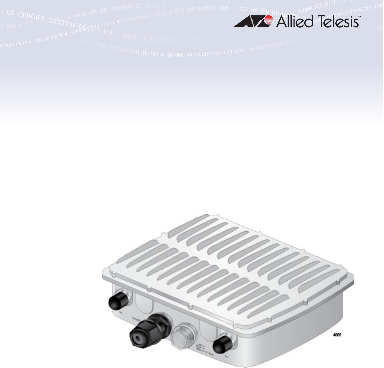
Overview
The AT-TQ5403e access point is an enterprise-class outdoor wireless
access point designed to expand wireless networks to outdoor venues,
such as ski and beach resorts, sports arenas, or college and corporate
campuses.
The access point comes with one PoE+ capable LAN port to connect to
the network as well as the power supply.
This device can be mounted on a wall or pole.
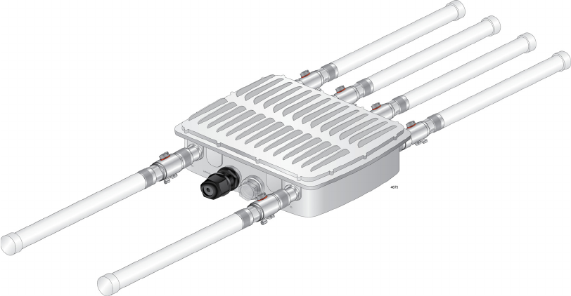
The AT-TQ5403e access point is illustrated in Figure 1.
Figure 1. AT-TQ5403e Access Point
The front panel components of the AT-TQ5403e access point are
illustrated in Figure 2.
Figure 2. AT-TQ5403e Access Point Antenna Front Panel
LAN Port
5GHz Antenna
Connector
5GHz Antenna
Connector
LEDs and Reset Button
Draft 5 on February 14, 2019
Chapter 1: Product Description
15
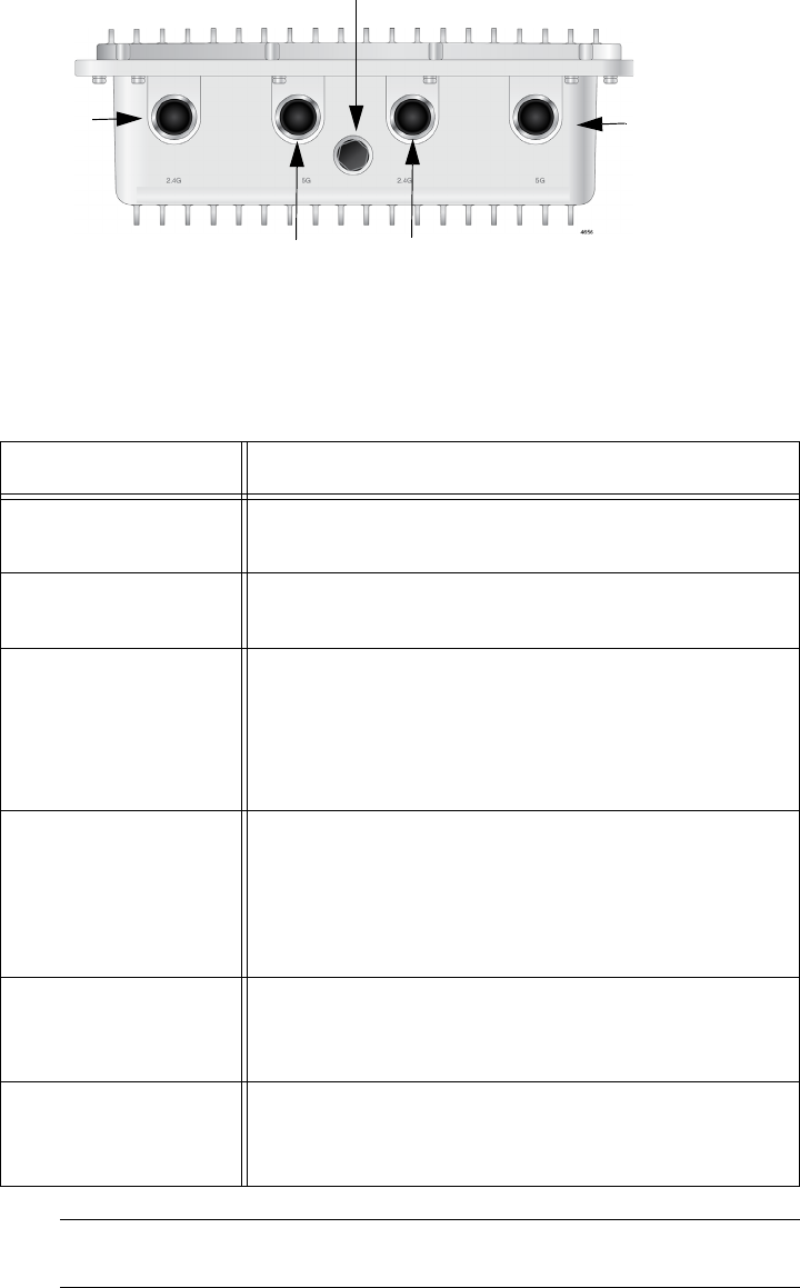
The back panel components of the AT-TQ5403e access point are
illustrated in Figure 3.
Figure 3. AT-TQ5403e Access Point Antenna Back Panel
The components are listed in Table 1.
Note
Do not remove the Gore® vent plug from the access point.
5GHz Antenna Connector 2.4GHz Antenna Connector
Gore
®
vent
2.4GHz Antenna
Connector
5GHz Antenna
Connector
Table 1. Components of the Access Point
Component Description
5 GHz Antenna
Connector
N-type female connector for the 5 GHz antenna
2.4 GHz Antenna
Connector
N-type female connector for the 2.4 GHz antenna
LAN Port (PoE Input) The LAN port connects the access point to your
local area network. It supports PoE+. This PoE+
capable LAN port is the only way to supply power
to this access point. You must connect this LAN
port to a PoE-capable switch.
LEDs Indicates the following status:
LAN
WLAN
Power
Reset Button The reset button reboots the system. Remove the
clear dust cover and press the button using your
finger.
Gore® vent The vent equalizes housing pressures, protects
against dirt, dust, humidity and water, and reduces
condensation.
Draft 5 on February 14, 2019

AT-TQ5403e Outdoor Wireless Access Point Installation Guide
16
Features
The main features of the product are listed here:
Tri-radio: 2.4 GHz x 1 and 5 GHz x 2
IEEE 802.11a/b/g/n/ac
2x2:2ss MIMO
Maximum capacity 2.4 GHz: 300 Mbps
Maximum capacity 5 GHz: 867 Mbps
Wireless Distribution System (WDS) bridges
Neighbor AP detection
Multiple SSIDs
One 10/100/1000Base-T Ethernet port with Auto-Negotiation, auto
MDI/MDIX, and IEEE 802.3at Power over Ethernet (PoE+)
IEEE 802.3 (10Base-T), IEEE 802.3u (100Base-TX), and IEEE
802.3ab (1000Base-T) compliance on the Ethernet port
MAC address filtering for wireless access security
Broadcast and multicast rate limiting
DHCP client
RADIUS accounting with external RADIUS server
Network Time Protocol (NTP) client
Domain name server (DNS) client
IEEE 802.1x authentication
WPA-Personal and WPA-Enterprise with WPA, WPA2, TKIP, and
CCMP (AES) authentication and encryption
Static WEP encryption
HTTP and HTTPS web browser management
SNMPv1 and v2c management
Quality of Service
Event log
Syslog client
Outdoor installation on a wall or pole
External antenna surge protector
N-type female antenna connectors for replacing antennas
Aluminum chassis to repel ultraviolet (UV) radiation and withstand
high temperature
Draft 5 on February 14, 2019

Chapter 1: Product Description
17
LEDs
The LEDs on the AT-TQ5403e access point are described in Table 2.
Table 2. LEDs
LED State Description
LAN Solid Green A link is established and the port is operating
normally.
Blinking
Green
Data is being transmitted/received.
Off A link is not established.
WLAN Solid Green One or more radio among Radio1, Radio2,
and Radio3 is enabled.
Off Radio1, Radio2, and Radio3 are all disabled.
Power Solid Green The unit is receiving power that is within the
normal operating range.
Blinking
Green
The access point is booting up or upgrading
the firmware.
Off The power supply is not receiving power
through the LAN port.
Draft 5 on February 14, 2019

AT-TQ5403e Outdoor Wireless Access Point Installation Guide
18
LAN Port
The AT-TQ5403e access point has one LAN port to connect to your Local
Area Network (LAN), typically through an Ethernet switch.
Power over
Ethernet (PoE)
The AT-TQ5403e access point supports Power over Ethernet Plus (PoE+)
on the LAN port. The access point is a PoE+ class 4 powered device with
a maximum power consumption of 25.5 watts. When the port is connected
to a PoE+ Ethernet switch, the access point receives its power over the
network cable that carries the network traffic. The LAN port is the only way
to supply the power to the device.
Note
The PoE device that supplies power to this device, such as a switch,
must be a UL listed Information Technology Equipment (ITE).
Connector Type The LAN port has an eight-pin RJ45 connector. The port uses four pins at
10 or 100 Mbps and all eight pins at 1000 Mbps. The pin assignments are
listed in “LAN Port” on page 49.
Speed The LAN port can operate at 10, 100, or 1000 Mbps. The speed is set
automatically with Auto-Negotiation. You cannot disable Auto-Negotiation
on the port.
Note
The LAN port should be connected to a network device that also
adjusts its speed with Auto-Negotiation. If the network device does
not support Auto-Negotiation, the LAN port operates at 10 Mbps,
which may reduce network performance.
Duplex Mode The LAN port can operate in either half- or full-duplex mode at 10 or 100
Mbps, and full-duplex mode at 1000 Mbps. The port is IEEE 802.3u-
compliant and uses Auto-Negotiation to set the duplex mode. You cannot
disable Auto-Negotiation on the port.
Note
The LAN port should be connected to a network device that also
sets its duplex mode with Auto-Negotiation. If the network device
does not support Auto-Negotiation, the LAN port operates at half-
duplex mode. This may result in a duplex mode mismatch if the
network device is operating at full duplex.
Draft 5 on February 14, 2019
Chapter 1: Product Description
19
Automatic MDIX
Detection
The 10/100/1000 Mbps twisted-pair port is IEEE 802.3ab compliant and
features automatic MDIX detection when operating at 10 or 100 Mbps.
(Automatic MDIX detection does not apply to 1000 Mbps.) This feature
automatically configures the port to MDI or MDI-X depending on the wiring
configuration of the port on the Ethernet switch.
You may not disable automatic MDIX detection. For automatic MDIX
detection to work properly, it must also be present on the Ethernet switch.
The LAN port defaults to MDIX if it is connected to a network device that
does not support automatic MDIX detection.
Port Pinouts Refer to Table 11 on page 49 for the port pinouts of the LAN port when it is
operating at 10 or 100 Mbps in the MDI configuration and Table 12 on
page 50 for the MDI-X configuration. Refer to Table 13 on page 50 for the
port pinouts when the port is operating at 1000 Mbps.
Draft 5 on February 14, 2019

AT-TQ5403e Outdoor Wireless Access Point Installation Guide
20
Reset Button
The reset button on the front panel is used to return the parameter settings
of the device to its default values. You might use the button if you want to
discard the current configuration of the device or because you forgot the
password to the manager account and cannot manage the device.
To reset the device, remove the clear cap on the front panel and press the
black button for five seconds and release. The reset button is protected to
prevent from being accidentally pressed.
By default, the reset button is disabled. To enable reset button, see a User
Guide for this access point.
Draft 5 on February 14, 2019

Chapter 1: Product Description
21
Cable Specifications
To connect the AT-TQ5403e Access Point to your LAN, you must provide
cables. Here are cable requirements and options.
Cable
Requirements
The cable requirements for the LAN port are listed in Table 3.
Maximum
Distance
The LAN port has a maximum operating distance of 100 meters (328 feet).
Table 3. Twisted Pair Cable for the LAN Port
Cable Type
10Mbps 100Mbps 1000Mbps
PoE+ PoE+ PoE+
Standard TIA/EIA 568-A-compliant
Category 5 shielded or unshielded
cabling with 100 ohm impedance and
100 MHz frequency.
Yes Yes No
Standard TIA/EIA 568-B-compliant
Enhanced Category 5 (Cat 5e)
shielded or unshielded cabling with
100 ohm impedance and 100 MHz
frequency.
Yes Yes Yes
Standard TIA/EIA 568-B-compliant
Category 6 or 6a shielded cabling.
Yes Yes Yes
Draft 5 on February 14, 2019

23
Chapter 2
Installing the Access Point
This chapter describes how to install the AT-TQ5403e access point. This
chapter contains the following sections:
“Reviewing Safety Precautions” on page 24
“Unpacking the Access Point” on page 27
“Attaching the Ground Cable to the Access Point” on page 30
“Connecting the Access Point with the Ethernet Cable” on page 32
“Attaching the Antennas to the Access Point” on page 34
“Installing the Access Point on a Wall” on page 36
“Installing the Access Point on a Pole” on page 40
“Starting the Initial Management Session on the Access Point” on
page 43
“Setting the Country Setting” on page 45
Note
The non-US model of this product has a country code setting that
must be set during the initial management session of the unit. The
setting ensures that the unit operates in compliance with the laws
and regulations of your country or region.
For the US model, the country code is preset and cannot be
changed. Per FCC regulations, the country code setting for all WiFi
products marketed in the US must be fixed to US operational
channels only.
Draft 5 on February 14, 2019
AT-TQ5403e Outdoor Wireless Access Point Installation Guide
24
Reviewing Safety Precautions
Please review the following safety precautions before you begin to install
the access point.
Note
The indicates that a translation of the safety statement is
available in a PDF document titled Translated Safety Statements on
the Allied Telesis website at www.alliedtelesis.com/support.
Warning
To prevent electric shock, do not remove the cover. No user-
serviceable parts inside. This unit contains hazardous voltages and
should only be opened by a trained and qualified technician. To
avoid the possibility of electric shock, disconnect electric power to
the product before connecting or disconnecting the LAN cables.
E1
Advertissement
Pour éviter tout risque d’électroc ution, ne pas enlever le capot.
L’appareil ne contient aucun composant réparable par l’utilisateur. Il
est exposé à des tensions dangereuses et ne doit être ouvert que
par un technicien compétent et qualifié. Pour éviter tout risque
d’électrocution, débrancher l’alim entation électrique du produit
avant de connecter ou de déconnecter les câbles de réseau local.
E1
Warning
Do not work on equipment or cables during periods of lightning
activity. E2
Advertissement
Ne pas travailler sur cet équipeme nt ni sur ses câbles en présence
de foudre. E2
Warning
Operating Temperature. This product is designed for a maximum
ambient temperature of 65°C E50
Draft 5 on February 14, 2019
Chapter 2: Installing the Access Point
25
Advertissement
Température de fonctionnement. Ce produit est conçu pour une
température ambiante maximale de 65 °C. E50
Caution
FCC Caution: Any changes or modifications not expressly approved
by the party responsible for compliance could void the user's
authority to operate this equipment. E80
Attention
Avertissement de la FCC: tout changement ou modification non
expressément approuvé par la partie responsable de la conformité
pourrait annuler l'autorité de l'utilisateur à utiliser cet appareil.
E80
Note
All Countries: Install product in accordance with local and National
Electrical Codes. E8
Note
You should verify that your PoE network adheres to the standards of
a separated extra-low voltage (SELV) circuit before using the PoE
feature on the wireless access point.
Warning
Only trained and qualified personnel are allowed to install or to
replace this equipment. E14
Advertissement
Seul le personnel qualifié et compétent est autorisé à installer ou à
remplacer cet équipement. E14
Warning
This equipment shall be installed in a Restricted Access location.
E45
Draft 5 on February 14, 2019
AT-TQ5403e Outdoor Wireless Access Point Installation Guide
26
Advertissement
Cet équipement doit être installé dans un endroit à accès restreint.
E45
Warning
Hot Surface, Do Not Touch! - The finned surface on the back of
the chassis is a heat sink and can become dangerously hot when
the unit is operating. E114
Advertissement
Surface chaude, ne pas toucher! - La surface à ailettes à l'arrière
du châssis est un dissipateur de chaleur et peut devenir
dangereusement chaude lorsque l'unité est en marche. E114
Draft 5 on February 14, 2019
Chapter 2: Installing the Access Point
27
Unpacking the Access Point
To unpack the access point, perform the following procedure:
1. Remove all components from the shipping boxes.
Note
Store the packaging material in a safe location. You must use the
original shipping material if you need to return the unit to Allied
Telesis.
2. Verify that all components listed in Table 4 are included in your
shipping boxes.
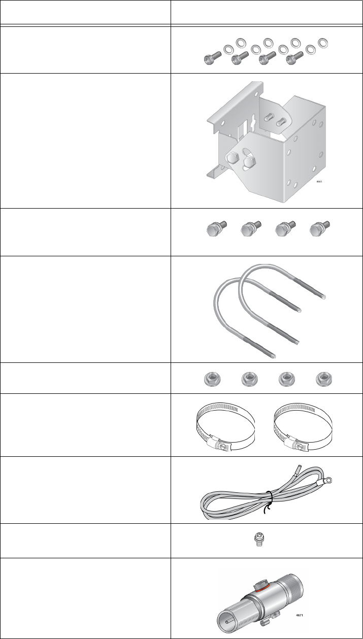
Table 4. Components in the Shipping Boxes
Name Component
4 x 5GHz Antenna
2 x 2.4GHz Antenna
Mounting Base
Draft 5 on February 14, 2019
AT-TQ5403e Outdoor Wireless Access Point Installation Guide
28
4 Sets of a Screw, Washer, and
Spring Washer to attach the
mount base to the access point
Pole-mount Bracket
4 Sets of a Hex-head bolt,
Washer, Spring Washer for the
Pole-mount Brackets
2 x U-Bold
4 x Nut for U-Bold
2 x Pole Strap
Ground cable
1 Set of Screw, Washer, Spring
Washer for the Ground Cable
6 x external surge protector
Table 4. Components in the Shipping Boxes (Continued)
Name Component
Draft 5 on February 14, 2019
Chapter 2: Installing the Access Point
29
3. If any item is missing or damaged, contact your Allied Telesis sales
representative for assistance.
Draft 5 on February 14, 2019

AT-TQ5403e Outdoor Wireless Access Point Installation Guide
30
Attaching the Ground Cable to the Access Point
To protect the device from lightning strikes and against electrostatic
discharge (ESD), attach the ground cable to the access point.
Guidelines Review the following guidelines before attaching the ground cable to the
access point:
Before installing the mounting base to the access point, attach the
ground cable to the access point.
Connect the ground cable straight to the earth ground; cut off the
extra length of the ground cable.
Prevent the ground cable from being sharply bent, looped, or
coiled.
Connect the surge protector ground cable and the equipment
ground to a single common ground. The equipment ground
includes power ground and telecommunications ground.
The recommended earth ground impedance is less than 1.0 ohm.
Measure the ground impedance at the point where the surge
protector ground cable, not at the ground rod.
If you provide your own ground cable, use a 10 AWG or larger
stranded wire as a ground cable.
What to Prepare
for Attaching the
Ground Cable
You need the following items to attach the ground cable to the access
point:
AT-TQ5403e Access Point
Ground cable
One screw for the ground cable
Phillips-head screwdriver
Note
A Phillip-head screwdriver is not included in the shipping box.
Draft 5 on February 14, 2019
Chapter 2: Installing the Access Point
31
Attaching the
Ground Cable to
the Access Point
To attach the ground cable to the access point, perform the following
procedure:
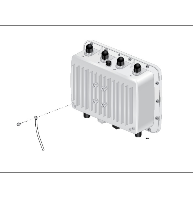
1. Align the ground cable hole on the access point with the ring terminal
of the ground cable. See Figure 4.
Note
You can select one of two ground cable holes located at the bottom
corners on the back of the access point.
Figure 4. Aligning the Access Point with Ground Cable
Note
The ground wire should be 20AWG or larger and the screw should
be 3.5mm or larger.
2. Drive the screw through the holes to attach the ground cable to the
access point.
3. Cut off the extra length of the ground cable to make it connected
straight to the ground point.
4. Attach the other terminal of the ground cable to a circuit breaker,
ground rod, or earth ground.
Draft 5 on February 14, 2019
AT-TQ5403e Outdoor Wireless Access Point Installation Guide
32
Connecting the Access Point with the Ethernet Cable
To connect the access point with the Ethernet cable, perform the following
procedure:
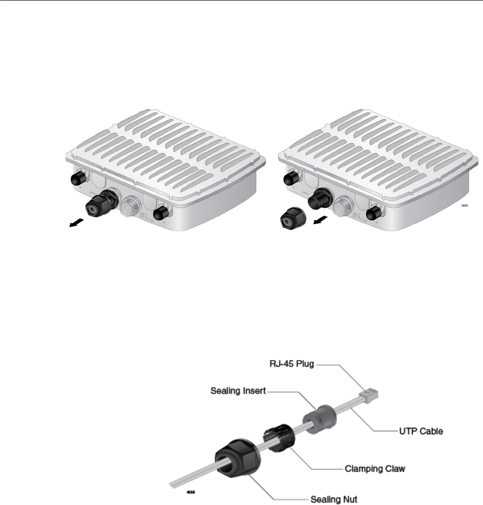
1. Unscrew the cap at the LAN port to remove the cap from the access
point. See Figure 5.
Figure 5. Removing the Cap from the LAN Port
2. Store the cap in a secured place.
3. Take the sealing nut apart.
4. Pass the LAN cable through the sealing nut, and attach the sealing
insert and clamping claw to the cable. See Figure 6.
Figure 6. Applying the Sealing Parts to the LAN Cable
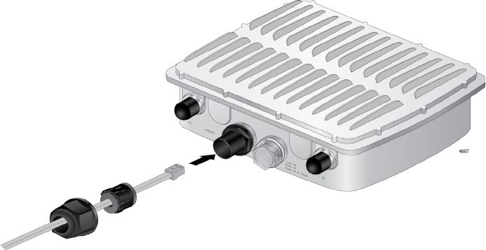
5. Connect the RJ-45 plug into the LAN port and screw the sealing nut to
the access point. See Figure 7 on page 33.
Draft 5 on February 14, 2019
Chapter 2: Installing the Access Point
33
Figure 7. Connecting the LAN Cable and Attaching the Sealing Nut
6. Connect the other RJ-45 plug to the PoE switch.
Draft 5 on February 14, 2019
AT-TQ5403e Outdoor Wireless Access Point Installation Guide
34
Attaching the Antennas to the Access Point
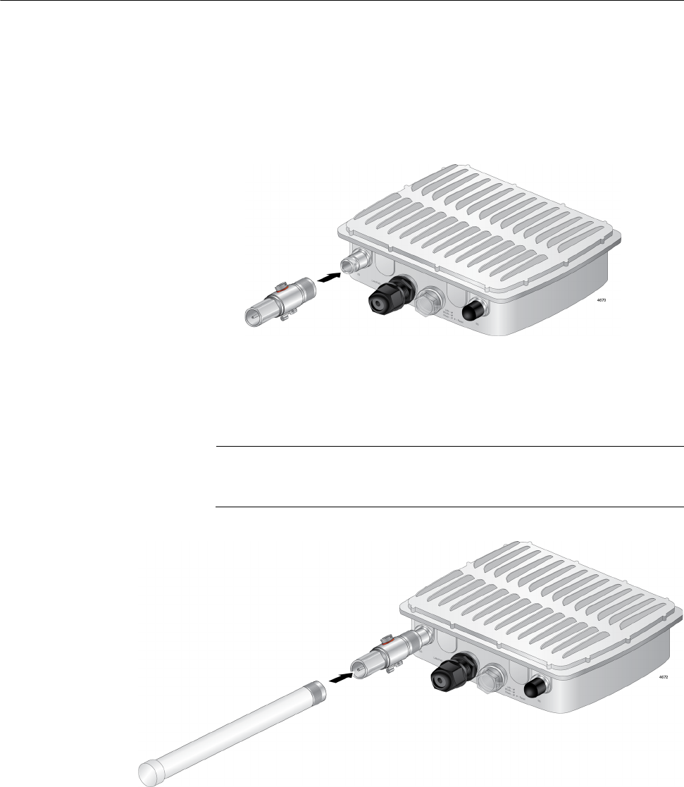
To install the antennas, perform the following procedure:
1. Remove the blind caps covering the antenna connectors from the
main unit.
2. Attach a surge protector to an antenna connector. See Figure 8.
Figure 8. Attaching a Surge Protector to an Antenna Connector
3. Screw an antenna into the surge protector that you just attached to the
access point. See Figure 9.
Note
You must install 5GHz antennas to 5GHz antenna connectors and
2.4GHz antennas to 2.4GHz antenna connectors.
Figure 9. Installing an Antennas to the Surge Protector
Draft 5 on February 14, 2019
AT-TQ5403e Outdoor Wireless Access Point Installation Guide
36
Installing the Access Point on a Wall
The AT-TQ5403e access point can be mounted on a wall.
To install the access point, perform the following procedures:
Guidelines Review the following guidelines before installing the access point on a
wall:
Attach the ground cable before attaching the mounting base to the
access point.
Connect the Ethernet cable to the access point before installing the
access point on a wall or pole because connecting the Ethernet
cable is difficult after the access point is installed.
Attach the antennas to the access point before installing it on a
wall or pole because attaching the antennas is difficult after the
access point is installed.
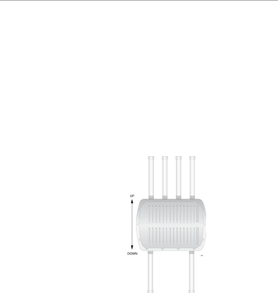
The access point must be installed the front panel down as shown
in Figure 12.
Figure 11. Orientation of the Access Point
The mounting base can be in a vertical or horizontal position. See
Figure 12 on page 37.
Draft 5 on February 14, 2019

Chapter 2: Installing the Access Point
37
Figure 12. Two Orientations of the Mounting Base
What to Prepare
for Wall
Installation
You need the following items to install the access point on a wall:
AT-TQ5403e Access Point
Mounting base
Four screws for the mounting base
Screws for the wall, one of the following:
– Four sets of the bolt, nut, washer, and wall anchor
for a concrete wall
– Four tapping screws for a regular wall
Drill
Phillips-head screwdriver
Pencil
Note
Screws for the wall, drill, Phillip-head screwdriver, and pencil are not
included in the shipping box.
Installing the
Access Point on a
Wall
To install the access point on the wall, perform the following procedure:
1. Review “Guidelines” on page 36.
2. Orient the mounting base to the access point.
Note
The mounting base can be in a vertical or horizontal position. see
Figure 12.
Draft 5 on February 14, 2019
AT-TQ5403e Outdoor Wireless Access Point Installation Guide
38
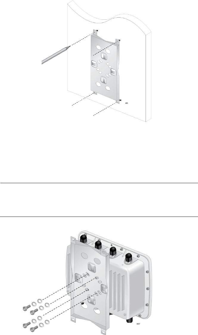
3. Using the mounting base as a template, mark four holes with a pencil.
See Figure 13.
c
Figure 13. Mounting Base Hole Dimensions
4. Pre-drill the marked locations on the wall.
5. Attach the mounting base to the access point with the screws using a
Phillips-head screwdriver. See Figure 14.
Note
Attach the ground cable to the access point before attaching the
mounting base. See “Attaching the Ground Cable to the Access
Point” on page 30.
Figure 14. Attaching the Mounting Base to the Access Point
Draft 5 on February 14, 2019
Chapter 2: Installing the Access Point
39
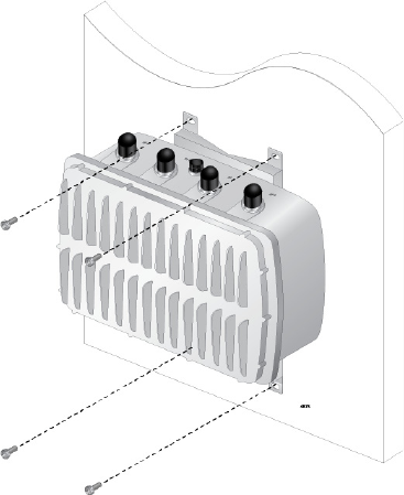
6. Install the four sets of bolts and wall anchors into the holes you made
in Step 4.
7. Attach the nuts and washers to the bolts in the wall to install the access
point unit. SeeFigure 15.
Figure 15. Installing to the Wall Using Bolts
Draft 5 on February 14, 2019
AT-TQ5403e Outdoor Wireless Access Point Installation Guide
40
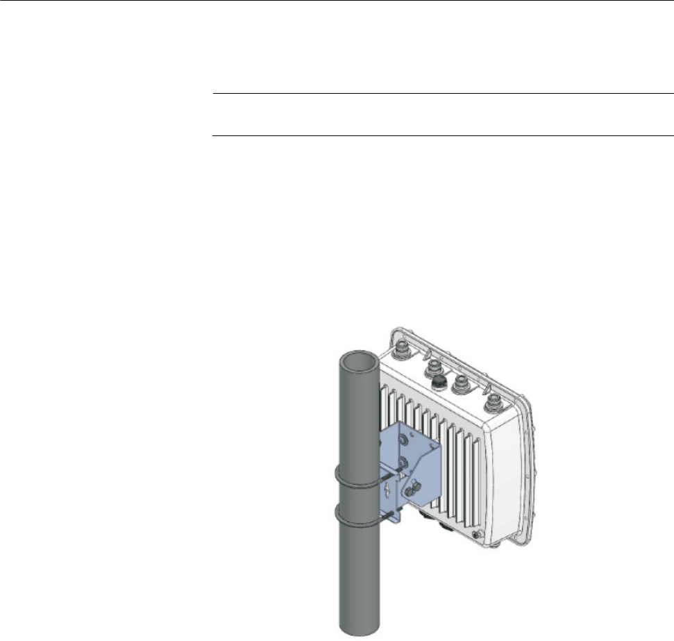
Installing the Access Point on a Pole
The AT-TQ5403e access point can be mounted on a vertical pole or
horizontal pole. see Figure 16.
Note
The pole mount bracket is angle-adjustable.
Guidelines for
Pole Installation
Review the following guidelines before installing the access point on a
wall:
The pole mount bracket has two hex-head bolts that allow you to
adjust the position of the access point upward or downward.
The access point must be installed the front panel down as shown in
Figure 16.
Figure 16. Pole Installation of the Access Point
What to Prepare
for Pole
Installation
You need the following items to install the access point on a pole:
AT-TQ5403e Access Point
Pole mount bracket
Four sets of screws, spring washers, and washers for the pole
mount bracket
Two U-bolds
Phillips-head screwdriver
Draft 5 on February 14, 2019
Chapter 2: Installing the Access Point
41
Note
A Phillip-head screwdriver is not included in the shipping box.
10mm socket and ratchet or adjustable wrench (for adjusting the
position of the access point)
Installing the
Access Point on a
Pole
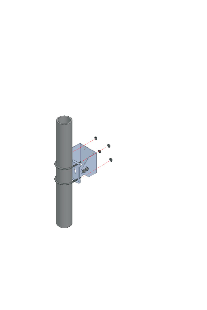
To install the access point on a pole, perform the following procedure:
1. Review “Guidelines for Pole Installation” on page 40.
2. Attach the pole mount brackets to the pole with two U-bolds. See
Figure 17.
Figure 17. Attaching the Pole-Mount Brackets to the Pole
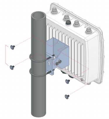
3. Attach the access point to the pole-mount bracket with the screws
using a Phillips-head screwdriver. See Figure 18.
Note
Attach the ground cable to the access point before attaching the
mounting base to the access point. Refer to “Attaching the Ground
Cable to the Access Point” on page 30.
Draft 5 on February 14, 2019
AT-TQ5403e Outdoor Wireless Access Point Installation Guide
42
Figure 18. Attaching the Access Point to the Pole-Mount Brackets
Adjusting the
Position Upward
or Downward
If you want to position the access point upward or downward, do the
following procedures:
1. Loose two bolts located on the sides of the pole mount brackets using
an adjustable wrench or a 10mm socket and ratchet.
2. Adjust the angle of the access point upward or downward.
3. Tighten the bolts.
Draft 5 on February 14, 2019

Chapter 2: Installing the Access Point
43
Starting the Initial Management Session on the Access Point
The wireless access point firmware includes a DHCP client. The default
setting for the client is enabled. When you power on the access point for
the first time, it queries the subnet on the LAN port for a DHCP server. If a
DHCP server responds to its query, the unit uses the IP address the server
assigns to it. If there is no DHCP server, the access point uses the default
IP address 192.168.1.230.
Note
The initial management session of the access point has to be
conducted through the LAN port because the default setting for the
radios is off.
To start the management session, perform the following procedure:
1. Connect the access point to a PoE switch.
If your network has VLANs, the access point must be connected to a
port on the PoE switch that belongs to the same VLAN as the port
where your management PC is connected.
You may need to access the management software on the PoE switch
to list the VLANs and their port assignments. For example, if the
access point is connected to a port that is a member of the Sales
VLAN, your management PC must be connected to a port that is also a
member of that VLAN. If your network is small and does not have
VLANs or routers, you may connect your management PC to any port
on the PoE switch.
2. Start the web browser on your management PC.
3. Perform the one of the following steps:
If your network does not have a DHCP server, change the IP
address on your management PC to 192.168.1.n. The n is any
number from 1 to 254, except 230. Then, enter the default address
192.168.1.230 in the URL field of the web browser.
If your network has a DHCP server, enter the IP address that the
DHCP server assigned ti the access point.
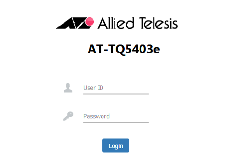
The login page appears. See Figure 19 on page 44.
Draft 5 on February 14, 2019
AT-TQ5403e Outdoor Wireless Access Point Installation Guide
44
.
Figure 19. Login Window
4. Enter “manager” for the username and “friend” for the password.
The username and password are case-sensitive.
Draft 5 on February 14, 2019
Chapter 2: Installing the Access Point
45
Setting the Country Setting
You should set the country setting during the initial management session
of the access point to ensure that the device operates in compliance with
the codes and regulations of your region or country.
Note
The non-US model of this product has a country code setting that
must be set during the initial management session of the unit. The
setting ensures that the unit operates in compliance with the laws
and regulations of your country or region.
For the US model, the country code is preset and cannot be
changed. Per FCC regulations, the country code setting for all WiFi
products marketed in the US must be fixed to US operational
channels only.
To set the country setting, perform the following procedure:
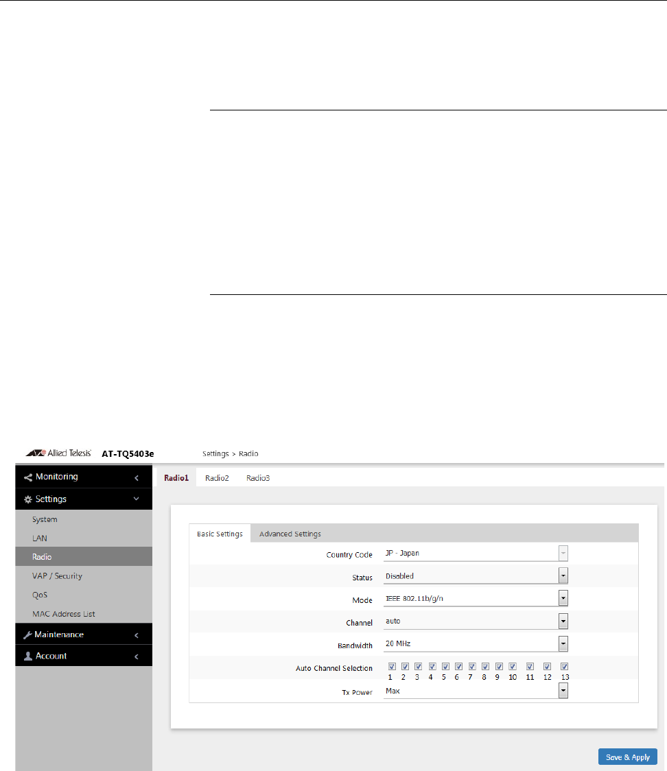
1. Select Settings > Radio from the menu on the left,
The access point displays the Basic Settings for Radio 1. See
Figure 20.
Figure 20. Basic Settings for Radio1
Draft 5 on February 14, 2019

AT-TQ5403e Outdoor Wireless Access Point Installation Guide
46
2. Select the Country pull-down menu and select your country or region.
Note
If the Country pull-down menu is deactivated and cannot be
changed, the country parameter was set when the unit was
manufactured. If the setting is not correct for your country or region,
contact your Allied Telesis sales representative for assistance.
The access point displays a confirmation prompt.
3. Click OK to change the country setting or Cancel to cancel the
procedure.
If you click OK, the access point changes the country setting and
disables all radios on the access point.
Note
This procedure does not require clicking the Save & Apply button.
Allied Telesis recommends rebooting the access point after changing
the country settings. To reboot the unit, either power off on the unit or
continue with these steps:
4. From the Maintenance menu, select Reboot.
5. Click the Reboot button.
6. When the access point displays a confirmation prompt, click OK to
reboot the unit or Cancel to cancel the procedure.
7. To resume managing the unit, wait for it to complete initializing its
management software and then start a new management session.
Note
For more instructions on how to configure the features of the access
point, see a User Guides for this access point..
Draft 5 on February 14, 2019

47
Appendix A
Technical Specifications and Statements
This appendix contains the following sections:
“Physical Specifications”
“Power Specifications”
“Environmental Specifications” on page 48
“Antenna Specifications” on page 48
“LAN Port” on page 49
“Safety and Electromagnetic Emissions Certifications” on page 51
“Operation Frequency Information” on page 52
“IC Statements” on page 53
“Europe - EU Declaration of Conformity” on page 55
Physical Specifications
Power Specifications
Table 5. AT-TQ5403e Physical Specifications
Dimensions (W x D x H) 260 mm x 230 mm x 85 mm
(8.6 in. x 9.8 in. x 2.2 in.)
Weight of the device
Weight of the device with antennas
Weight of the device with antennas
and wall mount
2.8 kg (6.2 lb.)
4.o kg (8.8 lb.)
4.4 kg (9.7 lb.)
Table 6. AT-TQ5403e Maximum Power Consumption
AT-TQ5403e 15.8 watts
Draft 5 on February 14, 2019

AT-TQ5403e Outdoor Wireless Access Point Installation Guide
48
Environmental Specifications
Antenna Specifications
This radio transmitter [3336D-TQ5403E] has been approved by
Innovation, Science and Economic Development Canada to operate with
the antenna types listed below, with the maximum permissible gain
indicated. Antenna types not included in this list that have a gain greater
than the maximum gain indicated for any type listed are strictly prohibited
for use with this device.
Le présent émetteur radio [3336D-TQ5403E] a été approuvé par
Innovation, Sciences et Développement économique Canada pour
fonctionner avec les types d'antenne énumérés ci dessous et ayant un
gain admissible maximal. Les types d'antenne non inclus dans cette liste,
et dont le gain est supérieur au gain maximal indiqué pour tout type
figurant sur la liste, sont strictement interdits pour l'exploitation de
l'émetteur.
Table 7. Environmental Specifications
Operating Temperature of the
Access Point
-40° C to 65° C (-40° F to 149° F)
Storage Temperature -40° C to 80° C (-40° F to 176° F)
Operating Humidity 5% to 95% non-condensing
Storage Humidity 5% to 95% non-condensing
Altitude of operation Up to 3,000m (9,9843 ft)
Table 8. Antenna Specifications
Antenna type Dipole
Antenna Connector N-type
Table 9. Frequency and Gain
Frequency (MHz) 2400 ~ 2483.5 5150~5250 5250~5350 5470~5725 5725~5850
Gain (dBi) 5.2 6.91 6.72 6.34 7.08
Draft 5 on February 14, 2019
Appendix A: Technical Specifications and Statements
49
LAN Port
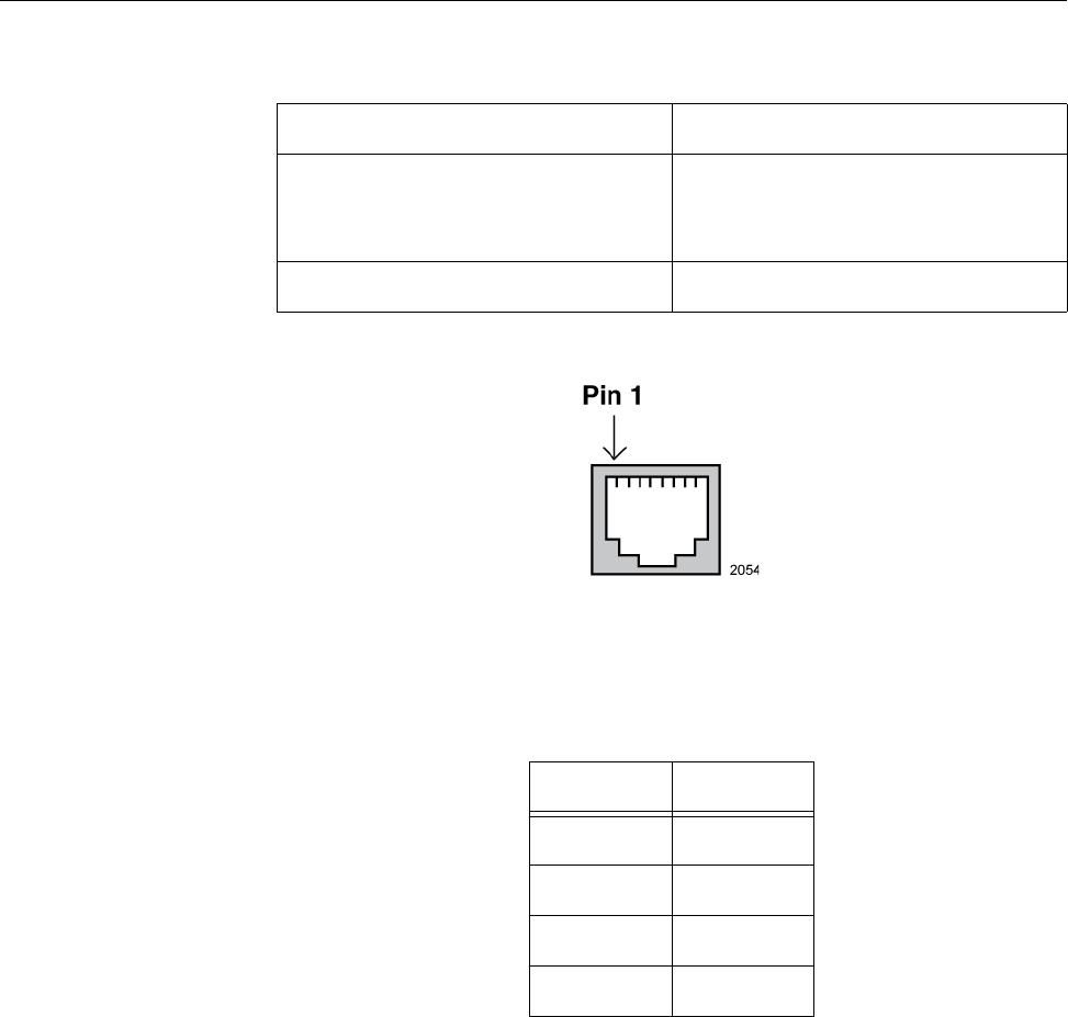
Figure 21 illustrates the pin layout of the LAN port.
Figure 21. Pin Layout for the RJ45 Connector on the LAN Port
Table 11 lists the pin signals when the port is operating in the MDI
configuration at 10 or 100 Mbps.
Table 10. LAN Port Specifications
Connector RJ45
Standards IEEE 802.3 (10Base-T)
IEEE 802.3u (100Base-TX)
IEEE 802.3ab (1000Base-T)
PoE standard IEEE 802.3at (class 4)
Table 11. MDI Pin Signals (10Base-T or 100Base-TX)
Pin Signal
1TX+
2TX-
3RX+
6RX-
Draft 5 on February 14, 2019

AT-TQ5403e Outdoor Wireless Access Point Installation Guide
50
Table 12 lists the pin signals for the MDI-X configuration at 10 or 100
Mbps.
Table 13 lists the pin signals when the LAN port is operating at 1000
Mbps.
Table 12. MDI-X Pin Signals (10Base-T or 100Base-TX)
Pin Signal
1RX+
2RX-
3TX+
6TX-
Table 13. 1000Base-T Connector Pinouts
Pin Pair Signal
1 1 TX and RX
2 1 TX and RX-
32TX and RX+
43TX and RX+
5 3 TX and RX-
6 2 TX and RX-
74TX and RX+
8 4 TX and RX-
Draft 5 on February 14, 2019

Appendix A: Technical Specifications and Statements
51
Safety and Electromagnetic Emissions Certifications
Table 14. Safety and Electromagnetic Emissions Certificates
Standard
Compliance
RoHs compliant
European Union RoHS (Directive 2011/65/EU of
the European Parliament and of the Council of 8
June 2011 on the restriction of the use of certain
hazardous substances in electrical and electronic
equipment.)
Certificates CE
FCC/IC
RCM
Wi-Fi CERTIFIED
Emissions (EMI) FCC part15 Subpart B Class B
CISPR32 Class B
AS/NZS CISPR 32
RED EN55032 Class B
RCM
VCCI Class B
Immunity (EMS) RED EN55024
EN61000-3-2
EN61000-3-3
Safety UL 62368-1 2nd Edition
IEC 62368-1 2nd Edition
CE EN 62368-1 2nd Edition
Draft 5 on February 14, 2019

AT-TQ5403e Outdoor Wireless Access Point Installation Guide
52
Operation Frequency Information
√:usableband
N/A:disabledband
Table 15. Operation Frequency
2.4GHz 5150~5250GHz 5250~5350GHz 5470~5725GHz 5725~5850GHz
Indoor Outdoor Indoor Outdoor Indoor Outdoor Indoor Outdoor Indoor Outdoor
CE √√√N/A √N/A √√N/A N/A
FCC √√√√√√√√√√
TELEC √√√N/A √N/A √√N/A N/A
RCM √√√N/A √N/A √√√√
IC √√√N/A √√√√√√
Draft 5 on February 14, 2019

Appendix A: Technical Specifications and Statements
53
IC Statements
This device contains license-exempt transmitter(s)/receiver(s) that comply
with Innovation, Science and Economic Development Canada’s license-
exempt RSS(s). Operation is subject to the following two conditions:
(1) This device may not cause interference.
(2) This device must accept any interference, including interference that
may cause undesired operation of the device.
L’émetteur/récepteur exempt de licence contenu dans le présent appareil
est conforme aux CNR d’Innovation, Sciences et Développement
économique Canada applicables aux appareils radio exempts de licence.
L’exploitation est autorisée aux deux conditions suivantes :
(1) L’appareil ne doit pas produire de brouillage;
(2) L’appareil doit accepter tout brouillage radioélectrique subi, même si
le brouillage est susceptible d’en compromettre le fonctionnement.
IC Radiation
Exposure
Statement
This equipment complies with IC RSS-102 radiation exposure limit set
forth for an uncontrolled environment. This equipment should be installed
and operated with minimum distance 20cm between the radiator and your
body.
Déclaration
d’exposition à la
radiation
Cet équipement respecte les limites d’exposition aux rayonnements IC
définies pour un environnement non contrôlé. Cet équipement doit être
installé et mis en marche à une distance minimale de 20cm qui sépare
l’élément rayonnant de votre corps.
L’émetteur ne doit ni être utilisé avec une autre antenne ou un autre
émetteur ni se trouver à leur proximité.
Caution (i) the device for operation in the band 5150-5250 MHz is only for indoor
use to reduce the potential for harmful interference to co-channel mobile
satellite systems;
(ii) the maximum antenna gain permitted for devices in the bands 5250-
5350 MHz and 5470-5725 MHz shall comply with the e.i.r.p. limit; and
(iii) the maximum antenna gain permitted for devices in the band 5725-
5825 MHz shall comply with the e.i.r.p. limits specified for point-to-point
and non point-to-point operation as appropriate.
(iv) Users should also be advised that high-power radars are allocated as
primary users (i.e. priority users) of the bands 5250-5350 MHz and 5650-
5850 MHz and that these radars could cause interference and/or damage
to LE-LAN devices.
Draft 5 on February 14, 2019
AT-TQ5403e Outdoor Wireless Access Point Installation Guide
54
Avertissement Le guide d’utilisation des dispositifs pour réseaux locaux doit inclure des
instructions précises sur les restrictions susmentionnées, notamment:
(i) les dispositifs fonctionnant dans la bande 5150-5250 MHz sont
réservés uniquement pour une utilisation à l’intérieur afin de réduire les
risques de brouillage préjudiciable aux systèmes de satellites mobiles
utilisant les mêmes canaux;
(ii) le gain maximal d’antenne permis pour les dispositifs utilisant les
bandes 5250-5350 MHz et 5470-5725 MHz doit se conformer à la limite
de p.i.r.e.;
(iii) le gain maximal d’antenne permis (pour les dispositifs utilisant la
bande 5725-5825 MHz) doit se conformer à la limite de p.i.r.e. spécifiée
pour l’exploitation point à point et non point à point, selon le cas.
(iv) De plus, les utilisateurs devraient aussi être avisés que les utilisateurs
de radars de haute puissance sont désignés utilisateurs principaux (c.-àd.,
qu’ils ont la priorité) pour les bandes 5250-5350 MHz et 5650-5850MHz et
que ces radars pourraient causer du brouillage et/ou des dommages aux
dispositifs LAN-EL.
Professional
Installation
Instruction
Installation personal
This product is designed for specific application and needs to be installed
by a qualified personal who has RF and related rule knowledge. The
general user shall not attempt to install or change the setting.
Instructions
d'installation
professionnelle:
Installation personnelle
Ce produit est destine a un usage specifique et doit etre installe par un
personnel qualifie maitrisant les radiofrequences et les regles s'y
rapportant. L'installation et les reglages ne doivent pas etre modifies par
l'utilisateur final.
Draft 5 on February 14, 2019

Appendix A: Technical Specifications and Statements
55
Europe - EU Declaration of Conformity
Hereby, Allied Telesis declares that the radio equipment type
[AT-TQ5403e] is in compliance with Directive 2014/53/EU.
Operating
Frequencies and
Maximum
Transmission
Power Levels
The operating frequencies and maximum transmission power levels for
wireless devices operated in the EU are listed below:
Non-Beamforming:
- 2412-2472 MHz: 19.07 dBm (80.81mW)
- 5180-5240 MHz: 22.43 dBm (174.82mW)
- 5260-5320 MHz: 22.52 dBm (178.79mW)
- 5500-5700 MHz: 29.12 dBm (817.50mW)
Beamforming:
- 2412-2472 MHz: 19.16 dBm (82.44mW)
- 5180-5240 MHz: 22.32 dBm (170.75mW)
- 5260-5320 MHz: 22.75 dBm (188.33mW)
- 5500-5700 MHz: 29.05 dBm (803.06mW)
Draft 5 on February 14, 2019