Alltek Marine Electronics AIS-A701 AIS Class A Transponder User Manual Users manual
Alltek Marine Electronics Corporation AIS Class A Transponder Users manual
UserManual.wiki
>
Alltek Marine Electronics
>
AIS A701 User Manual
Users manual
Navigation menu
Upload a User Manual
Namespaces
Wiki Guide
HTML
PDF
Info
Views
User Manual
Discussion / Help
Navigation

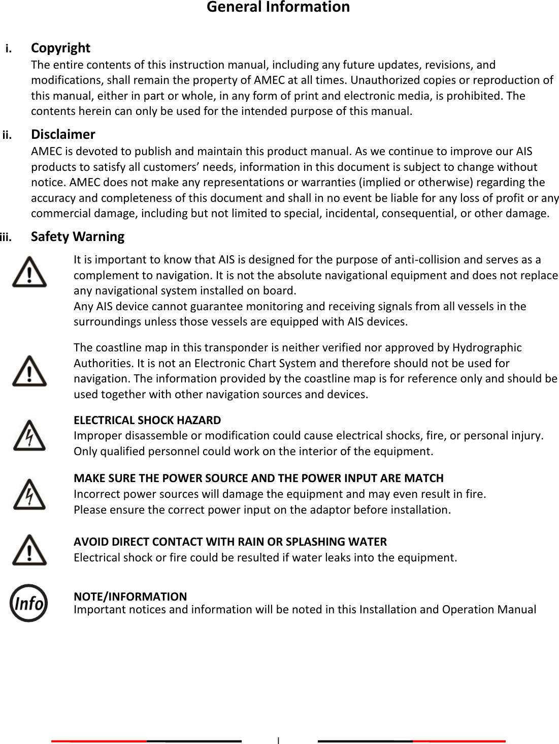
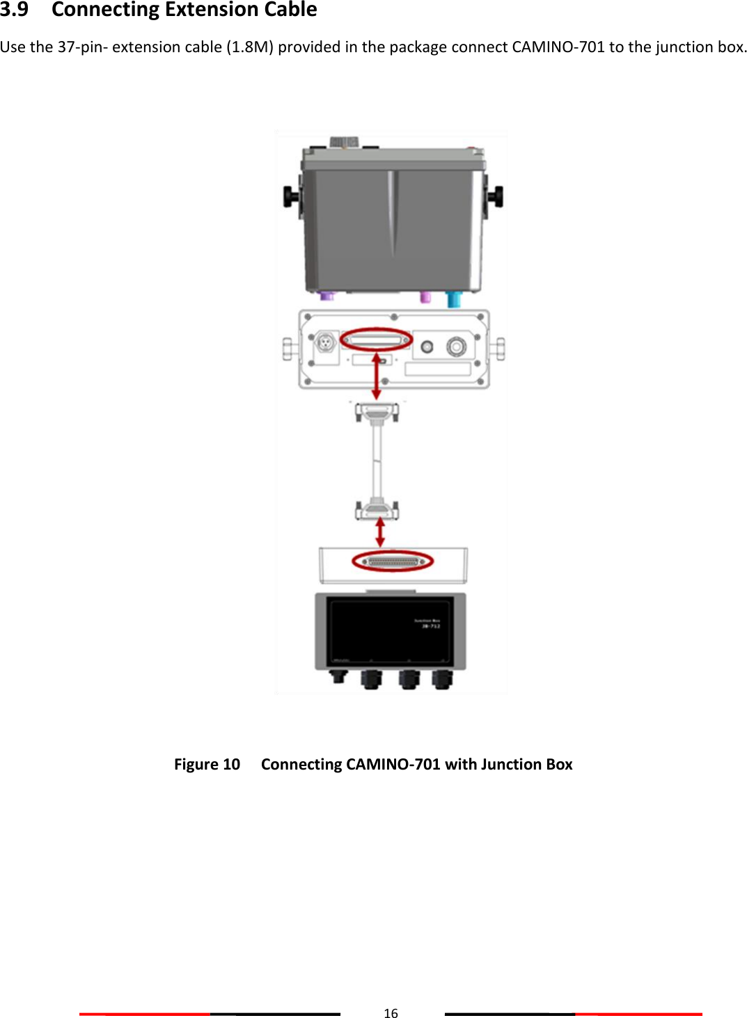
![17 3.10 Configuring CAMINO-701 The following items must be completed before initial configuration. 1. Ensure VHF and GPS antennas are well connected to the transponder main unit. 2. Ensure the 37-pin-connector extension cable is well connected from the transponder main unit to the junction box. 3. Ensure the power cable is well connected and supplied with stable voltage/current power source. 4. Ensure applicable external devices are well connected through the junction box. 3.10.1 Initial Configuration The initial configuration, particular, MMSI (Maritime Mobile Service Identity) number must be done before operation. The following initial configuration is required: 1. Setup 1: MMSI should be correctly programmed. Figure 11 Built-in Test 2. Step 2: Press MENU and select main menu item SHIP SETTING. (Password required, default is “0000”) Power…………………..…….…………[PASS] Flash..…………………..…….…………[PASS] Built-in Test Transmission inhibited! Only Receiving Function available! Set MMSI right now? YES NO MMSI unregistered](https://usermanual.wiki/Alltek-Marine-Electronics/AIS-A701/User-Guide-1979443-Page-23.png)
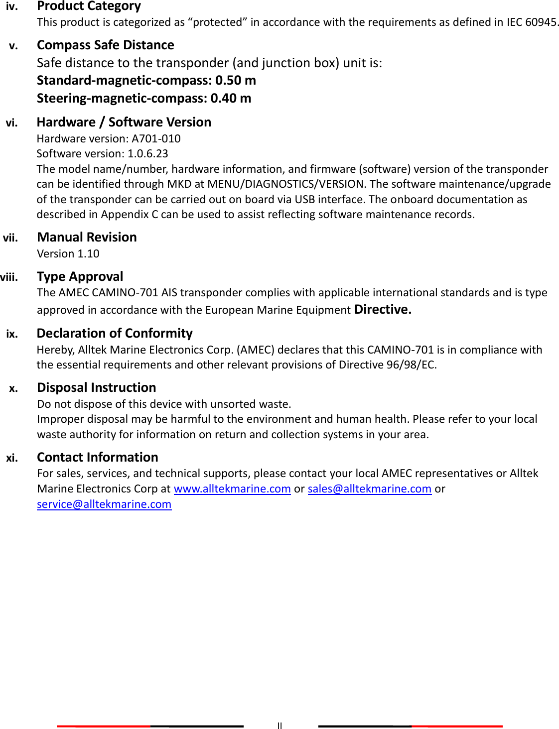
![18 A. Setup call sign, ship name, ship type, external/internal GPS antenna position in OWN SHIP. Figure 12 Own Ship B. If IMO identification number is applicable, select main menu item Change MMSI/IMO to setup IMO number. Figure 13 IMO Setting For more information please refer to 4.7 SHIP SETTING. IMO SETTING 2013/01/17 07:18:11 IMO [000000000] Targets Received: 10 MENU MESSAGES NAV. STATUS SHIP SETTING TRANSCEIVER SYS CONFIG DIAGNOSTICS MAIN MENU OWN SHIP VOYAGE CPA/TCPA CHANGE MMSI/IMO RETRY TIMES SHIP SETTING 2013/01/17 07:18:11 Dangerous Targets :0](https://usermanual.wiki/Alltek-Marine-Electronics/AIS-A701/User-Guide-1979443-Page-24.png)
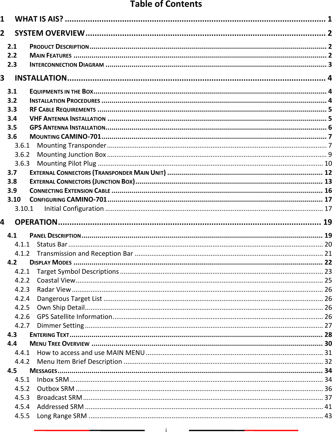
![27 4.2.7 Dimmer Setting Press the button “DIM” to enter the dimmer setting page. Figure 19 Dimmer Setting Button Description Knob (Turn left/right) Adjust screen brightness (decrease/increase) Knob (Press) Save and leave the page DIM Restore screen brightness to default setting (100) MENU、ESC Leave the page without saving CUSTOMIZE 2013/01/17 07:18:11 Dangerous Targets :0 DIMMER LEVEL [ 100 ] Lo Hi](https://usermanual.wiki/Alltek-Marine-Electronics/AIS-A701/User-Guide-1979443-Page-33.png)
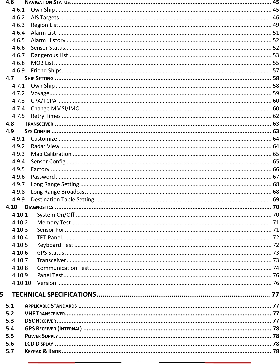
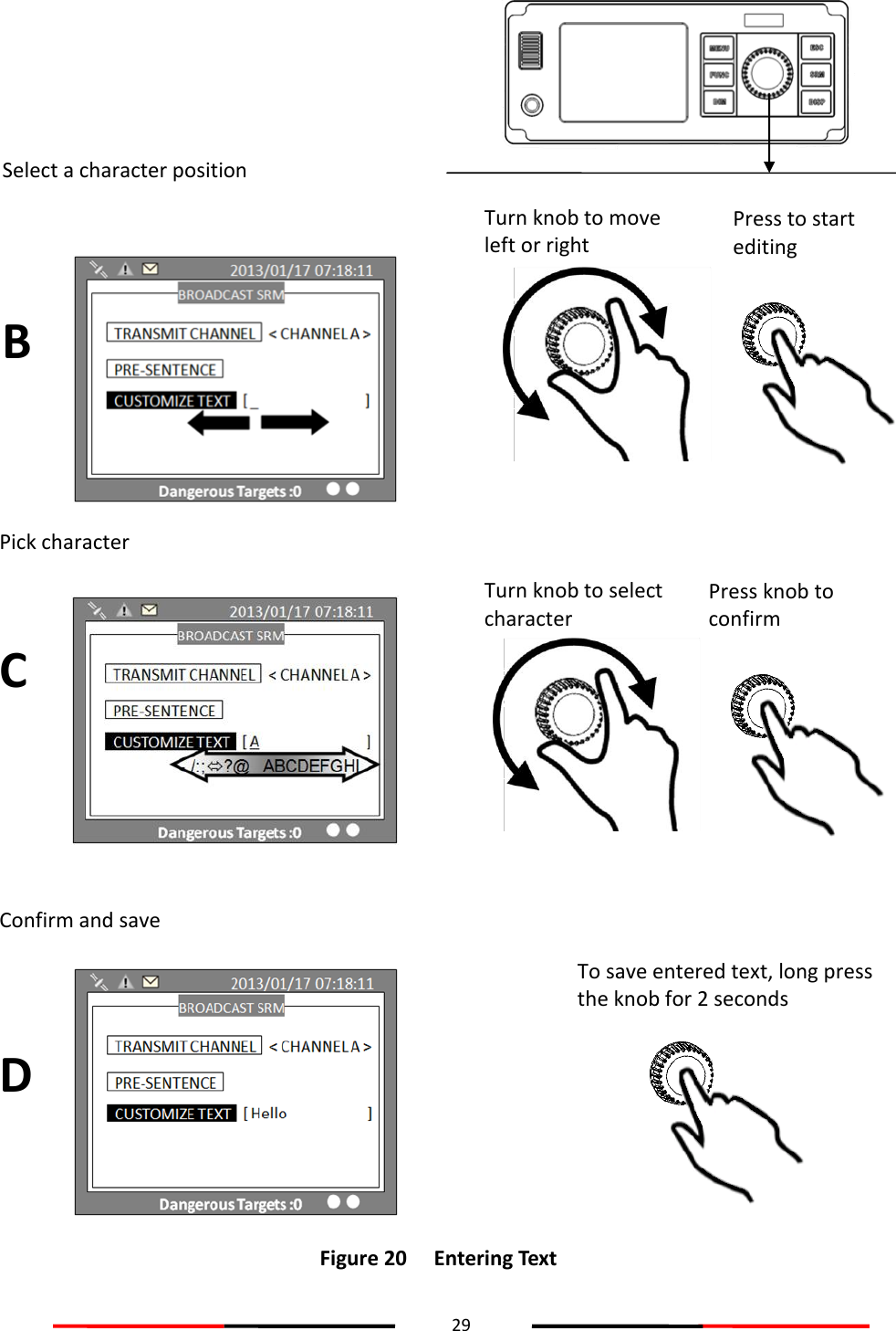
![28 4.3 Entering Text The knob on the front control panel is used for entering and editing text. The figures below show the text entering procedures. A. Turn the knob to traverse the menu items up or down. Once selected, press the knob to select the item for text entering. B. Select a character position to edit. Turn the knob to move the cursor left or right and press the knob to confirm the position. C. System is now in character selection mode as the cursor position is highlighted. Turn the knob to pick an available character and press the knob for character selection. A B C D E F G H I J K L M N O P Q R S T U V W X Y Z 0 1 2 3 4 5 6 7 8 9 [ \ ] ^ _ ! “ # $ & ‘ ( ) * + , - . / : ; < = > ? @ Space is first character for selection D. Use steps B and C to finish entering all needed characters. To confirm and save, press down the knob and hold for 2 seconds. A Turn knob to move up or down Press to enter Traverse menu](https://usermanual.wiki/Alltek-Marine-Electronics/AIS-A701/User-Guide-1979443-Page-34.png)
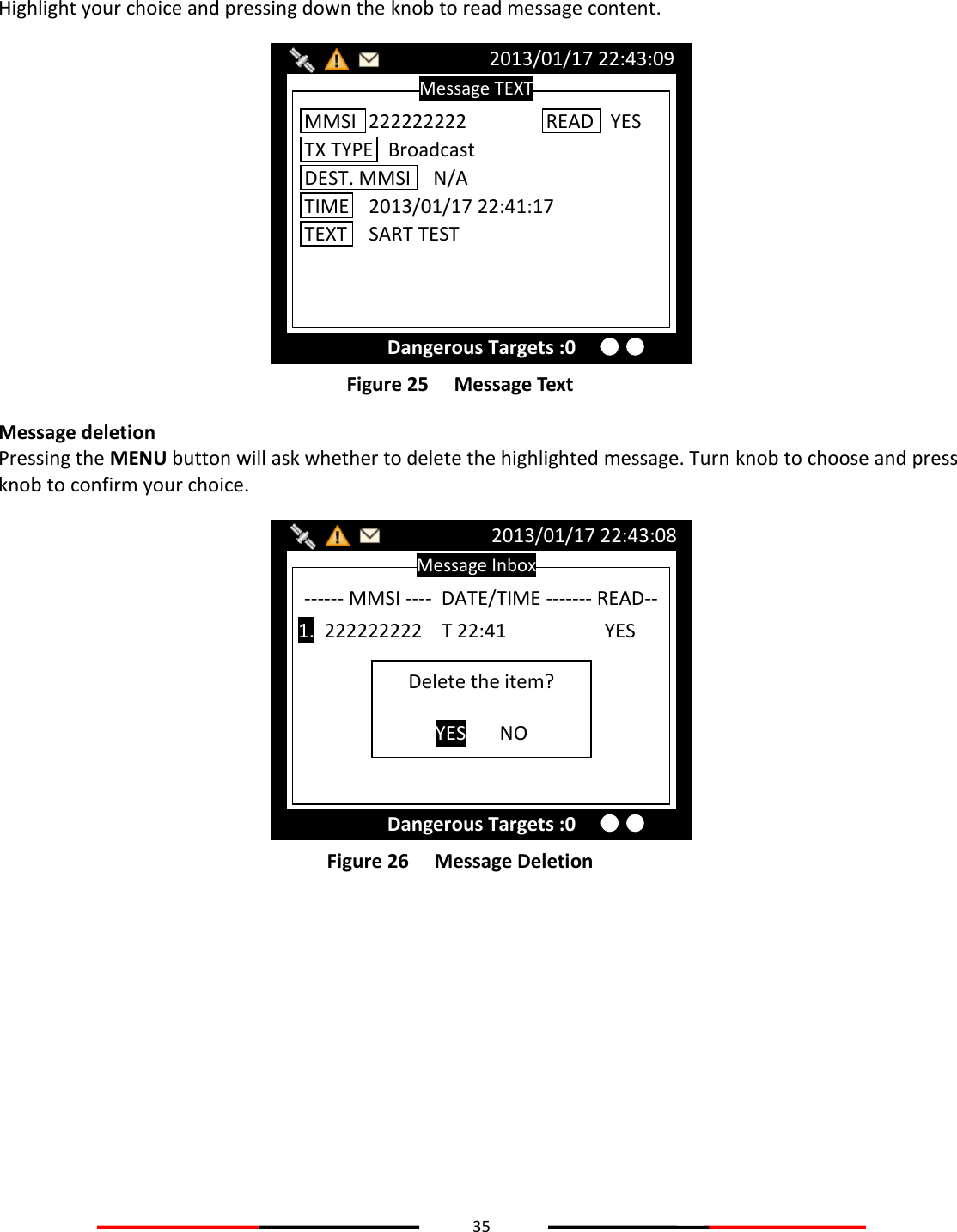
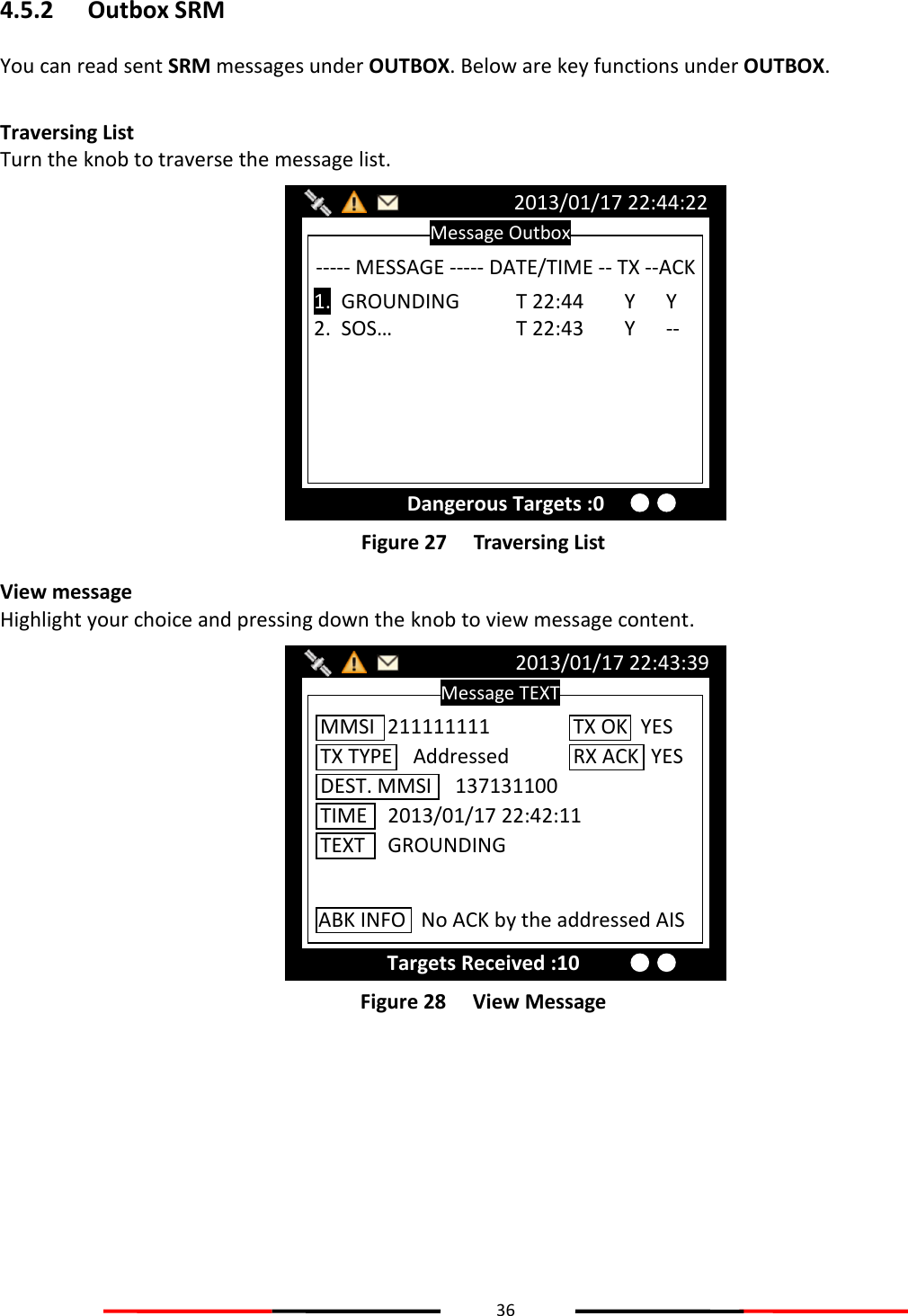
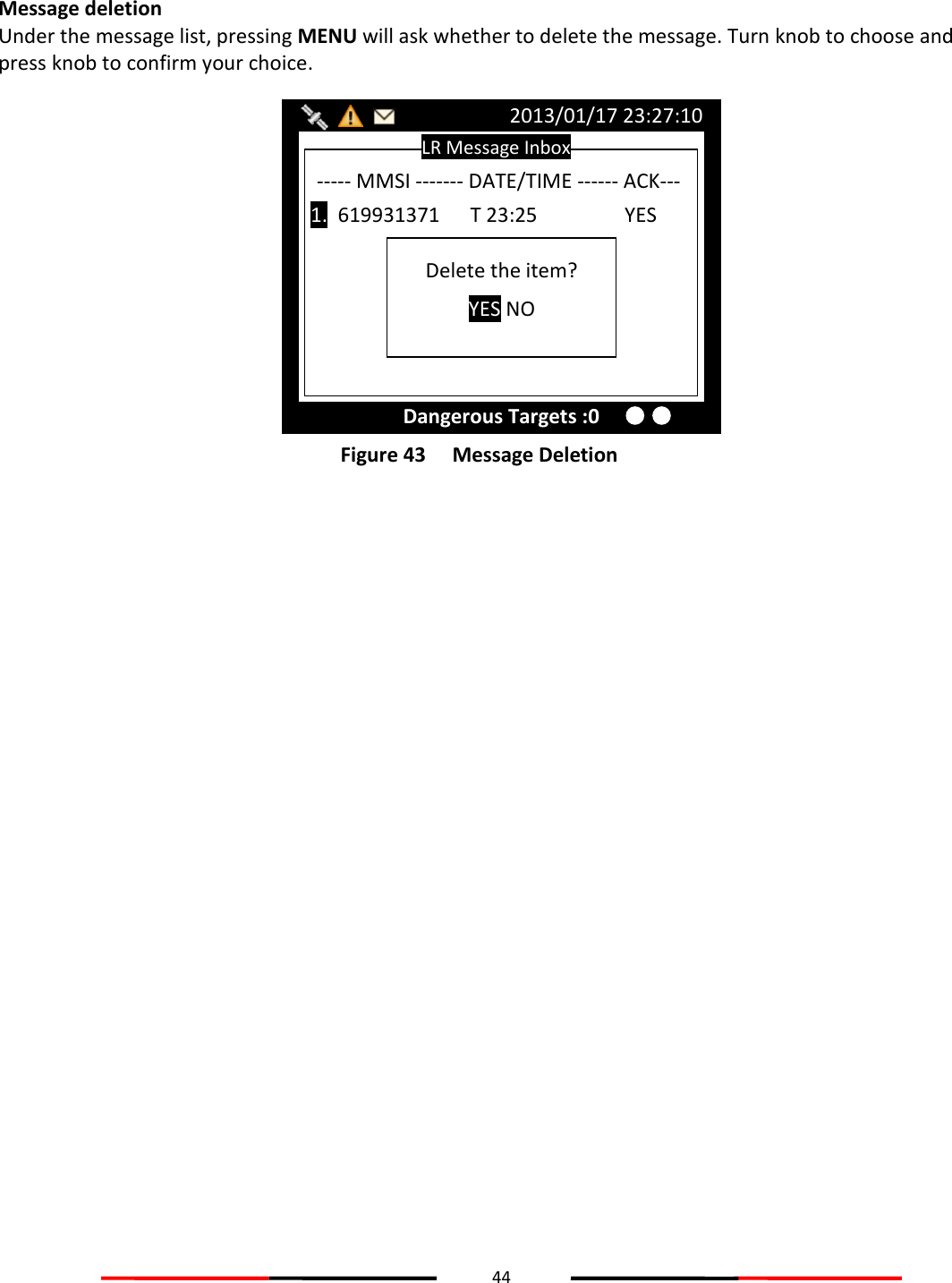
![37 Message deletion Pressing the MENU button will ask whether to delete the highlighted message. Turn knob to choose and press MENU to confirm the decision. Figure 29 Message Deletion 4.5.3 Broadcast SRM Use this menu to send a Pre-defined or custom message. Turn the knob to traverse all available option. Maximum length for the customized message is 90 characters. Figure 30 Broadcast SRM BROADCAST SRM 2013/01/17 07:18:11 Dangerous Targets :0 CUSTOMIZE TEXT [ ] [ ] [ ] TRANSMIT CHANNEL < ALTERNATE > Message Outbox 2013/01/17 22:44:22 Dangerous Targets :0 ----- MESSAGE ----- DATE/TIME -- TX --ACK 1. GROUNDING T 22:44 Y Y 2. SOS… T 22:43 Y -- Delete the item? YES NO](https://usermanual.wiki/Alltek-Marine-Electronics/AIS-A701/User-Guide-1979443-Page-43.png)
![38 Selecting SRM channel SRM channel selection is the first option in the screen. Highlight it and press the knob to enter the option. Turn the knob to change the setting. Figure 31 Select SRM Channel Once finish the settings, press the knob again to return. Figure 32 Finish Setting BROADCAST SRM 2013/01/17 07:18:11 Dangerous Targets :0 CUSTOMIZE TEXT [ ] [ ] [ ] TRANSMIT CHANNEL < ALTERNATE > BROADCAST SRM 2013/01/17 07:18:11 Dangerous Targets :0 CUSTOMIZE TEXT [ ] [ ] [ ] TRANSMIT CHANNEL < ALTERNATE >](https://usermanual.wiki/Alltek-Marine-Electronics/AIS-A701/User-Guide-1979443-Page-44.png)
![39 Using Predefined-Sentence You may use PRE-SENTENCE option to select a pre-defined message sentences or a customized text. Press the knob to enter and turn the knob to switch sentence selections, and then press the knob to confirm. To use a customized sentence, turn selection to <Other>, and remember to enter you customized text at the CUSTOMIZE TEXT option. Entering SRM customized text Press the knob to enter text input mode, then turn the knob to traverse character position on the text. Figure 33 SRM Customized Text Choose a text location, and then press the knob to enter text input mode. Turn the knob to select a character, and then press the knob to confirm and to return. Repeat these steps till all desired characters are entered. Figure 34 Enter Customized Text BROADCAST SRM 2013/01/17 07:18:11 Dangerous Targets :0 CUSTOMIZE TEXT [A ] [ ] [ ] TRANSMIT CHANNEL < CHANNEL A > BROADCAST SRM 2013/01/17 07:18:11 Dangerous Targets :0 CUSTOMIZE TEXT [ ] [ ] [ ] TRANSMIT CHANNEL < CHANNEL A >](https://usermanual.wiki/Alltek-Marine-Electronics/AIS-A701/User-Guide-1979443-Page-45.png)
![40 When finished, press ESC to return to BROADCAST SRM menu. Figure 35 Finish Customized Text When done with all settings, pressing MENU or ESC to leave and the system will ask whether to send the message. Select OK to send, CANCEL to cancel and return to main menu. Figure 36 Send Message BROADCAST SRM 2013/01/17 07:18:11 Dangerous Targets :0 CUSTOMIZE TEXT [A ] [ ] [ ] TRANSMIT CHANNEL < CHANNEL A > Send Message? OK CANCEL BROADCAST SRM 2013/01/17 07:18:11 Dangerous Targets :0 CUSTOMIZE TEXT [A ] [ ] [ ] TRANSMIT CHANNEL < CHANNEL A >](https://usermanual.wiki/Alltek-Marine-Electronics/AIS-A701/User-Guide-1979443-Page-46.png)
![41 4.5.4 Addressed SRM Press the knob button on ADDRESSED SRM will remind to select a target to send. Figure 37 Addressed SRM Pressing the knob will bring up the vessel list. Figure 38 AIS Target List AIS TARGET LIST 2013/01/17 22:44:22 Dangerous Targets :0 [013] - NAME/MMSI ---ET-- BRG(°) -- RNG(NM) RNG 1. 211111161 1s 321 39.54 2. 211111561 1s 314 31.96 3. TEST05 1s 143 19.22 4. TEST10 2s 8 52.66 5. TEST03 1s 293 20.45 6. TEST06 1s 30 30.84 7. TEST08 2s 342 58.81 8. 211111461 3s 274 39.97 9. 211111161 3s 321 39.54 10. TEST02 4s 325 91.62 MENU MESSAGES NAV. STATUS SHIP SETTING TRANSCEIVER SYS CONFIG DIAGNOSTICS MAIN MENU INBOX OUTBOX BROADCAST SRM ADDRESSED SRM LR INBOX MESSAGE 2013/01/17 07:18:11 Dangerous Targets :0 Select Target OK Set SRM Alarm](https://usermanual.wiki/Alltek-Marine-Electronics/AIS-A701/User-Guide-1979443-Page-47.png)
![42 Select the target vessel by pressing the knob to customize SRM sending. Maximum length for the customized message is 85 characters. Figure 39 Customize SRM When changing Destination MMSI, choose a text location, and then press the knob to enter text input mode. Turn the knob to select a character, and then press the knob to confirm and to return. Repeat these steps till all desired characters are entered. When done with all settings, press MENU or ESC to leave. The system will ask whether to send the message. Select OK to send, CANCEL to cancel and return to main menu. Figure 40 Send Message ADDRESSED SRM 2013/01/17 07:18:11 Dangerous Targets :0 TRANSMIT CHANNEL <ALTERNATE> DESTN. MMSI [ 222222222 ] CUSTOMIZE TEXT [A ] [ ] [ ] [ ] Send Message? OK CANCEL ADDRESSED SRM 2013/01/17 07:18:11 Dangerous Targets :0 TRANSMIT CHANNEL <ALTERNATE> DESTN. MMSI [ 222222222 ] CUSTOMIZE TEXT [ ] [ ] [ ]](https://usermanual.wiki/Alltek-Marine-Electronics/AIS-A701/User-Guide-1979443-Page-48.png)
![45 4.6 Navigation Status Figure 44 Navigation Status 4.6.1 Own Ship This option displays the full information on your ship, including both dynamic and static data. Turning the knob, can view dynamic and static information alternatively. Static data Figure 45 Static Data OWN SHIP <1/2> 2013/01/17 22:43:39 Dangerous Targets :0 NAME AMEC09 CALL CS09 MMSI 211111111 [CLASS A] NAV. Under way using engine LON 121°45’00”E LAT 025°09’25”N SOG 12.00Kn COG 298.0° ROT N/A 000/023 EPFS GPS RNG Own Ship BRG Own Ship CPA 5 NM (set) HDG N/A TCPA 10 min (set) P.A. Hi Manoeuvre Ind. not available RAIM In use TX POWER 12.5 W MENU MESSAGES NAV. STATUS SHIP SETTING TRANSCEIVER SYS CONFIG DIAGNOSTICS MAIN MENU OWN SHIP AIS TARGETS REGION LIST ALARM LIST ALARM HISTORY SENSOR STATUS NAV. STATUS 2013/01/17 07:18:11 Dangerous Targets :0](https://usermanual.wiki/Alltek-Marine-Electronics/AIS-A701/User-Guide-1979443-Page-51.png)
![46 Dynamic data Figure 46 Dynamic Data 4.6.2 AIS Targets This option displays all receive AIS messages of other boats. It can show their dynamic or static information. Turn the knob to select an AIS target. Figure 47 AIS Targets AIS TARGET LIST 2013/01/17 22:44:22 Dangerous Targets :0 [013] - NAME/MMSI ---ET-- BRG(°) -- RNG(NM) RNG 1. 211111161 1s 321 39.54 2. 211111561 1s 314 31.96 3. TEST05 1s 143 19.22 4. TEST10 2s 8 52.66 5. TEST03 1s 293 20.45 6. TEST06 1s 30 30.84 7. TEST08 2s 342 58.81 8. 211111461 3s 274 39.97 9. 211111161 3s 321 39.54 10. TEST02 4s 325 91.62 OWN SHIP <2/2> 2013/01/17 22:43:39 Dangerous Targets :0 CALL 0001 MMSI 211111111 CARGO N/A or Harmless TYPE Vessel-Pleasure craft NAME AMEC DEST TPE_259 ETA 02/25 01:02 BEAM 87m Pos. Quality Position with RAIM <=10 m 000/023 DRAUGHT 1.0m IMO 111111111 DTE AVAILABLE [CLASS A] A:40m B:41m C: 42m D:45m A B C D LENGTH 81m](https://usermanual.wiki/Alltek-Marine-Electronics/AIS-A701/User-Guide-1979443-Page-52.png)
![47 Press the knob, to read the selected vessel dynamic information. Figure 48 Ship Information Press the knob again to read static information. Figure 49 Static Information SHIP DETAIL <2/2> 2013/01/17 22:43:39 Dangerous Targets :0 CALL TEST12 MMSI 211000601 CARGO N/A or Harmless TYPE Undefined ship type! NAME TEST12 DEST DEST_12 ETA 02/28 01:30 BEAM 64m Pos. Quality Position < 10 m 006/023 DRAUGHT 12.5m IMO 357059601 DTE N/A [CLASS A] A:160m B:34m C: 22m D:42m A B C D LENGTH 194m SHIP DETAIL <1/2> 2013/01/17 22:43:39 Dangerous Targets :0 NAME TEST12 CALL TEST12 MMSI 211000601 [CLASS A] NAV. Under way using engine LON 121°54’59”E LAT 025°12’37”N SOG 26.00Kn COG 350.8° ROT N/A 006/023 EPFS Undefined RNG 10.61NM BRG 80° CPA pass HDG 351.8° TCPA pass P.A. Lo Manoeuvre Ind. not available RAIM Not in use](https://usermanual.wiki/Alltek-Marine-Electronics/AIS-A701/User-Guide-1979443-Page-53.png)
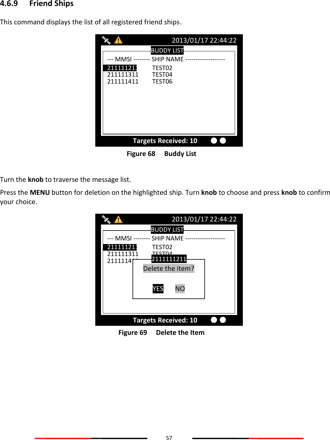
![48 Adding Friend Ship In the list, pressing MENU button will ask whether to add this vessel to your FRIEND SHIP list. Figure 50 Adding Friend Ship Sorting AIS Target List Pressing the FUNC button can sort the list according to vessels’ MMSI, distance, or direction. Figure 51 Sorting AIS Target List In the screenshot above, the block A indicates the current sorting method. By MMSI, in ascending order By direction, in ascending order By distance, in ascending order AIS TARGET LIST 2013/01/17 22:44:22 Dangerous Targets :0 [013] - NAME/MMSI ---ET-- BRG(°) -- RNG(NM) RNG 1. 211111161 1s 321 39.54 2. 211111561 1s 314 31.96 3. TEST05 1s 143 19.22 4. TEST10 2s 8 52.66 5. TEST03 1s 293 20.45 6. TEST06 1s 30 30.84 7. TEST08 2s 342 58.81 8. 211111461 3s 274 39.97 9. 211111161 3s 321 39.54 10. TEST02 4s 325 91.62 Add New Friend? YES NO Block A AIS TARGET LIST 2013/01/17 22:44:22 Dangerous Targets :0 [013] - NAME/MMSI ---ET-- BRG(°) -- RNG(NM) RNG 1. 211111161 1s 321 39.54 2. 211111561 1s 314 31.96 3. TEST05 1s 143 19.22 4. TEST10 2s 8 52.66 5. TEST03 1s 293 20.45 6. TEST06 1s 30 30.84 7. TEST08 2s 342 58.81 8. 211111461 3s 274 39.97 9. 211111161 3s 321 39.54 10. TEST02 4s 325 91.62 Add New Friend? YES NO](https://usermanual.wiki/Alltek-Marine-Electronics/AIS-A701/User-Guide-1979443-Page-54.png)
![49 4.6.3 Region List This option list all saved region information. Figure 52 Region List Turn the knob to traverse the list. Press the knob enables you to read the highlighted region information. Figure 53 Region Setting REGION [1] SETTING 2013/01/17 22:43:39 Targets Received: 10 LAT(NE) 020°24’00”N LON(NE) 123°58’00”E LAT(SW) 019°35’00”N LON(SW) 123°04’00”E T.Zone (NM) 5 Channel A 2023 Channel B 2023 TX/RX Mode TxA/ TxB/ RxA/ RxB Addr/Broad ACA Sentence Band Width 25K Hz Power Low Band Width 25K Hz >TZ< SW NE REGION SETTING LIST 2013/01/17 23:26:20 Dangerous Targets :0 --- Region No---- Source ------- Date/Hour -- Region 1 ACA 12/01/02 11 Region 2 ACA 12/01/02 11 Region 3 N/A 11/11/01 00 Region 4 N/A 11/11/01 00 Region 5 N/A 11/11/01 00 Region 6 N/A 11/11/01 00 Region 7 N/A 11/11/01 00 Region in Use [Region 9] T. Zone Status [No ]](https://usermanual.wiki/Alltek-Marine-Electronics/AIS-A701/User-Guide-1979443-Page-55.png)
![50 Modify region content Press MENU at the region information page, enables you to modify the region information. Figure 54 Modify Region Content To save, pressing MENU or ESC will ask whether to save the changes. If the region information is un-modifiable, saving does not change the original information. Figure 55 Save Data REGION LIST [1] 2013/01/17 22:43:39 Targets Received: 10 LAT(NE) [20]°[24]’[00]”<N> LON(NE) [123]°[58]’[00]”<E> LAT(SW) [19]°[35]’[00]”<N> LON(SW) [123]°[04]’[00]”<E> T.Zone (NM) [5] Channel A [2023] Channel B [2023] TX/RX Mode <TxA/ TxB/ RxA/ RxB> Band Width [25] Power <High> Band Width [25] Save data? YES NO REGION LIST [1] 2013/01/17 22:43:39 Targets Received: 10 LAT(NE) [20]°[24]’[00]”<N> LON(NE) [123]°[58]’[00]”<E> LAT(SW) [19]°[35]’[00]”<N> LON(SW) [123]°[04]’[00]”<E> T.Zone (NM) [5] Channel A [2023] Channel B [2023] TX/RX Mode <TxA/ TxB/ RxA/ RxB> Band Width [25] Power <High> Band Width [25] REGION [1] SETTING 2013/01/17 22:43:39 Targets Received: 10 LAT(NE) 020°24’00”N LON(NE) 123°58’00”E LAT(SW) 019°35’00”N LON(SW) 123°04’00”E T.Zone (NM) 5 Channel A 2023 Channel B 2023 TX/RX Mode TxA/ TxB/ RxA/ RxB Addr/Broad ACA Sentence Band Width 25K Hz Power Low Band Width 25K Hz >TZ< SW NE Edit Region? YES NO](https://usermanual.wiki/Alltek-Marine-Electronics/AIS-A701/User-Guide-1979443-Page-56.png)
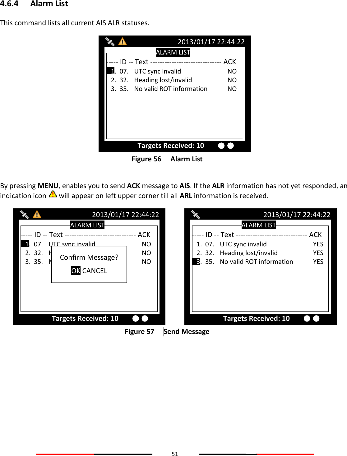
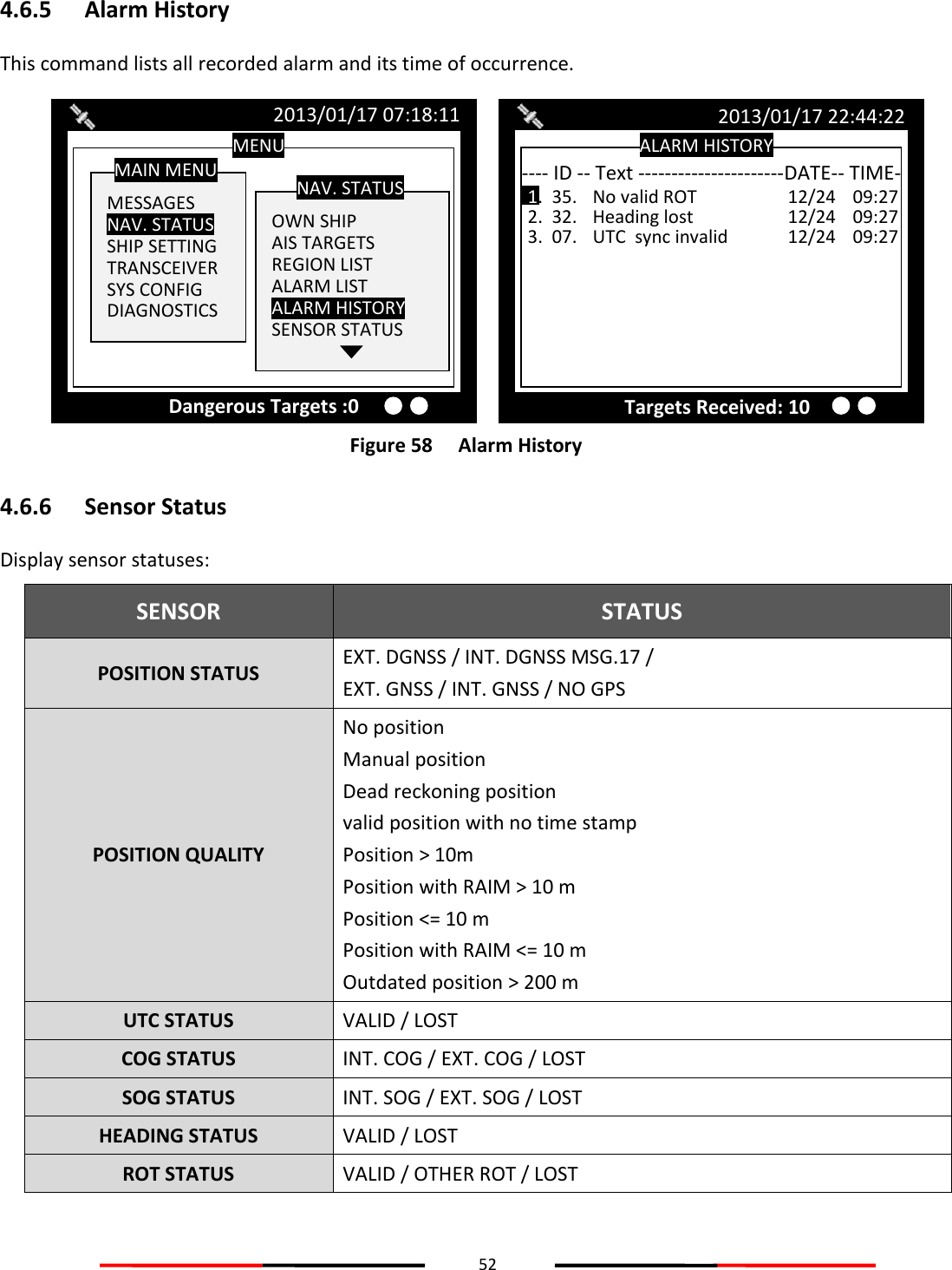
![53 The channel status below records TXT message received times. AIS: Channel management parameters changed. Figure 59 Sensor Status 4.6.7 Dangerous List Any vessel with less than the safe encountering time (TCPA) and distance (CPA) will be listed in DANGEROUS LIST for navigation purposes and safety references. Figure 60 Dangerous List DANGEROUS TARGETS 2013/01/17 22:44:22 [003]-- NAME ------ MMSI -- CPA ----- TCPA - 1. TEST01 210000000 3.84 35.98 TX POWER LEVEL: 12.5W SENSOR STATUS 2013/01/17 22:43:39 TX POWER LEVEL: 12.5W POSITION STATUS EXT. GNSS UTC STATUS LOST COG STATUS EXT. COG SOG STATUS EXT. SOG HEADING STATUS VALID ROT STATUS VALID --DATE TIME--CHANNEL PARAMETER CHANGE-- POSITION QUALITY Position with RAIM <= 10 m](https://usermanual.wiki/Alltek-Marine-Electronics/AIS-A701/User-Guide-1979443-Page-59.png)
![54 Turn the knob to select a vessel and press to read its information. Figure 61 Ship Detail (1) Press the knob again to go the second page for more detail. Figure 62 Ship Detail (2) SHIP DETAIL <2/2> 2013/01/17 22:43:39 CALL TEST MMSI 210000000 CARGO Unknown Cargo! TYPE Vessel-Pleasure craft NAME TEST01 DEST TPI ETA 02/28 01:30 BEAM 0m Pos. Quality Position with RAIM <= 10 m 006/023 DRAUGHT N/A IMO 000000000 DTE N/A [CLASS A] A:0m B:0m C: 0m D:0m A B C D LENGTH 0m TX POWER LEVEL: 12.5W SHIP DETAIL <1/2> 2013/01/17 22:43:39 TX POWER LEVEL: 12.5W NAME TEST01 CALL TEST MMSI 210000000 [CLASS A] NAV. AIS-SART LON 121°45’00”E LAT 025°09’25”N SOG 3.00Kn COG 000.0° ROT 0.0° 001/001 EPFS GPS RNG 5.43NM BRG 270° CPA 3.84 NM HDG 125.0° TCPA 54.31 min P.A Hi Manoeuvre Ind. not available RAIM In use](https://usermanual.wiki/Alltek-Marine-Electronics/AIS-A701/User-Guide-1979443-Page-60.png)
![55 4.6.8 MOB List This command enables adding, removing, or modifying of MOB list entries. Button Action MENU Add, Remove entry Knob Button Modify a selected entry Figure 63 MOB List (1) After pressing the Menu button, a prompt appears. Figure 64 MOB List (2) Select ADD NEW to enter edit mode. MOB LIST 2013/01/17 17:04:39 TX POWER LEVEL: 12.5W [000]-- ID ------ NAME -------------------------- DELETE ADD NEW MOB LIST 2013/01/17 17:04:38 TX POWER LEVEL: 12.5W [000]-- ID ------ NAME --------------------------](https://usermanual.wiki/Alltek-Marine-Electronics/AIS-A701/User-Guide-1979443-Page-61.png)
![56 Figure 65 MOB List (3) When finished entering MMSI and the assigned name, press MENU or ESC to save or leave without saving. Figure 66 MOB List (4) After finished adding, the list now has the new MMSI. To modify an entry, only need to press the knob to enter edit mode. Figure 67 MOB List (5) MOB LIST 2013/01/17 17:04:42 TX POWER LEVEL: 12.5W [000]-- ID ------ NAME -------------------------- 1. 970000001 TEST EDIT MOB YES NO MOB LIST 2013/01/17 17:04:41 TX POWER LEVEL: 12.5W MMSI [970000001] NAME [TEST ] Save Data? YES NO MOB LIST 2013/01/17 17:04:40 TX POWER LEVEL: 12.5W MMSI [970000001] NAME [TEST ]](https://usermanual.wiki/Alltek-Marine-Electronics/AIS-A701/User-Guide-1979443-Page-62.png)
![58 4.7 Ship Setting This sub-menu lists all the ship information settings of your ship. There are a total of 4 setting commands. Figure 70 Ship Setting 4.7.1 Own Ship To access OWN SHIP setting, you are required to enter your password (The default password is 0000). Choose a text location, and then press the knob to enter text input mode. Turn the knob to select a character, and then press the knob to confirm and to return. Repeat these steps till all desired characters are entered. After entering the password, press down the knob for 3 seconds to confirm. Figure 71 Own Ship MENU MESSAGES NAV. STATUS SHIP SETTING TRANSCEIVER SYS CONFIG DIAGNOSTICS MAIN MENU OWN SHIP VOYAGE CPA/TCPA CHANGE MMSI/IMO RETRY TIMES SHIP SETTING 2013/01/17 07:18:11 Dangerous Targets :0 Please enter the password and hold KNOB for confirmation. [ **** ] PASSWORD MENU MESSAGES NAV. STATUS SHIP SETTING TRANSCEIVER SYS CONFIG DIAGNOSTICS MAIN MENU OWN SHIP VOYAGE CPA/TCPA CHANGE MMSI/IMO RETRY TIMES SHIP SETTING 2013/01/17 07:18:11 Dangerous Targets :0](https://usermanual.wiki/Alltek-Marine-Electronics/AIS-A701/User-Guide-1979443-Page-64.png)
![59 If the password is correct, the system will proceed to the settings page, else a system message will indicate that the password is wrong. Figure 72 Own Ship Setting Pressing MENU or ESC button will ask whether to save data. Turn knob to choose and press knob to confirm your choice. 4.7.2 Voyage VOYAGE provides navigation functionalities, such as navigation destination, time of arrival, navigation status, etc. Figure 73 Voyage Setting Pressing MENU or ESC button will ask whether to save data. Select YES to save and exit, or NO to exit without saving. VOYAGE SETTING 2013/01/17 22:43:39 Targets Received: 10 ETA [00/00 00:00] CARGO <N/A or Harmless> NAV. <Under way using engine> PERSON [0000] DRAUGHT(m) [+00.0] DESTIN [ ] Save data? YES NO VOYAGE SETTING 2013/01/17 22:43:39 Targets Received: 10 ETA [00/00 00:00] CARGO <N/A or Harmless> NAV. <Under way using engine> PERSON [0000] DRAUGHT(m) [+00.0] DESTIN [ ] SHIP SETTING 2013/01/17 22:43:39 Dangerous Targets :10 SHIP NAME [AMEC ] SHIP TYPE <Pilot vessel> INTERNAL ANT. POS. (m) EXTERNAL ANT. POS. (m) A B C D A [000] B [000] C [00] D[00] A [000] B [000] C [00] D[00] CALL SIGN [0001 ] Save data? YES NO SHIP SETTING 2013/01/17 22:43:39 SHIP NAME [AMEC ] SHIP TYPE <Pilot vessel> INTERNAL ANT. POS. (m) EXTERNAL ANT. POS. (m) A B C D A [000] B [000] C [00] D[00] A [000] B [000] C [00] D[00] CALL SIGN [0001 ] Dangerous Targets :10](https://usermanual.wiki/Alltek-Marine-Electronics/AIS-A701/User-Guide-1979443-Page-65.png)
![60 4.7.3 CPA/TCPA This command holds the settings to configure dangerous ship criteria (TCPA and CPA) and the alarm. Figure 74 CPA/TCPA Pressing MENU or ESC button will ask whether to save data. Select YES to save and exit, or NO to exit without saving. 4.7.4 Change MMSI/IMO Before entering Change MMSI/IMO page, please enter the password (Default password: “0000”). Press and hold the knob for 3 seconds as confirmation. Figure 75 Change MMSI/IMO (1) This command provides settings to enter MMSI and IMO. Turn knob to traverse the items and press to enter the setting screen. MENU MESSAGES NAV. STATUS SHIP SETTING TRANSCEIVER SYS CONFIG DIAGNOSTICS MAIN MENU OWN SHIP VOYAGE CPA/TCPA Change MMSI/IMO RETRY TIMES SHIP SETTING 2013/01/17 07:18:11 Dangerous Targets :0 Please enter the password and hold KNOB for confirmation. [ **** ] PASSWORD CPA/TCPA 2013/01/17 22:43:39 Targets Received: 10 TCPA (min) [90] ALARM <OFF> CPA (NM) [95] Save data? YES NO CPA/TCPA 2013/01/17 22:43:39 Targets Received: 10 TCPA (min) [90] ALARM <OFF> CPA (NM) [95]](https://usermanual.wiki/Alltek-Marine-Electronics/AIS-A701/User-Guide-1979443-Page-66.png)
![61 Figure 76 Change MMSI/IMO (2) Turn the knob to change the position and press knob to enter text input mode. Turn the knob to change value and press knob again to confirm. Repeat these procedures till all values are entered. Double check to ensure value is entered correctly and press MENU or ESC to save. Figure 77 MMSI/IMO Setting (3) The system will ask for your confirmation. IMO SETTING 2013/01/17 07:18:11 IMO [000000000] Targets Received: 10 MMSI SETTING 2013/01/17 22:43:39 Targets Received: 10 MMSI [000000000] MMSI RANGE: 20000000~799999999 or 982000000~987000000 Change MMSI/IMO 2013/01/17 22:43:39 Targets Received: 10 IMO [000000000] MMSI [000000000]](https://usermanual.wiki/Alltek-Marine-Electronics/AIS-A701/User-Guide-1979443-Page-67.png)
![62 Figure 78 Save Data 4.7.5 Retry Times In order to resend messages when the transmitted Message 6 or Message 12 receives no response of Message 7 or Message 13, set the Retry Times to set the resending times. Figure 79 Retry Times Set Retry Times 2013/01/17 22:43:39 Targets Received: 10 Retry Times <3> IMO SETTING 2013/01/17 07:18:11 IMO [000000000] Targets Received: 10 Save data? YES NO MMSI SETTING 2013/01/17 22:43:39 Targets Received: 10 MMSI [000000000] MMSI RANGE: 20000000~799999999 or 982000000~987000000 Save data? YES NO](https://usermanual.wiki/Alltek-Marine-Electronics/AIS-A701/User-Guide-1979443-Page-68.png)
![63 4.8 Transceiver TRANSCEIVER setting sub-menu holds the settings of the transceiver statuses and the supplied voltage for the GPS antenna. Figure 80 Transceiver Pressing MENU or ESC button will ask whether to save data. Select YES to save and exit, or NO to exit without saving. Added AIS TX POWER option to configure transmit power, provided with 12.5W and 1W transmit options. 4.9 Sys Config System configuration provides the preference settings of the device. Figure 81 System configuration MENU MESSAGES NAV. STATUS SHIP SETTING TRANSCEIVER SYS CONFIG DIAGNOSTICS MAIN MENU SENSOR CONFIG. FACTORY PASSWORD LONG RANGE SET. LR BCST SET. DEST. TABLE SET. SYS CONFIG 2013/01/17 07:18:11 Dangerous Targets :0 MENU MESSAGES NAV. STATUS SHIP SETTING TRANSCEIVER SYS CONFIG DIAGNOSTICS MAIN MENU CUSTOMIZE RADAR VIEW MAP CALIBRATION SENSOR CONFIG. FACTORY PASSWORD SYS CONFIG 2013/01/17 07:18:11 Dangerous Targets :0 TRANSCEIVER SETTING 2013/01/17 22:43:39 Targets Received: 10 DSC Rx <ON> AIS Tx <ON> GPS ANT. VOLTAGE <3.3V> MENU MESSAGES NAV. STATUS SHIP SETTING TRANSCEIVER SYS CONFIG DIAGNOSTICS MAIN MENU 2013/01/17 07:18:11 Dangerous Targets :0 Please enter the password and hold KNOB for confirmation. [ **** ] PASSWORD](https://usermanual.wiki/Alltek-Marine-Electronics/AIS-A701/User-Guide-1979443-Page-69.png)
![64 4.9.1 Customize Customize provides personalization settings. Figure 82 Customize Pressing MENU or ESC button will ask whether to save data. Select YES to save and exit, or NO to exit without saving. 4.9.2 Radar View This setting provides user the ability to center the radar map on given coordinates. Turn knob to choose either latitude or longitude and press knob to confirm. Once pressed, turn knob to choose a parameter and press knob again to enter input mode. When finished, press ESC to return to the level before. Continue these procedures till all settings are set. Figure 83 Radar View Setting Pressing MENU or ESC button will ask whether to save data. Select YES to save and exit, or NO to exit without saving. Added with RADAR VIEW ORIENTATION mode, with NORTH UP/ COURSE UP / HEAD UP. RADAR VIEW SETTING 2013/01/17 22:43:39 Targets Received: 10 Latitude [53]°[08]’[56]”<N> Center position of radar view Longitude [057]°[00]’[00]”<W> RADAR VIEW ORIENTATION MODE <NORTH UP> CUSTOMIZE 2013/01/17 22:43:39 Targets Received: 10 COLOR MODE [Day] KEY TIME-OUT [1] (1~5 min) LANGUAGE <English> ALARM <OFF> KEY BEEP <None> DIMMER LEVEL [100] Lo………………………Hi TIME ZONE <GMT> SART TEST MODE <OFF>](https://usermanual.wiki/Alltek-Marine-Electronics/AIS-A701/User-Guide-1979443-Page-70.png)
![65 4.9.3 Map Calibration This setting offers user functions to calibrate map data. Turn knob to select either latitude or longitude to offset. Press knob to enter input mode. Turn knob to select an offset value. Once finished press ESC to return to the previous level to continue the setting. Figure 84 Map Calibration Pressing MENU or ESC button will ask whether to save data. Select YES to save and exit, or NO to exit without saving. 4.9.4 Sensor Config Sensor Configuration provides user to set port baud rates. Turn knob to select a port to modify and press knob to change the specified port baud rate. Turn knob to change the desired rate. When finished, press knob again to return to the previous level. Figure 85 Baud Rate Setting Pressing MENU or ESC button will ask whether to save data. Select YES to save and exit, or NO to exit without saving. BAUD RATE SETTING 2013/01/17 22:43:39 DISP <38400> LR <38400> DGPS <38400> SEN 1 <38400> SEN 2 <38400> PILOT <38400> SEN 3 <38400> MENU MESSAGES NAV. STATUS SHIP SETTING TRANSCEIVER SYS CONFIG DIAGNOSTICS MAIN MENU CUSTOMIZE RADAR VIEW MAP CALIBRATION SENSOR CONFIG. FACTORY PASSWORD SYS CONFIG 2013/01/17 07:18:11 Please enter the password and hold KNOB for confirmation. [ **** ] PASSWORD Dangerous Targets :0 MAP CALIBRATION 2013/01/17 22:43:39 Targets Received: 3 LON OFFSET [+0.000000] LAT OFFSET [+0.000000] TX POWER LEVEL: 12.5W](https://usermanual.wiki/Alltek-Marine-Electronics/AIS-A701/User-Guide-1979443-Page-71.png)
![66 4.9.5 Factory FACTORY option enables user restore default factory setting. It restores system preference settings and CPA/TCPA values. Choose a password text location, and then press the knob to enter text input mode. Turn the knob to select a character, and then press the knob to confirm and to return. Repeat these steps till all desired characters are entered. After entering the password, press down the knob for 3 seconds to confirm. Figure 86 Factory After entering the password, the system will ask for your confirmation. Turn knob to choose and press knob to confirm your choice. Figure 87 Factory Setting MENU MESSAGES NAV. STATUS SHIP SETTING TRANSCEIVER SYS CONFIG DIAGNOSTICS MAIN MENU 2013/01/17 07:18:11 Dangerous Targets :0 Restore Factory Setting? OK CANCEL WARNING MENU MESSAGES NAV. STATUS SHIP SETTING TRANSCEIVER SYS CONFIG DIAGNOSTICS MAIN MENU CUSTOMIZE RADAR VIEW MAP CALIBRATION SENSOR CONFIG. FACTORY PASSWORD SYS CONFIG 2013/01/17 07:18:11 Dangerous Targets :0 Please enter the password and hold KNOB for confirmation. [ **** ] PASSWORD](https://usermanual.wiki/Alltek-Marine-Electronics/AIS-A701/User-Guide-1979443-Page-72.png)
![67 4.9.6 Password This option enables changing user password. (Default password: “0000”) Set the information with the order of “OLD PASSWORD”, “NEW PASSWORD”, “CONFIRM NEW PASSWORD”. Turn knob to traverse the items and press knob to enter input mode. Under input mode, turn knob to select text position and press knob to confirm. Repeat till all four values are entered. Figure 88 Password Pressing MENU or ESC button will ask whether to save data. Select YES to save and exit, or NO to exit without saving. 4.9.6.1 Changing the Password The password is required in some menu items due to information security. (Default password: “0000”) Please go to Main MENU item Sys Config and select sub-menu item Password to change it. For password setting, please refer to 4.5.6 PASSWORD. Figure 89 Changing Password PASSWORD SETTING 2013/01/17 07:18:11 Dangerous Targets : 0 NEW Password [ **** ] Confirm Password [ **** ] OLD Password [ **** ] MENU MESSAGES NAV. STATUS SHIP SETTING TRANSCEIVER SYS CONFIG DIAGNOSTICS MAIN MENU CUSTOMIZE RADAR VIEW MAP CALIBRATION SENSOR CONFIG FACTORY PASSWORD SYS CONFIG 2013/01/17 07:18:11 Dangerous Targets :0 PASSWORD SETTING 2013/01/17 07:18:11 Dangerous Targets : 0 NEW Password [ **** ] Confirm Password [ **** ] OLD Password [ **** ]](https://usermanual.wiki/Alltek-Marine-Electronics/AIS-A701/User-Guide-1979443-Page-73.png)
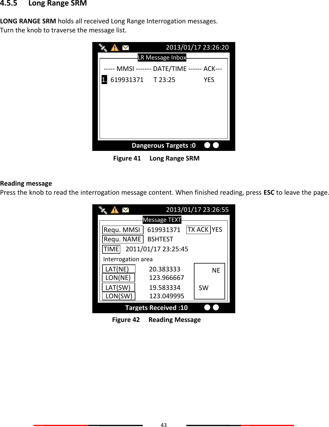
![68 4.9.7 Long Range Setting This option provides user choices to auto-response remote interrogation and settings of the response information. You can either set MODE to either AUTO or MANUAL. The setting for the rest of information is either SUPPLY or REJECT. Figure 90 Long Range Setting Pressing MENU or ESC button will ask whether to save data. Select YES to save and exit, or NO to exit without saving. 4.9.8 Long Range Broadcast Class A transmits Message 27 every 3 minutes through the channels alternately. Provided here are the options to enable or disable Long Range Broadcast and the transmitting channel for Message 27. Figure 91 Long Range Broadcast Only AIS channel numbers can be entered for TX channel. Channel 2078, 2088, and the current channel used in the region cannot be used. LONG RANGE BROADCAST SETTING 2013/01/17 22:43:39 TX POWER LEVEL: 12.5W TX Channel 1 [0075] TX Channel 2 [0076] LONG RANGE BROADCASTFS<ENABLE> MENU MESSAGES NAV. STATUS SHIP SETTING TRANSCEIVER SYS CONFIG DIAGNOSTICS MAIN MENU SENSOR CONFIG. FACTORY PASSWORD LONG RANGE SET. LR BCST SET. DEST. TABLE SET. SYS CONFIG 2013/01/17 07:18:11 Dangerous Targets :0 LONG RANGE INTERROGATION SETTING 2013/01/17 22:43:39 Targets Received: 10 Name, Call,IMO <SUPPLY> Length, Breadth, Type <SUPPLY> Date, Time <SUPPLY> Ship/Cargo <SUPPLY> Dest. ETA <SUPPLY> Draught <SUPPLY> COG <SUPPLY> POS <SUPPLY> SOG <SUPPLY> POB <SUPPLY> MODE <AUTO>](https://usermanual.wiki/Alltek-Marine-Electronics/AIS-A701/User-Guide-1979443-Page-74.png)
![69 4.9.9 Destination Table Setting Save up to 10 destinations. Use rotary knob to traverse text and to modify. Press Menu to save changes. Figure 92 Destination Table Setting DESTINATION TABLE SETTING 2013/01/17 22:43:39 Dangerous Targets: 0 Column 2 [ ] Column 3 [ ] Column 4 [ ] Column 5 [ ] Column 6 [ ] Column 1 [ ] Column 7 [ ] Column 8 [ ] Column 9 [ ] Column 10 [ ]](https://usermanual.wiki/Alltek-Marine-Electronics/AIS-A701/User-Guide-1979443-Page-75.png)
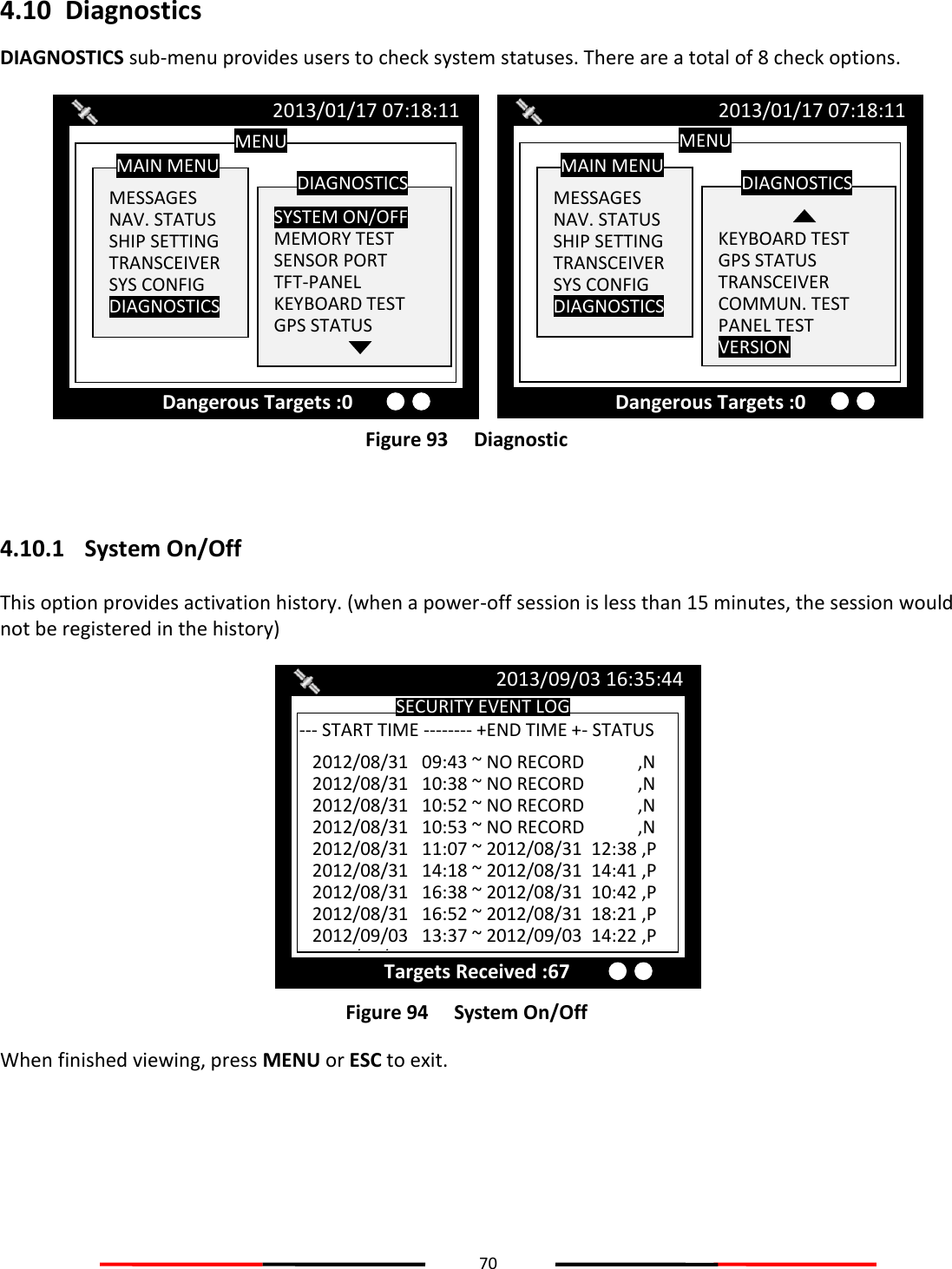
![71 4.10.2 Memory Test This option provides memory testing on the unit. Figure 95 Memory Test When finished, press ESC to exit. 4.10.3 Sensor Port This option provides an overview on all port baud rates and information. Figure 96 Sensor Port When finished, press ESC to exit. SENSOR PORT 2013/01/17 22:43:39 Targets Received: 3 DISP <38400> V V LR <38400> V V DGPS <38400> V V SEN 1 <38400> V -- SEN 2 <38400> V -- PILOT <38400> V V SEN 3 <38400> V -- Baud Rate RX TX MEMORY TEST 2013/01/17 22:43:39 Targets Received: 10 Chart Memory [Pass] System Memory [Pass] Data Memory](https://usermanual.wiki/Alltek-Marine-Electronics/AIS-A701/User-Guide-1979443-Page-77.png)