Alltek Marine Electronics AIS-A701 AIS Class A Transponder User Manual Users manual
Alltek Marine Electronics Corporation AIS Class A Transponder Users manual
Users manual
1
I
General Information
i. Copyright
The entire contents of this instruction manual, including any future updates, revisions, and
modifications, shall remain the property of AMEC at all times. Unauthorized copies or reproduction of
this manual, either in part or whole, in any form of print and electronic media, is prohibited. The
contents herein can only be used for the intended purpose of this manual.
ii. Disclaimer
AMEC is devoted to publish and maintain this product manual. As we continue to improve our AIS
products to satisfy all customers’ needs, information in this document is subject to change without
notice. AMEC does not make any representations or warranties (implied or otherwise) regarding the
accuracy and completeness of this document and shall in no event be liable for any loss of profit or any
commercial damage, including but not limited to special, incidental, consequential, or other damage.
iii. Safety Warning
It is important to know that AIS is designed for the purpose of anti-collision and serves as a
complement to navigation. It is not the absolute navigational equipment and does not replace
any navigational system installed on board.
Any AIS device cannot guarantee monitoring and receiving signals from all vessels in the
surroundings unless those vessels are equipped with AIS devices.
The coastline map in this transponder is neither verified nor approved by Hydrographic
Authorities. It is not an Electronic Chart System and therefore should not be used for
navigation. The information provided by the coastline map is for reference only and should be
used together with other navigation sources and devices.
ELECTRICAL SHOCK HAZARD
Improper disassemble or modification could cause electrical shocks, fire, or personal injury.
Only qualified personnel could work on the interior of the equipment.
MAKE SURE THE POWER SOURCE AND THE POWER INPUT ARE MATCH
Incorrect power sources will damage the equipment and may even result in fire.
Please ensure the correct power input on the adaptor before installation.
AVOID DIRECT CONTACT WITH RAIN OR SPLASHING WATER
Electrical shock or fire could be resulted if water leaks into the equipment.
NOTE/INFORMATION
Important notices and information will be noted in this Installation and Operation Manual

II
iv. Product Category
This product is categorized as “protected” in accordance with the requirements as defined in IEC 60945.
v. Compass Safe Distance
Safe distance to the transponder (and junction box) unit is:
Standard-magnetic-compass: 0.50 m
Steering-magnetic-compass: 0.40 m
vi. Hardware / Software Version
Hardware version: A701-010
Software version: 1.0.6.23
The model name/number, hardware information, and firmware (software) version of the transponder
can be identified through MKD at MENU/DIAGNOSTICS/VERSION. The software maintenance/upgrade
of the transponder can be carried out on board via USB interface. The onboard documentation as
described in Appendix C can be used to assist reflecting software maintenance records.
vii. Manual Revision
Version 1.10
viii. Type Approval
The AMEC CAMINO-701 AIS transponder complies with applicable international standards and is type
approved in accordance with the European Marine Equipment Directive.
ix. Declaration of Conformity
Hereby, Alltek Marine Electronics Corp. (AMEC) declares that this CAMINO-701 is in compliance with
the essential requirements and other relevant provisions of Directive 96/98/EC.
x. Disposal Instruction
Do not dispose of this device with unsorted waste.
Improper disposal may be harmful to the environment and human health. Please refer to your local
waste authority for information on return and collection systems in your area.
xi. Contact Information
For sales, services, and technical supports, please contact your local AMEC representatives or Alltek
Marine Electronics Corp at www.alltekmarine.com or sales@alltekmarine.com or
service@alltekmarine.com

i
Table of Contents
1 WHAT IS AIS? .................................................................................................................. 1
2 SYSTEM OVERVIEW ......................................................................................................... 2
2.1 PRODUCT DESCRIPTION ....................................................................................................................... 2
2.2 MAIN FEATURES ............................................................................................................................... 2
2.3 INTERCONNECTION DIAGRAM ............................................................................................................... 3
3 INSTALLATION ................................................................................................................. 4
3.1 EQUIPMENTS IN THE BOX ..................................................................................................................... 4
3.2 INSTALLATION PROCEDURES ................................................................................................................. 4
3.3 RF CABLE REQUIREMENTS ................................................................................................................... 5
3.4 VHF ANTENNA INSTALLATION .............................................................................................................. 5
3.5 GPS ANTENNA INSTALLATION ............................................................................................................... 6
3.6 MOUNTING CAMINO-701 ................................................................................................................. 7
3.6.1 Mounting Transponder ....................................................................................................................... 7
3.6.2 Mounting Junction Box ....................................................................................................................... 9
3.6.3 Mounting Pilot Plug .......................................................................................................................... 10
3.7 EXTERNAL CONNECTORS (TRANSPONDER MAIN UNIT) .............................................................................. 12
3.8 EXTERNAL CONNECTORS (JUNCTION BOX) .............................................................................................. 13
3.9 CONNECTING EXTENSION CABLE .......................................................................................................... 16
3.10 CONFIGURING CAMINO-701 ............................................................................................................ 17
3.10.1 Initial Configuration ...................................................................................................................... 17
4 OPERATION ................................................................................................................... 19
4.1 PANEL DESCRIPTION ......................................................................................................................... 19
4.1.1 Status Bar .......................................................................................................................................... 20
4.1.2 Transmission and Reception Bar ...................................................................................................... 21
4.2 DISPLAY MODES ............................................................................................................................. 22
4.2.1 Target Symbol Descriptions .............................................................................................................. 23
4.2.2 Coastal View ...................................................................................................................................... 25
4.2.3 Radar View ........................................................................................................................................ 26
4.2.4 Dangerous Target List ....................................................................................................................... 26
4.2.5 Own Ship Detail ................................................................................................................................. 26
4.2.6 GPS Satellite Information .................................................................................................................. 26
4.2.7 Dimmer Setting ................................................................................................................................. 27
4.3 ENTERING TEXT ............................................................................................................................... 28
4.4 MENU TREE OVERVIEW .................................................................................................................... 30
4.4.1 How to access and use MAIN MENU ................................................................................................ 31
4.4.2 Menu Item Brief Description ............................................................................................................ 32
4.5 MESSAGES ..................................................................................................................................... 34
4.5.1 Inbox SRM ......................................................................................................................................... 34
4.5.2 Outbox SRM ...................................................................................................................................... 36
4.5.3 Broadcast SRM .................................................................................................................................. 37
4.5.4 Addressed SRM ................................................................................................................................. 41
4.5.5 Long Range SRM ............................................................................................................................... 43

ii
4.6 NAVIGATION STATUS ........................................................................................................................ 45
4.6.1 Own Ship ........................................................................................................................................... 45
4.6.2 AIS Targets ........................................................................................................................................ 46
4.6.3 Region List ......................................................................................................................................... 49
4.6.4 Alarm List .......................................................................................................................................... 51
4.6.5 Alarm History .................................................................................................................................... 52
4.6.6 Sensor Status..................................................................................................................................... 52
4.6.7 Dangerous List ................................................................................................................................... 53
4.6.8 MOB List ............................................................................................................................................ 55
4.6.9 Friend Ships ....................................................................................................................................... 57
4.7 SHIP SETTING ................................................................................................................................. 58
4.7.1 Own Ship ........................................................................................................................................... 58
4.7.2 Voyage ............................................................................................................................................... 59
4.7.3 CPA/TCPA .......................................................................................................................................... 60
4.7.4 Change MMSI/IMO ........................................................................................................................... 60
4.7.5 Retry Times ....................................................................................................................................... 62
4.8 TRANSCEIVER ................................................................................................................................. 63
4.9 SYS CONFIG ................................................................................................................................... 63
4.9.1 Customize .......................................................................................................................................... 64
4.9.2 Radar View ........................................................................................................................................ 64
4.9.3 Map Calibration ................................................................................................................................ 65
4.9.4 Sensor Config .................................................................................................................................... 65
4.9.5 Factory .............................................................................................................................................. 66
4.9.6 Password ........................................................................................................................................... 67
4.9.7 Long Range Setting ........................................................................................................................... 68
4.9.8 Long Range Broadcast ....................................................................................................................... 68
4.9.9 Destination Table Setting .................................................................................................................. 69
4.10 DIAGNOSTICS ................................................................................................................................. 70
4.10.1 System On/Off .............................................................................................................................. 70
4.10.2 Memory Test ................................................................................................................................. 71
4.10.3 Sensor Port .................................................................................................................................... 71
4.10.4 TFT-Panel ....................................................................................................................................... 72
4.10.5 Keyboard Test ............................................................................................................................... 72
4.10.6 GPS Status ..................................................................................................................................... 73
4.10.7 Transceiver .................................................................................................................................... 73
4.10.8 Communication Test ..................................................................................................................... 74
4.10.9 Panel Test ...................................................................................................................................... 76
4.10.10 Version .......................................................................................................................................... 76
5 TECHNICAL SPECIFICATIONS .......................................................................................... 77
5.1 APPLICABLE STANDARDS ................................................................................................................... 77
5.2 VHF TRANSCEIVER ........................................................................................................................... 77
5.3 DSC RECEIVER ................................................................................................................................ 77
5.4 GPS RECEIVER (INTERNAL) ................................................................................................................ 78
5.5 POWER SUPPLY ............................................................................................................................... 78
5.6 LCD DISPLAY ................................................................................................................................. 78
5.7 KEYPAD & KNOB ............................................................................................................................. 78

iii
5.8 CONNECTION INTERFACE ................................................................................................................... 78
5.9 ENVIRONMENTAL ............................................................................................................................ 79
5.10 PHYSICAL....................................................................................................................................... 79
5.11 PILOT PLUG.................................................................................................................................... 79
6 MECHANICAL DIMENSIONS ........................................................................................... 80
6.1 CAMINO-701 TRANSPONDER MAIN UNIT ........................................................................................... 80
6.2 JUNCTION BOX ............................................................................................................................... 82
6.3 EXTENSION CABLE ............................................................................................................................ 82
6.4 MOUNTING TEMPLATE (NOT TO SCALE) ................................................................................................. 82
6.5 VHF ANTENNA ............................................................................................................................... 83
6.6 GPS ANTENNA ............................................................................................................................... 83
6.7 PILOT PLUG.................................................................................................................................... 83
7 TROUBLESHOOTING ...................................................................................................... 84
8 ABBREVIATIONS ............................................................................................................ 85
Multi-functional Satellite Augmentation System ......................................................................................... 86
APPENDIX (A) ...................................................................................................................... 87
APPENDIX (B) .....................................................................................................................103
APPENDIX (C) ......................................................................................................................104

1
1 WHAT IS AIS?
The Automatic Identification System (AIS) is a Very High Frequency (VHF) radio broadcasting system that
transfers packets of data over the VHF data link (VDL) and enables AIS equipped vessels and shore-based
stations to exchange identification information and navigational data. Ships with AIS transponders continually
transmit their ID, position, course, speed and other data to all nearby ships and shore stations. Such
information can aid greatly in situational awareness and provide a means to assist in collision avoidance.
AIS equipment is standardized by ITU, IEC, IALA and IMO and is subject to approval by a certification body. The
following AIS devices have been developed for variant applications.
AIS Class A:
mandated by the IMO for vessels of 300 gross tonnages and upwards engaged on international voyages,
cargo ships of 500 gross tonnages and upwards, as well as passenger ships. It transmits typically on 12.5
watt output power.
AIS Class B:
provides limited functionality and is intended for non-SOLAS commercial vessels and recreational vessels.
It transmits typically on 2 watt output power.
AIS Base Station:
is provided by aids-to-navigation authorities to enable the ship to shore / shore to ship transmission of
information. Networked AIS Base Stations can assist in providing overall maritime domain awareness.
AIS AtoN (Aids to Navigation):
provides an opportunity to transmit position and status of buoys and lights through the same VDL, which
can then show up on AIS-ready devices within the range.
AIS SART:
Search and Rescue Transmitter using AIS can be used to assist in determining the location of a vessel in
distress. It is typically used on life rafts.
AIS on Search and Rescue (SAR) Aircraft:
used on airplanes and helicopters to assist search and rescue operation.
2
2 SYSTEM OVERVIEW
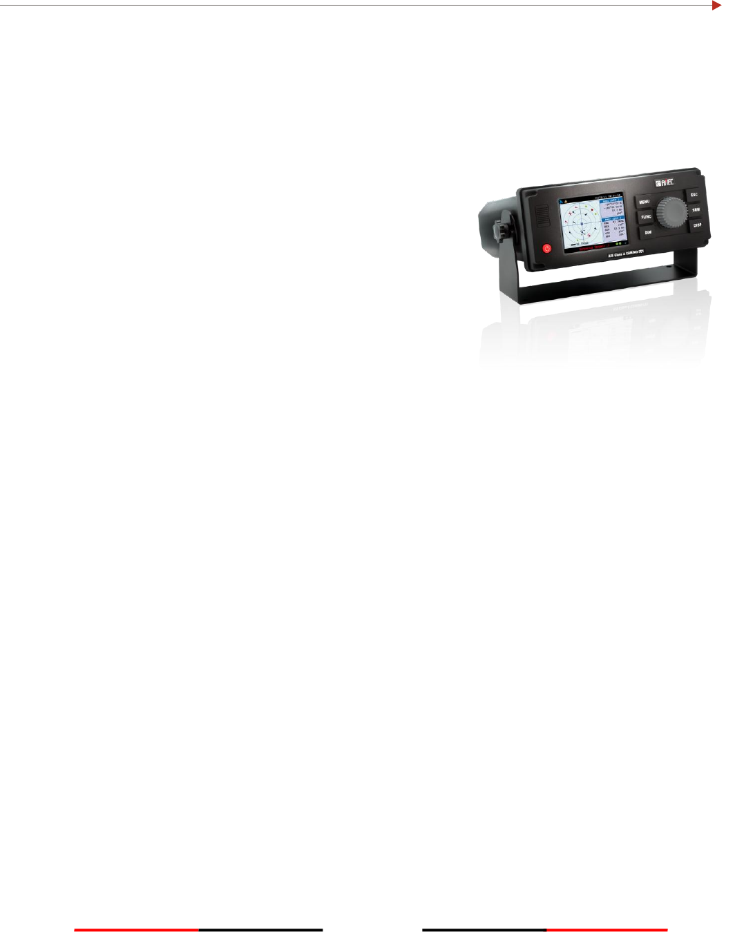
2.1 Product Description
The AMEC CAMINO-701 is a new generation AIS Class A transponder fully compliance with IMO, IEC, and ITU
international standards. It provides a compact single box solution, easy to install and operate. The unit is
designed with advanced technology which sets a new standard for quality, performance, and value. It is an
excellent choice for SOLAS vessels, commercial vessels, and
professional vessels.
The CAMINO-701 consists of a transceiver radio unit, an
integrated GPS receiver, a controller unit, and a color 3.5” LCD
display with menu keypads. The radio has three receivers -- two
TDMA receivers and one DSC receiver. The transmitter alternates
its transmission between the two operating TDMA. The controller
unit creates and schedules data packets (containing dynamic,
static and voyage related data) for transmission based on the IMO
performance standard for AIS.
The CAMINO-701 can be connected to the ship’s sensors as
required by the IALA guidelines through an external junction box
(supplied in the package). The unit can also interface external navigation and presentation systems that
support IEC 61162-1 related sentences. It is also capable for connection to Long Range system like Inmarsat C.
The CAMINO-701 supports both IMO and Inland AIS which is configurable by the software.
The color LCD display and menu keypads provide an intuitive graphical user-friendly interface to the system. It
can display the location of other vessels, aids to navigation and search and rescue vessels. The AIS transmit
and receive status are shown on the screen which helps user to know the working status of the unit easily. The
LCD and keypad can also be used to send and receive messages, perform configuration as well as supervise the
systems status.
2.2 Main Features
Compact AIS Class A solution, easy to install and operate
Fully compliant with IMO, IEC, and ITU international standards
Color 3.5” LCD display with variant display modes
User-friendly intuitive GUI & keypad operation
Knob dial, click and push, for simple operation
IMO/Inland AIS mode selectable (optional)
Multiple sensor input ports and bi-directional data ports
USB (device only) and NMEA2000 connectivity ready
3
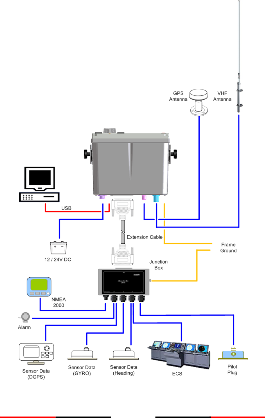
2.3 Interconnection Diagram
Figure 1 Interconnection Diagram
4
3 INSTALLATION
3.1 Equipments in the Box
The standard supply in the package includes the following items. Please contact your local representative if
any item is missing.
Description
Quantity
CAMINO-701 Class A AIS Transponder
1
Junction box
1
U-shaped mounting bracket
1
Knobs for u-shaped mounting brackets
2
37-pin extension cable 1.8 m Connector: CDS-37P
1
3-pin power cable 1m Connector: LTW:BB-03RMMS-LC7001
1
USB to Mini-USB data cable 1.8 m
1
Panel mount stainless bracket and screw
2
M3.5X10 screws for u-shaped mounting bracket
5
M4X6 screws for panel mount brackets
6
Panel mount cutting template
1
Screw, wall-plug, mounting stand for junction box
4
Installation and operation manual
1
Software CD
1
Optional Items
Description
Quantity
GPS antenna with integrated cable 10m
1
GPS antenna mounting bracket kit
1
Pilot plug box with wired cable 2m
1
Screws for pilot plug box
2
3.2 Installation Procedures
Please familiarize the manual content before begin installation. Use the following recommended steps for
installation.
1. Mount the transponder unit to a desired location
2. Mount junction box.
3. Install VHF antenna
4. Install GPS antenna
5. Connect all external sensors and data interfaces to the junction box
6. Connect all required cables to the main transponder unit
7. Power on the main transponder unit
8. Complete configuration settings
9. Perform system functional test
5
3.3 RF Cable Requirements
The following RF cables are recommended to install the CAMINO-701.
VHF Antenna Cable
Type: 5D-FB or equivalent
Connector: SO-239 (Male)
GPS Antenna Cable
Type: RG58A/U or equivalent
Connector: TNC (Male)
3.4 VHF Antenna Installation
The quality and positioning of the antenna are the most important factors dictating AIS performance. It is
recommended that a VHF antenna with omni directional vertical polarization be specifically tuned for AIS
operation band. Since the range of VHF signals is largely decided by line of sight distance, the VHF antenna
should be placed as high as possible and at least 5 meters away from any constructions made of conductive
materials.
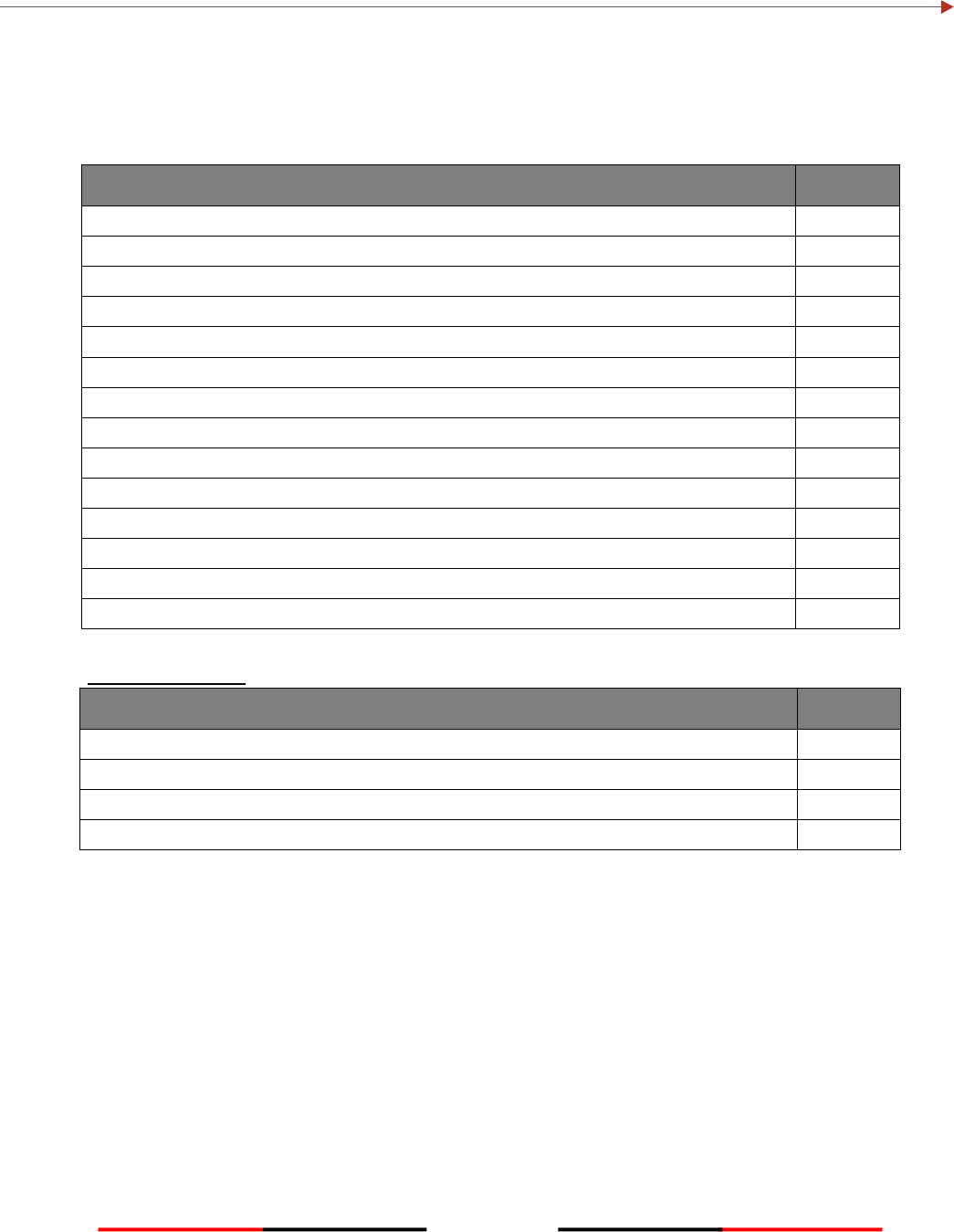
To avoid interference, the VHF antenna location should be placed accordingly as diagram below:
Figure 2 VHF/GPS Antenna Locations
Ensure a free 360˚ horizon with a
vertical observation of 5˚.
5˚
High power transmitting antenna
3m
Ensure the GPS antenna is not on the
transmitting beam with other
high power transmitting antenna.
VHF
Antenna.
Other VHF
Antenna
The recommended
vertical distance
between antennas is
2m.
The recommended
horizontal distance
between antennas
is 10m.
Other transmitting
antenna
10m
The recommended horizontal
distance between GPS antennas and
other antennas is 3m.

6
3.5 GPS Antenna Installation
The GPS antenna must be installed where it has a clear view of the sky, so that it may access the horizon freely
with 360° degrees, with a vertical observation of 5 to 90 degrees above the horizon as illustrated below.
GPS ANTENNA LOCATION
Enter the GPS antenna location data in “SHIP SETTING” after the installation.
Figure 3 GPS Antenna location
B
C
D
A
7
3.6 Mounting CAMINO-701
Use the following guidelines to check the installation location for your AIS transponder:
The AIS transponder should be mounted in a location that is accessible and readable to user
at all time.
The transponder should be installed in a protected environment away from direct rain and
water contact.
The transponder is designed to operate in an environment with 15°C ~ 55°C temperature.
Environments with excessive heat may cause damages to the transponder.
The transponder should not be installed near flammable or hazardous environments.
The AIS transponder should be installed at least 0.5m away from magnetic compasses.
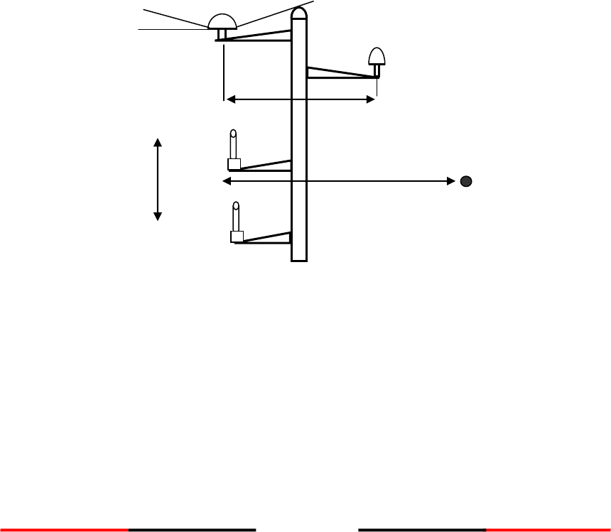
3.6.1 Mounting Transponder
Figure 4 Mounting CAMINO-701
8
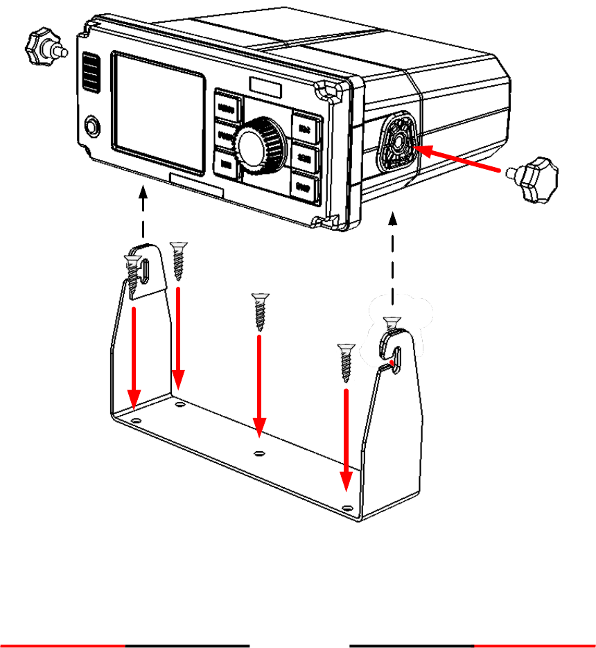
Panel Mounting (1)
1. Line up the mounting template on control panel to sketch an outline for the cutting area.
2. Using a jigsaw carefully cut along the sketched cutting area.
3. If necessary, clean up edge with glass paper or file.
4. Mount the transponder through the opening.
5. From the rear, install the mounting brackets with the M4X6 screws.
6. Apply the mounting bracket screw on each side for a firm fix.
Figure 5 Panel Mounting (1)
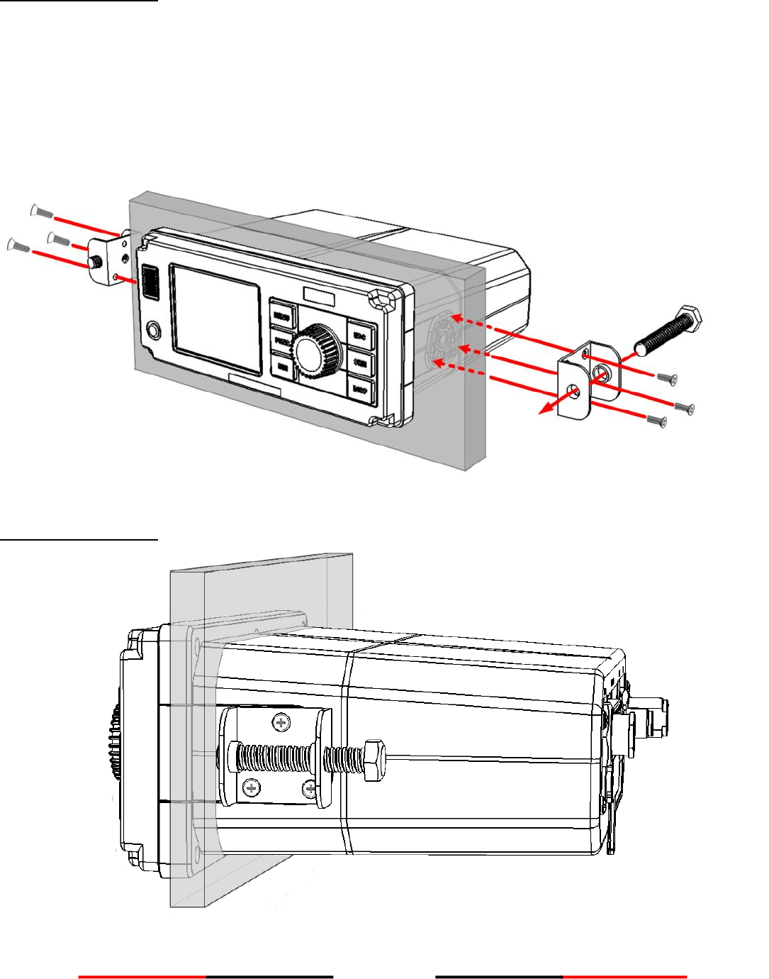
Panel Mounting (2)
Figure 5 Panel Mounting (2)
9
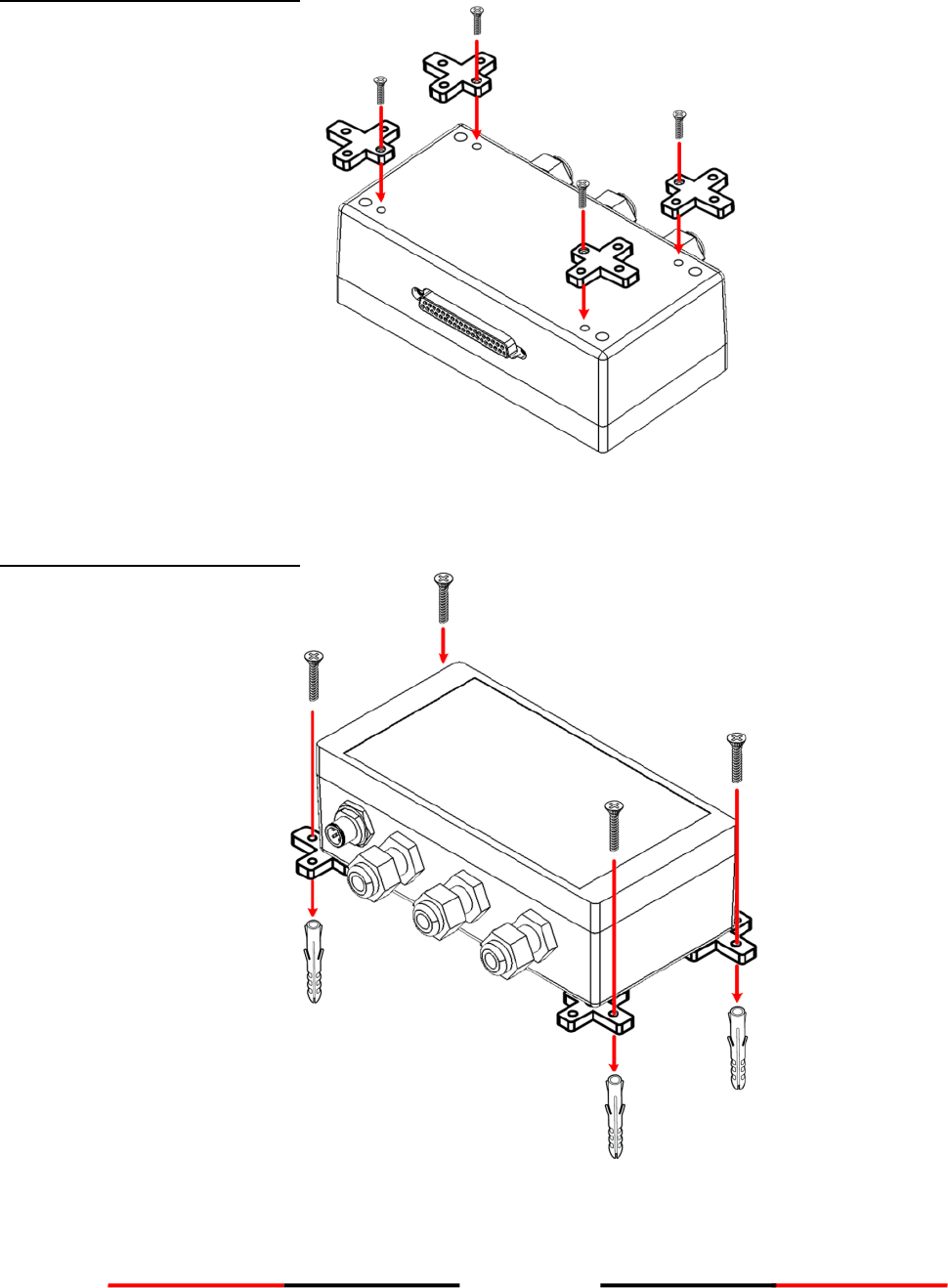
3.6.2 Mounting Junction Box
Mounting Junction Box (1)
Figure 6 Mounting Junction Box (1)
Mounting Junction Box (2)
Figure 7 Mounting Junction Box (2)
10
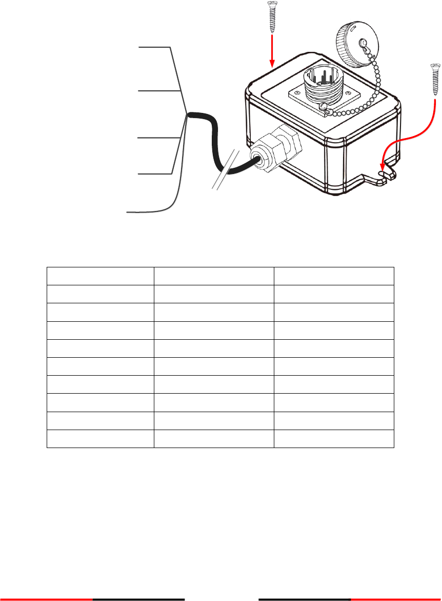
3.6.3 Mounting Pilot Plug
The Pilot Plug device provides connecting interface to pilots and other mariners to connect their own PC or
other portable device to Camino701 on board.
Camino-701 Pilot Plug
Pin Number
Function
Wire Color
Pin 1
Tx A
Red
Pin 2
--
Pin 3
--
Pin 4
Tx B
White
Pin 5
Rx A
Black
Pin 6
Rx B
Green
Pin 7
--
Pin 8
--
Pin 9
Shield (Ground)
Tx A Pin1 (Red)
Tx B Pin 4 (White)
Rx A Pin 5 (Black)
Rx B Pin 6 (Green)
Shield Pin 9
11
Connecting to Camino-701 Junction Box
Use the following guidelines to connect the Pilot Plug to the Camino701 Junction box.
Please refer to section 3.8 External Connectors (Junction Box).
Cable Glands
To Transponder Main Unit
NMEA 2000
Pilot plug
PILOT_IN A connects to Rx A (Black)
PILOT_IN B connects to Rx B (Green)
PILOT_IN GND connects to Shield
PILOT_OUT A connects to Tx A (Red)
PILOT_OUT B connects to Tx B (White)
PILOT_OUT GND connects to Shield
Note: Shield can connect to either
PILOT_IN GND or PILOT_OUT GND.
12
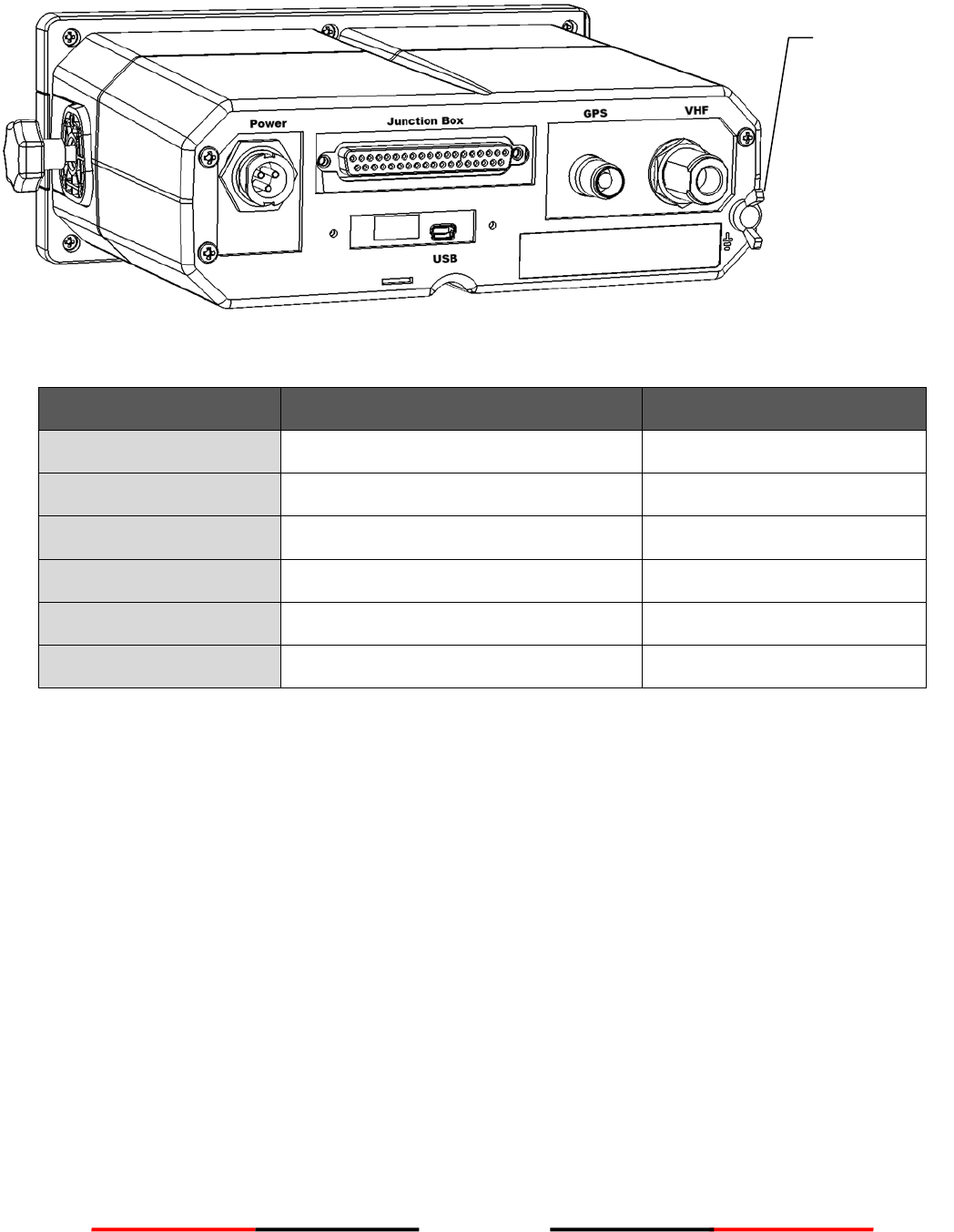
3.7 External Connectors (Transponder Main Unit)
Figure 8 External Connectors (Main Unit)
NAME
DESCRIPTION
TYPE OF CONNECTOR
VHF
VHF antenna connector
SO-239 (female)
GPS
GPS antenna connector
TNC (female)
Power
Power input connector
Round type, 3 pins
USB
USB connection to PC
Mini type USB
Junction Box
Extension connection to Junction Box
D-Sub 37 pins
Frame Ground
Connect to ship frame
Note: Some boats require frame ground connection of all electronic devices on the ship frame.
Frame Ground
13
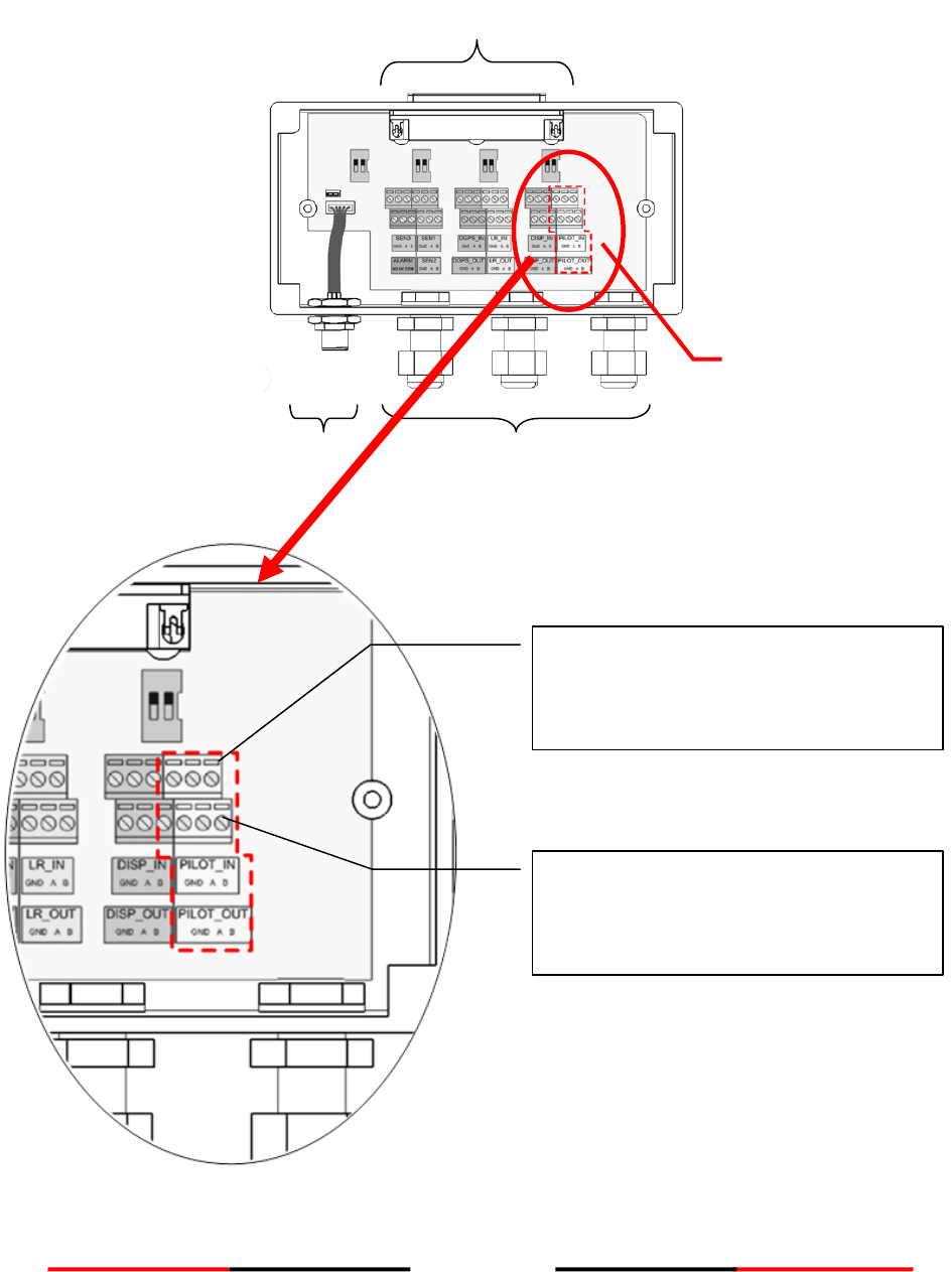
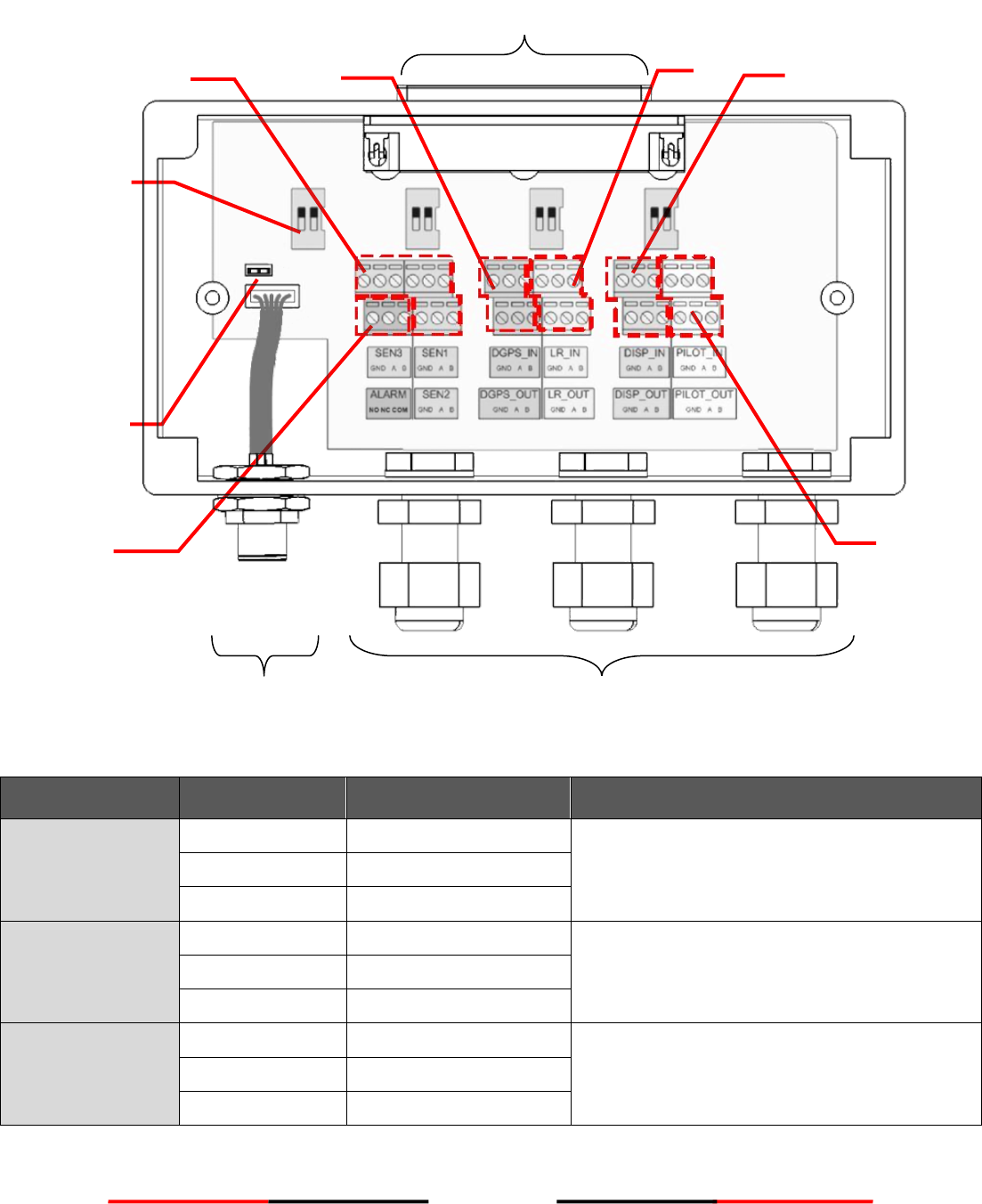
3.8 External Connectors (Junction Box)
Figure 9 External Connectors (Junction Box)
CONNECTOR
LABEL NAME
DESCRIPTION
FUNCTION USAGE
Sensor 1
SEN1_IN GND
Sensor 1 ground
Connect to data sources such as heading,
gyro, or other type of sensors.
SEN1_IN A
Sensor 1 input A
SEN1_IN B
Sensor 1 input B
Sensor 2
SEN2_IN GND
Sensor 2 ground
Connect to data sources such as heading,
gyro, or other type of sensors.
SEN2_IN A
Sensor 2 input A
SEN2_IN B
Sensor 2 input B
Sensor 3
SEN3_IN GND
Sensor 3 ground
Connect to data sources such as heading,
gyro, or other type of sensors.
SEN3_IN A
Sensor 3 input A
SEN3_IN B
Sensor 3 input B
Cable Glands
Sensors 1~3
DGPS
sensor
DISP
Alarm
Pilot plug
LR
Jumper for
NMEA2000
shield and
ground
Termination
switches
To Transponder Main Unit
NMEA 2000

14
Pilot Plug
PILOT_IN GND
Input Ground
Pilot Plug port
PILOT_IN A
Input A
PILOT_IN B
Input B
PILOT_OUT GND
Output Ground
PILOT_OUT A
Output A
PILOT_OUT B
Output B
Alarm
ALARM NO
Alarm normally open
ALARM NC
Alarm normally closed
ALARM COM
Alarm common
DGPS Input
DGPS_IN GND
DGPS input ground
DGPS sensor
DGPS_IN A
DGPS input A
DGPS_IN B
DGPS input B
DGPS Output
DGPS_OUT GND
DGPS output ground
DGPS sensor
DGPS_ OUT A
DGPS output A
DGPS_ OUT B
DGPS output B
LR Input
LR_IN GND
LR input ground
Long range input
LR_IN A
LR input A
LR_IN B
LR input B
LR Output
LR_OUT GND
LR output ground
Long range output
LR_ OUT A
LR output A
LR_ OUT B
LR output B
Display
DISP_IN GND
DISP input ground
Connect to the data output of an external
display system such as ECDIS.
DISP_IN A
DISP input A
DISP_IN B
DISP input B
DISP_OUT GND
DISP output ground
Connect to the data input of an external
display system such as ECDIS.
DISP_OUT A
DISP output A
DISP_OUT B
DISP output B
NOTICE: RTCM-SC-104 beacon input is currently not implemented by the DGPS_IN input.
15
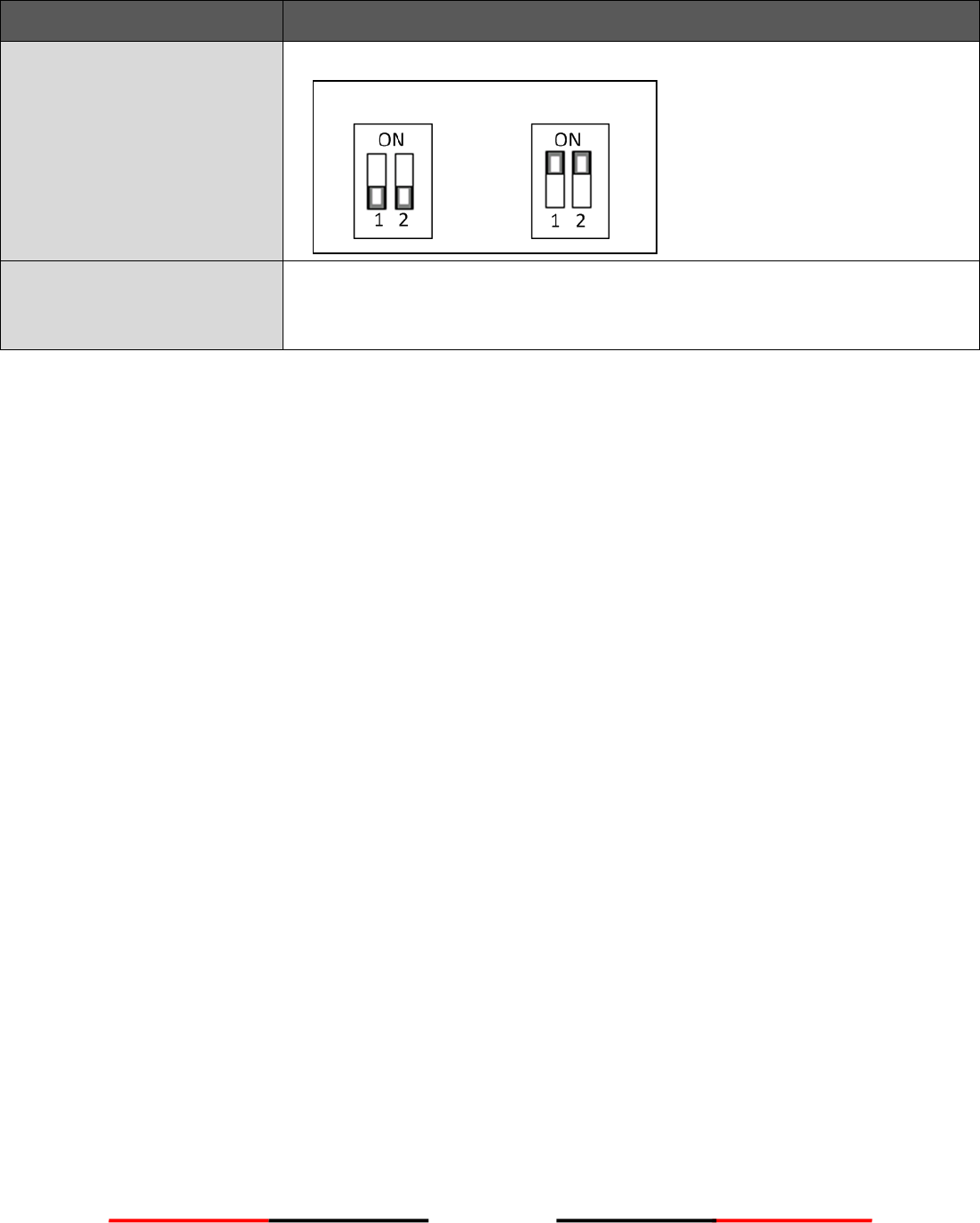
ITEM
USAGE
Termination Switches
The switches provide line termination configuration.
Jumper for NMEA2000
shield and ground
The jumper’s purpose is to wire together NMEA2000 cable’s shield and
ground. Depending on your scenario, you may choose not to connect them
together.
Termination off
Termination on
16
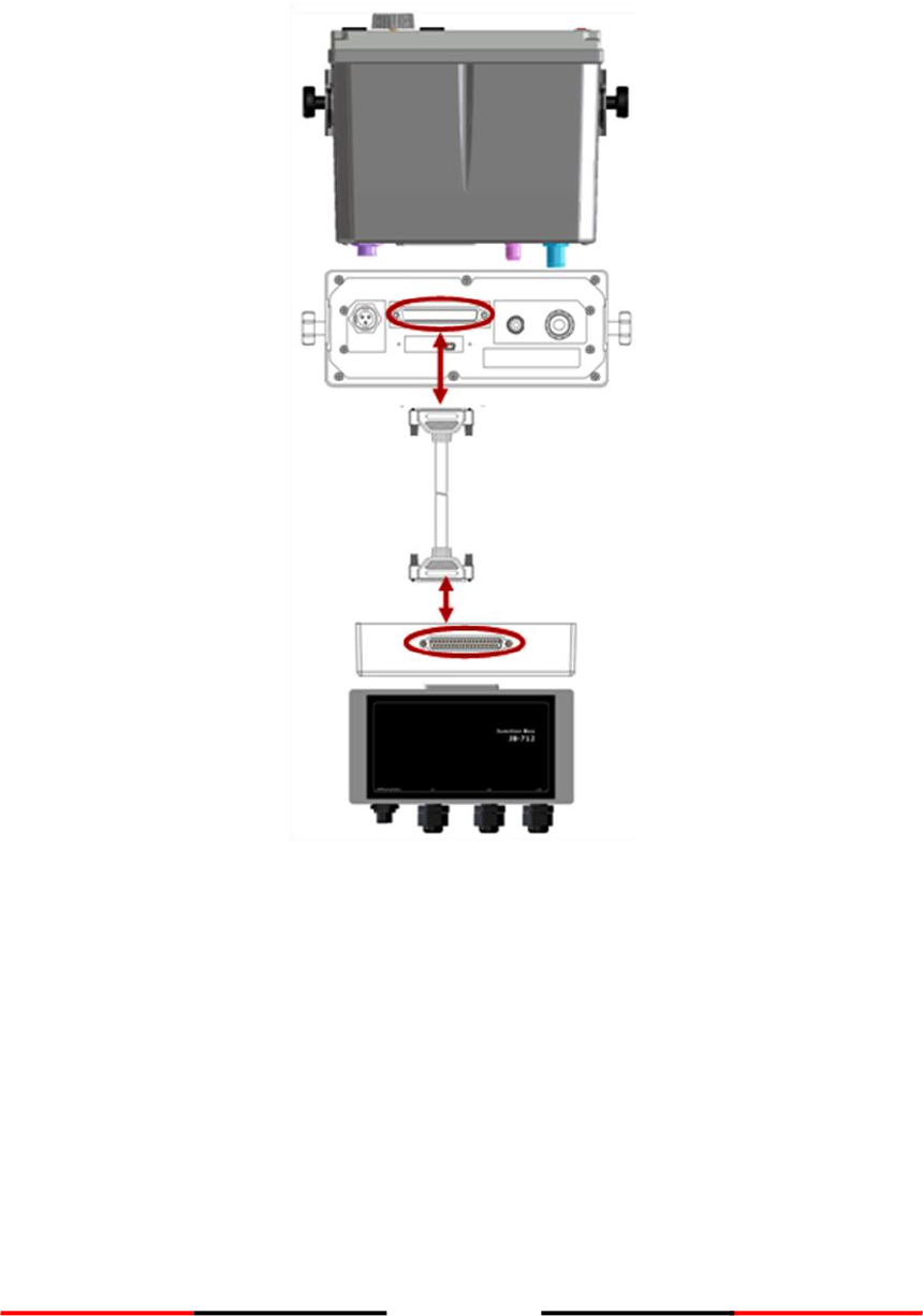
3.9 Connecting Extension Cable
Use the 37-pin- extension cable (1.8M) provided in the package connect CAMINO-701 to the junction box.
Figure 10 Connecting CAMINO-701 with Junction Box
17
3.10 Configuring CAMINO-701
The following items must be completed before initial configuration.
1. Ensure VHF and GPS antennas are well connected to the transponder main unit.
2. Ensure the 37-pin-connector extension cable is well connected from the transponder main unit to the
junction box.
3. Ensure the power cable is well connected and supplied with stable voltage/current power source.
4. Ensure applicable external devices are well connected through the junction box.
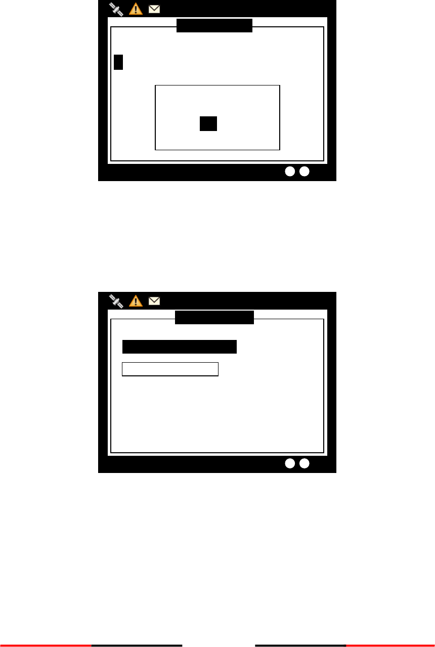
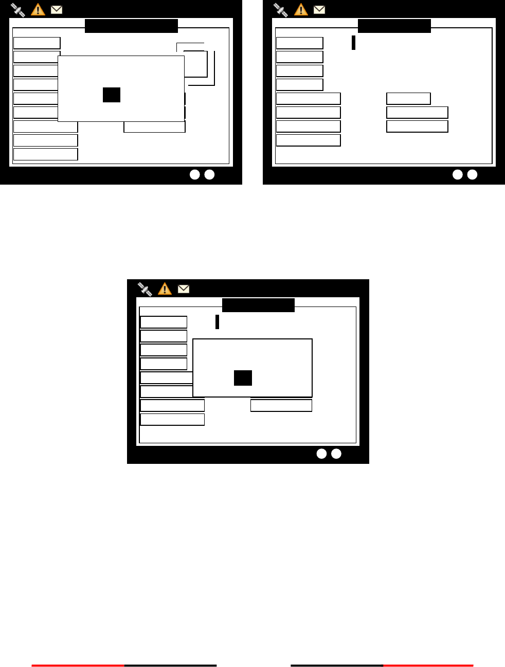
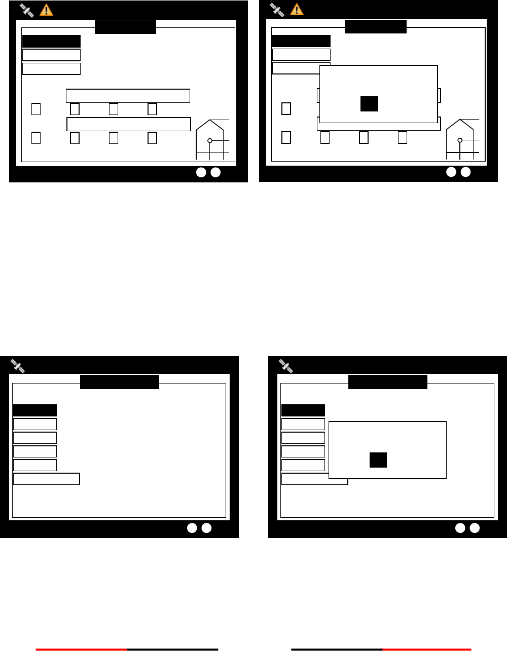
3.10.1 Initial Configuration
The initial configuration, particular, MMSI (Maritime Mobile Service Identity) number must be done before
operation. The following initial configuration is required:
1. Setup 1: MMSI should be correctly programmed.
Figure 11 Built-in Test
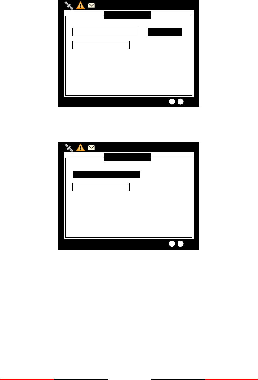
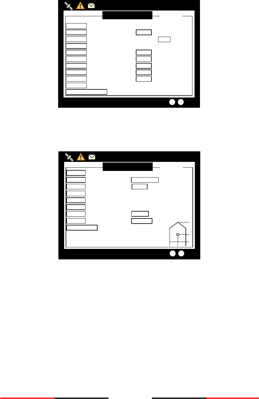
2. Step 2: Press MENU and select main menu item SHIP SETTING. (Password required, default is
“0000”)
Power…………………..…….…………[PASS]
Flash..…………………..…….…………[PASS]
Built-in Test
Transmission inhibited!
Only Receiving Function available!
Set MMSI right now?
YES NO
MMSI unregistered
18
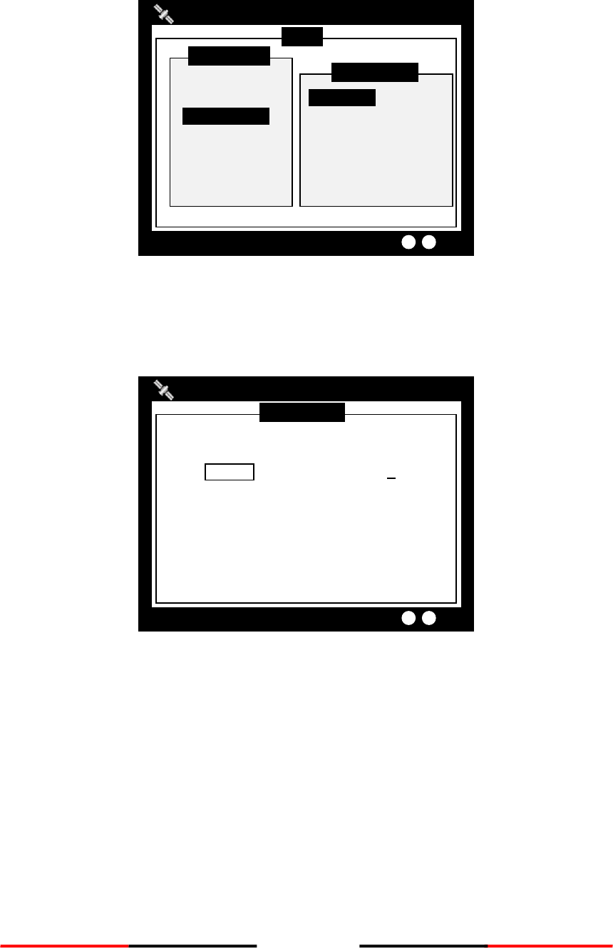
A. Setup call sign, ship name, ship type, external/internal GPS antenna position in OWN SHIP.
Figure 12 Own Ship
B. If IMO identification number is applicable, select main menu item Change MMSI/IMO to setup IMO
number.
Figure 13 IMO Setting
For more information please refer to 4.7 SHIP SETTING.
IMO SETTING
2013/01/17 07:18:11
IMO [000000000]
Targets Received: 10
MENU
MESSAGES
NAV. STATUS
SHIP SETTING
TRANSCEIVER
SYS CONFIG
DIAGNOSTICS
MAIN MENU
OWN SHIP
VOYAGE
CPA/TCPA
CHANGE MMSI/IMO
RETRY TIMES
SHIP SETTING
2013/01/17 07:18:11
Dangerous Targets :0
19
4 OPERATION
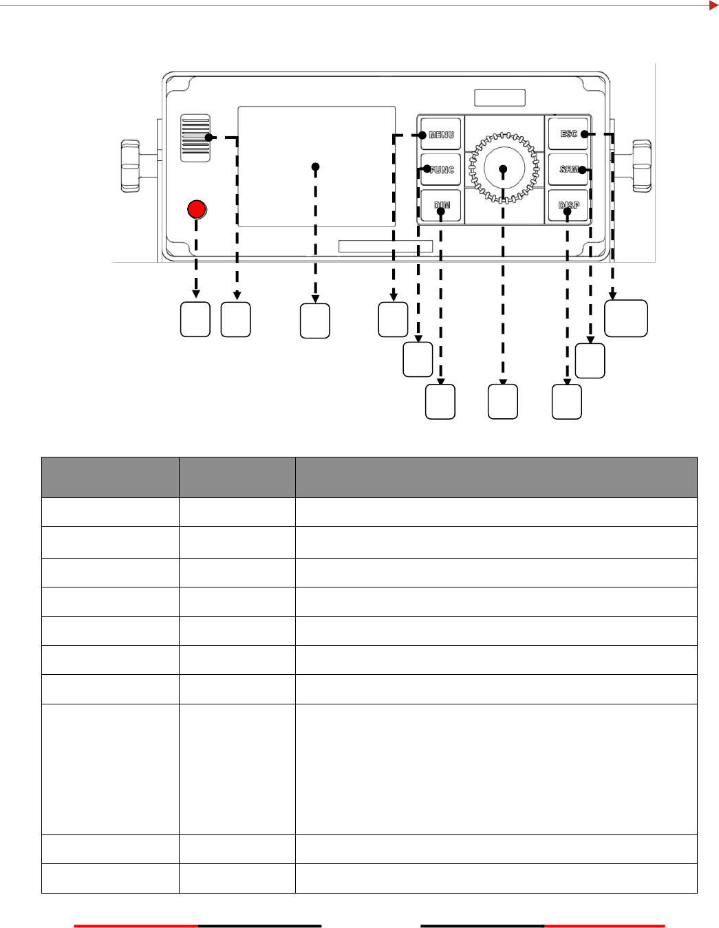
4.1 Panel Description
Figure 14 Panel Description
Item Number
Name
Descriptions
1
Power Switch
Power On/Off (push button over 5 seconds)
2
Beeper
Sound for when buttons are pushed
3
Display
3.5” LCD color screen
4
MENU
Return to main menu / detail menu select
5
FUNC
Different function on display mode (Zoom In/Out, etc)
6
DIM
Adjust dim degree (refer to 4.2.7)
7
Knob
Rotate to select, press to confirm
8
DISP
Change to different display mode:
1 Coastal View
2 Radar View
3. AIS Target List
4. Dangerous Target list
5. Own Ship Detail
6. GPS satellite information
7. Region Setting List
9
SRM
Emergency SRM broadcast
10
ESC
Cancel / Back to Main MENU
1
4
3
2
5
6
8
9
10
7
20
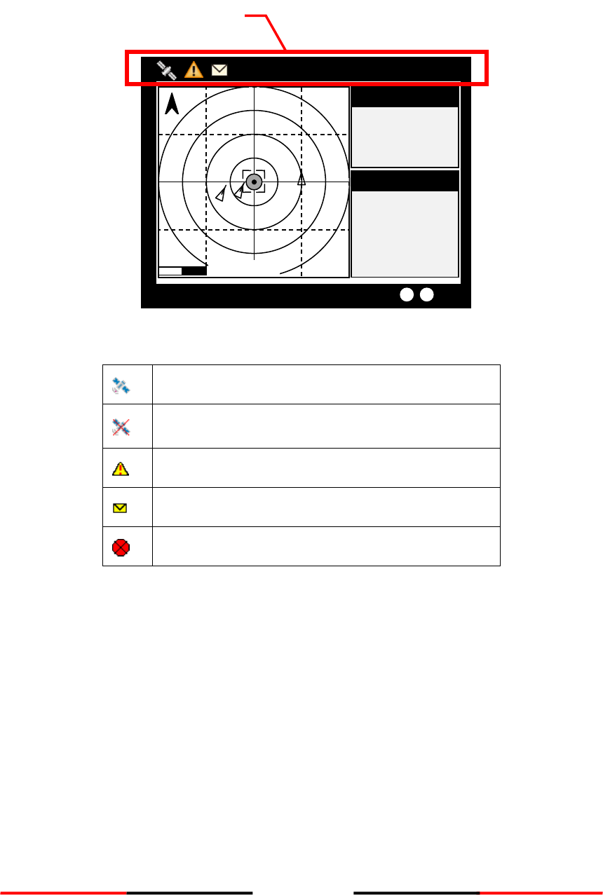
4.1.1 Status Bar
The status bar constantly indicates Date (YYYY/MM/DD), Time, GPS status, ALR, and SRM.
Figure 15 Status Bar
GPS Status:Position fixed
GPS Status:Non-fixed
ALR Status:Alarm messages occurs
Inbox SRM:Unread coming SRM message
SART/MOB:SART or MOB message received
1°13’02”N
103°48’32”E
12.00Kn
360.0°
2013/01/01 07:18:11
Targets Received: 3
AMEC: 15
RNG
BRG
SOG
COG
HDG
AMEC: 15
N
12.000NM
Own Ship
Own Ship
12.00Kn
N/A
0.0°
Status Bar
21
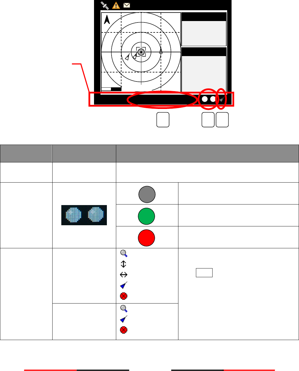
4.1.2 Transmission and Reception Bar
The Transmission & Reception bar constantly displays real time status of transmissions and receptions on any
display modes.
Figure 16 Transmission and Reception Bar
Item Number
Name
Function
1
Text Banner
Shows the numbers of “Targets Received” and “Dangerous
Targets” automatically.
2
Indicators
Ch.87 Ch.88
No transmissions & receptions:
No flash
Reception of AIS message:
Flash green color
Transmission of AIS message:
Flash red color
3
Function Icon
(Coastal view only)
Zoom In/Out
Up/Down
Left/Right
Target Selected
SART/MOB
The function icon indicates the knob’s
action differently in operations.
Push FUNC enables the knob to operate
different actions
Function Icon
(Radar view only)
Zoom In/Out
Target Selected
SART/MOB
1°13’02”N
103°48’32”E
12.00Kn
360.0°
2013/01/01 07:18:11
Targets Received: 3
AMEC: 15
RNG
BRG
SOG
COG
HDG
AMEC: 15
N
12.000NM
Own Ship
Own Ship
12.00Kn
N/A
0.0°
1
2
3
Transmission &
Reception Bar
22
4.2 Display Modes
For quick access, users can rotate display modes by simply pressing the DISP button.
Display Mode
Screen Shot
Purpose
Coastal View
Display all targets on basic coastline map
Radar View
Displays all targets on radar view
AIS Target List
Shows all received ship data
(Refer to section 4.6.2 AIS Targets)
Dangerous Target
List
Shows all dangerous AIS targets presently
(Refer to section 4.6.7 Dangerous List)
Own Ship Detail
Shows all the details of own ship
(Refer to section 4.2.5 Own Ship Detail)
23
GPS Satellite
Information
Shows the GPS satellite current usage status
(Refer to section 4.2.5 GPS Satellite Information)
Region Setting List
Show all the Region of own ship
(Refer to section 4.6.3 Own Ship Detail)
4.2.1 Target Symbol Descriptions
Symbols for each AIS target displayed on the radar view is as described below:
Own Ship
GPS Reception: Normal / Color: Black and Gray
Under normal GPS reception, own ship is located in the center of the radar view.
Own Ship
GPS Reception: No GPS / Color: Blue
Without GPS reception, own ship needs to be located manually.
AIS Target
Color: Black
Ship equipped with AIS system in the surrounding sea will appear on the radar
view as an AIS target.
Selected Target
Color: Black / Flashing Colored Frame
Use the arrow keys to select any target on the radar view. After selected, press
<ENT> and the detailed information on each target can be viewed.
Dangerous Target
Color: Red / Circled Frame
When distance to a ship is smaller than CPA/TCPA, the target will be circled in
RED. Use the arrow keys to select the dangerous target and to view its detailed
information.
Friend Ship
Color: Magenta
If any pre-stored Friend Ship is nearby, the Friend Ship will appear in Magenta on
the radar view.
24
Lost Signal Target
Color: Black / Red Cross
If reception of an AIS target has ceased over 10 minutes, a “X” will be displayed
over it. The target will disappear from the Radar View after its reception has
ceased for one hour.
AtoN (Real)
Color: Black / Plus Sign
The icon will be displayed if any AIS AtoN (Aids to Navigation) Real is in the range
of reception.
AtoN (Virtual)
Color: Black / Plus Sign and Undercut
The icon will be displayed if any AIS AtoN (Aids to Navigation) Virtual is in the
range of reception.
AtoN(Off position)
Color: Red / Plus Sign
The icon will be displayed if any AIS AtoN (Aids to Navigation) is in off position
status.
SAR
Color: Black
The icon will be displayed if any air plane is in the range of reception.
SART
Color: Red / Cross
The icon will be displayed if any SART message is sent out.
Base Station
Color: Green
The icon will be displayed when any base station is in the reception range.
25
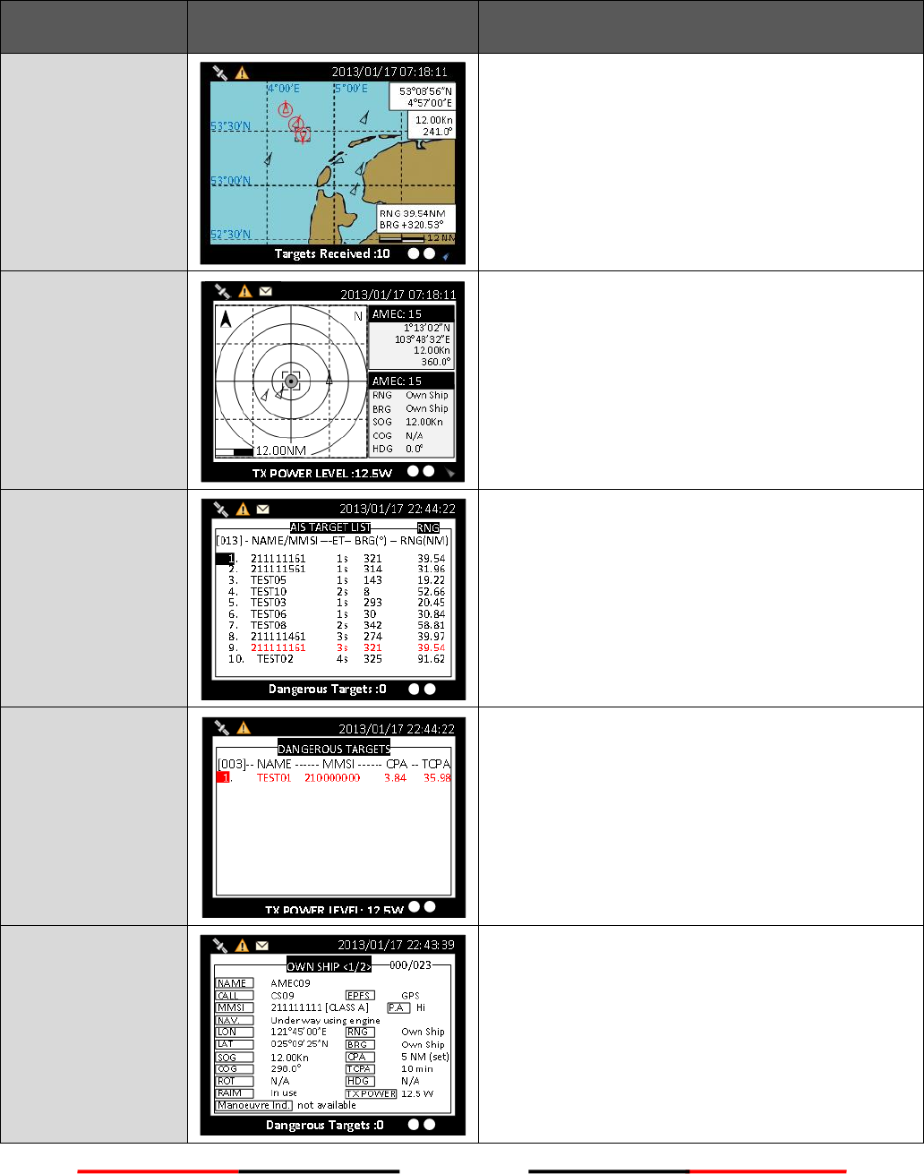
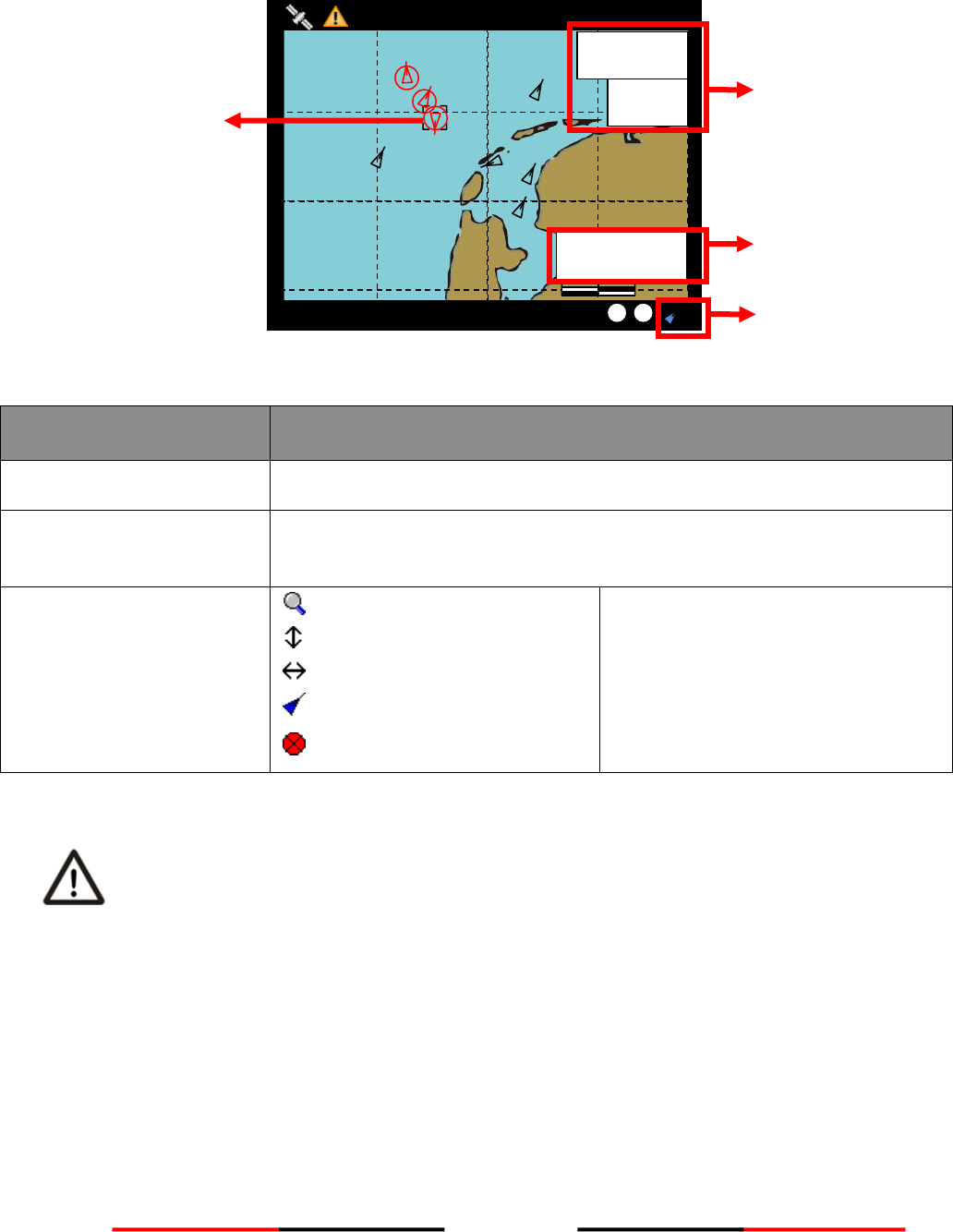
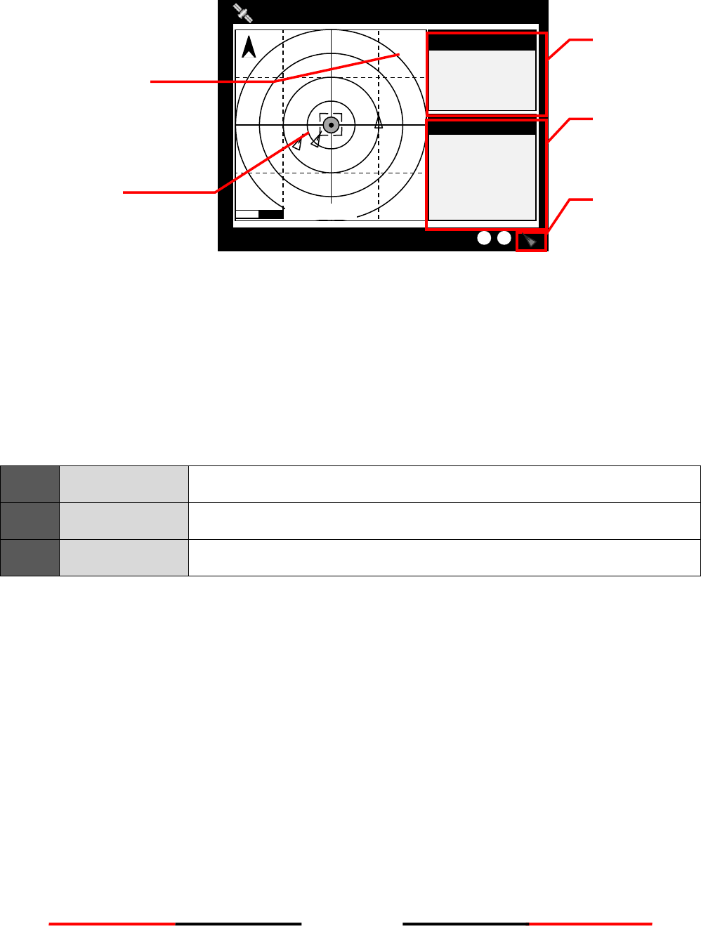
4.2.2 Coastal View
Figure 17 Coastal View
Item
Function
Own Ship information
Own-ship information for latitude, longitude, SOG and COG
Target information
Display the target information such as range and rearing relatively to the
own ship
Function Icon
(Coastal View)
Zoom In/Out
Up/Down
Left/Right
Target Selected
SART/MOB
Function icon
(Coastal View)
The coastline map in this transponder is neither verified nor approved by Hydrographic
Authorities. It is not an Electronic Chart System and therefore should not be used for
navigation. The information provided by the coastline map is for reference only and should be
used together with other navigation sources and devices.
Targets Received :10
12.00Kn
241.0°
53°08’56”N
4°57’00”E
RNG 39.54NM
BRG +320.53°
12 NM
52°30’N
53°00’N
53°30’N
4°00’E
5°00’E
2013/01/17 07:18:11
Own Ship
information
Target
information
Function
Icon
Selected
Target
26
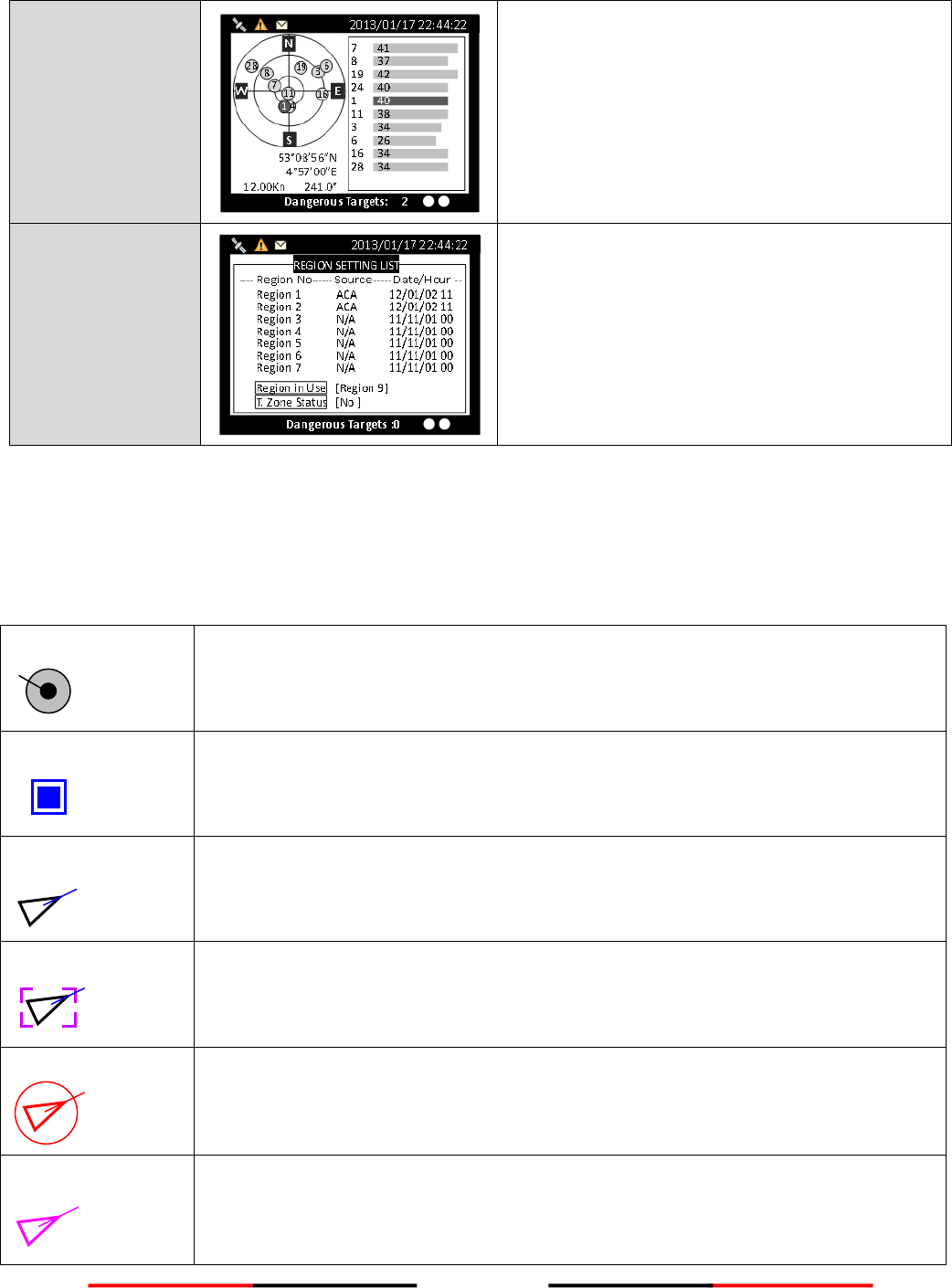
4.2.3 Radar View
Figure 18 Radar View
Radar View displays own ship and target ships’ statuses, and their correlations.
On this view, the vertical grid lines are the longitudinal lines and the horizontal grid lines are the latitudinal
lines. Underneath the radar view is a proportional chart scale showing the current ratio displayed.
Radar View supports three ship orientation modes, North up, Head up, and Course up. Each orientation mode
is indicated by the uppercase letter (N, H, or C) on the right upper corner. The left upper corner is the north
arrow indicating the direction of north.
N
NORTH UP
The chart orientation is fixed and true north is always pointing up.
C
COURSE UP
The orientation is determined by the own ship’s traveling course.
H
HEAD UP
The orientation is determined by the direction of own ship’s bow.
4.2.4 Dangerous Target List
Please refer Section 4.6.7 DANGEROUS LIST
4.2.5 Own Ship Detail
Please refer Section 4.6.1 OWN SHIP
4.2.6 GPS Satellite Information
Please refer Section 4.10.6 GPS STATUS
1°13’02”N
103°48’32”E
12.00Kn
360.0°
2013/01/17 07:18:11
TX POWER LEVEL :12.5W
AMEC: 15
RNG
BRG
SOG
COG
HDG
AMEC: 15
N
12.00NM
Own Ship
Own Ship
12.00Kn
N/A
0.0°
Current mode
Selected target
Own ship
information
Target
information
Function icon
27
4.2.7 Dimmer Setting
Press the button “DIM” to enter the dimmer setting page.
Figure 19 Dimmer Setting
Button
Description
Knob (Turn left/right)
Adjust screen brightness (decrease/increase)
Knob (Press)
Save and leave the page
DIM
Restore screen brightness to default setting (100)
MENU、ESC
Leave the page without saving
CUSTOMIZE
2013/01/17 07:18:11
Dangerous Targets :0
DIMMER LEVEL [ 100 ] Lo Hi
28
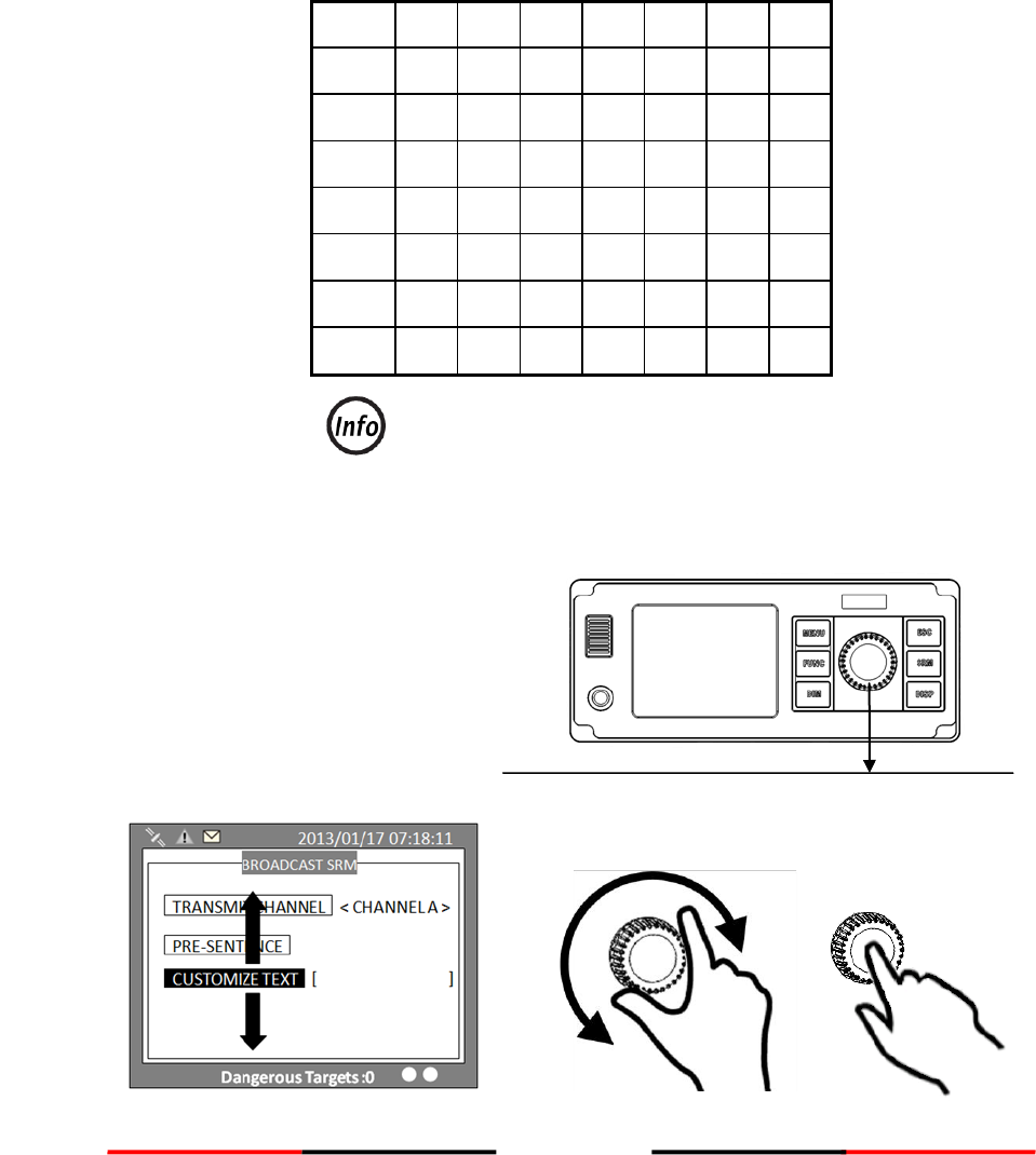
4.3 Entering Text
The knob on the front control panel is used for entering and editing text. The figures below show the text
entering procedures.
A. Turn the knob to traverse the menu items up or down. Once selected, press the knob to select the item
for text entering.
B. Select a character position to edit. Turn the knob to move the cursor left or right and press the knob to
confirm the position.
C. System is now in character selection mode as the cursor position is highlighted. Turn the knob to pick
an available character and press the knob for character selection.
A
B
C
D
E
F
G
H
I
J
K
L
M
N
O
P
Q
R
S
T
U
V
W
X
Y
Z
0
1
2
3
4
5
6
7
8
9
[
\
]
^
_
!
“
#
$
&
‘
(
)
*
+
,
-
.
/
:
;
<
=
>
?
@
Space is first character for selection
D. Use steps B and C to finish entering all needed characters. To confirm and save, press down the knob
and hold for 2 seconds.
A
Turn knob to move
up or down
Press to enter
Traverse menu
29
Figure 20 Entering Text
Press to start
editing
Press knob to
confirm
character selection
To save entered text, long press
the knob for 2 seconds
B
C
D
Turn knob to select
character
Turn knob to move
left or right
Select a character position
Pick character
Confirm and save

30
4.4 Menu Tree Overview
Press MENU button to enter MAIN MENU. There are 6 menu choices and each holds a sub-menu. See table
below.
MESSAGES
NAV. STATUS
SHIP SETTING
TRANSCEIVER
SYS CONFIG
DIAGNOSTICS
1. INBOX SRM (4.5.1)
2. OUTBOX SRM (4.5.2)
3. BROADCASTING SRM (4.5.3)
4. ADDRESSED SRM (4.5.4)
5. LONG RANGE (4.5.5)
1. OWN SHIP (4.6.1)
2. AIS TARGETS (4.6.2)
3. REGION LIST (4.6.3)
4. ALARM LIST (4.6.4)
5. ALARM HISTORY (4.6.5)
6. SENSOR STATUS (4.6.6)
7. DANGEROUS LIST (4.6.7)
8. MOB LIST (4.6.8)
9. FRIEND SHIPS (4.6.8)
1. OWN SHIP (4.7.1)
2. VOYAGE (4.7.2)
3. CPA/TCPA (4.7.3)
4. CHANGE MMSI/IMO (4.7.4)
5. RETRY TIMES (4.7.5)
1. CUSTOMIZE (4.9.1)
2. RADAR VIEW (4.9.2)
3. MAP CALIBRATION (4.9.3)
4. SENSOR CONFIG (4.9.4)
5. FACTORY (4.9.5)
6. PASSWORD (4.9.6)
7. LONG RANGE SET (4.9.7)
8. LONG RANGE BROADCAST (4.9.8)
9. DEST. TABLE SET (4.9.9)
1. SYSTEM ON/OFF (4.10.1)
2. MEMORY TEST (4.10.2)
3. SENSOR PORT (4.10.3)
4. TFT-PANEL (4.10.4)
5. KEYBOARD TEST (4.10.5)
6. GPS STATUS (4.10.6)
7. TRANSCEIVER (4.10.7)
8. COMMUNICATION TEST (4.10.8)
9. PANEL TEST (4.10.9)
10. VERSION (4.10.10)
1. TRANSCEIVER SETTING (4.8)
31
4.4.1 How to access and use MAIN MENU
Figure 21 MAIN MENU
Rotate knob to select MAIN MENU items and push the knob to select sub-menu items.
Figure 22 Sub-menu
MENU
MESSAGES
NAV. STATUS
SHIP SETTING
TRANSCEIVER
SYS CONFIG
DIAGNOSTICS
MAIN MENU
INBOX
OUTBOX
BROADCAST SRM
ADDRESSED SRM
LR INBOX
MESSAGE
2013/01/17 07:18:11
Dangerous Targets :0
Main MENU
Sub- MENU
MENU
MESSAGES
NAV. STATUS
SHIP SETTING
TRANSCEIVER
SYS CONFIG
DIAGNOSTICS
MAIN MENU
2013/01/17 07:18:11
Dangerous Targets :0

32
4.4.2 Menu Item Brief Description
MESSAGES
INBOX
Log of safety related messages (SRM) received
OUTBOX
Log of safety related messages (SRM) sent
BROADCAST SRM
Send SRM.
ADDRESSED SRM
Send specified targeted SRM.
LR INBOX
Log of received inquiry messages from others.
NAVIGATION STATUS (Display a variety of navigation information)
OWN SHIP
Your vessel information
AIS TARGETS
Navigation status and boat information of other
AIS-equipped vessels.
REGION LIST
Regional information status
ALARM LIST
Alarm information
ALARM HISTORY
Alarm history record
SENSOR STATUS
Display sensor statuses
DANGEROUS LIST
Dangerous ship list
MOB LIST
MOB list of registered MOB users
FRIEND SHIPS
Friend ship list
SHIP SETTING (Basic vessel information setting)
OWN SHIP
Your vessel setting (password required, default is 0000)
VOYAGE
Navigation setting
CPA / TCPA
CPA / TCPA
CHANGE MMSI / IMO
Change MMSI / IMO
RETRY TIMES
Times to resend messages.
TRANSCEIVER (Settings for AIS receiving and sending)
AIS TX
Transceiver status: turn on or off AIS message
transmitting
DSC RX
DSC Monitor: turn on or off DSC monitoring function
GPS ANT. VOLTAGE
GPS antenna feeding voltage: set to 3.3V or 5V

33
SYSTEM CONFIGURATION
CUSTOMIZE
Personalization settings
RADAR VIEW
Radar configuration
MAP CALIBRATION
Map offset setting
SENSOR CONFIGURATION
Port configuration
FACTORY
Default factory setting
PASSWORD
Password change (default password: 0000)
LONG RANGE SETTING
Remote inquiry setting
LONG RANGE BROADCAST
Enable/Disable Long Range Broadcast
DESTINATION TABLE SETTTING
Table storing destinations
DIAGNOSTICS
SYSTEM ON/OFF
Device activated log
MEMORY TEST
Memory test
SENSOR PORT
Transmission port test
TFT-PANEL
Screen panel
KEYBOARD TEST
Button test
GPS STATUS
GPS positioning status
TRANSCEIVER
Transponder status
COMMUN. TEST
Test communication
PANEL TEST
Test Panel
VERSION
Firmware version
34
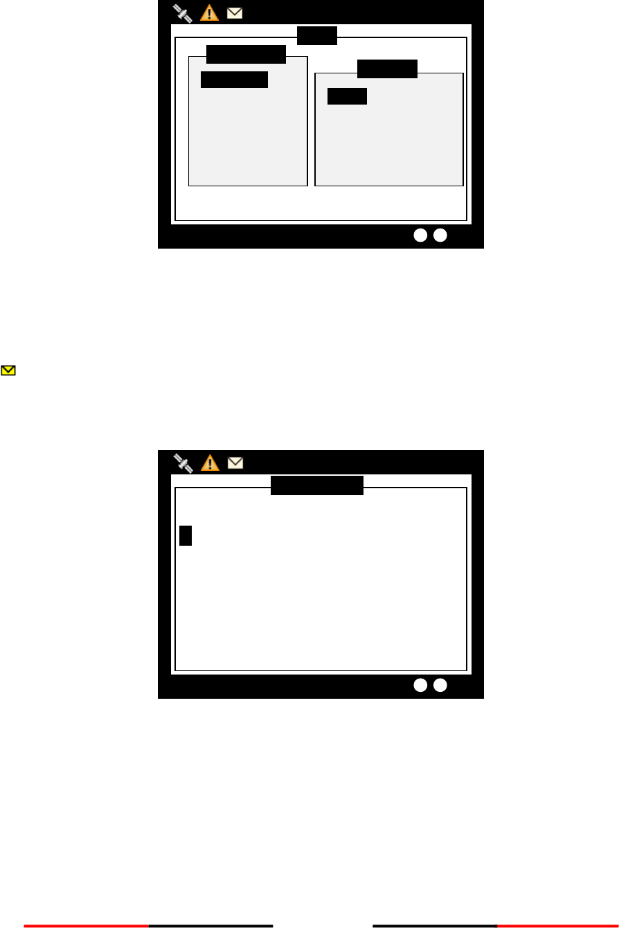
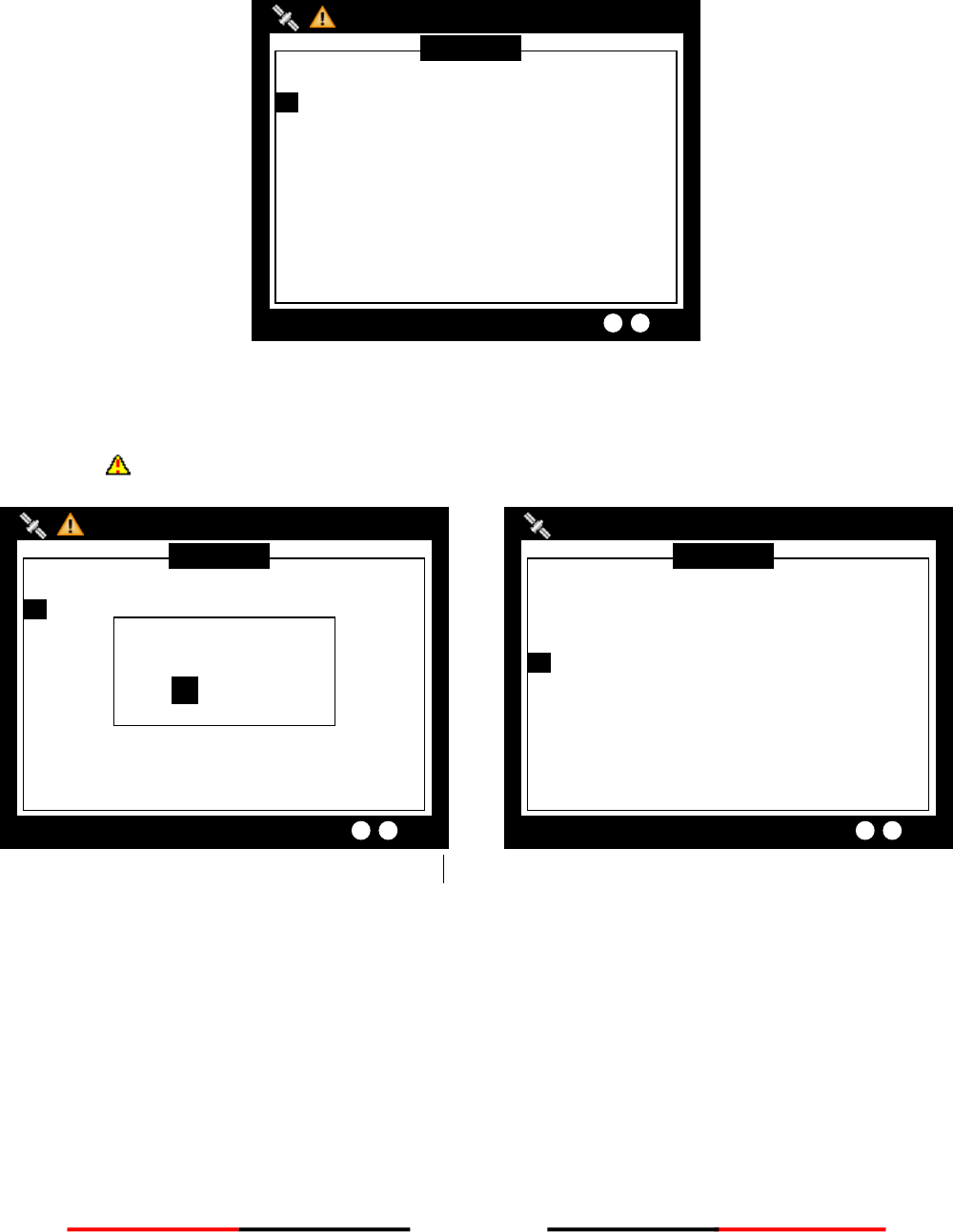
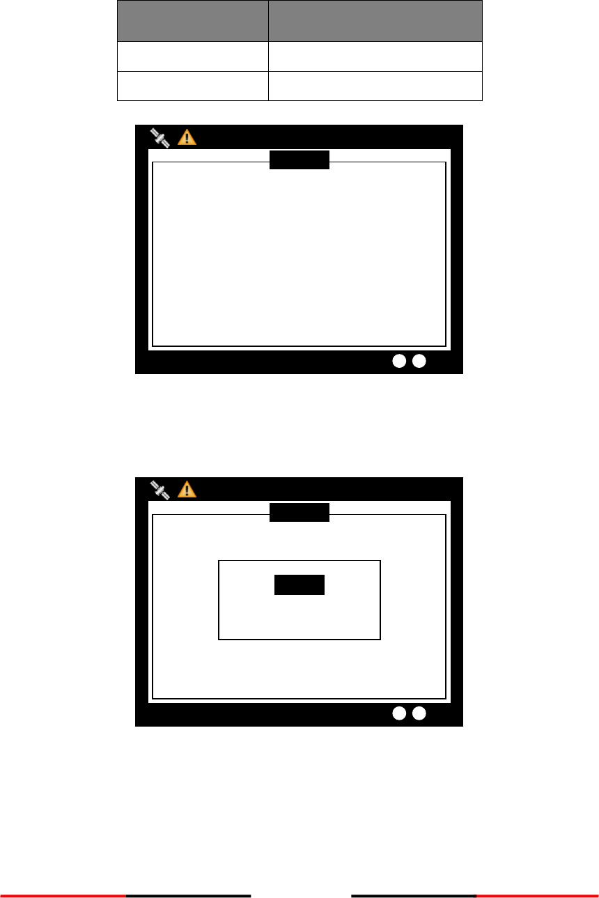
4.5 Messages
Figure 23 Message
4.5.1 Inbox SRM
You can read received SRM messages under Inbox. If there is any unread message, the upper left corner will
display , the new message icon.
Traversing list
Turn the knob to traverse the message list.
Figure 24 Traversing List
Message Inbox
2013/01/17 22:43:08
Dangerous Targets :0
------ MMSI ---- DATE/TIME ------- READ--
1. 222222222 T 22:41 YES
MENU
MESSAGES
NAV. STATUS
SHIP SETTING
TRANSCEIVER
SYS CONFIG
DIAGNOSTICS
MAIN MENU
INBOX
OUTBOX
BROADCAST SRM
ADDRESSED SRM
LR INBOX
MESSAGE
2013/01/17 07:18:11
Dangerous Targets :0
35
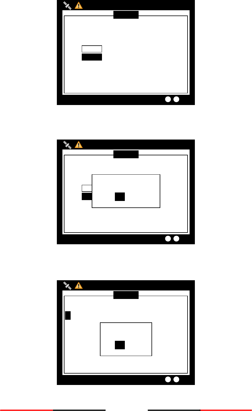
Highlight your choice and pressing down the knob to read message content.
Figure 25 Message Text
Message deletion
Pressing the MENU button will ask whether to delete the highlighted message. Turn knob to choose and press
knob to confirm your choice.
Figure 26 Message Deletion
Message Inbox
2013/01/17 22:43:08
Dangerous Targets :0
------ MMSI ---- DATE/TIME ------- READ--
1. 222222222 T 22:41 YES
Delete the item?
YES NO
Message TEXT
2013/01/17 22:43:09
Dangerous Targets :0
MMSI 222222222
TX TYPE Broadcast
DEST. MMSI N/A
TIME 2013/01/17 22:41:17
TEXT SART TEST
READ YES
36
4.5.2 Outbox SRM
You can read sent SRM messages under OUTBOX. Below are key functions under OUTBOX.
Traversing List
Turn the knob to traverse the message list.
Figure 27 Traversing List
View message
Highlight your choice and pressing down the knob to view message content.
Figure 28 View Message
Message TEXT
2013/01/17 22:43:39
Targets Received :10
MMSI 211111111
TX TYPE Addressed
DEST. MMSI 137131100
TIME 2013/01/17 22:42:11
TEXT GROUNDING
TX OK YES
RX ACK YES
ABK INFO No ACK by the addressed AIS
Message Outbox
2013/01/17 22:44:22
Dangerous Targets :0
----- MESSAGE ----- DATE/TIME -- TX --ACK
1. GROUNDING T 22:44 Y Y
2. SOS… T 22:43 Y --
37
Message deletion
Pressing the MENU button will ask whether to delete the highlighted message. Turn knob to choose and press
MENU to confirm the decision.
Figure 29 Message Deletion
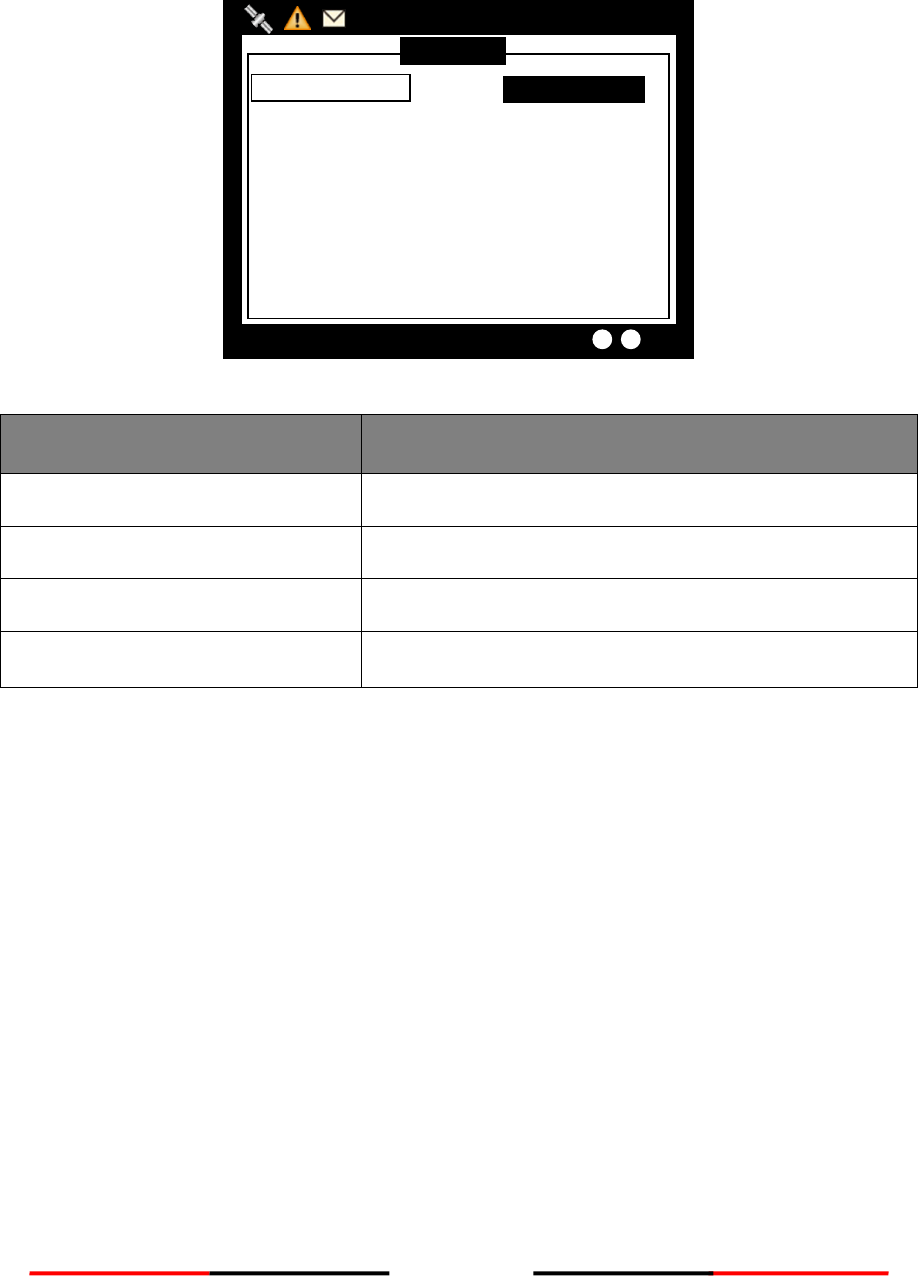
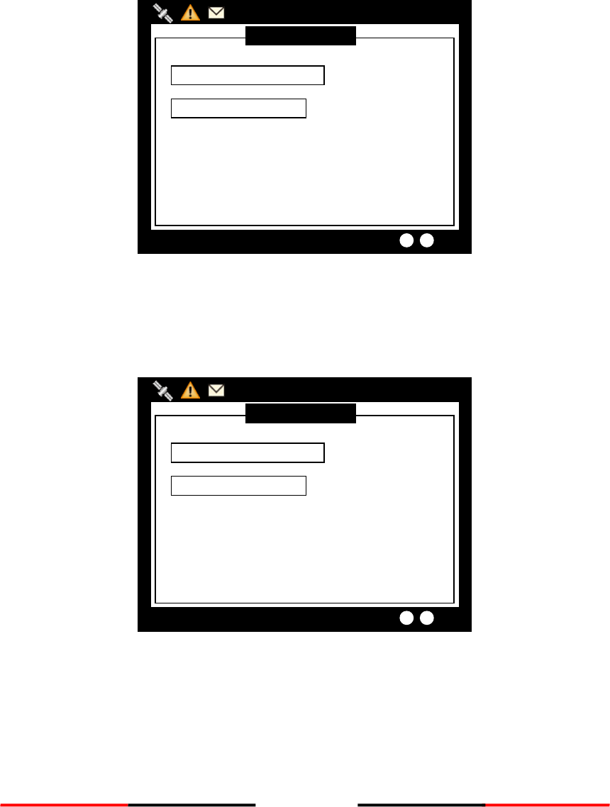
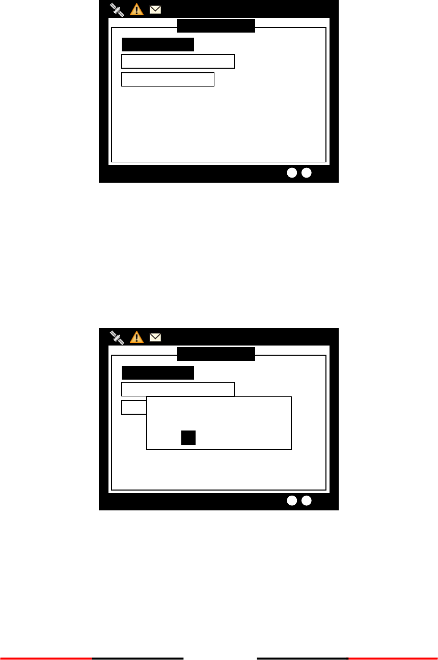
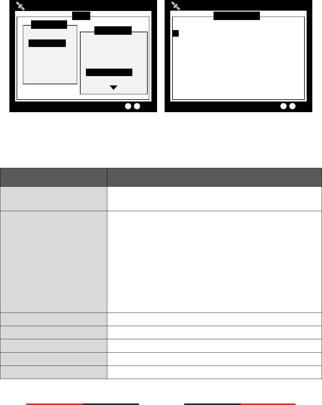
4.5.3 Broadcast SRM
Use this menu to send a Pre-defined or custom message. Turn the knob to traverse all available option.
Maximum length for the customized message is 90 characters.
Figure 30 Broadcast SRM
BROADCAST SRM
2013/01/17 07:18:11
Dangerous Targets :0
CUSTOMIZE TEXT
[ ]
[ ]
[ ]
TRANSMIT CHANNEL < ALTERNATE >
Message Outbox
2013/01/17 22:44:22
Dangerous Targets :0
----- MESSAGE ----- DATE/TIME -- TX --ACK
1. GROUNDING T 22:44 Y Y
2. SOS… T 22:43 Y --
Delete the item?
YES NO
38
Selecting SRM channel
SRM channel selection is the first option in the screen. Highlight it and press the knob to enter the option.
Turn the knob to change the setting.
Figure 31 Select SRM Channel
Once finish the settings, press the knob again to return.
Figure 32 Finish Setting
BROADCAST SRM
2013/01/17 07:18:11
Dangerous Targets :0
CUSTOMIZE TEXT
[ ]
[ ]
[ ]
TRANSMIT CHANNEL < ALTERNATE >
BROADCAST SRM
2013/01/17 07:18:11
Dangerous Targets :0
CUSTOMIZE TEXT
[ ]
[ ]
[ ]
TRANSMIT CHANNEL < ALTERNATE >
39
Using Predefined-Sentence
You may use PRE-SENTENCE option to select a pre-defined message sentences or a customized text. Press the
knob to enter and turn the knob to switch sentence selections, and then press the knob to confirm. To use a
customized sentence, turn selection to <Other>, and remember to enter you customized text at the
CUSTOMIZE TEXT option.
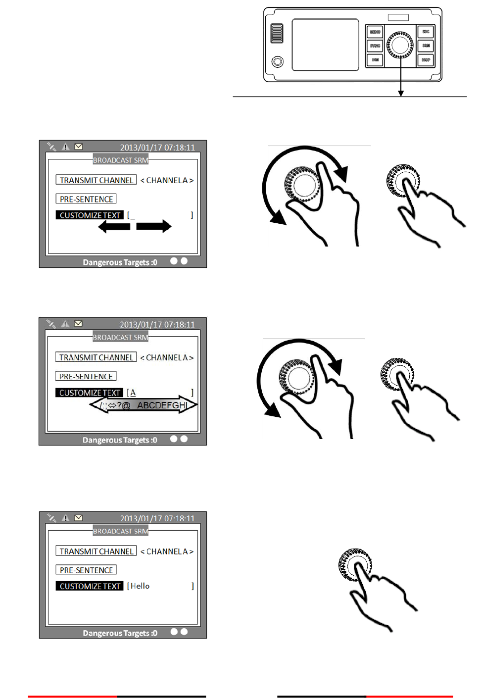
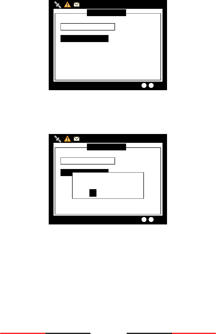
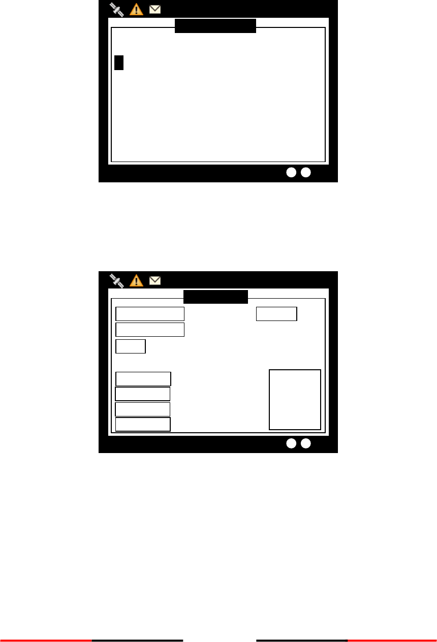
Entering SRM customized text
Press the knob to enter text input mode, then turn the knob to traverse character position on the text.
Figure 33 SRM Customized Text
Choose a text location, and then press the knob to enter text input mode. Turn the knob to select a character,
and then press the knob to confirm and to return. Repeat these steps till all desired characters are entered.
Figure 34 Enter Customized Text
BROADCAST SRM
2013/01/17 07:18:11
Dangerous Targets :0
CUSTOMIZE TEXT
[A ]
[ ]
[ ]
TRANSMIT CHANNEL < CHANNEL A >
BROADCAST SRM
2013/01/17 07:18:11
Dangerous Targets :0
CUSTOMIZE TEXT
[ ]
[ ]
[ ]
TRANSMIT CHANNEL < CHANNEL A >
40
When finished, press ESC to return to BROADCAST SRM menu.
Figure 35 Finish Customized Text
When done with all settings, pressing MENU or ESC to leave and the system will ask whether to send the
message. Select OK to send, CANCEL to cancel and return to main menu.
Figure 36 Send Message
BROADCAST SRM
2013/01/17 07:18:11
Dangerous Targets :0
CUSTOMIZE TEXT
[A ]
[ ]
[ ]
TRANSMIT CHANNEL < CHANNEL A >
Send Message?
OK CANCEL
BROADCAST SRM
2013/01/17 07:18:11
Dangerous Targets :0
CUSTOMIZE TEXT
[A ]
[ ]
[ ]
TRANSMIT CHANNEL < CHANNEL A >
41
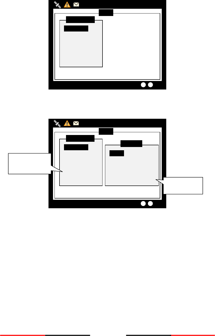
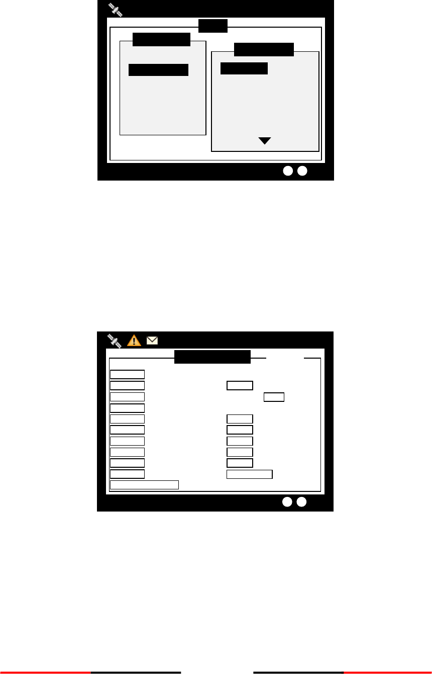
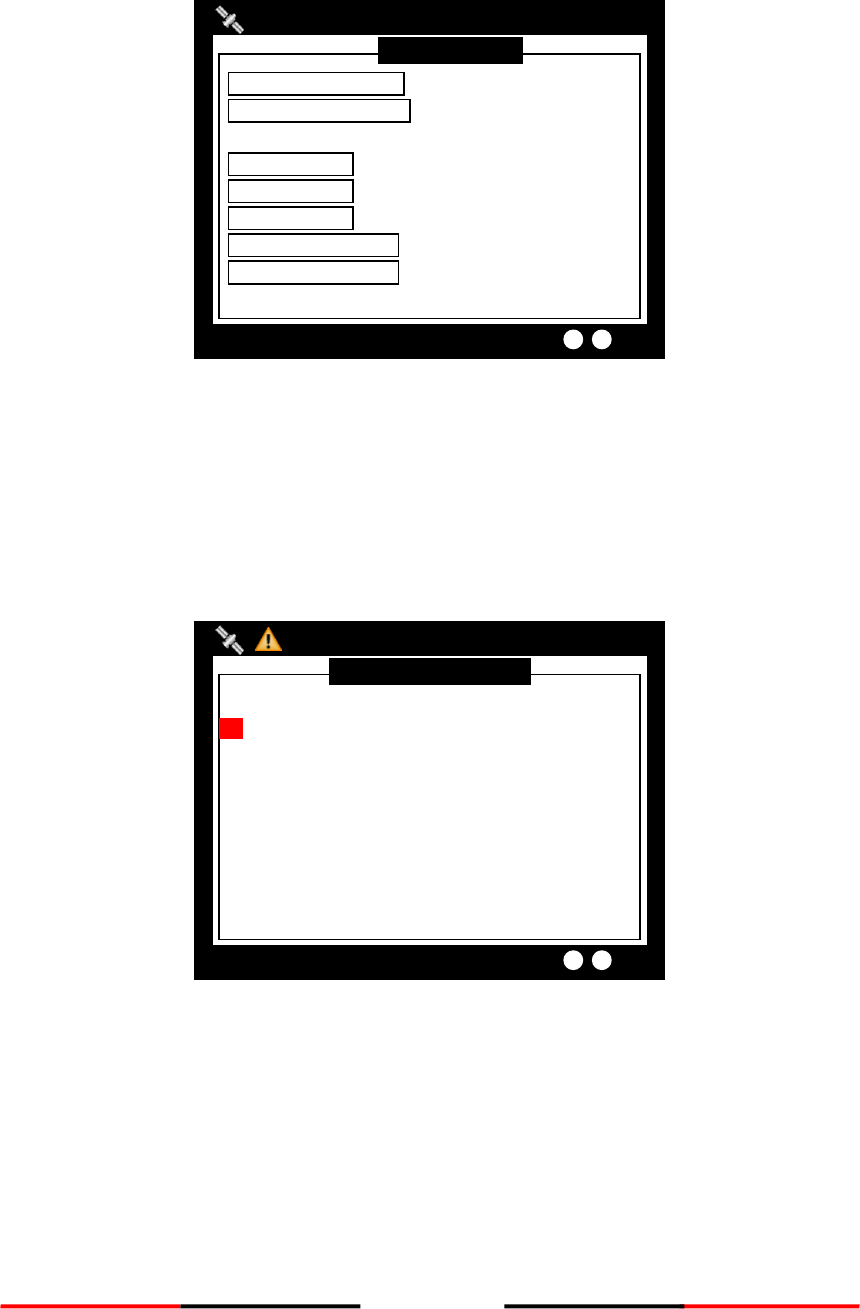
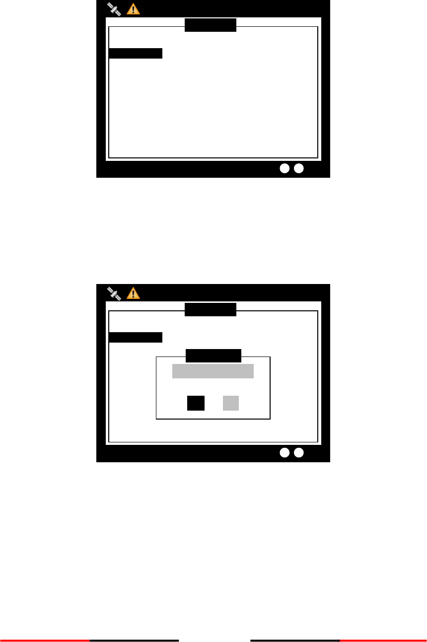
4.5.4 Addressed SRM
Press the knob button on ADDRESSED SRM will remind to select a target to send.
Figure 37 Addressed SRM
Pressing the knob will bring up the vessel list.
Figure 38 AIS Target List
AIS TARGET LIST
2013/01/17 22:44:22
Dangerous Targets :0
[013] - NAME/MMSI ---ET-- BRG(°) -- RNG(NM)
RNG
1. 211111161 1s 321 39.54
2. 211111561 1s 314 31.96
3. TEST05 1s 143 19.22
4. TEST10 2s 8 52.66
5. TEST03 1s 293 20.45
6. TEST06 1s 30 30.84
7. TEST08 2s 342 58.81
8. 211111461 3s 274 39.97
9. 211111161 3s 321 39.54
10. TEST02 4s 325 91.62
MENU
MESSAGES
NAV. STATUS
SHIP SETTING
TRANSCEIVER
SYS CONFIG
DIAGNOSTICS
MAIN MENU
INBOX
OUTBOX
BROADCAST SRM
ADDRESSED SRM
LR INBOX
MESSAGE
2013/01/17 07:18:11
Dangerous Targets :0
Select Target
OK
Set SRM Alarm
42
Select the target vessel by pressing the knob to customize SRM sending. Maximum length for the customized
message is 85 characters.
Figure 39 Customize SRM
When changing Destination MMSI, choose a text location, and then press the knob to enter text input mode.
Turn the knob to select a character, and then press the knob to confirm and to return. Repeat these steps till
all desired characters are entered.
When done with all settings, press MENU or ESC to leave. The system will ask whether to send the message.
Select OK to send, CANCEL to cancel and return to main menu.
Figure 40 Send Message
ADDRESSED SRM
2013/01/17 07:18:11
Dangerous Targets :0
TRANSMIT CHANNEL <ALTERNATE>
DESTN. MMSI [ 222222222 ]
CUSTOMIZE TEXT
[A ]
[ ]
[ ]
[ ]
Send Message?
OK CANCEL
ADDRESSED SRM
2013/01/17 07:18:11
Dangerous Targets :0
TRANSMIT CHANNEL <ALTERNATE>
DESTN. MMSI [ 222222222 ]
CUSTOMIZE TEXT
[ ]
[ ]
[ ]
43
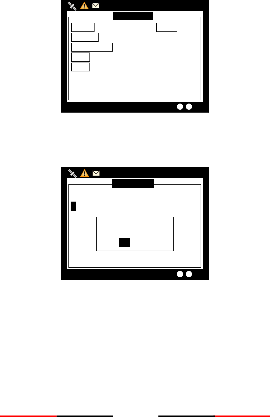
4.5.5 Long Range SRM
LONG RANGE SRM holds all received Long Range Interrogation messages.
Turn the knob to traverse the message list.
Figure 41 Long Range SRM
Reading message
Press the knob to read the interrogation message content. When finished reading, press ESC to leave the page.
Figure 42 Reading Message
Message TEXT
2013/01/17 23:26:55
Targets Received :10
Requ. MMSI 619931371
211111111
Requ. NAME BSHTEST
TIME 2011/01/17 23:25:45
TX ACK YES
LAT(NE) 20.383333
Interrogation area
LON(NE) 123.966667
LAT(SW) 19.583334
LON(SW) 123.049995
NE
SW
LR Message Inbox
2013/01/17 23:26:20
Dangerous Targets :0
----- MMSI ------- DATE/TIME ------ ACK---
1. 619931371 T 23:25 YES

44
Message deletion
Under the message list, pressing MENU will ask whether to delete the message. Turn knob to choose and
press knob to confirm your choice.
Figure 43 Message Deletion
LR Message Inbox
2013/01/17 23:27:10
Dangerous Targets :0
----- MMSI ------- DATE/TIME ------ ACK---
1. 619931371 T 23:25 YES
Delete the item?
YES NO
45
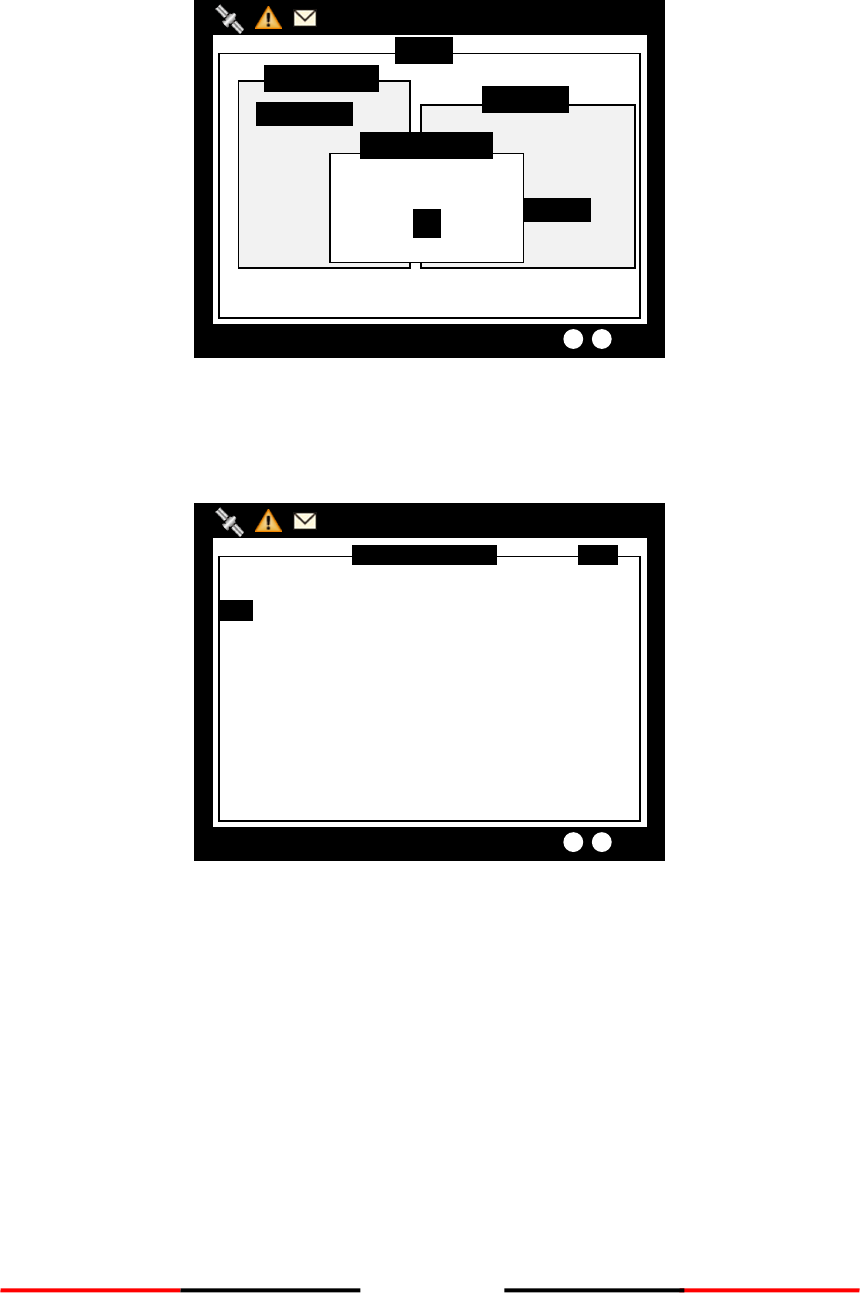
4.6 Navigation Status
Figure 44 Navigation Status
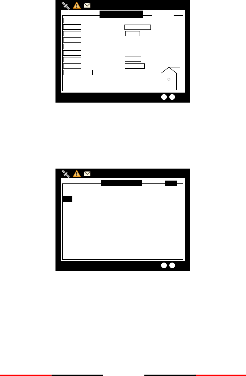
4.6.1 Own Ship
This option displays the full information on your ship, including both dynamic and static data. Turning the
knob, can view dynamic and static information alternatively.
Static data
Figure 45 Static Data
OWN SHIP <1/2>
2013/01/17 22:43:39
Dangerous Targets :0
NAME AMEC09
CALL CS09
MMSI 211111111 [CLASS A]
NAV. Under way using engine
LON 121°45’00”E
LAT 025°09’25”N
SOG 12.00Kn
COG 298.0°
ROT N/A
000/023
EPFS GPS
RNG Own Ship
BRG Own Ship
CPA 5 NM (set)
HDG N/A
TCPA 10 min (set)
P.A. Hi
Manoeuvre Ind. not available
RAIM In use
TX POWER 12.5 W
MENU
MESSAGES
NAV. STATUS
SHIP SETTING
TRANSCEIVER
SYS CONFIG
DIAGNOSTICS
MAIN MENU
OWN SHIP
AIS TARGETS
REGION LIST
ALARM LIST
ALARM HISTORY
SENSOR STATUS
NAV. STATUS
2013/01/17 07:18:11
Dangerous Targets :0
46
Dynamic data
Figure 46 Dynamic Data
4.6.2 AIS Targets
This option displays all receive AIS messages of other boats. It can show their dynamic or static information.
Turn the knob to select an AIS target.
Figure 47 AIS Targets
AIS TARGET LIST
2013/01/17 22:44:22
Dangerous Targets :0
[013] - NAME/MMSI ---ET-- BRG(°) -- RNG(NM)
RNG
1. 211111161 1s 321 39.54
2. 211111561 1s 314 31.96
3. TEST05 1s 143 19.22
4. TEST10 2s 8 52.66
5. TEST03 1s 293 20.45
6. TEST06 1s 30 30.84
7. TEST08 2s 342 58.81
8. 211111461 3s 274 39.97
9. 211111161 3s 321 39.54
10. TEST02 4s 325 91.62
OWN SHIP <2/2>
2013/01/17 22:43:39
Dangerous Targets :0
CALL 0001
MMSI 211111111
CARGO N/A or Harmless
TYPE Vessel-Pleasure craft
NAME AMEC
DEST TPE_259
ETA 02/25 01:02
BEAM 87m
Pos. Quality Position with
RAIM <=10 m
000/023
DRAUGHT 1.0m
IMO 111111111
DTE AVAILABLE
[CLASS A]
A:40m B:41m C: 42m D:45m
A
B
C
D
LENGTH 81m
47
Press the knob, to read the selected vessel dynamic information.
Figure 48 Ship Information
Press the knob again to read static information.
Figure 49 Static Information
SHIP DETAIL <2/2>
2013/01/17 22:43:39
Dangerous Targets :0
CALL TEST12
MMSI 211000601
CARGO N/A or Harmless
TYPE Undefined ship type!
NAME TEST12
DEST DEST_12
ETA 02/28 01:30
BEAM 64m
Pos. Quality Position < 10 m
006/023
DRAUGHT 12.5m
IMO 357059601
DTE N/A
[CLASS A]
A:160m B:34m C: 22m D:42m
A
B
C
D
LENGTH 194m
SHIP DETAIL <1/2>
2013/01/17 22:43:39
Dangerous Targets :0
NAME TEST12
CALL TEST12
MMSI 211000601 [CLASS A]
NAV. Under way using engine
LON 121°54’59”E
LAT 025°12’37”N
SOG 26.00Kn
COG 350.8°
ROT N/A
006/023
EPFS Undefined
RNG 10.61NM
BRG 80°
CPA pass
HDG 351.8°
TCPA pass
P.A. Lo
Manoeuvre Ind. not available
RAIM Not in use
48
Adding Friend Ship
In the list, pressing MENU button will ask whether to add this vessel to your FRIEND SHIP list.
Figure 50 Adding Friend Ship
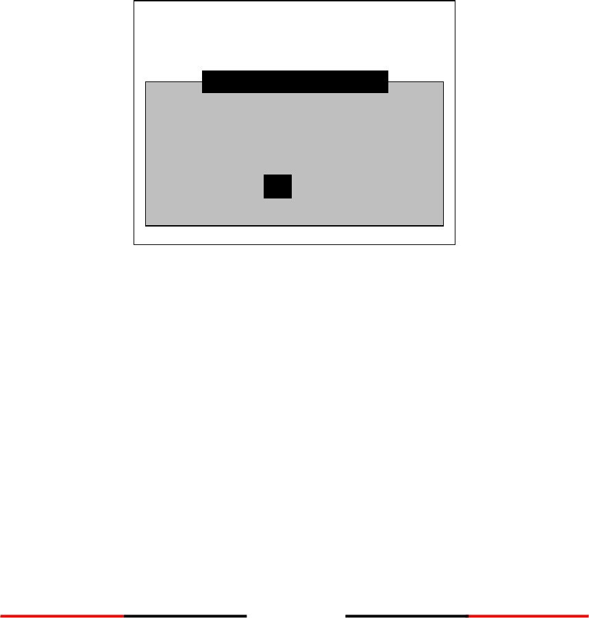
Sorting AIS Target List
Pressing the FUNC button can sort the list according to vessels’ MMSI, distance, or direction.
Figure 51 Sorting AIS Target List
In the screenshot above, the block A indicates the current sorting method.
By MMSI, in ascending order
By direction, in ascending order
By distance, in ascending order
AIS TARGET LIST
2013/01/17 22:44:22
Dangerous Targets :0
[013] - NAME/MMSI ---ET-- BRG(°) -- RNG(NM)
RNG
1. 211111161 1s 321 39.54
2. 211111561 1s 314 31.96
3. TEST05 1s 143 19.22
4. TEST10 2s 8 52.66
5. TEST03 1s 293 20.45
6. TEST06 1s 30 30.84
7. TEST08 2s 342 58.81
8. 211111461 3s 274 39.97
9. 211111161 3s 321 39.54
10. TEST02 4s 325 91.62
Add New Friend?
YES NO
Block A
AIS TARGET LIST
2013/01/17 22:44:22
Dangerous Targets :0
[013] - NAME/MMSI ---ET-- BRG(°) -- RNG(NM)
RNG
1. 211111161 1s 321 39.54
2. 211111561 1s 314 31.96
3. TEST05 1s 143 19.22
4. TEST10 2s 8 52.66
5. TEST03 1s 293 20.45
6. TEST06 1s 30 30.84
7. TEST08 2s 342 58.81
8. 211111461 3s 274 39.97
9. 211111161 3s 321 39.54
10. TEST02 4s 325 91.62
Add New Friend?
YES NO
49
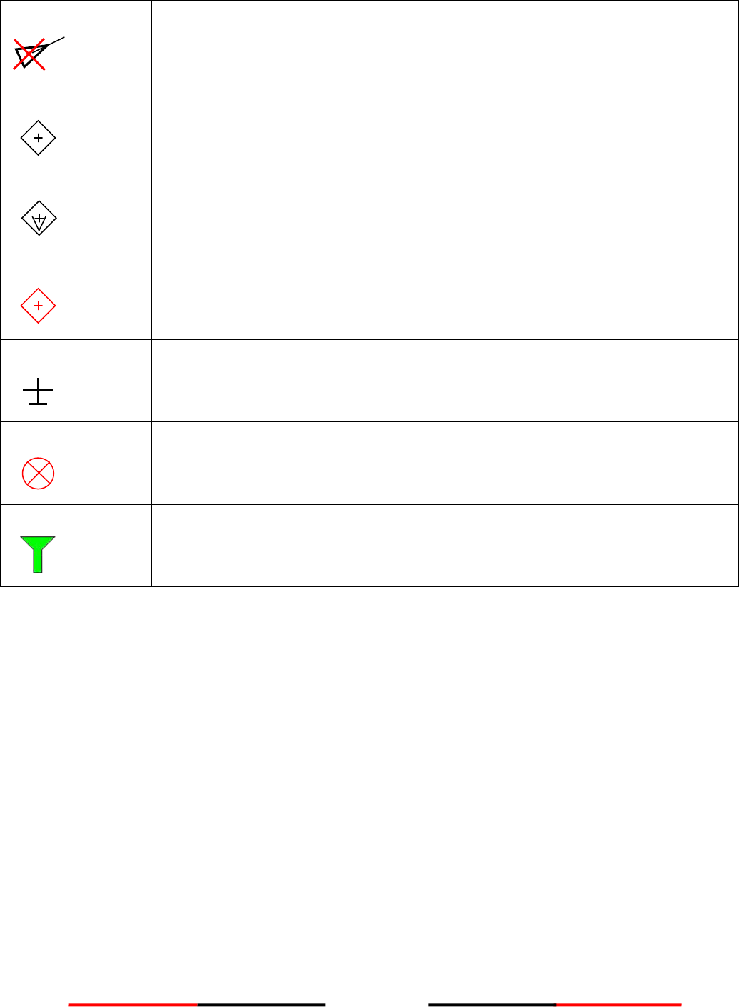
4.6.3 Region List
This option list all saved region information.
Figure 52 Region List
Turn the knob to traverse the list. Press the knob enables you to read the highlighted region information.
Figure 53 Region Setting
REGION [1] SETTING
2013/01/17 22:43:39
Targets Received: 10
LAT(NE) 020°24’00”N
LON(NE) 123°58’00”E
LAT(SW) 019°35’00”N
LON(SW) 123°04’00”E
T.Zone (NM) 5
Channel A 2023
Channel B 2023
TX/RX Mode TxA/ TxB/ RxA/ RxB
Addr/Broad ACA Sentence
Band Width 25K Hz
Power Low
Band Width 25K Hz
>TZ<
SW
NE
REGION SETTING LIST
2013/01/17 23:26:20
Dangerous Targets :0
--- Region No---- Source ------- Date/Hour --
Region 1 ACA 12/01/02
11
Region 2 ACA 12/01/02
11
Region 3 N/A 11/11/01
00
Region 4 N/A 11/11/01
00
Region 5 N/A 11/11/01
00
Region 6 N/A 11/11/01
00
Region 7 N/A 11/11/01
00
Region in Use [Region 9]
T. Zone Status [No ]
50
Modify region content
Press MENU at the region information page, enables you to modify the region information.
Figure 54 Modify Region Content
To save, pressing MENU or ESC will ask whether to save the changes.
If the region information is un-modifiable, saving does not change the original information.
Figure 55 Save Data
REGION LIST [1]
2013/01/17 22:43:39
Targets Received: 10
LAT(NE) [20]°[24]’[00]”<N>
LON(NE) [123]°[58]’[00]”<E>
LAT(SW) [19]°[35]’[00]”<N>
LON(SW) [123]°[04]’[00]”<E>
T.Zone (NM) [5]
Channel A [2023]
Channel B [2023]
TX/RX Mode <TxA/ TxB/ RxA/ RxB>
Band Width [25]
Power <High>
Band Width [25]
Save data?
YES NO
REGION LIST [1]
2013/01/17 22:43:39
Targets Received: 10
LAT(NE) [20]°[24]’[00]”<N>
LON(NE) [123]°[58]’[00]”<E>
LAT(SW) [19]°[35]’[00]”<N>
LON(SW) [123]°[04]’[00]”<E>
T.Zone (NM) [5]
Channel A [2023]
Channel B [2023]
TX/RX Mode <TxA/ TxB/ RxA/ RxB>
Band Width [25]
Power <High>
Band Width [25]
REGION [1] SETTING
2013/01/17 22:43:39
Targets Received: 10
LAT(NE) 020°24’00”N
LON(NE) 123°58’00”E
LAT(SW) 019°35’00”N
LON(SW) 123°04’00”E
T.Zone (NM) 5
Channel A 2023
Channel B 2023
TX/RX Mode TxA/ TxB/ RxA/ RxB
Addr/Broad ACA Sentence
Band Width 25K Hz
Power Low
Band Width 25K Hz
>TZ<
SW
NE
Edit Region?
YES NO
51
4.6.4 Alarm List
This command lists all current AIS ALR statuses.
Figure 56 Alarm List
By pressing MENU, enables you to send ACK message to AIS. If the ALR information has not yet responded, an
indication icon will appear on left upper corner till all ARL information is received.
Figure 57 Send Message
ALARM LIST
2013/01/17 22:44:22
Targets Received: 10
----- ID -- Text ------------------------------ ACK
1. 07. UTC sync invalid YES
2. 32. Heading lost/invalid YES
3. 35. No valid ROT information YES
ALARM LIST
2013/01/17 22:44:22
Targets Received: 10
----- ID -- Text ------------------------------ ACK
1. 07. UTC sync invalid NO
2. 32. Heading lost/invalid NO
3. 35. No valid ROT information NO
Confirm Message?
OK CANCEL
ALARM LIST
2013/01/17 22:44:22
Targets Received: 10
----- ID -- Text ------------------------------ ACK
1. 07. UTC sync invalid NO
2. 32. Heading lost/invalid NO
3. 35. No valid ROT information NO
52
4.6.5 Alarm History
This command lists all recorded alarm and its time of occurrence.
Figure 58 Alarm History
4.6.6 Sensor Status
Display sensor statuses:
SENSOR
STATUS
POSITION STATUS
EXT. DGNSS / INT. DGNSS MSG.17 /
EXT. GNSS / INT. GNSS / NO GPS
POSITION QUALITY
No position
Manual position
Dead reckoning position
valid position with no time stamp
Position > 10m
Position with RAIM > 10 m
Position <= 10 m
Position with RAIM <= 10 m
Outdated position > 200 m
UTC STATUS
VALID / LOST
COG STATUS
INT. COG / EXT. COG / LOST
SOG STATUS
INT. SOG / EXT. SOG / LOST
HEADING STATUS
VALID / LOST
ROT STATUS
VALID / OTHER ROT / LOST
ALARM HISTORY
2013/01/17 22:44:22
---- ID -- Text ----------------------DATE-- TIME-
1. 35. No valid ROT 12/24 09:27
2. 32. Heading lost 12/24 09:27
3. 07. UTC sync invalid 12/24 09:27
Targets Received: 10
MENU
MESSAGES
NAV. STATUS
SHIP SETTING
TRANSCEIVER
SYS CONFIG
DIAGNOSTICS
MAIN MENU
OWN SHIP
AIS TARGETS
REGION LIST
ALARM LIST
ALARM HISTORY
SENSOR STATUS
NAV. STATUS
2013/01/17 07:18:11
Dangerous Targets :0
53
The channel status below records TXT message received times.
AIS: Channel management parameters changed.
Figure 59 Sensor Status
4.6.7 Dangerous List
Any vessel with less than the safe encountering time (TCPA) and distance (CPA) will be listed in DANGEROUS
LIST for navigation purposes and safety references.
Figure 60 Dangerous List
DANGEROUS TARGETS
2013/01/17 22:44:22
[003]-- NAME ------ MMSI -- CPA ----- TCPA -
1. TEST01 210000000 3.84 35.98
TX POWER LEVEL: 12.5W
SENSOR STATUS
2013/01/17 22:43:39
TX POWER LEVEL: 12.5W
POSITION STATUS EXT. GNSS
UTC STATUS LOST
COG STATUS EXT. COG
SOG STATUS EXT. SOG
HEADING STATUS VALID
ROT STATUS VALID
--DATE TIME--CHANNEL PARAMETER CHANGE--
POSITION QUALITY Position with RAIM
<= 10 m
54
Turn the knob to select a vessel and press to read its information.
Figure 61 Ship Detail (1)
Press the knob again to go the second page for more detail.
Figure 62 Ship Detail (2)
SHIP DETAIL <2/2>
2013/01/17 22:43:39
CALL TEST
MMSI 210000000
CARGO Unknown Cargo!
TYPE Vessel-Pleasure craft
NAME TEST01
DEST TPI
ETA 02/28 01:30
BEAM 0m
Pos. Quality Position with
RAIM <= 10 m
006/023
DRAUGHT N/A
IMO 000000000
DTE N/A
[CLASS A]
A:0m B:0m C: 0m D:0m
A
B
C
D
LENGTH 0m
TX POWER LEVEL: 12.5W
SHIP DETAIL <1/2>
2013/01/17 22:43:39
TX POWER LEVEL: 12.5W
NAME TEST01
CALL TEST
MMSI 210000000 [CLASS A]
NAV. AIS-SART
LON 121°45’00”E
LAT 025°09’25”N
SOG 3.00Kn
COG 000.0°
ROT 0.0°
001/001
EPFS GPS
RNG 5.43NM
BRG 270°
CPA 3.84 NM
HDG 125.0°
TCPA 54.31 min
P.A Hi
Manoeuvre Ind. not available
RAIM In use
55
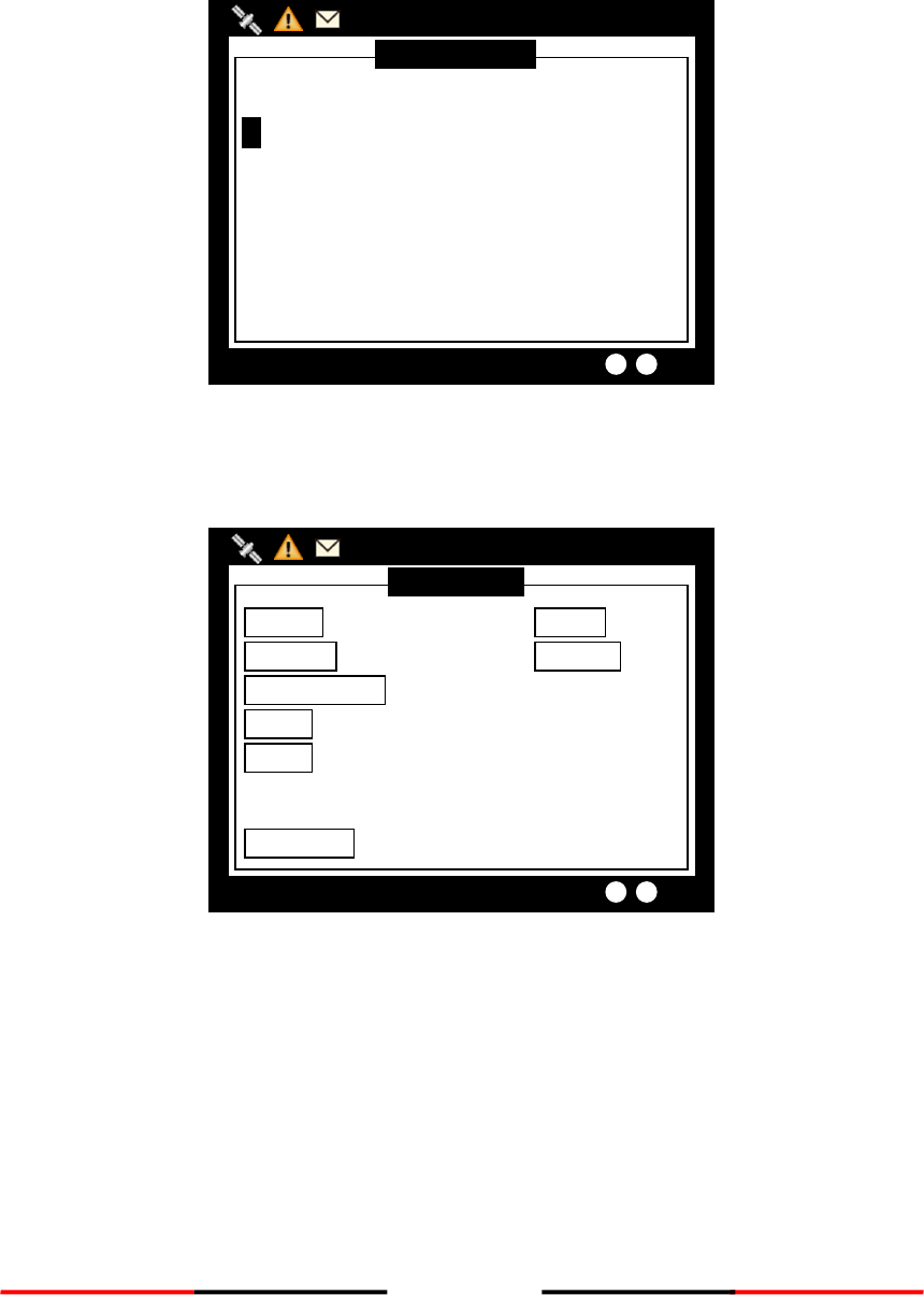
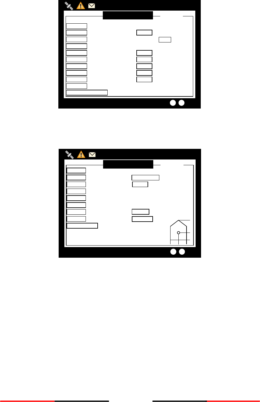
4.6.8 MOB List
This command enables adding, removing, or modifying of MOB list entries.
Button
Action
MENU
Add, Remove entry
Knob Button
Modify a selected entry
Figure 63 MOB List (1)
After pressing the Menu button, a prompt appears.
Figure 64 MOB List (2)
Select ADD NEW to enter edit mode.
MOB LIST
2013/01/17 17:04:39
TX POWER LEVEL: 12.5W
[000]-- ID ------ NAME --------------------------
DELETE
ADD NEW
MOB LIST
2013/01/17 17:04:38
TX POWER LEVEL: 12.5W
[000]-- ID ------ NAME --------------------------
56
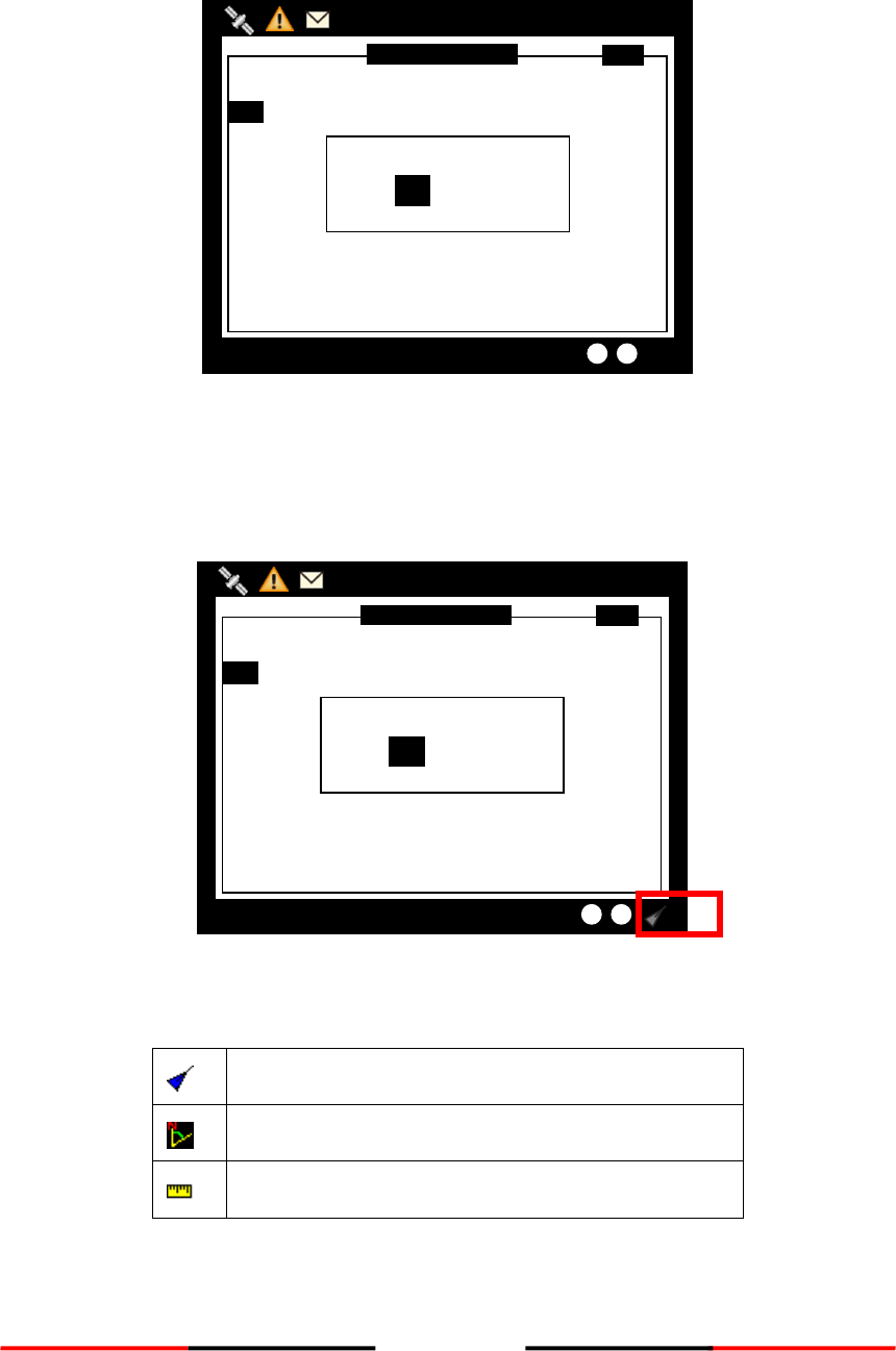
Figure 65 MOB List (3)
When finished entering MMSI and the assigned name, press MENU or ESC to save or leave without saving.
Figure 66 MOB List (4)
After finished adding, the list now has the new MMSI. To modify an entry, only need to press the knob to
enter edit mode.
Figure 67 MOB List (5)
MOB LIST
2013/01/17 17:04:42
TX POWER LEVEL: 12.5W
[000]-- ID ------ NAME --------------------------
1. 970000001 TEST
EDIT MOB
YES NO
MOB LIST
2013/01/17 17:04:41
TX POWER LEVEL: 12.5W
MMSI [970000001]
NAME [TEST ]
Save Data?
YES NO
MOB LIST
2013/01/17 17:04:40
TX POWER LEVEL: 12.5W
MMSI [970000001]
NAME [TEST ]
57
4.6.9 Friend Ships
This command displays the list of all registered friend ships.
Figure 68 Buddy List
Turn the knob to traverse the message list.
Press the MENU button for deletion on the highlighted ship. Turn knob to choose and press knob to confirm
your choice.
Figure 69 Delete the Item
BUDDY LIST
2013/01/17 22:44:22
Targets Received: 10
--- MMSI -------- SHIP NAME -------------------
211111211 TEST02
211111311 TEST04
211111411 TEST06
Delete the item?
YES NO
2111111211
BUDDY LIST
2013/01/17 22:44:22
Targets Received: 10
--- MMSI -------- SHIP NAME -------------------
211111211 TEST02
211111311 TEST04
211111411 TEST06

58
4.7 Ship Setting
This sub-menu lists all the ship information settings of your ship. There are a total of 4 setting commands.
Figure 70 Ship Setting
4.7.1 Own Ship
To access OWN SHIP setting, you are required to enter your password (The default password is 0000).
Choose a text location, and then press the knob to enter text input mode. Turn the knob to select a character,
and then press the knob to confirm and to return. Repeat these steps till all desired characters are entered.
After entering the password, press down the knob for 3 seconds to confirm.
Figure 71 Own Ship
MENU
MESSAGES
NAV. STATUS
SHIP SETTING
TRANSCEIVER
SYS CONFIG
DIAGNOSTICS
MAIN MENU
OWN SHIP
VOYAGE
CPA/TCPA
CHANGE MMSI/IMO
RETRY TIMES
SHIP SETTING
2013/01/17 07:18:11
Dangerous Targets :0
Please enter the password and
hold KNOB for confirmation.
[ **** ]
PASSWORD
MENU
MESSAGES
NAV. STATUS
SHIP SETTING
TRANSCEIVER
SYS CONFIG
DIAGNOSTICS
MAIN MENU
OWN SHIP
VOYAGE
CPA/TCPA
CHANGE MMSI/IMO
RETRY TIMES
SHIP SETTING
2013/01/17 07:18:11
Dangerous Targets :0
59
If the password is correct, the system will proceed to the settings page, else a system message will indicate
that the password is wrong.
Figure 72 Own Ship Setting
Pressing MENU or ESC button will ask whether to save data. Turn knob to choose and press knob to confirm
your choice.
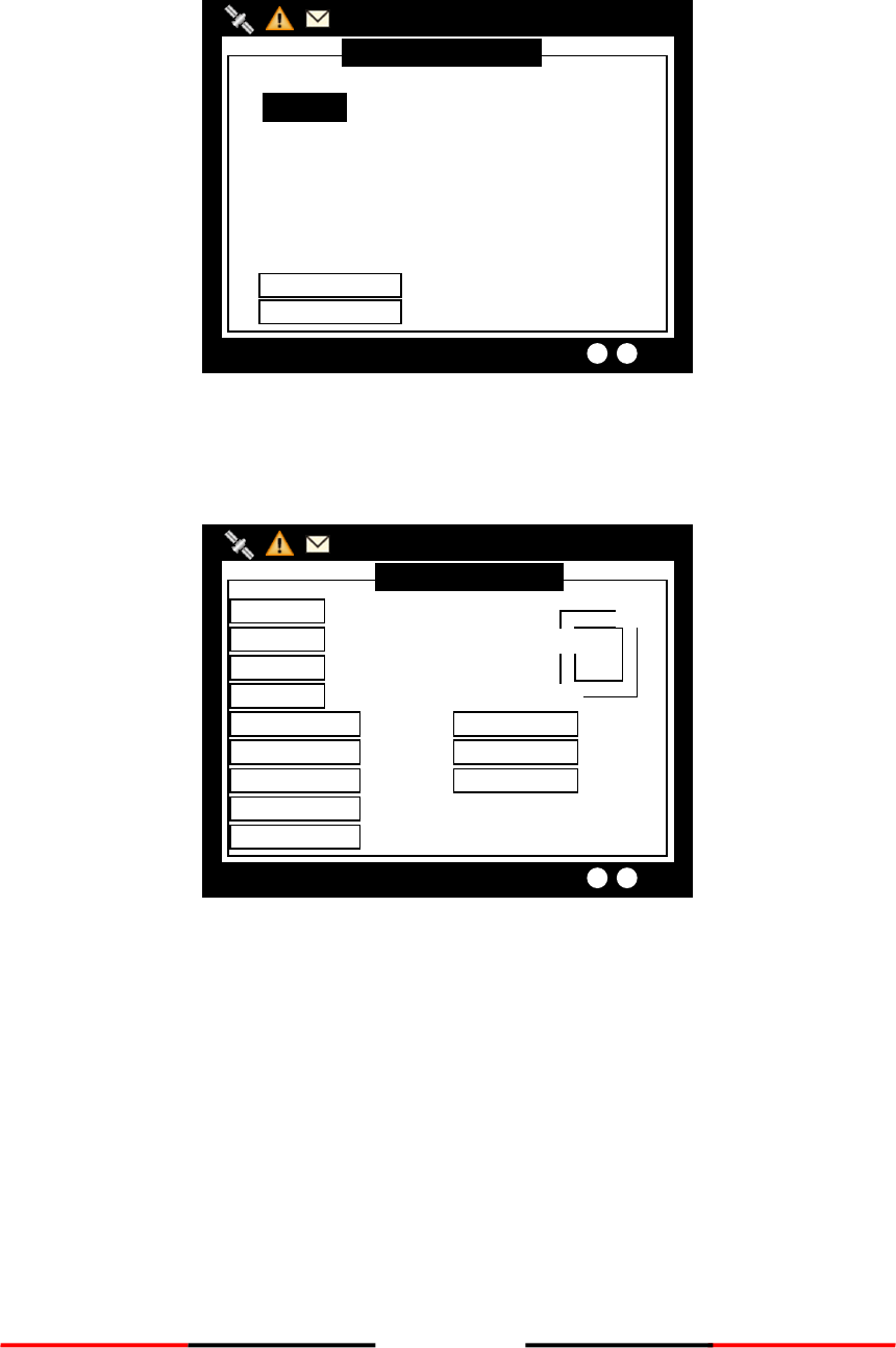
4.7.2 Voyage
VOYAGE provides navigation functionalities, such as navigation destination, time of arrival, navigation status,
etc.
Figure 73 Voyage Setting
Pressing MENU or ESC button will ask whether to save data. Select YES to save and exit, or NO to exit without
saving.
VOYAGE SETTING
2013/01/17 22:43:39
Targets Received: 10
ETA [00/00 00:00]
CARGO <N/A or Harmless>
NAV. <Under way using engine>
PERSON [0000]
DRAUGHT(m) [+00.0]
DESTIN [ ]
Save data?
YES NO
VOYAGE SETTING
2013/01/17 22:43:39
Targets Received: 10
ETA [00/00 00:00]
CARGO <N/A or Harmless>
NAV. <Under way using engine>
PERSON [0000]
DRAUGHT(m) [+00.0]
DESTIN [ ]
SHIP SETTING
2013/01/17 22:43:39
Dangerous Targets :10
SHIP NAME [AMEC ]
SHIP TYPE <Pilot vessel>
INTERNAL ANT. POS. (m)
EXTERNAL ANT. POS. (m)
A
B
C
D
A [000]
B [000]
C [00]
D[00]
A [000]
B [000]
C [00]
D[00]
CALL SIGN [0001 ]
Save data?
YES NO
SHIP SETTING
2013/01/17 22:43:39
SHIP NAME [AMEC ]
SHIP TYPE <Pilot vessel>
INTERNAL ANT. POS. (m)
EXTERNAL ANT. POS. (m)
A
B
C
D
A [000]
B [000]
C [00]
D[00]
A [000]
B [000]
C [00]
D[00]
CALL SIGN [0001 ]
Dangerous Targets :10
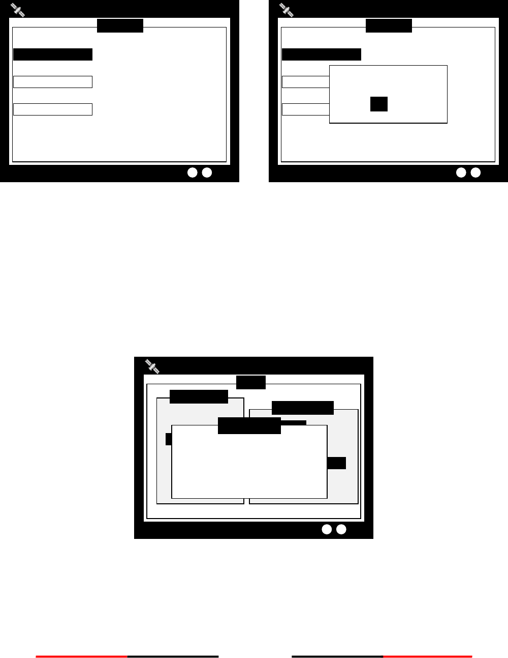
60
4.7.3 CPA/TCPA
This command holds the settings to configure dangerous ship criteria (TCPA and CPA) and the alarm.
Figure 74 CPA/TCPA
Pressing MENU or ESC button will ask whether to save data. Select YES to save and exit, or NO to exit without
saving.
4.7.4 Change MMSI/IMO
Before entering Change MMSI/IMO page, please enter the password (Default password: “0000”). Press and
hold the knob for 3 seconds as confirmation.
Figure 75 Change MMSI/IMO (1)
This command provides settings to enter MMSI and IMO.
Turn knob to traverse the items and press to enter the setting screen.
MENU
MESSAGES
NAV. STATUS
SHIP SETTING
TRANSCEIVER
SYS CONFIG
DIAGNOSTICS
MAIN MENU
OWN SHIP
VOYAGE
CPA/TCPA
Change MMSI/IMO
RETRY TIMES
SHIP SETTING
2013/01/17 07:18:11
Dangerous Targets :0
Please enter the password and
hold KNOB for confirmation.
[ **** ]
PASSWORD
CPA/TCPA
2013/01/17 22:43:39
Targets Received: 10
TCPA (min) [90]
ALARM <OFF>
CPA (NM) [95]
Save data?
YES NO
CPA/TCPA
2013/01/17 22:43:39
Targets Received: 10
TCPA (min) [90]
ALARM <OFF>
CPA (NM) [95]
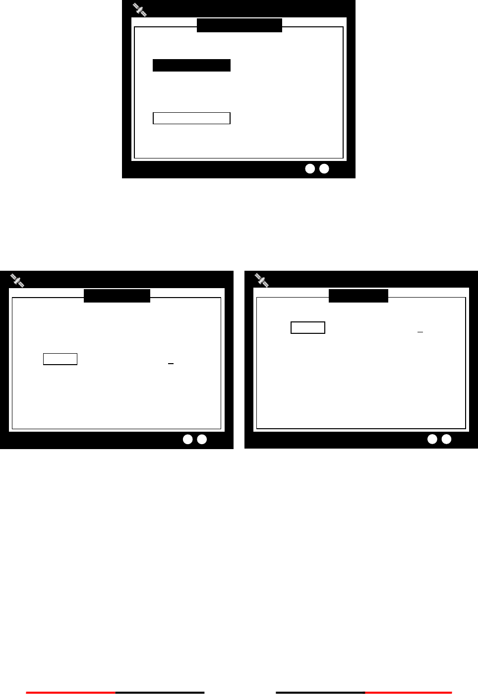
61
Figure 76 Change MMSI/IMO (2)
Turn the knob to change the position and press knob to enter text input mode. Turn the knob to change value
and press knob again to confirm. Repeat these procedures till all values are entered.
Double check to ensure value is entered correctly and press MENU or ESC to save.
Figure 77 MMSI/IMO Setting (3)
The system will ask for your confirmation.
IMO SETTING
2013/01/17 07:18:11
IMO [000000000]
Targets Received: 10
MMSI SETTING
2013/01/17 22:43:39
Targets Received: 10
MMSI [000000000]
MMSI RANGE: 20000000~799999999 or
982000000~987000000
Change MMSI/IMO
2013/01/17 22:43:39
Targets Received: 10
IMO [000000000]
MMSI [000000000]

62
Figure 78 Save Data
4.7.5 Retry Times
In order to resend messages when the transmitted Message 6 or Message 12 receives no response of Message
7 or Message 13, set the Retry Times to set the resending times.
Figure 79 Retry Times
Set Retry Times
2013/01/17 22:43:39
Targets Received: 10
Retry Times <3>
IMO SETTING
2013/01/17 07:18:11
IMO [000000000]
Targets Received: 10
Save data?
YES NO
MMSI SETTING
2013/01/17 22:43:39
Targets Received: 10
MMSI [000000000]
MMSI RANGE: 20000000~799999999 or
982000000~987000000
Save data?
YES NO
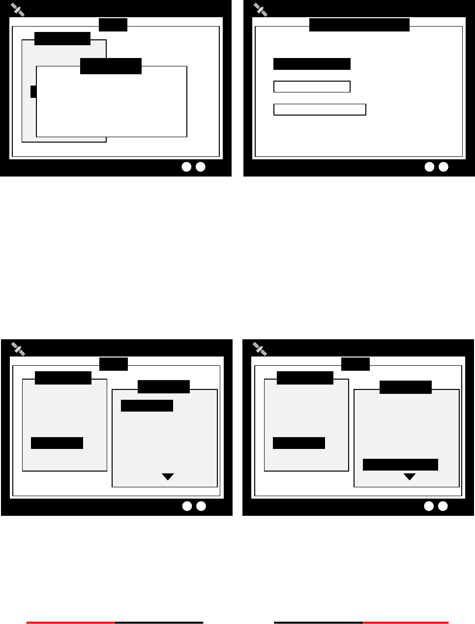
63
4.8 Transceiver
TRANSCEIVER setting sub-menu holds the settings of the transceiver statuses and the supplied voltage for the
GPS antenna.
Figure 80 Transceiver
Pressing MENU or ESC button will ask whether to save data. Select YES to save and exit, or NO to exit without
saving.
Added AIS TX POWER option to configure transmit power, provided with 12.5W and 1W transmit options.
4.9 Sys Config
System configuration provides the preference settings of the device.
Figure 81 System configuration
MENU
MESSAGES
NAV. STATUS
SHIP SETTING
TRANSCEIVER
SYS CONFIG
DIAGNOSTICS
MAIN MENU
SENSOR CONFIG.
FACTORY
PASSWORD
LONG RANGE SET.
LR BCST SET.
DEST. TABLE SET.
SYS CONFIG
2013/01/17 07:18:11
Dangerous Targets :0
MENU
MESSAGES
NAV. STATUS
SHIP SETTING
TRANSCEIVER
SYS CONFIG
DIAGNOSTICS
MAIN MENU
CUSTOMIZE
RADAR VIEW
MAP CALIBRATION
SENSOR CONFIG.
FACTORY
PASSWORD
SYS CONFIG
2013/01/17 07:18:11
Dangerous Targets :0
TRANSCEIVER SETTING
2013/01/17 22:43:39
Targets Received: 10
DSC Rx <ON>
AIS Tx <ON>
GPS ANT. VOLTAGE <3.3V>
MENU
MESSAGES
NAV. STATUS
SHIP SETTING
TRANSCEIVER
SYS CONFIG
DIAGNOSTICS
MAIN MENU
2013/01/17 07:18:11
Dangerous Targets :0
Please enter the password and
hold KNOB for confirmation.
[ **** ]
PASSWORD
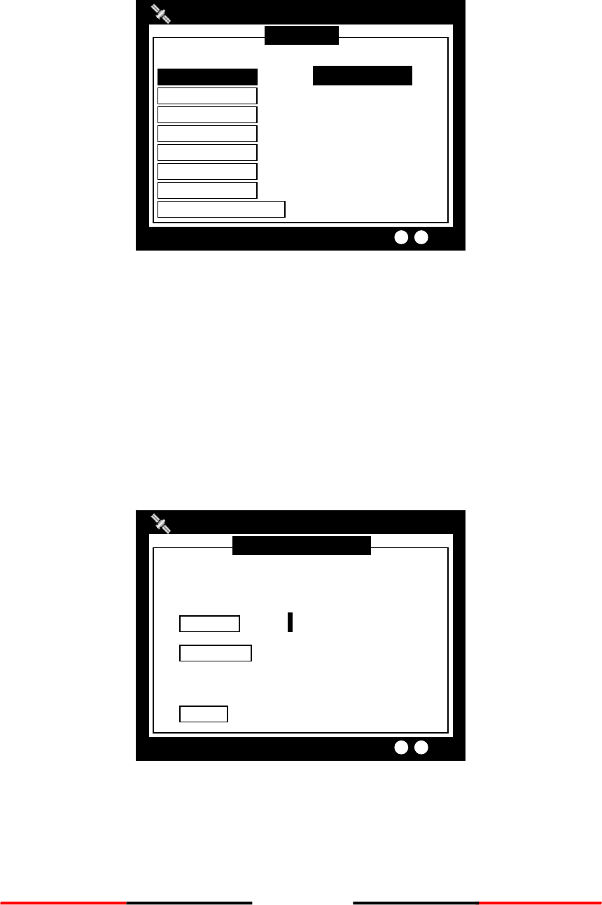
64
4.9.1 Customize
Customize provides personalization settings.
Figure 82 Customize
Pressing MENU or ESC button will ask whether to save data. Select YES to save and exit, or NO to exit without
saving.
4.9.2 Radar View
This setting provides user the ability to center the radar map on given coordinates.
Turn knob to choose either latitude or longitude and press knob to confirm. Once pressed, turn knob to
choose a parameter and press knob again to enter input mode. When finished, press ESC to return to the level
before. Continue these procedures till all settings are set.
Figure 83 Radar View Setting
Pressing MENU or ESC button will ask whether to save data. Select YES to save and exit, or NO to exit without
saving. Added with RADAR VIEW ORIENTATION mode, with NORTH UP/ COURSE UP / HEAD UP.
RADAR VIEW SETTING
2013/01/17 22:43:39
Targets Received: 10
Latitude [53]°[08]’[56]”<N>
Center position of radar view
Longitude [057]°[00]’[00]”<W>
RADAR VIEW ORIENTATION
MODE <NORTH UP>
CUSTOMIZE
2013/01/17 22:43:39
Targets Received: 10
COLOR MODE [Day]
KEY TIME-OUT [1] (1~5 min)
LANGUAGE <English>
ALARM <OFF>
KEY BEEP <None>
DIMMER LEVEL [100] Lo………………………Hi
TIME ZONE <GMT>
SART TEST MODE <OFF>
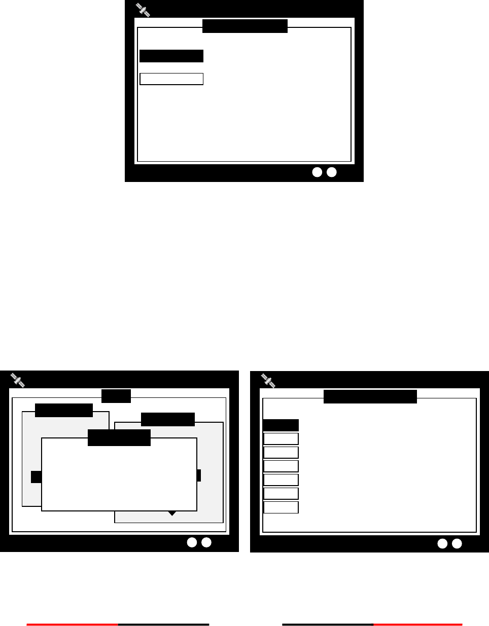
65
4.9.3 Map Calibration
This setting offers user functions to calibrate map data. Turn knob to select either latitude or longitude to
offset. Press knob to enter input mode. Turn knob to select an offset value. Once finished press ESC to return
to the previous level to continue the setting.
Figure 84 Map Calibration
Pressing MENU or ESC button will ask whether to save data. Select YES to save and exit, or NO to exit without
saving.
4.9.4 Sensor Config
Sensor Configuration provides user to set port baud rates. Turn knob to select a port to modify and press
knob to change the specified port baud rate. Turn knob to change the desired rate. When finished, press knob
again to return to the previous level.
Figure 85 Baud Rate Setting
Pressing MENU or ESC button will ask whether to save data. Select YES to save and exit, or NO to exit without
saving.
BAUD RATE SETTING
2013/01/17 22:43:39
DISP <38400>
LR <38400>
DGPS <38400>
SEN 1 <38400>
SEN 2 <38400>
PILOT <38400>
SEN 3 <38400>
MENU
MESSAGES
NAV. STATUS
SHIP SETTING
TRANSCEIVER
SYS CONFIG
DIAGNOSTICS
MAIN MENU
CUSTOMIZE
RADAR VIEW
MAP CALIBRATION
SENSOR CONFIG.
FACTORY
PASSWORD
SYS CONFIG
2013/01/17 07:18:11
Please enter the password and
hold KNOB for confirmation.
[ **** ]
PASSWORD
Dangerous Targets :0
MAP CALIBRATION
2013/01/17 22:43:39
Targets Received: 3
LON OFFSET [+0.000000]
LAT OFFSET [+0.000000]
TX POWER LEVEL: 12.5W
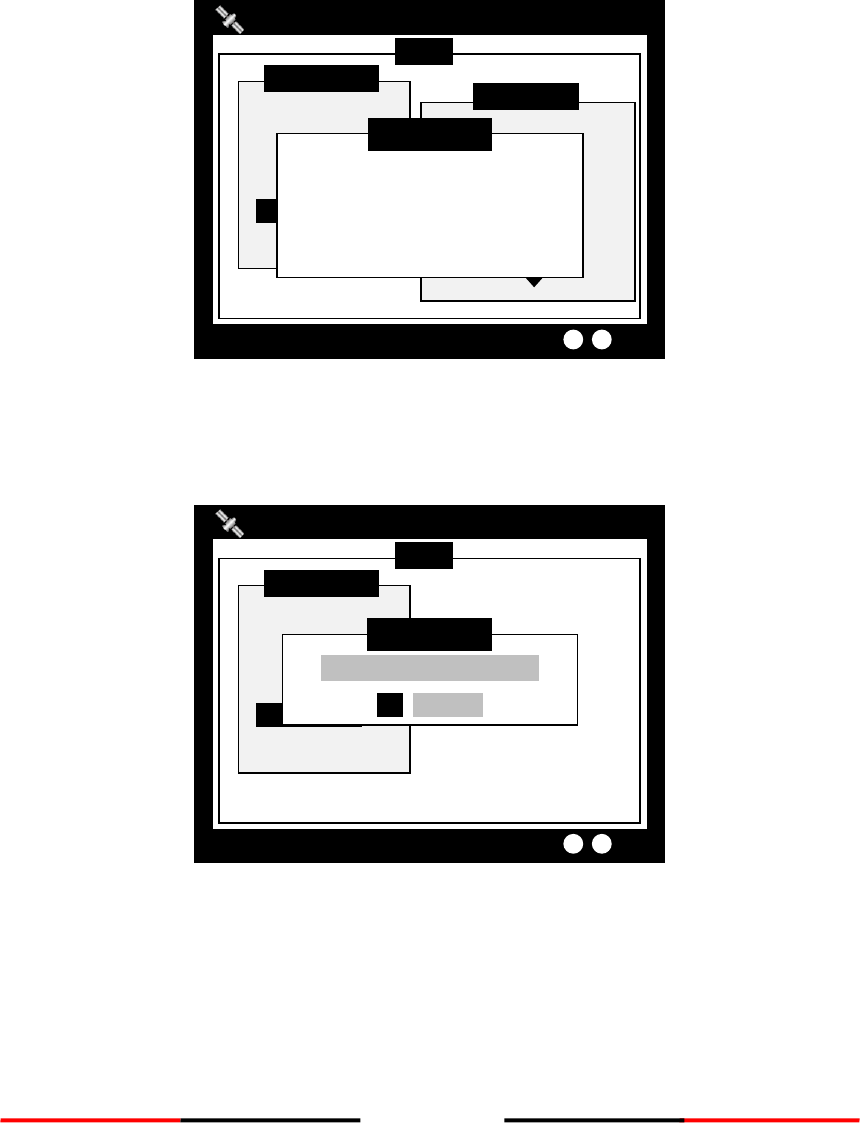
66
4.9.5 Factory
FACTORY option enables user restore default factory setting. It restores system preference settings and
CPA/TCPA values.
Choose a password text location, and then press the knob to enter text input mode. Turn the knob to select a
character, and then press the knob to confirm and to return. Repeat these steps till all desired characters are
entered.
After entering the password, press down the knob for 3 seconds to confirm.
Figure 86 Factory
After entering the password, the system will ask for your confirmation.
Turn knob to choose and press knob to confirm your choice.
Figure 87 Factory Setting
MENU
MESSAGES
NAV. STATUS
SHIP SETTING
TRANSCEIVER
SYS CONFIG
DIAGNOSTICS
MAIN MENU
2013/01/17 07:18:11
Dangerous Targets :0
Restore Factory Setting?
OK CANCEL
WARNING
MENU
MESSAGES
NAV. STATUS
SHIP SETTING
TRANSCEIVER
SYS CONFIG
DIAGNOSTICS
MAIN MENU
CUSTOMIZE
RADAR VIEW
MAP CALIBRATION
SENSOR CONFIG.
FACTORY
PASSWORD
SYS CONFIG
2013/01/17 07:18:11
Dangerous Targets :0
Please enter the password and
hold KNOB for confirmation.
[ **** ]
PASSWORD
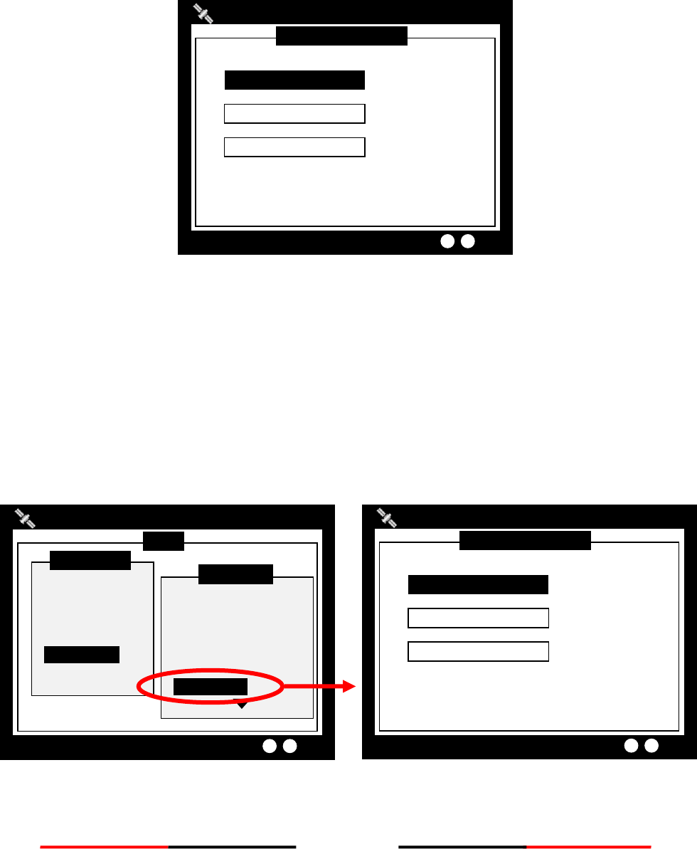
67
4.9.6 Password
This option enables changing user password. (Default password: “0000”)
Set the information with the order of “OLD PASSWORD”, “NEW PASSWORD”, “CONFIRM NEW PASSWORD”.
Turn knob to traverse the items and press knob to enter input mode. Under input mode, turn knob to select
text position and press knob to confirm. Repeat till all four values are entered.
Figure 88 Password
Pressing MENU or ESC button will ask whether to save data. Select YES to save and exit, or NO to exit without
saving.
4.9.6.1 Changing the Password
The password is required in some menu items due to information security. (Default password: “0000”) Please
go to Main MENU item Sys Config and select sub-menu item Password to change it. For password setting,
please refer to 4.5.6 PASSWORD.
Figure 89 Changing Password
PASSWORD SETTING
2013/01/17 07:18:11
Dangerous Targets : 0
NEW Password [ **** ]
Confirm Password [ **** ]
OLD Password [ **** ]
MENU
MESSAGES
NAV. STATUS
SHIP SETTING
TRANSCEIVER
SYS CONFIG
DIAGNOSTICS
MAIN MENU
CUSTOMIZE
RADAR VIEW
MAP CALIBRATION
SENSOR CONFIG
FACTORY
PASSWORD
SYS CONFIG
2013/01/17 07:18:11
Dangerous Targets :0
PASSWORD SETTING
2013/01/17 07:18:11
Dangerous Targets : 0
NEW Password [ **** ]
Confirm Password [ **** ]
OLD Password [ **** ]
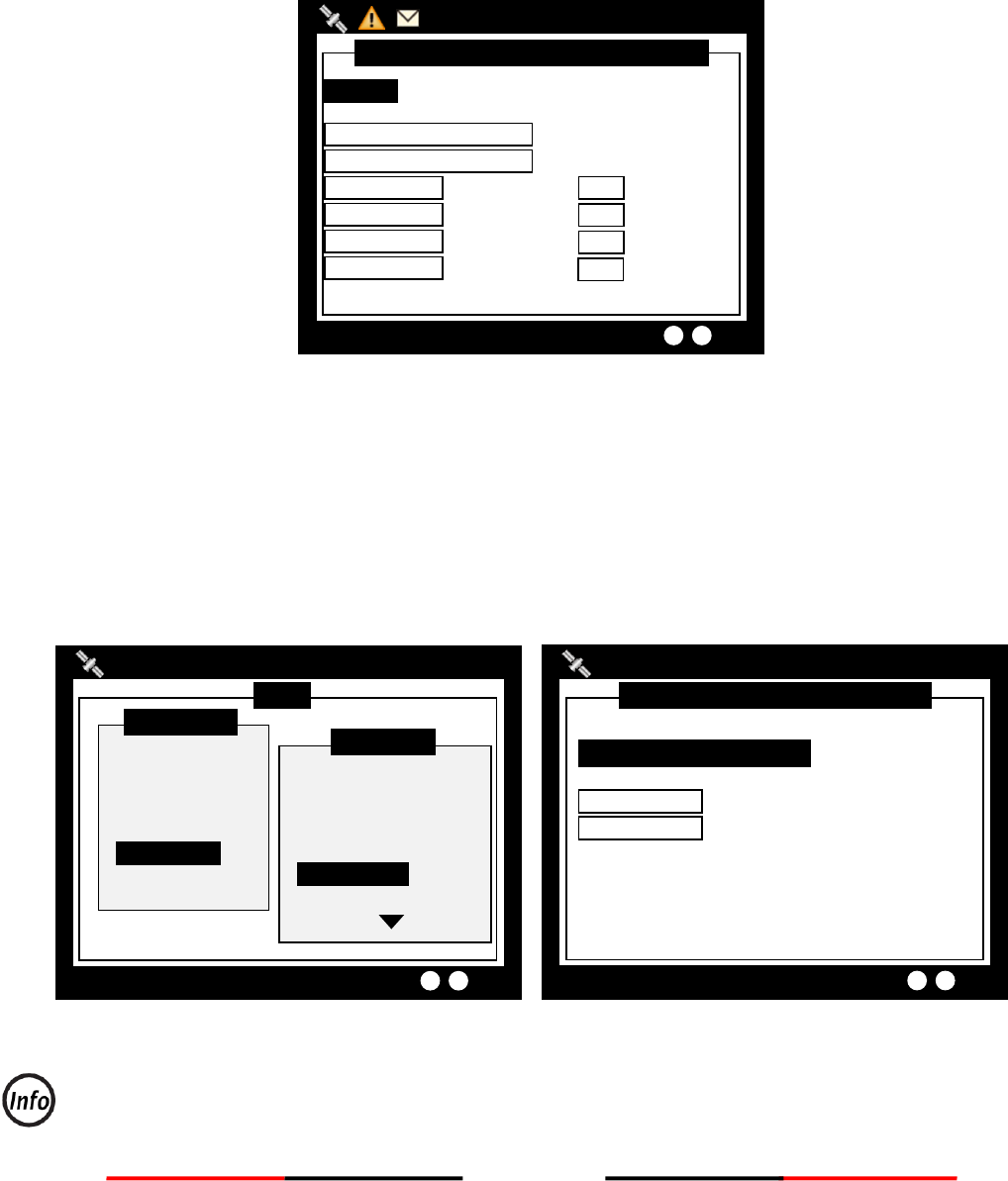
68
4.9.7 Long Range Setting
This option provides user choices to auto-response remote interrogation and settings of the response
information.
You can either set MODE to either AUTO or MANUAL. The setting for the rest of information is either SUPPLY
or REJECT.
Figure 90 Long Range Setting
Pressing MENU or ESC button will ask whether to save data. Select YES to save and exit, or NO to exit without
saving.
4.9.8 Long Range Broadcast
Class A transmits Message 27 every 3 minutes through the channels alternately. Provided here are the
options to enable or disable Long Range Broadcast and the transmitting channel for Message 27.
Figure 91 Long Range Broadcast
Only AIS channel numbers can be entered for TX channel. Channel 2078, 2088, and the current
channel used in the region cannot be used.
LONG RANGE BROADCAST SETTING
2013/01/17 22:43:39
TX POWER LEVEL: 12.5W
TX Channel 1 [0075]
TX Channel 2 [0076]
LONG RANGE BROADCASTFS<ENABLE>
MENU
MESSAGES
NAV. STATUS
SHIP SETTING
TRANSCEIVER
SYS CONFIG
DIAGNOSTICS
MAIN MENU
SENSOR CONFIG.
FACTORY
PASSWORD
LONG RANGE SET.
LR BCST SET.
DEST. TABLE SET.
SYS CONFIG
2013/01/17 07:18:11
Dangerous Targets :0
LONG RANGE INTERROGATION SETTING
2013/01/17 22:43:39
Targets Received: 10
Name, Call,IMO <SUPPLY>
Length, Breadth, Type <SUPPLY>
Date, Time <SUPPLY>
Ship/Cargo <SUPPLY>
Dest. ETA <SUPPLY>
Draught <SUPPLY>
COG <SUPPLY>
POS <SUPPLY>
SOG <SUPPLY>
POB <SUPPLY>
MODE <AUTO>

69
4.9.9 Destination Table Setting
Save up to 10 destinations. Use rotary knob to traverse text and to modify. Press Menu to save changes.
Figure 92 Destination Table Setting
DESTINATION TABLE SETTING
2013/01/17 22:43:39
Dangerous Targets: 0
Column 2 [ ]
Column 3 [ ]
Column 4 [ ]
Column 5 [ ]
Column 6 [ ]
Column 1 [ ]
Column 7 [ ]
Column 8 [ ]
Column 9 [ ]
Column 10 [ ]

70
4.10 Diagnostics
DIAGNOSTICS sub-menu provides users to check system statuses. There are a total of 8 check options.
Figure 93 Diagnostic
4.10.1 System On/Off
This option provides activation history. (when a power-off session is less than 15 minutes, the session would
not be registered in the history)
Figure 94 System On/Off
When finished viewing, press MENU or ESC to exit.
SECURITY EVENT LOG
2013/09/03 16:35:44
Targets Received :67
--- START TIME -------- +END TIME +- STATUS
2012/08/31 09:43 ~ NO RECORD ,N
2012/08/31 10:38 ~ NO RECORD ,N
2012/08/31 10:52 ~ NO RECORD ,N
2012/08/31 10:53 ~ NO RECORD ,N
2012/08/31 11:07 ~ 2012/08/31 12:38 ,P
2012/08/31 14:18 ~ 2012/08/31 14:41 ,P
2012/08/31 16:38 ~ 2012/08/31 10:42 ,P
2012/08/31 16:52 ~ 2012/08/31 18:21 ,P
2012/09/03 13:37 ~ 2012/09/03 14:22 ,P
2012/09/03 14:25 ~ NOW ,N
MENU
MESSAGES
NAV. STATUS
SHIP SETTING
TRANSCEIVER
SYS CONFIG
DIAGNOSTICS
MAIN MENU
KEYBOARD TEST
GPS STATUS
TRANSCEIVER
COMMUN. TEST
PANEL TEST
VERSION
DIAGNOSTICS
2013/01/17 07:18:11
Dangerous Targets :0
MENU
MESSAGES
NAV. STATUS
SHIP SETTING
TRANSCEIVER
SYS CONFIG
DIAGNOSTICS
MAIN MENU
SYSTEM ON/OFF
MEMORY TEST
SENSOR PORT
TFT-PANEL
KEYBOARD TEST
GPS STATUS
DIAGNOSTICS
2013/01/17 07:18:11
Dangerous Targets :0
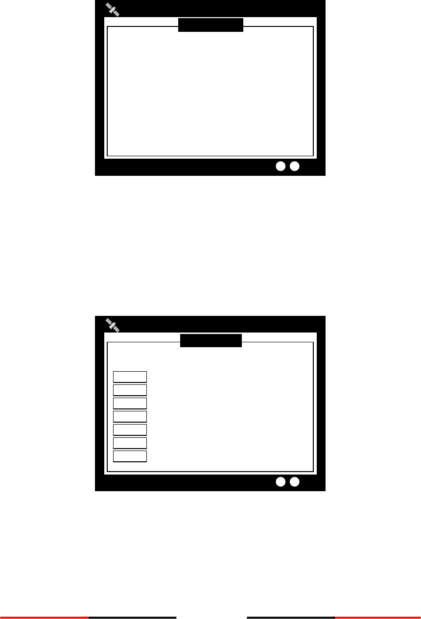
71
4.10.2 Memory Test
This option provides memory testing on the unit.
Figure 95 Memory Test
When finished, press ESC to exit.
4.10.3 Sensor Port
This option provides an overview on all port baud rates and information.
Figure 96 Sensor Port
When finished, press ESC to exit.
SENSOR PORT
2013/01/17 22:43:39
Targets Received: 3
DISP <38400> V V
LR <38400> V V
DGPS <38400> V V
SEN 1 <38400> V --
SEN 2 <38400> V --
PILOT <38400> V V
SEN 3 <38400> V --
Baud Rate RX TX
MEMORY TEST
2013/01/17 22:43:39
Targets Received: 10
Chart Memory [Pass]
System Memory [Pass]
Data Memory
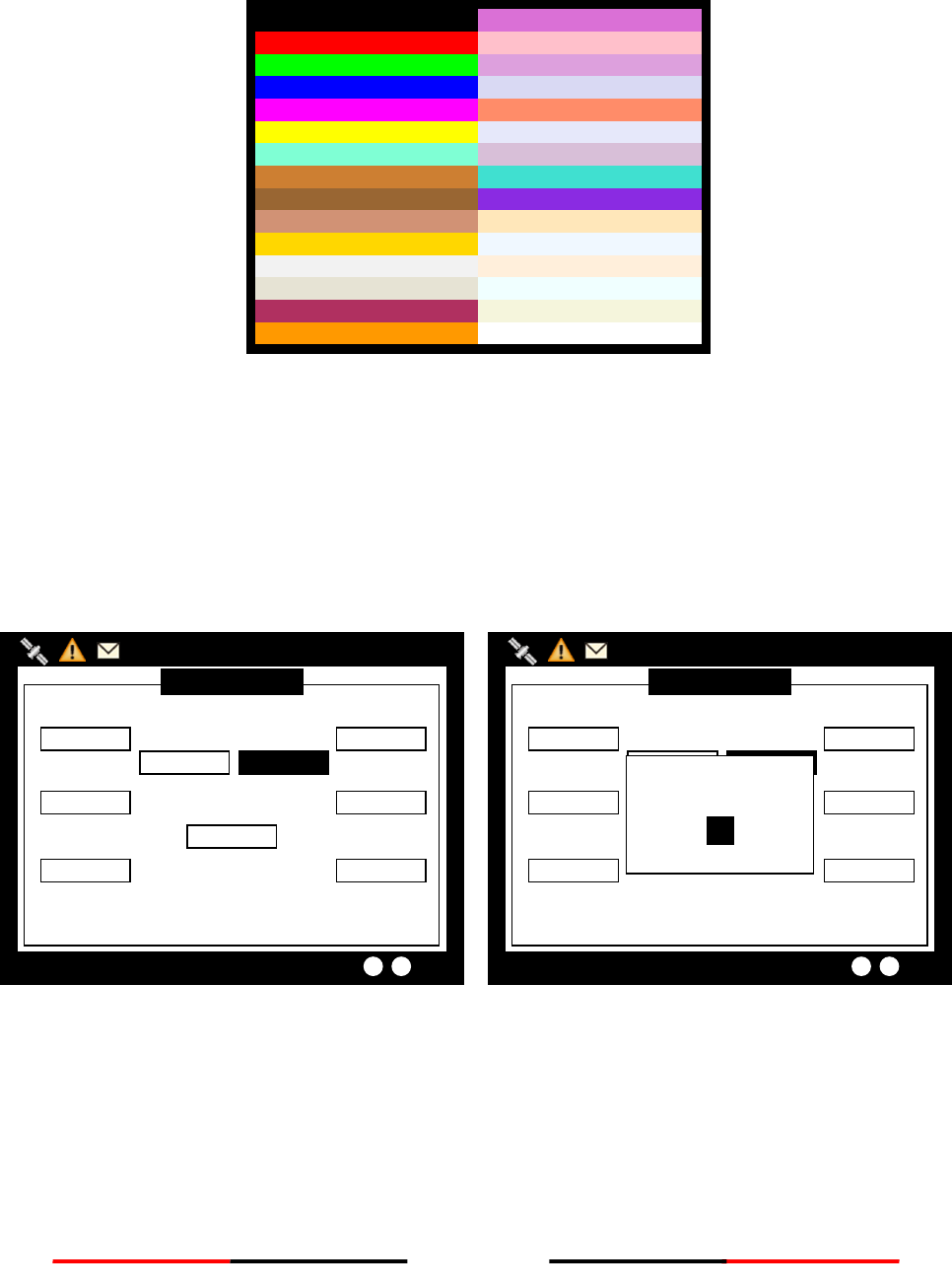
72
4.10.4 TFT-Panel
This option provides color information on the monitor. When finished, press ESC to exit.
Figure 97 TFT-Panel
4.10.5 Keyboard Test
This option provides keyboard testing.
Pressing button during testing, a corresponding button on the screen will response.
Figure 98 Keyboard Test
After all buttons are tested, a message will indicate. Press knob for OK to exit.
To quit test without completing, wait for 30 seconds and the system will return to the main menu.
KEYBOARD TEST
2013/01/17 22:43:39
Dangerous Targets: 2
MENU
LEFT
RIGHT
ESC
USER
DIMMER
ENTER
SRM
DISPLAY
Check Pass
OK
KEYBOARD TEST
2013/01/17 22:43:39
Dangerous Targets: 2
MENU
LEFT
RIGHT
ESC
USER
DIMMER
ENTER
SRM
DISPLAY
Black
Red
Green
Blue
Magenta
Yellow
Aquamarine
Bronze
Copper
Feldspar
Gold
Grey
Khaki
Maroon
Orange
Orchid
Pink
Plum
Quartz
Salmon
Silver
Thistle
Turquoise
Violet
Wheat
Aliceblue
Antiquewhite
Azure
Beige
White
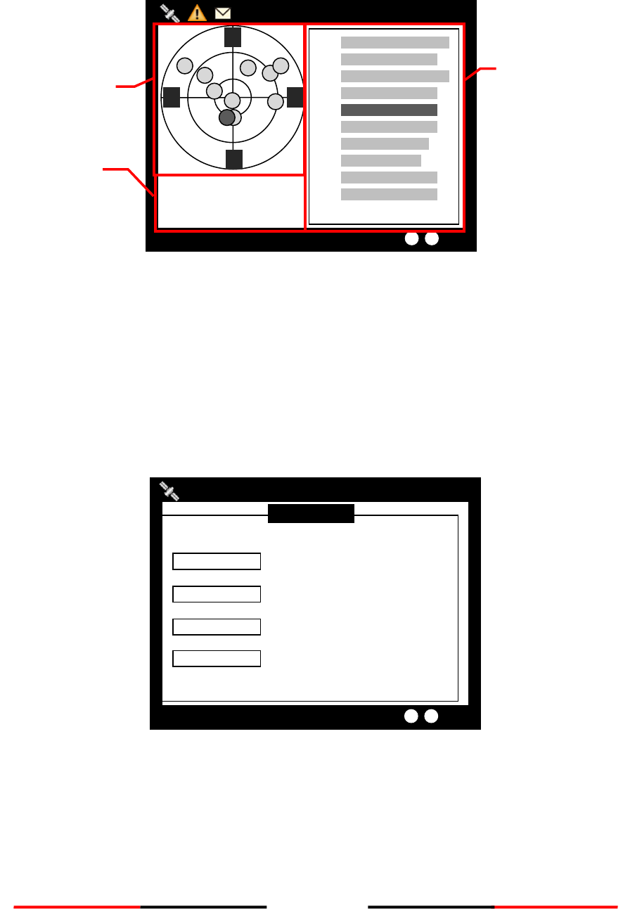
73
4.10.6 GPS Status
This option provides GPS satellite status information.
Figure 99 GPS Status
Green indicates satellite being used for GPS fix.
Red indicates satellite not being used.
4.10.7 Transceiver
The TRANSCEIVER command provides user to view its status. When finished, press ESC to exit.
Figure 100 Transceiver
TRANSCEIVER
2013/01/17 22:43:39
Targets Received: 10
Receiver 1
Transmitter
Receiver 2
DSC Receiver
FREQUENCY STATUS
161.975MHz OK
161.975MHz OK
162.025MHz OK
156.525MHz OK
2013/01/17 22:43:39
Dangerous Targets: 2
53°08’56”N
4°57’00”E
12.00Kn 241.0°
7 41
8 37
19 42
24 40
1 40
11 38
3 34
6 26
16 34
28 34
3
19
28
6
8
E
N
S
W
16
24
1
11
7
Strength of GPS
Satellite Signal
GPS Satellite
location Signal
Own Ship
Information
Signal
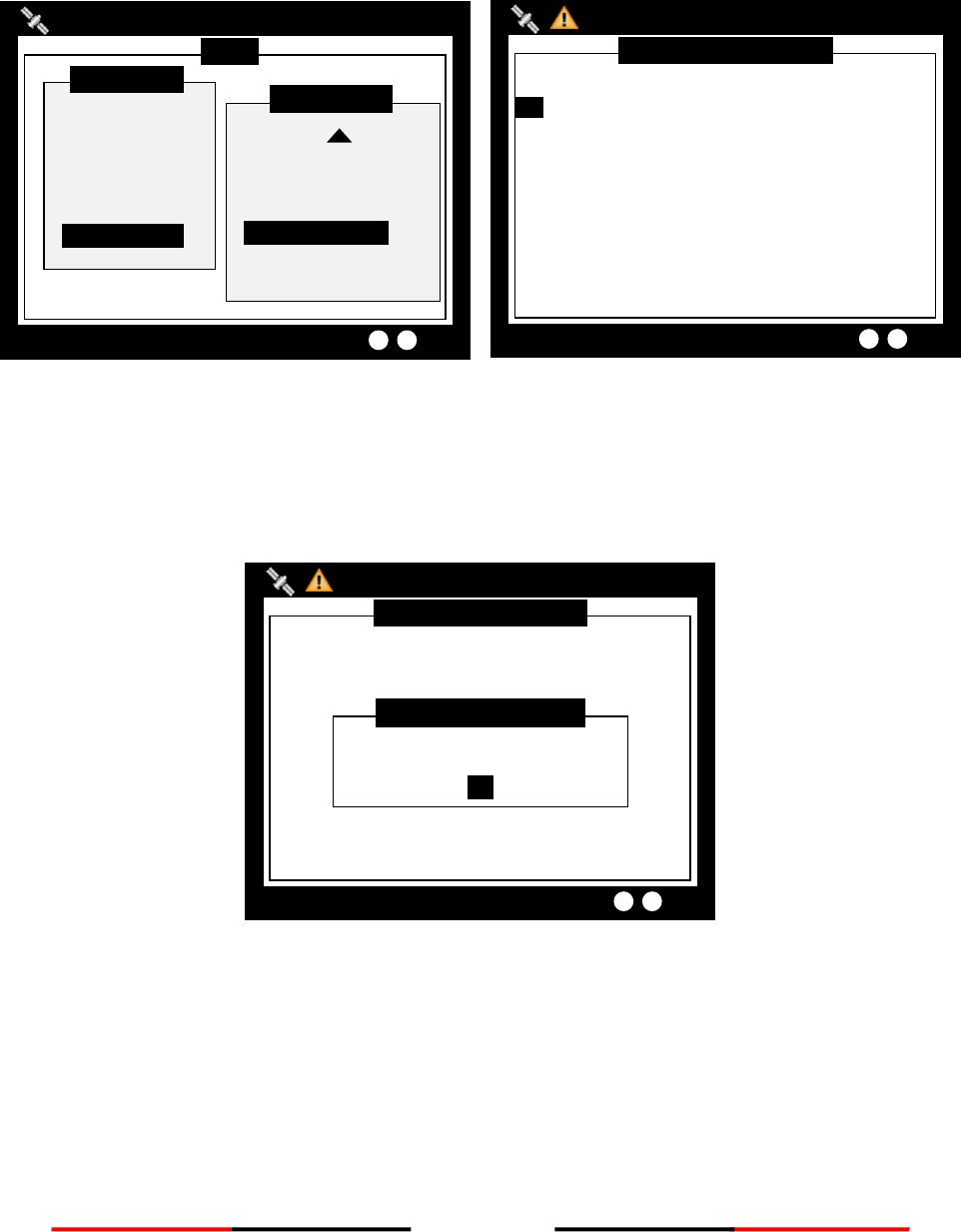
74
4.10.8 Communication Test
Communication can be tested. The procedure starts by having the Class A unit transmits Message 10 to an
addressed Class A MMSI. The target MMSI, once received Message 10, will return Message 11. The test is
complete when the Class A unit successfully receives the Message 11.
Figure 101 Communication Test
Under the communication test page, pressing the MENU button enables the transmission of Message 10. Only
Class A units with GPS fix are listed and eligible for communication testing. If no valid Class A targets found in
range, the screen would show as below.
Figure 102 No Valid Targets
COMMUNICATION TEST
2013/01/17 22:44:22
Targets Received: 10
--- DEST. MMSI ---------- DATE/TIME --- RX ACK
--
NO VALID CLASS A TARGETS
OK
COMM. TEST TARGET
COMMUNICATION TEST
2013/01/17 22:44:22
Targets Received: 10
--- DEST. MMSI ---------- DATE/TIME --- RX ACK
--
1. 233333533 T 09:40 YES
2. 222222222 T 09:40 YES
MENU
MESSAGES
NAV. STATUS
SHIP SETTING
TRANSCEIVER
SYS CONFIG
DIAGNOSTICS
MAIN MENU
KEYBOARD TEST
GPS STATUS
TRANSCEIVER
COMMUN. TEST
PANEL TEST
VERSION
DIAGNOSTICS
2013/01/17 07:18:11
Dangerous Targets :0
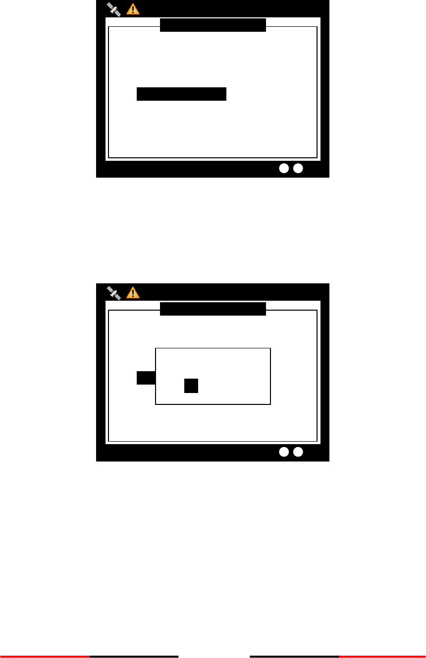
75
As a valid Class A is presence, the test procedure proceeds to the screen below.
Figure 103 Valid Target
After pressing the knob, turn the knob to selected destination MMSI for testing. The destination MMSI
numbers are the nearest Class A targets found close to the Class A unit. Press ESC or MENU to pick selection
and the unit will prompt to confirm message sending. Select OK to proceed testing.
Figure 104 Send Message
COMMUNICATION TEST
2013/01/17 22:44:22
Targets Received: 10
PRESS KNOB TO SELECT
DESTINATION MMSI OF MESSAGE 10
DESTINATION MMSI <233333533>
Send Message?
OK CANCEL
COMMUNICATION TEST
2013/01/17 22:44:22
Targets Received: 10
PRESS KNOB TO SELECT
DESTINATION MMSI OF MESSAGE 10
DESTINATION MMSI <233333533>
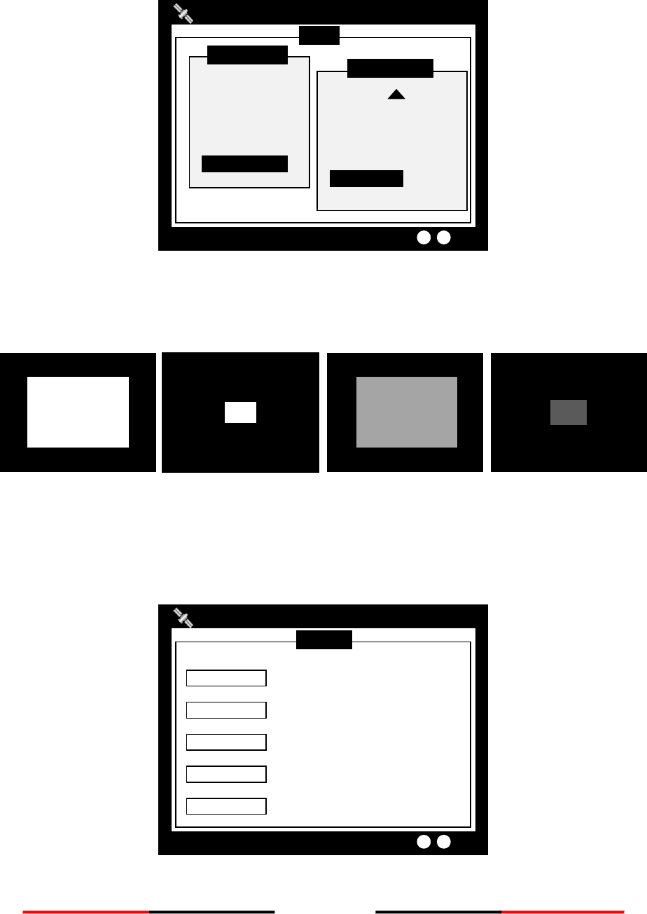
76
4.10.9 Panel Test
Test the brightness of the screen.
Figure 105 Panel Test
In the main function page, select “PANEL TEST”. Press “FUNC” to switch the white cube into different sizes.
Rotate the knob to test in different brightness. To exit the function, press “MENU” or “ESC”.
Figure 106 Test with Size and Brightness
4.10.10 Version
Provide model name, hardware information, firmware version, etc. When finished, press ESC to exit.
Figure 107 Version
VERSION
2013/01/17 22:43:39
Targets Received: 10
FIRMWARE V1.0.6.19
PRODUCT CAMINO-701 AIS Class A
COMPANY Alltek Marine
WEBSITE http://www.alltekmarine.com
S/N A3K7000001
MENU
MESSAGES
NAV. STATUS
SHIP SETTING
TRANSCEIVER
SYS CONFIG
DIAGNOSTICS
MAIN MENU
KEYBOARD TEST
GPS STATUS
TRANSCEIVER
COMMUN. TEST
PANEL TEST
VERSION
DIAGNOSTICS
2013/01/17 07:18:11
Dangerous Targets :0

77
5 TECHNICAL SPECIFICATIONS
5.1 Applicable Standards
IEC 61993-2 Ed. 2, 2012
IEC 62288 Ed. 1.0, 2008
IEC 60945 Ed. 4, 2002
IEC 62388 Ed. 1.0, 2007
IEC 61162-1 Ed. 4, 2010
ITU-R Recommendation M.1084-5
IEC 61162-2 Ed. 1, 1998
ITU-R M.493
IMO MSC.74 (69) Annex 3
ITU-R M.541
ITU-R Recommendation M.1371-4
IEC 61108-1, Ed. 2, 2003
5.2 VHF Transceiver
Frequency Range
156.025 MHz ~ 162.025 MHz
Channel Bandwidth
25 KHz
Modulation
GMSK / FM
Data Rate
9,600 bps
Number of AIS Transmitter
1
Number of AIS Receiver
2
Number of DSC Receiver
1
AIS Channel 1
CH 87B (161.975 MHz)
AIS Channel 2
CH 88B (162.025 MHz)
Tx Power Output
1/12.5 Watt (30/41 dBm ± 1.5 dB)
Rx Sensitivity
< -107 dBm @ 20% PER
5.3 DSC Receiver
Frequency
156.525 MHz
Modulation
FSK
Channel Bandwidth
25K
Sensitivity
< -107 dBm @ BER < 10-2
Spurious Response Rejection
≧ 70 dB for signal @ -104 dBm; BER ≦ 1 %
Blocking
≧ 84 dB for signal @ -104 dBm; BER ≦ 1 %

78
5.4 GPS Receiver (Internal)
Receiving Channels
50 channels
Tracking & Navigation Sensitivity
≧ -159 dBm
Reacquisition Sensitivity
≧ -159 dBm
Horizontal Position
< 2.5 m Autonomous
< 2.0 m SBAS
Receiver Type
SBAS: WAAS, EGNOS,MSAS, GAGAN
5.5 Power Supply
Supply Voltage
12V / 24V DC
Power Consumption
Less than 9W average @ 12V DC;
Less than 65W peak power @ 12V DC
5.6 LCD Display
Screen Size
3.5” color TFT
Pixel Number (Resolution)
320 x 240
Viewing Mode
Basic coastline map/ Radar View/ Alphanumeric views /Satellite View
Dimmer Control
Step-less Setting
5.7 Keypad & Knob
6 Keypads with Back-light
1 for SRM, 1 for Menu, 1 for Dimmer,
1 for ESC, 1 for Display, 1 for Nav. Status
Knob
Multi-Function
5.8 Connection Interface
GPS Antenna Connector
TNC (Female)
VHF Antenna Connector
SO-239 (Female)
Sensor Interfaces 1 to 3
IEC 61162-1 or -2
Pilot / Auxiliary
IEC 61162-2
External Display
IEC 61162-2
Long-range
IEC 61162-2
DGNSS correction input
RTCM-SC-104
Alarm relay
Normally closed

79
USB
Mini type B USB interface
NMEA2000
IEC61162-3
Alarm Output
Relay contact
5.9 Environmental
Operating Conditions
IEC 60945 “protected” category
Operating Temperature
-15°C ~ 55°C
Operating Humidity
95% RH at 40°C
Waterproof
IPX2
5.10 Physical
Width
261 mm (10.28 inch)
Height
184 mm (7.25 inch)
Depth (include connectors)
102 mm (4.02 inch)
Weight
≦2.5 kg
5.11 Pilot Plug
Cable length
2 m
Connector type
Std. Sex 206486-2
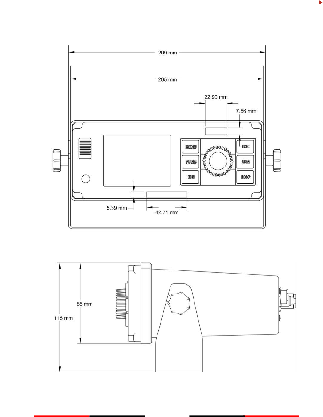
80
6 MECHANICAL DIMENSIONS
6.1 CAMINO-701 Transponder Main Unit
Front (size: mm)
Side (size: mm)
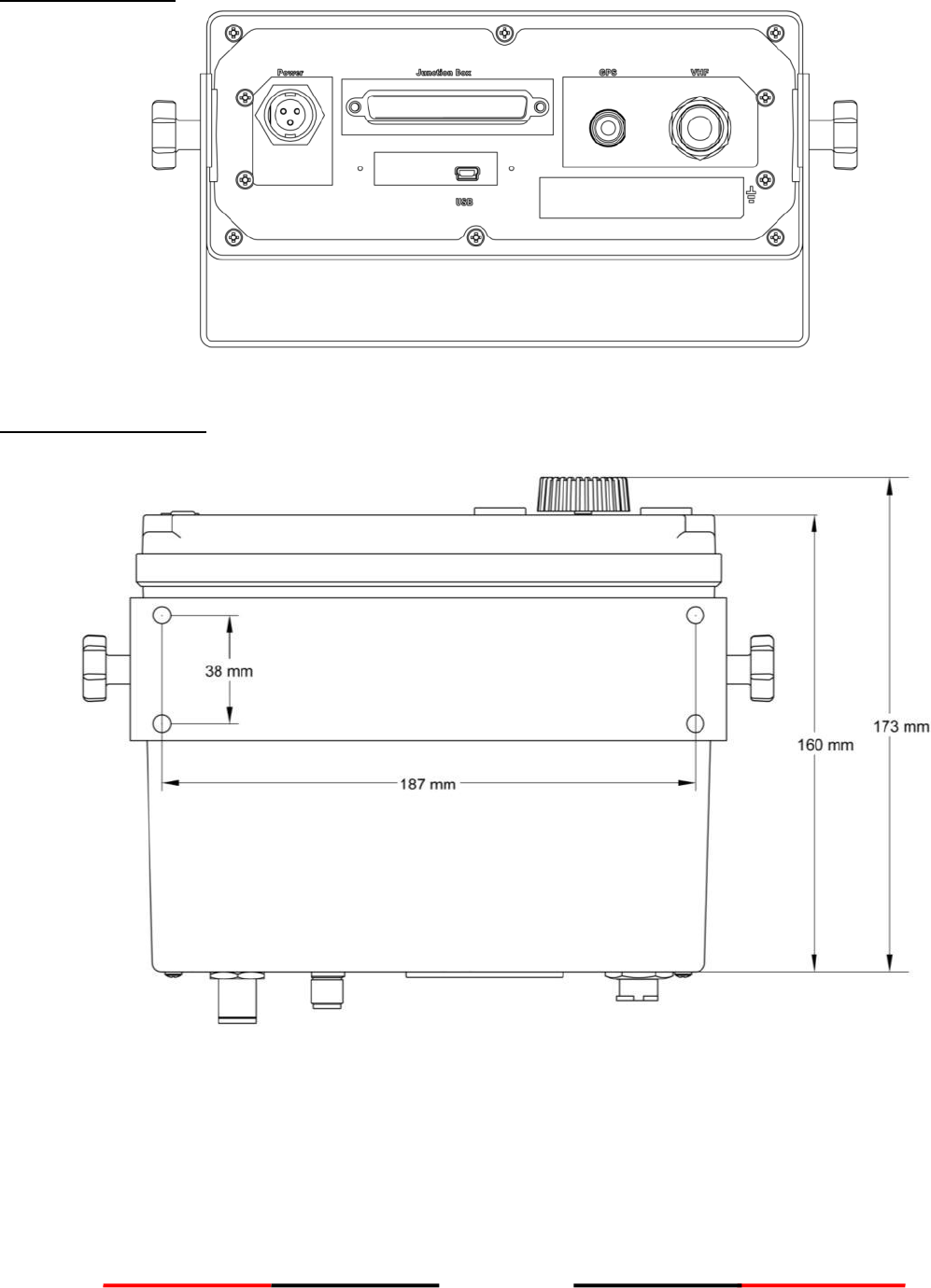
81
Back (size: mm)
Bottom (size: mm)
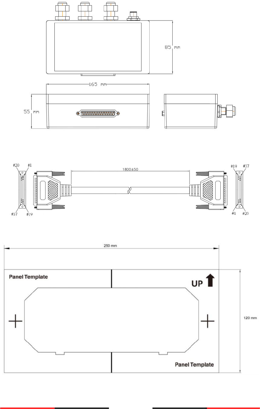
82
6.2 Junction Box
6.3 Extension Cable
6.4 Mounting Template (not to scale)
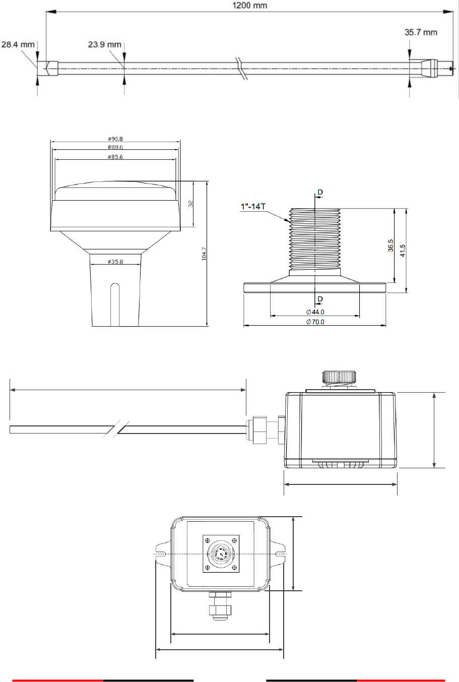
83
6.5 VHF Antenna
6.6 GPS Antenna
6.7 Pilot Plug
2 m
60 mm
40 mm
60 mm
80 mm
103.92 mm

84
7 TROUBLESHOOTING
Use the following guide to perform simple troubleshooting in case the transponder is not function accordingly.
Symptom
Possible Cause
Solution
Transponder cannot power on
Faulty connector to power
Polarity reverse
Power supply current too low
Check power connection
Check power connection
Check power supply
No picture on display
Unit not powered up
Dimmer level set too low
Press power key
Increase Dimmer level
No map detail
Coastline detail not active
Switch to coastline view
No GPS position data
Antenna or cabling problem
Check antenna cable and
connections
No AIS transmission
MMSI not entered
Transmitter disabled
Power supply voltage too low
Enter MMSI number
Enable transmitter
Check power supply
No AIS target
VHF cabling problem
Check antenna cable and
connections
AIS range seems too low
VHF antenna and cabling
Check VHF antenna and
cable installation
Sensor ports not response
Cable installation
Check related wiring
Data port not response
Cable installation
Check related wiring

85
8 ABBREVIATIONS
Terms of abbreviations:
ACK
Acknowledgement
AtoN
Aid to Navigation
AIS
Automatic Identification System
AUTO
Automatic
ALR
Alarm
AUX
Auxiliary
ANT
Antenna
BIIT
Built-In Integrity Test
BRG
Bearing
CH
Channel
CPA
Closest Point of Approach
COG
Course Over Ground
DEST/DESTN
Destination
DISP
Display
DISP
Display
DIST
Distance
DGNSS
Differential GNSS
DSC
Digital Selective Calling
DGPS
Differential GPS
DTE
Data Terminal Equipment
ECDIS
Electronic Chart Display and Information
System
EPIRB
Electronic Position Indicating Radio
Beacon
ECS
Electronic Chart System
ESC
Escape
EGNOS
European Geo-stationary Navigational
Overlay System
ETA
Estimated Time of Arrival
ENC
Electronic Navigation Chart
EXT
External
EPFS
Electronic Position Fixing System
FCC
Federal Communications Commission
FSK
Frequency Shift Keying
FM
Frequency Modulation
FUNC
Function
GAGAN
GPS-aided geo-augmented navigation
GND
Ground
GLONASS
Global Orbiting Navigation and Safety
System
GNSS
Global Navigation Satellite System
GMDSS
Global Maritime Distress and Safety
System
GPS
Global Positioning System
GMSK
Gaussian Minimum Shift Keying
GYRO
Gyro Compass
HDG
Heading
IALA
International Association of Lighthouse
Authorities
IMO
International Maritime Organisation
I/O
Input/Output
IN
Input
ID
Identification
INFO
Information
IEC
International Electotechnical Commission
ITU-R
International Telecommunications
Union - Radio
KN
Knots
LAT
Latitude
LON
Longitude

86
LCD
Liquid Crystal Display
LR
Long Range
MED
Maritime Equipment Directive
MMSI
Maritime Mobile Service Identity
Min
Minute
MOB
Man Overboard
MKD
Minimum Keyboard and Display
MSAS
Multi-functional Satellite
Augmentation System
NAV
Navigation
NMEA
National Marine Electronics
Association
NM
Nautical Mile
OUT
Output
PI
Presentation Interface
RAIM
Receiver Autonomous Integrity
Monitoring
ROT
Rate of Turn
RH
Relative Humidity
RTCM
Radio Technical Commission for
Maritime services
RNG
Range
Rx
Receive / Receiver
S
Second
SOG
Speed Over Ground
SART
Search and Rescue Transponder
SOLAS
Safety of Life at Sea
SAR
Search and Rescue
SRM
Safety Related Message
SBAS
Satellite Based Augmentation System
SYS
System
TCPA
Time to Closest Point of Approach
Tx
Transmit
TDMA
Time Division Multiple Access
Tx / Rx
Transmit / Receive
UHF
Ultra High Frequency
UTC
Universal Time Co-ordinate
USB
Universal Serial Bus
VDL
VHF Data Link
VSWR
Voltage Standing Wave Ratio
VHF
Very High Frequency
WAAS
Wide Area Augmentation System
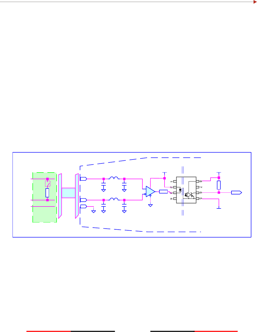
87
APPENDIX (A)
A.1 IEC 61162-2 Data Interface
The CAMINO-701 Class A AIS Transponder provides 2 types of IEC 61162-2 data interfaces for user applications.
The first interface type includes 3 input-only sensor data ports and the second interface type includes 4
bidirectional input/output ports. Data port for each interface type will be described in the following section
below.
A.1.1 Sensor Data Input Ports
The schematic of input-only sensor data port is shown in Figure A1. The schematic includes a standard V.11
transceiver IC (Texas Instruments SN65176B) combined with high speed photocoupler which are used as the
main components to receive external data. The transceiver IC is isolated from external input. To avoid signal
reflection, the transceiver IC has an optional built-in 120Ω loop termination, which is selectable by the dip-
switch on the junction box and the switch should be set to on position when connecting external data source
with long cable. All sensor data-input ports are isolated from one another and are also isolated from internal
power supply. The input impedance on A/B wires is greater than 12 KΩ and the levels on the A/B wires are
defined in the following:
Logic low input: A-B < -0.2V
Logic high input: A-B > +0.2V
1K
3V3
System Ground
Isolated Ground
1K
A
B
TGND TGND
120
A
B
TGND
Junction Box
Cable Rx
Isolated
Main Unit
To
system
Data
Input
V5T
Figure A1 Schematic of sensor data input port.
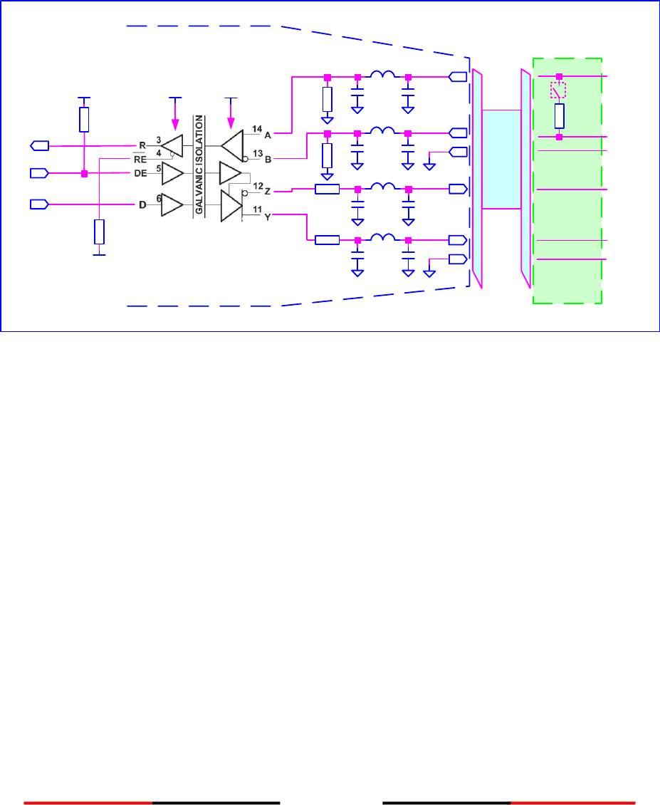
88
A.1.2 Bidirectional Data Ports
The schematic of bidirectional data port is shown in Figure A2. The schematics inscludes an isoltated full
duplex RS-485 transceiver IC (Texas Instrument ISO3080) which is used as the main component to handle both
data input and output from external data source. The transceiver IC is isolated from external input. To avoid
signal reflection, the transceiver IC has an optional built-in 120Ω loop termination, which is selectable by the
dip-switch on the junction box and the switch should be set to on position when connecting external data
source with long cable. All bidirectional data ports are isolated from one another and are also isolated from
internal power supply. The transceiver internal power supply is fully isolated from the external power supply.
3V3 V5T
3V3
Cable 120
RX_A
TGND
Junction Box
Data
Input
RX_B
TX_B
TX_A
TGND
Data
Output
System Ground
Rx
Tx
To/From
System
Isolated
Isolated Ground
10
10
100K
100K
Main Unit
10K
DE
RX_A
RX_B
TX_B
TX_A
ISO3080
TGND
TGND
TGND
Figure A2 Schematic of bidirectional data port.
The output driver capability of bidirectional data port can provide a maximum of 60mA, and the minimum
differential output swing under 100 Ω load can be 2.3V.
A.1.3 A and B Signal Lines
Refer to sections A.1.1 and A.1.2.
A.1.4 Output Driver
The output driver capability of bi-direction data port can provide maximum 60mA, and the minimum
differential output swing under 100 ohm load can be 2.3V.
A.1.5 Input Load
Refer to sections A.1.1 and A.1.2.
A.1.6 Hardware Input/Output Circuit
Refer to sections A.1.1 and A.1.2.
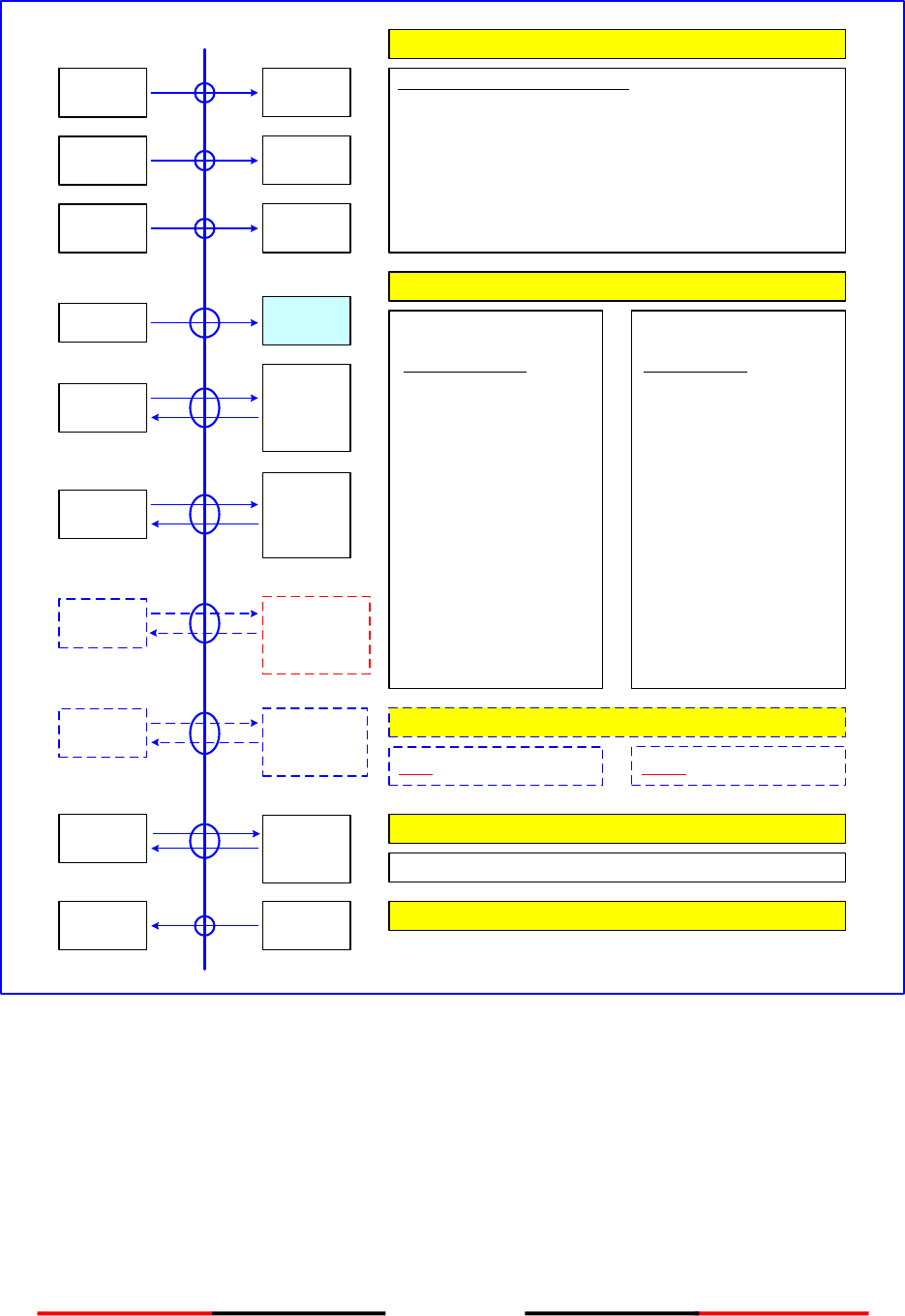
89
A.2 Presentation Interface of CAMINO-701
CH1
PI Port No.
61162-1
61162-2
CH2 61162-1
61162-2
CH3 61162-1
61162-2
Minimum required input sentences:
Position
SOG
COG
Heading
Rotaion rate
RAIM
GNS, GLL, RMC
RMC,VBW, VTG
RMC, VBW, VTG
HDT
ROT
GBS
int/ext *
int/ext *
int/ext *
ext
ext
ext
* for priority refer to IEC 61993-2
Sensor Inputs
CH4
External
display
61162-2
CH5
CH6
Pilot port
61162-2
Input / Output of AIS Data
optional
61162-3
(NMEA2000)
INPUT
Manual Data Input
Voyage
VSD
Static
SSD
VDL messages:
ABM
BBM
AIR Interrogation
Others:
ACA Channel ass.
ACK Alarm ack.
PAMC Proprietary
OUTPUT
VDL messages:
VDM
(Data block of VDM
representing binary Data
contents of VDL messages)
Others:
VDO Own ship data
ALR Alarm status
ABK VDL ack
TXT sensors status
ACA channel
management
information
PAMC Proprietary
Long Range Port (optional)
Input LRI,LRF Output LRF, LR1,2,3
DGNSS Data Port
Correction data information (optional)
BIIT Output Port
Long range
61162-2
DGNSS
Data
823-2
BIIT
NC Relay
CH8
CH9
CH10
CH11 Blue sign
(optional)
Figure A3 Presentation Interface of CAMINO-701
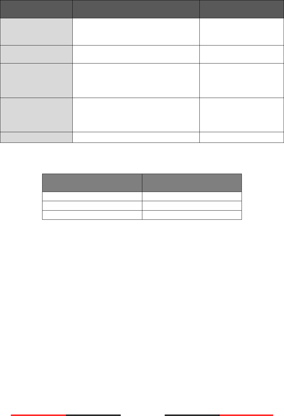
90
A.3 Supported IEC 61162 Data Sentences
Data Port
Input Sentences
Output Sentences
Sensor 1
Sensor 2
Sensor 3
DTM, GNS, RMC, VBW, HDT, HDG, ROT,
GBS, GLL, VTG, THS, GSA
N/A
DGPS
DTM, GNS, RMC, VBW, HDT, HDG, ROT,
GBS, GLL, VTG, THS, GSA
N/A
External Display
ABM, ACA, ACK, AIR, BBM, SSD,
VSD, AIQ, LRI, LRF, SPW, EPV
ABK, ACA, VDM, VDO,
TXT, ALR, LRF, LR1, LR2,
LR3, EPV
Pilot
ABM, ACA, ACK, AIR, BBM, SSD,
VSD, AIQ, LRI, LRF, SPW, EPV
ABK, ACA, VDM, VDO,
TXT, ALR, LRF, LR1, LR2,
LR3, EPV
Long Range
LRI, LRF
LRF, LR1, LR2, LR3
A.4 Transmission Interval
Sentence
Interval
VDO
Once a second
ALR (active)
Once every thirty seconds
ALR (inactive)
Once every sixty seconds

91
A.5 Interpretation of Input Sentences
A.5.1 ABM – AIS Addressed Binary and Safety Related Message
This sentence supports ITU-R M.1371 Messages 6, 12, 25, 26 and provides an external application
with a means to exchange data via an AIS transponder.
A.5.2 ACA – AIS Channel Assignment Message
An AIS device can receive regional channel management information.
$--ACA,x,llll.ll,a,yyyyy.yy,a,llll.ll,a,yyyyy.yy,a,x,xxxx,x,xxxx,x,x,x,a,x,hhmmss.ss*hh<CR><LF>
Field No.
Format
Description
Remark
1
x
Sequence Number
2
llll.ll,a
Region northeast corner latitude – N/S
3
yyyyy.yy,a
Region northeast corner longitude – E/W
4
llll.ll,a
Region southwest corner latitude – N/S
5
yyyyy.yy,a
Region southwest corner longitude – E/W
6
x
Transition zone size
7
xxxx
Channel A
8
x
Channel A bandwidth
9
xxxx
Channel B
10
x
Channel B bandwidth
11
x
Tx/Rx mode control
12
x
Power level control
13
a
Information source
14
x
In-use flag
15
hhmmss.ss
Time of “in use” change
!--ABM,x,x,x,xxxxxxxxx,x,xx,s—s,x*hh<CR><LF>
Field No.
Format
Description
Remark
1
x
Total number of sentences needed to transfer the message
2
x
Sentence number
3
x
Sequential message identifier
4
xxxxxxxxx
The MMSI of the destination AIS unit for the ITU-R M.1371
message
5
x
AIS channel for broadcast of the radio message
6
xx
ITU-R M.1371 message ID
7
s—s
Encapsulated data
8
x
Number of fill-bits

92
A.5.3 ACK – Acknowledge Alarm
This sentence is used to acknowledge an alarm condition reported by a device.
$--ACK,xxx*hh<CR><LF>
Field No.
Format
Description
Remark
1
xxx
Unique alarm number (identifier) at alarm source
A.5.4 AIQ - Query Sentence
This sentence is used to inquire AIS sentence information.
$--AIQ,c—c*hh<CR><LF>
Field No.
Format
Description
Remark
1
c—c
Support query sentence of ACA, EPV, SSD, VSD, TXT.
A.5.5 AIR – AIS Interrogation Request
This sentence supports ITU-R M.1371 messages 15 and 10. It provides an external application with
the means to initiate requests for specific ITU-R M.1371 messages from AIS unit.
$--AIR,xxxxxxxxx,x.x,x,x.x,x,xxxxxxxxx,x.x,x*hh<CR><LF>
Field No.
Format
Description
Remark
1
xxxxxxxxx
MMSI of interrogated station 1
2
x.x
ITU-R M.1371 message requested from station-1
3
x
Message sub-section
ignored
4
x.x
Number of second message requested from station-
1
5
x
Message sub-section
ignored
6
xxxxxxxxx
MMSI of interrogated station-2
7
x.x
Number of messages requested from station-2
8
x
Message sub-section
ignored
A.5.6 BBM – AIS Broadcast Binary Message
This sentence supports generation of ITU-R M.1371 binary messages 8, 14, 25, and 26. This provides
the application with a means to broadcast data, as defined by the application only.
!--BBM,x,x,x,x,x.x,s—s,x*hh<CR><LF>
Field No.
Format
Description
Remark
1
x
Total number of sentences needed to transfer the message
2
x
Sentence number
3
x
Sequential message identifier
4
x
AIS channel for broadcast of the radio message
5
x.x
ITU-R M.1371 Message ID
6
s—s
Encapsulated data
7
x
Number of fill-bits

93
A.5.7 DTM – Datum Reference
Local geodetic datum and datum offsets from a reference datum.
$--DTM,ccc,a,x.x,a,x.x,a, x.x,ccc*hh<CR><LF>
Field No.
Format
Description
Remark
1
ccc
Local datum
2
a
Local datum subdivision code
ignored
3
x.x, a
Lat offset, min, N/S
ignored
4
x.x, a
Lon offset, min, E/W
ignored
5
x.x
Altitude offset, m
ignored
6
ccc
Reference datum
A.5.8 EPV – Command or Report Equipment Property Value
$--EPV,a,cc,c--c,x.x,c--c*hh<CR><LF>
Field No.
Format
Description
Remark
1
a
Sentence status flag
2
cc
Destination equipment type
3
c--c
Unique identifier
4
x.x
Property identifier
5
c--c
Value of property to be set
A.5.9 GBS – GNSS Satellite Fault Detection
This sentence is used to support receiver autonomous integrity monitoring (RAIM).
$--GBS, hhmmss.ss, x.x, x.x, x.x, xx, x.x, x.x, x.x *hh <CR><LF>
Field No.
Format
Description
Remark
1
hhmmss.ss
UTC time of the GGA or GNS fix associated with
this sentence
2
x.x
Expected error in latitude
3
x.x
Expected error in longitude
4
x.x
Expected error in altitude
ignored
5
xx
ID number of most likely failed satellite
ignored
6
x.x
Probability of missed detection for most likely
failed satellite
ignored
7
x.x
Estimate of bias on most likely failed satellite
ignored
8
x.x
Standard deviation of bias estimate
ignored

94
A.5.10 GLL – Geographic Position – Latitude/Longitude
Latitude and longitude of vessel position, time of position fix and status.
$--GLL, llll.ll, a, yyyyy.yy, a, hhmmss.ss, A, a *hh<CR><LF>
Field No.
Format
Description
Remark
1
llll.ll, a
Latitude, N/S
2
yyyyy.yy, a
Longitude, E/W
3
hhmmss.ss
UTC of position
4
A
Status, A=data valid V=data invalid
5
a
Mode indicator
A.5.11 GNS – GNSS Fix Data
Fix data for single or combined satellite navigation systems (GNSS). This sentence provides fix data for
GPS, GLONASS, possible future satellite systems and systems combining these.
$-- GNS, hhmmss.ss, llll.ll, a, yyyyy.yy, a, c--c,xx,x.x,x.x,x.x,x.x,x.x,a *hh<CR><LF>
Field No.
Format
Description
Remark
1
hhmmss.ss
UTC of position
2
llll.ll, a
Latitude, N/S
3
yyyyy.yy, a
Longitude, E/W
4
c--c
Mode indicator
5
xx
Total number of satellites in use
ignored
6
x.x
HDOP
ignored
7
x.x
Antenna altitude, m, re:mean-sea-level (geoid)
ignored
8
x.x
Geoidal separation, m
ignored
9
x.x
Age of differential data
ignored
10
x.x
Differential reference station ID
ignored
11
a
Nacigational status indicator
A.5.12 GSA – GNSS DOP and Active Satellites
GNSS receiver operating mode, satellites used in the navigation solution reported by the GGA or GNS
sentences, and DOP values. If only GPS, GLONASS, etc. are used for the reported position solution,
the talker ID is GP, GL, etc. and the DOP values pertain to the individual system.
$--GSA, a, x, xx,xx,xx,xx,xx,xx,xx,xx,xx,xx,xx,xx,x.x,x.x,x.x*hh<CR><LF>
Field No.
Format
Description
Remark
1
a
Mode:
M = manual, forced to operate in 2D or 3D mode
A = automatic, allowed to automatically switch 2D/3D
2
x
Mode: 1 = fix not available, 2 = 2D, 3 = 3D
3
xx,xx,xx,xx,xx,xx,
xx,xx,xx,xx,xx,xx
ID numbers of satellites used in solution
4
x.x
PDOP
5
x.x
HDOP
6
x.x
VDOP

95
A.5.13 HDG – Heading, Deviation and Variation
Heading (magnetic sensor reading), which if corrected for deviation will produce magnetic
heading, which if offset by variation will provide true heading.
$--HDG, x.x, x.x, a, x.x, a*hh<CR><LF>
Field No.
Format
Description
Remark
1
x.x
Magnetic sensor heading, degrees
2
x.x,a
Magnetic deviation, degrees E/W
3
x.x,a
Magnetic variation,degrees E/W
A.5.14 HDT – Heading True
Actual vessel heading in degrees true produced by any device or system producing true
heading.
$--HDT, x.x, T*hh<CR><LF>
Field No.
Format
Description
Remark
1
x.x, T
Heading, degrees true
A.5.15 LRF – AIS Long-Range Function
This sentence is used in both long-range interrogation requests and long-range interrogation replies.
The LRF-sentence is the second sentence of the long-range interrogation request pair, LRI and LRF
(see the LRI-sentence).
$--LRF,x,xxxxxxxxx,c—c,c—c,c—c*hh<CR><LF>
Field No.
Format
Description
Remark
1
x
Sequence number
2
xxxxxxxxx
MMSI of requestor
3
c—c
Name of requestor
4
c—c
Function request
5
c—c
Function reply status
A.5.16 LRI – AIS Long-Range Interrogation
The long-range interrogation of the AIS unit is accomplished through the use of two sentences. The
pair of interrogation sentence formatters, a LRI sentence followed by a LRF sentence, provides the
information needed by a universal AIS unit to determine if it should construct and provide the reply
sentences (LRF, LR1, LR2, and LR3).
$--LRI,x,a,xxxxxxxxx,xxxxxxxxx,llll.ll,a,yyyyy.yy,a,llll.ll,a,yyyyy.yy,a*hh<CR><LF>
Field No.
Format
Description
Remark
1
x
Sequence number
2
a
Control flag
3
xxxxxxxxx
MMSI of requestor
4
xxxxxxxxx
MMSI of destination
5
llll.ll,a
Latitude – N/S
6
yyyyy.yy,a
Longitude – E/W
7
llll.ll,a
Latitude – N/S

96
8
yyyyy.yy,a
Longitude – E/W
A.5.17 RMC – Recommended Minimum Specific GNSS Data
Time, date, position, course and speed data provided by a GNSS navigation receiver.
$--RMC, hhmmss.ss, A, llll.ll,a, yyyyy.yy, a, x.x, x.x, xxxxxx, x.x,a, a, a*hh<CR><LF>
Field No.
Format
Description
Remark
1
hhmmss.ss
UTC of position fix
2
A
Status
3
llll.ll,a
Latitude, N/S
4
yyyyy.yy, a
Longitude, E/W
5
x.x
Speed over ground, knots
6
x.x
Course over ground, degrees true
7
xxxxxx
Date: dd/mm/yy
8
x.x,a
Magnetic variation, degrees, E/W
9
a
Mode indicator
10
a
Navigational status
A.5.18 ROT – Rate of Turn
Rate of turn and direction of turn.
$--ROT, x.x, A*hh<CR><LF>
Field No.
Format
Description
Remark
1
x.x
Rate of turn, °/min
2
A
Status: A = data valid, V = data invalid
A.5.19 SPW - Security Password Sentence
This sentence can be used for authentication. For this purpose the sentence has to be applied before
the protected sentence (for example EPV, SSD).
$--SPW,ccc,c--c,x,c--c*hh<CR><LF>
Field No.
Format
Description
Remark
1
ccc
Password protected sentence
2
c--c
Unique Identifier
3
x
Password level
4
c--c
Password
A.5.20 SSD – AIS Ship Static Data
This sentence is used to enter static parameters into a shipboard AIS unit. The parameters in this
sentence support a number of the ITU-R M.1371 Messages.
$--SSD,c—c,c—c,xxx,xxx,xx,xx,c,aa*hh<CR><LF>
Field No.
Format
Description
Remark
1
c—c
Ship’s call sign
2
c—c
Ship’s name
3
xxx
Pos. ref., point dist.“A,”

97
4
xxx
Pos. ref.,point dist. “B,”
5
xx
Pos. ref., point dist.“C,”
6
xx
Pos. ref.,point dist. “D,”
7
c
DTE indicator flag
8
aa
Source identifier
A.5.21 THS – True Heading and Status
Actual vessel heading in degrees true produced by any device or system producing true
heading. This sentence includes a “mode indicator” field providing critical safety related
information about the heading data, and replaces the deprecated HDT sentence.
$--THS,x.x,a*hh<CR><LF>
Field No.
Format
Description
Remark
1
x.x
Heading, degrees true
2
a
Mode indicator
A.5.22 VBW – Dual Ground/Water Speed
Water-referenced and ground-referenced speed data.
$--VBW, x.x, x.x, A, x.x, x.x, A, x.x, A, x.x, A*hh<CR><LF>
Field No.
Format
Description
Remark
1
x.x
Longitudinal water speed, knots
ignored
2
x.x
Transverse water speed , knots
ignored
3
A
Status : water speed, A = data valid, V = data invalid
ignored
4
x.x
Longitudinal ground speed , knots
5
x.x
Transverse ground speed , knots
6
A
Status , ground speed, A = data valid, V = data invalid
7
x.x
Stern transverse water speed , knots
ignored
8
A
Status : stern water speed,A = data valid, V = data invalid
ignored
9
x.x
Stern transverse ground speed ,knots
ignored
10
A
Status : stern ground speed,A = data valid, V = data invalid
ignored
A.5.23 VSD – AIS Voyage Static Data
This sentence is used to enter information about a ship’s transit that remains relatively static during
the voyage.
$--VSD,x.x,x.x,x.x,c—c,hhmmss.ss,xx,xx,x.x,x.x*hh<CR><LF>
Field No.
Format
Description
Remark
1
x.x
Type of ship and cargo category
2
x.x
Maximum present static draught
3
x.x
Persons on-board
4
c—c
Destination
5
hhmmss.ss
Estimated UTC of arrival at destination
6
xx
Estimated day of arrival at destination
7
xx
Estimated month of arrival at destination
8
x.x
Navigational status

98
9
x.x
Regional application flags
A.5.24 VTG – Course Over Ground and Ground Speed
The actual course and speed relative to the ground.
$--VTG, x.x, T, x.x, M, x.x, N, x.x, K,a*hh<CR><LF>
Field No.
Format
Description
Remark
1
x.x, T
Course over ground, degrees true
2
x.x, M
Course over ground, degrees magnetic
ignored
3
x.x, N
Speed over ground, knots
4
x.x, K
Speed over ground, km/h
ignored
5
a
Mode indicator
A.5.25 PAMC, DBG – Proprietary Sentences, Debug
The proprietary sentences are additional sentences only applicable to this product. Its main usage is
for enabling testing mode and parameter settings.
This sentence is used for configuration. It commands unit with given parameters.
$PAMC,C,c-c,x,x,x,x,x,x,x,x*hh<CR><LF>
Field No.
Format
Description
remark
1
C
Command : “C”
2
c-c
Function type. For example, DBG.
3
x
Parameter Id 1 , 0-998
4
x
Parameter value 1 , 0- 1000000000
5
x
Parameter Id 2 , 0-998
6
x
Parameter value 2, 0- 1000000000
7
x
Parameter Id 3 , 0-998
8
x
Parameter value 3, 0- 1000000000
7
x
Parameter Id 4 , 0-998
8
x
Parameter value 4, 0- 1000000000
This sentence is used for retrieving responses.
$PAMC,R,c-c,x,x,x,x,x,x,x,x*hh<CR><LF>
Field No.
Format
Description
Remark
1
R
Response : “R”
2
c-c
Function type. For example, DBG.
3
x
Parameter Id 1 , 0-998
4
x
Parameter value 1 , 0- 1000000000
5
x
Parameter Id 2 , 0-998
6
x
Parameter value 2, 0- 1000000000
7
x
Parameter Id 3 , 0-998
8
x
Parameter value 3, 0- 1000000000

99
7
x
Parameter Id 4 , 0-998
8
x
Parameter value 4, 0- 1000000000
A.5.26 PAMC, DSC – Proprietary Sentences, Digital selective calling
When AIS transponder receives DCS messages, this sentence is used to output DSC pattern.
$PAMC,R,DSC,c-c*hh<CR><LF>
Field No.
Format
Description
Remark
1
c-c
DSC pattern
A.6 Interpretation of Output Sentences
A.6.1 ABK – AIS Addressed and Binary Broadcast Acknowledgement
The ABK-sentence is generated when a transaction, initiated by reception of an ABM, AIR, or BBM
sentence, is completed or terminated.
$--ABK,xxxxxxxxx,x,x.x,x,x*hh<CR><LF>
Field No.
Format
Description
Remark
1
xxxxxxxxx
MMSI of the addressed AIS unit
2
x
AIS channel of reception
3
x.x
ITU-R M.1371Message ID
4
x
Message sequence number
5
x
Type of acknowledgement
A.6.2 ACA – AIS Channel Assignment Message
An AIS device can receive regional channel management information
$-ACA,x,llll.ll,a,yyyyy.yy,a,llll.ll,a,yyyyy.yy,a,x,xxxx,x,xxxx,x,x,x,a,x,hhmmss.ss*hh<CR><LF>
Field No.
Format
Description
Remark
1
x
Sequence Number
2
llll.ll,a
Region northeast corner latitude – N/S
3
yyyyy.yy,a
Region northeast corner longitude – E/W
4
llll.ll,a
Region southwest corner latitude – N/S
5
yyyyy.yy,a
Region southwest corner longitude – E/W
6
x
Transition zone size
7
xxxx
Channel A
8
x
Channel A bandwidth
9
xxxx
Channel B
10
x
Channel B bandwidth
11
x
Tx/Rx mode control
12
x
Power level control
13
a
Information source
14
x
In-use flag
15
hhmmss.ss
Time of “in use” change

100
A.6.3 ALR – Set Alarm State
Local alarm condition and status. This sentence is used to report an alarm condition on a
device and its current state of acknowledgement.
$--ALR,hhmmss.ss,xxx,A, A,c--c*hh<CR><LF>
Field No.
Format
Description
Remark
1
hhmmss.ss
Time of alarm condition change, UTC
2
xxx
Unique alarm number (identifier) at alarm source
3
A
Alarm condition,
A = threshold exceeded, V = not exceeded
4
A
Alarm’s acknowledge state,
A = acknowledged, V = unacknowledged
5
c--c
Alarm’s description text
A.6.4 EPV – Command or Report Equipment Property Value
$--EPV,a,cc,c--c,x.x,c--c*hh<CR><LF>
Field No.
Format
Description
Remark
1
a
Sentence status flag
2
cc
Destination equipment type
3
c--c
Unique identifier
4
x.x
Property identifier
5
c--c
Value of property to be set
A.6.5 LR1 – AIS Long-Range Reply Sentence 1
The LR1 sentence identifies the destination for the reply and contains the information items
requested by the “A” function identification character (see the LRF sentence).
$--LR1,x,xxxxxxxxx,xxxxxxxxx,c—c,c—c,xxxxxxxxx*hh<CR><LF>
Field No.
Format
Description
Remark
1
x
Sequence number
2
xxxxxxxxx
MMSI of responder
3
xxxxxxxxx
MMSI of requestor
4
c—c
Ship’s name, 1 to 20 characters
5
c—c
Call sign, 1 to 7 characters
6
xxxxxxxxx
IMO number, 9-digit number
A.6.6 LR2 – AIS Long-Range Reply Sentence 2
The LR2-sentence contains the information items requested by the “B, C, E and F” function
identification characters,(see the LRF sentence)
$--LR2,x,xxxxxxxxx,xxxxxxxx,hhmmss.ss,llll.ll,a,yyyyy.yy,a,x.x,T,x.x,N*hh<CR><LF>
Field No.
Format
Description
Remark
1
x
Sequence number
2
xxxxxxxxx
MMSI of responder
3
xxxxxxxx
Date: ddmmyyyy, 8 digits

101
4
hhmmss.ss
UTC time of position
5
llll.ll,a
Latitude – N/S
6
yyyyy.yy,a
Longitude, E/W
7
x.x,T
Course over ground, degrees, true
8
x.x,N
Speed over ground, knots
A.6.7 LR3 – AIS Long-Range Reply Sentence 3
The LR3 sentence contains the information items requested by the “I, O, P, U and W” function
identification character (see the LRF sentence).
$--LR3,x,xxxxxxxxx,c—c,xxxxxx,hhmmss.ss,x.x,x.x,x.x,x.x,x.x,x.x*hh<CR><LF>
Field No.
Format
Description
Remark
1
x
Sequence number
2
xxxxxxxxx
MMSI of responder
3
c—c
Voyage destination, 1 to 20 chars
4
xxxxxx
ETA date: ddmmyy
5
hhmmss.ss
ETA time
6
x.x
Draught
7
x.x
Ship/cargo
8
x.x
Ship length
9
x.x
Ship breadth
10
x.x
Ship type
11
x.x
Persons, 0 to 8191
A.6.8 LRF – AIS Long-Range Function
This sentence is used in both long-range interrogation requests and long-range interrogation replies.
The LRF-sentence is the second sentence of the long-range interrogation request pair, LRI and LRF
(see the LRI-sentence).
$--LRF,x,xxxxxxxxx,c—c,c—c,c—c*hh<CR><LF>
Field No.
Format
Description
Remark
1
x
Sequence number
2
xxxxxxxxx
MMSI of requestor
3
c—c
Name of requestor
4
c—c
Function request
5
c—c
Function reply status
A.6.9 TXT – Text Transmission
For the transmission of short text messages. Longer text messages may be transmitted by
using multiple sentences.
$--TXT,xx,xx,xx,c--c*hh<CR><LF>
Field No.
Format
Description
Remark
1
xx
Total number of sentences
2
xx
Sentence number
3
xx
Text identifier

102
4
c--c
Text message
A.6.10 VDM – AIS VHF Data-Link Message
This sentence is used to transfer the entire contents of a received AIS message packet, as
defined in ITU-R M.1371 and as received on the VHF Data Link (VDL), using the “six-bit” field type.
!--VDM,x,x,x,a,s—s,x*hh<CR><LF>
Field No.
Format
Description
Remark
1
x
Total number of sentences needed to transfer the
message
2
x
Sentence number
3
x
Sequential message identifier
4
a
AIS channel
5
s—s
Encapsulated ITU-R M.1371 radio message
6
x
Number of fill-bits
A.6.11 VDO – AIS VHF Data-Link Own-Vessel Report
This sentence is used to transfer the entire contents of an AIS unit’s broadcast message
packet, as defined in ITU-R M.1371 and as sent out by the AIS unit over the VHF data link
(VDL) using the “six-bit” field type.
!--VDO,x,x,x,a,s—s,x*hh<CR><LF>
Field No.
Format
Description
Remark
1
x
Total number of sentences needed to transfer the
message
2
x
Sentence number
3
x
Sequential message identifier
4
a
AIS channel
5
s—s
Encapsulated ITU-R M.1371 radio message
6
x
Number of fill-bits

103
APPENDIX (B)
B.1 Monitoring of System Functions and Integrity
In case a failure is detected in one or more of the following functions or data, an alarm will be triggered and
displayed on the menu-tree under Alarm List, and the system (transponder) will react as described in the
following table.
Alarm's description text
Alarm ID
Reaction of the system (transponder)
AIS: Tx malfunction
001
Stop transmission
AIS: Antenna VSWR exceeds limit
002
Continue operation
AIS: Rx channel 1 malfunction
003
Stop transmission on affected channel
AIS: Rx channel 2 malfunction
004
Stop transmission on affected channel
AIS: Rx channel 70 malfunction
005
Continue operation
AIS: general failure
006
Stop transmission
AIS: UTC sync invalid
007
Continue operation using indirect or
semaphore synchronisation
AIS: MKD connection lost
008
Continue operation
AIS: internal / external GNSS position mismatch
009
Continue operation
AIS: NavStatus incorrect
010
Continue operation
Heading sensor offset
011
Continue operation
AIS: active AIS SART
014
Continue operation
AIS: external EPFS lost
025
Continue operation
AIS: no sensor position in use
026
Continue operation
AIS: no valid SOG information
029
Continue operation using default data
AIS: no valid COG information
030
Continue operation using default data
AIS: Heading lost/invalid
032
Continue operation using default data
AIS: no valid ROT information
035
Continue operation using default data
B.2 Antenna VSWR Exceeds Limit
There is a built-in RF output power detector, which is used to monitor the VSWR of VHF antenna port. If the
antenna VSWR exceeds limit, an alarm will be reported while the unit operates continuously. The system will
output an ALR 002 at related PI port.
B.3 Detection of Tx Malfunction
A built-in lock detector (high active) is used to monitor the local oscillator (PLL circuit) of the transmitter. If the
operation of PLL circuit becomes abnormal, a logic low (TX malfunction) will be sent from the lock detector to
notify the system. At the same time, system will also output an ALR 001 at the related PI port.
B.4 Detection of Rx Malfunction
The CAMINO-701 also has 3 built-in lock detectors (high active) to monitor each local oscillator (PLL circuit) of
receiver channel 1, channel 2, and channel 70 respectively. If the operation of PLL circuit becomes abnormal, a
logic low level will be sent from the lock detector to notify the system. At the same time, the system will
output ALR 003 or ALR 004 or ALR 005 at the related PI port to indicate the CH1 or CH2 or CH70 RX
malfunctions respectively.
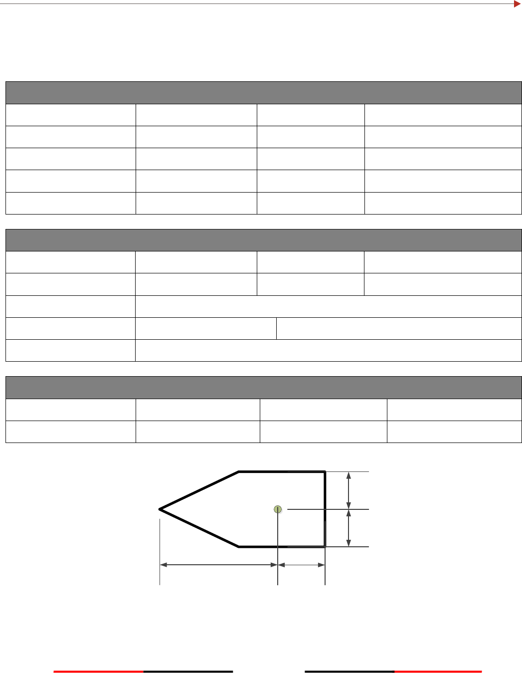
104
APPENDIX (C)
Installation and Maintenance Record
The following installation record should be completed and retained on board the vessel for maintenance
records.
Vessel Information
Vessel Name
Flag State
IMO Number
MMSI Number
Owner/Company
Radio call sign
Type of vessel
Gross tonnage
Length
m
Beam
m
AIS Class A Transponder Information
Transponder S/N
Pilot Plug S/N
Junction Box S/N
GPS Ant. S/N
Password
Power supply
Voltage: V
Maximum output current: A
Note
GPS/GNSS Antenna Location
A= Distance to Bow
m
C= Dist. To Port-Side
m
B= Distance to Stern
m
D= Dist. To Starboard
m
A B
C
D

105
Connected Sensors and Devices
Connected Port
Equipment
Model Number
Sensor 1
Sensor 2
Sensor 3
Ext Display Port
Pilot Port
Long Range Port
DGNSS Data Port
Other Device
Installer Information
Company Name
Technician’s Name
Telephone/Mobile No.
Address
Place
Date
Installer’s Signature

106
Software Revisions
The transponder is delivered with software version according to the following table which is to be filled in and
maintained either by manufacturer, distributor, dealer, or installation company. When software update is
done, the new software (firmware) version can be identified through MKD at MENU/DIAGNOSTICS/VERSION
(please refer to section 4.10.10 in the manual). Each new software upgrade requires information recorded to
reflect the change made.
Note:
Software Maintenance Record
Software Version
By
Date
Change
1.0.6.23
AMEC
2013.04.12
Initial release