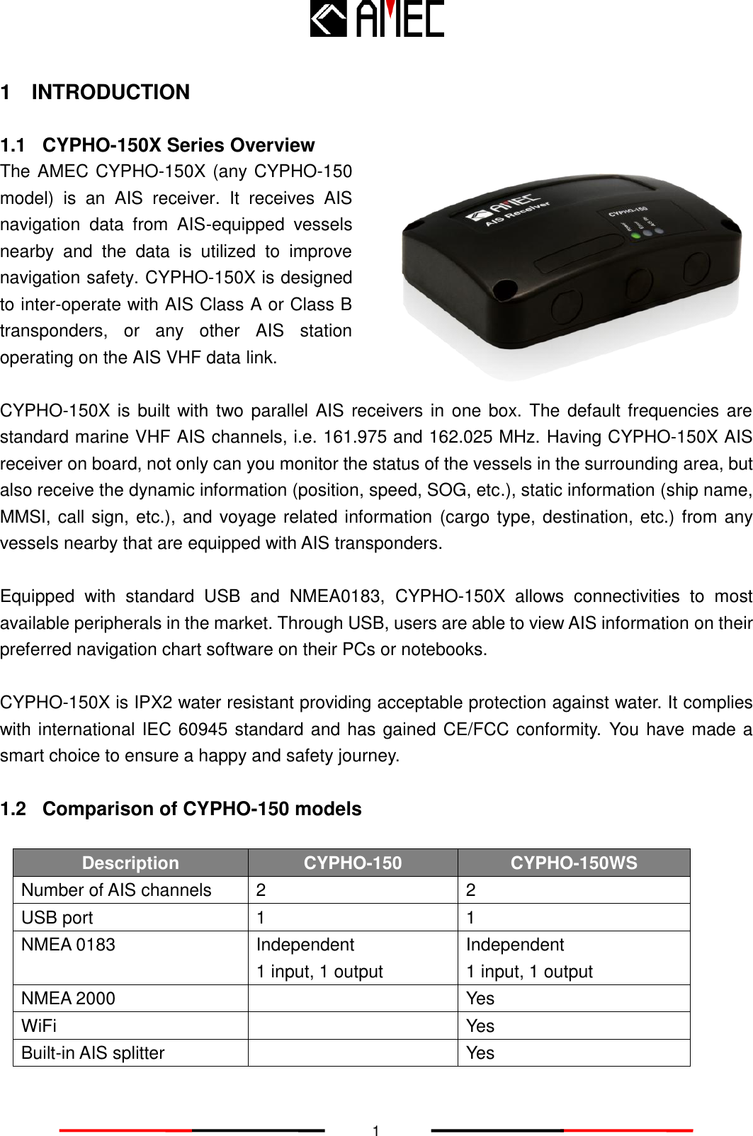
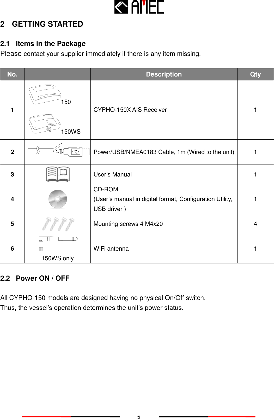
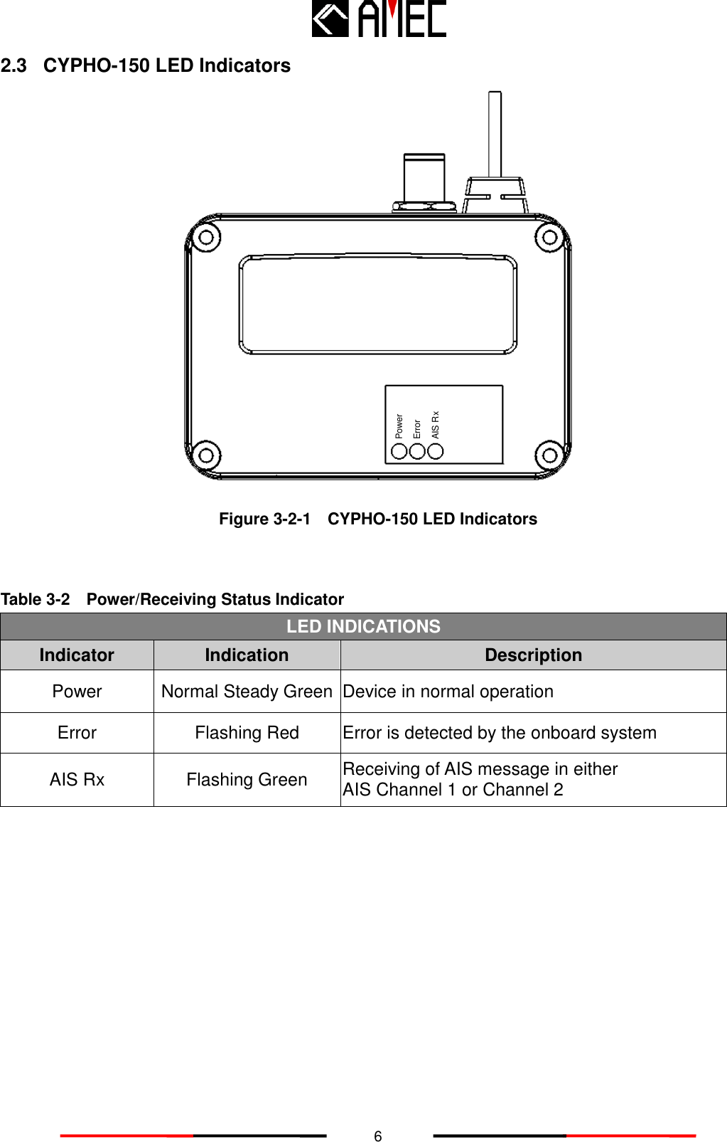
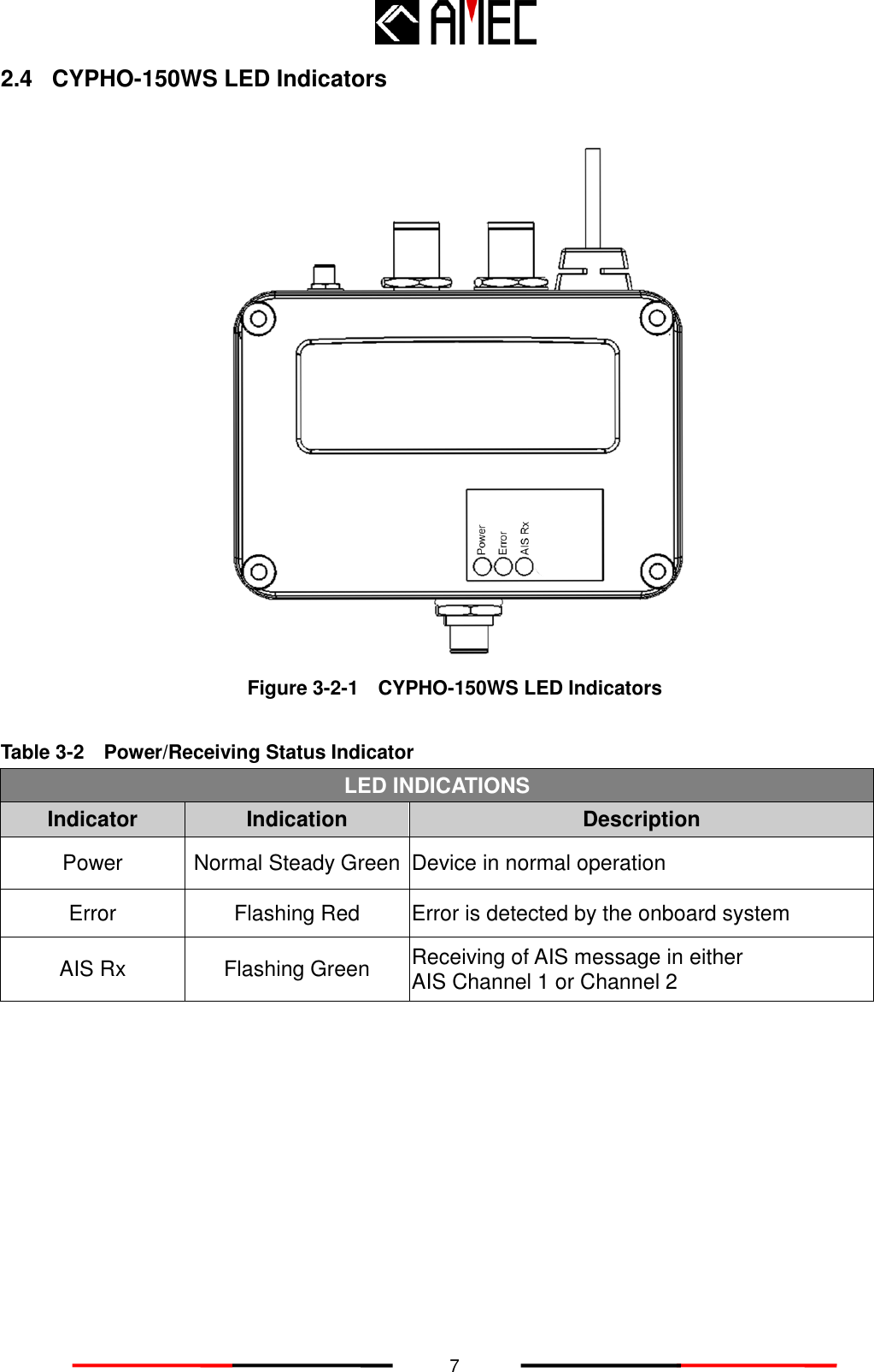
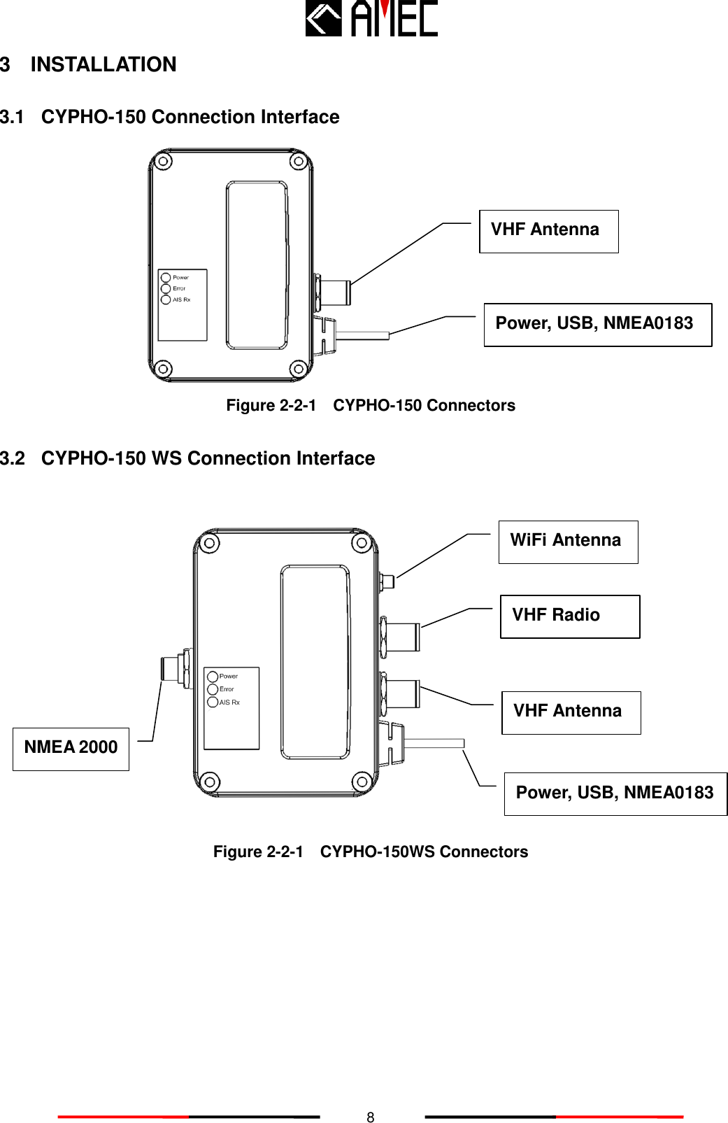
Alltek Marine Electronics AR150WS AIS Receiver User Manual Table of Contents
Alltek Marine Electronics Corporation AIS Receiver Table of Contents
UserManual.wiki
>
Alltek Marine Electronics
>
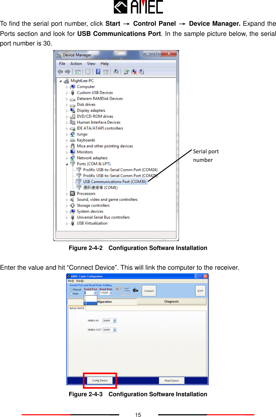
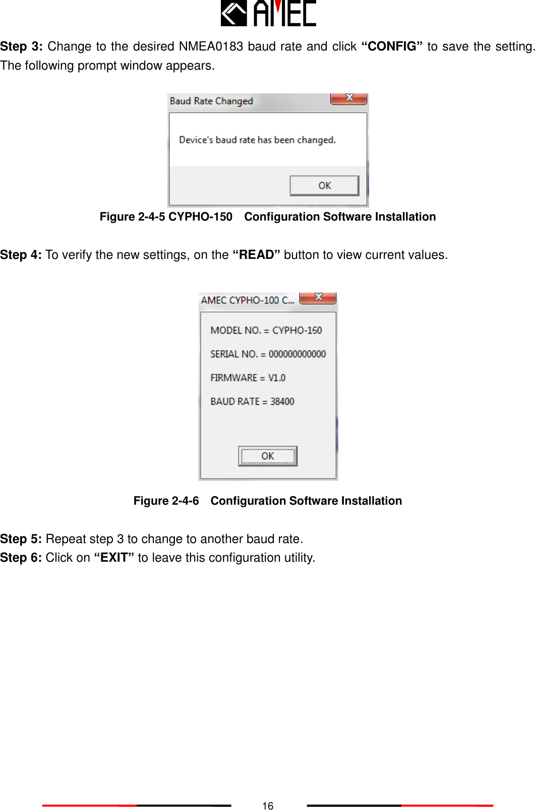
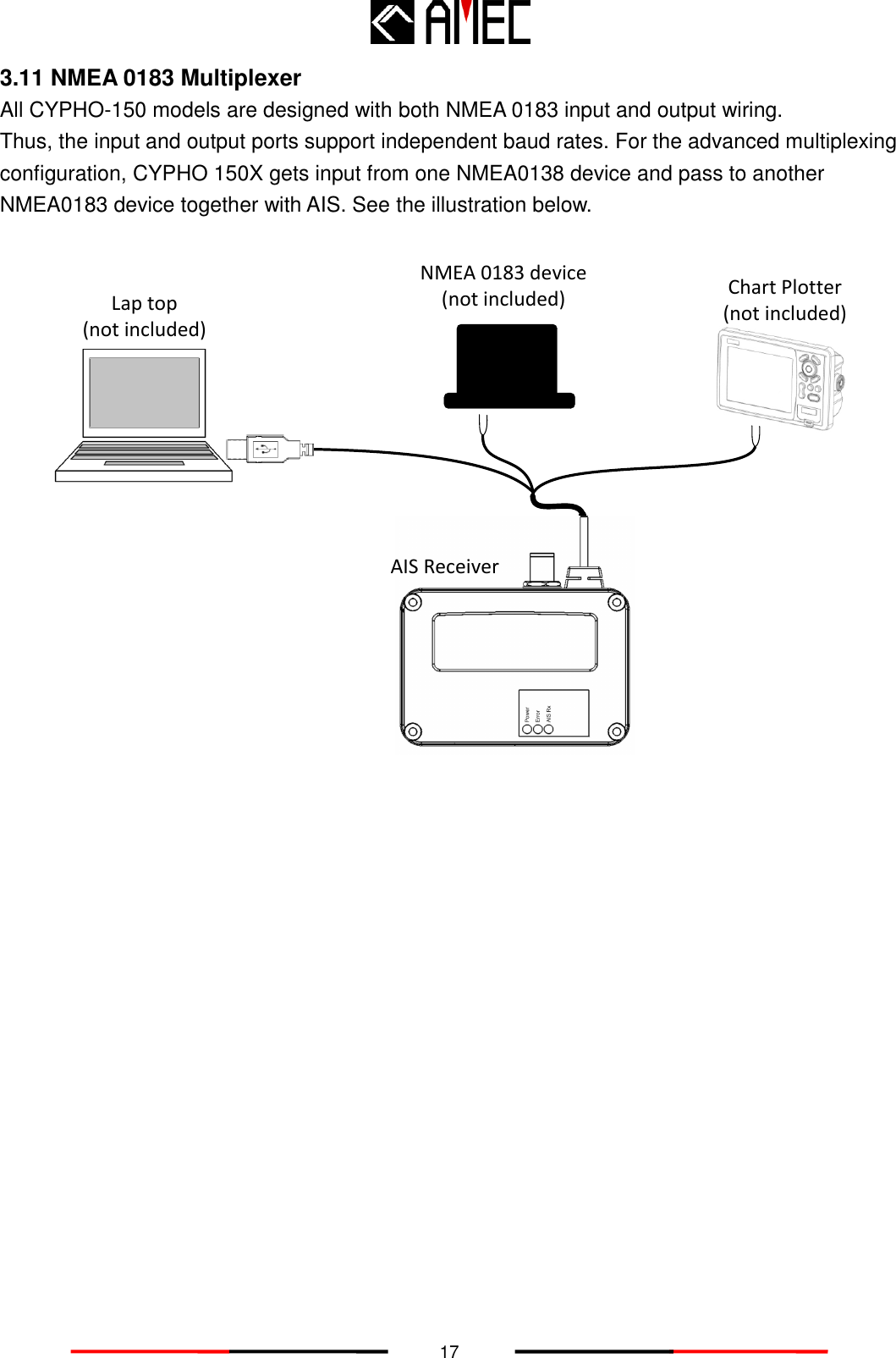
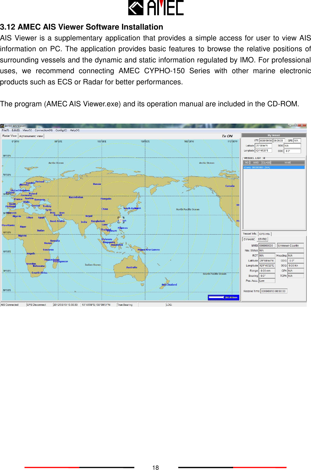
AR150WS User Manual
User manual
Navigation menu
Upload a User Manual
Namespaces
Wiki Guide
HTML
PDF
Info
Views
User Manual
Discussion / Help
Navigation