Alltek Marine Electronics AR150WS AIS Receiver User Manual Table of Contents
Alltek Marine Electronics Corporation AIS Receiver Table of Contents
User manual

User’s Manual
CYPHO-150WS

I
Copyright
The entire contents of this instruction manual, including any future contents updates,
revisions, and specification modifications, shall remain the property of Alltek Marine
Electronics Corp. (hereinafter called AMEC) at all times. Unauthorized copies or
reproduces of this manual, either in part or as a whole, is prohibited. The contents herein
can only be used for the purpose subjects to this manual.
Disclaimer
The contents of this manual are well prepared by AMEC. As we are constantly improving
our products, AMEC shall incur no liability based on the contents, updates or modification
of the contents, or the lack of contents in this manual.
Contact us at:
Technical Support:
Sales & Marketing:
ALLTEK MARINE ELECTRONICS CO., LTD
7F, NO. 605, Ruei-Guang RD., Neihu, Taipei, Taiwan 114
TEL: +886 2 2627 1599
FAX: +886 2 2627 1600
www.alltekmarine.com
(Your Local Dealer/Agent Warranty Stamp)
Version 1.00
II
WARNING
The equipment said in this manual must only be used to which it was designed. Improper
operation or installation may cause damages to the equipment or personal injury. AMEC
will not incur any liability of equipment damage or personal injury due to improper use or
installation of the equipment. It is strongly recommended to read this manual and the
following safety instructions before proceeding to installation or operation.
SAFETY INSTRUCTIONS
ELECTRICAL SHOCK HAZARD
Do not disassemble equipment.
Only qualified personnel could
work inside the equipment.
Improper disassemble or
modification could cause
electrical shocks, fire, or personal
injury.
WARNING
WARNING
TURN OFF THE POWER IMMEDIATELY
IF WATER LEAKS INTO THE
EQUIPMENT OR OBJECT DROPS INTO
THE EQUIPMENT.
Continue operating the equipment could
cause electrical shock or fire. Contact your
nearest distributor for service.
TURN OFF THE POWER BEFORE
PROCEEDING WITH INSTALLATION.
Proceeding with installation with the
power on could cause electrical shock
or fire.
EVEN THOUGH THE EQUIPMENT IS
WATERPROOF, PLEASE AVOID
DIRECT CONTACT WITH RAIN OR
SPLASHING WATER.
Electrical shock or fire could be resulted
if water leaks into the equipment.
AVOID OPERATING THE EQUIPMENT
WITH WET HANDS.
Electrical shocks could be resulted if
operating with wet hands.
PLEASE USE THE PROPER FUSE.
Damage to the equipment or fire could be
resulted if using the wrong fuse.
Warning Label
A warning label (Figure 2-1-1) is
attached underneath the equipment.
Warranty of the equipment will be invalid
if this label is detached or broken.
AMEC and your local agent/dealer will
not bare any responsibility of any
damage to the equipment, or damage in
related to the equipment, personnel
injury, and etc. Reject the equipment if
this label is detached or broken. Please
contact your local agent/dealer if this
label is missing.
WARNING
Name: Warning Label
No Warranty if this label
is detached or broken.
保固撕毁无效
Warning
注意
MAKE SURE THE POWER SOURCE
AND THE POWER INPUT OF THE
EQUIPMENT ARE COMPATIBLE.
Damage to the equipment and fire could
be resulted if the power sources are not
correct. Please check the correct power
input on the adaptor.

III
FOREWORD
ALLTEK MARINE ELECTRONICS (hereinafter called “AMEC”) thank you for choosing our
CYPHO-150 Series Automatic Identification System Receiver. No matter where you sail, you can
enjoy your voyage journey more having a better control on your surrounding sea with
CYPHO-150 AIS receiver series onboard.
The equipment you have purchased is designed with precision performance and quality. Each of
AMEC’s equipment has been strictly tested to meet the rigorous demands of the marine
environment. Unless improper use or false installation or maintenance, the equipment should
function at its best.
Thank you again for choosing AMEC product and wish you bon voyage!

IV
1 INTRODUCTION .............................................................................................. 1
1.1 CYPHO-150X Series Overview ...................................................................................... 1
1.2 Comparison of CYPHO-150 models ............................................................................... 1
1.3 Type of AIS ..................................................................................................................... 2
1.4 AIS Message Type .......................................................................................................... 2
1.5 About This Manual .......................................................................................................... 3
1.6 Important Notice.............................................................................................................. 4
2 GETTING STARTED ........................................................................................ 5
2.1 Items in the Package ...................................................................................................... 5
2.2 Power ON / OFF ............................................................................................................. 5
2.3 CYPHO-150 LED Indicators ........................................................................................... 6
2.4 CYPHO-150WS LED Indicators ...................................................................................... 7
3 INSTALLATION ................................................................................................ 8
3.1 CYPHO-150 Connection Interface .................................................................................. 8
3.2 CYPHO-150 WS Connection Interface ........................................................................... 8
3.3 Installation Precautions ................................................................................................... 9
3.4 Mounting Instructions ...................................................................................................... 9
3.5 Wiring Instructions Applicable to all CYPHO 150 models. ............................................ 10
3.6 VHF Antenna Installation .............................................................................................. 11
3.7 WiFi Antenna Installation (CYPHO-150WS model only) ............................................... 11
3.8 Antenna Cabling ........................................................................................................... 12
3.9 USB Driver Installation .................................................................................................. 13
3.10 CYPHO Configuration Software Installation .............................................................. 14
3.11 NMEA 0183 Multiplexer ............................................................................................. 17
3.12 AMEC AIS Viewer Software Installation ..................................................................... 18
4 APPENDIX ..................................................................................................... 19
4.1 Product Specifications .................................................................................................. 19
4.2 Dimensions ................................................................................................................... 21
4.3 Accessories (Optional) .................................................................................................. 22
4.4 NMEA 2000 PGN Information (150WS Model only) ...................................................... 23
5 AMEC WORLDWIDE WARRANTY ................................................................ 24
6 FCC INTERFERENCE STATEMENT ............................................................. 26


1
1 INTRODUCTION
1.1 CYPHO-150X Series Overview
The AMEC CYPHO-150X (any CYPHO-150
model) is an AIS receiver. It receives AIS
navigation data from AIS-equipped vessels
nearby and the data is utilized to improve
navigation safety. CYPHO-150X is designed
to inter-operate with AIS Class A or Class B
transponders, or any other AIS station
operating on the AIS VHF data link.
CYPHO-150X is built with two parallel AIS receivers in one box. The default frequencies are
standard marine VHF AIS channels, i.e. 161.975 and 162.025 MHz. Having CYPHO-150X AIS
receiver on board, not only can you monitor the status of the vessels in the surrounding area, but
also receive the dynamic information (position, speed, SOG, etc.), static information (ship name,
MMSI, call sign, etc.), and voyage related information (cargo type, destination, etc.) from any
vessels nearby that are equipped with AIS transponders.
Equipped with standard USB and NMEA0183, CYPHO-150X allows connectivities to most
available peripherals in the market. Through USB, users are able to view AIS information on their
preferred navigation chart software on their PCs or notebooks.
CYPHO-150X is IPX2 water resistant providing acceptable protection against water. It complies
with international IEC 60945 standard and has gained CE/FCC conformity. You have made a
smart choice to ensure a happy and safety journey.
1.2 Comparison of CYPHO-150 models
Description
CYPHO-150
CYPHO-150WS
Number of AIS channels
2
2
USB port
1
1
NMEA 0183
Independent
1 input, 1 output
Independent
1 input, 1 output
NMEA 2000
Yes
WiFi
Yes
Built-in AIS splitter
Yes

2
1.3 Type of AIS
There are different types of AIS device as described below. The CYPHO-150X is an AIS receiver.
Table 1-2 Type of AIS
Class A AIS
Transponder
‧ Transmits and receives AIS signal.
‧ Intended for vessels meeting the requirements of IMO AIS carriage
requirement.
‧ It is mandatory for all commercial vessels that exceed 300 tons to be
equipped with Class A AIS.
Class B AIS
Transponder
‧ Transmits and receives AIS signal.
‧ Not necessarily in full accord with IMO AIS carriage requirements.
‧ It is not mandatory for vessels to be equipped with Class B AIS.
‧ Suitable for recreational vessel, in enhancing its safety at sea.
AIS
Receiver
‧ Only receives AIS signal.
‧ Does not have transmitter to send out AIS signal.
‧ Suitable for recreational vessel that does not want to send out its vessel
information.
1.4 AIS Message Type
The CYPHO-150X can receive AIS messages from both class A and class B AIS transponders.
The message types are listed as below table. The messages in gray color are transmitted only
from class A AIS device.

3
Table 1-3 AIS Message Type
Type of Message
Data Details
Static Data
Maritime Mobile Service Identity (hereinafter called “MMSI”) number
IMO number
Call sign and name
Type of ship
Length and beam
GPS Antenna location
Voyage Related
Data
Draught of the ship
Cargo information
Destination
Estimate Time of Arrival (hereinafter called “ETA”)
Dynamic Data
Position of the vessel
Coordinated Universal Time (hereinafter called “Time in UTC”.)
Course Over Ground (hereinafter called “COG”)
Speed Over Ground (hereinafter called “SOG”)
Heading
Rate of turn
Navigational status
Dynamic Reports
Speed of the ship
Status of the ship
SRM
Alarm
Safety
1.5 About This Manual
The manual contains installation instructions and operating information for different CYPHO-150
models. While most of the installation can be performed by the owner or the crew, a final
commissioning can be done by your local agent/dealer when needed or required. AMEC and the
local agent/dealer will not bear any responsibilities over any damages resulted in improper
installation by unauthorized agent/dealer.

4
1.6 Important Notice
The intended use of the AMEC CYPHO-150 Series Automatic Identification System Receiver is
to enhance the safety of vessels at sea. However, a few points must be addressed:
Under certain regulations, some specified vessels are compulsory to be installed with AIS.
However, this does NOT mean that all vessels will be equipped with ones. Any AIS will NOT
guarantee to monitor and to receive signals from every ship in the surroundings.
AIS acts as aids to navigation in the purpose of decreasing or preventing the possibility of
vessel collision. It is not the absolute navigational equipment and does not replace any
navigational system installed on board.
Please keep the device at least 3.3 ft (1 m) away from the ship’s navigation compass.
This product is a marine AIS receiver intended for worldwide use on NON SOLAS vessels.
5
2 GETTING STARTED
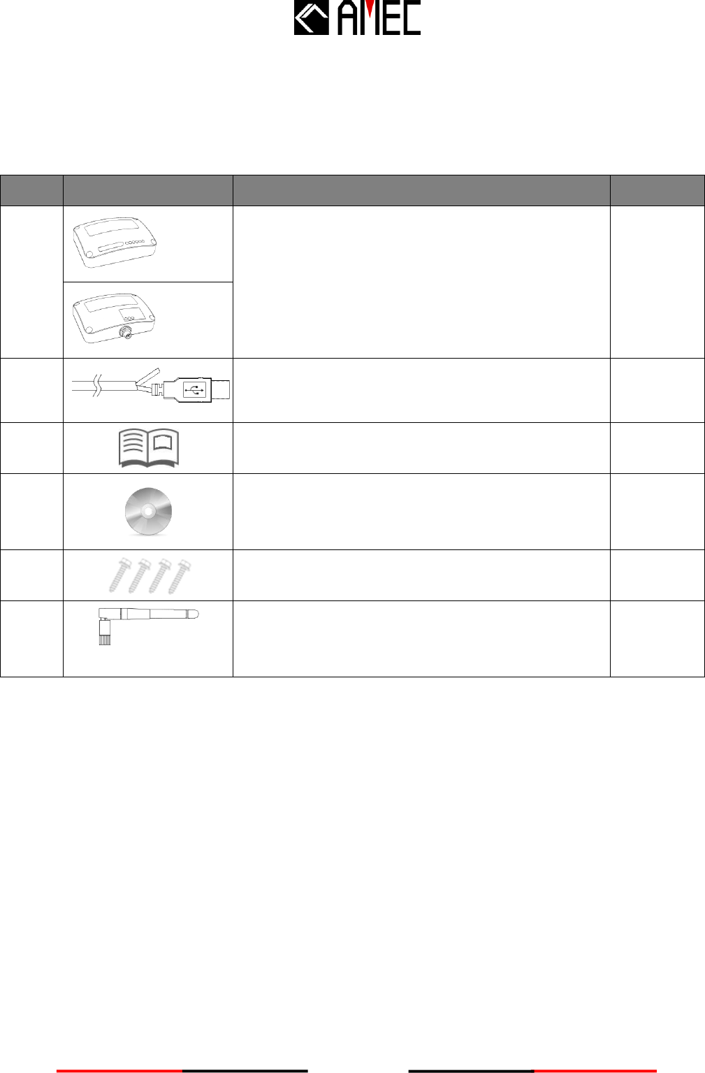
2.1 Items in the Package
Please contact your supplier immediately if there is any item missing.
No.
Description
Qty
1
150
CYPHO-150X AIS Receiver
1
150WS
2
Power/USB/NMEA0183 Cable, 1m (Wired to the unit)
1
3
User’s Manual
1
4
CD-ROM
(User’s manual in digital format, Configuration Utility,
USB driver )
1
5
Mounting screws 4 M4x20
4
6
150WS only
WiFi antenna
1
2.2 Power ON / OFF
All CYPHO-150 models are designed having no physical On/Off switch.
Thus, the vessel’s operation determines the unit’s power status.
6
2.3 CYPHO-150 LED Indicators
Figure 3-2-1 CYPHO-150 LED Indicators
Table 3-2 Power/Receiving Status Indicator
LED INDICATIONS
Indicator
Indication
Description
Power
Normal Steady Green
Device in normal operation
Error
Flashing Red
Error is detected by the onboard system
AIS Rx
Flashing Green
Receiving of AIS message in either
AIS Channel 1 or Channel 2
Power
Error
AIS Rx
7
2.4 CYPHO-150WS LED Indicators
Figure 3-2-1 CYPHO-150WS LED Indicators
Table 3-2 Power/Receiving Status Indicator
LED INDICATIONS
Indicator
Indication
Description
Power
Normal Steady Green
Device in normal operation
Error
Flashing Red
Error is detected by the onboard system
AIS Rx
Flashing Green
Receiving of AIS message in either
AIS Channel 1 or Channel 2
8
3 INSTALLATION
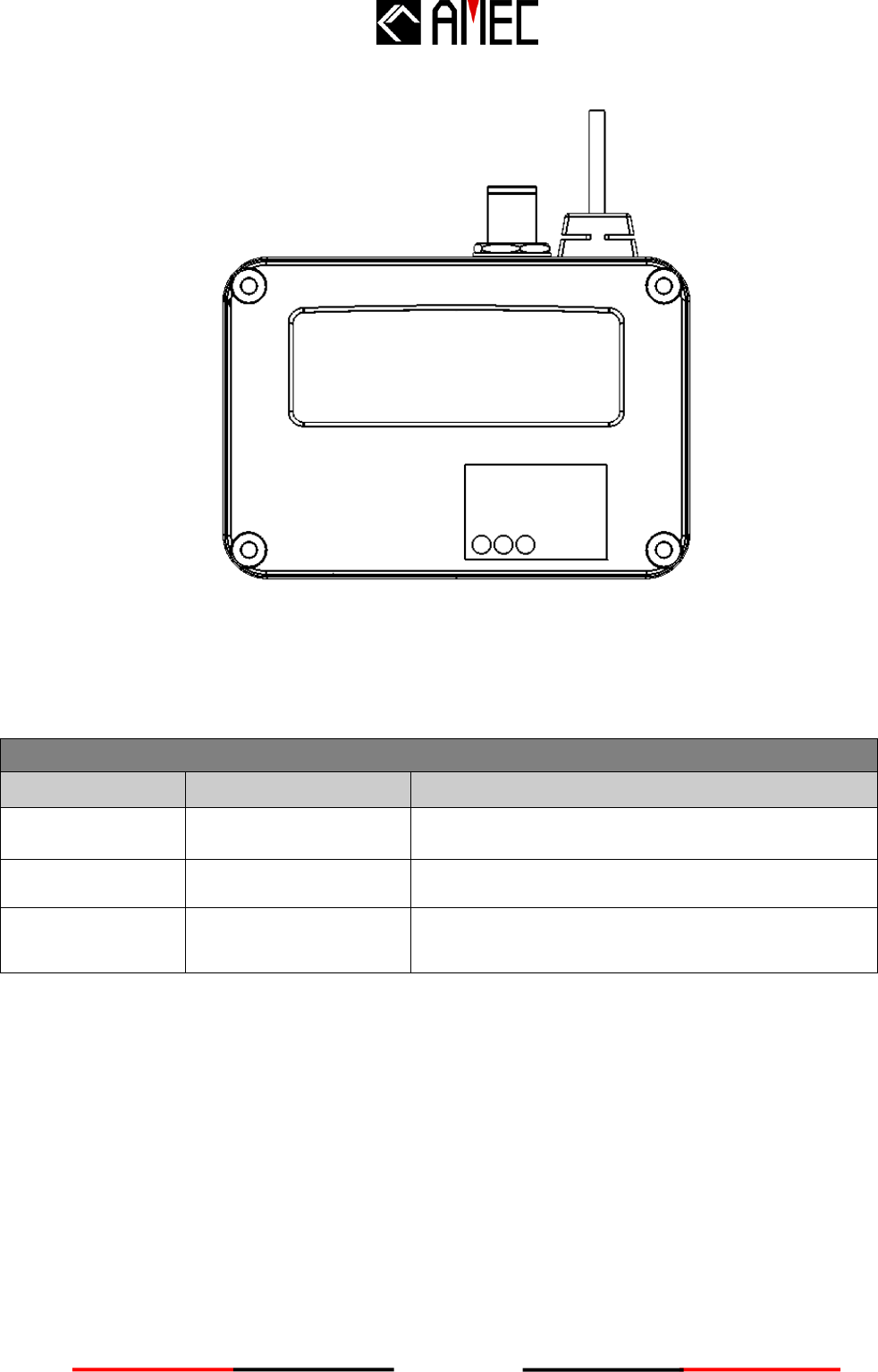
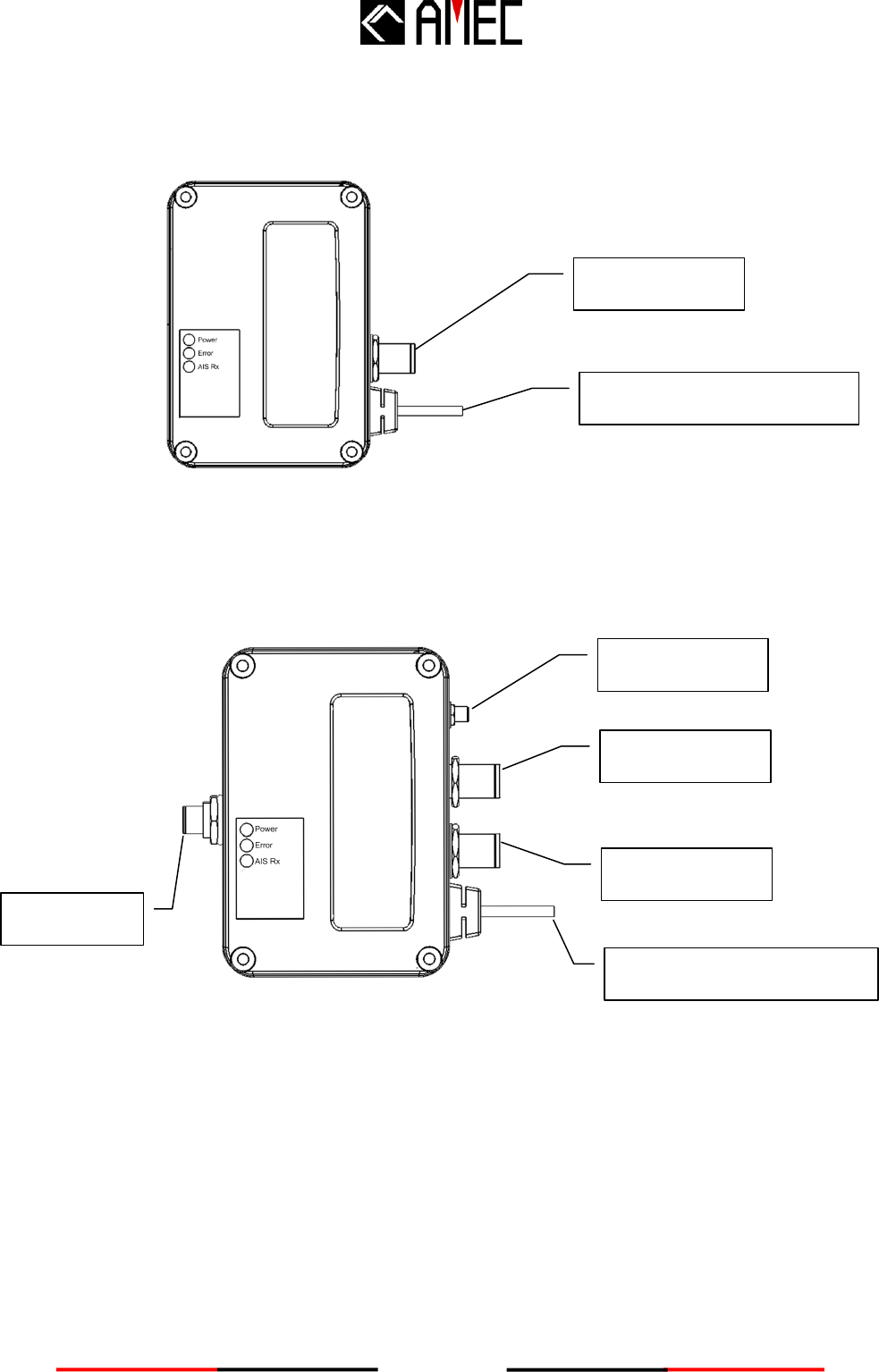
3.1 CYPHO-150 Connection Interface
Figure 2-2-1 CYPHO-150 Connectors
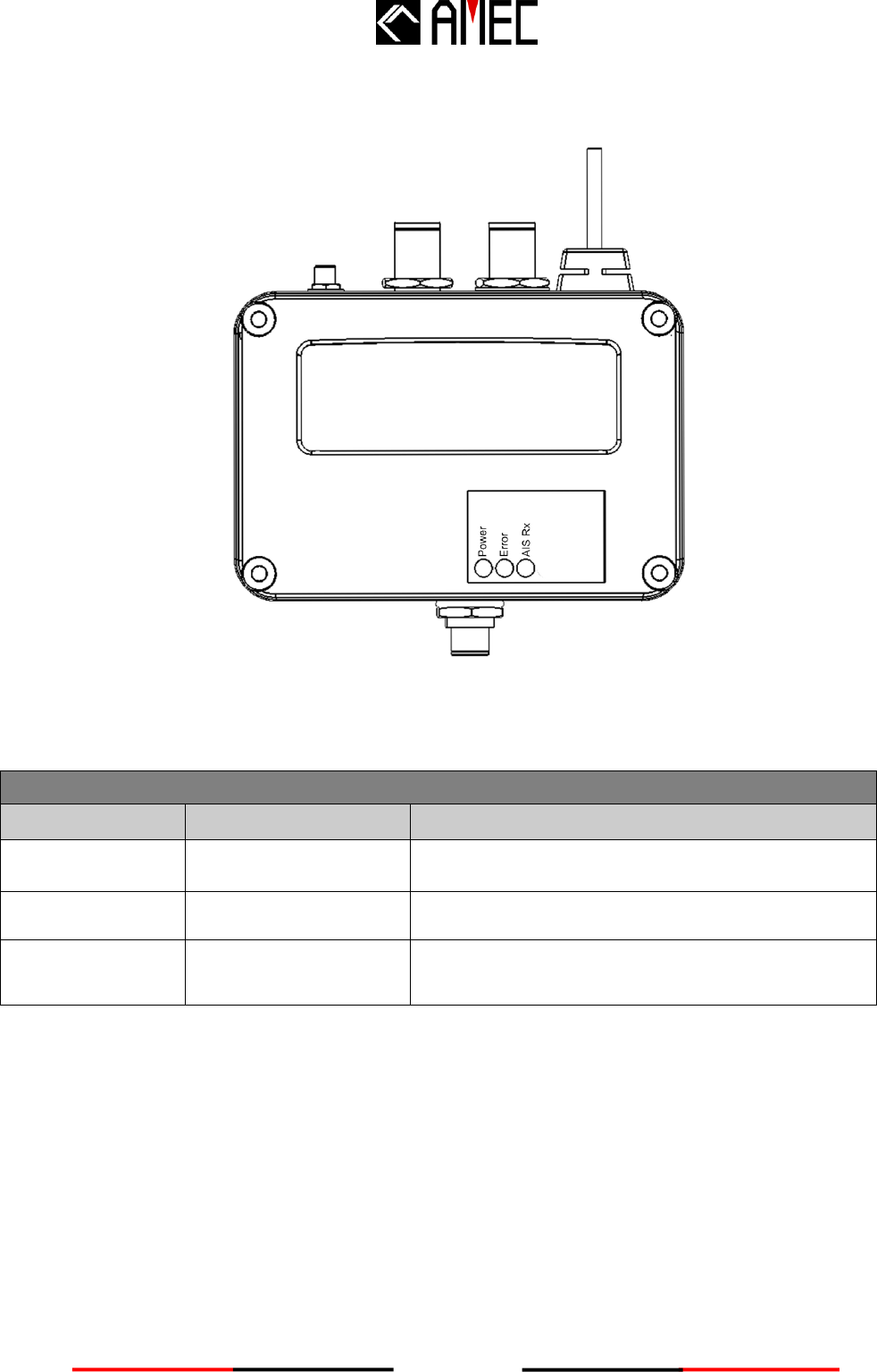
3.2 CYPHO-150 WS Connection Interface
Figure 2-2-1 CYPHO-150WS Connectors
VHF Antenna
Power, USB, NMEA0183
VHF Radio
WiFi Antenna
NMEA 2000
VHF Antenna
Power, USB, NMEA0183
9
3.3 Installation Precautions
CYPHO-150 requires a protected installation environment away from water. Find a proper
location prior to the installation process. If drilling holes are necessary, always wear eye goggle
for protection.
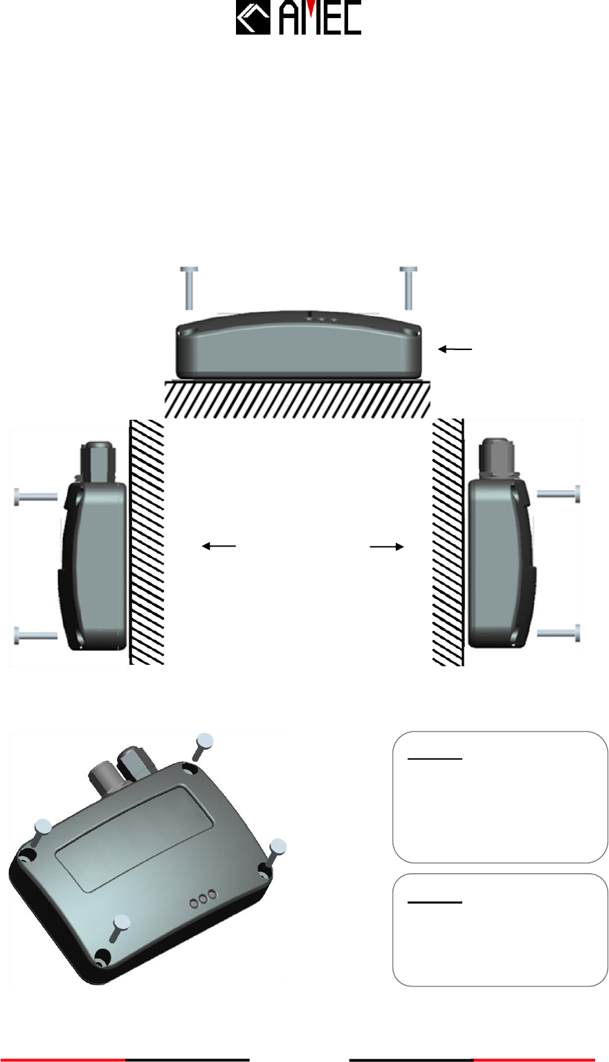
3.4 Mounting Instructions
AMEC CYPHO-150X can be installed and mounted on either flat surface or wall.
Note: the mounting instructions apply to both CYPHO-150 and CYPHO-150WS models.
Figure 2-2-4-2 Installation Instruction
Step 1:
Place the Receiver on the
desired location for
installing.
(Refer to figure 2-2-2-2)
Step 2:
Use the provided M4x20
screws to mount.
(Refer to figure 2-2-2-2)
Wall Mounting
Platform
Mounting
Figure 2-2-4-1 Installation
Overview

10
3.5 Wiring Instructions
Applicable to all CYPHO 150 models.
Figure 2-2-5 Wiring Instruction
When wiring NMEA0183 to your AIS-ready equipment, please refer to your equipment manual
first. CYPHO-150 supports three different baud rates: 4800, 9600, and 38400. The default baud
rate is 38400. To change to other baud rates, requires configuration through the provided
configuration utility.
Receive ─
Receive +
Transmit +
Transmit ─
USB
Power Ground
Power 12/24 V
NMEA 0183
Power
Brown
Blue
Yellow
Green
Red
Black
White __
11
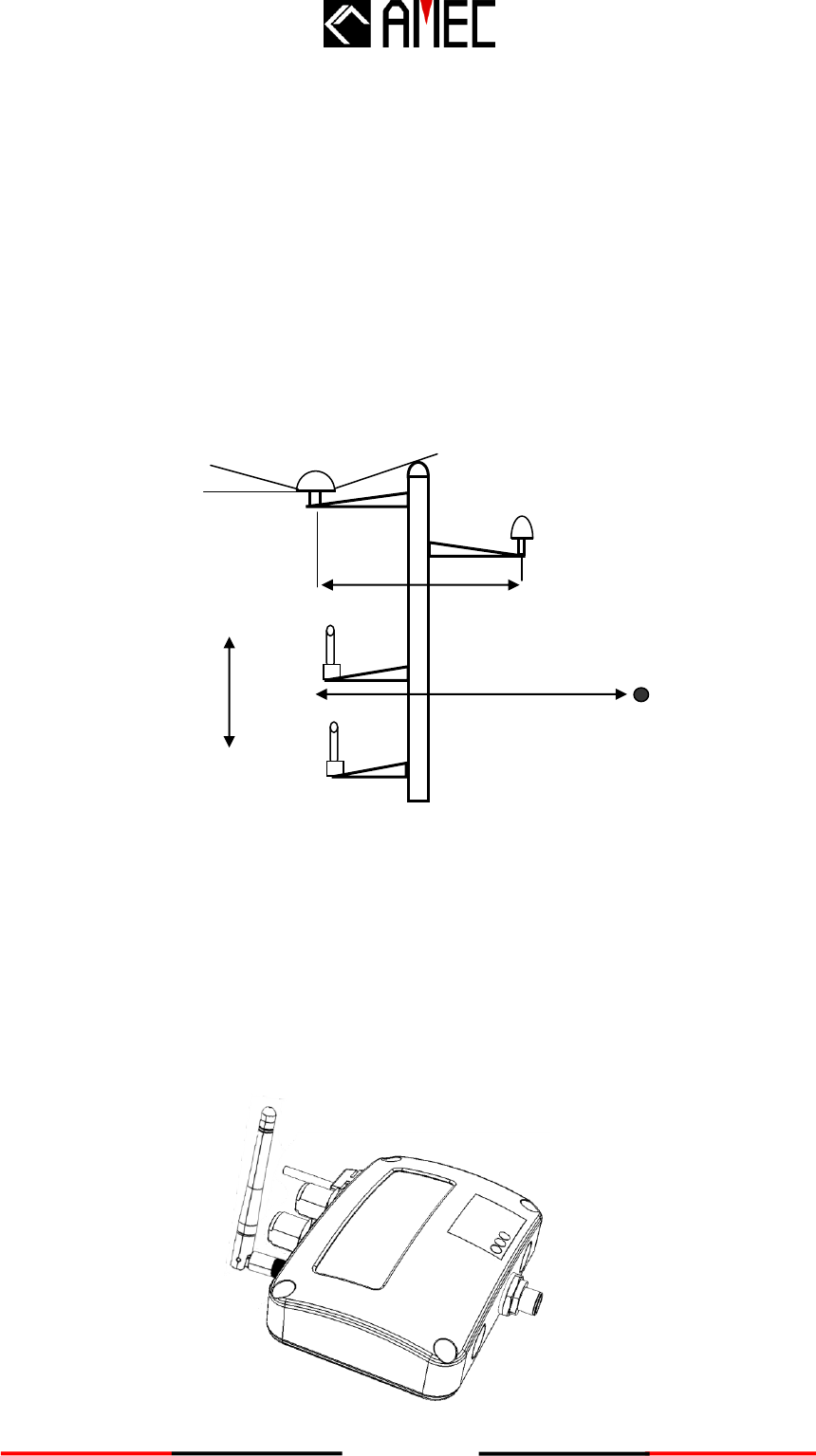
3.6 VHF Antenna Installation
The quality and positioning of the antenna is the most important factor dictating AIS performance.
It is recommended that a VHF antenna with omni directional vertical polarization be specifically
tuned for AIS operation band. Since the range of VHF signals is largely decided by line of sight
distance, AIS antenna should be placed as high as possible and at least 5 meters away from any
constructions made of conductive materials.
To avoid interference, the VHF antenna location should be placed in accordance to Figure 2-2-6.
Figure 2-2-6 VHF/GPS Antenna Location
We recommend you choose AMEC AIS VHF antenna.
3.7 WiFi Antenna Installation (CYPHO-150WS model only)
Installation of WiFi antenna is straight forward. Screw on the antenna firmly and then raise up the
antenna.
Ensure a free 360˚ horizon with
a vertical observation of 5˚.
5˚
High power transmitting antenna
3m
Ensure the GPS antenna is not
within the transmitting beam of other
high power transmitting antenna.
VHF
Antenna.
Other VHF
Antenna
The recommended
vertical distance
between antennas
is 2m.
The
recommended
horizontal
distance between
antennas is 10m.
Other transmitting
antenna
10m
The recommended horizontal
distance between GPS antennas
and other antennas is 3m.

12
3.8 Antenna Cabling
When connecting the cable(s) with the CYPHO-150, take note of the following precautions.
NOTICE
DO NOT BEND CABLES
Bending cables may cause damages to the inner wires and impair
overall the performances.
USES OF CABLE TUBE
Each coaxial cable should be set up separately and can only be set up
in a single cable tube.
INSULATION ON CONNECTING PORT
Connecting port of the coaxial cable should be insulated.
13
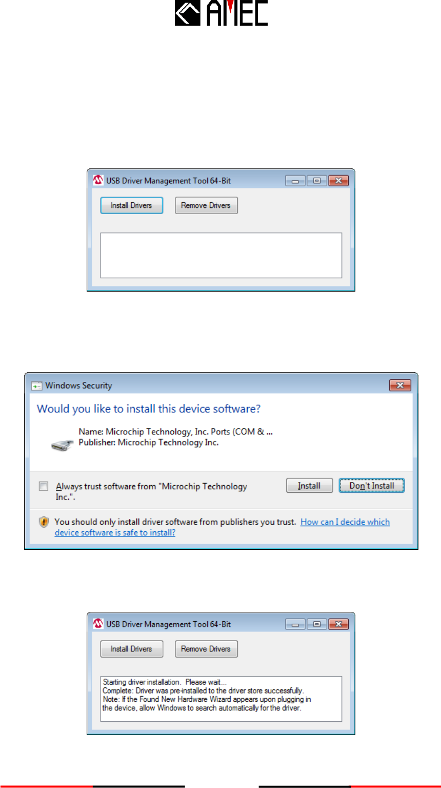
3.9 USB Driver Installation
Your PC needs to install the USB driver in able to connect the AIS receiver. Locate the USB
driver in the CD-ROM. Follow the instructions below to finish the installation.
Step 1: Open the USB Driver file and double click on USBDriverInstaller.exe to install the driver.
Please click on Install Drivers to continue.
Figure 2-3-1 USB Driver Installation
Step 2: A security reminder appears and asks for your confirmation. Click Install to proceed.
Figure 2-3-2 USB Driver Installation
Step 3: Driver installation is completed. Close the window directly using the close window icon.
Figure 2-3-3 USB Driver Installation
14
3.10 CYPHO Configuration Software Installation
The AMEC CYPHO Configuration Software (AmecCypho_Config.exe) configures the onboard
NMEA0183 output rate.
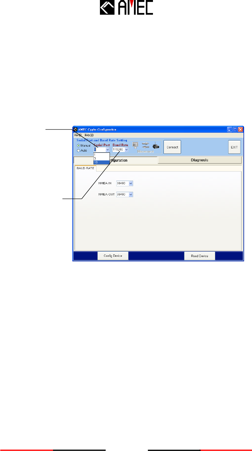
Step1: Double click on AmecCypho_Config.exe
Step2: You may either connect the receiver automatically or manually by using the determined
USB serial port number assigned by the PC.
Figure 2-4-1 Configuration Software Installation
Serial port
number
Baud rate for
NMEA0183
15
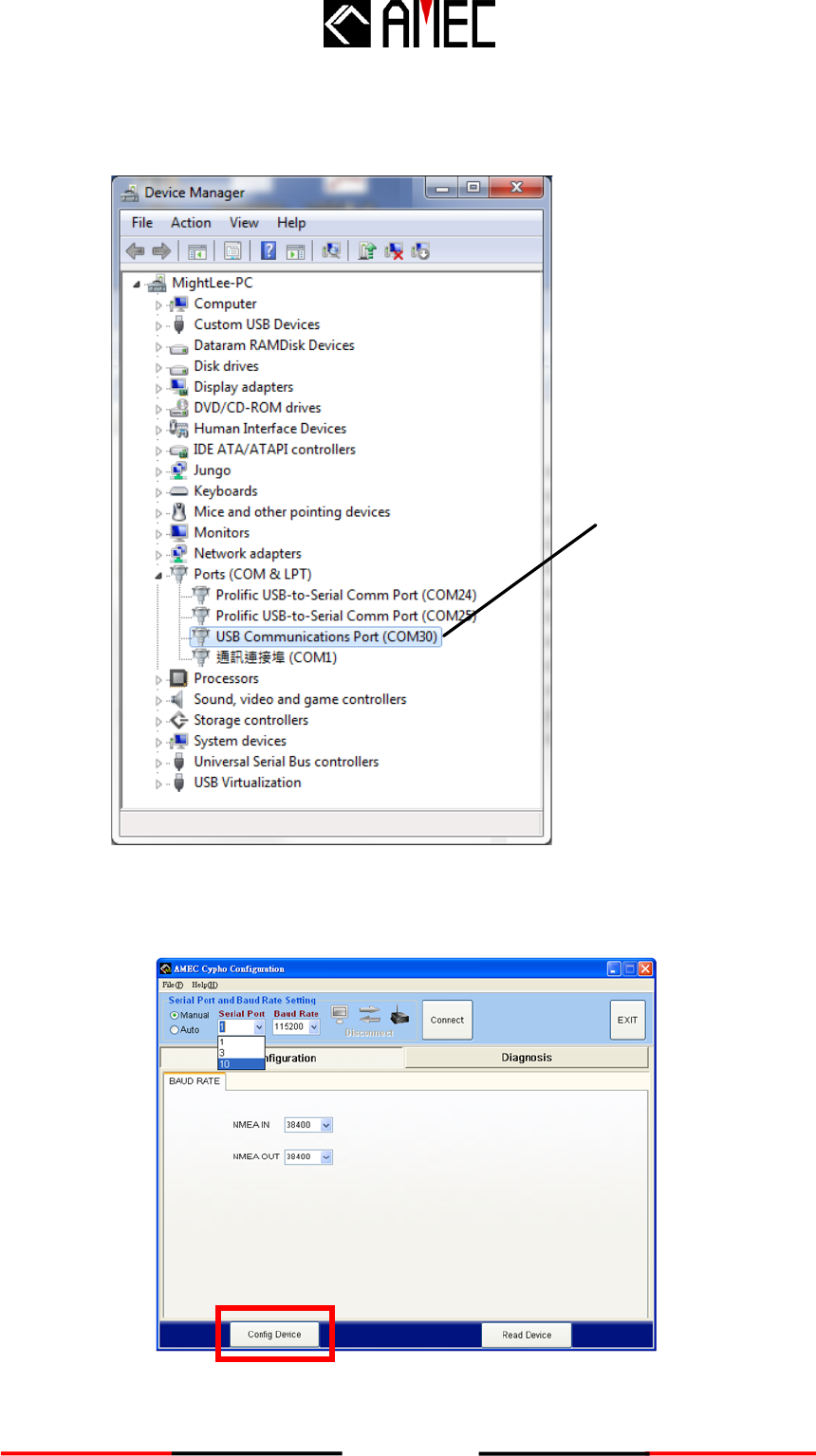
To find the serial port number, click Start → Control Panel → Device Manager. Expand the
Ports section and look for USB Communications Port. In the sample picture below, the serial
port number is 30.
Serial port
number
Figure 2-4-2 Configuration Software Installation
Enter the value and hit “Connect Device”. This will link the computer to the receiver.
Figure 2-4-3 Configuration Software Installation
16
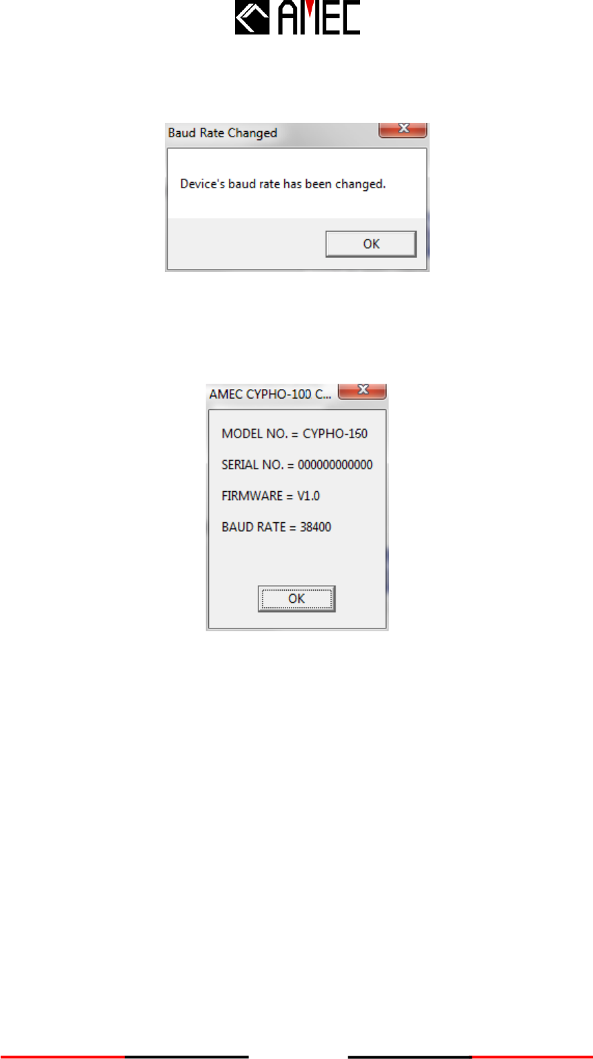
Step 3: Change to the desired NMEA0183 baud rate and click “CONFIG” to save the setting.
The following prompt window appears.
Figure 2-4-5 CYPHO-150 Configuration Software Installation
Step 4: To verify the new settings, on the “READ” button to view current values.
Figure 2-4-6 Configuration Software Installation
Step 5: Repeat step 3 to change to another baud rate.
Step 6: Click on “EXIT” to leave this configuration utility.
17
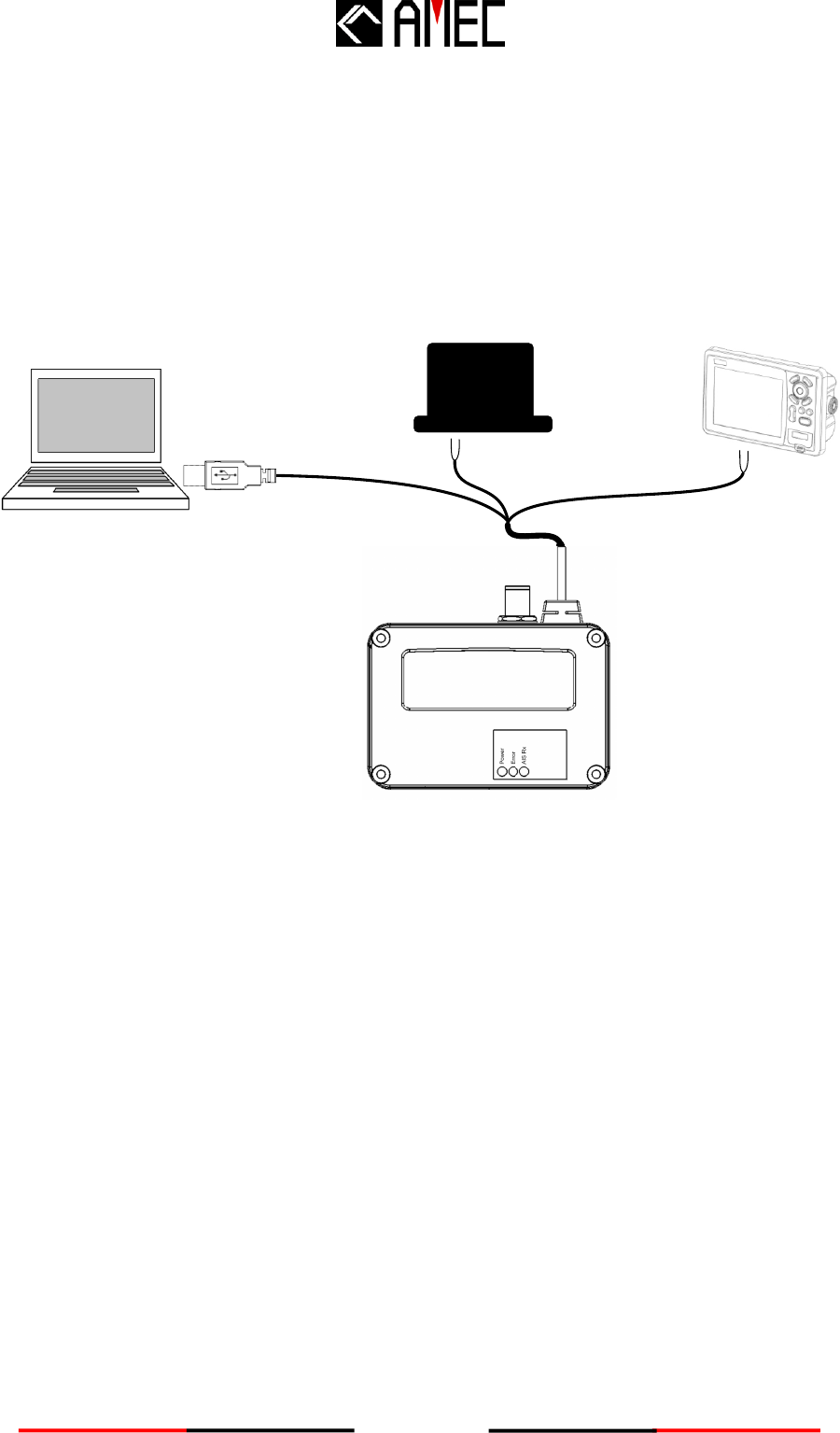
3.11 NMEA 0183 Multiplexer
All CYPHO-150 models are designed with both NMEA 0183 input and output wiring.
Thus, the input and output ports support independent baud rates. For the advanced multiplexing
configuration, CYPHO 150X gets input from one NMEA0138 device and pass to another
NMEA0183 device together with AIS. See the illustration below.
NMEA 0183 device
(not included) Chart Plotter
(not included)
Lap top
(not included)
AIS Receiver
18
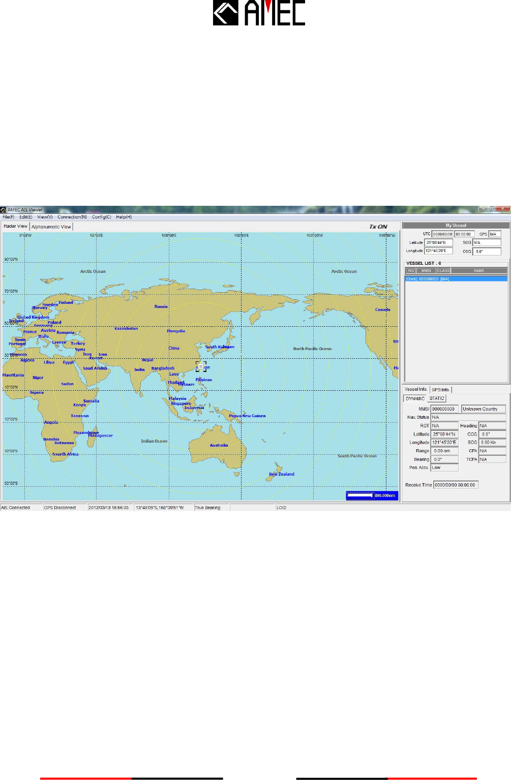
3.12 AMEC AIS Viewer Software Installation
AIS Viewer is a supplementary application that provides a simple access for user to view AIS
information on PC. The application provides basic features to browse the relative positions of
surrounding vessels and the dynamic and static information regulated by IMO. For professional
uses, we recommend connecting AMEC CYPHO-150 Series with other marine electronic
products such as ECS or Radar for better performances.
The program (AMEC AIS Viewer.exe) and its operation manual are included in the CD-ROM.

19
IEC 62287-1 (applicable parts)
ITU-R M.1371 (applicable parts)
IEC 60945 (applicable parts)
IEC 61162 (applicable parts)
POWER SUPPLY
LED INDICATION
12 / 24V DC
<1.50 Watt
Supply Voltage
Power Consumption
CYPHO-150
CYPHO-150WS
Power, Error, AIS Rx
Power, Error, AIS Rx
4 APPENDIX
4.1 Product Specifications
APPLICABLE STANDARDS
VHF RECEIVER
Number of AIS Receivers
CH-1
CH-2
Channel Bandwidth
Message Format
Data Rate
Max. Usable Sensitivity
2 channels
Default CH 87B (161.975MHz)
Default CH 88B (162.025MHz)
25KHz
AIS Class A & B messages
9,600bps / per channel
PER ≤ 20% @ -110 dBm

20
INTERFACE (CYPHO-150WS)
Female Type M (PL 259)
38400 (default), 9600, 4800 bps
Supported
Supported
IEEE 802.11 b/g/n
Supported
PHYSICAL
IEEE 802.11b/g/n
VHF Antenna Connector
NMEA 0183
USB 2.0
NMEA 2000
WiFi
VHF Radio
-15°C~55°C
-25°C~70°C
0~95% RH at 40°C
IEC 60945
IPX2
Operating Temperature
Storage Temperature
Humidity Operation
Vibration
Waterproof
156.025 ~ 162.025
-3.5dB
-1.8dB
Size in mm (w)
Size in mm (h)
Size in mm (d)
Weight
ENVIRONMENTAL
WiFi (CYPHO-150WS model only)
RF PERFORMANCE (CYPHO-150WS model only)
AIS & VHF Radio Frequency Range
VHF port insertion loss:
Receiver path
Transmit path
128mm
36mm
88mm
250g (with cables)

21
4.2 Dimensions
Applicable to all CYPHO-150 models.
Front View
Figure 5-2-1 CYPHO-150 Front View
Side View
Figure 5-2-2 CYPHO-150 Side View
Power
Error
AIS Rx
128 mm
88 mm
36 mm
88 mm 1m

22
4.3 Accessories (Optional)
The following accessories are available from AMEC. Contact our local dealer/agent for more
details.
Table 5-3 Available Accessories
Item
Description
Product Code
Remark
1
VHF Antenna
TENTA-11
Length: 1,200 mm

23
4.4 NMEA 2000 PGN Information (150WS Model only)
Transmit
Receive
PGN
Description
PGN
Description
59392
ISO Acknowledgment
59392
ISO Acknowledgment
59904
ISO Request
59904
ISO Request
60928
ISO Address Claim
60928
ISO Address Claim
126464
PGN List - Transmit PGN's group
function
126996
Product Information
129038
AIS Class A Position Report
129039
AIS Class B Position Report
129040
AIS Class B Extended Position Report
129041
AIS Aids to Navigation (AtoN) Report
129792
AIS DGNSS Broadcast Binary Message
129793
AIS UTC and Date Report
129794
AIS Class A Static and Voyage Related
Data
129795
AIS Addressed Binary Message
129796
AIS Acknowledge
129797
AIS Binary Broadcast Message
129800
AIS UTC/Date Inquiry
129801
AIS Addressed Safety Related Message
129802
AIS Safety Related Broadcast Message
129803
AIS Interrogation
129804
AIS Assignment Mode Command
129805
AIS Data Link Management Message
129806
AIS Class A Position Report
129807
AIS Group Assignment
129808
DSC Call Information
129809
AIS Class B “CS” Static Data Report,
Part A
129810
AIS Class B “CS” Static Data Report,
Part B

24
5 AMEC WORLDWIDE WARRANTY
Limited warranty
Subject to the terms, conditions and limitations set forth in this Worldwide Limited Warranty
(hereinafter the “Warranty”), AMEC warrants that its products, when properly installed and used,
will be free from defects in material and workmanship for a period of twelve (12) months, from the
date of first purchase (the ‘Warranty Period’)
For the purposes of this warranty, ‘date of first purchase’ means the date that the product was
purchased by the first retail customer, or by the institutional customer, or in the case of a product
installed on a new vessel or any other marine related platform by a certified AMEC original
equipment manufacturer (a ‘AMEC OEM’), the date that such vessel was purchased by the first
retail customer.
AMEC will, at its sole option, repair or replace any defective products or components returned
during the Warranty Period in accordance with the terms, conditions and limitations set forth
below. Such repairs or replacement will be the sole remedy of the customer under this
Warranty.
Standard Warranty Service
To qualify for standard warranty service the product must be returned to a AMEC-certified service
agent (i) within the Warranty Period, and (ii) within thirty (30) days of the alleged product failure.
Any products returned must be securely packaged and sent pre-paid and insured to AMEC or to
a AMEC-certified service agent. All products returned must be accompanied by a copy of the
original sales receipt to be eligible for standard warranty service.
Obtaining Warranty Service
A list of AMEC-certified service agents is available from AMEC Technical Support at
www.alltekmarine.com
Other conditions
This Warranty is fully transferable provided that you furnish the original proof of purchase to the
AMEC -certified service agent. This Warranty is void if the label bearing the serial number has
been removed or defaced.
Limitation and Exclusions
In addition to any other limitations and exclusions set forth herein, AMEC is not responsible for,
and this Warranty does not cover:
Failure due to abuse, misuse, accident, unauthorized alteration, modification or repair,

25
improper installation or operation (whether or not by a AMEC-certified service agent) or
improper storage, shipping damage or corrosion;
Costs associated with routine system checkouts, alignment/calibration, sea trials or
commissioning;
Defects or damage that result from the use of non-AMEC branded or certified products,
accessories or other peripheral equipment, including without limitation housings, parts, or
software;
Aftermarket software (i.e. all software other than the original operating software sold with the
products);
Products that have been refurbished, reconditioned, or remanufactured (The foregoing does
not apply to products repaired or replaced pursuant to the terms of this Warranty).
Products that have been dismantled resulting in the broken label on the Products;
Costs associated with overtime or premium labor costs;
Differences in material, coloring or size that may exist between actual products and the
pictures or descriptions of such products in our advertising, advertising literature or on the
Internet;
TO THE EXTENT PERMITTED BY APPLICABLE LAW, THE FOREGOING WARRANTY IS
AMEC’S SOLE WARRANTY AND IS APPLICABLE ONLY TO NEW PRODUCTS
PURCHASED WORLDWIDE. THE PROVISIONS OF THIS WARRANTY ARE IN LIEU OF
ANY OTHER WRITTEN WARRANTY, WHETHER EXPRESSED OR IMPLIED, WRITTEN OR
ORAL, INCLUDING ANY WARRANTY OF MERCHANTABILITY OR FITNESS FOR A
PARTICULAR PURPOSE.
THE LIABILITY OF AMEC TO A CUSTOMER UNDER THIS WARRANTY, WHETHER FOR
BREACH OF CONTRACT, TORT, BREACH OF STATUTORY DUTY OR OTHERWISE SHALL
IN NO EVENT EXCEED AN AMOUNT EQUAL TO THE TOTAL PURCHAE PRICE OF THE
PRODUCT GIVING RISE TO SUCH LIABILITY AND IN NO EVENT SHALL AMEC BE LIABLE
FOR SPECIAL, INCIDENTAL, CONSEQUENTIAL OR INDIRECT DAMAGES OR LOST OF
GOODWILL, REPUTATION, LOSS OF OPPORTUNITY OR INFORMATION, DATA,
SOFTWARE OR APPLICATIONS.
SOME JURISDICTIONS DO NOT ALLOW EXCLUSION OR LIMITATION OF INCIDENTAL OR
CONSEQUENTIAL DAMAGES SO THE ABOVE LIMITATIONS OR EXCLUSIONS MAY NOT
APPLY TO YOU. THIS WARRANTY GIVES YOU SPECIFICLEGAL RIGHTS AND YOU MAY
ALSO HAVE OTHER RIGHTS, WHICH VARY FROM JURISDICTION TO JURISDICTION.
This Warranty supersedes and replaces all previous Warranties.
In the event that any term or provision contained in this Warranty is found to be invalid, illegal or
unenforceable by a court of competent jurisdiction, then such provision shall be deemed

26
modified to the extent necessary to make such provision enforceable by such court, taking into
account the intent of the parties.
No oral or written representations made by AMEC or any seller, reseller or distributor of the
products, including employees and agents thereof, shall create any additional warranty
obligations, increase the scope, or otherwise modify in any manner the terms of this Warranty.
All AMEC products sold or provided hereunder are merely aids to navigation. It is the
responsibility of the user to exercise discretion and proper navigational skill independent of any
AMEC product.
6 FCC INTERFERENCE STATEMENT
This equipment has been tested and found to comply with the limits for a Class A digital device,
pursuant to Part 15 of FCC Rules. These limits are designed to provide reasonable protection
against harmful interference in a residential installation. This equipment generates uses and can
radiate radio frequency energy and, if not installed and used in accordance with the instructions,
may cause harmful interference to radio communications. However, there is no guarantee that
interference will not occur in a particular installation. If this equipment does cause harmful
interference to radio or television reception, which can be determined by turning the equipment
off and on, the user is encouraged to try to correct the interference by one of the following
measures:
Reorient or relocate the receiving antenna.
Increase the separation between the equipment and receiver.
Connect the equipment into an outlet on a circuit different from that to which the receiver is
connected.
Consult the dealer or an experienced radio/TV technician for help.
This device complies with Part 15 of the FCC Rules. Operation is subject to the following two
conditions: 1) This device may not cause harmful interference, and 2) this device must accept
any interference received, including interference that may cause undesired operation.

27
7 DECLARATION OF CONFORMITY
Hereby, Alltek Marine Electronics Corp. (AMEC) declares that this CYPHO-150/150WS is in
compliance with the essential requirements and other relevant provisions of Directive 1999/5/EC.
8 ACRONYMS
AIS
Automatic Identification System
COG
Course Over Ground
CPA
Distance to Closest Point of Approach
CSTDMA
Carrier-sense time division multiple access
DSC
Digital Selective Calling
ECS
Electronic Chart System
ETA
Estimated Time of Arrival
GPS
Global Positioning System
IMO
International Maritime Organization
MMSI
Maritime Mobile Service Identity
SOG
Speed Over Ground
SRM
Safety Related Message
TCPA
Time to Closest Point of Approach
TDMA
Time Division Multiple Access
UTC
Coordinated Universal Time
VHF
Very High Frequency
VTS
Vessel Traffic Service