Altai Technologies CX200 CX200 Outdoor 2x2 802.11ac Wave 2 AP User Manual CX200 Quick Setup Guide
Altai Technologies Limited CX200 Outdoor 2x2 802.11ac Wave 2 AP CX200 Quick Setup Guide
User Manual
Quick Setup Guide
1
Altai Technologies Ltd. All rights reserved
Altai CX200 Outdoor 2x2
8 0 2 . 1 1 a c W a v e 2
AP
_________________________________________________
Quick
Setup
Guide
Version 1.1
Quick Setup Guide
Altai Technologies Ltd. All rights reserved
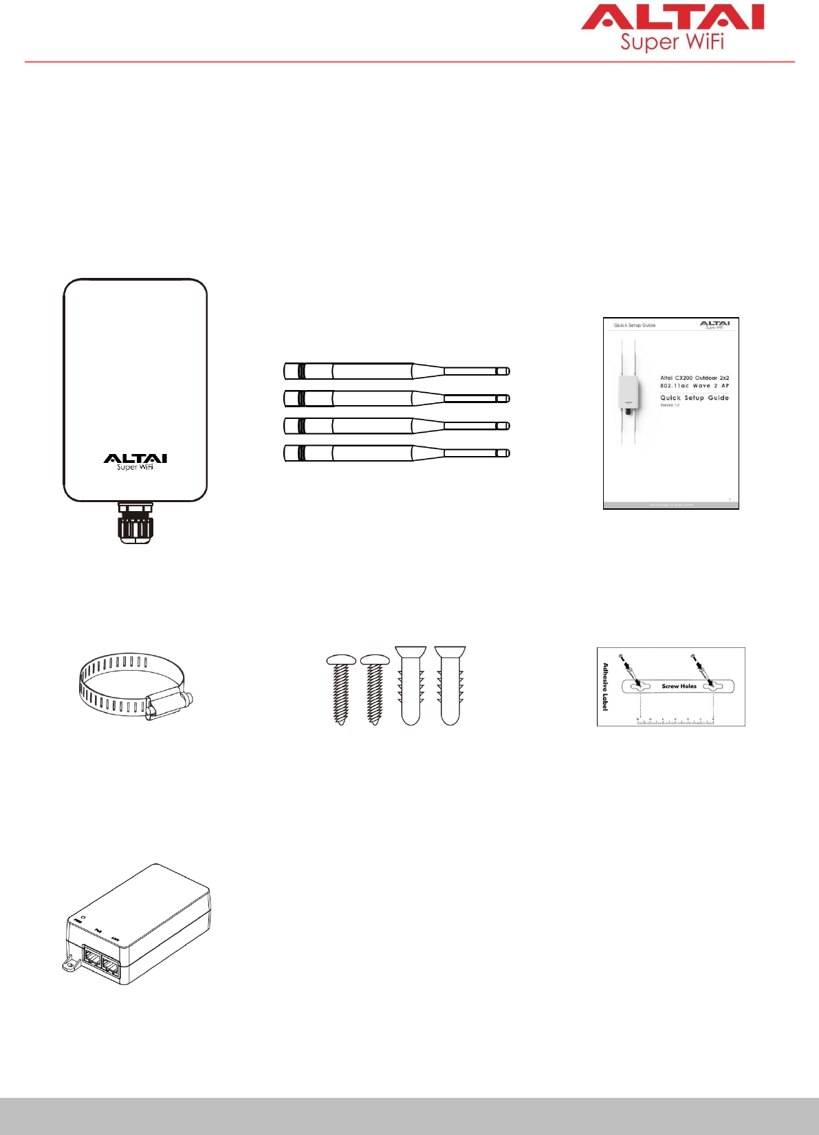
Pole Mount
Hose Clamp
Wall Mount Kit
- Anchors
x 2
- Screws
x 2
Adhesive Label
PoE
I
n
j
ecto
r
(Optional)
Introduction
Thank you for purchasing the Altai CX200 product. This guide provides
instructions to install the product and set it up as AP with minimal effort.
Package Contents
2
CX200 Main Unit
Quick Setup Guide
Detachable Antennae
-
2.4GHz Antenna x 2
-
5GHz Antenna x 2
Quick Setup Guide
3
Altai Technologies Ltd. All rights reserved
LED
I
n
d
i
cat
or
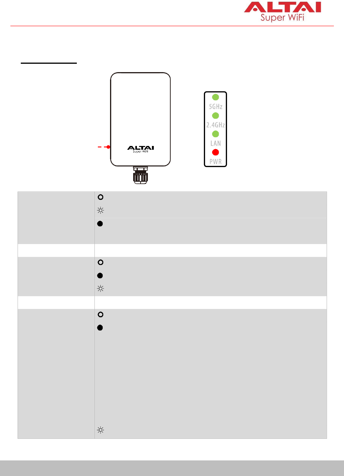
Hardware Overview
LED Indicator
Power
Off AP powered off
Flashing Red AP booting up
Solid Red AP boot up finished and ready for
service
LAN (Ethernet)
Off LAN disconnected
Solid Green LAN connected
Flashing Green Data Transmitting/Receiving
2.4
GHz/5G WiFi
Radios
(AP/Station/
Repeater/Bridge)
Off Radio Disabled
Solid Green 1. AP mode on but with no client
a
ss
o
c
i
a
t
i
o
n
;
OR
2.
Station mode on but not
connected to remote AP; OR
3.
Repeater mode
on but not
connected to remote AP; OR
4.
Bridge mode on but not
connected to remote peer
Flashing Green
Data transmitting/receiving
Quick Setup Guide
4
Altai Technologies Ltd. All rights reserved
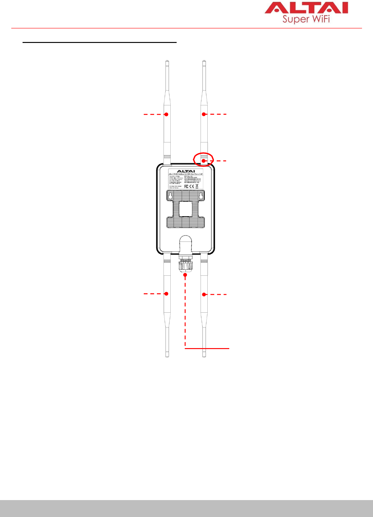
Ethernet Port and RF Antenna Port
5GHz Dipole
Antenna
2.4GHz Dipole
Antenna
NOTE: To ensure correct
antenna connection, check
the labels (2.4GHz/5GHz)
printed on each antenna
body and RF port for easy
reference.
5GHz Dipole
Antenna
2.4GHz Dipole
Antenna
Ethernet Port
Ethernet Port:
Used to connect to power source (see the Power Options in the later section)
and provides 10/100/1000 Mbps network interface for LAN connection.
RF Antenna Ports:
U
s
ed
t
o
at
t
ac
h
2
.
4G
and
5G ant
en
n
ae
fo
r
2x2
M
I
MO
W
i
F
i
ac
cess
cover
ag
e
or bridge connection.
Quick Setup Guide
5
Altai Technologies Ltd. All rights reserved
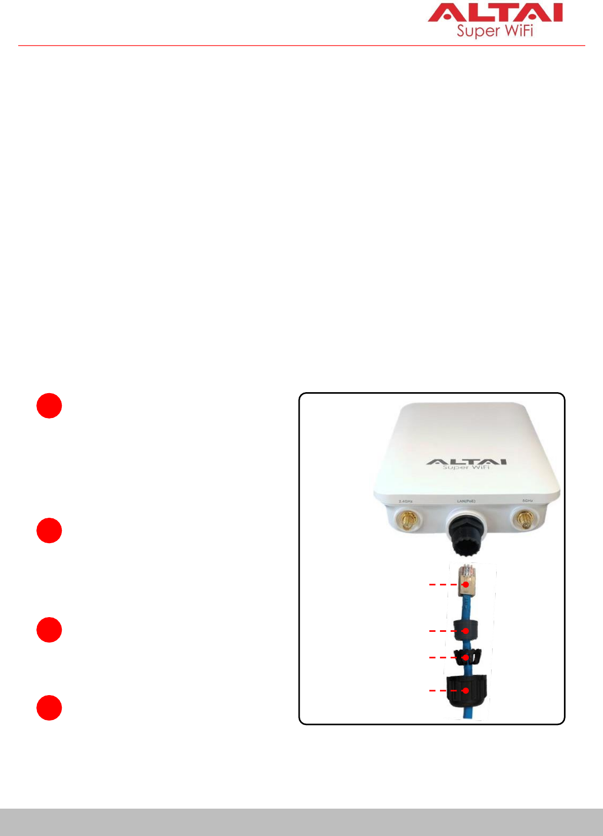
1
Feed the end of the cable
through the cap nut, sleeve
holder, sealing sleeve as
shown in the picture.
Setup Preparation
Wire stripping tool and crimping tool
Screwdriver (Slot type and Phillips type)
Drill and drill bits
Computer with Web Browser: Google Chrome, Mozilla Firefox, or Microsoft
Internet Explorer 8 (or above)
Two Cat 5e/6 Ethernet cables
802.3af-compliant PoE switch
AltaiCare account (Optional) for cloud AP management and user service
Ethernet Cable Feed-Through
Seal the RJ45 cable Connector with the provided cable gland.
3
Connect the cable to the
Ethernet Port.
4
Tighten the cap nut.
RJ45 Connector
Sealing Sleeve
Sleeve Holder
Cap Nut
2
Crimp
the
Ethernet
connector with the crimping
tool.
Quick Setup Guide
6
Altai Technologies Ltd. All rights reserved
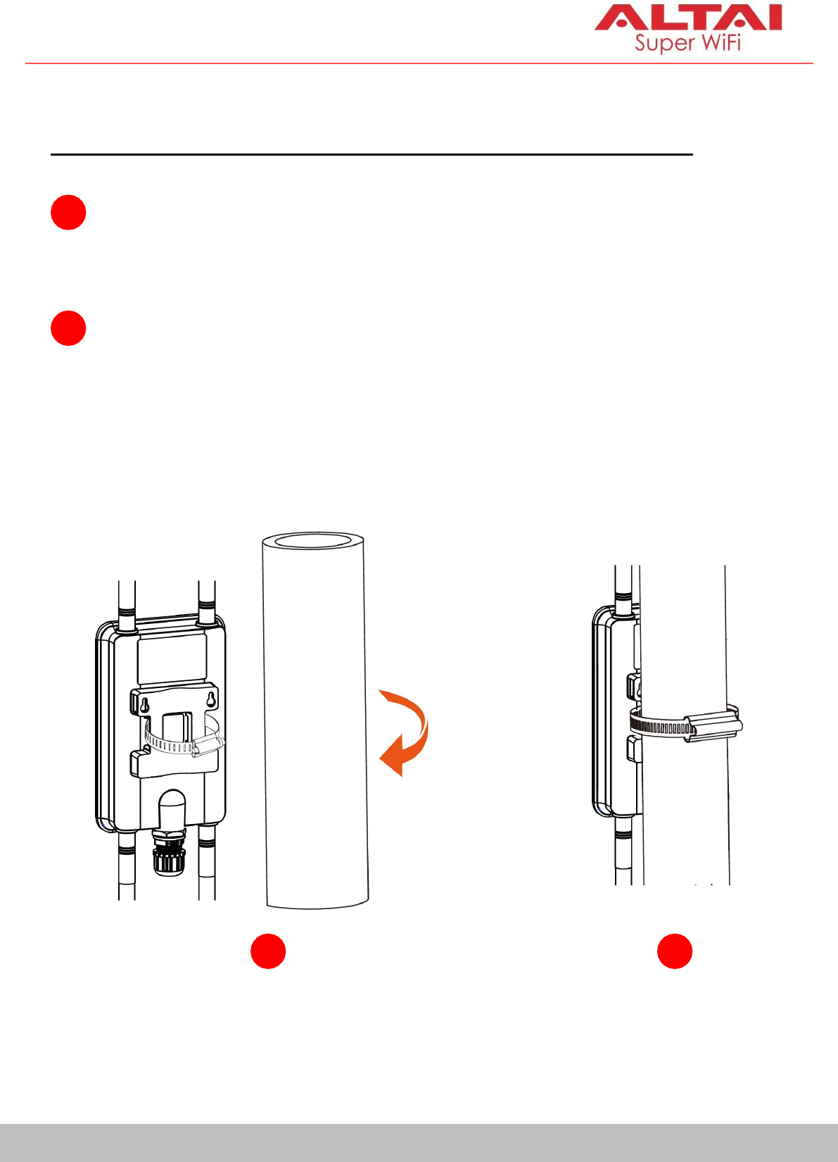
Mounting Options
Option 1: Pole Mount (For 1.5 to 2.5 inches of pole diameter)
1
Thread the open end of the hose clamp through the two slots of the
mount base.
2
Determine where the AP is to be placed. Tighten the hose clamp to
secure the base to the pole.
1
2
Quick Setup Guide
7
Altai Technologies Ltd. All rights reserved
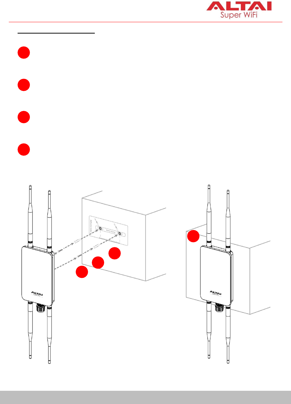
Option 2: Wall Mount
1
Determine where the AP is to be placed and use the adhesive label
to mark location of the two mounting holes on the wall surface.
2
Use an appropriate drill bit to drill two holes, each with 1/3” (8.1mm) in
diameter and 1” (26mm) deep, on the markings.
3
Remove the label. Drive the anchors into the holes and then the
screws into the anchors.
4
Align the mounting slots with the screw heads and attach the AP to
the wall in place.
1
2
3
4
Quick Setup Guide
8
Altai Technologies Ltd. All rights reserved
Power Options and Cable Connection Instructions
You can follow one of the options below for CX200 configuration as
described in the following sections.
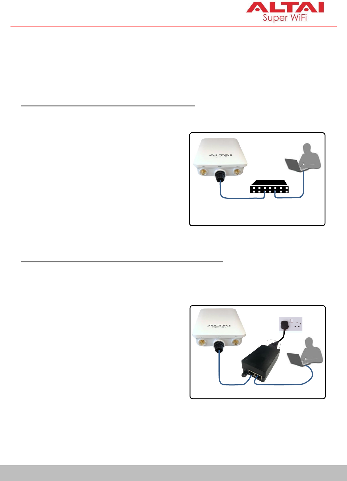
Option 1: 802.3at-Compliant PoE switch
1.
Connect the CX200 Ethernet port
to an 802.3af-compliant PoE
switch with an Ethernet Cable.
2.
Connect a computer to the
switch.
3.
Make sure the Power LED turns into
a solid light for AP configuration.
Option 2: PoE Injector (Purchased separately)
1.
Connect the PoE injector ports as
described below via Ethernet
Cables.
- PoE Port: Go to CX200
- LAN Port: Go to a computer
2.
Conn
ect
t
h
e
Po
E
I
n
jec
t
o
r
t
o
A
C
power socket using a power cord.
3.
Make sure the Power LED turns into
a solid light for AP configuration.
802.3af – Compliant
PoE Switch
PoE
LAN
Po
E
I
n
jec
t
o
r
Quick Setup Guide
9
Altai Technologies Ltd. All rights reserved
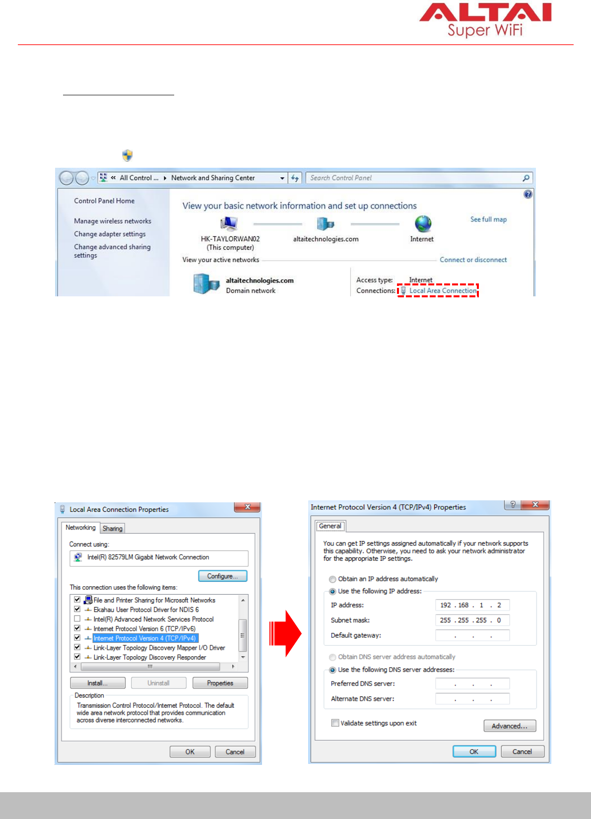
1. Change TCP/IP Setting on Your Computer
For Windows 7/8/10 users,
1.
Go to Control Panel, click Network and Sharing Center and then choose
the adapter that you want to connect to CX200 unit. In this example,
adapter “Local Area Connection” is in connection with CX200. Click it and
then click Properties.
2.
Under the
Networking
tab, click
Internet Protocol Version 4 (TCP/IPv4)
in
the list box “This connection uses the following items”, and then click
Properties.
3.
Type in the following IP address and Subnet mask:
IP address: 192.168.1.2
Subnet mask: 255.255.255.0
4.
Click
OK
to close the
Internet Protocol Version 4 (TCP/IPv4) Properties
dialog box and click OK again to close the Local Area Connection
Properties dialog box.
Quick Setup Guide
10
Altai Technologies Ltd. All rights reserved
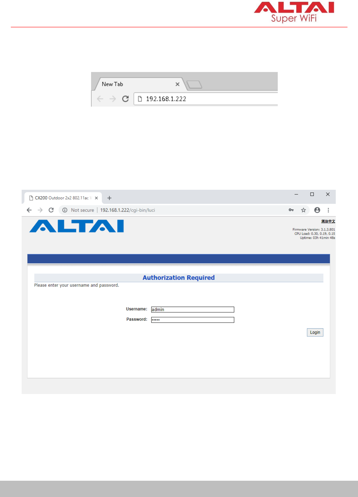
2. Access to Web Interface
1.
Open a web browser. Type 192.168.1.222 in the address bar and then hit
Enter
.
2.
Login page will come up and you are required to enter username and
password. By default, the credentials are:
Username: admin
Password: admin
3.
Click Login.
Quick Setup Guide
11
Altai Technologies Ltd. All rights reserved
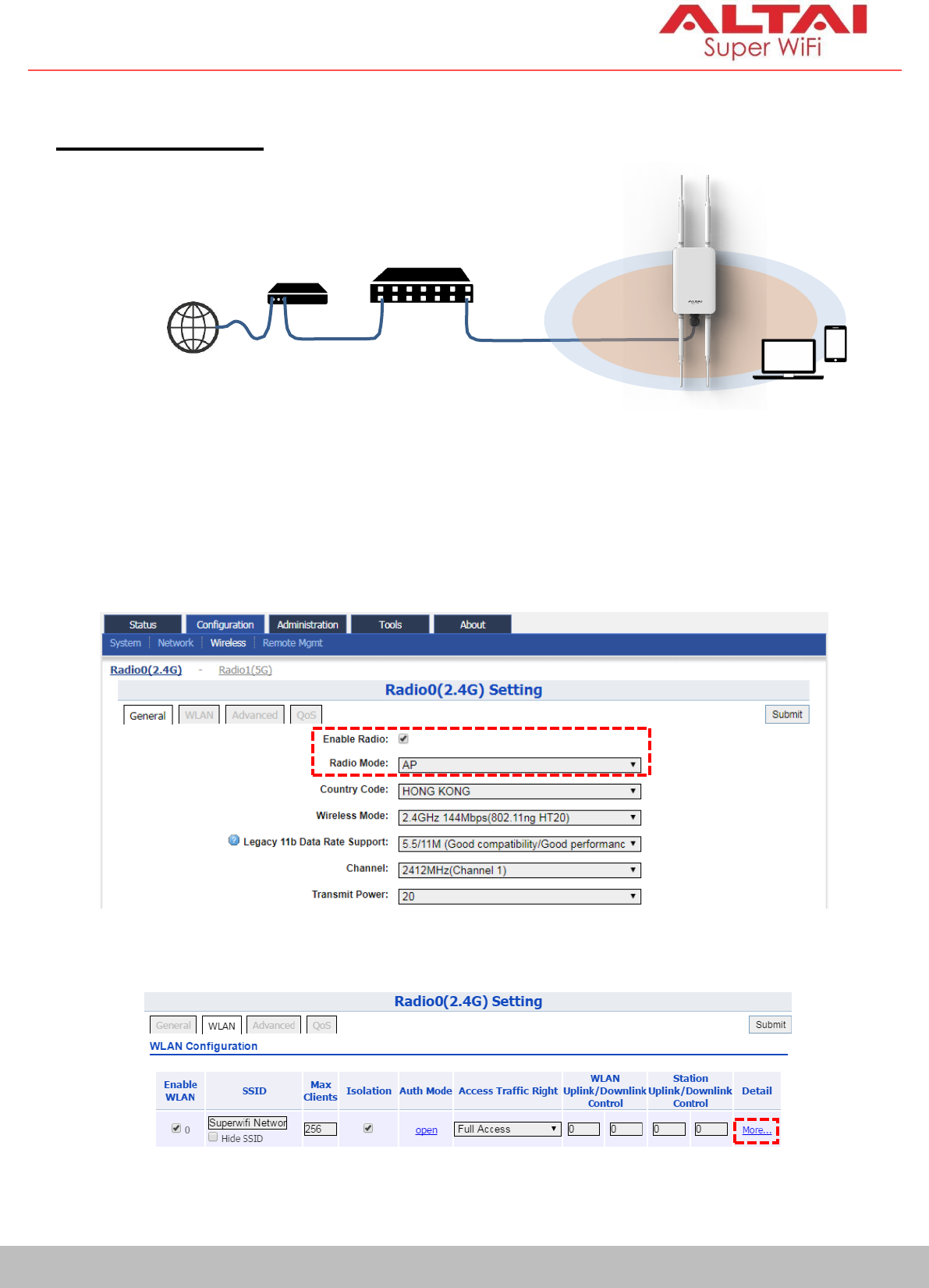
3. Configure AP Mode (2.4G/5G)
Network Scenario
Go to
Configuration
>
Wireless
>
Radio0(2.4G)/Radio1(5G)
>
General
. Below
screenshots show an example for 2.4G radio configuration only. Same
procedures can be applied to 5G radio configuration.
1.
Make sure the box of Enable Radio is checked. Select AP mode for the
field of Radio Mode. Then click Submit.
2.
Click WLAN and click More… in Detail of WLAN 0 to go to another page
for SSID and security configuration.
ISP Gateway/Router
Modem
CX200
(AP Mode)
Internet
2.4G + 5G
Coverage
Modem Ethernet
Ethernet
Cable Cable Cable
Quick Setup Guide
12
Altai Technologies Ltd. All rights reserved
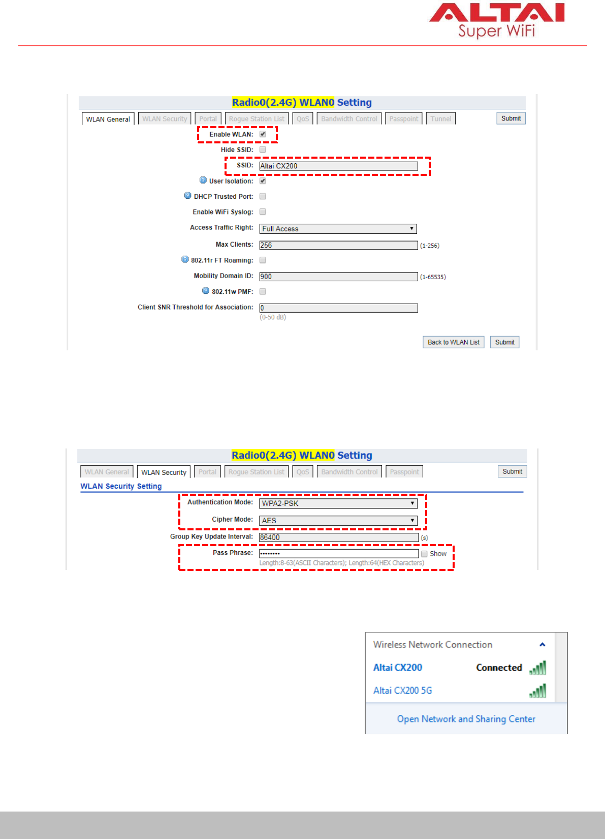
3.
Make sure WLAN is enabled by checking the box. Type in SSID to name
the wireless network you want to broadcast and then click Submit.
4.
Click the tab
WLAN Security
. Select
WPA2-PSK
from the drop down menu
of Authentication Mode and select AES for Cipher Mode. Type in a
password within 8~64 characters or numbers in Pass Phrase and click
Submit.
5.
Click Save & Apply at the top right corner to have all changes take effect.
6.
Hook up the CX200 as shown in Network
Scenario. The SSID should now be
broadcast from CX200 and can be seen in
the computer for wireless connection.
Quick Setup Guide
13
Altai Technologies Ltd. All rights reserved
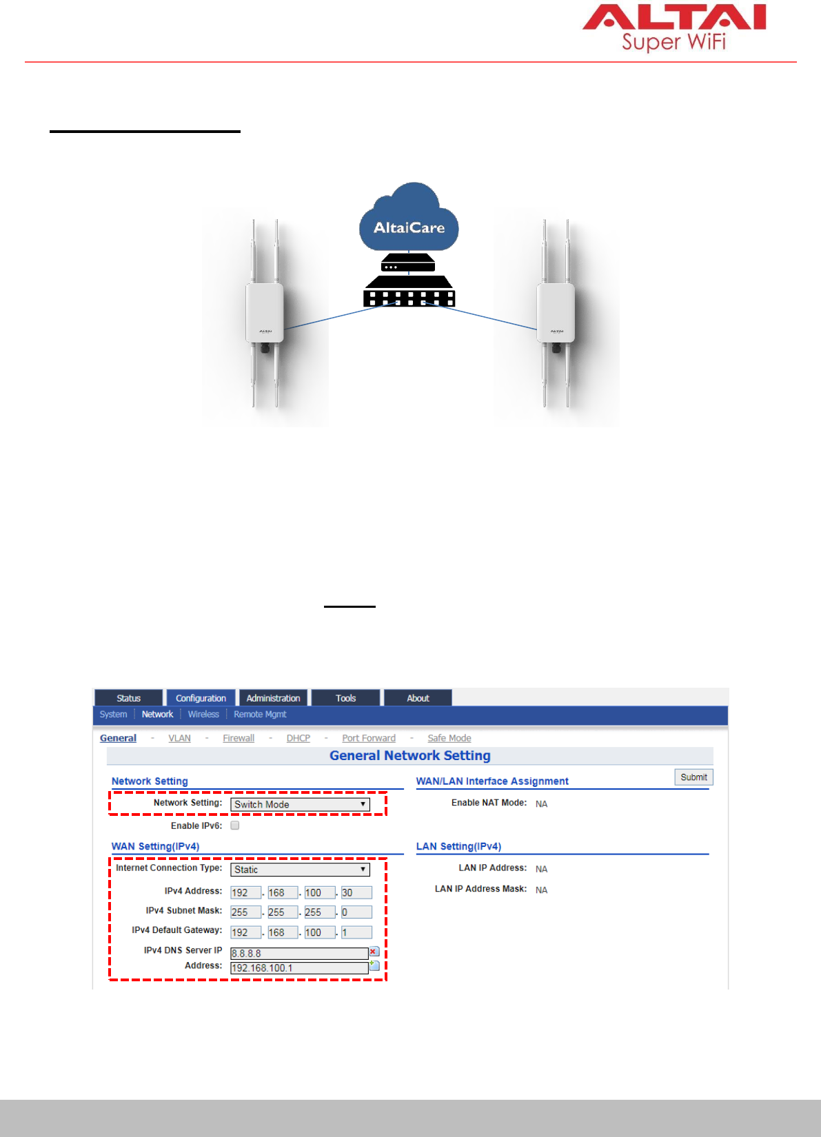
4. Connect with Cloud-Based Controller – AltaiCare
Network Scenario:
1.
You can manage your CX200 and set up hotspot service for the
subscribers with AltaiCare, which is a cloud-based system.
2.
Go to
Configuration
>
Network
>
General
. Select
Switch Mode
for
Network
Setting and make sure the CX200 can reach Internet and communicate
with AltaiCare by inputting valid IP settings either via DHCP or with Static IP
configuration. Google Public DNS Server can be considered, e.g. 8.8.8.8 or
8.8.4.4 if you are not sure about the ISP DNS’s Server IP.
ISP Modem
CX200_1 (AP)
Local Gateway/
Router
CX200_2 (AP)
Quick Setup Guide
14
Altai Technologies Ltd. All rights reserved
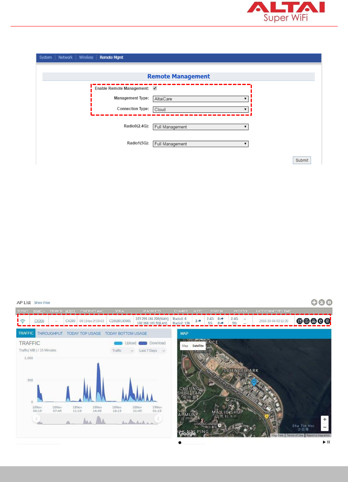
3.
Click Remote Mgmt and check the box of Enable Remote Management.
Select AltaiCare as Management Type and Cloud as Connection Type.
4.
Select Full Management if the device is running in AP Mode. For Station
Mode, Bridge Mode and Repeater Mode, select Monitor Mode instead.
5.
Click Submit and then Save & Apply at the top right corner to make all the
changes take effect.
6.
Follow AltaiCare Quick Start Guide and register the CX200 in the system for
AP management and user service and admission control.
7.
CX200 will appear as online in AltaiCare AP list if the connection is
successful.

Quick Setup Guide
15
Altai Technologies Ltd. All rights reserved
Federal Communication Commission Interference Statement (FCC) – USA
This device complies with Part 15 of the FCC Rules. Operation is subject to the following two
c
on
d
i
ti
on
s
:
(
1)
Th
is
de
vi
c
e
m
ay no
t
c
au
s
e
h
a
r
m
fu
l
i
nter
f
er
enc
e,
an
d
(
2)
th
is
de
v
i
c
e
m
ust
ac
c
e
pt
any interference received, including interference that may cause undesired operation.
This equipment has been tested and found to comply with the limits for a Class B digital device,
pursuant to Part 15 of the FCC Rules. These limits are designed to provide reasonable protection
against harmful interference in a residential installation. This equipment generates, uses and can
radiate radio frequency energy and, if not installed and used in accordance with the instructions,
may cause harmful interference to radio communications. However, there is no guarantee that
interference will not occur in a particular installation. If this equipment does cause harmful
interference to radio or television reception, which can be determined by turning the equipment
off and on, the user is encouraged to try to correct the interference by one of the following
measures:
-
Reorient or relocate the receiving antenna.
-
I
n
c
r
ea
s
e
th
e
s
ep
a
r
at
i
o
n
be
tw
ee
n
th
e
e
qu
i
p
m
ent
and
r
e
c
e
i
ver
.
-
Connect the equipment into an outlet on a circuit different from that
to which the receiver is connected.
-
Consult the dealer or an experienced radio/TV technician for help.
FCC Caution: Any changes or modifications not expressly approved by the party responsible for
compliance could void the user's authority to operate this equipment.
Th
is
tra
n
s
m
i
tt
er
m
ust
n
ot
be
c
o
-l
o
c
at
ed
or
oper
atin
g
i
n
c
on
j
unc
t
i
o
n
w
i
th
any
ot
her
antenna
or
transmitter.
Radiation Exposure Statement:
This equipment complies with FCC radiation exposure limits set forth for an uncontrolled
environment. This equipment should be installed and operated with minimum distance 20cm
between the radiator & your body.

Professional installation instruction
1.
Installation personal
This product is designed for specific application and needs to be installed by a qualified personal
who has RF and related rule knowledge. The general user shall not attempt to install or change
the setting.
2.
Installation location
The product shall be installed at a location where the radiating antenna can be kept 20cm from
nearby person in normal operation condition to meet regulatory RF exposure requirement.
3.
External antenna
Use only the antennas which have been approved by the applicant. The non-approved
antenna(s) may produce unwanted spurious or excessive RF transmitting power which may lead
to the violation of FCC limit and is prohibited.
4.
Installation procedure
Please refer to user’s manual for the detail.
5.
Warning
Please carefully select the installation position and make sure that the final output power does
not exceed the limit set force in relevant rules. The violation of the rule could lead to serious
federal penalty.
European Conformity (CE) – EU
This is a Class B product. In a domestic environment, this product may cause radio interference, in which
case the user may be required to take adequate measures.
16
Quick Setup Guide
Altai Technologies Ltd. All rights reserved

Quick Setup Guide
Warning
Only use the power adaptor supplied with CX200. Using a different power adaptor might damage the
device.
Disclaimer
All specifications are subject to change without prior notice. Altai Technologies assumes no responsibilities
for any inaccuracies in this document or for any obligation to update information in this document. This
document is provided for information purposes only. Altai Technologies reserves the right to change, modify,
transfer, or otherwise revise this publication without notice.
Copyright © 2018 Altai Technologies Limited
ALL RIGHTS RESERVED.
Altai Technologies Limited
Unit 209, 2/F, Lakeside 2,
10 Science Park West Avenue,
Hong Kong Science Park,
Shatin, New Territories,
Hong Kong
Telephone: +852 3758 6000
Fax: +852 2607 4021
Web: www.altaitechnologies.com
Customer Support Centre:
Email: support@altaitechnologies.com
17
Altai Technologies Ltd. All rights reserved