Altai Technologies IX500 IX500 Indoor 2x2 802.11ac Wave 2 AP User Manual AX500 S Quick Setup Guide
Altai Technologies Limited IX500 Indoor 2x2 802.11ac Wave 2 AP AX500 S Quick Setup Guide
User Manual
1
Altai Technologies Ltd. All rights reserved
Quick Setup Guide
ALTAI IX500 Indoor 2x2
802.11ac Wave 2 AP
_________________________________________________
Quick Setup Guide
Version 1.0
2
Altai Technologies Ltd. All rights reserved
Quick Setup Guide
Introduction
Thank you for purchasing the ALTAI IX500 product. This guide provides
instructions to install the product and set it up as AP with minimal effort.
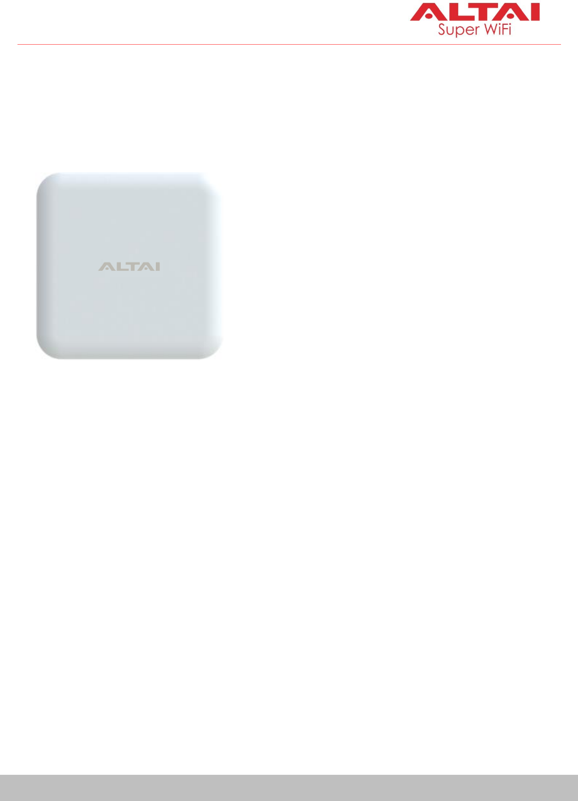
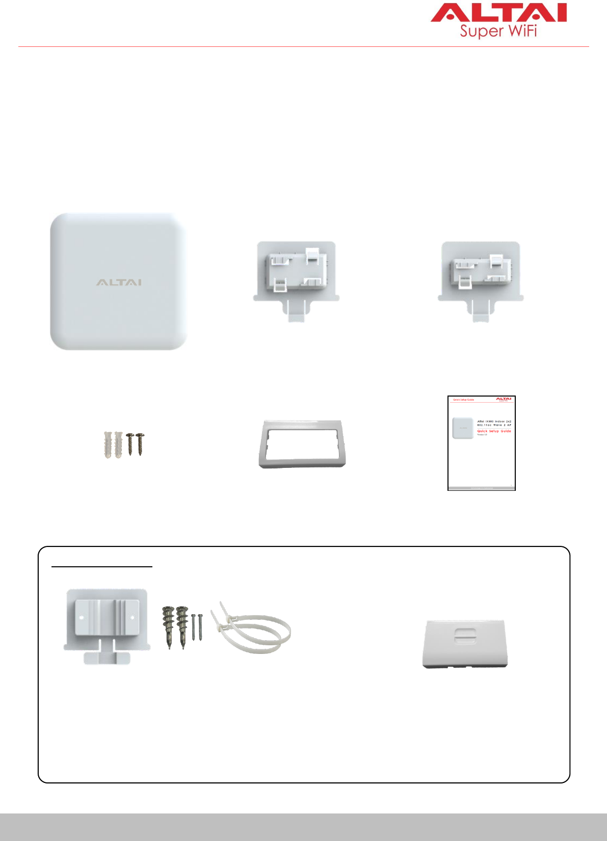
Package Contents
Ceiling Mount Base
(15/16” T-Rail)
Ceiling Mount Base
(9/16” T-Rail)
IX500 Main Unit
Quick Setup Guide
Back Cover
(For Indoor Installation)
Dry Wall Mount Kit
-Anchors x 2
-Screws x 2
Back Cover
(For Outdoor Installation)
Optional Items
Wall/Pole Mount Kit
-Mount Base x 1
-Anchors (For Concrete Wall) x 2
-Screws (For Concrete Wall) x 2
-Cable Tie (For Pole) x 2
3
Altai Technologies Ltd. All rights reserved
Quick Setup Guide
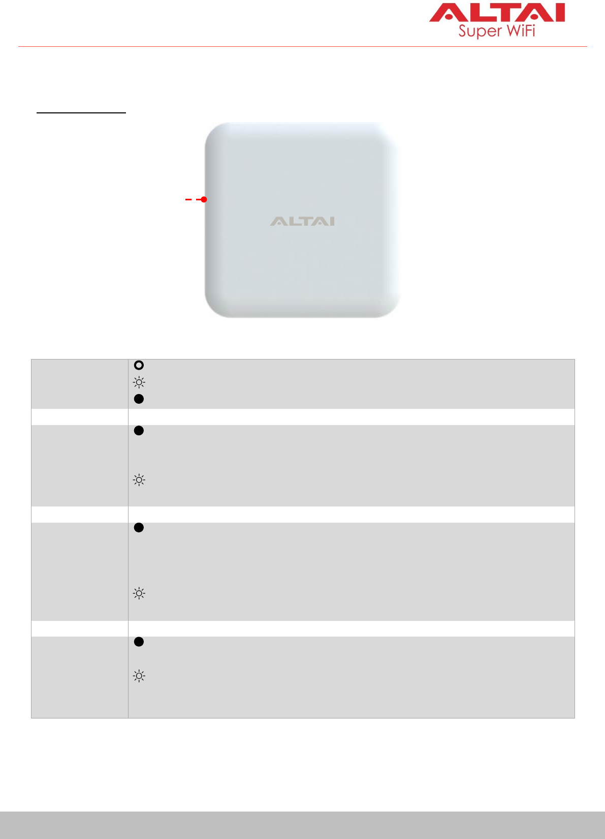
Hardware Overview
LED Indicator
Power/Booting
Status
Off
AP Powered Off
Flashing Red
AP Booting Up
Solid Red
AP Boot Up Finished and Ready for Service
2.4G Radio
Enabled Only
(AP/Station/
Repeater)
Solid Purple
1. AP Mode on but with no Client Association; OR
2. Station Mode on but not connected to Remote AP; OR
3. Repeater Mode on but not connected to Remote AP
Alternate Flashing
Purple & Red
Data Transmitting/Receiving
5G Radio
Enabled Only
(AP/Station/
Repeater/Bridge)
Solid Yellow
1. AP Mode on but with no Client Association; OR
2. Station Mode on but not connected to Remote AP; OR
3. Repeater Mode on but not connected to Remote AP; OR
4. Bridge Mode on but not connected to Remote Peer
Alternate Flashing
Yellow & Red
Data Transmitting/Receiving
2.4G and 5G
Radios Enabled
(AP/Station/
Repeater/Bridge)
Solid White
AP/Station/Repeater/Bridge Mode on but with no
connection with Client/Remote AP/Remote Peer
Alternate Flashing
Purple, Yellow & Red
Data Transmitting/Receiving
LED Indicator
4
Altai Technologies Ltd. All rights reserved
Quick Setup Guide
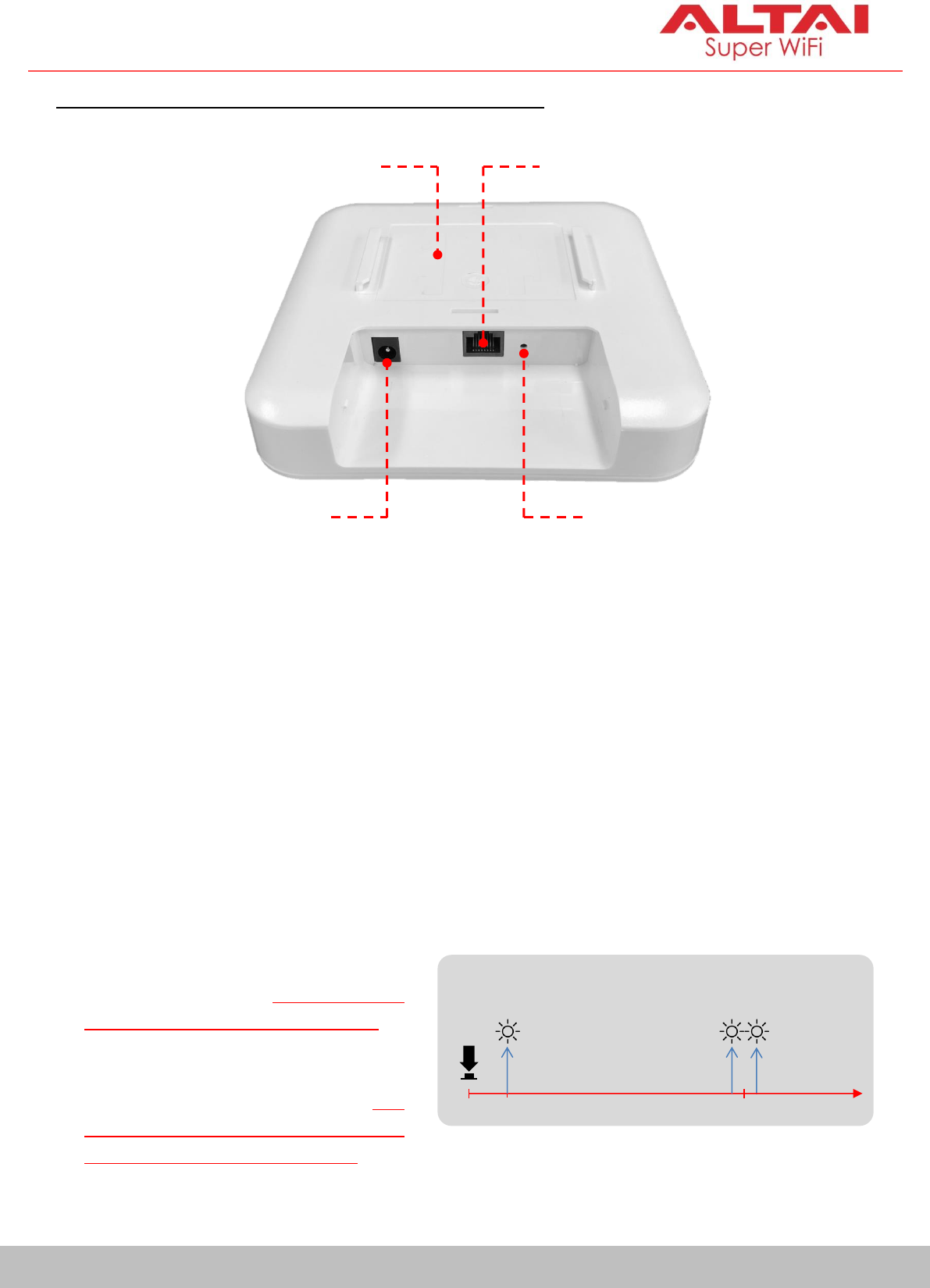
Ethernet Port, DC Power Jack and Reset Button
Ethernet Port:
It is used to connect to power source (see the Power Options in the later
section) and provides 10/100/1000 Mbps network interface for LAN
connection.
DC Power Jack:
It is used to connect to DC power source of 12VDC/1A as another power
option.
Reset Button:
Ethernet Port
Reset Button
DC Power
Jack
Mount
Base Slot
Red LED Indicator
0s
1-2s
5-8s
Factory Reset
Reboot
It serves two functions:
Reboot: Press and hold the
Reset Button for 2-3 seconds
until the red LED blinks once.
Factory Reset: Press and hold
the Reset Button for 5-8
seconds until the red LED
blinks twice consecutively.
5
Altai Technologies Ltd. All rights reserved
Quick Setup Guide
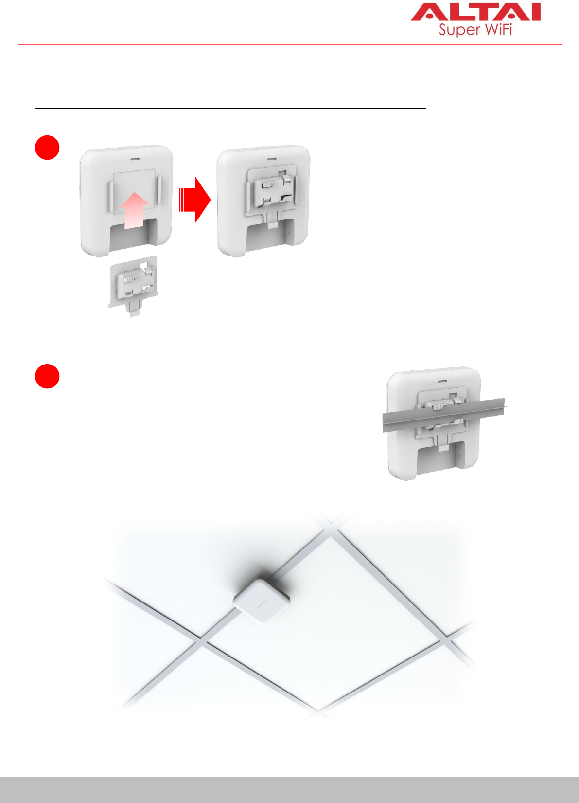
Mounting Options
Option 1: T-Rail Ceiling Mount (9/16” T-Rail OR 15/16” T-Rail)
2
Insert an appropriately sized ceiling rail
into one of the mount base slots first. Then
turn the AP slightly so that the rail slips into
another slot to lock the AP into place.
1
Select an appropriate ceiling
mount base (9/16” or 15/16”)
and slide the base into the
slot of the AP.
6
Altai Technologies Ltd. All rights reserved
Quick Setup Guide
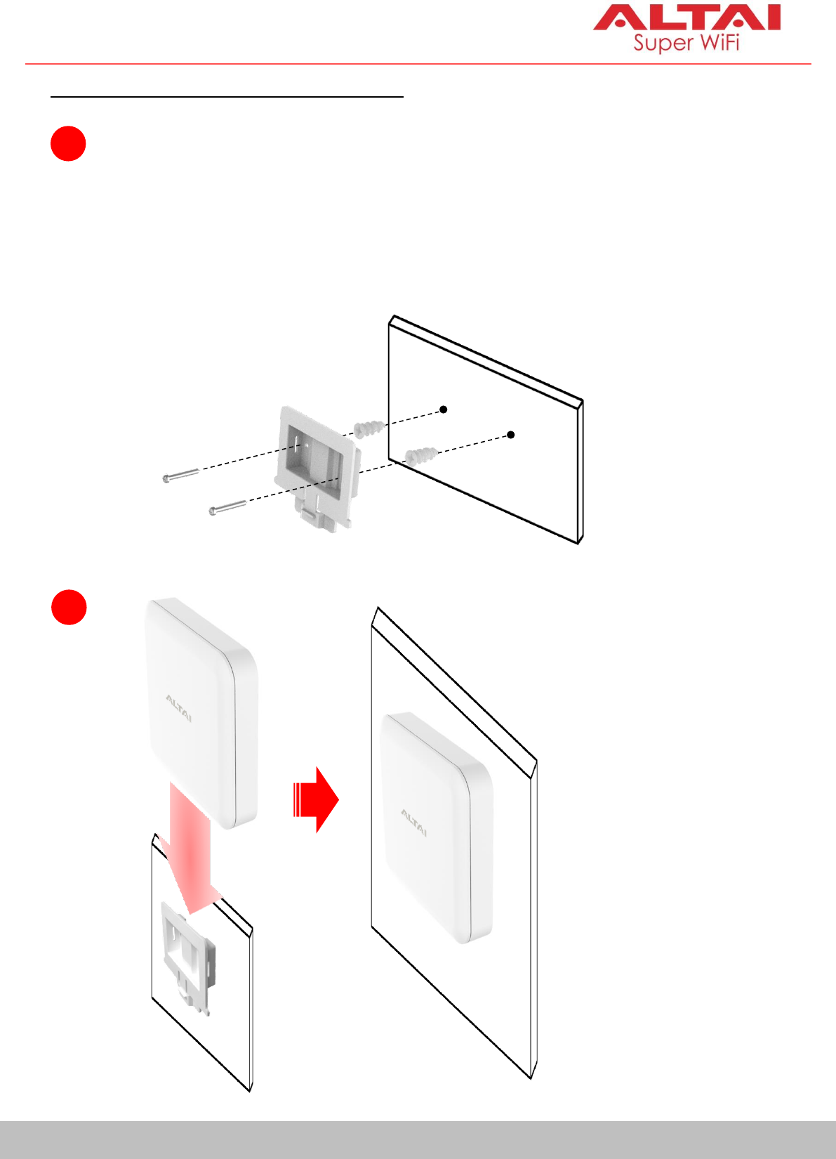
Option 2: Wall Mount (Concrete Wall)
1
Determine where the AP is to be placed and mark location on the
wall surface for the two mounting holes of the mount base. Use an
appropriate drill bit to drill holes of 1/3” (8.1mm) diameter and 1”
(26mm) deep. Screw the anchors into the holes and then insert the
screws through the mount base to the anchors to attach the base to
the wall.
2
Slide the base into the
slot of the AP.
7
Altai Technologies Ltd. All rights reserved
Quick Setup Guide
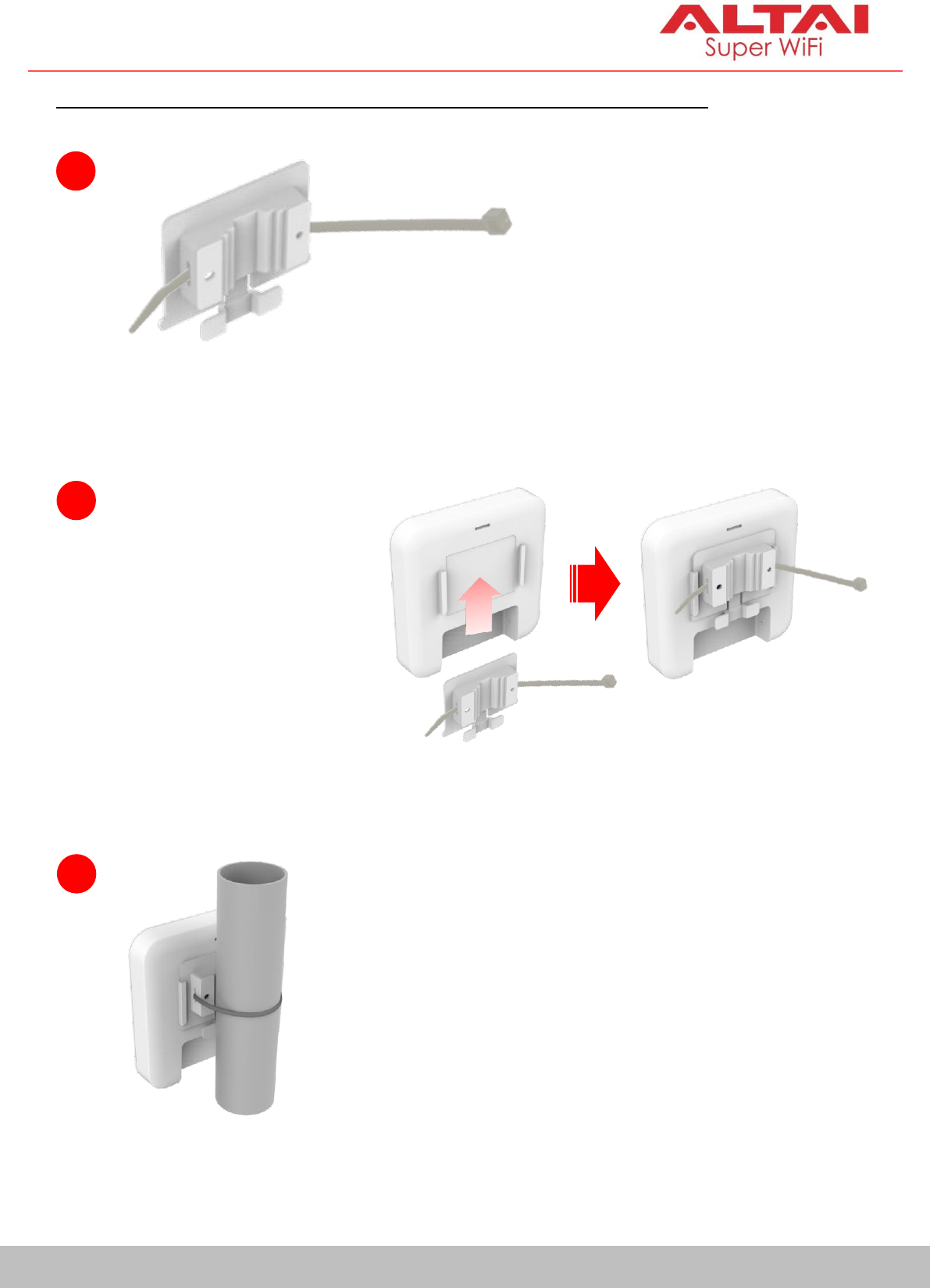
Option 3: Pole Mount (For 1 inch to 3 inches of pole diameter)
1
Thread the open end of the
cable tie through the two
slots of the mount base.
2
Slide the base into
the slot of the AP.
3
Determine where the AP is to be placed. Tighten
the cable tie to secure the base to the pole.
8
Altai Technologies Ltd. All rights reserved
Quick Setup Guide
Setup Requirements and Preparation
A computer with Web Browser: Google Chrome, Mozilla Firefox, or
Microsoft Internet Explorer 8 (or above)
Two Cat 5e/6 Ethernet cables
802af/at-compliant PoE switch (54Vdc/0.6A)
AltaiCare account (Optional) for cloud AP management and user service
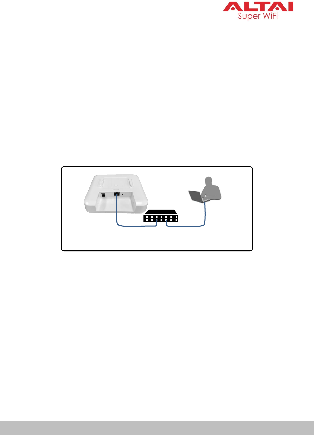
Power Options and Cable Connection Instructions
1. Connect the IX500 Ethernet port to an 802.3af/802.at-compliant PoE switch
with an Ethernet Cable.
2. Connect a computer to the switch.
3. Make sure the LED indicator turns into a solid light for AP configuration.
802.3af/802.at – Compliant
PoE Switch
IX500 AP
Ethernet Cable
(PoE + Data)
Ethernet Cable
(Data)
9
Altai Technologies Ltd. All rights reserved
Quick Setup Guide
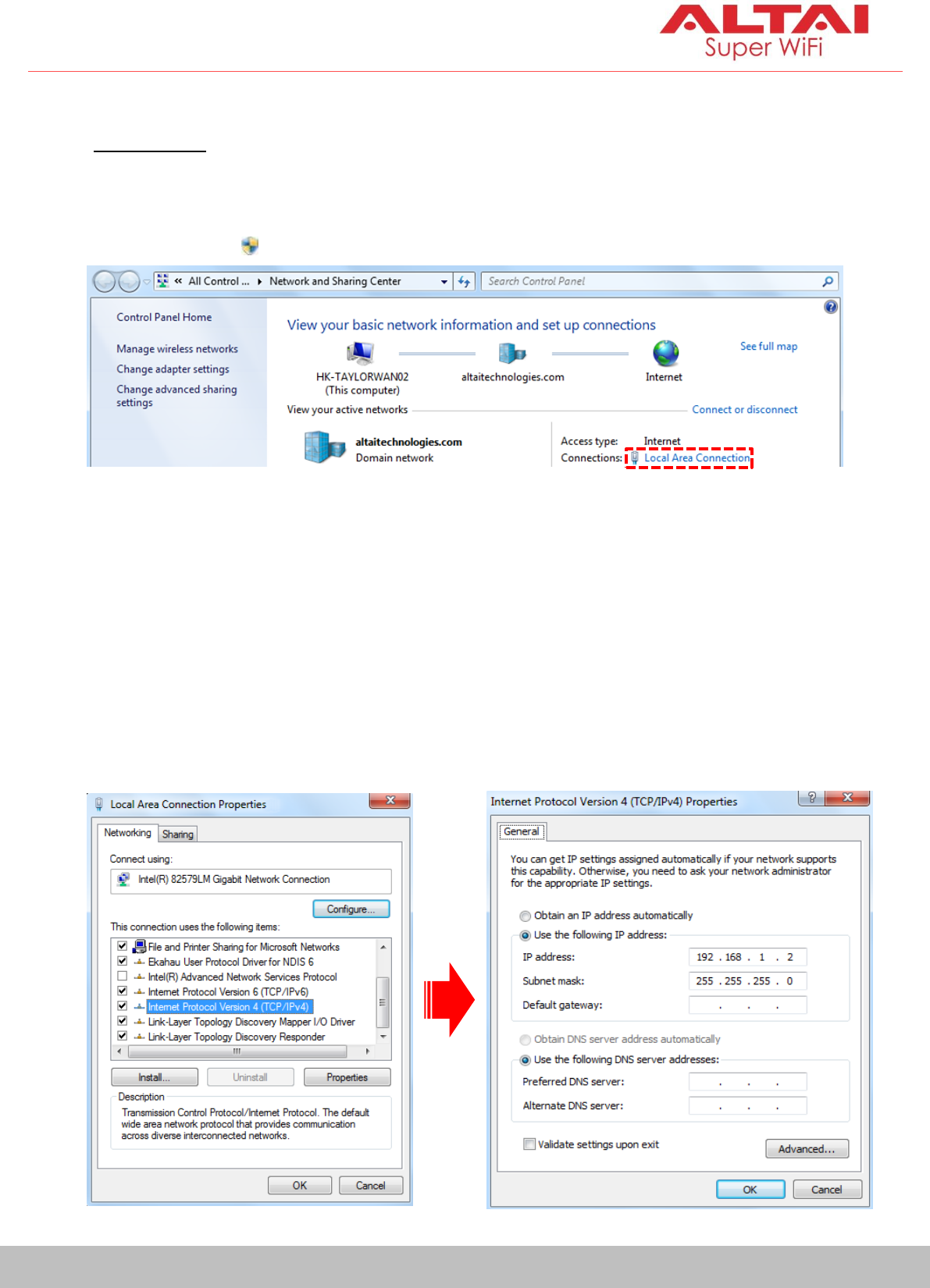
1. Change TCP/IP Setting on Your Computer
For Windows 7 users,
1. Go to Control Panel, click Network and Sharing Center and then choose
the adapter that you want to connect to IX500 unit. In this example,
adapter “Local Area Connection” is in connection with IX500-S. Click it
and then click Properties.
2. Under the Networking tab, click Internet Protocol Version 4 (TCP/IPv4) in
the list box “This connection uses the following items”, and then click
Properties.
3. Type in the following IP address and Subnet mask:
IP address: 192.168.1.2
Subnet mask: 255.255.255.0
4. Click OK to close the Internet Protocol Version 4 (TCP/IP) Properties dialog
box and click OK again to close the Local Area Connection Properties
dialog box.
10
Altai Technologies Ltd. All rights reserved
Quick Setup Guide
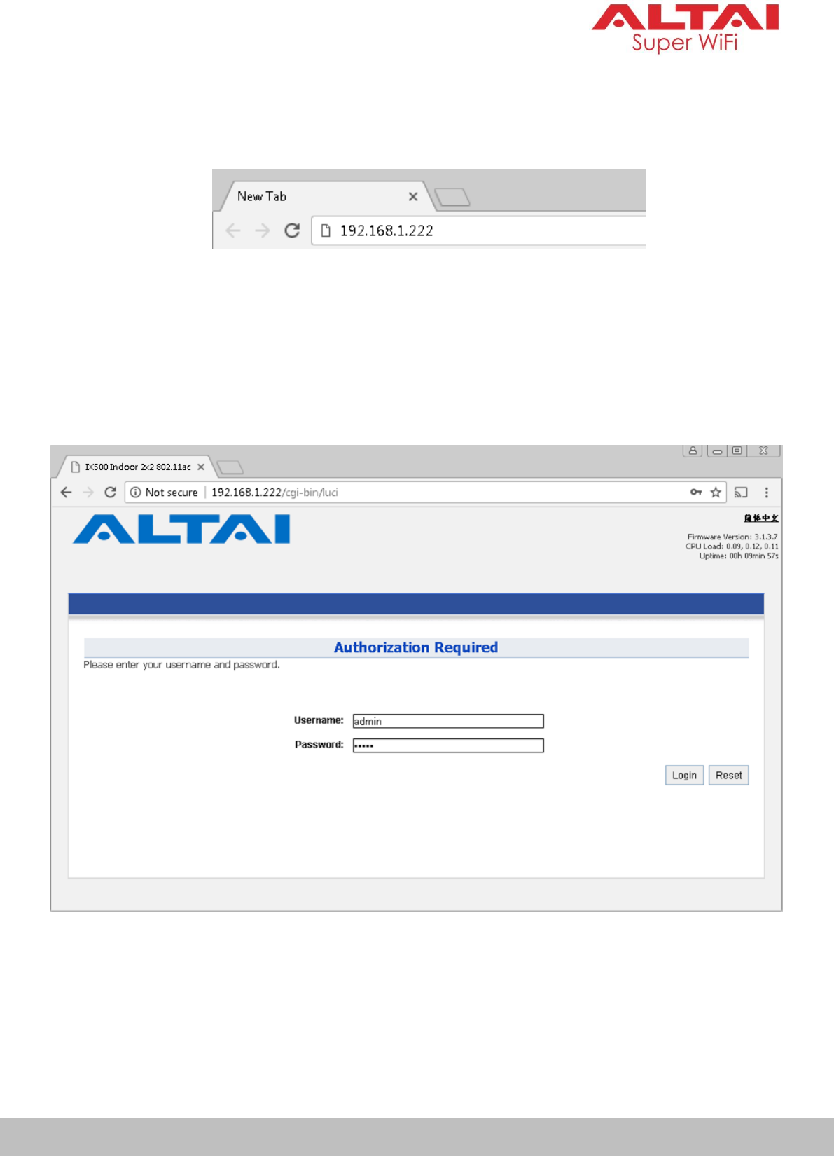
2. Access to Web Interface
1. Open a web browser. Type 192.168.1.222 in the address bar and then hit
Enter.
2. Login page will come up and you are required to enter username and
password. By default, the credentials are:
Username: admin
Password: admin
3. Click Login.
11
Altai Technologies Ltd. All rights reserved
Quick Setup Guide
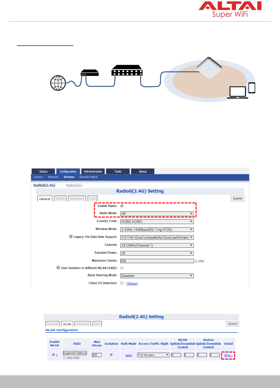
3. Configure AP Mode (2.4G/5G)
Network Scenario
Go to Configuration > Wireless > Radio0(2.4G)/Radio1(5G) > General. Below
screenshots show an example for 2.4G radio configuration only. Same
procedures can be applied to 5G radio configuration.
1. Make sure the box of Enable Radio is checked. Select AP mode for the
field of Radio Mode. Then click Submit.
2. Click WLAN and click More… in Detail of WLAN 0 to go to another page
for SSID and security configuration.
Internet
ISP
Modem
Ethernet
Cable
Gateway/Router
Modem
Cable
Ethernet
Cable
2.4G + 5G
Coverage
IX500
(AP Mode)
12
Altai Technologies Ltd. All rights reserved
Quick Setup Guide
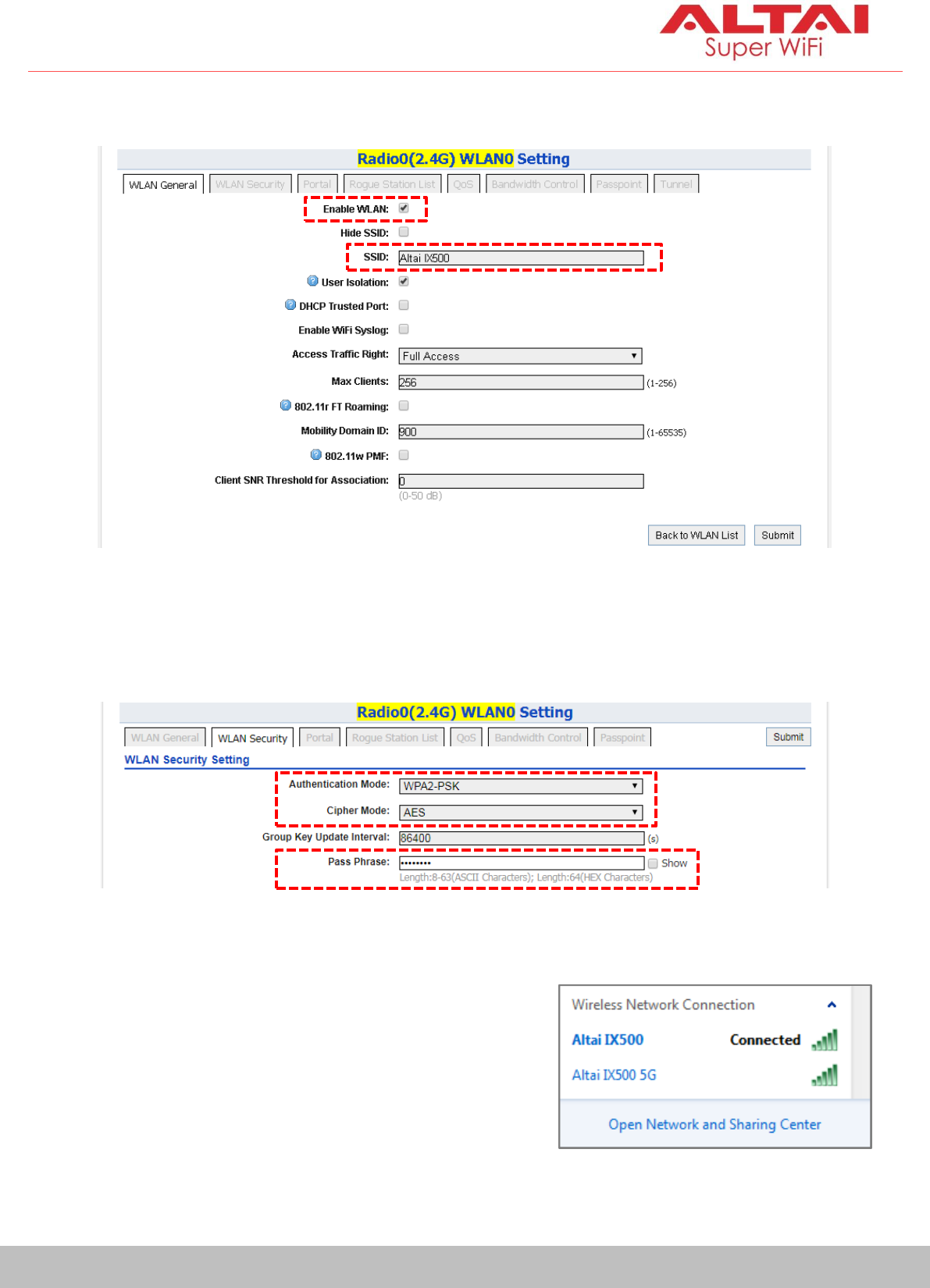
3. Make sure WLAN is enabled by checking the box. Type in SSID to name
the wireless network you want to broadcast and then click Submit.
4. Click the tab WLAN Security. Select WPA2-PSK from the drop down menu
of Authentication Mode and select AES for Cipher Mode. Type in a
password within 8~64 characters or numbers in Pass Phrase and click
Submit.
5. Click Save & Apply at the top right corner to have all changes take effect.
6. Hook up the IX500 as shown in Network
Scenario. The SSID should now be
broadcast from IX500 and can be seen in
the computer for wireless connection.
13
Altai Technologies Ltd. All rights reserved
Quick Setup Guide
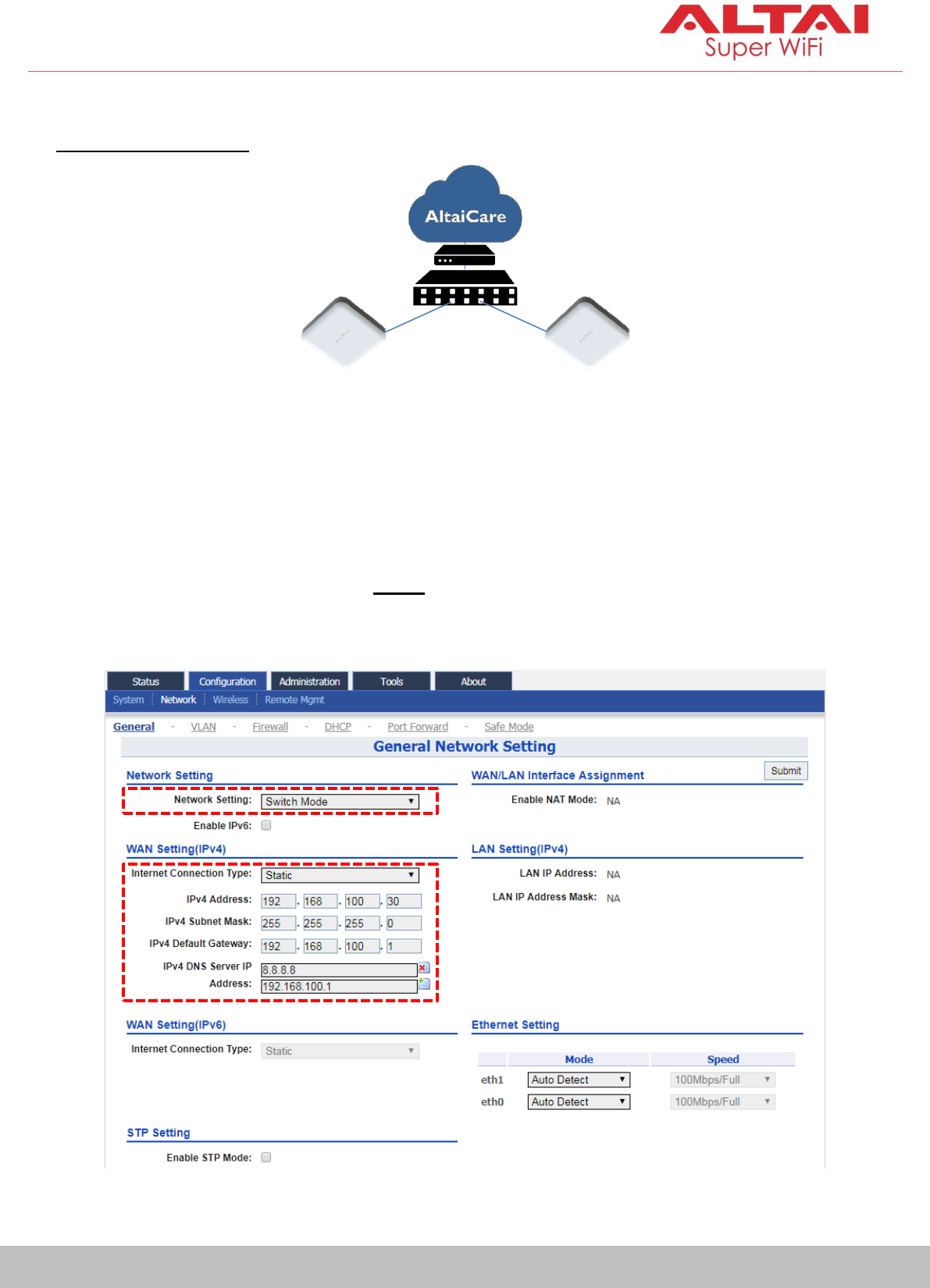
4. Connect with Cloud-Based Controller – AltaiCare
Network Scenario:
1. You can manage your IX500 and set up hotspot service for the subscribers
with AltaiCare, which is a cloud-based system.
2. Go to Configuration > Network > General. Select Switch Mode for Network
Setting and make sure the IX500 can reach Internet and communicate
with AltaiCare by inputting valid IP settings either via DHCP or with Static IP
configuration. Google Public DNS Server can be considered, e.g. 8.8.8.8 or
8.8.4.4 if you are not sure about the ISP DNS’s Server IP.
IX500_1 (AP)
IX500_2 (AP)
ISP Modem
Local Gateway/
Router
14
Altai Technologies Ltd. All rights reserved
Quick Setup Guide
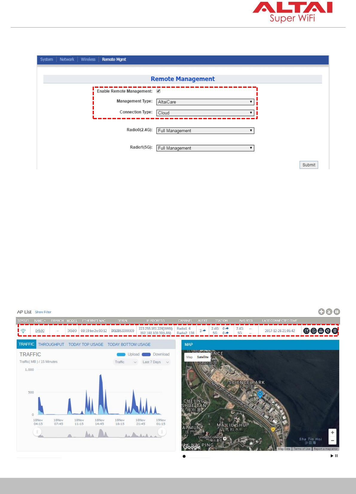
3. Click Remote Mgmt and check the box of Enable Remote Management.
Select AltaiCare as Management Type and Cloud as Connection Type.
4. Select Full Management if the device is running in AP Mode. For Station
Mode, Bridge Mode and Repeater Mode, select Monitor Mode instead.
5. Click Submit and then Save & Apply at the top right corner to make all the
changes take effect.
6. Follow AltaiCare Quick Start Guide and register the IX500 in the system for
AP management and user service and admission control.
7. IX500 will appear as online in AltaiCare AP list if the connection is
successful.

15
Altai Technologies Ltd. All rights reserved
Quick Setup Guide
Federal Communication Commission Interference Statement (FCC) – USA
This equipment has been tested and found to comply with the limits for a Class B digital device, pursuant to
Part 15 of the FCC Rules. These limits are designed to provide reasonable protection against harmful
interference in a residential installation. This equipment generates, uses and can radiate radio frequency
energy and, if not installed and used in accordance with the instructions, may cause harmful interference
to radio communications. However, there is no guarantee that interference will not occur in a particular
installation. If this equipment does cause harmful interference to radio or television reception, which can be
determined by turning the equipment off and on, the user is encouraged to try to correct the interference
by one of the following measures:
• Reorient or relocate the receiving antenna.
• Increase the separation between the equipment and receiver.
• Connect the equipment into an outlet on a circuit different from that to which the receiver is
connected.
• Consult the dealer or an experienced radio/TV technician for help.
FCC Caution: Any changes or modifications not expressly approved by the party responsible for
compliance could void the user's authority to operate this equipment.
This device complies with Part 15 of the FCC Rules. Operation is subject to the following two conditions: (1)
This device may not cause harmful interference, and (2) this device must accept any interference received,
including interference that may cause undesired operation.
IMPORTANT NOTE:
FCC Radiation Exposure Statement:
This equipment complies with FCC radiation exposure limits set forth for an uncontrolled environment. This
equipment should be installed and operated with minimum distance 20cm between the radiator & your
body.
European Conformity (CE) – EU
This is a Class B product. In a domestic environment, this product may cause radio interference, in which
case the user may be required to take adequate measures.