Altai Technologies WA3311NAC-E Altai A3-Ei Dual-band 3X3 802.11ac WiFi AP User Manual Lightning Protection

Altai Technologies Limited Altai A3-Ei Dual-band 3X3 802.11ac WiFi AP Lightning Protection

Contents

Users Manual - Installation
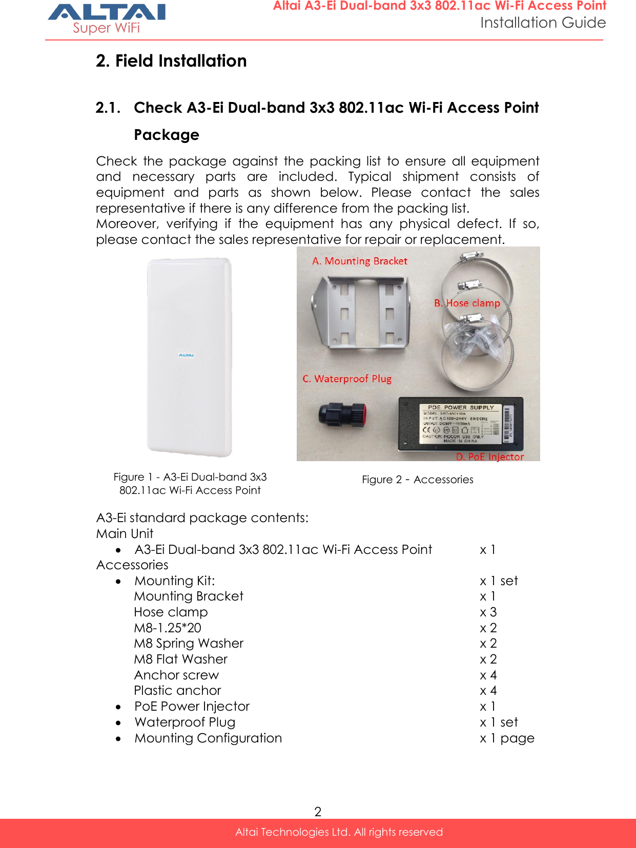
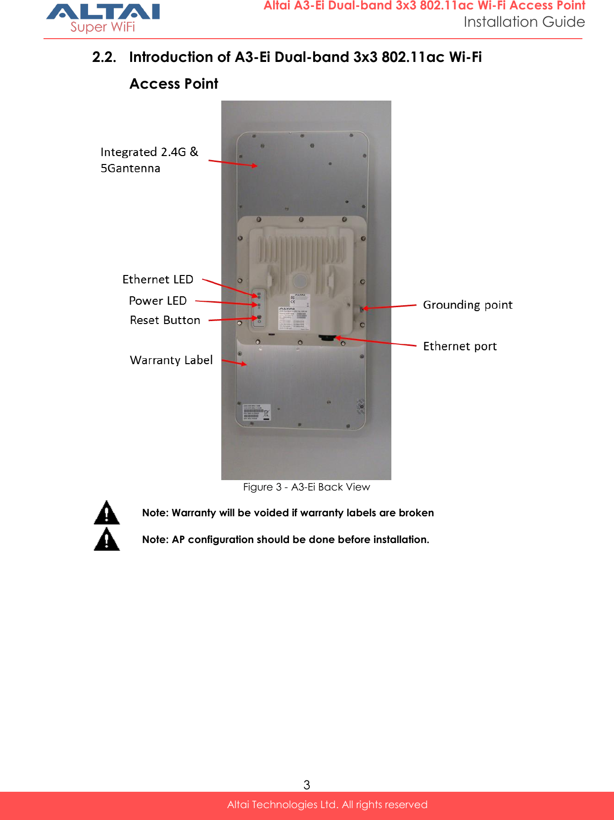
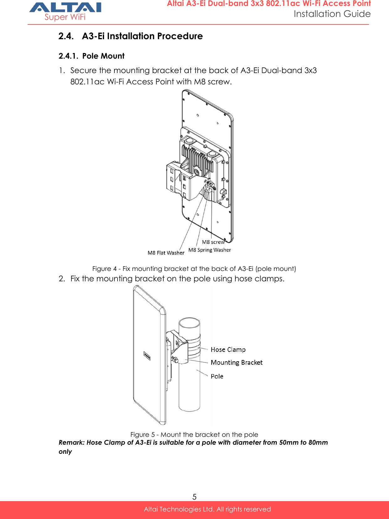
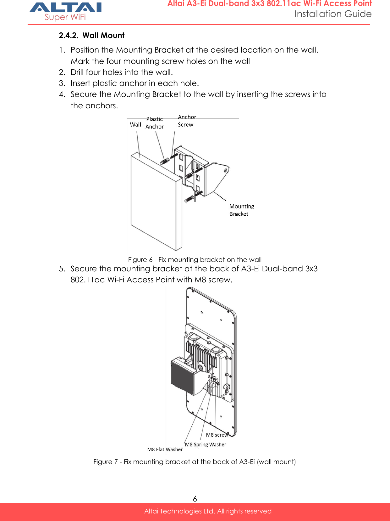
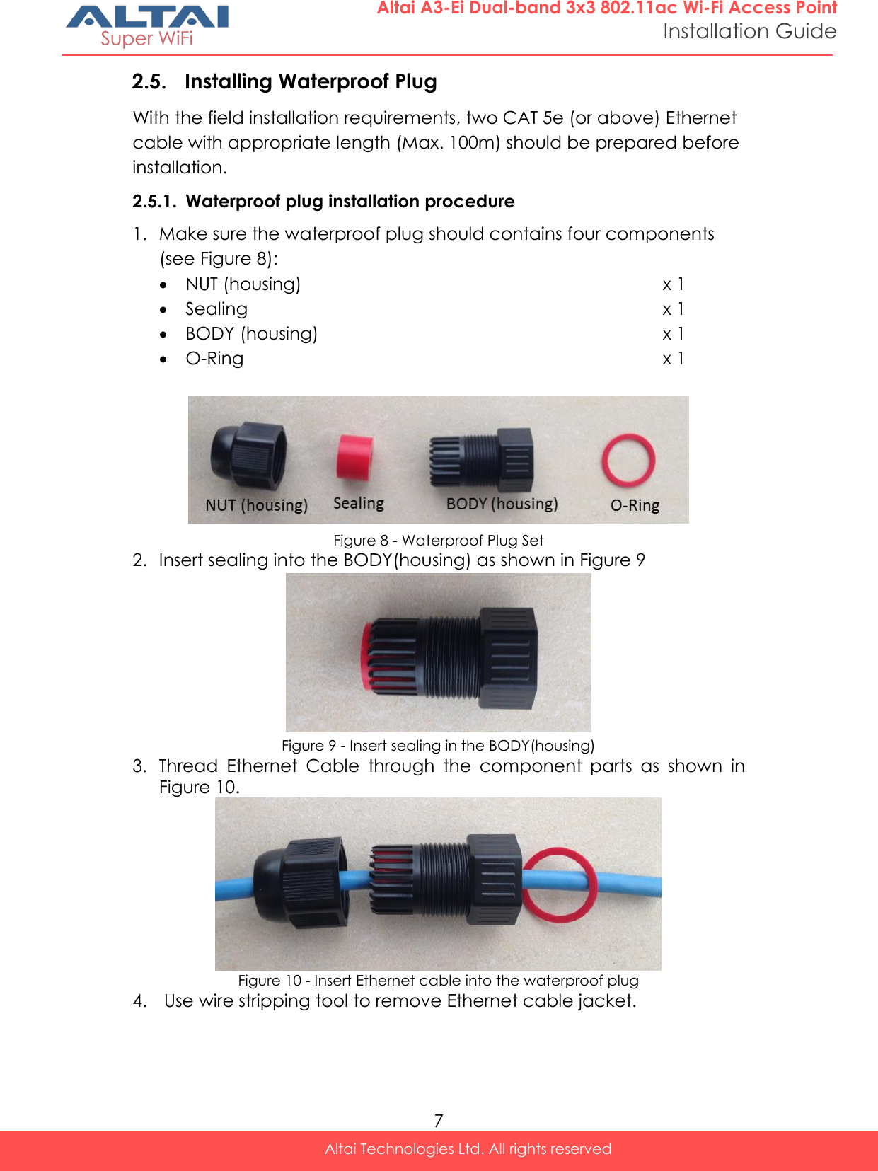
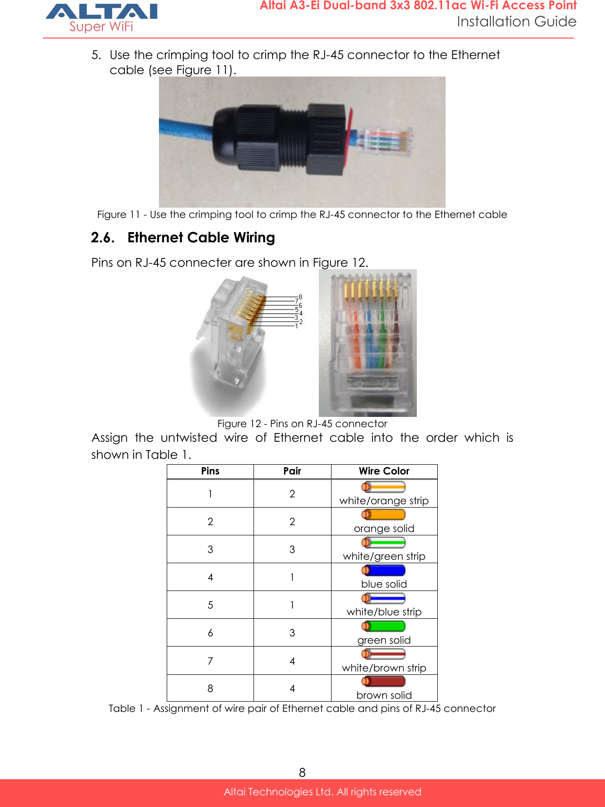
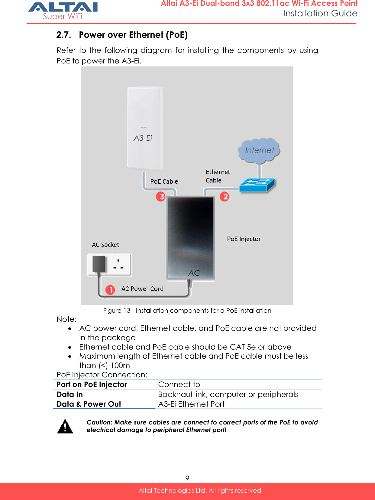
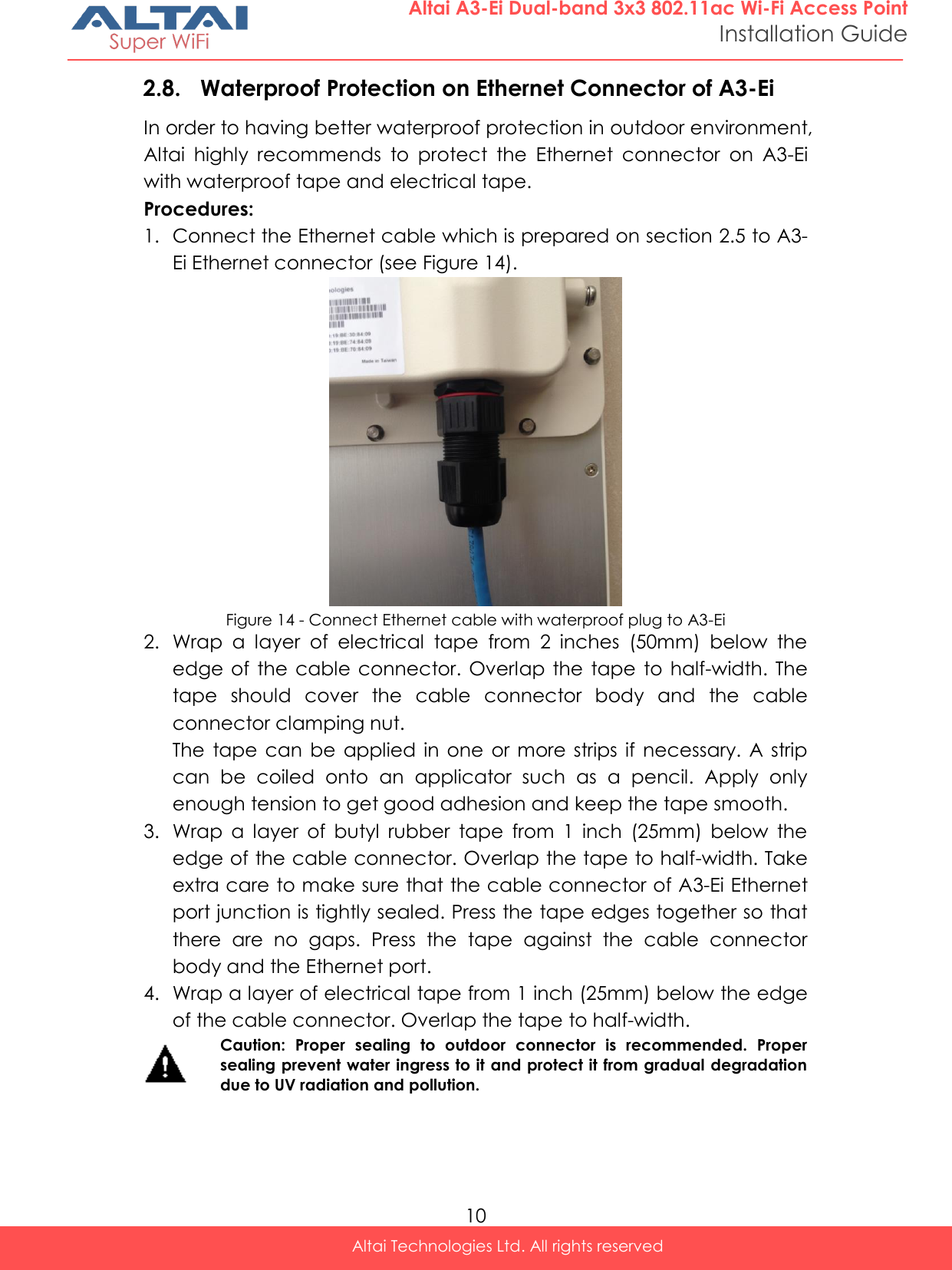
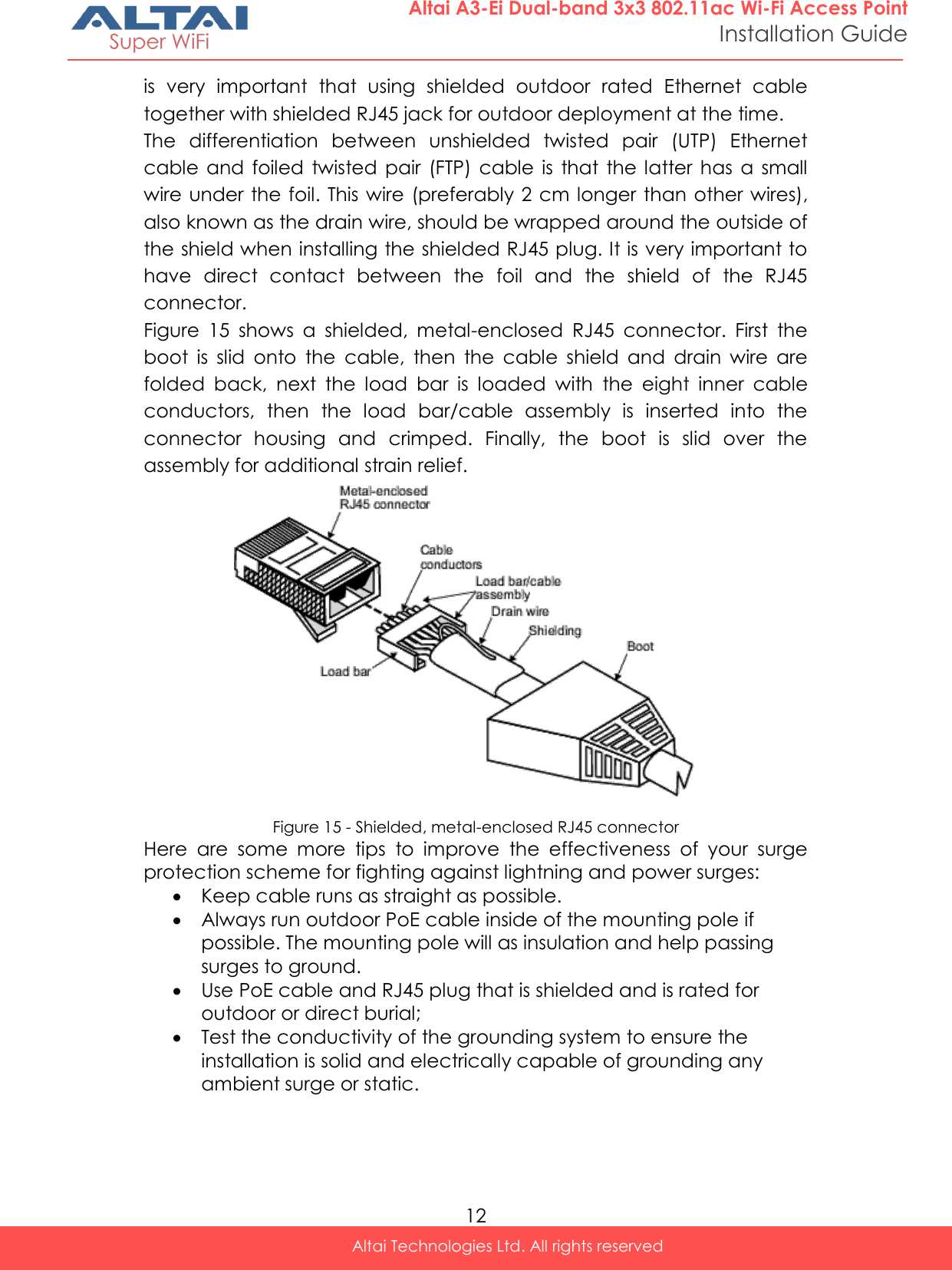
   Altai Technologies Ltd. All rights reserved       Installation Guide Version 1.1  Altai A3-Ei Dual-band 3x3 802.11ac  Wi-Fi Access Point      Copyright © 2015 Altai Technologies Limited  ALL RIGHTS RESERVED.
 ii Altai Technologies Ltd. All rights reserved  Altai A3-Ei Dual-band 3x3 802.11ac Wi-Fi Access Point Installation Guide Altai Technologies Limited Unit 209, 2/F, Lakeside 2,  10 Science Park West Avenue,  Hong Kong Science Park,  Shatin, New Territories,  Hong Kong  Telephone: +852 3758 6000 Fax: +852 2607 4021 Web: www.altaitechnologies.com  Customer Support Centre:  Email: support@altaitechnologies.com
 iii Altai Technologies Ltd. All rights reserved  Altai A3-Ei Dual-band 3x3 802.11ac Wi-Fi Access Point Installation Guide
 iv Altai Technologies Ltd. All rights reserved  Altai A3-Ei Dual-band 3x3 802.11ac Wi-Fi Access Point Installation Guide Radio Frequency Interference Requirements  This device complies with Part 15 of FCC Rules.  Operation is subject to the following conditions: 1. This device may not cause harmful interference. 2. This  device  must  accept  any  interference  received,  including interference that may cause undesired operation. 3. This device should not be co-located or operating in conjunction with any other antenna or transmitter.  Interference Statement  This equipment has been tested and found to comply with the limits for a  Class  B  digital  device,  pursuant  to  Part  15  of  the  FCC  Rules;  these limits  are  designed  to  provide  reasonable  protection  against  harmful interference in a residential installation. This equipment generates uses and can radiate radio frequency energy and, if not installed and used in accordance with the instructions, may cause harmful interference to radio communications.  However,  there  is  no  guarantee  that  interference  will  not  occur  in  a particular installation. If this equipment does cause harmful interference to  radio  or  television  reception,  which  can  be  determined  by  turning the equipment off and on, the user is encouraged to try to correct the interference by one of the following measures:  Reorient or relocate the receiving antenna.  Increase the separation between the equipment and receiver.  Connect the equipment into an outlet on a circuit different from that to which the receiver is connected.  Consult  the  dealer  or  an  experienced  radio/TV  technician  for help.  FCC  Caution:  To  assure  continued  compliance,  (example  –  use  only shielded interface cables when connecting to computer or peripheral devices). Any changes or modifications not expressly approved by the party  responsible  for  compliance  could  void  the  user’s  authority  to operate this equipment.
 v Altai Technologies Ltd. All rights reserved  Altai A3-Ei Dual-band 3x3 802.11ac Wi-Fi Access Point Installation Guide Warning  The user is advised to keep apart from the base-station and antenna with at least 45cm when the base-station is in operation.  Please install a lightning arrestor to protect the base station for lightning dissipation during rainstorms. Lightning arrestors are mounted outside the structure and must be grounded by means of a ground wire to the nearest ground rod or item that is grounded.  A3-Ei requires professional installation. The installer is responsible for ensuring that the 5GHz radio is used exclusively for fixed, point-to-point operations.  Disclaimer  All  specifications  are  subject  to  change  without  prior  notice.  Altai Technologies  assumes  no  responsibilities  for  any  inaccuracies  in  this document  or  for  any  obligation  to  update  information  in  this document.  This  document  is  provided  for  information  purposes  only. Altai  Technologies  reserves  the  right  to  change,  modify,  transfer,  or otherwise revise this publication without notice.
 vi Altai Technologies Ltd. All rights reserved  Altai A3-Ei Dual-band 3x3 802.11ac Wi-Fi Access Point Installation Guide Table of contents  1. INTRODUCTION ...........................................................................................1 2. FIELD INSTALLATION ....................................................................................2 2.1. CHECK A3-EI DUAL-BAND 3X3 802.11AC WI-FI ACCESS POINT PACKAGE .................... 2 2.2. INTRODUCTION OF A3-EI DUAL-BAND 3X3 802.11AC WI-FI ACCESS POINT .................. 3 2.3. PREPARATION OF A3-EI INSTALLATION .................................................................... 4 2.4. A3-EI INSTALLATION PROCEDURE ........................................................................... 5 2.4.1. Pole Mount ................................................................................................ 5 2.4.2. Wall Mount ................................................................................................ 6 2.5. INSTALLING WATERPROOF PLUG ............................................................................ 7 2.5.1. Waterproof plug installation procedure .................................................... 7 2.6. ETHERNET CABLE WIRING ..................................................................................... 8 2.7. POWER OVER ETHERNET (POE) .............................................................................. 9 2.8. WATERPROOF PROTECTION ON ETHERNET CONNECTOR OF A3-EI .............................. 10 3. GROUNDING PROTECTION ...................................................................... 11 4. SURGE PROTECTION .................................................................................. 11 5. ELECTROSTATIC DISCHARGE (ESD) PROTECTION .................................. 13 6. POST INSTALLATION PROCEDURES .......................................................... 13 7. LED COLORS AND WHAT THEY MEAN ..................................................... 14 8. ACCESSING A3-EI ADMINISTRATION WEB INTERFACE (WEB UI) .......... 15 8.1. PREPARING THE ADMINISTRATIVE COMPUTER ......................................................... 15 8.2. LOGIN WEB UI ................................................................................................. 16 8.3. SECONDARY IP ADDRESS OF A3-EI ....................................................................... 16 9. RESTORING FACTORY DEFAULT SETTING ................................................. 17 10. TYPICAL A3-EI SETUP ............................................................................. 18
 1 Altai Technologies Ltd. All rights reserved  Altai A3-Ei Dual-band 3x3 802.11ac Wi-Fi Access Point Installation Guide 1. Introduction This  document  is  written  to  provide  the  necessary  information  for installing  Altai A3-Ei  Dual-band  3x3 802.11ac  Wi-Fi  Access  Point  (A3-Ei) on field location. This  document  is  applicable  for  hardware  platform  with  the  following models:  Product name: A3-Ei Dual-band 3x3 802.11ac Wi-Fi Access Point Model number: WA3311NAC-E  It  is  assumed  that  site  survey  has  been  performed.  Appropriate antenna  pole  and  AP  locations  have  been  selected.  It  is  highly recommended  that  cable  lengths  of  various  cables  are  confirmed. Good  site  installation  plan  should  consist  of  site  map,  drawing illustrating AP and poles locations, antenna bearing/down-tilt, antenna height, and network topology. User  may  refer  the  following  documents  during  A3-Ei  installation  and configuration on necessary. [1] A3  Series  Dual-band  3x3  802.11ac  Wi-Fi  Access  Point Configuration Guide [2] A3-Ei Dual-band 3x3 802.11ac Wi-Fi Access Point Data Sheet
 2 Altai Technologies Ltd. All rights reserved  Altai A3-Ei Dual-band 3x3 802.11ac Wi-Fi Access Point Installation Guide 2. Field Installation 2.1. Check A3-Ei Dual-band 3x3 802.11ac Wi-Fi Access Point Package Check  the  package  against  the  packing  list  to  ensure  all  equipment and  necessary  parts  are  included.  Typical  shipment  consists  of equipment  and  parts  as  shown  below.  Please  contact  the  sales representative if there is any difference from the packing list. Moreover,  verifying  if  the  equipment  has  any  physical  defect.  If  so, please contact the sales representative for repair or replacement.   Figure 1 - A3-Ei Dual-band 3x3 802.11ac Wi-Fi Access Point Figure 2 - Accessories  A3-Ei standard package contents: Main Unit  A3-Ei Dual-band 3x3 802.11ac Wi-Fi Access Point x 1 Accessories  Mounting Kit: x 1 set Mounting Bracket x 1 Hose clamp x 3 M8-1.25*20 x 2 M8 Spring Washer x 2 M8 Flat Washer x 2 Anchor screw x 4 Plastic anchor x 4  PoE Power Injector x 1  Waterproof Plug x 1 set  Mounting Configuration x 1 page
 3 Altai Technologies Ltd. All rights reserved  Altai A3-Ei Dual-band 3x3 802.11ac Wi-Fi Access Point Installation Guide 2.2. Introduction of A3-Ei Dual-band 3x3 802.11ac Wi-Fi Access Point  Figure 3 - A3-Ei Back View   Note: Warranty will be voided if warranty labels are broken  Note: AP configuration should be done before installation.
 4 Altai Technologies Ltd. All rights reserved  Altai A3-Ei Dual-band 3x3 802.11ac Wi-Fi Access Point Installation Guide 2.3. Preparation of A3-Ei Installation Before installation, please prepare the following tools and accessories: Tools:  Drill with M6 drill bit (for wall mount only)  Screw Driver  Adjustable Wrench  Hammer (for wall mount only)  Wire Stripping Tool and Crimping Tool  Waterproof Tape and   Electrical Tape Accessories  Ground Wire x 1  Ethernet cable x 2
 5 Altai Technologies Ltd. All rights reserved  Altai A3-Ei Dual-band 3x3 802.11ac Wi-Fi Access Point Installation Guide 2.4. A3-Ei Installation Procedure 2.4.1. Pole Mount 1. Secure the mounting bracket at the back of A3-Ei Dual-band 3x3 802.11ac Wi-Fi Access Point with M8 screw.  Figure 4 - Fix mounting bracket at the back of A3-Ei (pole mount) 2. Fix the mounting bracket on the pole using hose clamps.  Figure 5 - Mount the bracket on the pole Remark: Hose Clamp of A3-Ei is suitable for a pole with diameter from 50mm to 80mm only
 6 Altai Technologies Ltd. All rights reserved  Altai A3-Ei Dual-band 3x3 802.11ac Wi-Fi Access Point Installation Guide 2.4.2. Wall Mount 1. Position the Mounting Bracket at the desired location on the wall. Mark the four mounting screw holes on the wall 2. Drill four holes into the wall.  3. Insert plastic anchor in each hole. 4. Secure the Mounting Bracket to the wall by inserting the screws into the anchors.  Figure 6 - Fix mounting bracket on the wall 5. Secure the mounting bracket at the back of A3-Ei Dual-band 3x3 802.11ac Wi-Fi Access Point with M8 screw.  Figure 7 - Fix mounting bracket at the back of A3-Ei (wall mount)
 7 Altai Technologies Ltd. All rights reserved  Altai A3-Ei Dual-band 3x3 802.11ac Wi-Fi Access Point Installation Guide 2.5. Installing Waterproof Plug With the field installation requirements, two CAT 5e (or above) Ethernet cable with appropriate length (Max. 100m) should be prepared before installation. 2.5.1. Waterproof plug installation procedure 1. Make sure the waterproof plug should contains four components (see Figure 8):  NUT (housing) x 1  Sealing x 1  BODY (housing) x 1  O-Ring x 1   Figure 8 - Waterproof Plug Set 2. Insert sealing into the BODY(housing) as shown in Figure 9  Figure 9 - Insert sealing in the BODY(housing) 3. Thread  Ethernet  Cable  through  the  component  parts  as  shown  in Figure 10.  Figure 10 - Insert Ethernet cable into the waterproof plug 4.  Use wire stripping tool to remove Ethernet cable jacket.
 8 Altai Technologies Ltd. All rights reserved  Altai A3-Ei Dual-band 3x3 802.11ac Wi-Fi Access Point Installation Guide 5. Use the crimping tool to crimp the RJ-45 connector to the Ethernet cable (see Figure 11).  Figure 11 - Use the crimping tool to crimp the RJ-45 connector to the Ethernet cable 2.6. Ethernet Cable Wiring Pins on RJ-45 connecter are shown in Figure 12.  Figure 12 - Pins on RJ-45 connector Assign  the  untwisted  wire  of  Ethernet  cable  into  the  order  which  is shown in Table 1. Pins Pair Wire Color 1 2  white/orange strip 2 2  orange solid 3 3  white/green strip 4 1  blue solid 5 1  white/blue strip 6 3  green solid 7 4  white/brown strip 8 4  brown solid Table 1 - Assignment of wire pair of Ethernet cable and pins of RJ-45 connector
 9 Altai Technologies Ltd. All rights reserved  Altai A3-Ei Dual-band 3x3 802.11ac Wi-Fi Access Point Installation Guide 2.7. Power over Ethernet (PoE) Refer  to  the  following  diagram  for  installing  the  components  by  using PoE to power the A3-Ei.  Figure 13 - Installation components for a PoE installation Note:  AC power cord, Ethernet cable, and PoE cable are not provided in the package  Ethernet cable and PoE cable should be CAT 5e or above  Maximum length of Ethernet cable and PoE cable must be less than (<) 100m PoE Injector Connection: Port on PoE Injector Connect to Data In Backhaul link, computer or peripherals Data & Power Out A3-Ei Ethernet Port   Caution: Make sure cables are connect to correct ports of the PoE to avoid electrical damage to peripheral Ethernet port!
 10 Altai Technologies Ltd. All rights reserved  Altai A3-Ei Dual-band 3x3 802.11ac Wi-Fi Access Point Installation Guide 2.8. Waterproof Protection on Ethernet Connector of A3-Ei In order to having better waterproof protection in outdoor environment, Altai  highly  recommends  to  protect  the  Ethernet  connector  on  A3-Ei with waterproof tape and electrical tape. Procedures: 1. Connect the Ethernet cable which is prepared on section 2.5 to A3-Ei Ethernet connector (see Figure 14).  Figure 14 - Connect Ethernet cable with waterproof plug to A3-Ei 2. Wrap  a  layer  of  electrical  tape  from  2  inches  (50mm)  below  the edge  of  the cable connector. Overlap  the  tape  to  half-width. The tape  should  cover  the  cable  connector  body  and  the  cable connector clamping nut. The  tape  can  be applied  in one  or more  strips  if  necessary.  A strip can  be  coiled  onto  an  applicator  such  as  a  pencil.  Apply  only enough tension to get good adhesion and keep the tape smooth. 3. Wrap  a  layer  of  butyl  rubber  tape  from  1  inch  (25mm)  below  the edge of the cable connector. Overlap the tape to half-width. Take extra care to make sure that the cable connector of A3-Ei Ethernet port junction is tightly sealed. Press the tape edges together so that there  are  no  gaps.  Press  the  tape  against  the  cable  connector body and the Ethernet port. 4. Wrap a layer of electrical tape from 1 inch (25mm) below the edge of the cable connector. Overlap the tape to half-width.  Caution:  Proper  sealing  to  outdoor  connector  is  recommended.  Proper sealing prevent water ingress to it and protect it from gradual degradation due to UV radiation and pollution.
 11 Altai Technologies Ltd. All rights reserved  Altai A3-Ei Dual-band 3x3 802.11ac Wi-Fi Access Point Installation Guide 3. Grounding Protection It is essential to properly ground all equipment to prevent the A3-Ei from the  electrical  damage  and  possible  electric  hazer  due  to non-proper power  grounding.  Failure  to  do  so  may  result  in  equipment  damage, injury  or  death.  Product  warranty  does  not cover  damage  resulting  in part or in whole from improper grounding.  An external grounding wire must  be  installed,  especially  when  A3-Ei  is  deployed  on  a  non-metal pole  or  the  metal  pole  is  not  properly  grounded.  Please  consult  your location’s  building  and  electrical  codes  and  follow  them,  or  consult standards such as National Electric Code. Use a 10 AWG grounding wire to connect to the ground connector of the  A3-Ei  by  screw  driver.  Secure  the  grounding  screw  tight  and  the strap connects to the ground. It is recommended that the A3-Ei Dual-band 3x3 802.11ac Wi-Fi Access Point  should  be  installed  with  lightning  rod  to  avoid  any  potential electrical damage and to be connected with the ground node to the existing  ground.  Proper  grounding  will  always  be  the  safety consideration for the A3-Ei Dual-band 3x3 802.11ac Wi-Fi Access Point.  Note: Grounding kits are not provided in the package  4. Surge Protection Type of  Ethernet cable  in  outdoor  deployment  is  critical.  The  Ethernet cable should be either CAT 5e or CAT 6, outdoor rated, and shielded. Specifically,  the  following  types  of  Ethernet  cable  should  be  used  for outdoor  installation:  screened  fully  shielded  twisted  pair  (sFTP)  cable, foiled twisted pair (FTP) cable, or shielded twisted pair (STP) cable. UTP  Ethernet  cable  and/or  unshielded  RJ-45  jack  are  not recommended  in  outdoor  deployment  due  to  increasing electromagnetic  noise  level.  Furthermore,  using  shielded  Ethernet cable with unshielded RJ45 jack between the A3-Ei and PoE injector is not recommended. Improperly grounded STP Ethernet cable acts as a magnet  for  static  surges  presented  in  the  environment.  Since  the charges discharged improperly, it couples with the data lines or power lines  of  the  PoE  cable.  As  a  result,  the  coupling  high  voltages  which presents on the PoE cable may damage the access point. Therefore, it
 12 Altai Technologies Ltd. All rights reserved  Altai A3-Ei Dual-band 3x3 802.11ac Wi-Fi Access Point Installation Guide is  very  important  that  using  shielded  outdoor  rated  Ethernet  cable together with shielded RJ45 jack for outdoor deployment at the time. The  differentiation  between  unshielded  twisted  pair  (UTP)  Ethernet cable  and  foiled  twisted  pair  (FTP)  cable  is  that  the  latter has  a  small wire under the foil. This wire (preferably 2 cm longer than other wires), also known as the drain wire, should be wrapped around the outside of the shield when installing the shielded RJ45 plug. It is very important to have  direct  contact  between  the  foil  and  the  shield  of  the  RJ45 connector. Figure  15  shows  a  shielded,  metal-enclosed  RJ45  connector.  First  the boot  is  slid  onto  the  cable,  then  the  cable  shield  and  drain  wire  are folded  back,  next  the  load  bar  is  loaded  with  the  eight  inner  cable conductors,  then  the  load  bar/cable  assembly  is  inserted  into  the connector  housing  and  crimped.  Finally,  the  boot  is  slid  over  the assembly for additional strain relief.  Figure 15 - Shielded, metal-enclosed RJ45 connector Here  are  some  more  tips  to  improve  the  effectiveness  of  your  surge protection scheme for fighting against lightning and power surges:  Keep cable runs as straight as possible.  Always run outdoor PoE cable inside of the mounting pole if possible. The mounting pole will as insulation and help passing surges to ground.  Use PoE cable and RJ45 plug that is shielded and is rated for outdoor or direct burial;  Test the conductivity of the grounding system to ensure the installation is solid and electrically capable of grounding any ambient surge or static.
 13 Altai Technologies Ltd. All rights reserved  Altai A3-Ei Dual-band 3x3 802.11ac Wi-Fi Access Point Installation Guide 5. Electrostatic Discharge (ESD) Protection Electrostatic discharge (ESD) can damage electronic components and cause  latent  damage  that  results  in  premature  failure  even  if components  remain  functional.  In  addition,  the  equipment  must  be properly  grounded.  Technicians  should  always  wear  proper  ESD grounding  straps  connected  to  the  ESD  connector  during  equipment installation, maintenance and repairs. 6. Post Installation Procedures Make  sure  that  all  cables  are  connected  properly  with  the  following procedures  after  completing  the  A3-Ei  installation  and  aligning  the antenna:  Make sure the antenna is mounted tightly after the alignment  Make  sure  the  grounding  strap  is  connected  properly  to  the ground.  Check  all  cables  are  connected  to  PoE  injector  correctly  and properly. o Make  sure  the  Ethernet  cable  from  PC  or  backhaul network equipment is connected to “Data In” port of PoE injector. o Make  sure  the  Ethernet  cable  from  A3-Ei  is  connected  to “Data & Power Out” port of PoE injector.  Make sure the PoE injector’s light is on.  Make sure the right cables are used during the installation  Make  sure  all  connectors  are  sealed  with  the  waterproof  seal properly. After  going  through  the  above  procedure,  it  is  necessary  to  test  the wireless  quality  and  check  whether  the  RSSI  fails  into  the  acceptable range or not via A3-Ei Web UI.  It might be needed to re-aligns antenna again if the performance is not acceptable.
 14 Altai Technologies Ltd. All rights reserved  Altai A3-Ei Dual-band 3x3 802.11ac Wi-Fi Access Point Installation Guide 7. LED Colors and What They Mean LED Mode LED Status (Color) Meaning Power LED Thick AP Off Power off Blinking slowly (Orange) Booting Solid (Orange) Operating Thin AP Off Power off Blinking slowly (Orange) Booting Blinking slowly (Green) Discovery / Connect to Access Controller Solid (Green) Connect to Access Controller successfully and operating Ethernet LED -- Off Link Down 100Mbps Solid (Green) Link Up Blinking (Green) Activity 1000Mbps Solid (Blue) Link Up Blinking (Blue) Activity Remarks: 1. All LED will be off once pressing down the reset button 2. Pressing and holding the reset button until Power LED blinks once, the device reboots. 3. Pressing and holding the reset button until Power LED blinks twice consecutively, the device restores the factory default setting. Table 2 –A3-Ei operation LED indicators
 15 Altai Technologies Ltd. All rights reserved  Altai A3-Ei Dual-band 3x3 802.11ac Wi-Fi Access Point Installation Guide 8. Accessing  A3-Ei  Administration  Web  Interface (Web UI)  8.1. Preparing the Administrative Computer 1. On your Windows XP or Windows 7 computer, open the Network Connections (or Change adapter settings) control panel according to how the Start menu is set up:  On Windows XP, click Start > Control Panel > Network Connections. On Windows 7, click Start > Control Panel > Network and Internet > Network and Sharing Center > Change adapter settings.  2. Right-click the icon for Local Area Connection, and then click Properties. 3. When the Local Area Connection Properties dialog box appears, select Internet Protocol (TCP/IP) (or Internet Protocol Version 4 (TCP/IPv4)) from the scrolling list, and then click Properties. The Internet Protocol (TCP/IP) Properties dialog box appears. 4. Write down all of the currently active network settings. You will need this information later when you restore your computer to its current network configuration. 5. Configure the IP address settings with the values listed in Table 3.  IP Address Any address in the 192.168.1.x, except 192.168.1.222 and 192.168.1.255 Example: 192.168.1.2 Subnet Mask 255.255.255.0 Default Gateway Blank DNS Blank Table 3 - Configure administrative computer’s IP address settings 6. Click OK to save the changes and close the TCP/IP Properties dialog box. 7. Click OK again to close the Local Area Connection Properties dialog box.
 16 Altai Technologies Ltd. All rights reserved  Altai A3-Ei Dual-band 3x3 802.11ac Wi-Fi Access Point Installation Guide 8.2. Login Web UI 1. Power on A3-Ei 2. Open a Web browser from the computer. 3. Type http://192.168.1.222 in the address bar or location bar. 4. A3-Ei login page appear (see Figure 16). 5. Type “admin” in Username 6. Type “admin” in Password 7. Click Login   Figure 16 - A3-Ei login page 8.3. Secondary IP Address of A3-Ei The default IP address of A3 series access point is  192.168.1.222/24. A3 series products support another permanent IP address on the Ethernet connection,  named  as  Secondary  IP  Address.  This  secondary  IP address is 192.168.99.x/24 where x denotes as the decimal value of the last byte of the Ethernet MAC address on the access point.  Example 1: Device Ethernet MAC address: 00:19:BE:20:03:8C Secondary  IP  Address  of  this  device:  192.168.99.140  (8C  (HEX)   140 (DEC))
 17 Altai Technologies Ltd. All rights reserved  Altai A3-Ei Dual-band 3x3 802.11ac Wi-Fi Access Point Installation Guide The  secondary  IP  address  shall  use  IP  range  from  192.168.99.5  to 192.168.99.254. The rest of IP addresses are reserved. If the last byte of the  MAC  address  matches  the  reserved  IP  addresses,  the  supported device shall follow the MAC to IP address mapping shown in Table 4: Ethernet MAC address Reserved Purpose Replaced MAC byte Secondary IP address XX:XX:XX:XX:XX:00 Invalid IP A0 192.168.99.160 XX:XX:XX:XX:XX:01 For gateway A1 192.168.99.161 XX:XX:XX:XX:XX:02 For operator computer A2 192.168.99.162 XX:XX:XX:XX:XX:03 For operator computer A3 192.168.99.163 XX:XX:XX:XX:XX:04 For operator computer A4 192.168.99.164 XX:XX:XX:XX:XX:FF Invalid IP AF 192.168.99.175 Table 4 - A3 Series secondary IP address Example 2 Device Ethernet MAC address: 00:19:BE:20:03:FF  Secondary IP Address of this device: 192.168.99.175 (FF (HEX)  AF (HEX)  175 (DEC)) 9. Restoring Factory Default Setting Press  and  hold  the  reset  button  until  Power  LED  blinks  twice consecutively, the device restores the factory default setting.   Caution:  Restoring  the  device  to  factory  default  settings  removes  all configuration  changes  that  you have made.  These  include  the  IP  address, password,  access  control  list,  and  wireless  settings.  Returning  the configuration of these features to their factory default settings may result in network connectivity issues
 18 Altai Technologies Ltd. All rights reserved  Altai A3-Ei Dual-band 3x3 802.11ac Wi-Fi Access Point Installation Guide 10. Typical A3-Ei Setup Typical A3-Ei setup on pole is shown as below:  Figure 17 - Typical setup of A3-Ei on the pole

Navigation menu