Altice Labs ME4624-ONTRGW Wireless Optical Network Termination (ONT) User Manual Users manual
PT Inovacao e Sistemas, S.A. Wireless Optical Network Termination (ONT) Users manual
UserManual.wiki
>
Altice Labs
>
ME4624 ONTRGW User Manual
Users manual
Navigation menu
Upload a User Manual
Namespaces
Wiki Guide
HTML
PDF
Info
Views
User Manual
Discussion / Help
Navigation


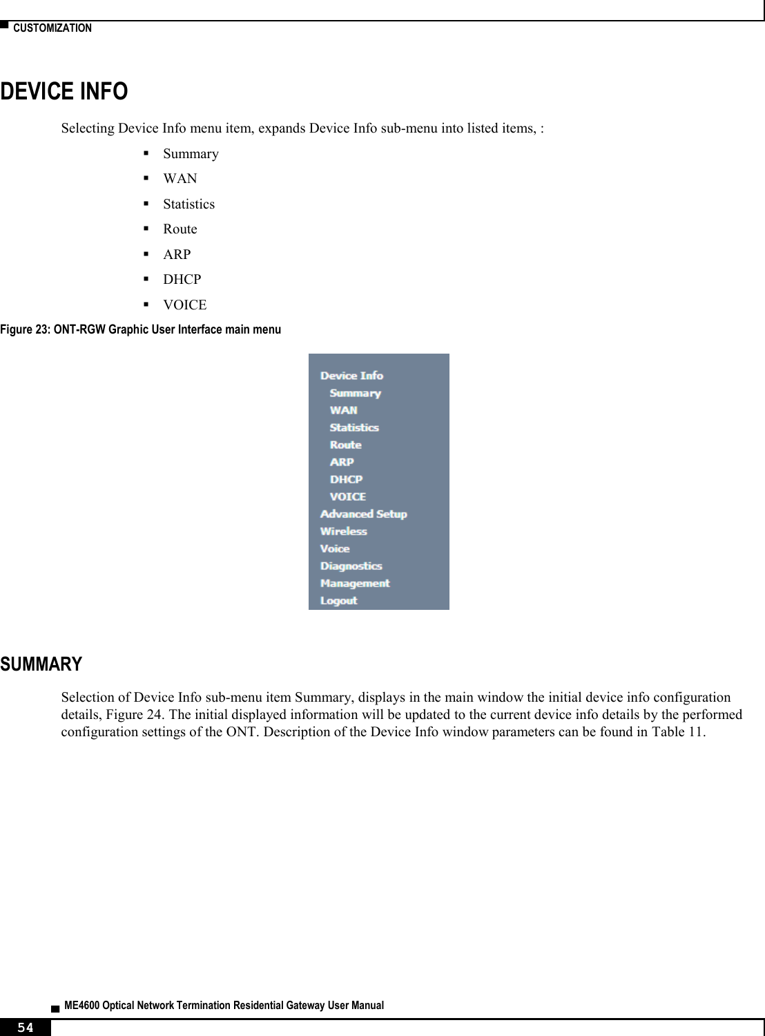
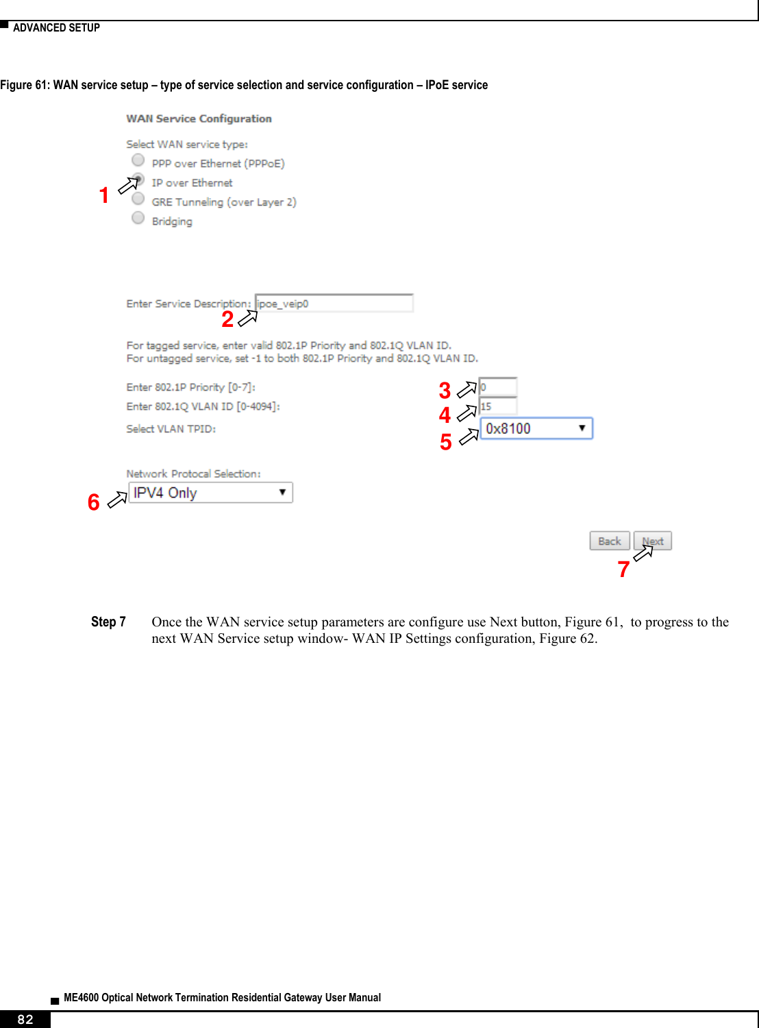
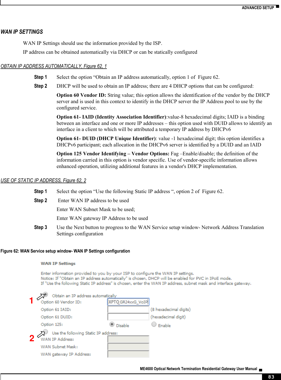
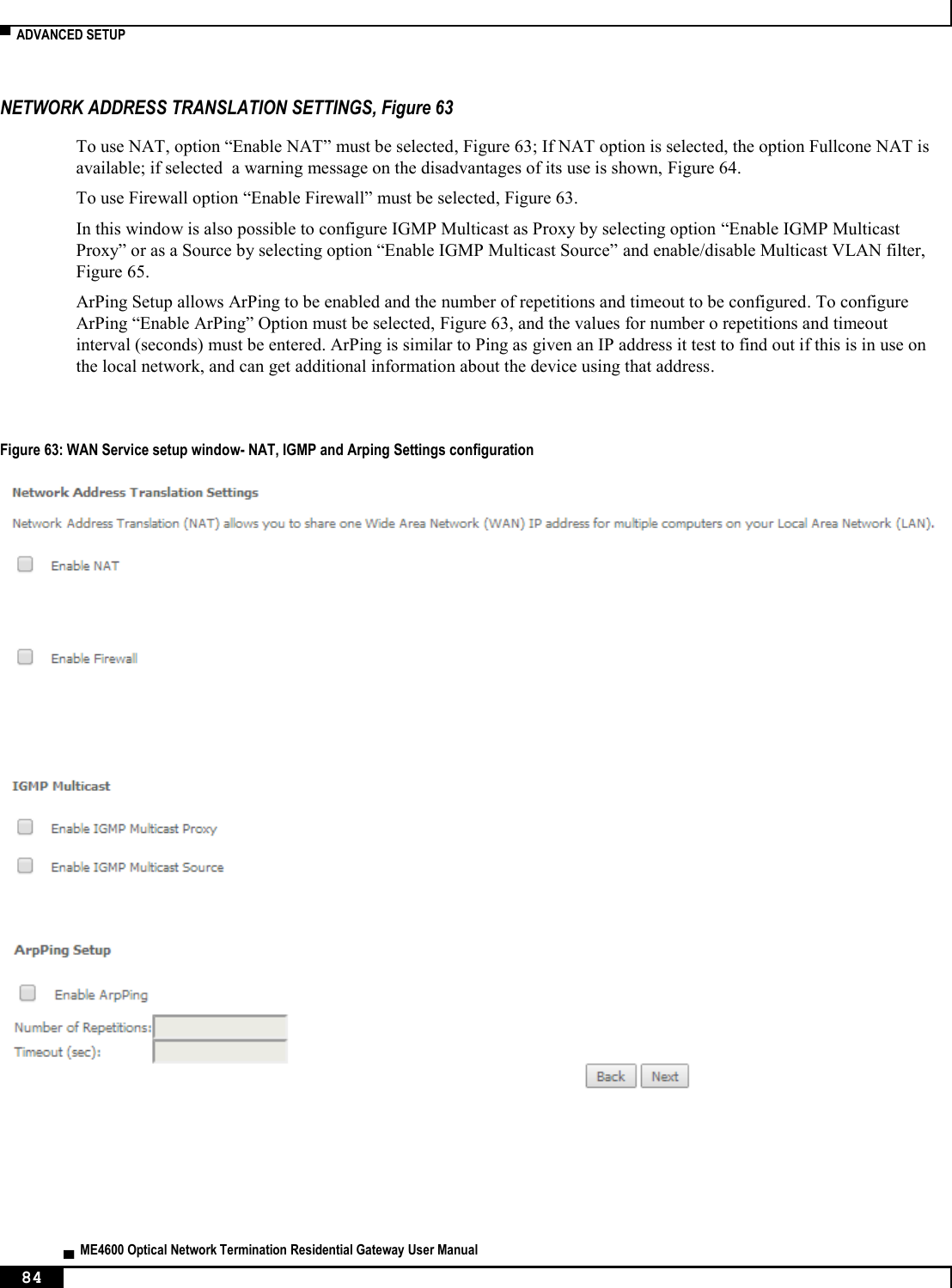
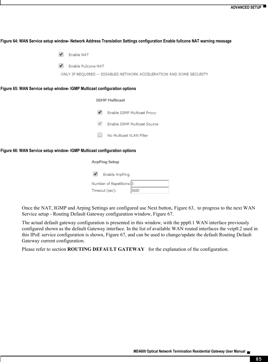
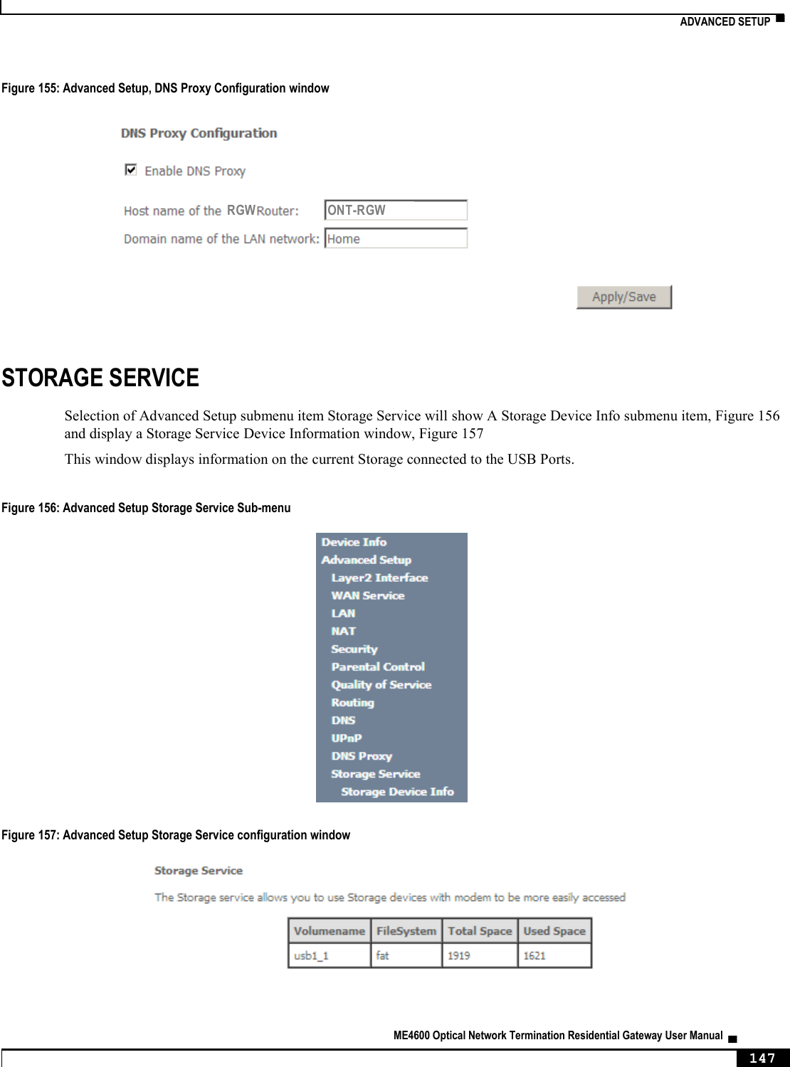
![▀ ONT-RGW MAIN FUNCTIONALITIES ▄ ME4600 Optical Network Termination Residential Gateway User Manual 28 Figure 11: Downstream QoS Diagram DYNAMIC BANDWIDTH ALLOCATION (DBA) The DBA (Dynamic Bandwidth Allocation) is available in order to optimize the upstream bandwidth. This mechanism consists in defining an adequate T-CONT to the service traffic in question. There are five types of T-CONT, defined by the Fixed, Assured and Maximum Parameters: Type 1: Only fixed Bandwidth; Type 2: Only Assured Bandwidth; Type 3: Assured + Maximum Bandwidth; Type 4: Only Maximum Bandwidth (Best Effort); Type 5: Fixed + Assured + Maximum Bandwidth. Table 1: T-CONT types definition T-CONT Type 1 Type 2 Type 3 Type 4 Type 5 Units Fixed BW- RF RF1 0 0 0 RF5 [b/s] Assured BW- RA 0 RA2 RA3 0 RA5 [b/s] Max Bw - RM RM1 = RF1 RM2 = RA2 RM3 > RA3 RM4 RM5 > RF5 + RA5 [b/s] Bandwidth Eligibility 0 0 Non-Assured BW - RNA Best-Effort - RBE RNA / RBE In each GPON interface there is 1024 Alloc-ID (T-CONT identifiers) available, provided to manage ONT services. They are distributed in the following way:](https://usermanual.wiki/Altice-Labs/ME4624-ONTRGW/User-Guide-2568279-Page-30.png)
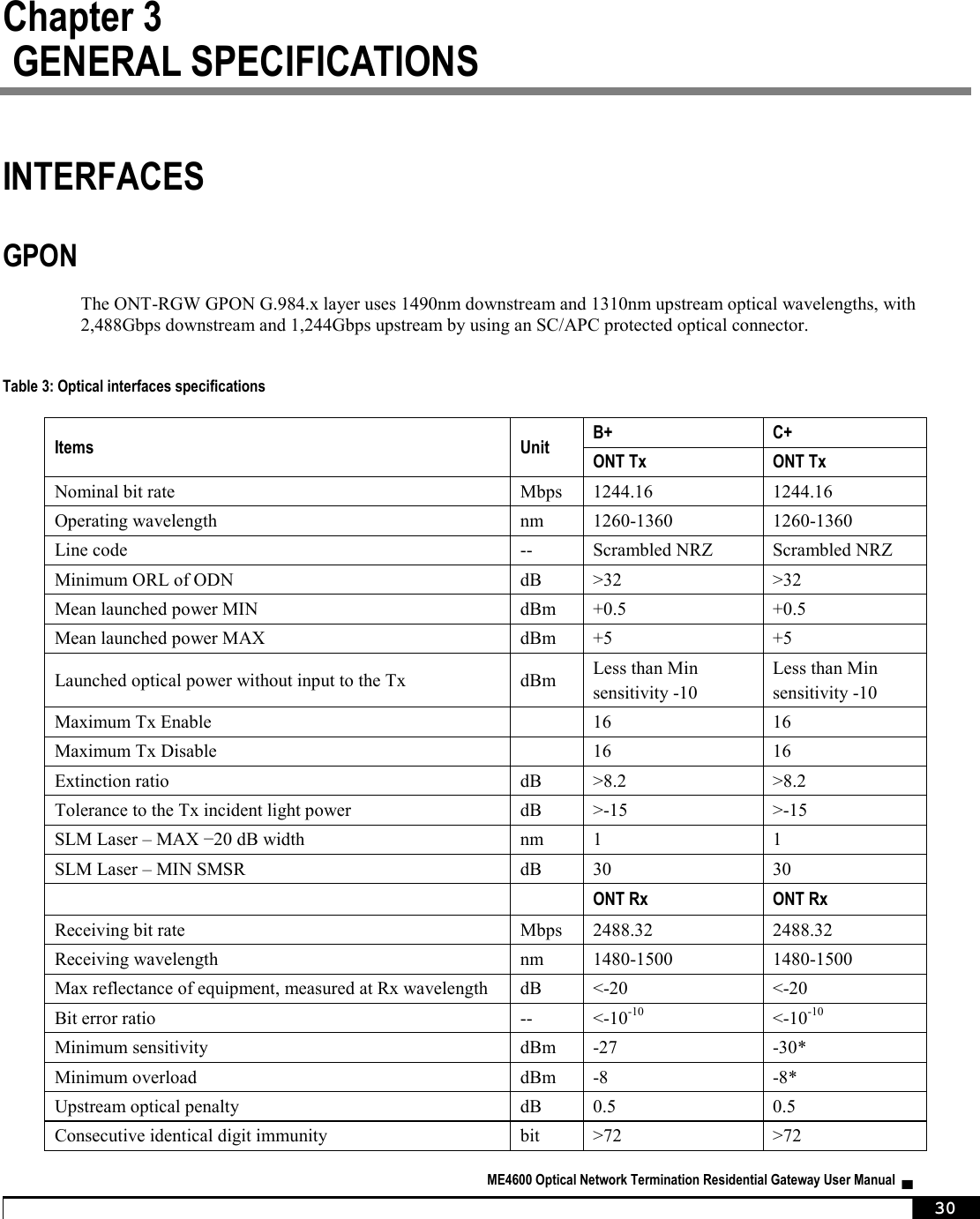
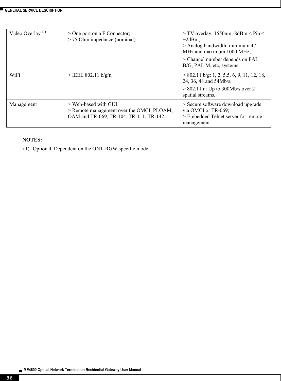
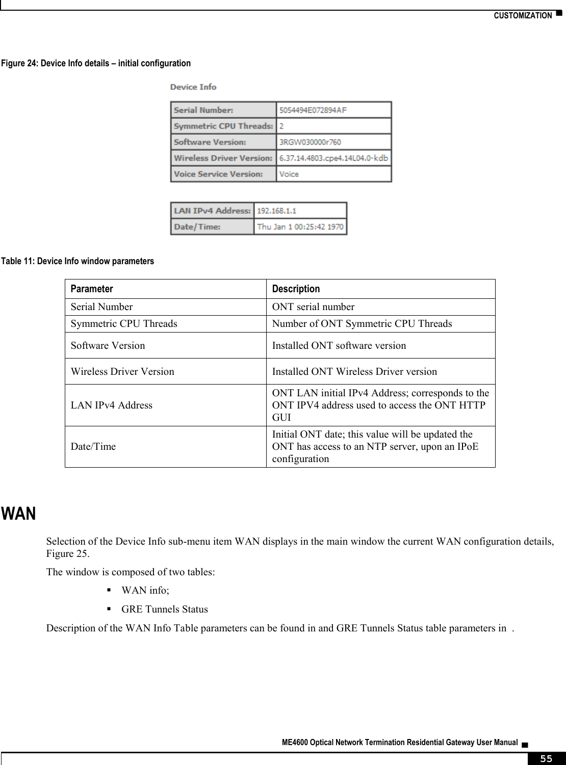
![INTERFACES ▀ ME4600 Optical Network Termination Residential Gateway User Manual ▄ 31 Tolerance to reflected optical power dB <10 <10 ONT Rx Video Receiving wavelength nm 1550-1560 * ONT RX= -8~-30 dBm (The ONT sensitivity assumes the use of the optional RS (255,239) FEC capability of the G-PON TC layer with the current class B+ ONU detector technology; The ONU overload is set at –8 dBm to be common with the class B+ value, even though in this application –10 dBm is sufficient). Optical solution: B+ and C+. Connector type: SC/APC. IEC 60825-1: "Class 1 Laser Product''. The B+ and C+ triplexer is embedded on the ONT equipment version. ONU Single Fiber - G.984.2 (03/2003) + G.984.2 Amd 1 (02/2006) and 2 (03/2008), G.983.3 (03/2001). ETHERNET Ethernet is the wired LAN technology and is revised in the IEEE 802.3 standard. At the OSI reference system, Ethernet is at the Data Link layer. In the ONT-RGW equipment the LAN type of physical interfaces is 10/100/1000BASE-T AUTO-MIX Ethernet type over RJ45 connectors. RF OVERLAY Broadcast video signal travels over fiber from the CO in the 1550nm wavelength and is demuxed and converted in the ONT-RGW to a F connector (75 Ohm) RF Overlay interface to deliver a RF TV signal going from 47MHz up to 1GHz of bandwidth. FXS Table 4: Interface specifications Items State Description Pulse Dialing Pulse Frequency: 10 Hz (8 Hz to 12 Hz) Pulse Relation: 66,6% (33% to 75%) Interdigital Pause and Pre-Dialing: 400 ms (min) - DTMF - According to ETSI CTR 21 [1] Clip - According to ETSI 300 659-1 Clip on Call Waiting - According to ETSI 300 659-2 DC voltage (V) -48V (-46 to -54) - Loop Current Characteristics (A) 20mA (min) to 60mA (max) - Ifeed Max. (A) 45mA -](https://usermanual.wiki/Altice-Labs/ME4624-ONTRGW/User-Guide-2568279-Page-33.png)
![▀ INTERFACES ▄ ME4600 Optical Network Termination Residential Gateway User Manual 32 Items State Description Impedance and Transmission Requirements (Ω) Q.552 [4] (11/96) of ITU-T 220Ω+820Ω//115nF. A telephone that comply with transmission requirements defined in CTR 38, should comply with SLR, RLR and STMR (4.2.2.1, 4.2.2.2 and 4.2.3) standard requisites, when connected to a FXS interface. ILA (A) 20 – 45 mA 5 bit parameter which sets the current limit for DC feed (DC feed and battery switch are programmed and calibrated to ILA=26mA, VOC=48V, VAS=3V, bshv=5V). Ringer voltage (V) DC offset: 48V AC voltage: 75Vrms +/- 0.5% Frequency: 25Hz +/- 3% - Ringing signal normal ringing 1 sec ring / 5 sec pause (interval = 6 sec). Hook flash on-hook - register recall/hook flash 100 msec Minimum time of recognition of “on-hook” when hook-flash feature does not exist on-hook - register recall/hook flash 1000 msec Minimum time “on-hook” recognition when hook-flash feature does exist off-hook 40 msec minimum time “off-hook” recognition interval 160msec - 400msec Time calibrated break pulse duration for register recall recognition NOTE: FXS interface specific parameter values vary according to country adopted standards. ONT-RGW FXS interface specifications table values are configurable at the web management interface at the menu Voice, item SIP basic settings, by selecting the local(Country) where the ONT-RGW will be used. Please refer to section SIP BASIC SETTING, for details on this configuration. WIFI Table 5: WIFI specification Items Compliance Description IEEE 802.11 b/g/n - Bit Rates 802.11 b/g 1, 2, 5.5, 6, 9, 11, 12, 18, 24, 36, 48 and 54Mb/s 802.11 n Up to 300Mb/s over two spatial streams SSID - Up to 8 Operation Frequencies - 2.4GHz (ISM) or 5GHz (U-NII) Channels - 20MHz and 40MHz channels MIMO - 2x2 MCS - supported values: 0-15 and 32 Wireless Security WEP 40bit secure key and 24 bit as defined in 802.11-2007](https://usermanual.wiki/Altice-Labs/ME4624-ONTRGW/User-Guide-2568279-Page-34.png)
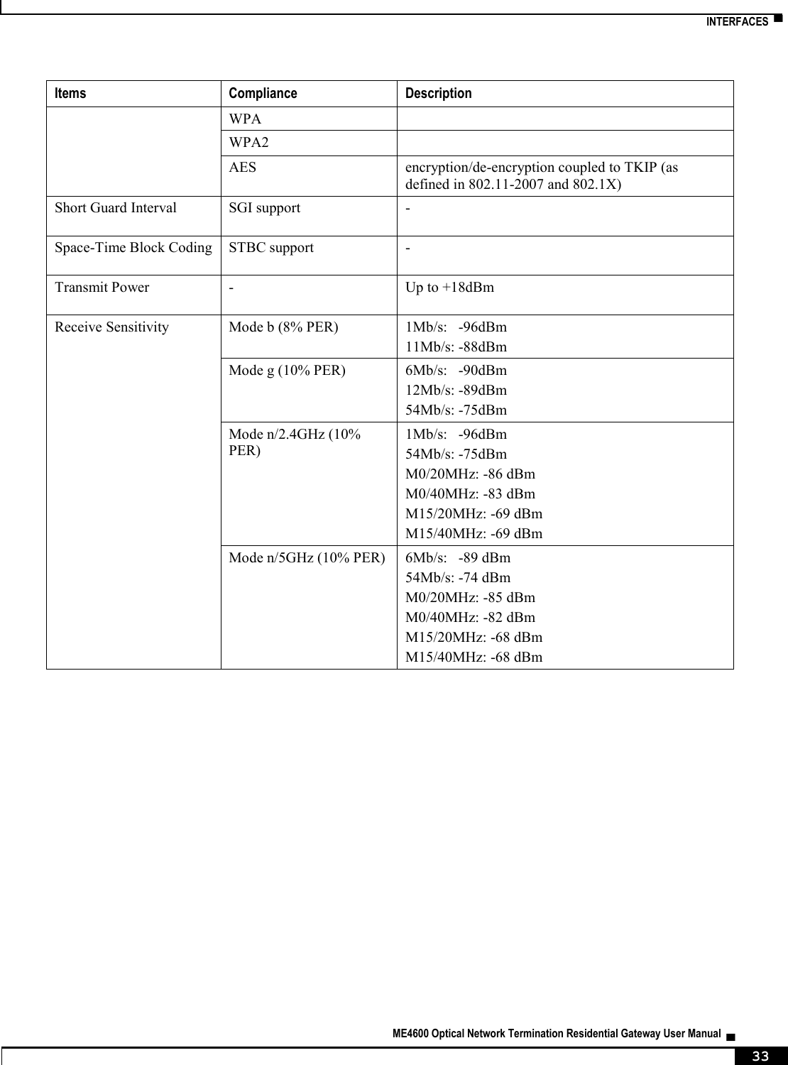
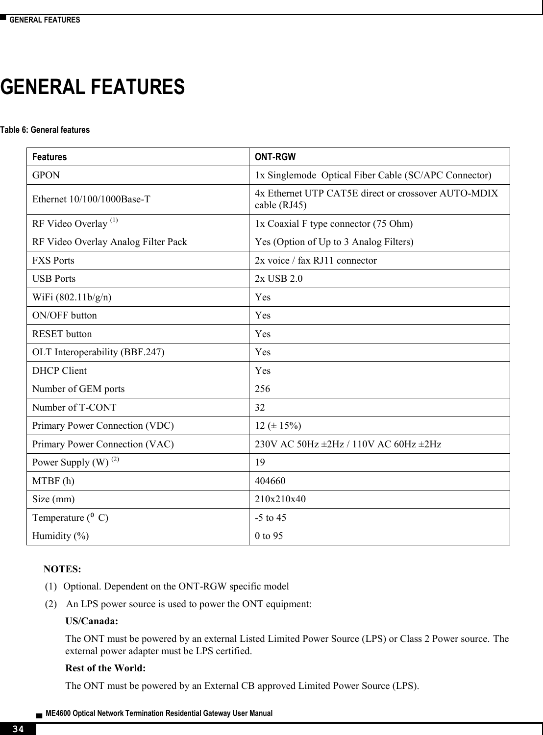


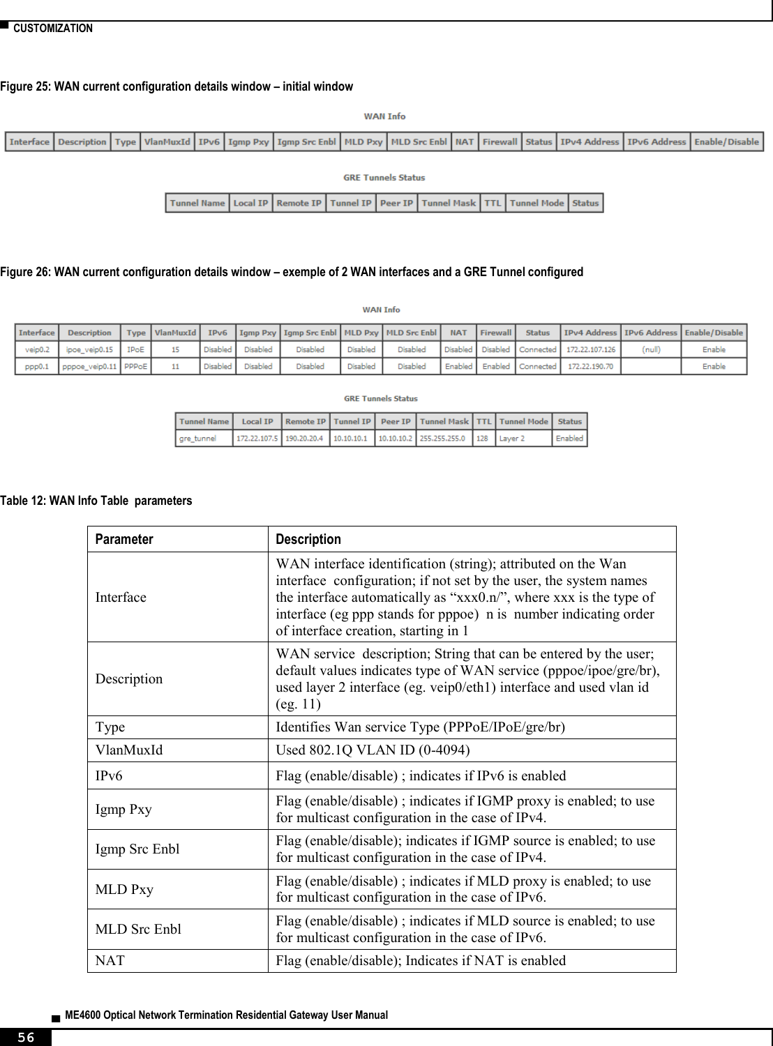
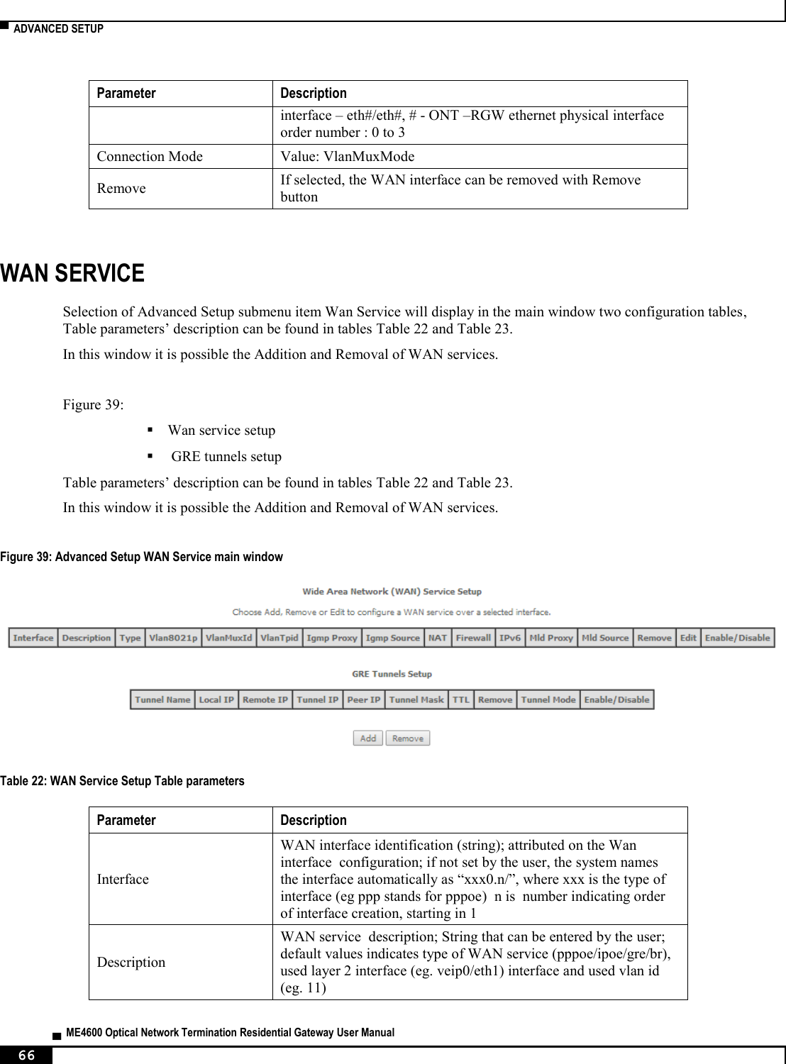


![▀ NODES AND COMMANDS ▄ ME4600 Optical Network Termination Residential Gateway User Manual 194 NODES AND COMMANDS “wan” node This node allows a user to see, to add and/or to delete wan services. The available wan services are: IPoE, PPPoE, Bridging and GRE. In order to configure one service, the user should enter the respective node (ex: /cli> cd ipoe) and then type the desired command. The user can see the configured wan interfaces by typing “show” on the interfaces node. Figure 217: wan node tree + wan[@show] + bridge[@create, @remove, @show] + gre[@create, @remove, @show] + interfaces[@show] + ipoe[@create, @remove, @show] + pppoe[@create, @remove, @show] PERMISSIONS Table 28: wan node and sub-node tree command permissions Command Admin Support User /wan/show Yes Yes Yes /wan/ipoe/create Yes Yes No /wan/ipoe/remove Yes Yes No /wan/ipoe/show Yes Yes Yes /wan/pppoe/create Yes Yes No /wan/ pppoe /remove Yes Yes No /wan/ pppoe /show Yes Yes Yes /wan/gre/create Yes Yes No /wan/ gre /remove Yes Yes No /wan/ gre /show Yes Yes Yes /wan/bridge/create Yes Yes No /wan/ bridge /remove Yes Yes No /wan/ bridge /show Yes Yes Yes /wan/interfaces/show Yes Yes No](https://usermanual.wiki/Altice-Labs/ME4624-ONTRGW/User-Guide-2568279-Page-196.png)
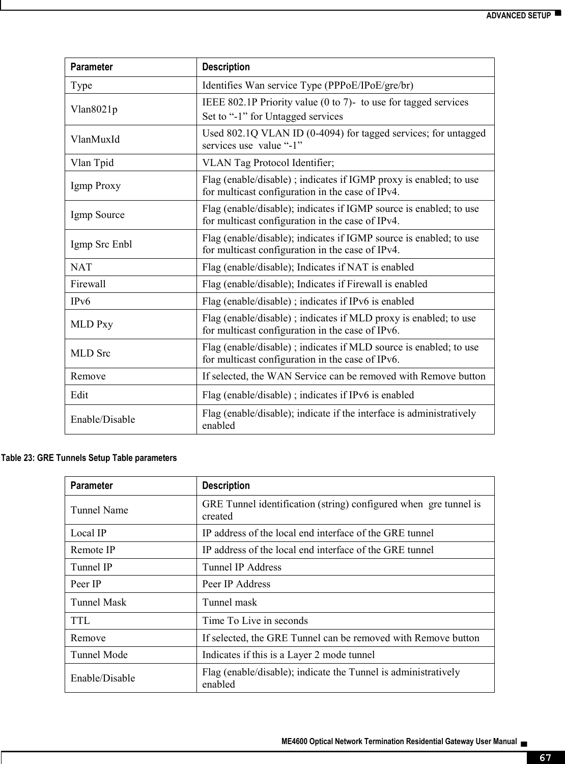
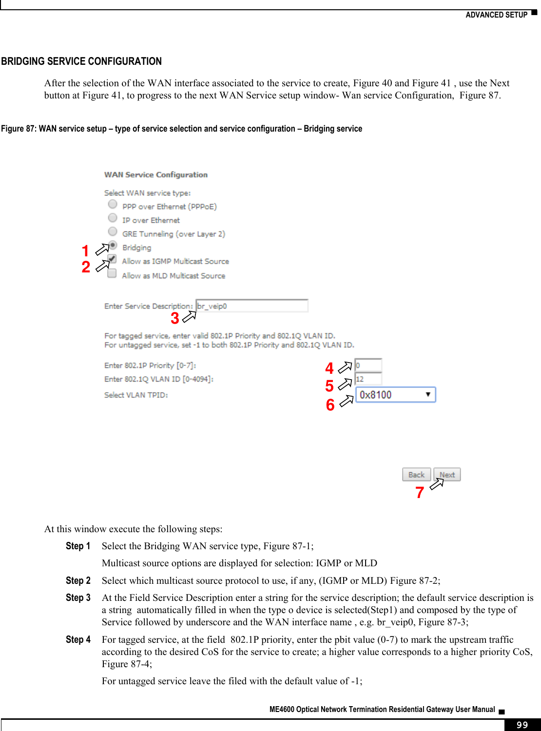
![NODES AND COMMANDS ▀ ME4600 Optical Network Termination Residential Gateway User Manual ▄ 195 “bridge” sub-node “create” command Table 29: "create" command information Name create Description Creates a new bridging service Full Path /wan/bridge/create Arguments <MANDATORY> --interface WAN L2 Interface [OPTIONAL] --igmp-mcast IGMP Multicast <enable|disable> (disable by default) --mld-mcast MLD Multicast <enable|disable> (disable by default) --pbit 802.1P Priority [0-7] (-1 by default) --service-name Service description --vlan 802.1Q VLAN ID [0-4094] (-1 by default) “remove” command Table 30: "remove" command information remove remove Description Removes an existing bridging service Full Path /wan/bridge/remove Arguments <MANDATORY> --if-to-rmv WAN Interface “gre” sub-node “create” command Table 31: "create" command information Name create Description Creates a new GRE service Full Path /wan/gre/create Arguments](https://usermanual.wiki/Altice-Labs/ME4624-ONTRGW/User-Guide-2568279-Page-197.png)
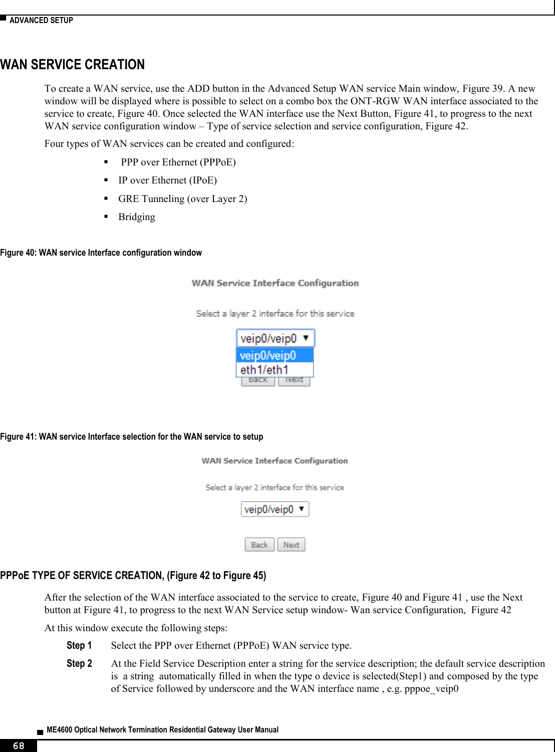
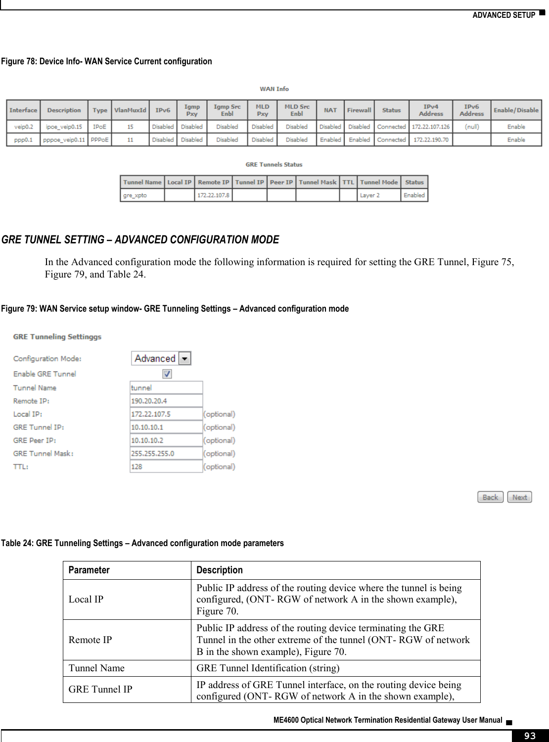
![▀ NODES AND COMMANDS ▄ ME4600 Optical Network Termination Residential Gateway User Manual 196 <MANDATORY> --interface Interface --remote-ip Remote IP --tunnel-name Tunnel Name [OPTIONAL] --local-ip Local IP --peer-ip Peer IP --ttl TTL [0, 255] --tunnel-ip Tunnel IP --tunnel-mask Tunnel mask “remove” command Table 32: "remove" command information remove remove Description Removes an existing GRE service Full Path /wan/gre/remove Arguments <MANDATORY> --tunnel-name Tunnel Name “interface” sub-node “ipoe” sub-node “create” command Table 33: "create" command information Name create Description Creates a new IPoE service Full Path /wan/gre/create Arguments <MANDATORY> --interface Interface [OPTIONAL] --arpping ArpPing <enable|disable> (disable by default) --dhcp-client DHCP Client <enable|disable> (enable by default) --dhcp-op125 DHCP Option 125 <enable|disable> (disable by default) --dhcp-op60-vid DHCP Option 60 Vendor ID --dhcp-op61-duid DHCP Option 61 DUID (hexadecimal digit) --dhcp-op61-iaid DHCP Option 61 IAID (8 hexadecimal digits)](https://usermanual.wiki/Altice-Labs/ME4624-ONTRGW/User-Guide-2568279-Page-198.png)
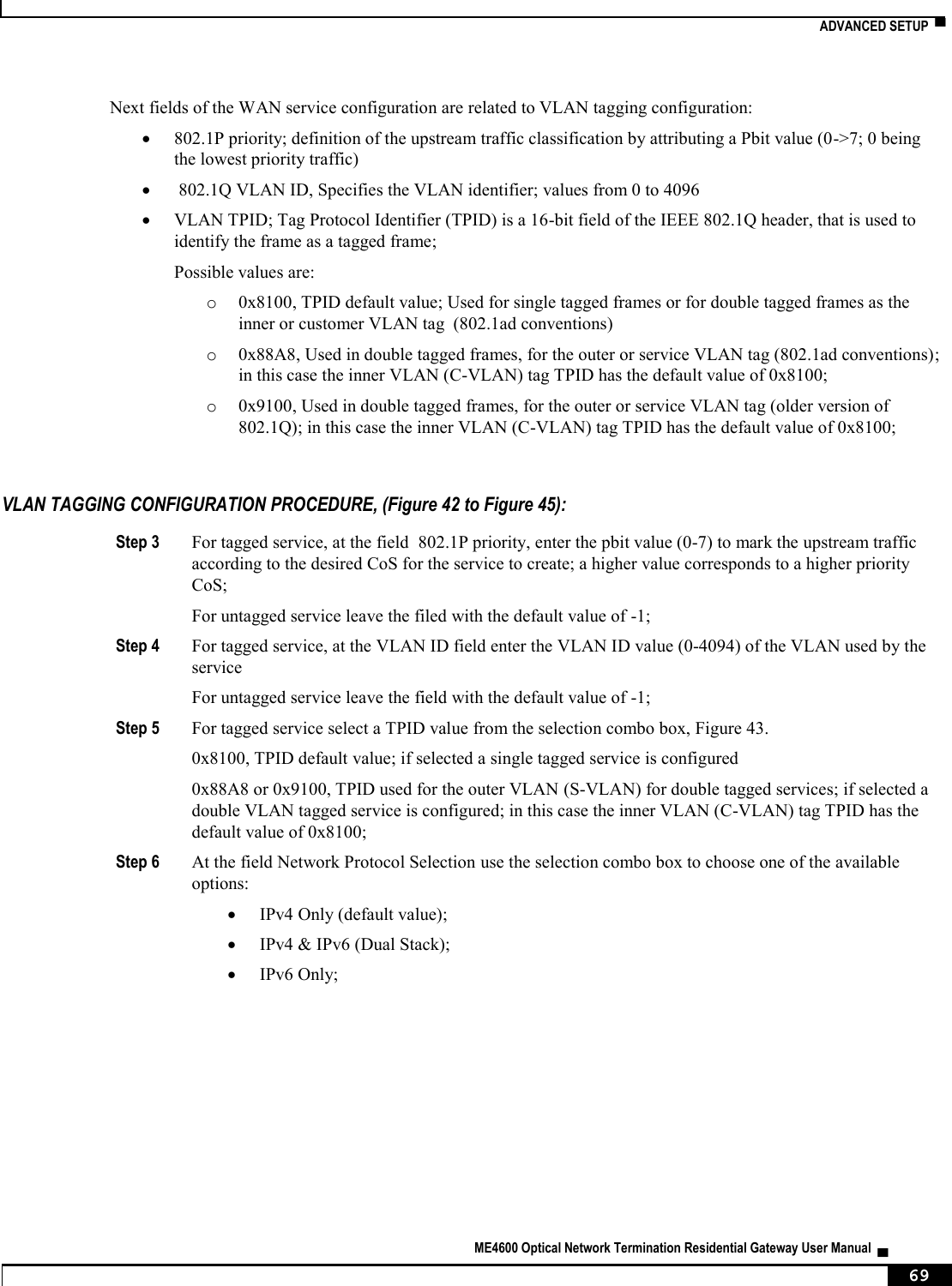
![NODES AND COMMANDS ▀ ME4600 Optical Network Termination Residential Gateway User Manual ▄ 197 --dhcp6c-iana Launch Dhcp6c for Address Assignment (IANA) <enable|disable> (disable by default) --dhcp6c-iapd Launch Dhcp6c for Prefix Delegation (IAPD) <enable|disable> (enable by default) --firewall Firewall <enable|disable> (disable by default) --fullcone Fullcone NAT <enable|disable> (disable by default) --igmp IGMP Multicat Proxy <enable|disable> (disable by default) --igmp-mcast-src IGMP Multicast Source <enable|disable> (disable by default) --ip-version Network Protocol <ipv4|ipv6|dual> (IPv4 by default) --mld MLD Multicat Proxy <enable|disable> (disable by default) --mld-mcast-src MLD Multicast Source <enable|disable> (disable by default) --nat NAT <enable|disable> (disable by default) --nat-mask Subnet mask --nat-masquerade NAT Masquerade <enable|disable> (disable by default) --nat-max-add End IP Address --nat-min-add Start IP Address --no-mcast-vlan-filter Multicast VLAN Filter <enable|disable> (disable by default) --nr-rep ArpPing number of repetitions [1, 255] (3 by default) --pbit 802.1P Priority [0-7] (No PBIT by default) --service-name Service description --timeout ArpPing timeout (sec) [30, 3600] (3600 by default) --tpid VLAN TPID <0x8100|0x88A8|0x9100> (No VLAN TPID by default) --vlan 802.1Q VLAN ID [0-4094] (No VLAN by default) --wan-gw WAN gateway IP Address --wan-ip-add WAN IP Address --wan-ipv6-add Static IPv6 Address <WAN IPv6 Address/Prefix Length>. If the address prefix length is not specified, it will be default to /64. --wan-ipv6-next-hop WAN Next-Hop IPv6 Address --wan-mask WAN subnet mask](https://usermanual.wiki/Altice-Labs/ME4624-ONTRGW/User-Guide-2568279-Page-199.png)
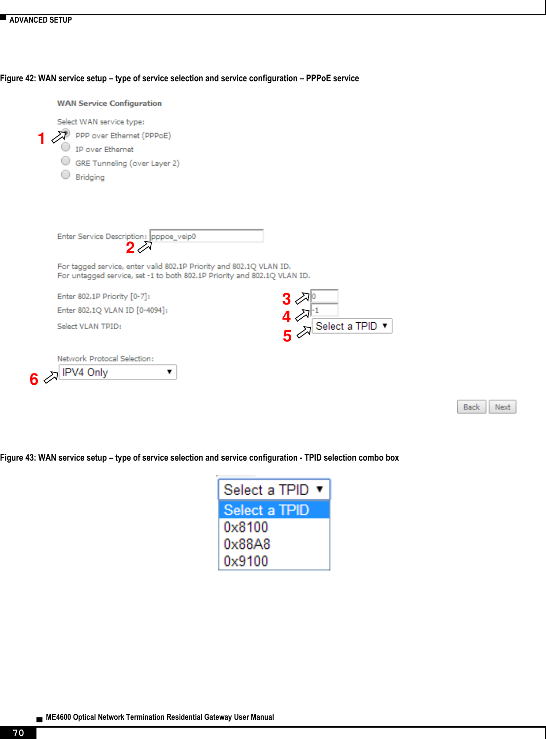
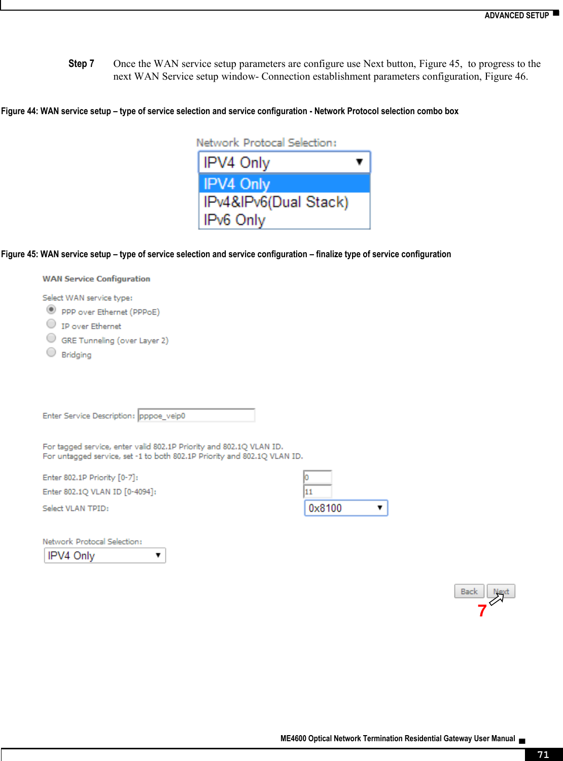
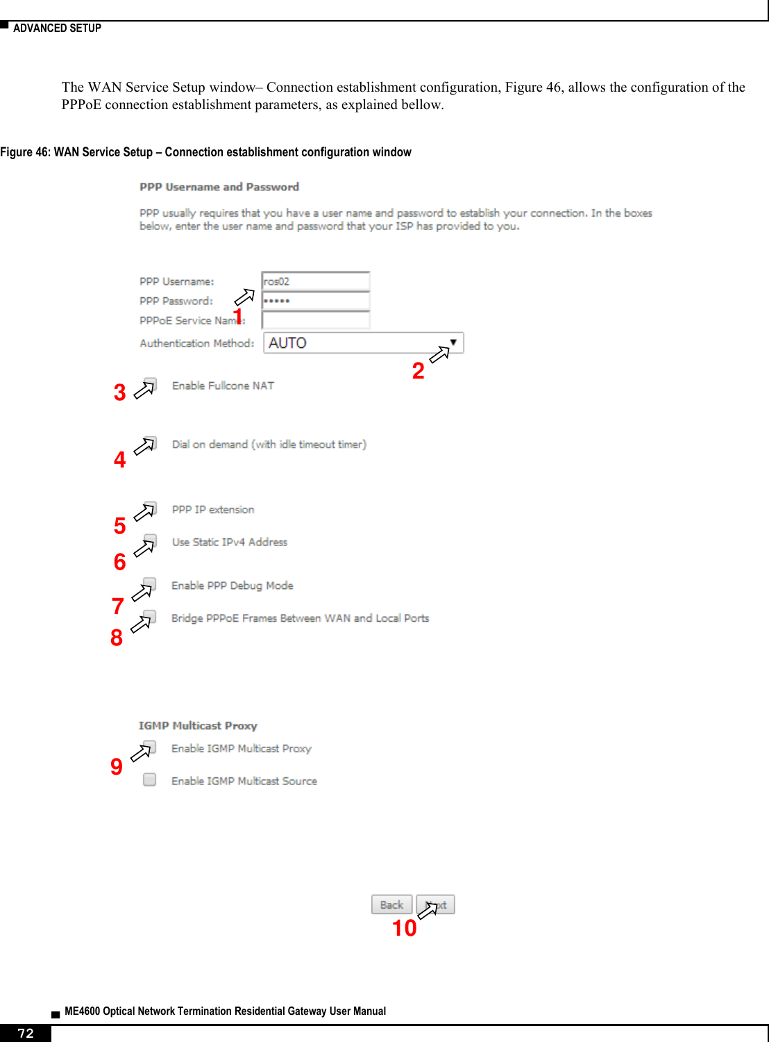
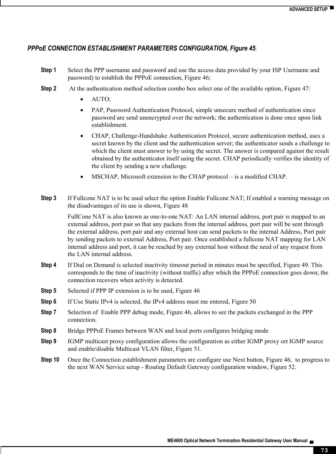
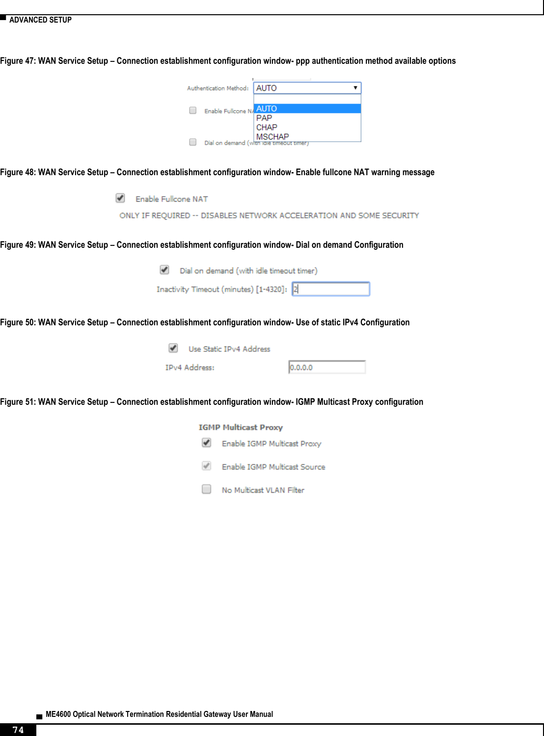
![▀ NODES AND COMMANDS ▄ ME4600 Optical Network Termination Residential Gateway User Manual 198 “remove” command Table 34: "remove" command information remove remove Description Removes an existing IPoE service Full Path /wan/ipoe/remove Arguments <MANDATORY> --if-to-rmv WAN Interface “pppoe” sub-node “create” command Table 35: "create" command information Name create Description Creates a new PPPoE service Full Path /wan/pppoe/create Arguments <MANDATORY> --interface Interface [OPTIONAL] --auth-error-retry Authentication error retry <enable|disable> (disable by default) --auth-method Authentication method <AUTO|PAP|CHAP|MSCHAP> (AUTO by default) --debug PPP Debug Mode <enable|disable> (disable by default) --dhcp6c-iana Launch Dhcp6c for Address Assignment (IANA) <enable|disable> (disable by default) --dhcp6c-iapd Launch Dhcp6c for Prefix Delegation (IAPD) <enable|disable> (enable by default) --firewall Firewall <enable|disable> (disable by default) --fullcone Fullcone NAT <enable|disable> (disable by default) --igmp IGMP Multicat Proxy <enable|disable> (disable by default) --igmp-mcast-src IGMP Multicast Source <enable|disable> (disable by default) --ipv4-add Static IPv4 Address --ipv6-add Static IPv6 Address --ipv6-unnumbered-model IPv6 Unnumbered model <enable|disable> (enable by default) --mld MLD Multicat Proxy <enable|disable>](https://usermanual.wiki/Altice-Labs/ME4624-ONTRGW/User-Guide-2568279-Page-200.png)
![NODES AND COMMANDS ▀ ME4600 Optical Network Termination Residential Gateway User Manual ▄ 199 (disable by default) --mld-mcast-src MLD Multicast Source <enable|disable> (disable by default) --ip-version Network Protocol <ipv4|ipv6|dual> (IPv4 by default) --no-mcast-vlan-filter Multicast VLAN Filter <enable|disable> (disable by default) --on-demand Dial on demand (with idle timeout timer) <enable|disable> --password PPP Password --pbit 802.1P Priority [0-7] (-1 by default) --server-name PPPoE server name --service-name Service description --timeout Inactivity Timeout (minutes) [1-4320] --to-bridge Bridge PPPoE Frames Between WAN and Local Ports <enable|disable> (disable by default) --tpid VLAN TPID <0x8100|0x88A8|0x9100> (-1 by default) --username PPP Username --vlan 802.1Q VLAN ID [0-4094] (-1 by default) “remove” command Table 36: "remove" command information remove remove Description Removes an existing PPPoE service Full Path /wan/pppoe/remove Arguments <MANDATORY> --if-to-rmv WAN Interface “lan” node This node allows a user to configure the LAN settings. It allows the configuration of generic LAN settings, as well as setup the LAN VLAN and the configuration of the available Ethernet LAN ports. Figure 218: lan node tree + lan[@config, @show] + interfaces[@config, @show] + static-lease[@create, @remove, @show] + vlan[@create, @remove, @show]](https://usermanual.wiki/Altice-Labs/ME4624-ONTRGW/User-Guide-2568279-Page-201.png)
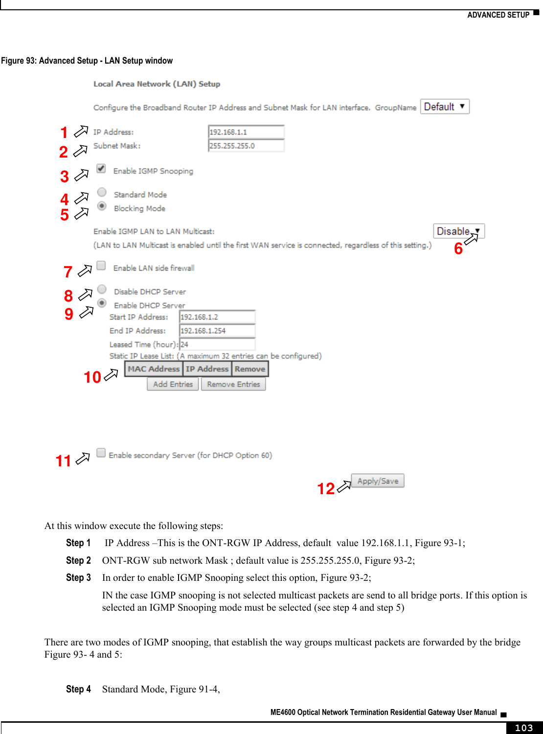
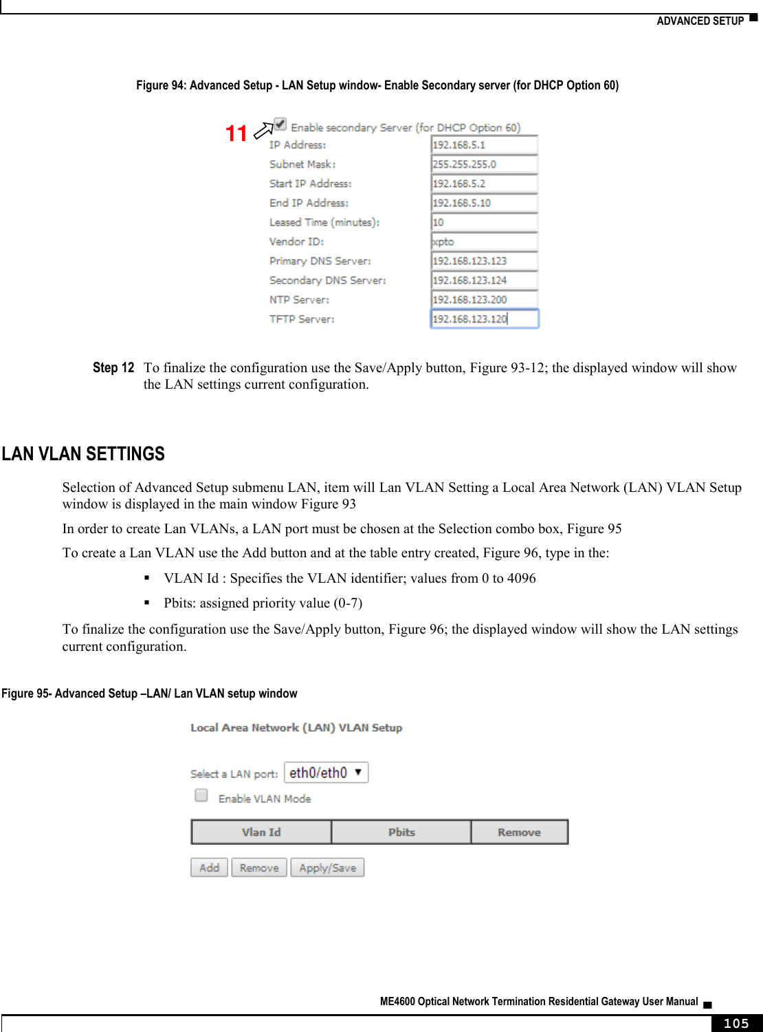
![▀ NODES AND COMMANDS ▄ ME4600 Optical Network Termination Residential Gateway User Manual 200 PERMISSIONS Table 37: lan node and sub-node tree command permissions Command Admin Support User /lan/show Yes Yes Yes /lan/config Yes Yes Yes /lan/interfaces/show Yes Yes No /lan/interfaces/config Yes Yes No /lan/static-lease/create Yes Yes No /lan/static-lease /remove Yes Yes No /lan/static-lease /show Yes Yes No /lan/vlan/create Yes Yes No /lan/vlan /remove Yes Yes No /lan/vlan/show Yes Yes No “config” command Table 38: "config" command information Name config Description Configures the LAN Full Path /lan/config Arguments [OPTIONAL] --default-gw Default gateway (0.0.0.0 by default) --dhcp-end DHCP End IP address (192.168.1.254 by default) --dhcp-server DHCP Server <enable|disable> (enable by default) --dhcp-start DHCP Start IP address (192.168.1.2 by default) --dns-primary Primary DNS (0.0.0.0 by default) --dns-sec Secondary DNS --firewall LAN side firewall <enable|disable> (disable by default) --igmp-mode IGMP mode <standard|blocking> (blocking by default) --igmp-snoop IGMP Snooping <enable|disable> (enable by default) --ip-add IP address (192.168.1.1 by default) --lan-to-lanMcast IGMP LAN to LAN Multicast <enable|disable> (disable by default) --lan2 Secondary Server (for DHCP Option 60) <enable|disable> (disable by default) --lan2-dns-prim Sec. server primary DNS --lan2-end Sec. server end IP address](https://usermanual.wiki/Altice-Labs/ME4624-ONTRGW/User-Guide-2568279-Page-202.png)
![NODES AND COMMANDS ▀ ME4600 Optical Network Termination Residential Gateway User Manual ▄ 201 --lan2-ip Sec. server IP address --lan2-leased-time Sec. server leased time (minutes) --lan2-mask Sec. server subnet mask --lan2-ntp NTP server --lan2-sec-dns Sec. server secondary DNS --lan2-start Sec. server start IP address --lan2-tftp TFTP server --lan2-vendor-id Sec. server vendor ID --leased-time Leased Time (hours) (24 by default) --mask Subnet mask (255.255.255.0 by default) “interfaces” sub-node “config” command Table 39: "config" command information Name config Description Configures the state of the Ethernet LAN ports Full Path /lan/interfaces/config Arguments <MANDATORY> --interface LAN Interface [OPTIONAL] --admin-status Admin status <UP|DOWN> (UP by default) --speed Speed (Mb/s) <AUTO|10|100> (AUTO by default) “static-lease” sub-node “create” command Table 40: "create" command information Name create Description Creates a new entry on the static IP lease list Full Path /wan/static-lease/create Arguments <MANDATORY> --ip IP address --mac MAC address](https://usermanual.wiki/Altice-Labs/ME4624-ONTRGW/User-Guide-2568279-Page-203.png)
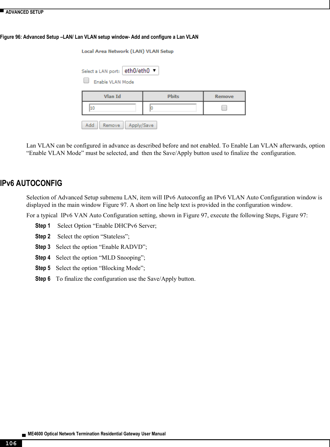
![▀ NODES AND COMMANDS ▄ ME4600 Optical Network Termination Residential Gateway User Manual 202 “remove” command Table 41: "remove" command information remove remove Description Removes an existing entry on the static IP lease list Full Path /lan/static-lease/remove Arguments <MANDATORY> --mac-to-rmv MAC address to remove “vlan” sub-node “create” command Table 42: "create" command information Name create Description Creates a new LAN VLAN entry Full Path /lan/vlan/create Arguments <MANDATORY> --interface LAN interface [OPTIONAL] --taglist vid1/pbit1|...|vidN/pbitN --vlan-mode VLAN Mode ON/OFF “remove” command Table 43: "remove" command information remove remove Description Removes an existing entry on the LAN VLAN list Full Path /lan/vlan/remove Arguments <MANDATORY> --interface LAN interface [OPTIONAL] --id Table Entry ID](https://usermanual.wiki/Altice-Labs/ME4624-ONTRGW/User-Guide-2568279-Page-204.png)
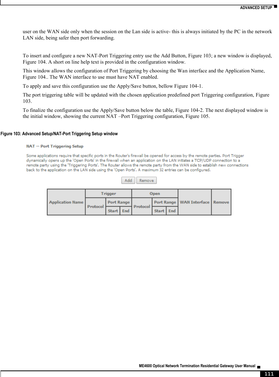
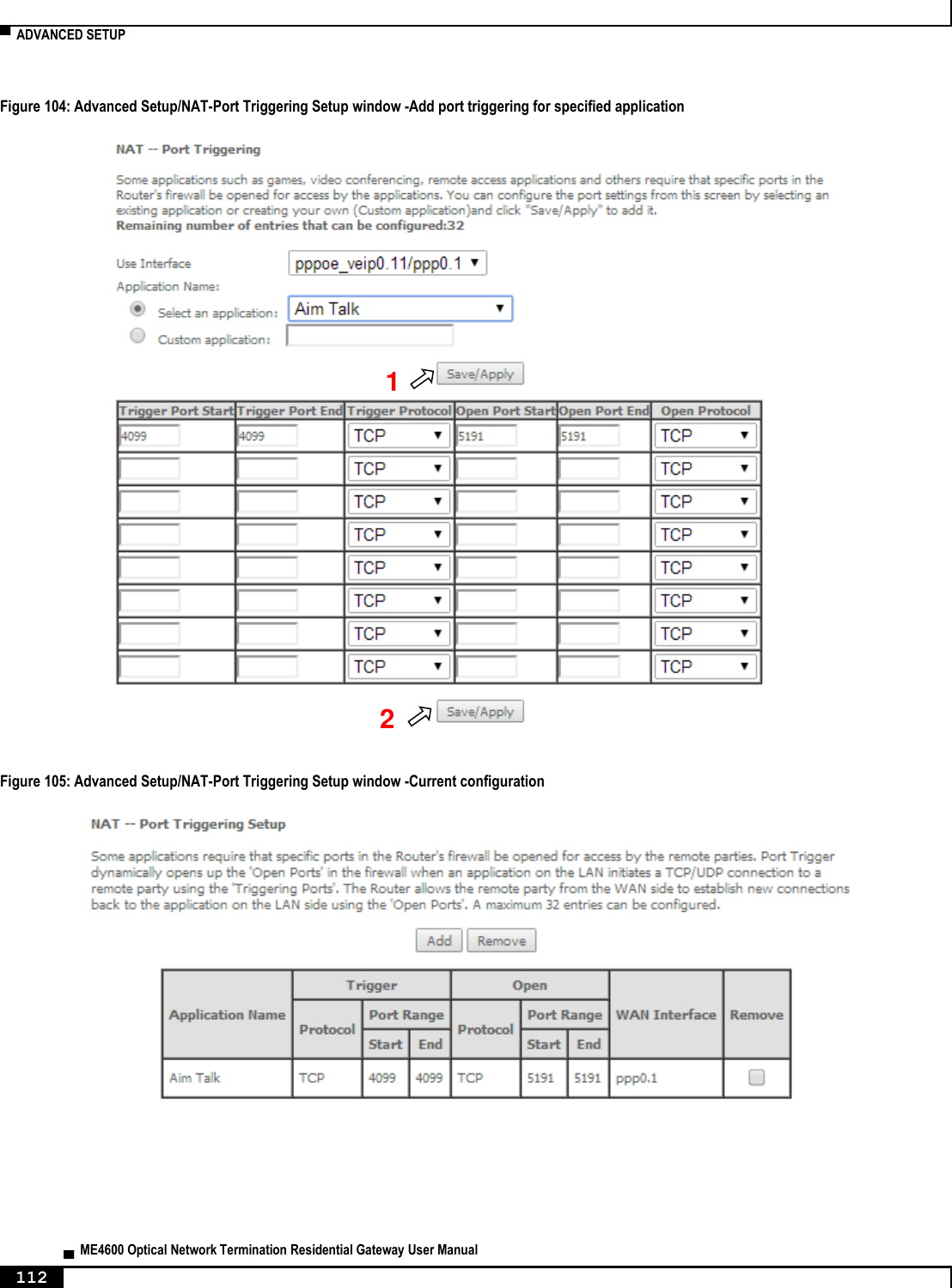
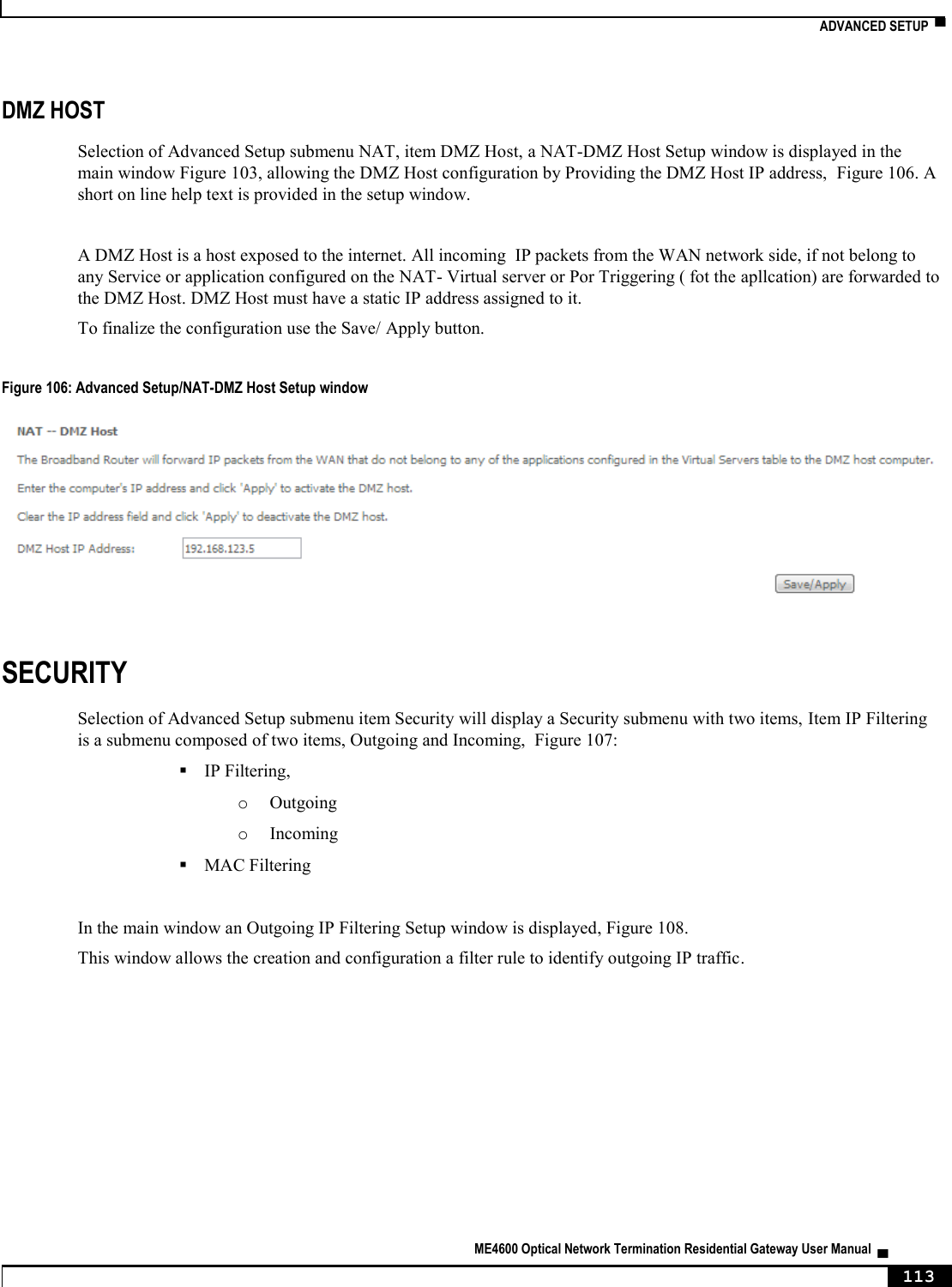
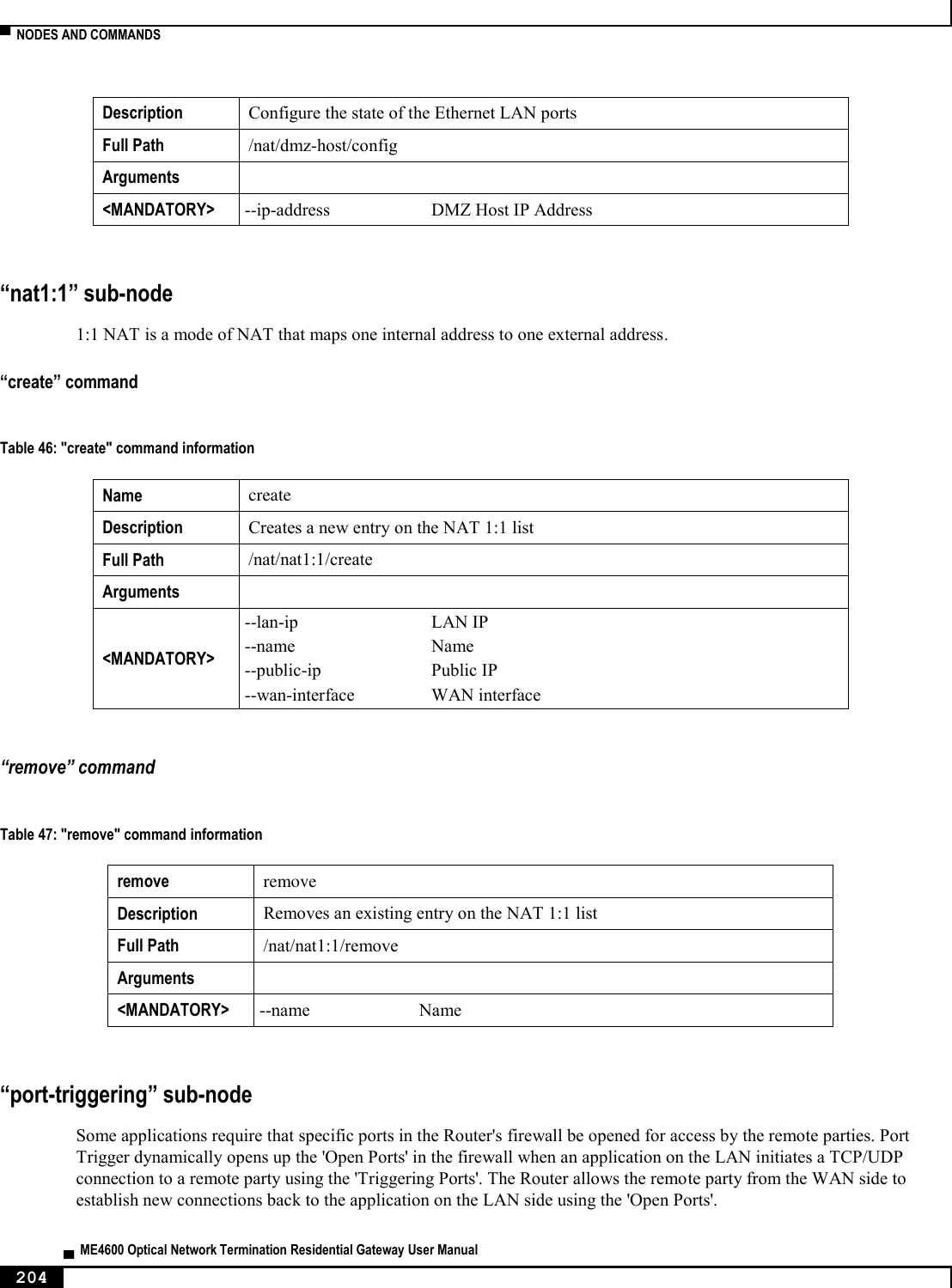
![NODES AND COMMANDS ▀ ME4600 Optical Network Termination Residential Gateway User Manual ▄ 203 “nat” node This node allows a user to configure the NAT (Network Address Translation) settings.. Figure 219: nat node tree + nat[] + dmz-host[@config, @show] + nat1:1[@create, @remove, @show] + port-triggering[@create, @remove, @show] + virtual-servers[@create, @remove, @show] PERMISSIONS Table 44: nat node and sub-node tree command permissions Command Admin Support User /nat/dmz-host/show Yes No No /nat/dmz-host/config Yes No No /nat/nat1:1/create Yes No No /nat/nat1:1/remove Yes No No /nat/nat1:1/show Yes No No /nat/port-triggering /create Yes No No /nat/port-triggering /remove Yes No No /nat/port-triggering /show Yes No No /nat/virtual-servers/create Yes Yes Yes /lan/virtual-servers/remove Yes Yes Yes /lan/virtual-servers/show Yes Yes Yes “dmz-host” sub-node The ONT-RGW will forward IP packets from the WAN that do not belong to any of the applications configured in the Virtual Servers table to the DMZ host computer. The user should pass the DMZ Host IP address as a parameter. “config” command Table 45: "config" command information Name config](https://usermanual.wiki/Altice-Labs/ME4624-ONTRGW/User-Guide-2568279-Page-205.png)
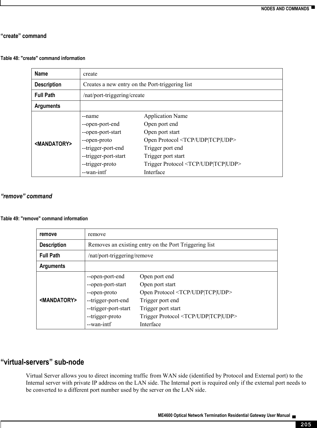
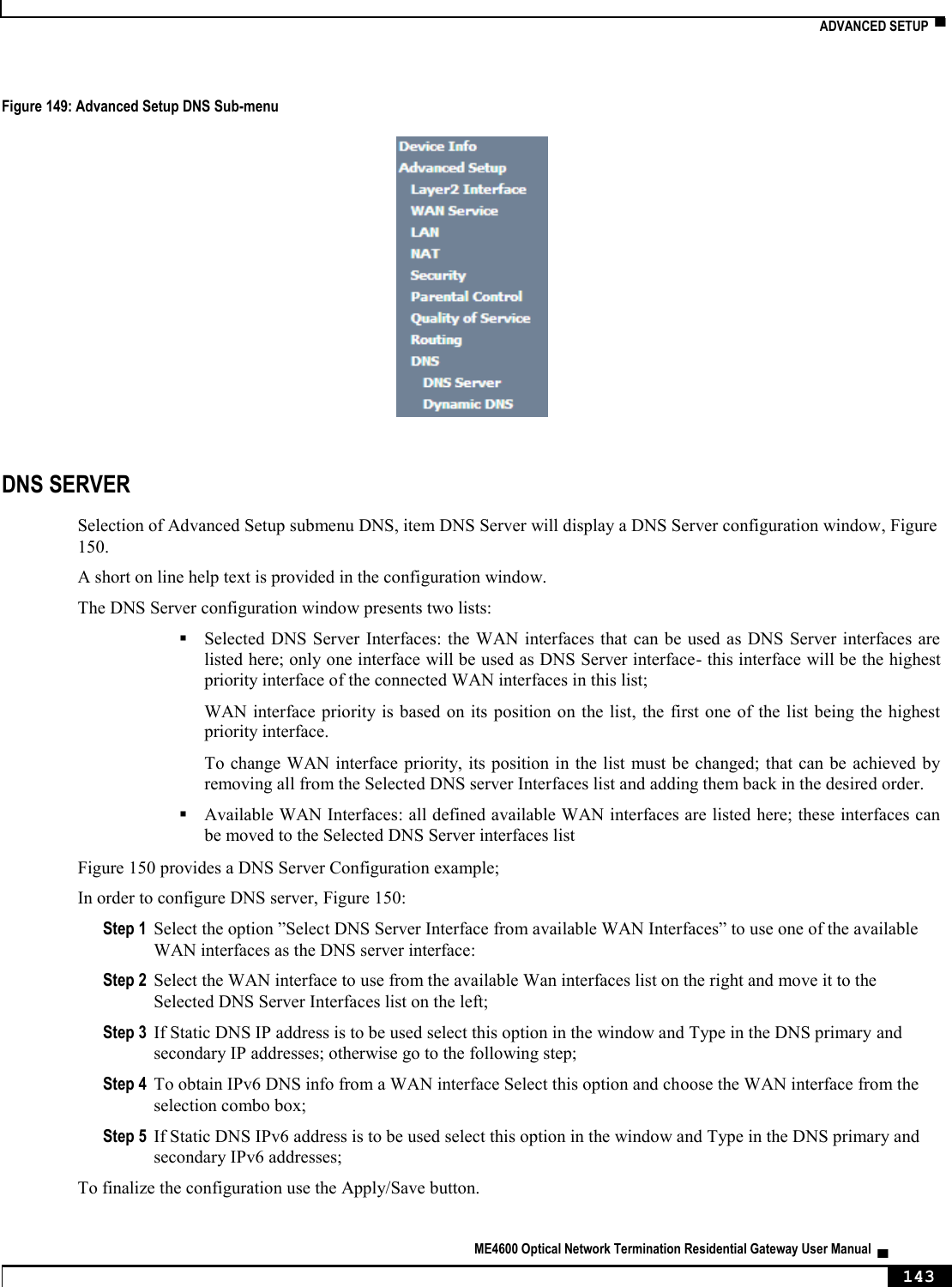
![▀ NODES AND COMMANDS ▄ ME4600 Optical Network Termination Residential Gateway User Manual 206 “create” command Table 50: "create" command information Name create Description Creates a new entry on the Virtual Servers list Full Path /nat/virtual-servers/create Arguments <MANDATORY> --ext-port-end External port end --ext-port-start External port start --int-port-start Internal port start --protocol Protocol <TCP/UDP|TCP|UDP> --server-ip Server IP address --server-name Service Name --wan-intf Interface [OPTIONAL] --int-port-end Internal port end (if not set it will have the same value as External Port End) “remove” command Table 51: "remove" command information remove remove Description Removes an existing entry on the Virtual Servers list Full Path /nat/virtual-servers/remove Arguments <MANDATORY> --ext-port-end External port end --ext-port-start External port start --int-port-start Internal port start --protocol Protocol <TCP/UDP|TCP|UDP> --server-ip Server IP address [OPTIONAL] --int-port-end Internal port end (if not set it will have the same value as External Port end) “dns” node This node allows a user to configure the DNS (Domain Name Server) server, as well as the the DNS proxy and the dynamic DNS service provider account information.](https://usermanual.wiki/Altice-Labs/ME4624-ONTRGW/User-Guide-2568279-Page-208.png)
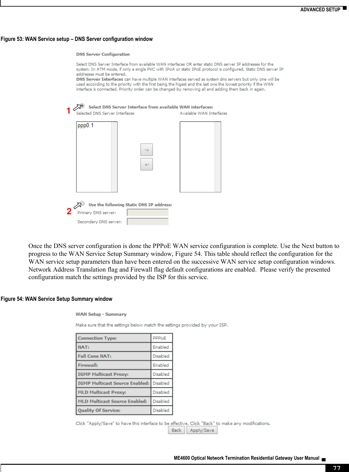
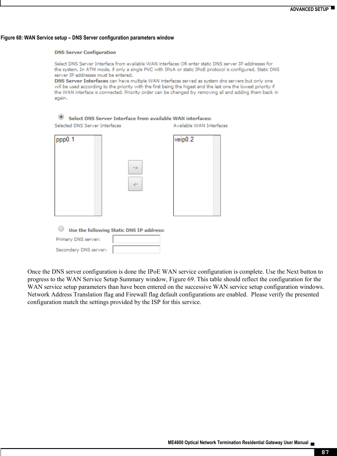
![NODES AND COMMANDS ▀ ME4600 Optical Network Termination Residential Gateway User Manual ▄ 207 Figure 220: dns node tree + dns[] + dynamic[@create, @remove, @show] + proxy[@config, @show] + server[@config, @show] PERMISSIONS Table 52: dns node and sub-node tree command permissions Command Admin Support User /dns/server/show Yes Yes No /dns/server/config Yes Yes No /dns/proxy/show Yes Yes No /dns/proxy/config Yes Yes No /dns/dynamic/show Yes Yes No /dns/dynamic /create Yes Yes No /dns/dynamic /remove Yes Yes No “server” sub-node This subnode is used to select a DNS Server Interface from available WAN interfaces or to enter a static DNS server IP addresses for the system. DNS Server Interfaces can have multiple WAN interfaces served as system DNS servers but only one will be used according to the priority with the first being the highest and the last one the lowest priority if the WAN interface is connected. “config” command Table 53: "config" command information Name config Description Configures a new entry on the DNS server interfaces list Full Path /dns/server/config Arguments <MANDATORY> [OPTIONAL]](https://usermanual.wiki/Altice-Labs/ME4624-ONTRGW/User-Guide-2568279-Page-209.png)
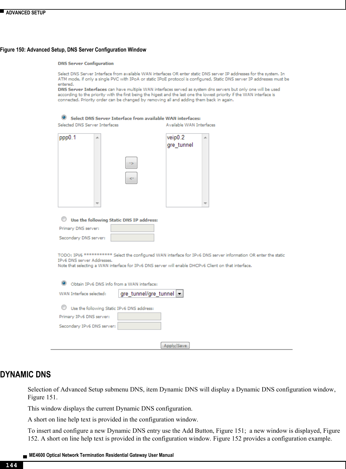
![▀ NODES AND COMMANDS ▄ ME4600 Optical Network Termination Residential Gateway User Manual 208 “proxy” sub-node This subnode can be used by the user to enable/disable and to configure a DNS proxy. “config” command Table 54: "config" command information Name config Description Configures the DNS proxy Full Path /dns/proxy/config Arguments <MANDATORY> --enable Enable DNS Proxy <yes|no> [OPTIONAL] --domain-name Domain name of the LAN network (Home by default) --hostname Host name of the Broadband Router (Broadcom by default) “dynamic” sub-node The Dynamic DNS service allows the user to alias a dynamic IP address to a static hostname in any of the many domains, allowing your Broadband Router to be more easily accessed from various locations on the Internet. “create” command Table 55: "create" command information Name create Description Creates a new entry Full Path /dns/dynamic/create Arguments <MANDATORY> --hostname Hostname --interface Interface --password Password --service D-DNS provider <DynDNS.org/TZO> --username Username](https://usermanual.wiki/Altice-Labs/ME4624-ONTRGW/User-Guide-2568279-Page-210.png)
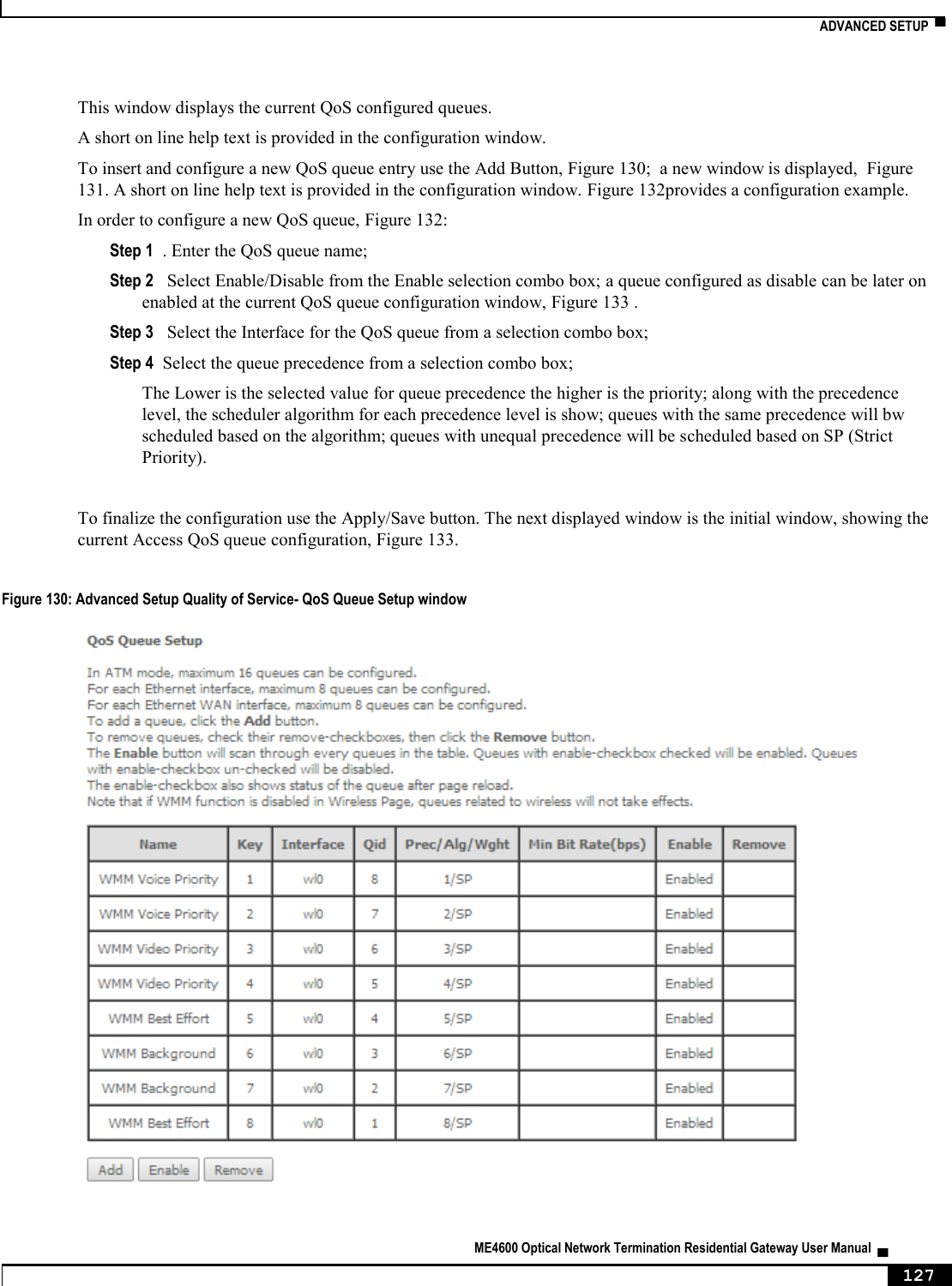
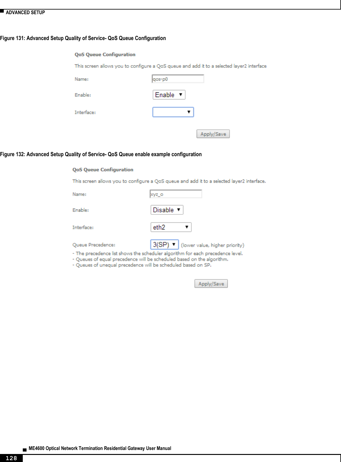
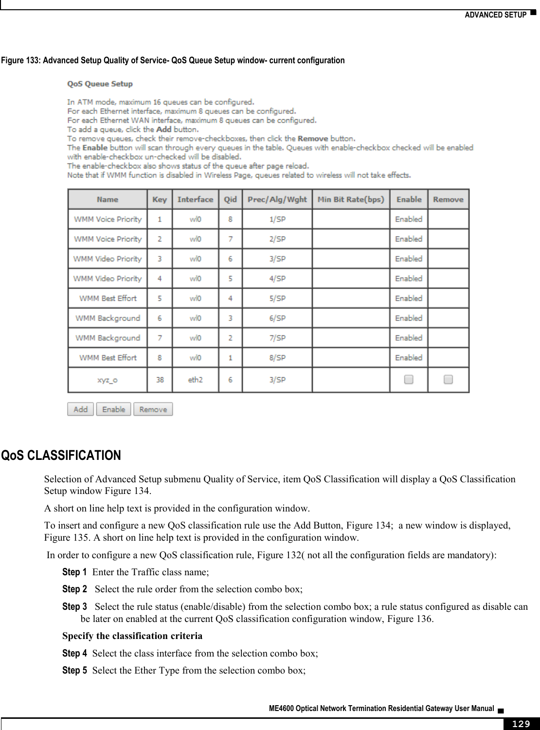
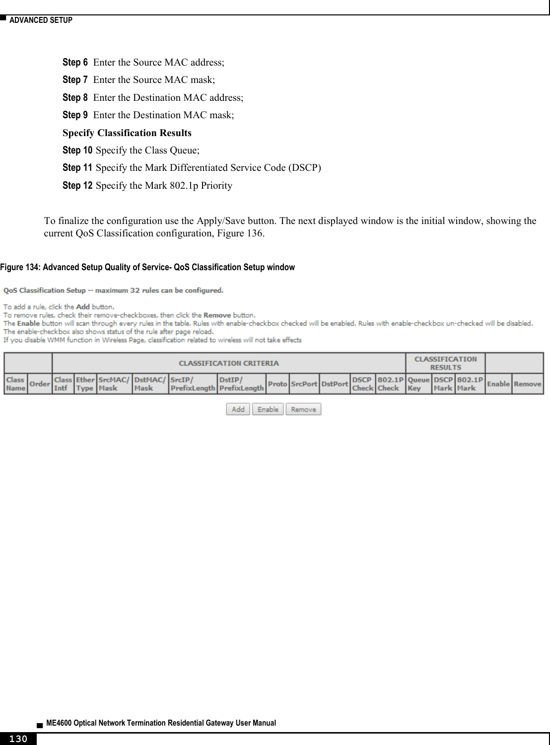
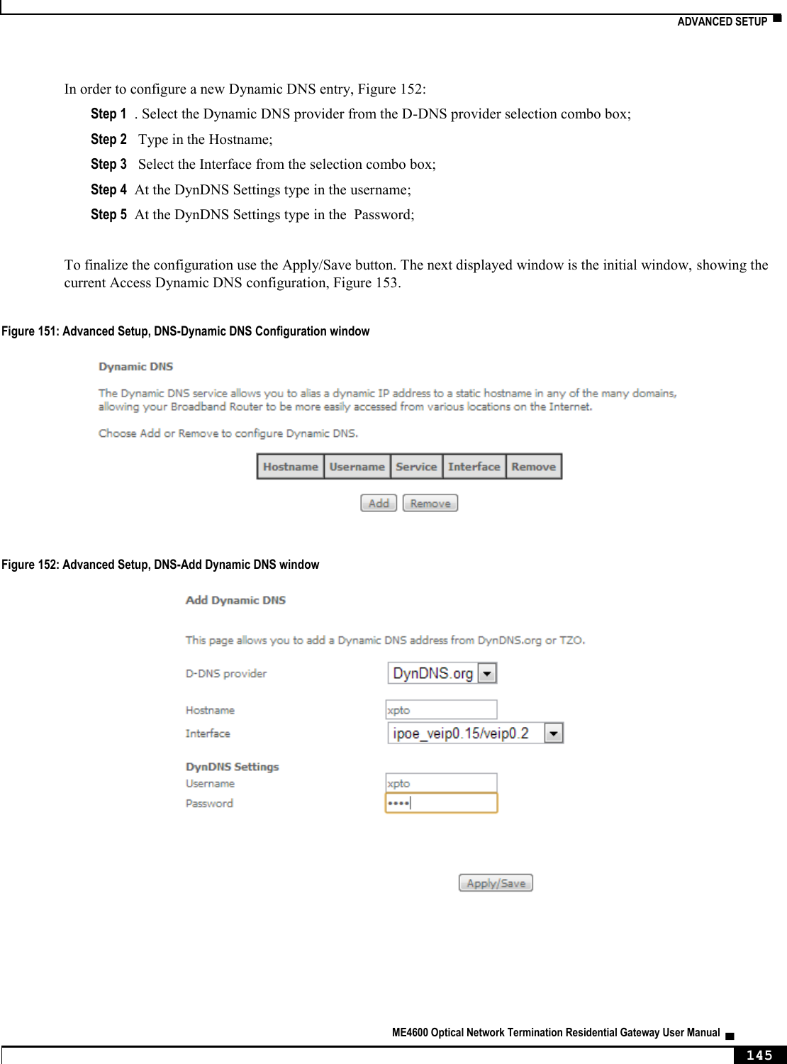
![NODES AND COMMANDS ▀ ME4600 Optical Network Termination Residential Gateway User Manual ▄ 209 “remove” command Table 56: "remove" command information remove remove Description Removes an existing entry Full Path /dns/dynamic/remove Arguments <MANDATORY> --hostname Hostname “qos” node This node allows a user to configure some Qos (Quality of Service) traffic rules. If the QoS option is disabled, then all QoS will be disabled for all interfaces. Besides, the default DSCP mark is used to mark all egress packets that do not match any classification rules. Figure 221: qos node tree + qos[@config, @show] + policer[@create, @remove, @show] + queue[@create, @remove, @show] PERMISSIONS Table 57: qos node and sub-node tree command permissions Command Admin Support User /qos/config Yes Yes No /qos/show Yes Yes No /qos/policer/create Yes Yes No /qos/policer/remove Yes Yes No /qos/policer/show Yes Yes No /qos/queue/create Yes Yes No /qos/queue /remove Yes Yes No /qos/queue /show Yes Yes No](https://usermanual.wiki/Altice-Labs/ME4624-ONTRGW/User-Guide-2568279-Page-211.png)
![▀ NODES AND COMMANDS ▄ ME4600 Optical Network Termination Residential Gateway User Manual 210 “config” command Table 58: "config" command information Name config Description Configures the QoS Full Path /qos/config Arguments <MANDATORY> --qos QoS <enable|disable> [OPTIONAL] --dscp Default DSCP Mark (-1 by default) “policer” sub-node This sub-node is used to add a QoS policer. “create” command Table 59: "create" command information Name create Description Creates a new policer Full Path /qos/policer/create Arguments <MANDATORY> --commited-burst-size Committed Burst Size (bytes) --commited-rate Committed Rate (kbps) --enable Enable <yes|no> --meter Meter type <Simple Token Bucket(1)|Single Rate Three Color(2)|TwoRate Three Color(3)> --name Name [OPTIONAL] --conform-action Conforming Action <Null|DSCP> (Null by default) --dscp DSCP Mark --excess-burst-size Excess Burst Size (bytes) --non-conform-action Nonconforming Action <Null|Drop|DSCP> (Null by default) --partial-conform-action Partial Conforming Action <Null|Drop|DSCP> (Null by default) --peek-burst-size Peak Burst Size (bytes) --peek-rate Peak Rate (kbps)](https://usermanual.wiki/Altice-Labs/ME4624-ONTRGW/User-Guide-2568279-Page-212.png)
![NODES AND COMMANDS ▀ ME4600 Optical Network Termination Residential Gateway User Manual ▄ 211 “remove” command Table 60: "remove" command information remove remove Description Removes an existing policer Full Path /qos/policer/remove Arguments <MANDATORY> --key Key of entry to remove “queue” sub-node This sub-node allows the user to setup a QoS queue. “create” command Table 61: "create" command information Name create Description Creates a new QoS queue Full Path /qos/queue/create Arguments <MANDATORY> --enable[=STRING] Enable <yes|no> --interface Interface --name Name --queue-precedence Queue Precedence (lower value, higher priority) [1-8] --sched-alg Scheduler Algorithm <Strict Priority(SP)|Weighted Round Robin(WRR)> [OPTIONAL] --min-rate Minimum Rate [1-100000 Kbps] (-1 indicates no shaping) (-1 by default) --queue-weigth Queue weight [1-63] “remove” command Table 62: "remove" command information remove remove Description Removes an existing QoS queue](https://usermanual.wiki/Altice-Labs/ME4624-ONTRGW/User-Guide-2568279-Page-213.png)
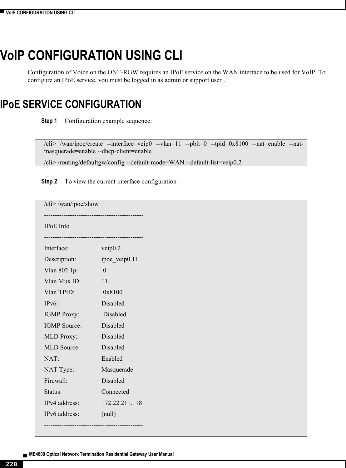
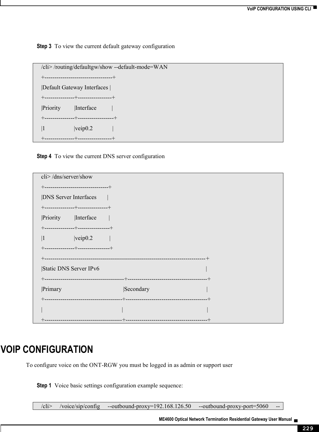
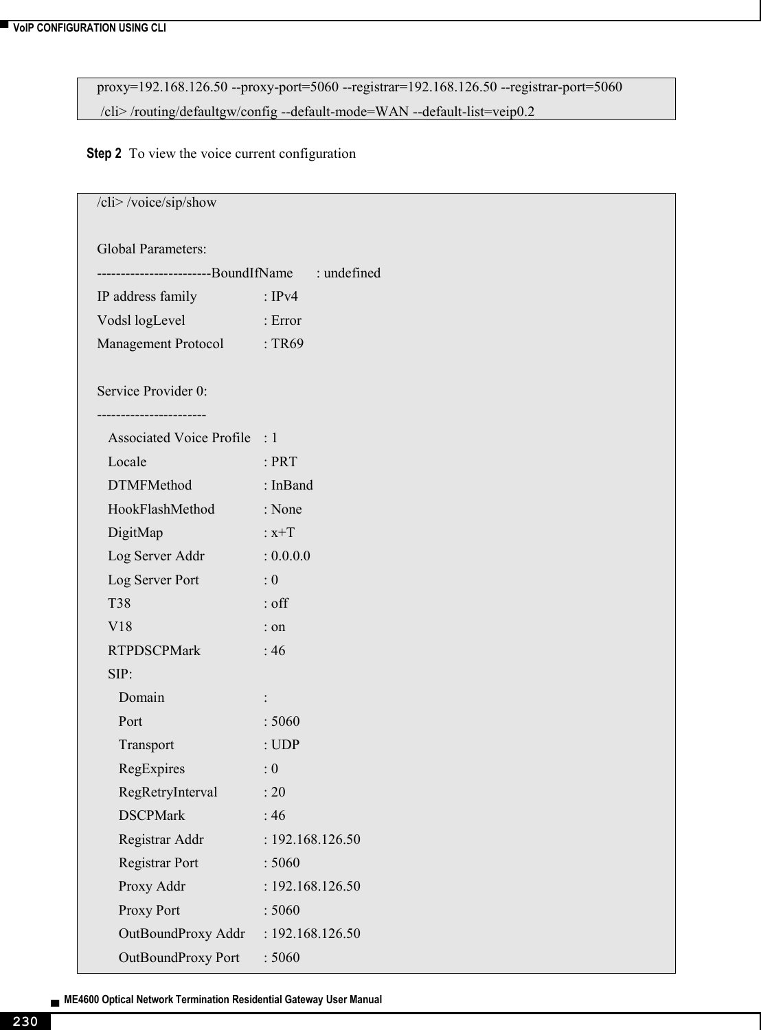
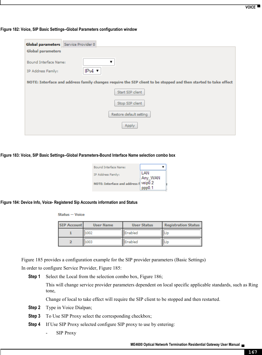
![▀ NODES AND COMMANDS ▄ ME4600 Optical Network Termination Residential Gateway User Manual 212 Full Path /qos/queue/remove Arguments <MANDATORY> --key Key of entry to remove “voice” node This node can be used to configure the voice-related parameters. Only SIP is supported and there are two SIP accounts available. This command also allows the start/stop of the voice application, as well as restoring the settings to their default values. NOTE: At this point, only the configuration of basic voice parameters is supported. Full support must be available in the next versions. Figure 222: voice node tree + voice[@restore-default, @show, @start, @stop] + sip[@config, @show] + account0[@config, @show] + account1[@config, @show] PERMISSIONS Table 63: voice node and sub-node tree command permissions Command Admin Support User /voice/restore-default Yes Yes No /voice/show Yes Yes Yes /voice/start Yes Yes No /voice/stop Yes Yes No /voice/sip/show Yes Yes No /voice/sip/config Yes Yes No /voice/sip /account0/show Yes Yes No /voice/sip /account0/config Yes Yes No /voice/sip /account1/show Yes Yes No /voice/sip /account1/config Yes Yes No](https://usermanual.wiki/Altice-Labs/ME4624-ONTRGW/User-Guide-2568279-Page-214.png)
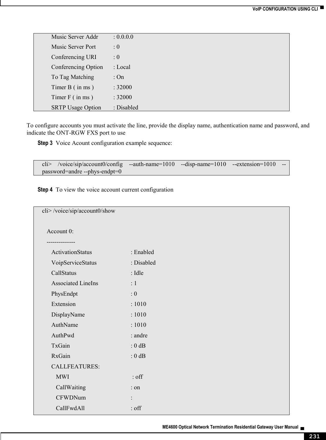
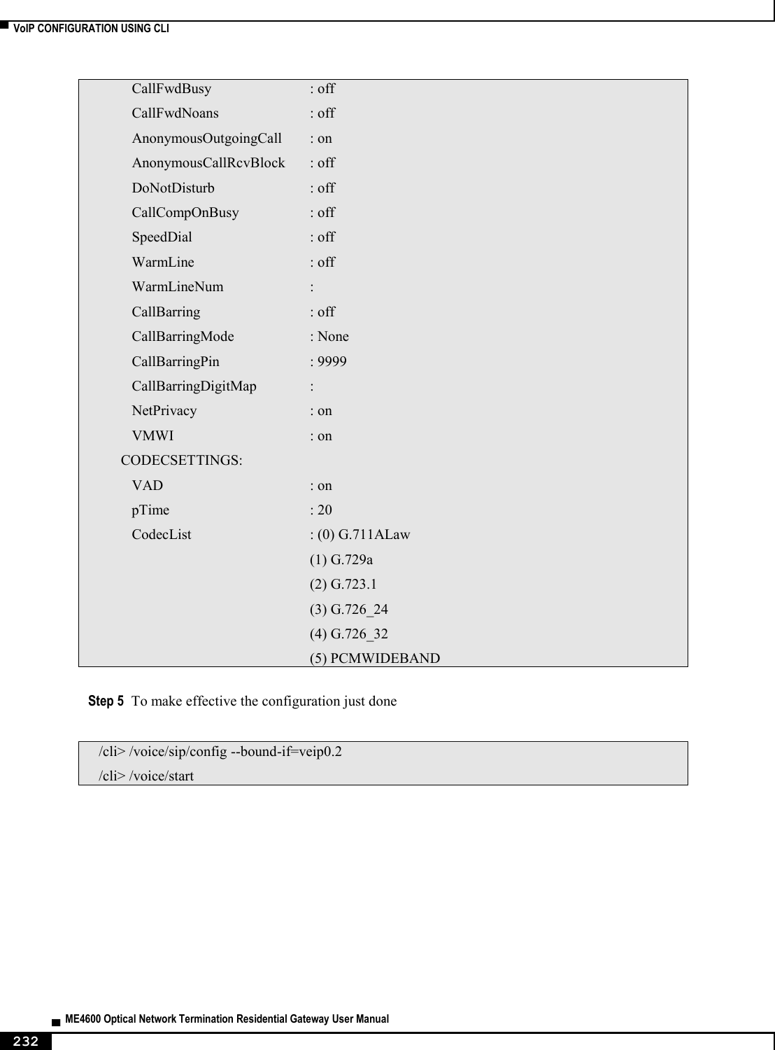
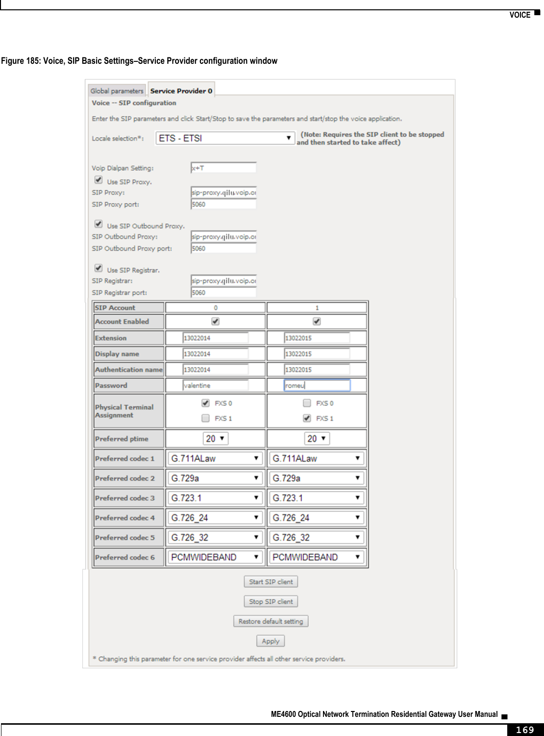
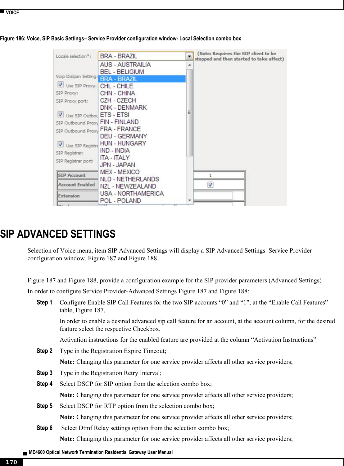
![NODES AND COMMANDS ▀ ME4600 Optical Network Termination Residential Gateway User Manual ▄ 213 “sip” sub-node This sub-node is used to configure the basic SIP settings (non-account-related). “config” command Table 64: "config" command information Name config Description Configures basic SIP settings Full Path /voice/sip/config Arguments [OPTIONAL] --bound-if Bound Interface Name <LAN|Any_WAN| (WAN IfName, e.g. veip0.1) --dialplan Voip Dialpan Setting (x+T by default) --ip-version IP Address Family <IPv4|IPv6> (IPv4 by default) --locale Locale selection (PRT by default) --outbound-proxy SIP Outbound Proxy <hostname|IP> (0.0.0.0 by default) --outbound-proxy-port SIP Outbound Proxy Port (5060 by default) --proxy SIP Proxy <hostname|IP> (0.0.0.0 by default) --proxy-port SIP Proxy Port (5060 by default) --registrar SIP Registrar <hostname|IP> (0.0.0.0 by default) --registrar-port SIP Registrar Port (5060 by default) “account0/1” sub-nodes These sub-nodes allows a user to setup the proper SIP account. “config” command Table 65: "config" command information Name config Description Configures SIP accounts Full Path /voice/sip/account0/config /voice/sip/account1/config Arguments [OPTIONAL] --account Activate line <on|off> (on by default) --auth-name SIP authentication name --codec-list Codec priority list <codec(1)[,codec(2)]> --disp-name SIP Display Name](https://usermanual.wiki/Altice-Labs/ME4624-ONTRGW/User-Guide-2568279-Page-215.png)
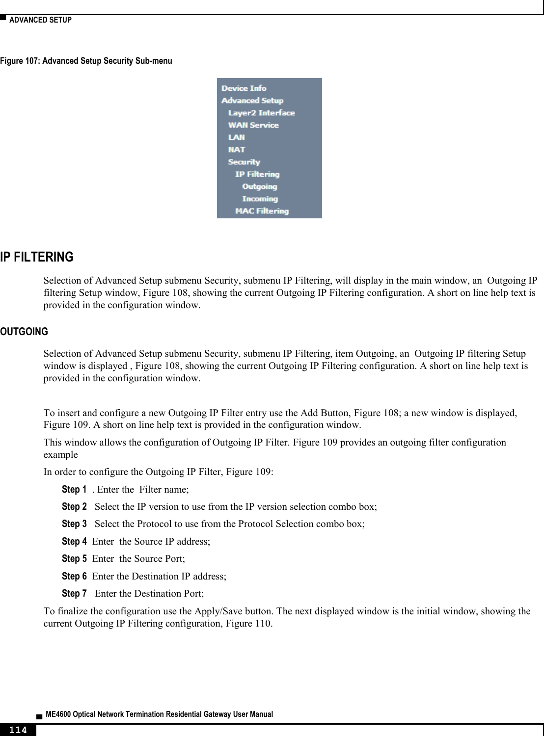
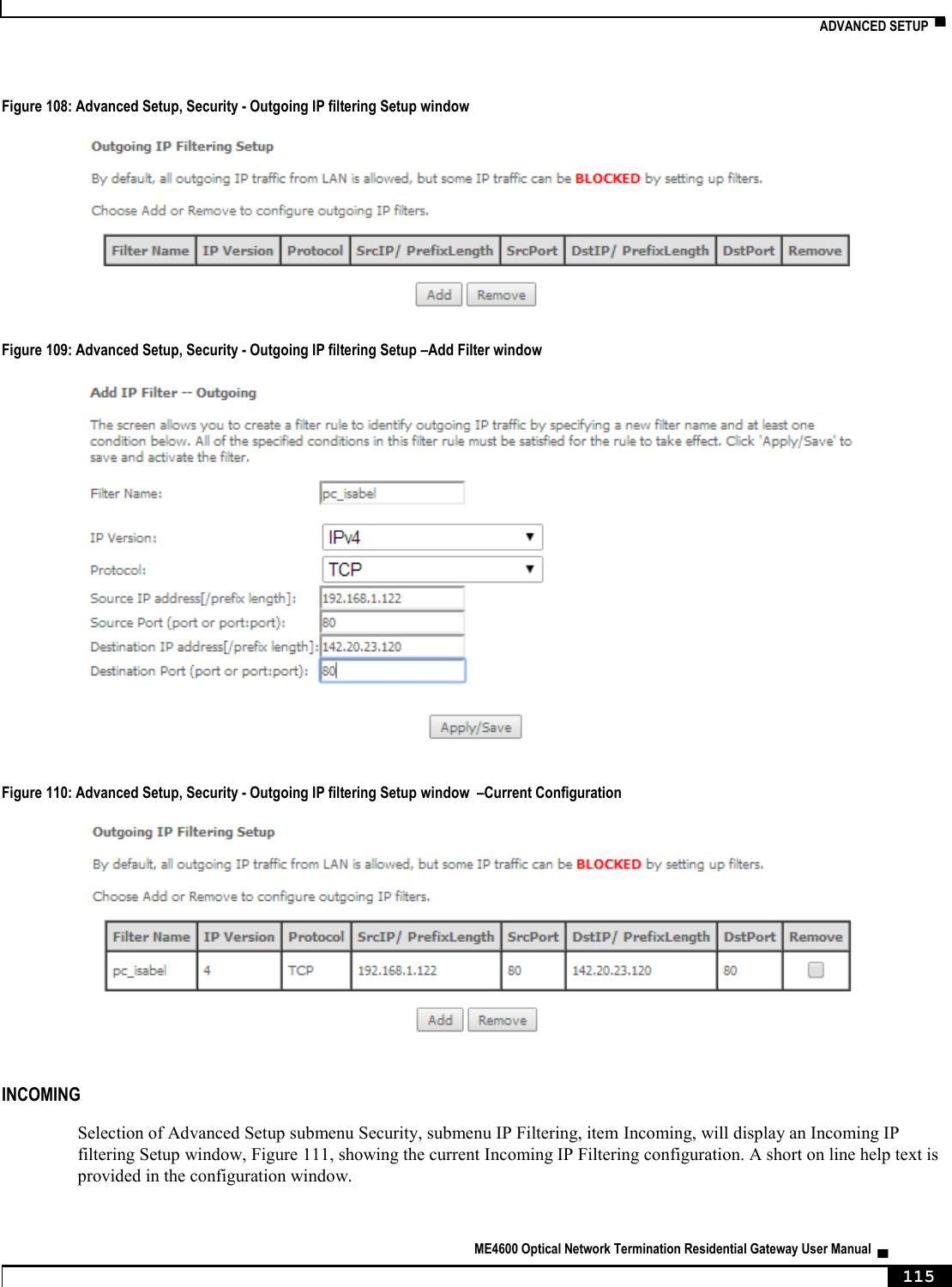
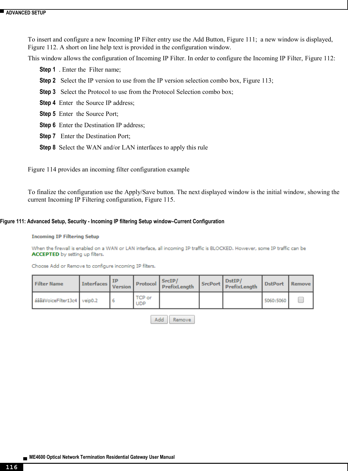
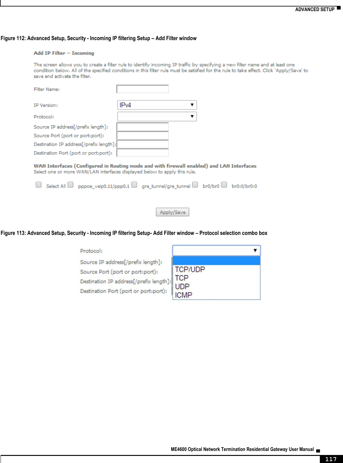
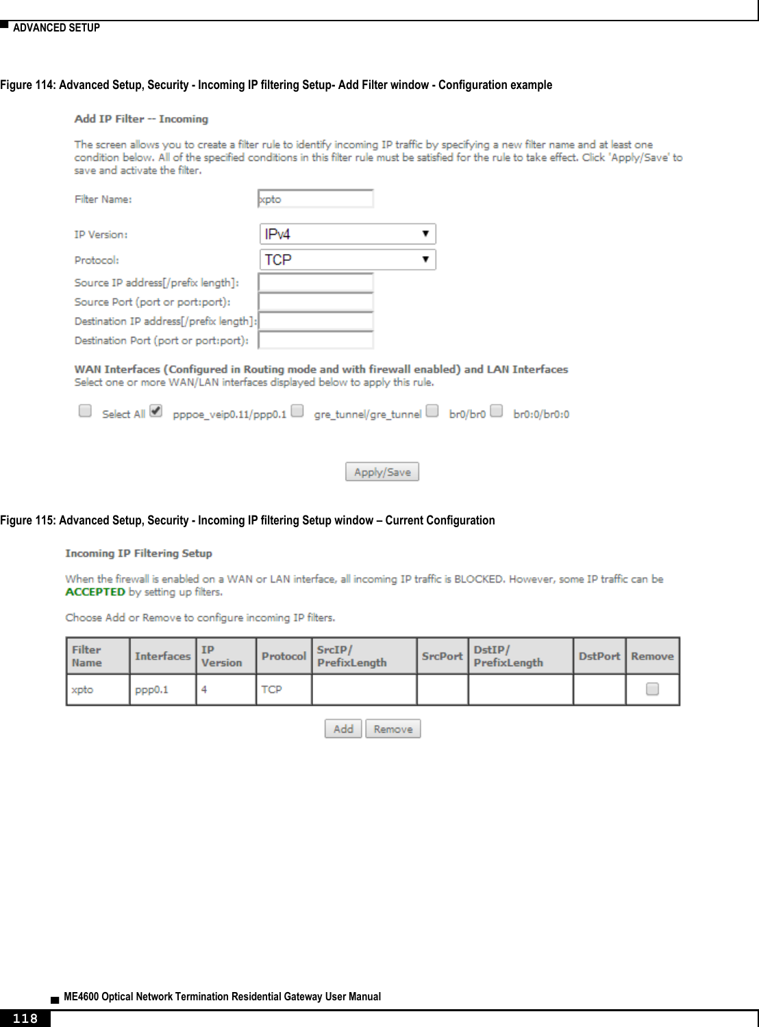
![▀ NODES AND COMMANDS ▄ ME4600 Optical Network Termination Residential Gateway User Manual 214 --extension SIP extension --password SIP authentication password --phys-endpt Physical Terminal Assignment <0|1|0,1> --pref-time Packetization period <10|20|30> (20 by default) “security” node This node allows the configuration of some security settings. Figure 223: security node tree + security[] + ip-filtering[] + incoming[@create, @remove, @show] + outgoing[@create, @remove, @show] PERMISSIONS Table 66: security node and sub-node tree command permissions Command Admin Support User /security/ip-filtering/incoming/create Yes No No /security /ip-filtering/incoming/remove Yes No No /security /ip-filtering/incoming/show Yes No No /security /ip-filtering/outgoing/create Yes No No /security /ip-filtering/outgoing/remove Yes No No /security /ip-filtering/outgoing/show Yes No No “ip-filtering” sub-node “incoming” sub-node When the firewall is enabled on a WAN or LAN interface, all incoming IP traffic is BLOCKED. However, some IP traffic can be ACCEPTED by setting up filters. The aim of this sub-node is to allow the configuration of those filters. “create” command](https://usermanual.wiki/Altice-Labs/ME4624-ONTRGW/User-Guide-2568279-Page-216.png)
![NODES AND COMMANDS ▀ ME4600 Optical Network Termination Residential Gateway User Manual ▄ 215 Table 67: "create" command information Name create Description Creates a filter Full Path /security/ip-filtering/incoming/create Arguments <MANDATORY> --dest-ip Destination IP address --dest-port Destination port --interfaces WAN Interfaces (configured in Routing mode and with firewall enabled) and LAN interfaces <ALL or intf1[|intf2|...]> --ip-version IP version <IPv4|IPv6> --name Filter name --protocol Protocol <TCP/UDP|TCP|UDP|ICMP> --src-ip Source IP address --src-port Source port “remove” command Table 68: "remove" command information remove remove Description Removes an existing filter Full Path /security/ip-filtering/incoming/remove Arguments <MANDATORY> --name-to-rmv Filter name to remove “outgoing” sub-node By default, all outgoing IP traffic from LAN is allowed, but some IP traffic can be BLOCKED by setting up filters. The aim of this sub-node is to allow the configuration of those filters. “create” command Table 69: "create" command information Name create Description Creates a filter Full Path /security/ip-filtering/outgoing/create Arguments](https://usermanual.wiki/Altice-Labs/ME4624-ONTRGW/User-Guide-2568279-Page-217.png)
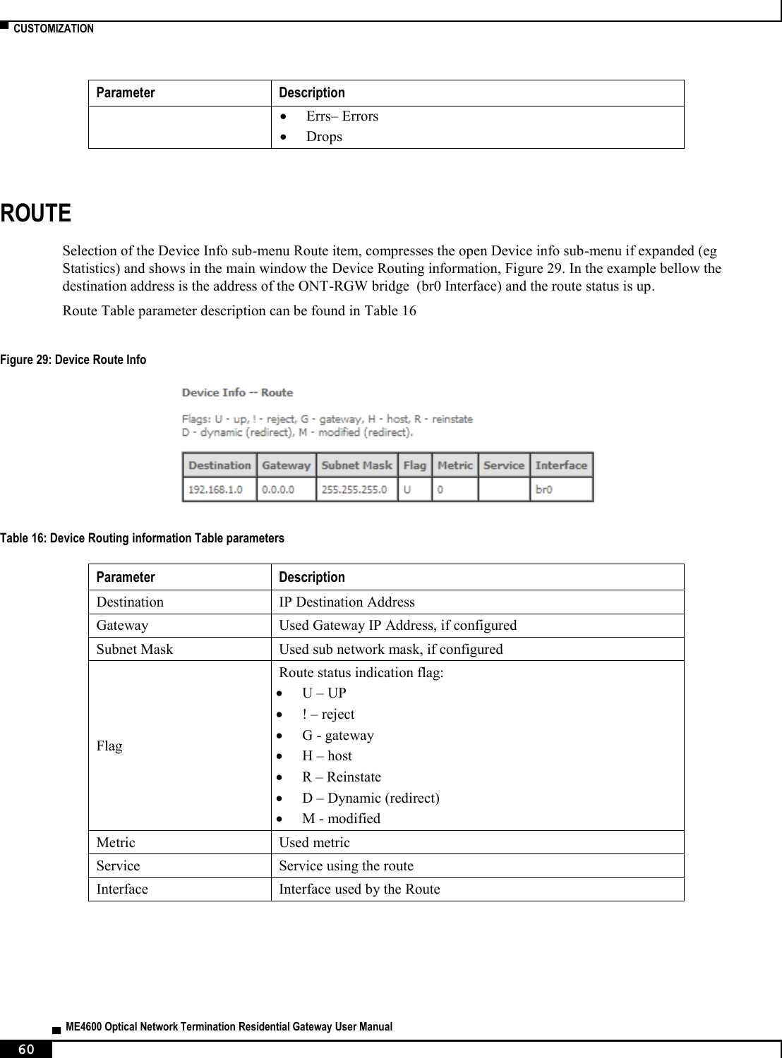
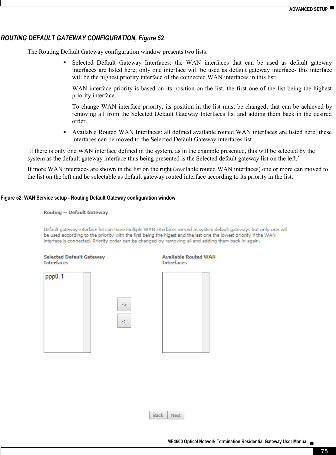
![▀ NODES AND COMMANDS ▄ ME4600 Optical Network Termination Residential Gateway User Manual 216 <MANDATORY> --dest-ip Destination IP address --dest-port Destination port --ip-version IP version <IPv4|IPv6> --name Filter name --protocol Protocol <TCP/UDP|TCP|UDP|ICMP> --src-ip Source IP address --src-port Source port “remove” command Table 70: "remove" command information remove remove Description Removes an existing filter Full Path /security/ip-filtering/outgoing/remove Arguments <MANDATORY> --name-to-rmv Filter name to remove “routing” node This node allows the configuration of some routing settings. Figure 224: routing node tree + routing[] + defaultgw[@config, @show] + static-route[@config, @remove, @show] PERMISSIONS Table 71: routing node and sub-node tree command permissions Command Admin Support User /routing/defaultgw/config Yes Yes No /routing /defaultgw /show Yes Yes No /routing /static-route/config Yes Yes No /routing /static-route/remove Yes Yes No](https://usermanual.wiki/Altice-Labs/ME4624-ONTRGW/User-Guide-2568279-Page-218.png)
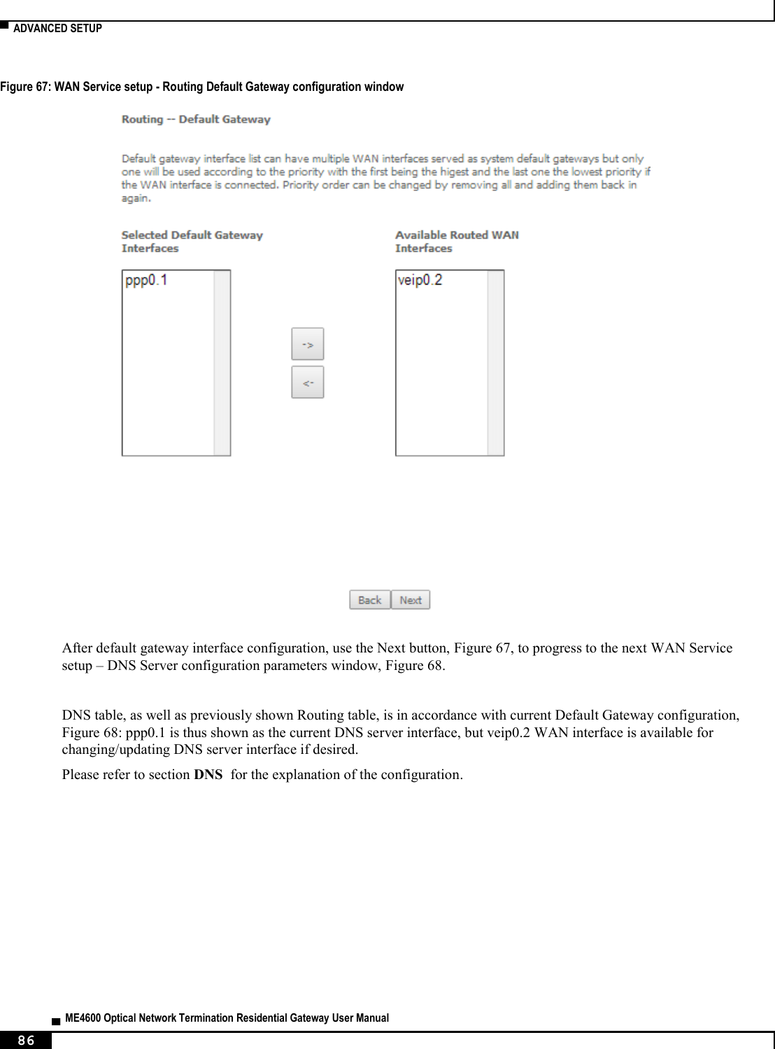
![NODES AND COMMANDS ▀ ME4600 Optical Network Termination Residential Gateway User Manual ▄ 217 Command Admin Support User /routing /static-route/show Yes Yes Yes “defaultgw” sub-node Default gateway interface list can have multiple WAN interfaces served as system default gateways but only one will be used according to the priority with the first being the highest and the last one the lowest priority if the WAN interface is connected. “config” command Table 72: "config" command information Name config Description Enters the default gateway interface list Full Path /routing/defaultgw/config Arguments <MANDATORY> --default-mode Default gateway mode <WAN/LAN> [OPTIONAL] --default-gw6-ifc Default WAN IPv6 gateway --default-list Selected Default Gateway Interfaces <intf1,...intfN> --lan-address Default Gateway IP Address --lan-bridge LAN Interface (Default by default) “static-route” sub-node This sub-node allows the user to configure static routes. “config” command Table 73: "config" command information Name config Description Creates a static route Full Path /routing/static-route/config Arguments <MANDATORY> --dest-ip Destination IP address/prefix length --gw-address Gateway IP address](https://usermanual.wiki/Altice-Labs/ME4624-ONTRGW/User-Guide-2568279-Page-219.png)
![▀ NODES AND COMMANDS ▄ ME4600 Optical Network Termination Residential Gateway User Manual 218 --interface Interface [OPTIONAL] --ip-version IP Version <IPv4|IPv6> (IPv4 by default) --metric Metric “remove” command Table 74: "remove" command information Name remove Description Removes an existing static route Full Path /routing/static-route/remove Arguments <MANDATORY> --dest-ip Destination IP address/prefix length “multicast” node This node allows the user to setup multicast. It can be configured some IGMP and MLD parameters. Figure 225: multicast node tree + multicast[@config, @show] PERMISSIONS Table 75: multicast node command permissions Command Admin Support User /multicast/config Yes Yes No /multicast/show Yes Yes No “config” command Table 76: "config" command information Name config Description Configures multicast](https://usermanual.wiki/Altice-Labs/ME4624-ONTRGW/User-Guide-2568279-Page-220.png)
![NODES AND COMMANDS ▀ ME4600 Optical Network Termination Residential Gateway User Manual ▄ 219 Full Path /multicast/config Arguments [OPTIONAL] --igmp-fast-leave IGMP Fast Leave <enable|disable> (enable by default) --igmp-last-member-query-int IGMP Last Member Query Interval (10 by default) --igmp-max-groups IGMP Maximum Multicast Groups (25 by default) --igmp-max-members IGMP Maximum Multicast Group Members (25 by default) --igmp-max-sources IGMP Maximum Multicast Data Sources (for IGMPv3) (10 by default) --igmp-query-int IGMP Query Interval (125 by default) --igmp-query-resp-int IGMP Query Response Interval (10 by default) --igmp-rv IGMP Robustness value (2 by default) --igmp-version IGMP Default Version <1|2|3> (2 by default) --mld-fast-leave MLD Fast Leave <enable|disable> (enable by default) --mld-last-member-query-int MLD Last Member Query Interval (10 by default) --mld-max-groups MLD Maximum Multicast Groups (10 by default) --mld-max-members MLD Maximum Multicast Group Members (10 by default) --mld-max-sources MLD Maximum Multicast Data Sources (for MLDv2) (10 by default) --mld-query-int MLD Query Interval (125 by default) --mld-query-resp-int MLD Query Response Interval (10 by default) --mld-rv MLD Robustness value (2 by default) --mld-version MLD Default Version <1|2> (2 by default) --precedence Multicast precedence <Disable|[1,8]> (lower value, higher priority) (Disable by default) “diagnostics” node This node allows the user to check the current status of the equipment LAN and WLAN interfaces. Figure 226: diagnostics node tree + diagnostics [@show] PERMISSIONS Table 77: diagnostics node command permissions Command Admin Support User /diagnostics/show Yes Yes Yes](https://usermanual.wiki/Altice-Labs/ME4624-ONTRGW/User-Guide-2568279-Page-221.png)
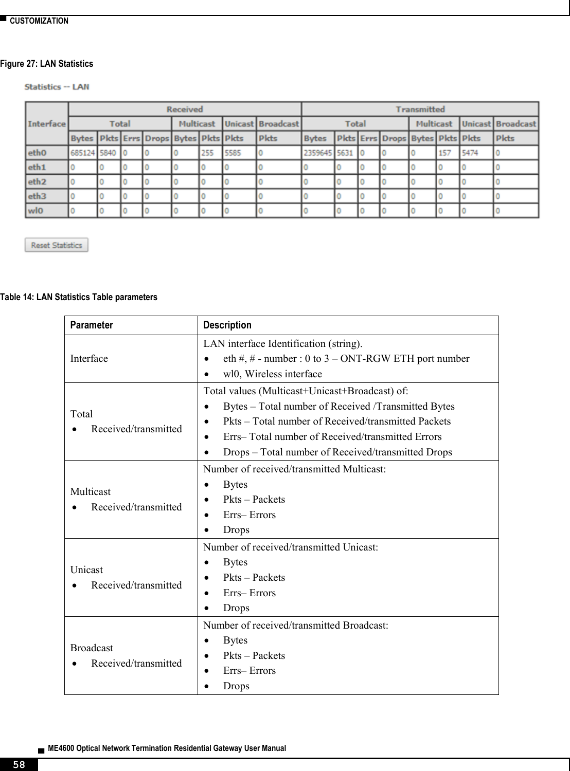
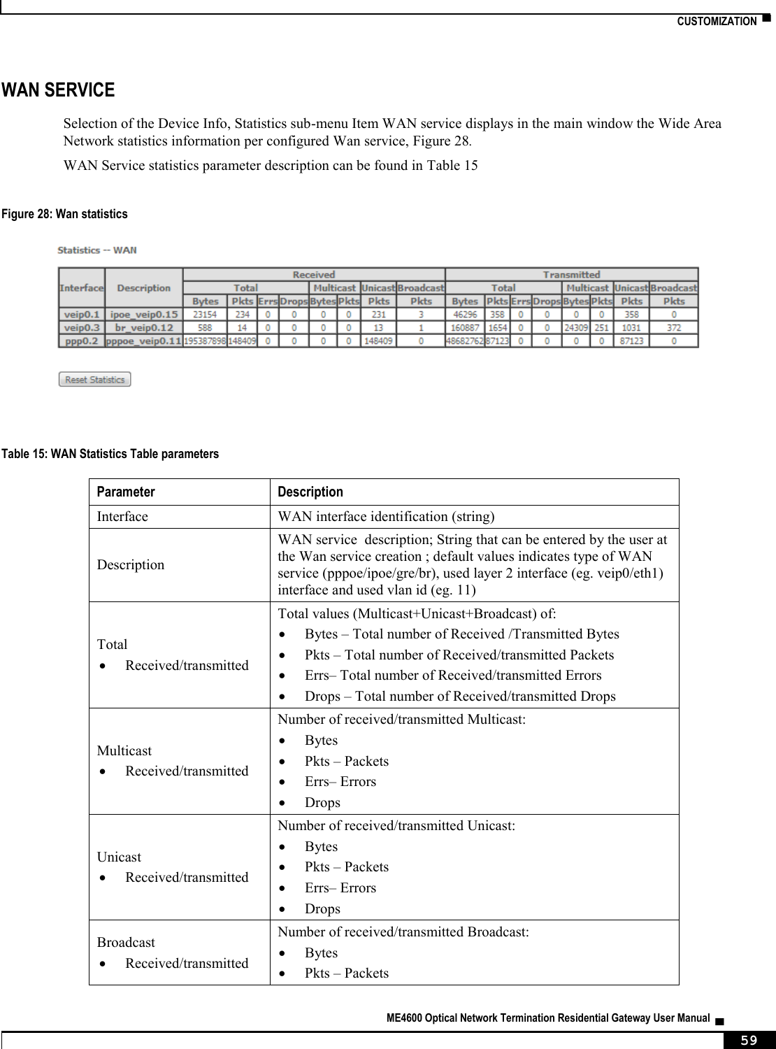
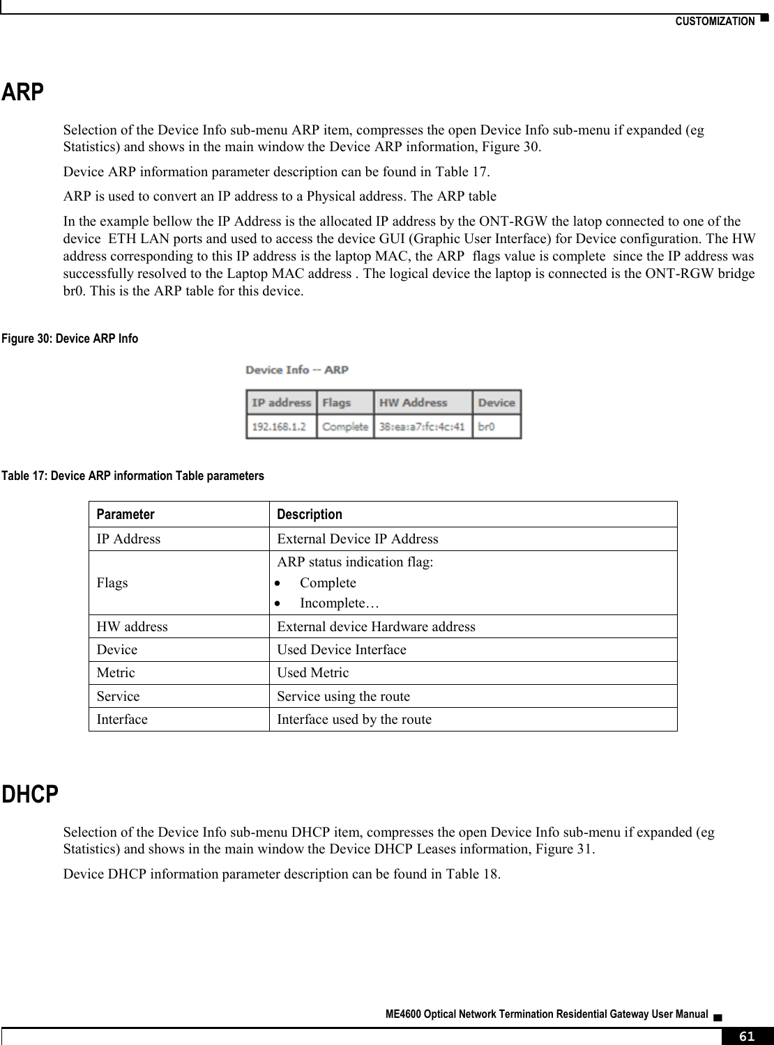
![▀ NODES AND COMMANDS ▄ ME4600 Optical Network Termination Residential Gateway User Manual 220 “arp” node This node displays the ARP (Address Resolution Protocol) table. Figure 227: arp node tree + arp [@show] PERMISSIONS Table 78: arp node command permissions Command Admin Support User /arp/show Yes Yes Yes “device-info” node This node displays general info about the device (such as serial number, MAC address, software version). Figure 228: device-info node tree + device-info[@show] PERMISSIONS Table 79: device-info node command permissions Command Admin Support User /device-info/show Yes Yes Yes “statistics” node This node allows the user to view and reset the current WAN/LAN/optical statistics on the device. The –option argument is a mandatory argument to all the commands in this tree and is used to select the type of packets to show, Received, Transmitted or all. The following argument values can be used: <received|transmitted|all>. Figure 229: statistics node tree + statistics[]](https://usermanual.wiki/Altice-Labs/ME4624-ONTRGW/User-Guide-2568279-Page-222.png)
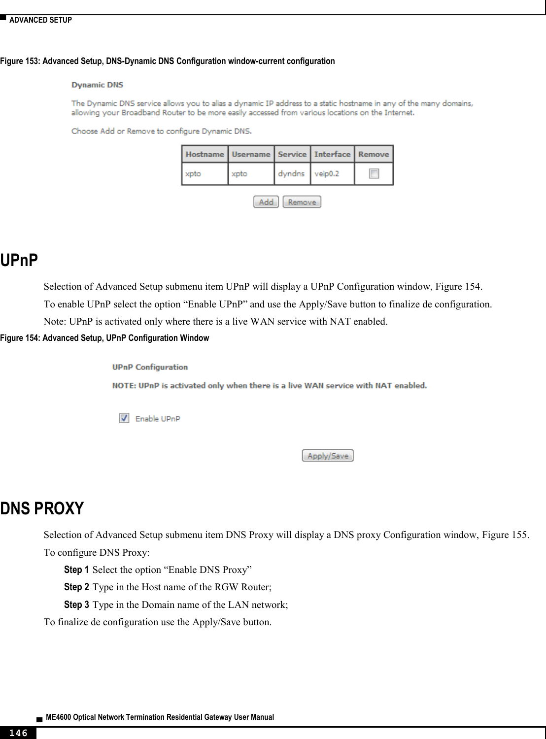
![NODES AND COMMANDS ▀ ME4600 Optical Network Termination Residential Gateway User Manual ▄ 221 + lan[@reset, @show] + optical[@reset, @show] + wan[@reset, @show] PERMISSIONS Table 80: statistics node and sub-node tree command permissions Command Admin Support User /statistics/lan/reset Yes Yes Yes /statistics/lan/show Yes Yes Yes /statistics/optical/reset Yes Yes Yes /statistics/optical/show Yes Yes Yes /statistics/wan/reset Yes Yes Yes /statistics/wan/show Yes Yes Yes “dhcp” node A DHCP-enabled client obtains a lease for an IP address from a DHCP server. Before the lease expires, the DHCP server must renew the lease for the client or the client must obtain a new lease. This node shows the DHCP leases table. Figure 230: dhcp node tree + dhcp[@show] PERMISSIONS Table 81: dhcp node and sub-node tree command permissions Command Admin Support User /dhcp/show Yes Yes Yes “upnp” node This node is used to enable/disable UPnP (Universal Plug and Play). UPnP is activated only when there is a live WAN service with NAT enabled. Figure 231: upnp node tree + upnp[@config, @show]](https://usermanual.wiki/Altice-Labs/ME4624-ONTRGW/User-Guide-2568279-Page-223.png)
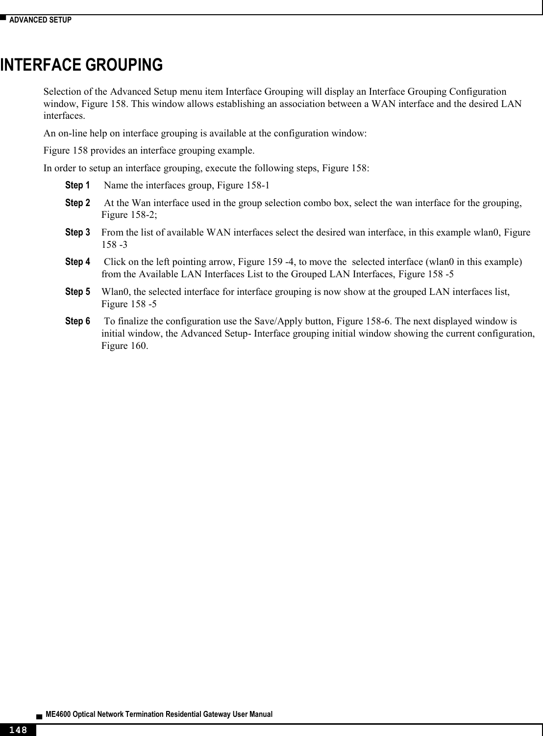
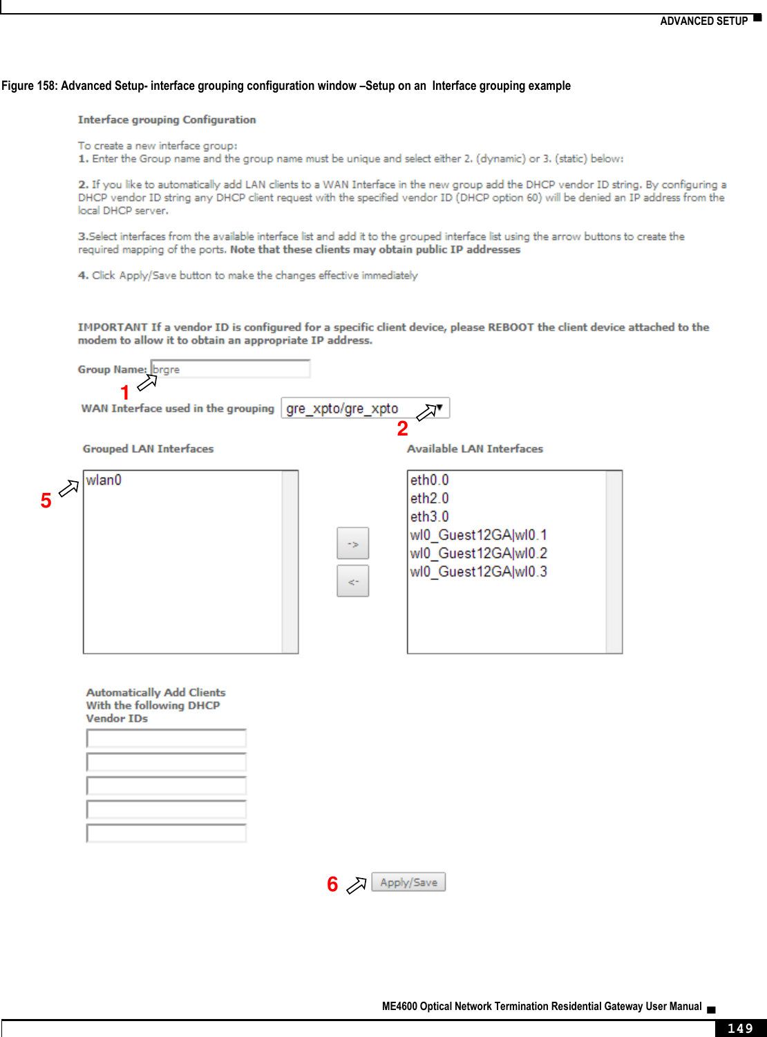
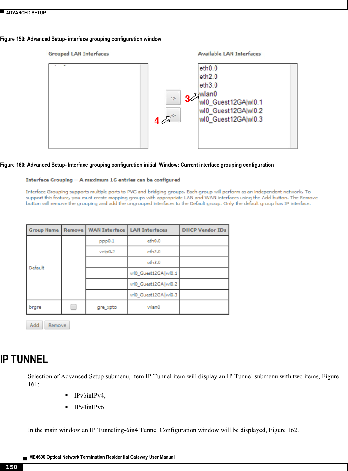
![▀ NODES AND COMMANDS ▄ ME4600 Optical Network Termination Residential Gateway User Manual 222 PERMISSIONS Table 82: upnp node command permissions Command Admin Support User /upnp/config Yes Yes No /upnp/show Yes Yes No “config” command Table 83: "config" command information Name config Description Configures UPnP Full Path /upnp/config Arguments <MANDATORY> --enable Enable UPnP <yes|no> “intf-grouping” node Interface Grouping supports multiple ports to PVC and bridging groups. Each group will perform as an independent network. Figure 232: intf-grouping node tree + intf-grouping[@config, @remove, @show] PERMISSIONS Table 84: intf-grouping node command permissions Command Admin Support User /intf-grouping/config Yes No No /intf-grouping/remove Yes No No /intf-grouping/show Yes No No](https://usermanual.wiki/Altice-Labs/ME4624-ONTRGW/User-Guide-2568279-Page-224.png)
![NODES AND COMMANDS ▀ ME4600 Optical Network Termination Residential Gateway User Manual ▄ 223 “config” command Table 85: "config" command information Name config Description Configures interface grouping Full Path /intf-grouping/config Arguments <MANDATORY> --group-name Group name --lan-intf LAN interfaces to group <intf1[|intf2|...]> [OPTIONAL] --routing-mode Routing mode <enable|disable> (disable by default) --vendor-id0 Automatically Add Clients With the following DHCP Vendor ID 0 --vendor-id1 Automatically Add Clients With the following DHCP Vendor ID 1 --vendor-id2 Automatically Add Clients With the following DHCP Vendor ID 2 --vendor-id3 Automatically Add Clients With the following DHCP Vendor ID 3 --vendor-id4 Automatically Add Clients With the following DHCP Vendor ID 4 --wan-intf WAN Interface used in the grouping (None by default) “remove” command Table 86: "remove" command information Name remove Description Removes an existing interface grouping entry Full Path /intf-grouping/remove Arguments <MANDATORY> --group-name-to-rmv Group name to remove](https://usermanual.wiki/Altice-Labs/ME4624-ONTRGW/User-Guide-2568279-Page-225.png)
![▀ NODES AND COMMANDS ▄ ME4600 Optical Network Termination Residential Gateway User Manual 224 “management” node The aim of this section is to allow users to perform management functions over the ONT-RGW. Figure 233: management node tree + management[@backup, @reboot, @restore-default, @update-settings, @update-software] + access-control[@change-pw] + new-users[@create, @remove, @show] + security-log[@reset, @show] + snmp[@config, @show] + system-log[@config, @show] PERMISSIONS Table 87: management node and sub-nodes command permissions Command Admin Support User /management/reboot Yes Yes No /management /restore-default Yes Yes No /management /backup Yes Yes No /management /update-settings Yes Yes No /management /update-software Yes Yes No /management /access-control/change-pw Yes Yes Yes /management /access-control/new-users/create Yes Yes No /management /access-control/ new-users/remove Yes Yes No /management /access-control/ new-users/show Yes Yes No /management /security-log/reset Yes Yes No /management /security-log/show Yes Yes No /management /snmp/config Yes Yes No /management /snmp/show Yes Yes No /management /system-log/config Yes Yes Yes /management /system-log/show Yes Yes Yes “backup” command Table 88: "backup" command information Name backup Description Backups settings (saves a file named backupsettings.conf on the TFTP address)](https://usermanual.wiki/Altice-Labs/ME4624-ONTRGW/User-Guide-2568279-Page-226.png)
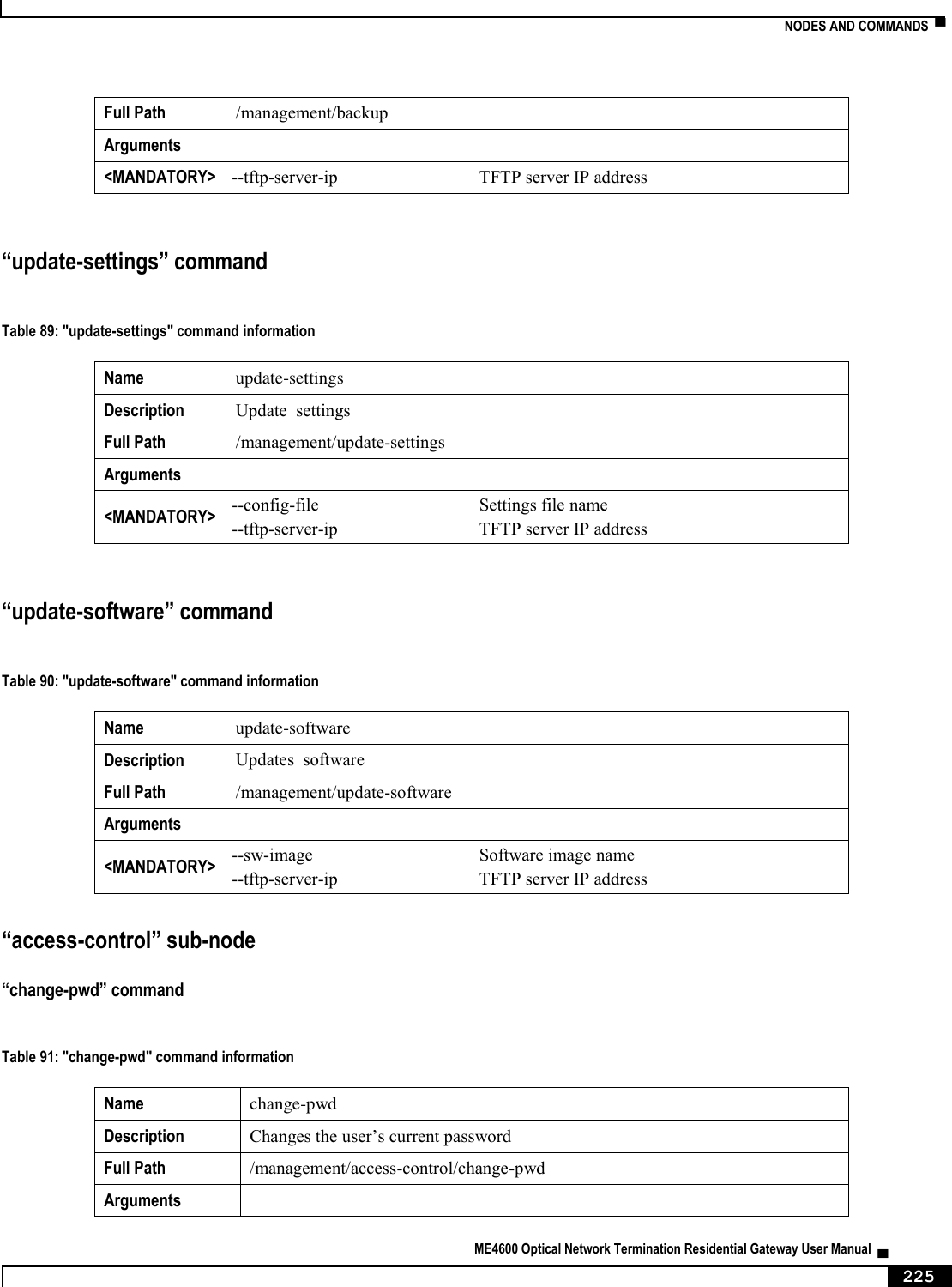
![▀ NODES AND COMMANDS ▄ ME4600 Optical Network Termination Residential Gateway User Manual 226 <MANDATORY> --new-pw New password --old-pw Old password --username User name “new-users” sub-node This sub-node allows the creation and removal of new users. It also allows viewing new users already configured. “create” command Table 92: "create" command information Name create Description Creates a new user Full Path /management/access-control/new-users/create Arguments <MANDATORY> --password Password --permissions-level Permissions level <admin|support|user> --username User name “remove” command Table 93: "create" command information Name remove Description Removes existing users Full Path /management/access-control/new-users/remove Arguments <MANDATORY> --user-to-rmv List of usernames to remove <name1[,name2,...]> “security-log” sub-node This sub-node allows the user to see and to reset the security log. “system-log” sub-node This sub-node allows the user to see and to reset the system log. “snmp” sub-node This sub-node allows the user to see the configured SNMP client parameters, as well as configure those parameters.](https://usermanual.wiki/Altice-Labs/ME4624-ONTRGW/User-Guide-2568279-Page-228.png)
![NODES AND COMMANDS ▀ ME4600 Optical Network Termination Residential Gateway User Manual ▄ 227 “config” command Table 94: "config" command information Name config Description Configures the SNMP client Full Path /management/snmp/config Arguments <MANDATORY> --agent SNMP Agent <enable|disable> [OPTIONAL] --auth-mode SNMPv3 Authentication Mode <MD5|SHA> (MD5 by default) --auth-passphrase SNMPv3 Authentication Passphrase (password by default) --auth-trap SNMPv3 Authentication Trap <Enable|Disable> (Disable by default) --permissions SNMPv3 Permissions <R|RW> (R by default) --priv-mode SNMPv3 Privacy Mode <None|DES|AES> (None by default) --priv-passphare SNMPv3 Privacy Passphrase --read-community SNMPv2 Read community (public by default) --set-community SNMPv2 Set community (private by default) --system-contact System contact --system-location System location --system-name System name --trap-manager-ip SNMPv3 Trap Manager IP Address (0.0.0.0 by default) --trap-manager-ip SNMPv2 Trap Manager IP (0.0.0.0 by default) --username SNMPv3 Username (default by default)](https://usermanual.wiki/Altice-Labs/ME4624-ONTRGW/User-Guide-2568279-Page-229.png)