Altiostar Networks 22490500 LTE Band 5 Remote Radio Head User Manual Product Description and Installation Guide
Altiostar Networks, Inc. LTE Band 5 Remote Radio Head Product Description and Installation Guide
Product Description and Installation Guide
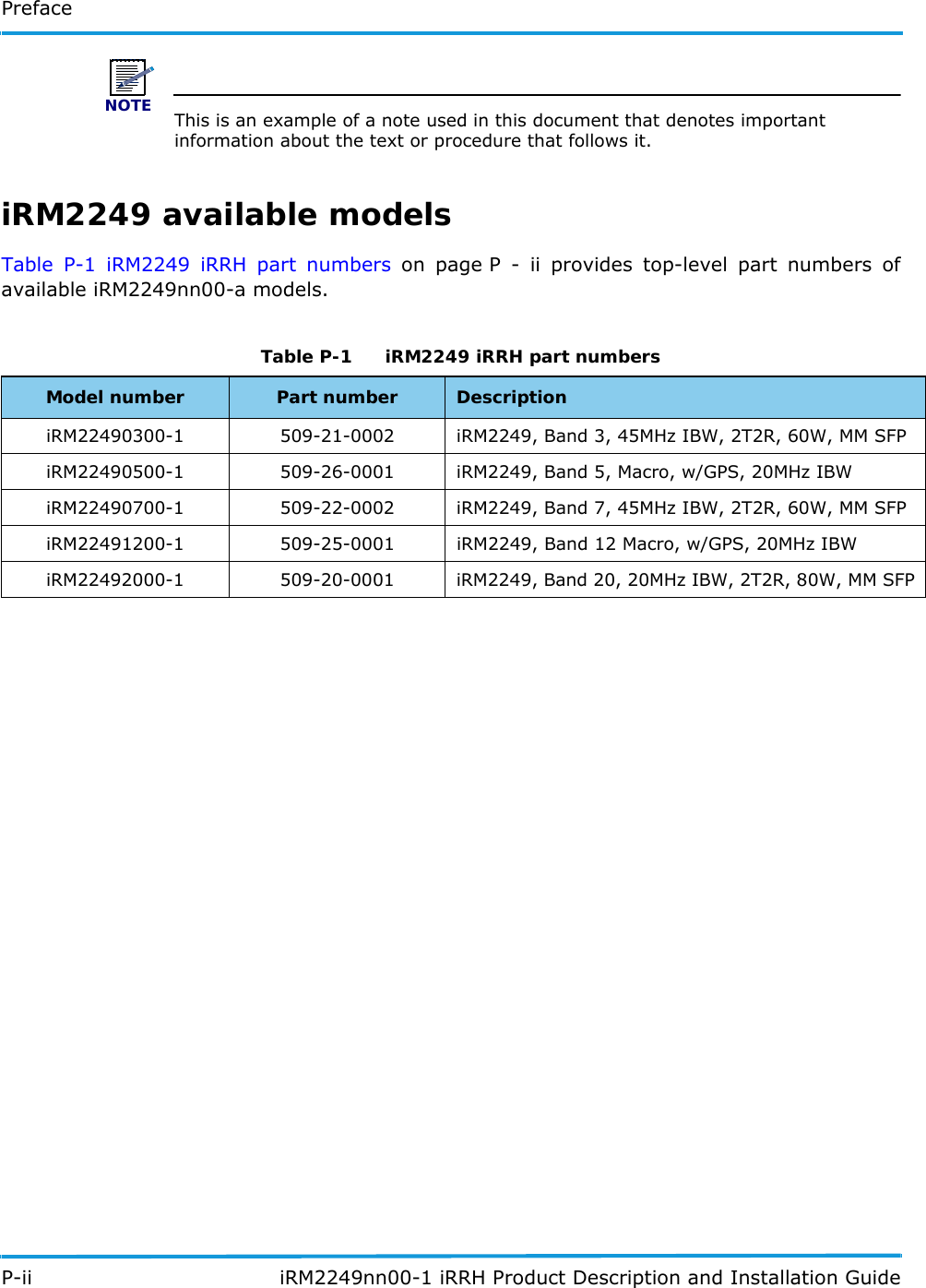


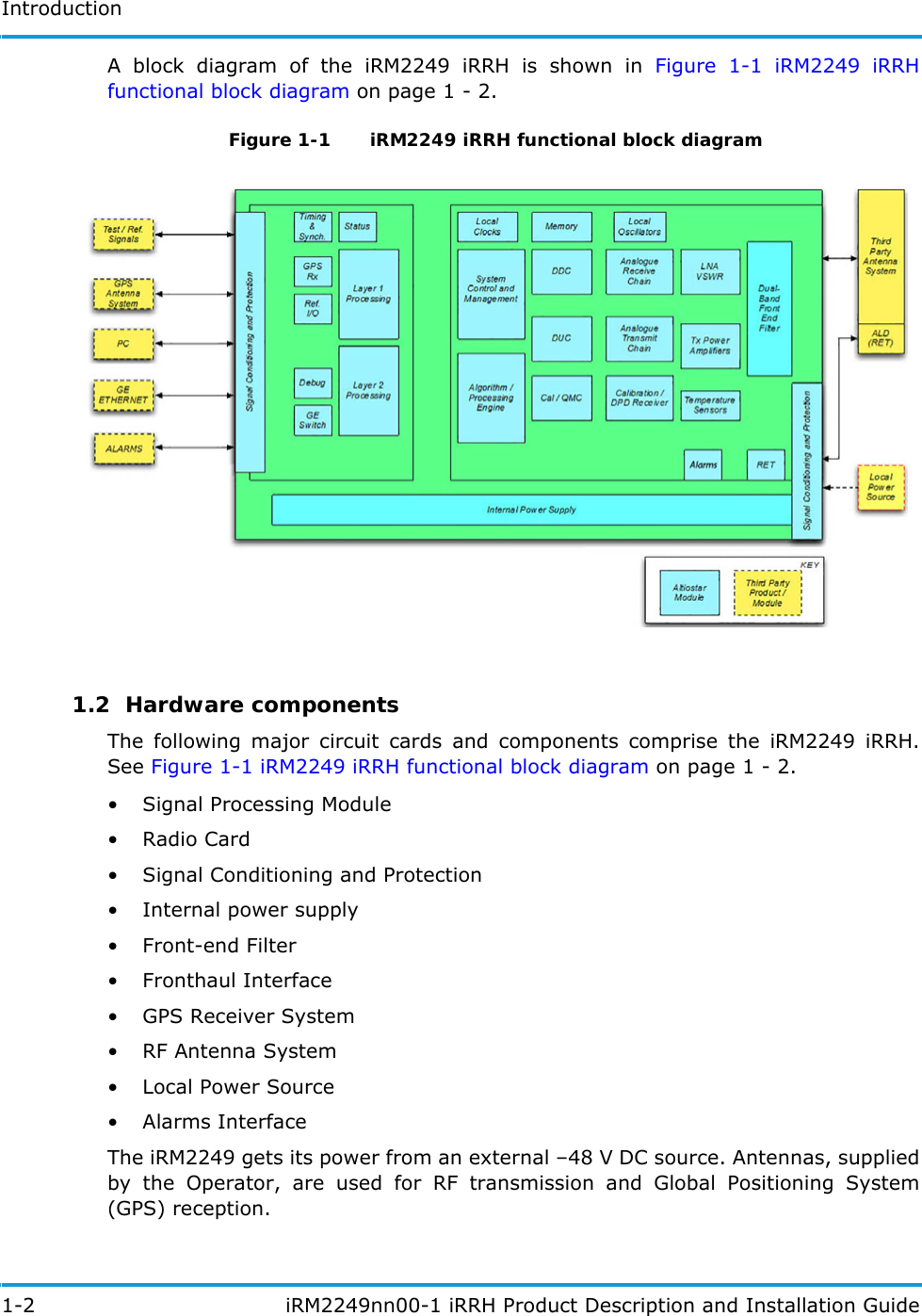
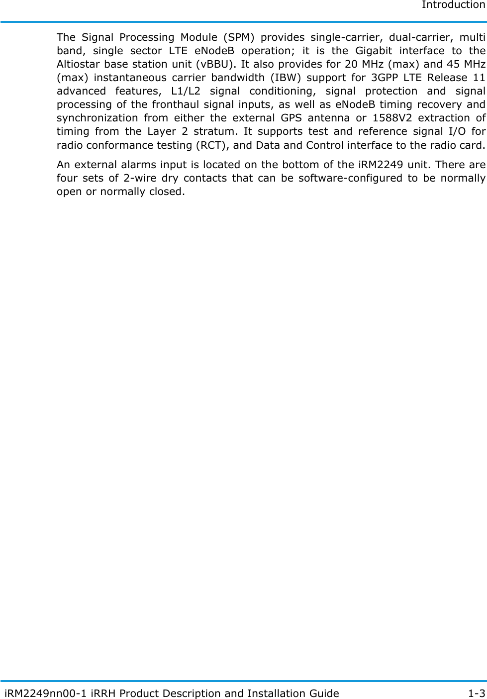

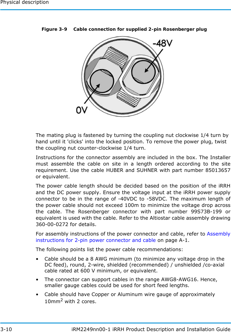
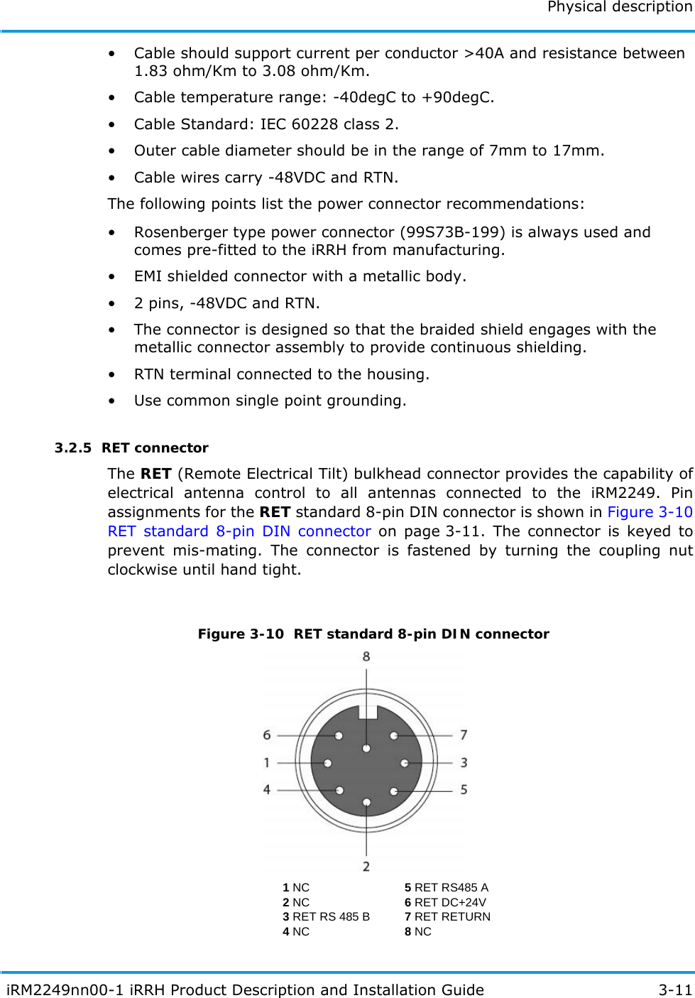
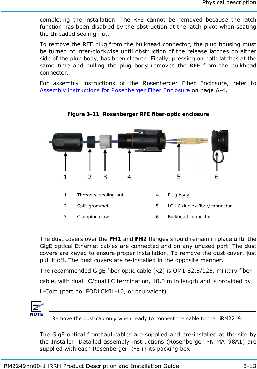
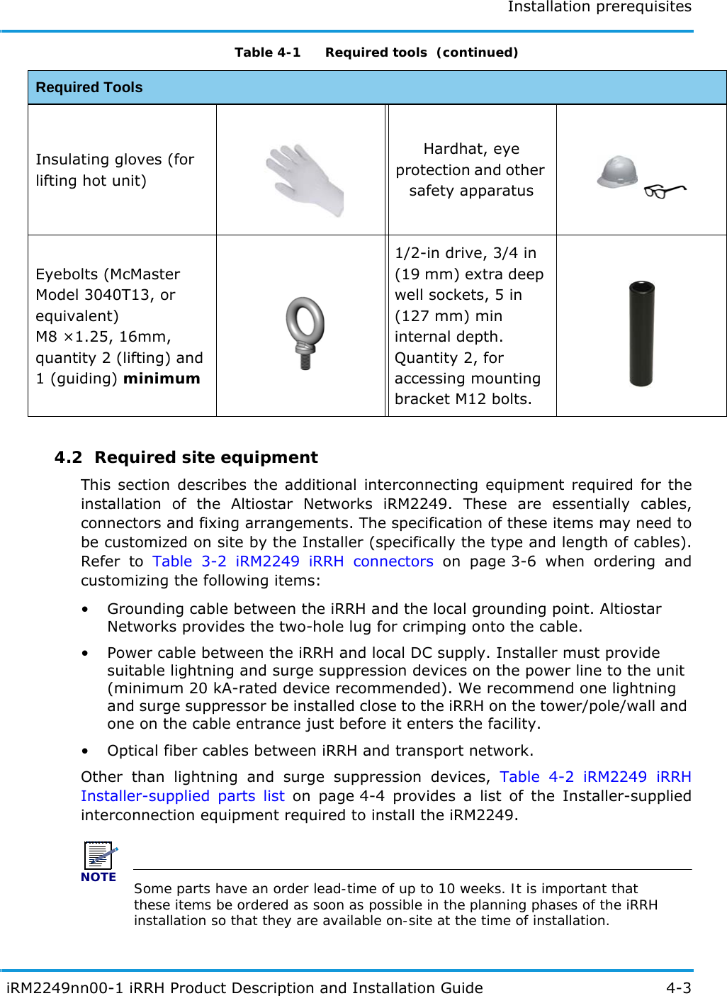
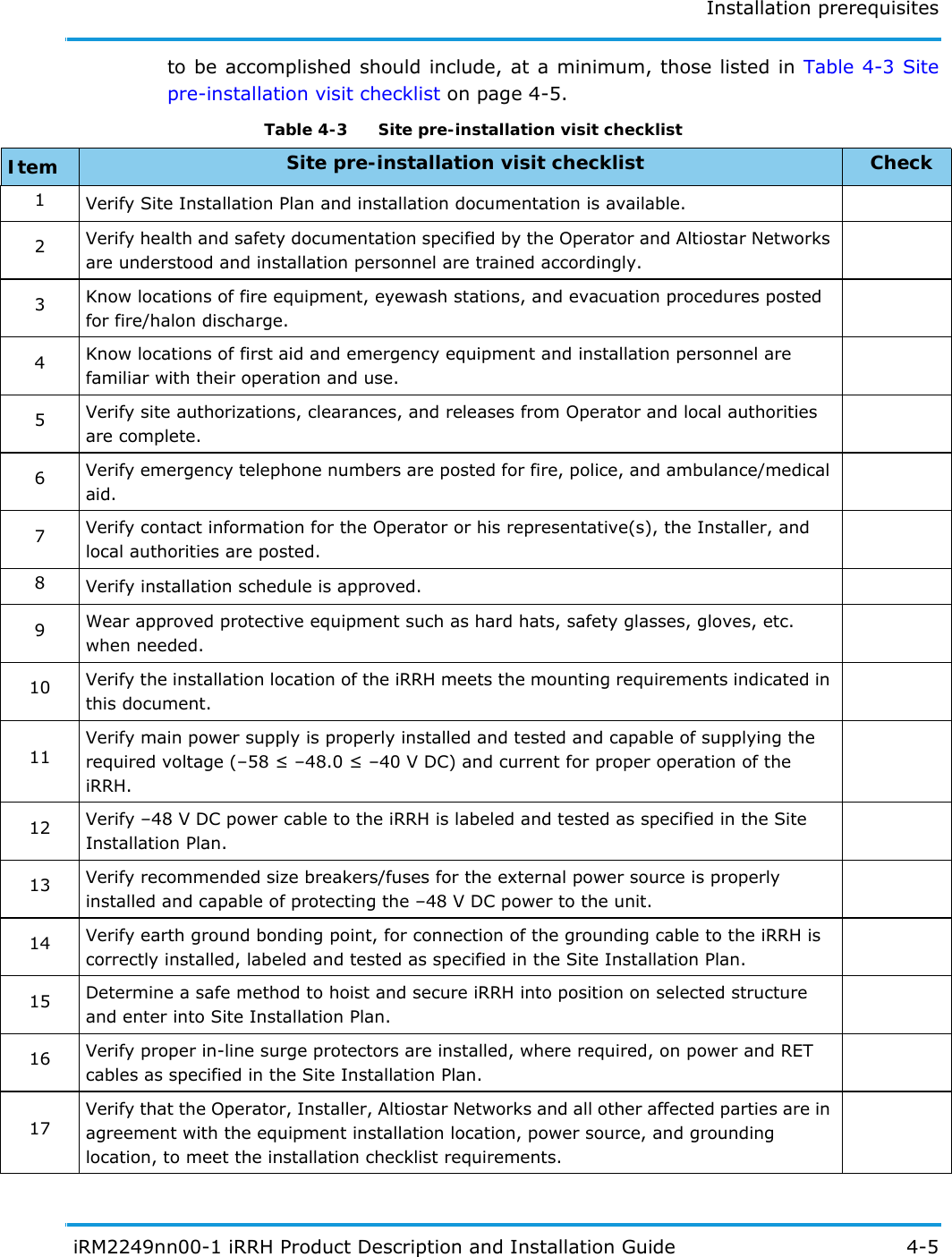
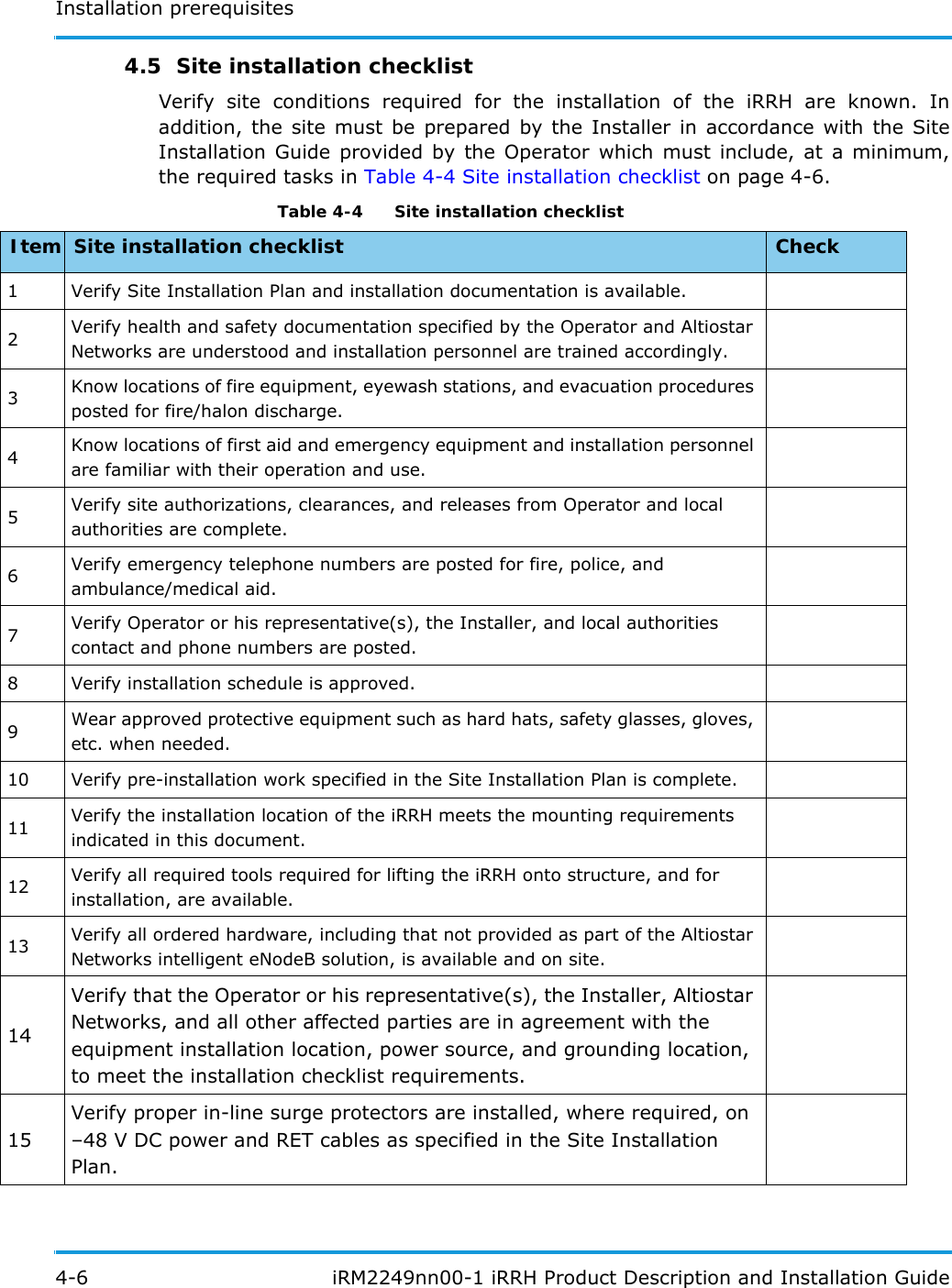
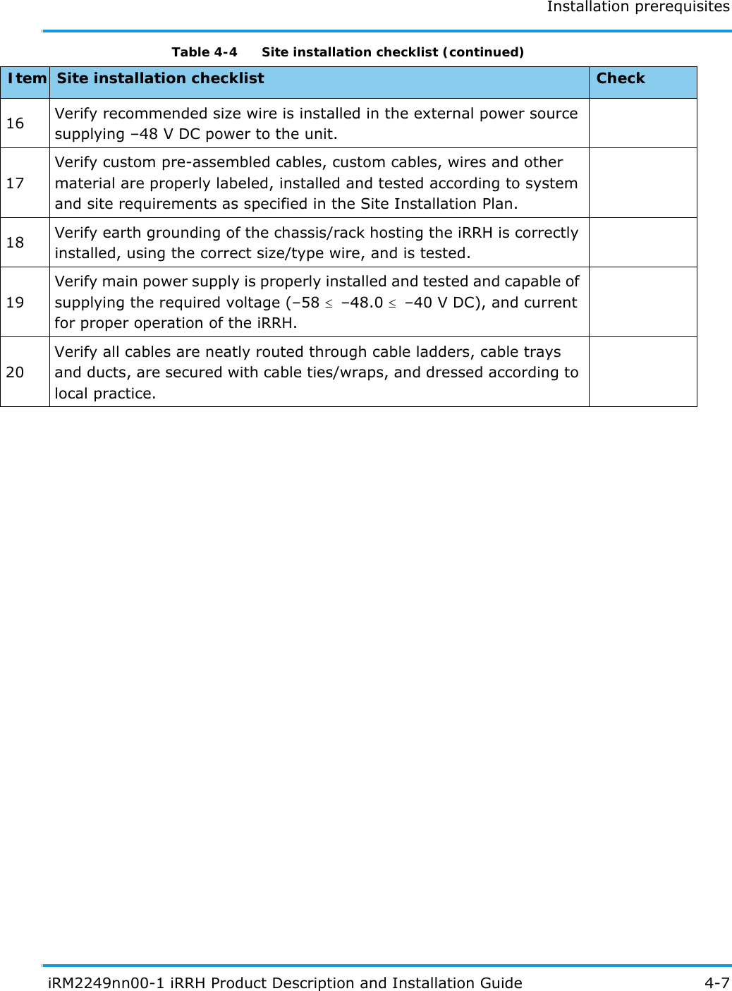
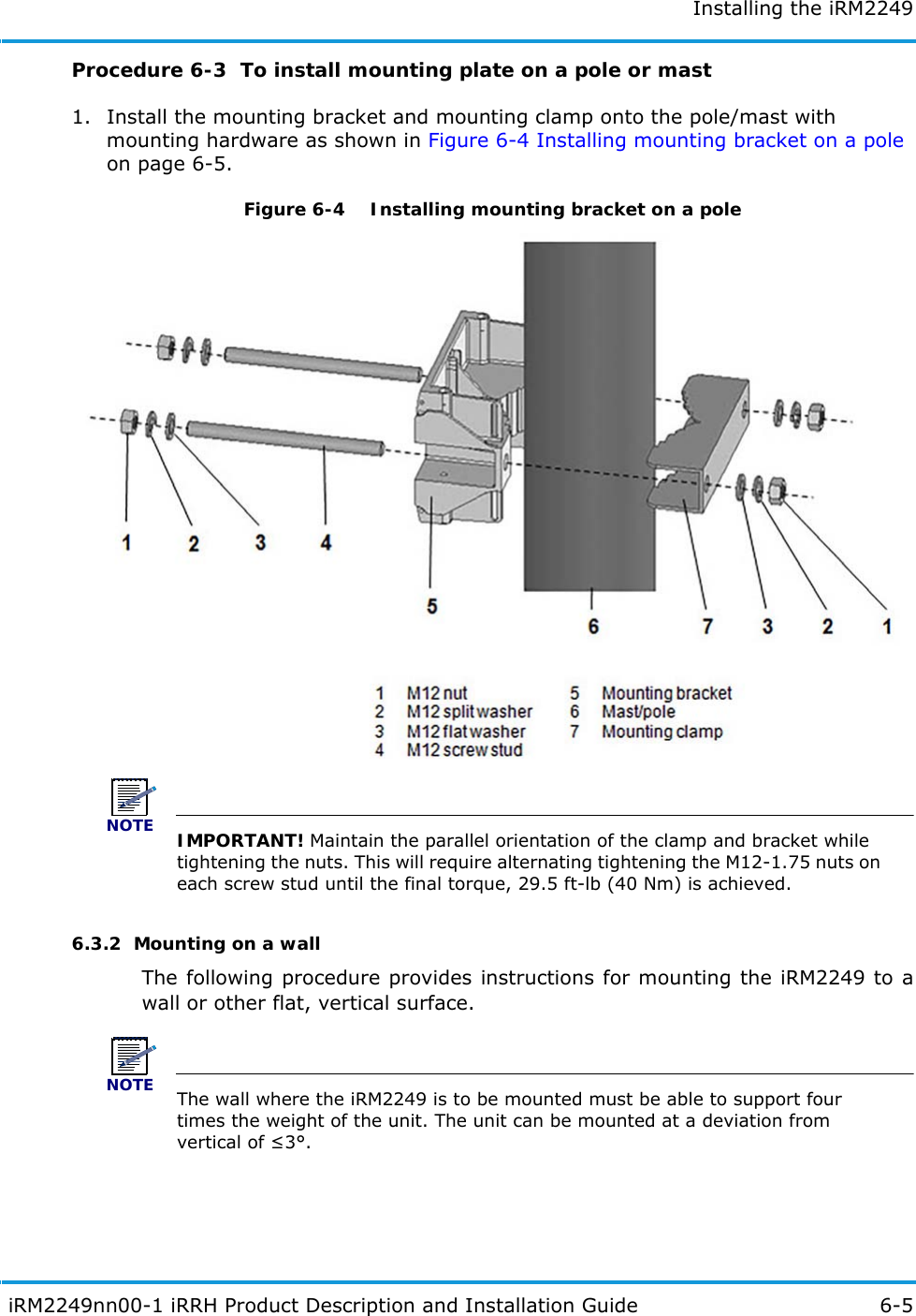
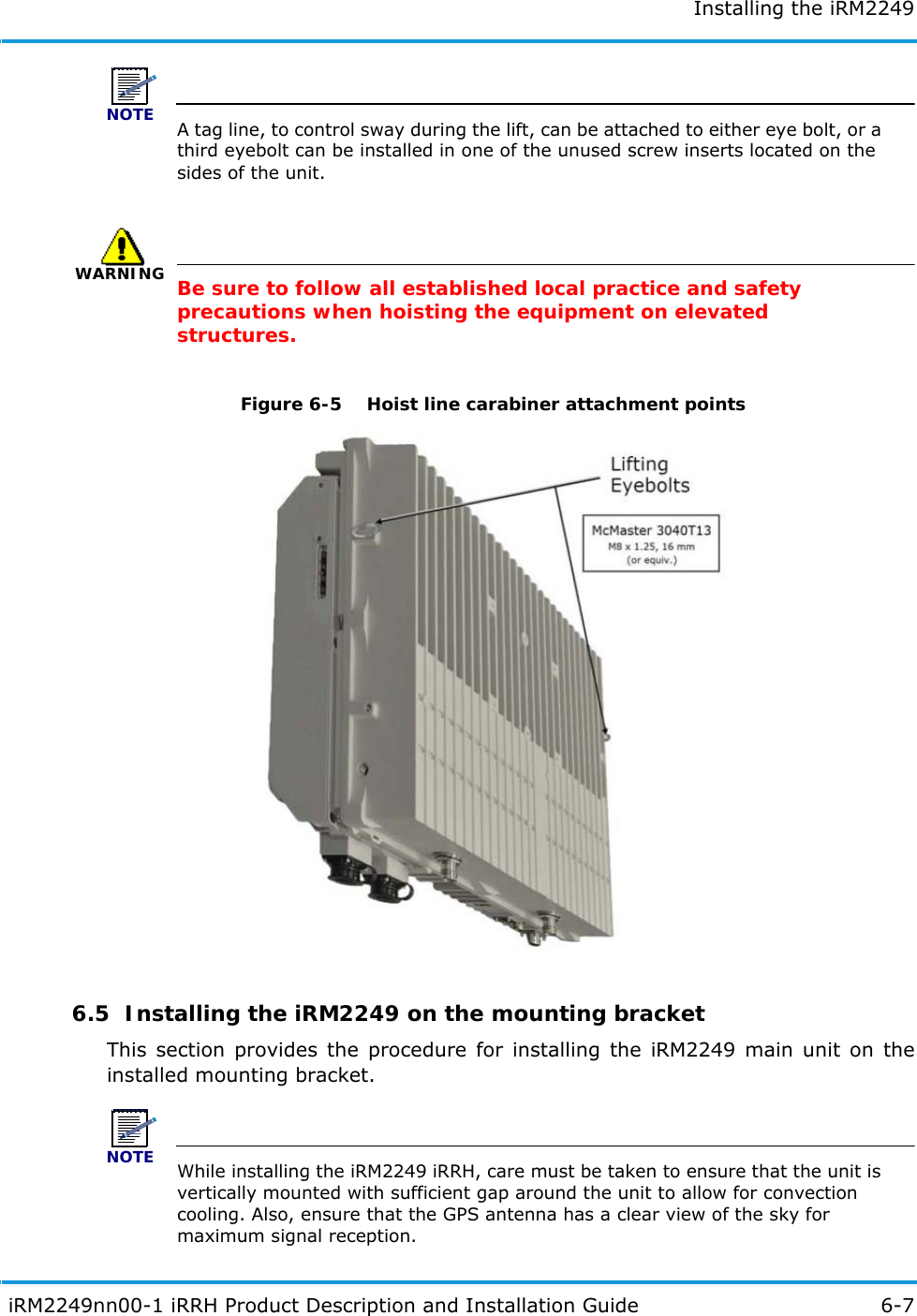
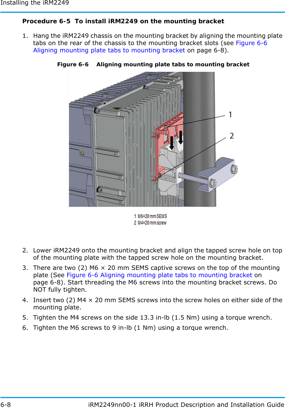
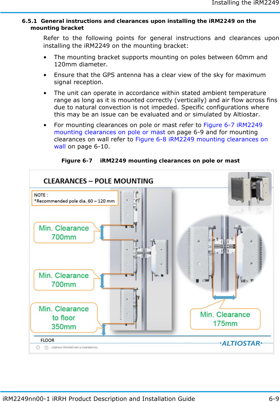
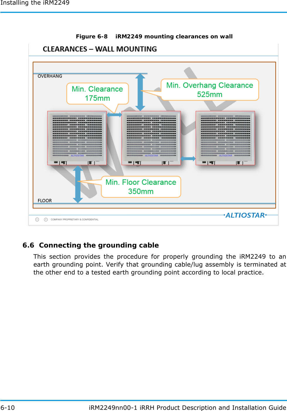
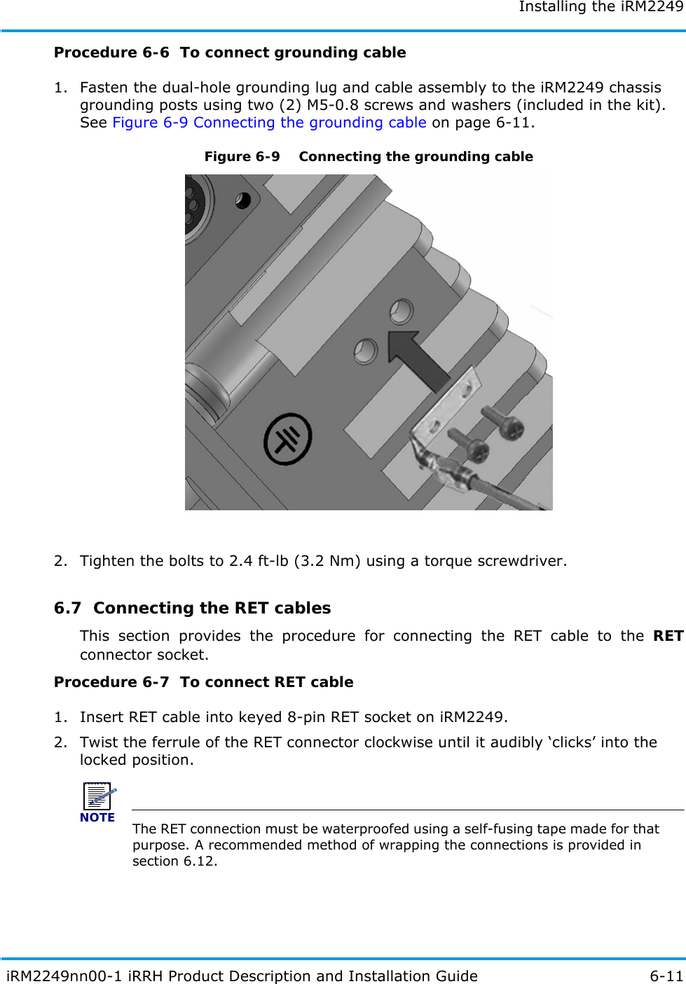
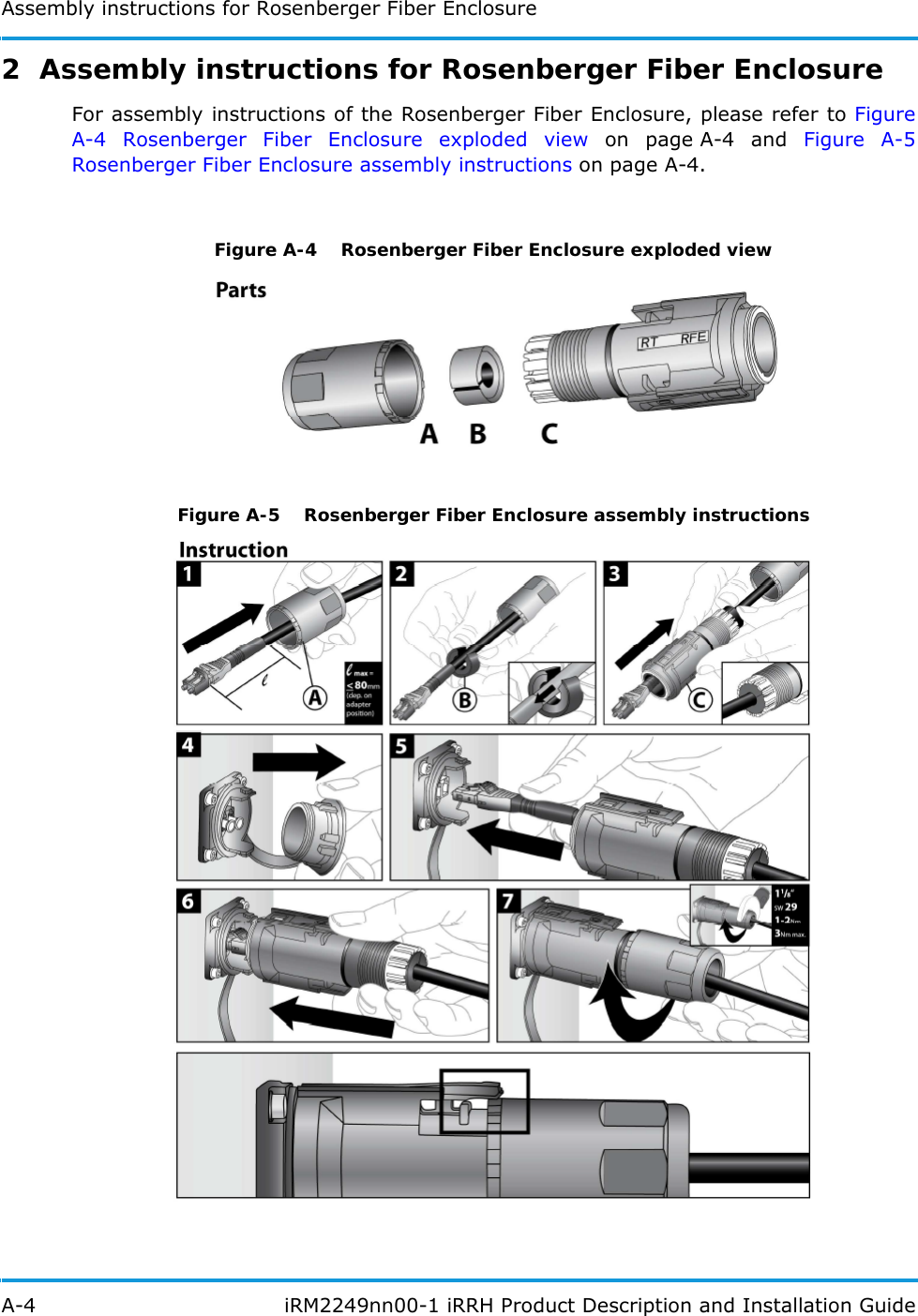
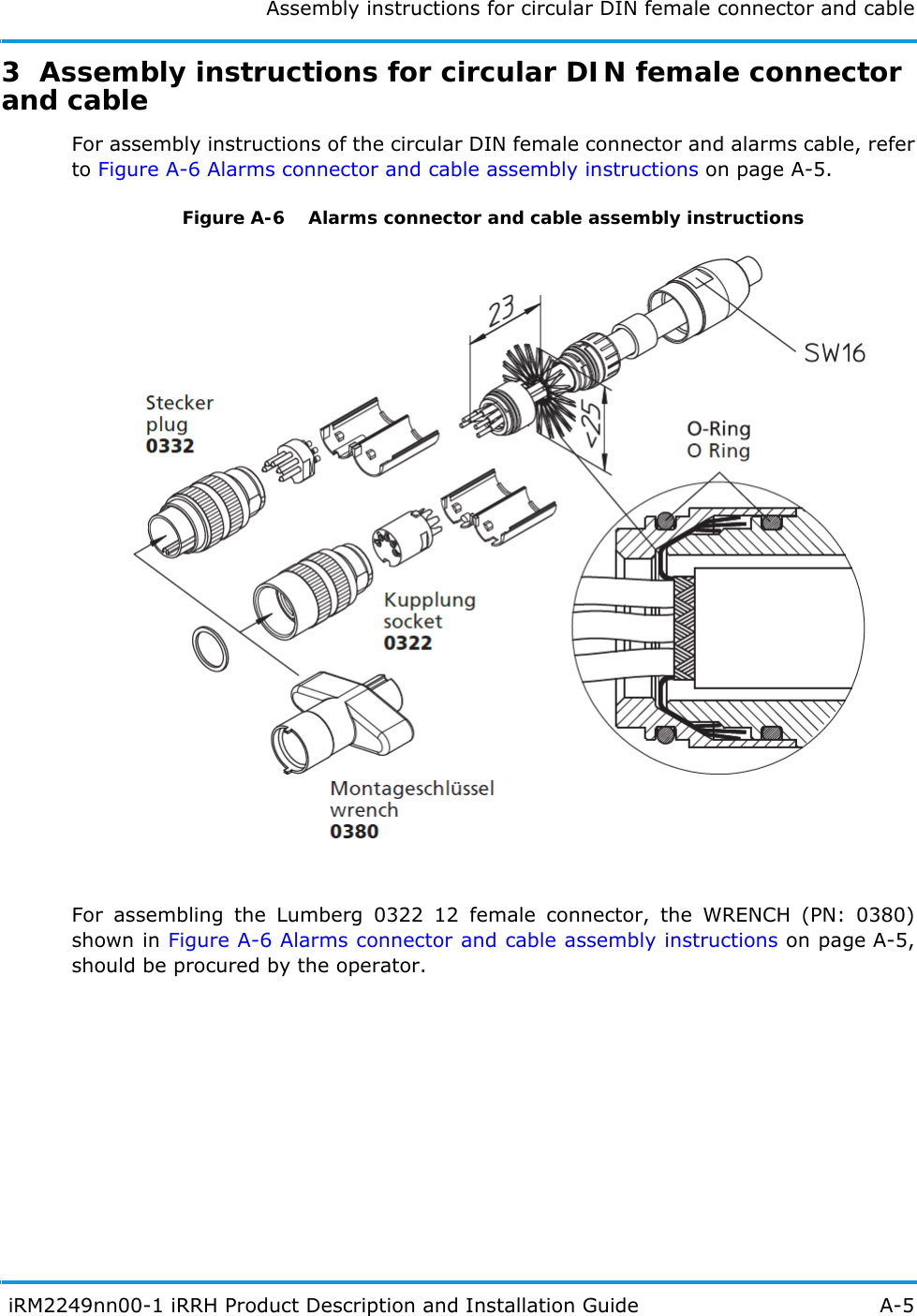
![Installation prerequisites4-4 iRM2249nn00-1 iRRH Product Description and Installation GuideTable 4-2 iRM2249 iRRH Installer-supplied parts list4.3 Site preparationIt is a critical that the conditions in this section must be fulfilled before starting work at the site.4.4 Site pre-installation visit checklistTo verify site conditions required for the installation of the iRRH are known, a pre-installation visit, attended by the Operator's representative, the Installer, Altiostar Networks, and other required parties, must be performed. Tasks required Qty Part Part number Part descriptionInstaller-acquired parts for pre-installation requirements1Splitter/combiner/amp/cableAs specified per site requirementAny splitter/combiner/amp/cable required for shared remote antenna.1Power cableAs specified per site requirementPower cable, 8 AWG min., shielded, round cable. Refer to Power connector on page 3-8 (Installer orders to length according to site requirement.) 1GigE duplexmulti-/singlemodefiberopticcableL-Com (part no.FODLCMIL-nn, orequivalent)GigE duplex multi-/single-modefiber-optic cable, OM1 62.5/125,military fiber cable, with dual LC/dual LC terminations, length sized tosite requirement (model numbershown is for 10 m cable). Foradditional information. Refer to Fronthaul connectors on page 3-12.1AISG RETcontrol cableAs specified per site requirementAISG RET control cable with 8-pin DIN connector in required length. Refer to RET connector on page 3-11.1 per 4 External alarmsAlarm cable As specified per site requirement4-pair, shielded, outdoor-rated, round alarm cable. For additional information, Refer to Alarms connector on page 3-14.3(min)Eyebolt forliftingMcMaster 3040T13T(or equiv)Eyebolt, M8x1.25, 16 mm, SS (third eyebolt to be used for control line [guide] attachment).](https://usermanual.wiki/Altiostar-Networks/22490500/User-Guide-3839650-Page-46.png)