Altiostar Networks 22490500 LTE Band 5 Remote Radio Head User Manual Product Description and Installation Guide
Altiostar Networks, Inc. LTE Band 5 Remote Radio Head Product Description and Installation Guide
Product Description and Installation Guide
PN: 240-00-0057
Issue 1
Altiostar Networks
iRM2249nn00-1
intelligent Remote Radio Head
Product Description and Installation Guide
Copyright © 2018 Altiostar Networks, Inc.
All rights reserved.
iRM2249nn00-1

iRM2249nn00-1 iRRH Product Description and Installation Guide
Copyright © 2018 Altiostar Networks, Inc.
All rights reserved.
DOCUMENT NOTICE: The information contained in this manual is the property of Altiostar and is subject to change
without notice. Altiostar reserves the right to make changes in the design of its products or components as progress
in engineering and manufacturing may warrant. It is the responsibility of the customer to satisfy itself as to whether
the information contained herein is adequate and sufficient for particular use of a user. It is the further responsibility
of each user to ensure that all applications of Altiostar products are appropriate and safe based on conditions
anticipated or encountered during use. This document does not create any additional obligation for Altiostar and
does not constitute additional warranties and representations.
The Altiostar logo is a trademark and a service mark of Altiostar.
Questions: Please call Altiostar General Information at +1-855-709-0701.

Preface
iRM2249nn00-1 iRRH Product Description and Installation Guide P-i
Preface
About the document
This document covers the basic installation of the Altiostar Networks, Inc., iRM2249
intelligent Remote Radio Head (iRRH) on towers, walls, roof or other structures inaccessible
to the general public.
Connections to external interfaces, including signaling, grounding, and power are described.
Descriptions of the iRM2249 macro-cellular intelligent Remote Radio Head indicators are also
provided.
The iRB7200 virtual Baseband Unit (vBBU), the iRB1200 intelligent Baseband Unit and the
iRB2400 intelligent Baseband Unit are companion products. Refer to the Altiostar Networks
iRB1200 intelligent Baseband Unit Product Description and Installation Guide, document
number 240-00-0007, for related information.
Intended Users
The target audience for this document is installation and engineering personnel. It assumes
personnel have a basic understanding of wireless telecommunications terminology, and
experience in installing wireless telecommunications equipment.
Conventions used
Illustrations and photos in this document are intended to show a basic installation. They
show site and equipment configurations encountered during a typical installation. They do
not show all details and exceptions, but highlight the main points of the installation.
Altiostar Networks, Inc. will often be referred to as Altiostar Networks, or simply
Altiostar.
The Altiostar Networks iRM2249 intelligent Remote Radio Head will often be referred to in the
generic as the iRM2249 iRRH, iRM2249, or simply the iRRH.
The Altiostar Networks iRB7200 virtual Baseband Unit (vBBU) is a server-based companion
unit to the iRM2249 in the Altiostar Networks LTE macro eNodeB solution.
The Operator or Owner of the facility and equipment where the iRM2249 iRRH is to be
installed is referred to as the Operator in this document.
The Installer may be the Operator, or any other entity assigned and approved by the
Operator, to perform the installation of the iRRH at specified Operator facilities.

P-ii iRM2249nn00-1 iRRH Product Description and Installation Guide
Preface
NOTE
This is an example of a note used in this document that denotes important
information about the text or procedure that follows it.
iRM2249 available models
Table P-1 iRM2249 iRRH part numbers on page P - ii provides top-level part numbers of
available iRM2249nn00-a models.
Table P-1 iRM2249 iRRH part numbers
Model number Part number Description
iRM22490300-1 509-21-0002 iRM2249, Band 3, 45MHz IBW, 2T2R, 60W, MM SFP
iRM22490500-1 509-26-0001 iRM2249, Band 5, Macro, w/GPS, 20MHz IBW
iRM22490700-1 509-22-0002 iRM2249, Band 7, 45MHz IBW, 2T2R, 60W, MM SFP
iRM22491200-1 509-25-0001 iRM2249, Band 12 Macro, w/GPS, 20MHz IBW
iRM22492000-1 509-20-0001 iRM2249, Band 20, 20MHz IBW, 2T2R, 80W, MM SFP

Contents
iRM2249nn00-1 iRRH Product Description and Installation Guide i
Contents
1 Introduction ........................................................................... 1-1
1.1 Overview..................................................................................... 1-1
1.2 Hardware components .................................................................. 1-2
2 Safety requirements............................................................... 2-1
2.1 Overview..................................................................................... 2-1
2.2 Purpose ...................................................................................... 2-1
2.3 Warning symbols.......................................................................... 2-1
2.4 General safety precautions ............................................................ 2-1
3 Physical description................................................................ 3-1
3.1 iRM2249 iRRH boards and modules ................................................. 3-3
3.2 iRM2249 iRRH controls, indicators connectors and components........... 3-3
3.2.1 Grounding terminal lug.......................................................... 3-6
3.2.2 GPS connector...................................................................... 3-7
3.2.3 RF connectors ...................................................................... 3-8
3.2.4 Power connector................................................................... 3-8
3.2.5 RET connector.................................................................... 3-11
3.2.6 Fronthaul connectors........................................................... 3-12
3.2.7 Alarms connector................................................................ 3-14
3.2.8 Access panel (factory use only) ............................................ 3-15
3.2.9 LED indicators .................................................................... 3-16
3.2.10 Vent port ......................................................................... 3-18
4 Installation prerequisites ....................................................... 4-1
4.1 Required tools.............................................................................. 4-1
4.2 Required site equipment................................................................ 4-3
4.3 Site preparation ........................................................................... 4-4
4.4 Site pre-installation visit checklist................................................... 4-4
4.5 Site installation checklist ............................................................... 4-6
5 Installation overview.............................................................. 5-1
5.1 Installation procedures.................................................................. 5-1
5.2 Unpacking the shipping container ................................................... 5-1
5.3 Verifying all parts received............................................................. 5-2
6 Installing the iRM2249 ........................................................... 6-1
6.1 Assembling cables ........................................................................ 6-1
6.1.1 Verify Installer-supplied –48 V DC power cable ......................... 6-1
6.1.2 Verify Installer-supplied GigE optical cable ............................... 6-1
6.1.3 Verify Installer-supplied grounding cable.................................. 6-2
6.2 Routing pre-assembled power/GigE optical fronthaul/grounding
cables......................................................................................... 6-3
6.3 Installing the mounting bracket ...................................................... 6-4
6.3.1 Mounting on a pole/mast ....................................................... 6-4
6.3.2 Mounting on a wall................................................................ 6-5

Contents
ii iRM2249nn00-1 iRRH Product Description and Installation Guide
6.4 Hoisting the iRM2249 on elevated structures .................................... 6-6
6.5 Installing the iRM2249 on the mounting bracket ............................... 6-7
6.5.1 General instructions and clearances upon installing the
iRM2249 on the mounting bracket ........................................... 6-9
6.6 Connecting the grounding cable.................................................... 6-10
6.7 Connecting the RET cables........................................................... 6-11
6.8 Connecting the GigE optical fronthaul cables .................................. 6-12
6.9 Connecting the RF cables............................................................. 6-12
6.10 Connecting the alarms cable ...................................................... 6-13
6.11 Connecting the –48 V DC power cable ......................................... 6-13
6.12 Weatherproofing cable connections ............................................. 6-14
6.13 Checking power........................................................................ 6-15
7 Terms, Acronyms and Abbreviations...................................... 7-1
Appendix A Assembly instructions ........................................A-1
1 Assembly instructions for 2-pin power connector and cable... A-1
2 Assembly instructions for Rosenberger Fiber Enclosure ......... A-4
3 Assembly instructions for circular DIN female connector
and cable ................................................................................ A-5

List of figures
iRM2249nn00-1 iRRH Product Description and Installation Guide iii
List of figures
Figure 1-1 iRM2249 iRRH functional block diagram .................................... 1-2
Figure 3-1 Altiostar Networks iRM2249 iRRH.............................................. 3-1
Figure 3-2 iRM2249 iRRH RF connectors location ........................................ 3-4
Figure 3-3 iRM2249 iRRH RET and –48VDC (power) connector location ......... 3-4
Figure 3-4 iRM2249 iRRH GPS and fronthaul connectors location .................. 3-5
Figure 3-5 iRM2249 iRRH ground connector location ................................... 3-5
Figure 3-6 Grounding terminal lug details.................................................. 3-7
Figure 3-7 –48 V DC 2-pin Rosenberger bulkhead jack................................ 3-8
Figure 3-8 Rosenberger –48 V DC power plug (exploded view)..................... 3-9
Figure 3-9 Cable connection for supplied 2-pin Rosenberger plug ............... 3-10
Figure 3-10 RET standard 8-pin DIN connector ........................................ 3-11
Figure 3-11 Rosenberger RFE fiber-optic enclosure ................................... 3-13
Figure 3-12 Lumberg 0322 12 connector and pin assignment..................... 3-14
Figure 3-13 Lumberg 0322 12 connector exploded view ............................ 3-14
Figure 3-14 iRM2249 SPM module, Test Access Panel and LED panel........... 3-16
Figure 3-15 Vent port ........................................................................... 3-19
Figure 6-1 Grounding terminal lug assembled on grounding cable................. 6-2
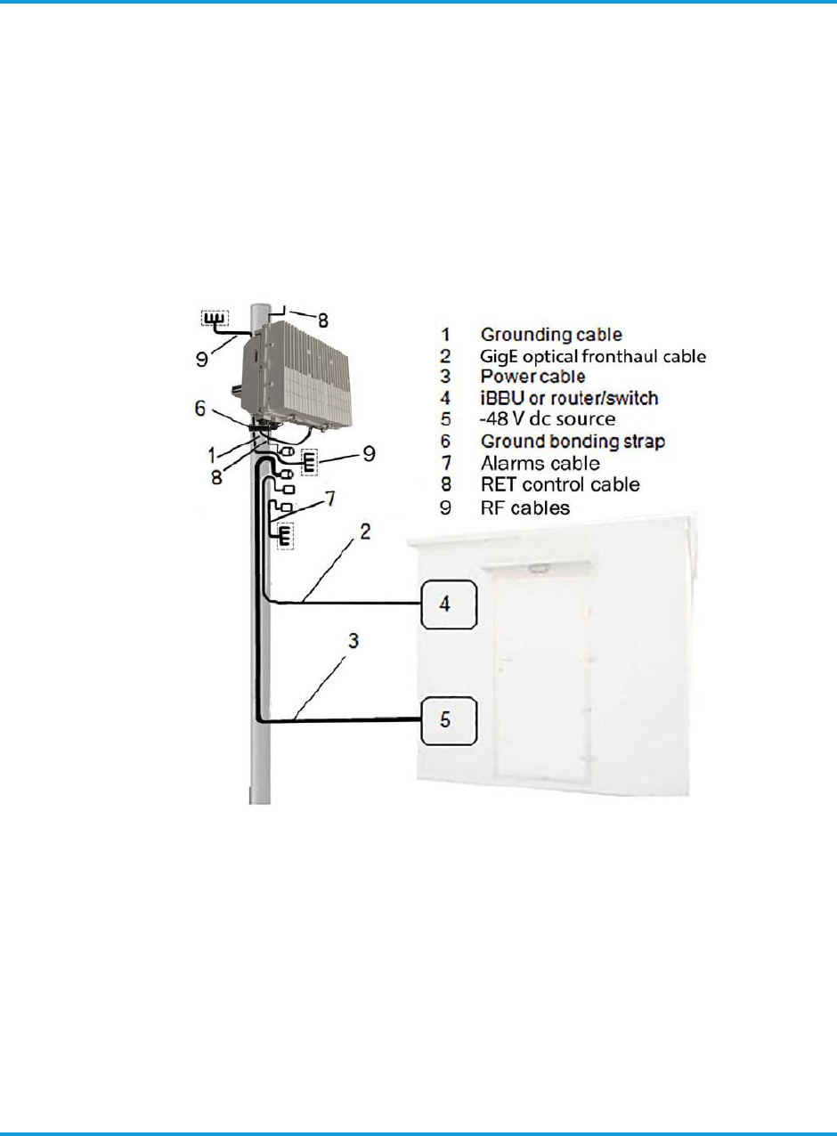
Figure 6-2 iRM2249 cable routing............................................................. 6-3
Figure 6-3 iRM2249mounting plate........................................................... 6-4
Figure 6-4 Installing mounting bracket on a pole........................................ 6-5
Figure 6-5 Hoist line carabiner attachment points....................................... 6-7
Figure 6-6 Aligning mounting plate tabs to mounting bracket....................... 6-8
Figure 6-7 iRM2249 mounting clearances on pole or mast ........................... 6-9
Figure 6-8 iRM2249 mounting clearances on wall ..................................... 6-10
Figure 6-9 Connecting the grounding cable.............................................. 6-11
Figure 6-10 Weatherproofing connections using self-fusing tape................. 6-14
Figure A-1 Rosenberger 2-pin power connector and cable............................ A-1
Figure A-2 Preparing the cable................................................................. A-2
Figure A-3 Connecting the cable with the connector.................................... A-3
Figure A-4 Rosenberger Fiber Enclosure exploded view ............................... A-4
Figure A-5 Rosenberger Fiber Enclosure assembly instructions ..................... A-4
Figure A-6 Alarms connector and cable assembly instructions ...................... A-5

List of figures
iv iRM2249nn00-1 iRRH Product Description and Installation Guide

List of tables
iRM2249nn00-1 iRRH Product Description and Installation Guide v
List of tables
Table P-1 iRM2249 iRRH part numbers........................................................P-ii
Table 3-1 Altiostar Networks iRM2249 iRRH technical specifications ............... 3-2
Table 3-2 iRM2249 iRRH connectors .......................................................... 3-6
Table 3-3 Lumberg 0315 12 alarm connector details.................................. 3-15
Table 3-4 LED indicators description and operating characteristics ............... 3-17
Table 3-5 LED blink rates ....................................................................... 3-17
Table 3-6 LED indicators boot-up sequence .............................................. 3-18
Table 4-1 Required tools .......................................................................... 4-1
Table 4-2 iRM2249 iRRH Installer-supplied parts list .................................... 4-4
Table 4-3 Site pre-installation visit checklist ............................................... 4-5
Table 4-4 Site installation checklist............................................................ 4-6
Table 5-1 iRM2249 iRRH parts list ............................................................. 5-2

List of tables
vi iRM2249nn00-1 iRRH Product Description and Installation Guide

List of procedures
iRM2249nn00-1 iRRH Product Description and Installation Guide vii
List of procedures
Procedure 5-1 To unpack the shipping container ........................................ 5-2
Procedure 6-1 To install ground terminal lug.............................................. 6-2
Procedure 6-2 To route cables ................................................................. 6-3
Procedure 6-3 To install mounting plate on a pole or mast........................... 6-5
Procedure 6-4 To install mounting plate on a wall....................................... 6-6
Procedure 6-5 To install iRM2249 on the mounting bracket.......................... 6-8
Procedure 6-6 To connect grounding cable .............................................. 6-11
Procedure 6-7 To connect RET cable....................................................... 6-11
Procedure 6-8 To connect GigE optical fronthaul cables ............................. 6-12
Procedure 6-9 To connect the RF cables.................................................. 6-12
Procedure 6-10 To connect the alarms cable............................................ 6-13
Procedure 6-11 To connect the DC power cable........................................ 6-13
Procedure 6-12 To weatherproof cable connections .................................. 6-14
Procedure 6-13 To check power to the macro iRRU................................... 6-15

List of procedures
viii iRM2249nn00-1 iRRH Product Description and Installation Guide

Introduction
iRM2249nn00-1 iRRH Product Description and Installation Guide 1-1
1 Introduction
1.1 Overview
The iRM2249 intelligent Remote Radio Head is an energy-efficient outdoor
macrocell radio head with integrated baseband for use in several select frequency
bands. Connection to a vBBU, or the optional iRB1200 iBBU or iRB2400 iBBU, is
through a Gigabit Ethernet (GigE) connection. Connection to other compliant
fronthaul devices can also be facilitated using the Ethernet fronthaul port.
The iRM2249 intelligent Remote Radio Head is based on a distributed architecture
with the following two essential elements:
• iRM2249 iRRH
• iRB7200 vBBU, iRB1200 iBBU, or iRB2400 iBBU
The iRM2249 iRRH is connected to the vBBU through a Gigabit Ethernet (GigE)
connection. Connection to other compliant fronthaul devices can also be facilitated
using the Ethernet fronthaul port.
The iRM2249 iRRH interconnects with the described Altiostar baseband units which
operate within the RAN portion of the LTE wireless network.
The iRM2249 interconnects with compliant radio antennas and the associated
baseband unit, i.e., vBBU (or the optional iRB1200/iRB2400 iBBUs) which operate
within the RAN portion of the LTE wireless network.
Introduction
1-2 iRM2249nn00-1 iRRH Product Description and Installation Guide
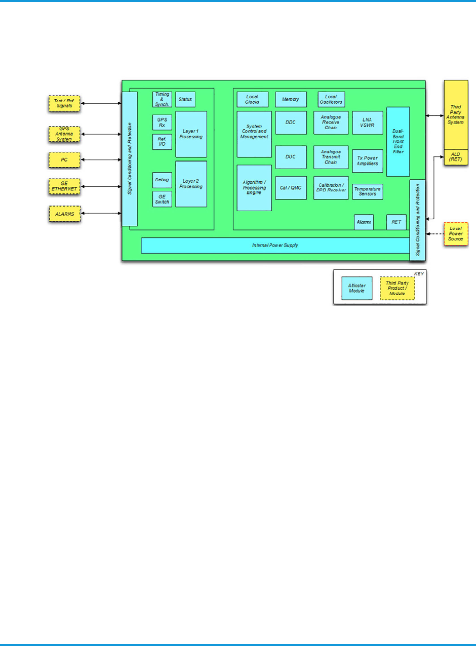
A block diagram of the iRM2249 iRRH is shown in Figure 1-1 iRM2249 iRRH
functional block diagram on page 1 - 2.
Figure 1-1 iRM2249 iRRH functional block diagram
1.2 Hardware components
The following major circuit cards and components comprise the iRM2249 iRRH.
See Figure 1-1 iRM2249 iRRH functional block diagram on page 1 - 2.
• Signal Processing Module
•Radio Card
• Signal Conditioning and Protection
• Internal power supply
• Front-end Filter
• Fronthaul Interface
• GPS Receiver System
• RF Antenna System
•Local Power Source
• Alarms Interface
The iRM2249 gets its power from an external –48 V DC source. Antennas, supplied
by the Operator, are used for RF transmission and Global Positioning System
(GPS) reception.

Introduction
iRM2249nn00-1 iRRH Product Description and Installation Guide 1-3
The Signal Processing Module (SPM) provides single-carrier, dual-carrier, multi
band, single sector LTE eNodeB operation; it is the Gigabit interface to the
Altiostar base station unit (vBBU). It also provides for 20 MHz (max) and 45 MHz
(max) instantaneous carrier bandwidth (IBW) support for 3GPP LTE Release 11
advanced features, L1/L2 signal conditioning, signal protection and signal
processing of the fronthaul signal inputs, as well as eNodeB timing recovery and
synchronization from either the external GPS antenna or 1588V2 extraction of
timing from the Layer 2 stratum. It supports test and reference signal I/O for
radio conformance testing (RCT), and Data and Control interface to the radio card.
An external alarms input is located on the bottom of the iRM2249 unit. There are
four sets of 2-wire dry contacts that can be software-configured to be normally
open or normally closed.

Introduction
1-4 iRM2249nn00-1 iRRH Product Description and Installation Guide
Safety requirements
iRM2249nn00-1 iRRH Product Description and Installation Guide 2-1
2 Safety requirements
2.1 Overview
This section provides safety precautions that apply to the iRM2249 iRRH. The
precautions statements are required by national or regional standards institutes in
the country or region where they apply. This document complies with these
requirements.
2.2 Purpose
To protect installation personnel, equipment and operations, this document
contains safety statements. Safety statements are provided at points in
procedures where risks may exist to personnel, equipment and network
operations. Failure to follow the directions in the safety statements may result in
serious consequences.
2.3 Warning symbols
DANGER
Danger is used to indicate the presence of a hazard that will cause
severe personal injury, death, or substantial property damage if the
hazard is not avoided.
WARNING
Warning is used to indicate the presence of a hazard that can cause
severe personal injury, death, or substantial property damage if the
hazard is not avoided.
CAUTION
Caution is used to indicate the presence of a hazard that will or can
cause minor personal injury or property damage if the hazard is not
avoided.
2.4 General safety precautions
Safety precautions should be observed when performing these installation
procedures.
NOTE
The safety precautions found in this section are only intended to supplement
those safety precautions already proscribed by the Operator—who is responsible
for communicating them clearly to the Installer.
Safety requirements
2-2 iRM2249nn00-1 iRRH Product Description and Installation Guide
The power system and RET cables will have hazardous energy and voltages
present. Follow all safety warnings and practices when servicing this equipment.
This equipment must be installed, serviced, and operated only by authorized,
qualified and trained personnel who have the necessary knowledge and practical
experience with electrical equipment and who understand the hazards that can
arise when working on this type of equipment. Observe all local and national
electrical, environmental and workplace codes.
DANGER
HAZARDOUS VOLTAGES!
Hazardous voltages can be present when the system is operating. Use
caution when removing or installing equipment.
DANGER
FALL HAZARD!
A fall hazard is present when installation of this equipment requires
working on towers, poles or at elevated work sites. All telecommunications
personnel who perform tower work or work at elevation must be qualified
to perform this type work.
Installation of this equipment may require working on towers, poles or at
elevated work sites. All telecommunications personnel who perform tower
work or work at elevation must be trained and qualified to perform this
work, have the proper equipment to perform the work safely, and follow all
requirements in accordance with 29 CFR 1910.268, 29 CFR 1926, and any
other safety requirements in force by the Operator, or local and regional
authorities. In addition, the tower or structure must be certified safe for
climbing according to TIA/EIA 222 and 29 CFR 1910.66, Appendix C for
anchorage devices.
WARNING
Read and understand all instructions before starting this procedure!
•Follow all warnings and safety instructions in this procedure.
• Only trained personnel should install or operate this equipment.
• Observe all local and national electrical, environmental and workplace
codes.
• Before working on equipment that is connected to power, remove
jewelry (including rings, necklaces, and watches). Metal objects will
heat up when connected to power and ground and can cause serious
burns or weld the metal object to the terminals.
• The equipment must have a direct disconnect device in line with the
power source.

Safety requirements
iRM2249nn00-1 iRRH Product Description and Installation Guide 2-3
• Grounding and circuit integrity is vital to a safe operating environment.
Grounding conductors must be in place before installing the equipment.
Never operate equipment when grounding or bonding conductor has
been removed.
• Never install equipment not identified in this procedure. Fire or injury
could result from improperly installed equipment.
• Caution should be exercised when installing or modifying
telecommunications lines.
• Disconnect all power sources before servicing the equipment.
• Never touch uninsulated wiring or terminals unless power to the lines
have been disconnected at the source. Always verify power has been
removed using an approved voltage tester.
• To prevent electrical shock, never remove the cover or disassemble the
equipment. There are no user serviceable components in the
equipment.
• Never insert probes or objects of any kind into slots or openings to the
equipment. Dangerous voltages may be present or the object may
cause a short circuit and start a fire or damage the equipment.
CAUTION
HOT SURFACES!
• Under certain conditions, specifically during and immediately after
prolonged operation, the unit can be hot. Wait for unit to cool before
performing maintenance or use insulating gloves.
CAUTION
HEAVY OBJECT!
• Assisted carry ONLY! This object is heavy; over 75 lb. (34.0 kg). Follow
instructions when lifting unit from shipping container and hoisting onto
mounting bracket. Requires a minimum of two people to lift and hand
carry the unit.
Safety requirements
2-4 iRM2249nn00-1 iRRH Product Description and Installation Guide
WARNING
LIGHTNING STRIKE HAZARD!
• Lightning strikes are possible during stormy weather. Do not install
equipment if stormy conditions exist.
• Never work on telecommunications power supply lines or antenna
feeders at the cell site during stormy conditions.
WARNING
SHOCK HAZARD!
• Some parts of all electrical systems are energized at all times. Exercise
extreme caution at all times when working around telecommunications
electrical systems. Short circuits can cause burns to the face or hands.
Failure to observe this and other safety warnings may lead to bodily
injury and property damage.
• Only trained and qualified personnel may install or service equipment
as defined in IEC 215 and EN 60215.
• Turn off or disconnect equipment from its energy source(s) by
switching off the load disconnect switch in the distribution panel before
performing service or maintenance.
CAUTION
LASER RADIATION AND FIBER OPTIC CABLE USE CAUTION!
• Class 1 invisible laser radiation present. Avoid long-term viewing of
laser. Never use a magnifying device to view optical fiber ends when
fiber is connected to equipment.
• Fiber optic cables may be damaged if bent or curved to a radius that is
less than the recommended minimum bend radius of two inches.
Always observe the recommended bend radius limit when installing
fiber optic cables and patch cords.
CAUTION
SHORT CIRCUIT HAZARD!
Condensation on the equipment has a potential to cause short circuits!
Weather conditions may exist at the site where condensation may form on
the equipment. Installing or operating the equipment when condensation is
present may cause a short circuit and damage the equipment.
Safety requirements
iRM2249nn00-1 iRRH Product Description and Installation Guide 2-5
Equipment showing signs of condensation should be allowed to dry before
installation.
CAUTION
ELECTROSTATICALLY SENSITIVE EQUIPMENT!
Semiconductor components are sensitive to electrostatic electricity and
may be damaged by static discharge.
When handling the equipment, the following rules must be followed:
• Wear conductive or anti-static clothing.
• Wear grounded ESD wrist strap.
• Wear shoes with conductive straps or soles.
• Verify anti-static safety devices are operating properly by testing
yourself at an approved test station.
• Leave equipment in their original anti-static wrapping until ready for
installation.
• When handling equipment or modules, use handles provided to carry
the device and do not touch electrical contacts, pins or components.
• Only place equipment or modules on conductive surfaces.
• Use tools on equipment or modules only when equipment is grounded.
• Handle defective equipment or modules similarly to new equipment to
prevent additional damage.
CAUTION
GROUNDING CAUTION!
• This equipment's grounding connection is between the DC power circuit
and the grounding conductor.
• This equipment must have a direct connection to the DC supply
grounding point or to a bonding jumper from the grounding terminal
bus bar to the DC supply ground electrode for the site.
• The grounding circuit must not have a disconnect device located in line
with the DC circuit grounding conductor.

Safety requirements
2-6 iRM2249nn00-1 iRRH Product Description and Installation Guide
Physical description
iRM2249nn00-1 iRRH Product Description and Installation Guide 3-1
3 Physical description
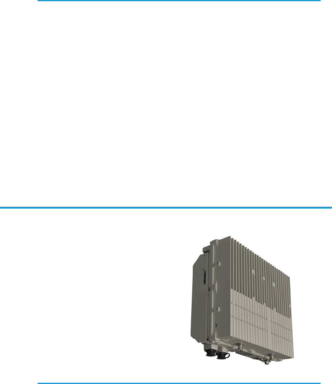
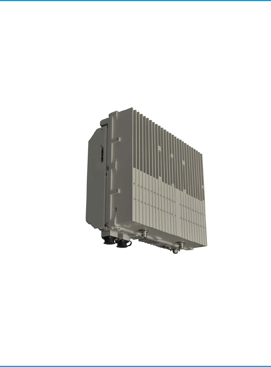
The Altiostar Networks iRM2249 intelligent Remote Radio Head is an energy-efficient,
modular, outdoor radio unit constructed of aluminum with integrated heat sink fins to
facilitate fanless convection cooling. There are two independent RF outputs for a 2T2R
configuration at 30 W or 40 W per RF path for a total of 60 W or 80 W maximum
output power.
The iRM2249 iRRH has connections for –48 V DC power input and Gigabit Ethernet
optical fronthaul.
Figure 3-1 Altiostar Networks iRM2249 iRRH on page 3-1 shows the iRM2249 iRRH.
Figure 3-1 Altiostar Networks iRM2249 iRRH
The Altiostar Networks iRM2249 iRRH can be mounted on a wall, mast or tower using
the supplied mounting bracket assembly and mounting plate. Table 3-1 Altiostar
Networks iRM2249 iRRH technical specifications on page 3-2 lists the specifications of
the iRM2249 iRRH by characteristic type. The Installer is responsible for supplying and
installing antennas and associated cables for the GPS and RF signals. For
recommendations on the antenna type, the RET motor, and the RET cable assembly
contact Altiostar Networks engineering prior to the site pre-installation visit.

Physical description
3-2 iRM2249nn00-1 iRRH Product Description and Installation Guide
.
Table 3-1 Altiostar Networks iRM2249 iRRH technical specifications
Item Specification
Physical
Dimensions (H×W×D)
Radio Module
SPM
Radio+SPM
15.4 × 19.1 × 6.2 in (392 × 485 × 158 mm)
13.8 × 6.4 × 0.9 in (350 × 164 × 24 mm)
15.4× 19.1 × 7.2in (392 × 485× 182mm)
Weight
- Excludes brackets 61.7 lb (28.0 kg)
Volume 32.8 L
Electrical
Input power -48 VDC (-58 -48 -40 VDC)
Typical power consumption <350W
Maximum power consumption <400W
BTU output – Typical BTU/hr 945 BTU/hr
BTU output – Maximum BTU/hr 1055 BTU/hr
TRx Configuration 2T2R
Normal RF output power • 80W (2 x 40W) for Aldebaran low band
• 60W (2 x 30W) for Aldebaran high band
Typical current drawn ~ 7A at -48VDC
Maximum current drawn ~ 10A at -40VDC
Power distribution breaker/fuse
15A
(At -40 VDC, maximum current is 10A. Per NEC guidelines,
breaker should be sized for 125% of continuous load and 100%
of non-continuous load. For this class of device as a primarily
resistive load, circuit breaker should be a minimum of 15A.)
NOTE:
• Typical conditions include 25 Deg C, 90% Data loading, and power input of -48VDC.
• Maximum conditions include 55 Deg C, +1dB over the rated power, and power input of -40VDC.
• Normal conditions include 25 Deg C, 100% Data loading, and power input of -48VDC.
• The specifications mentioned above are applicable for Aldebaran low band (unless otherwise
specified) only. Upon completing the testing, the above specifications will be updated for
Aldebaran high band.

Physical description
iRM2249nn00-1 iRRH Product Description and Installation Guide 3-3
3.1 iRM2249 iRRH boards and modules
The iRM2249 intelligent Remote Radio Head is an integral unit with no user-
accessible boards or modules.
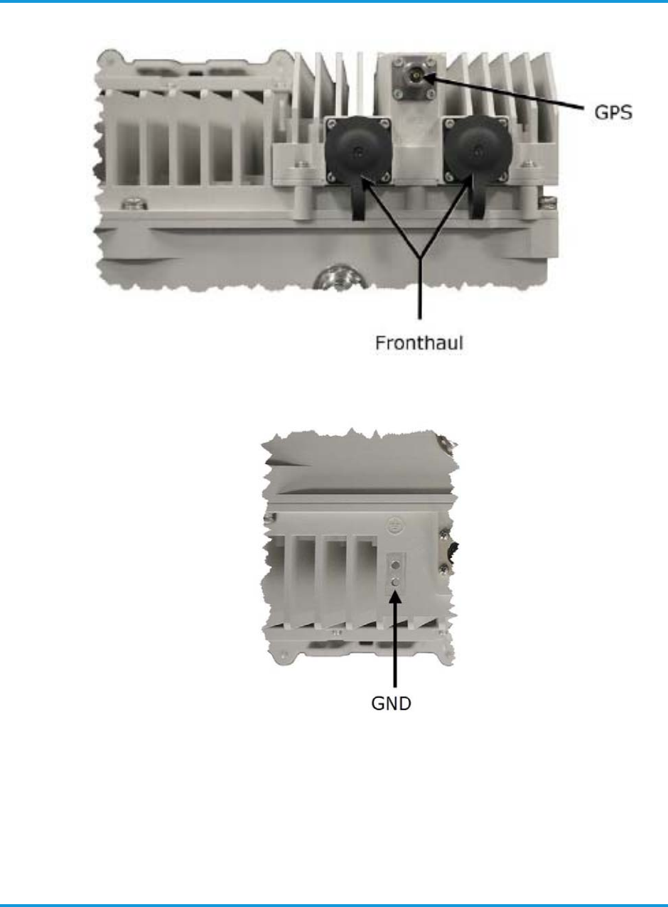
3.2 iRM2249 iRRH controls, indicators connectors and components
There are no controls on the macro iRRH. The connectors are located on the
bottom of the unit. They are for Global Positioning System antenna (GPS), Power
(–48v DC), RF (ANT1–ANT2), alarm connector, Fronthaul (FH1/FH2), Ground
(), and Remote Electrical Tilt (RET).
LEDs for Fronthaul 1 (FH1), Fronthaul 2 (FH2), STATUS, and POWER are
located on the bottom of the unit.
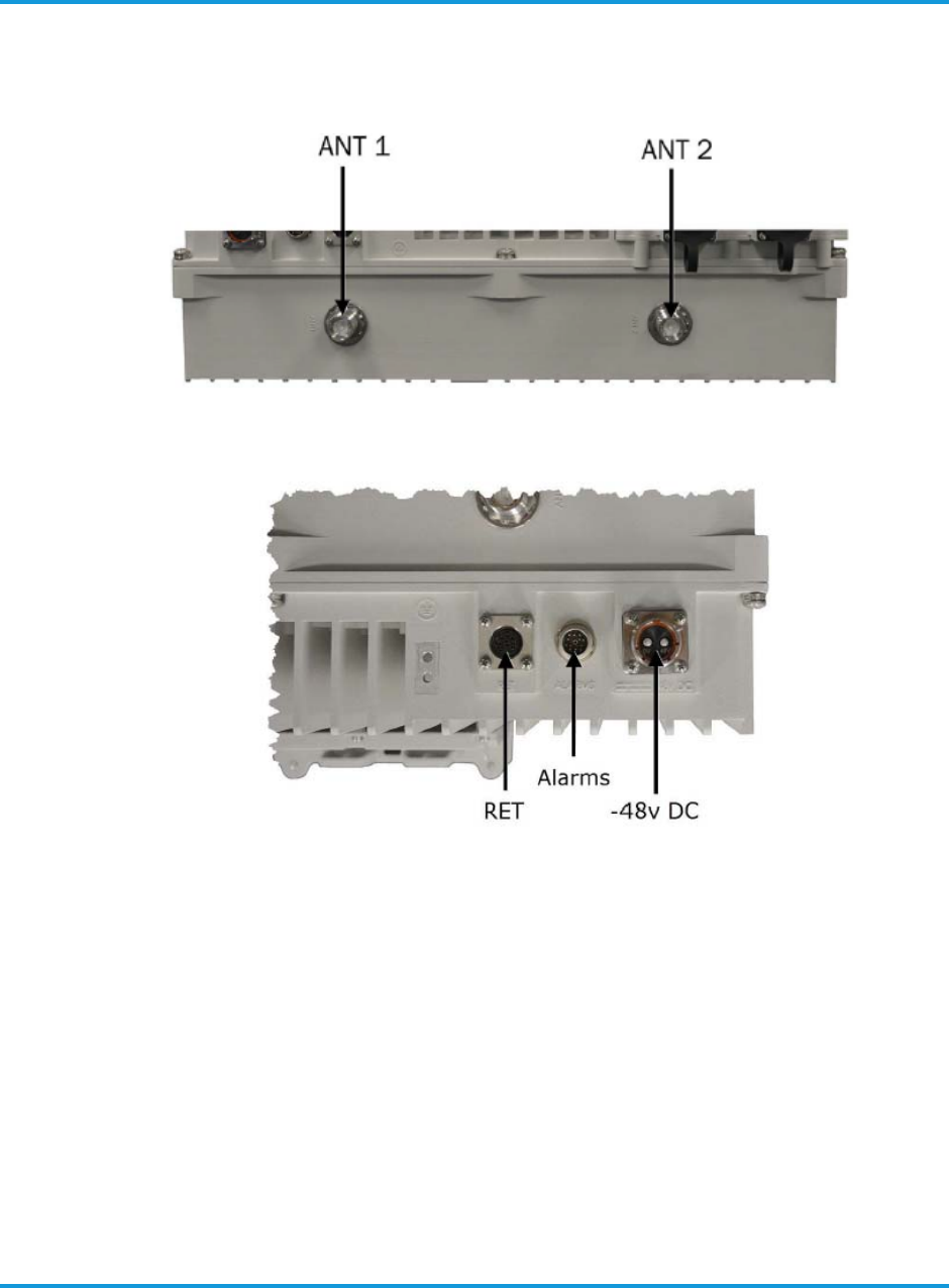
Connector locations for RF input/output are shown in Figure 3-2 iRM2249 iRRH RF
connectors location on page 3-4. Connector locations for –48 V DC Power and
Remote Electrical Tilt are shown in Figure 3-3 iRM2249 iRRH RET and –48VDC
(power) connector location on page 3-4. Connector locations for GPS antenna and
Item Specification
Environmental
Working temperature (non-condensing
humidity
–40° to 131° F (–40° to 55° C)
Operating altitude –197 to 9,843 ft (–60 to 3000 m)
Relative humidity 5 to 100%
Cooling Convection (fanless)
Table 3-1 Altiostar Networks iRM2249 iRRH technical specifications (continued)
Physical description
iRM2249nn00-1 iRRH Product Description and Installation Guide 3-5
Figure 3-4 iRM2249 iRRH GPS and fronthaul connectors location
Figure 3-5 iRM2249 iRRH ground connector location

Physical description
3-6 iRM2249nn00-1 iRRH Product Description and Installation Guide
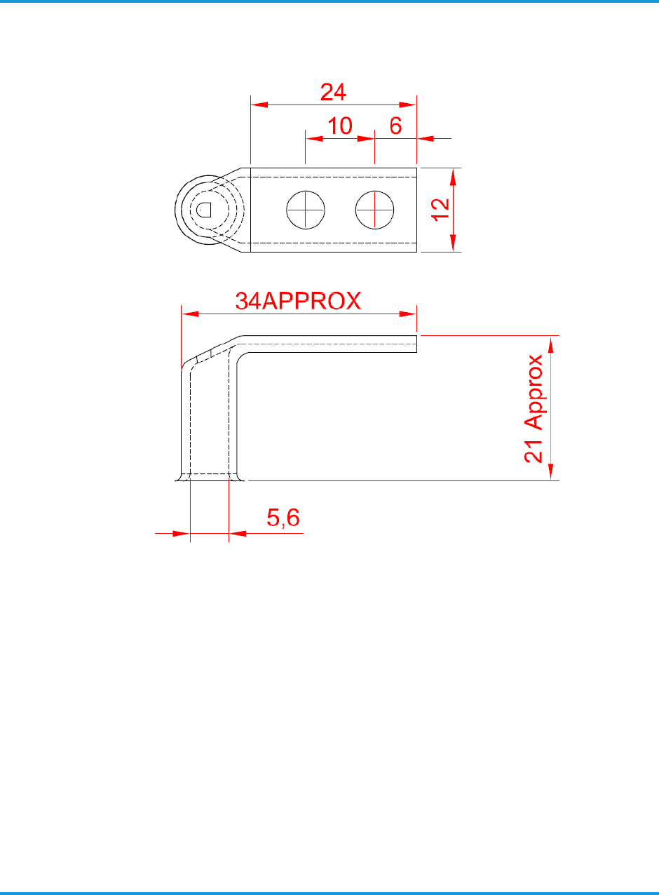
3.2.1 Grounding terminal lug
The grounding cable and ground bonding hardware is supplied by the installer.
The installer pre-assembles the grounding cable prior to routing to the
iRM2249. However, the grounding terminal lug is supplied with the iRM2249.
Figure 3-5 iRM2249 iRRH ground connector location on page 3-5 shows the
details the grounding terminal lug. To install the grounding terminal lug refer
to Verify Installer-supplied grounding cable on page 6-2.
Table 3-2 iRM2249 iRRH connectors
Connection Control/Connector Type Quantity Function
–48v DC
Rosenberger 2-pin
connector (PN 99K73E-
199N1)
1Power input
(GND) Dual-hole lug terminal 1Equipment grounding
GPS N (female), 50 1 Timing source input
RET 8-pin circular DIN 1
Provides +24 V DC and RS5
control function for AISGv2.0-
compliant antenna remote
electrical tilt
FH1 Gigabit Ethernet optical
MM SFP modules (PN:
FTLF8519P3BTL) or SM SFP
module (PN: FTLF1318P3BTL),
Rosenberger
Fiber Enclosure (RFE)
flange (PN: 98Z405-K00)
1
Fronthaul data
FH2 1
ANT1–ANT2 4.3-10 conn (female)
threaded coupling, 50 2RF to directional antennas
ALARMS
Lumberg 03 series, 12-pin screw-
lock circular DIN connector
(Lumberg PN: 0315 12)
1Alarms aggregation
Physical description
iRM2249nn00-1 iRRH Product Description and Installation Guide 3-7
Figure 3-6 Grounding terminal lug details
3.2.2 GPS connector
There is a 50 GPS N-female connector located on the bottom of the iRM2249
iRRH as shown in Figure 3-4 iRM2249 iRRH GPS and fronthaul connectors
location on page 3-5.
A GPS mounting kit is provided which allows mounting the GPS antenna on the
macro iRRH or, if required, in a remote location if it is necessary to obtain an
unobstructed view of the sky. The kit will include a bracket with mounting
fasteners, and a GPS antenna with integrated cable terminated with an N-male
connector in a length specified in the Site Plan.
For installations where multiple equipment share a remote antenna, the
Installer must supply any splitter/combiner/amplifier and other additional GPS
cables, connectors or hardware as required in the Site Plan.
The GPS cable bend radius is 0.75 in (19 mm).
Physical description
3-8 iRM2249nn00-1 iRRH Product Description and Installation Guide
3.2.3 RF connectors
There are four 50 4.3-10 female RF jacks that terminate on the bottom of
the iRM2249 (see Figure 3-2 iRM2249 iRRH RF connectors location on page 3-
4). They are marked, from left to right, ANT1 through ANT2. The RF cables
are supplied and pre-installed by the Installer in lengths according to site
requirements.
The 4.3-10 RF jack screw connector is secured by torquing the coupling nut to
44.25 in-lb (5 Nm) using a torque wrench.
NOTE
The Installer is also responsible for determining the antenna type, and supplying
and pre-installing the antennas at the site.
The recommended RF jumper cable is an IP-68 compliant, Amphenol 4.3-10,
male to 7/16 DIN male, with super flex cable (Part No. AAS-12HF-43SMDM-
xM). The variable x is the length of the jumper in meters, where x = 1.0, 2.5,
or 5.0. The RF jumper cable minimum bend radius is 1.2 in (30 mm).
NOTE
It is recommended that all RF cables be PIM-tested on site to ensure acceptable
performance.
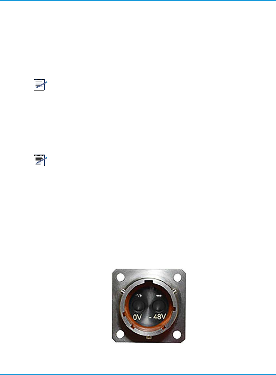
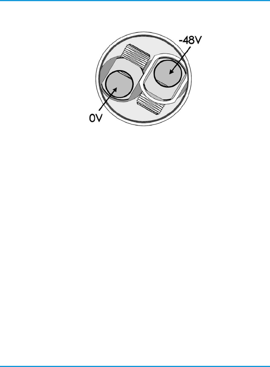
3.2.4 Power connector
–48 V DC power to the iRM2249 iRRH is through a 2-pin, EMI shielded, circular
twist-lock quick connect bulkhead jack, Rosenberger (99K73E-199N1). The
connector is keyed to prevent mis-mating. The input pins are isolated from the
chassis. The power connector pin assignments, as viewed from the bottom of
the iRM2249, are shown in Figure 3-7 –48 V DC 2-pin Rosenberger bulkhead
jack on page 3-8.
Figure 3-7 –48 V DC 2-pin Rosenberger bulkhead jack
Physical description
iRM2249nn00-1 iRRH Product Description and Installation Guide 3-9
The isolated input allows the iRRH to be connected with a 2-wire or 3-wire
supply. Altiostar recommends a 2-wire connection with the +ve connection
referenced to chassis ground at the power connector. This is indicated in Figure
3-7 –48 V DC 2-pin Rosenberger bulkhead jack on page 3-8. To facilitate the
2-wire connection, the supplied cable connector has the positive cable terminal
connected to the connector body.
The Rosenberger 99S73B-199N1 cable connector supports the 2-wire
connection. If an isolated supply (3-wire connection) is required, then an
alternative Rosenberger 99S73J-199N1 cable connector is available.
The mating plug (Rosenberger 99S73B-199N1) is fastened by turning the
coupling nut clockwise 1/4 turn by hand until it 'clicks' into the locked position.
To remove the power plug, twist the coupling nut counter-clockwise 1/4 turn.
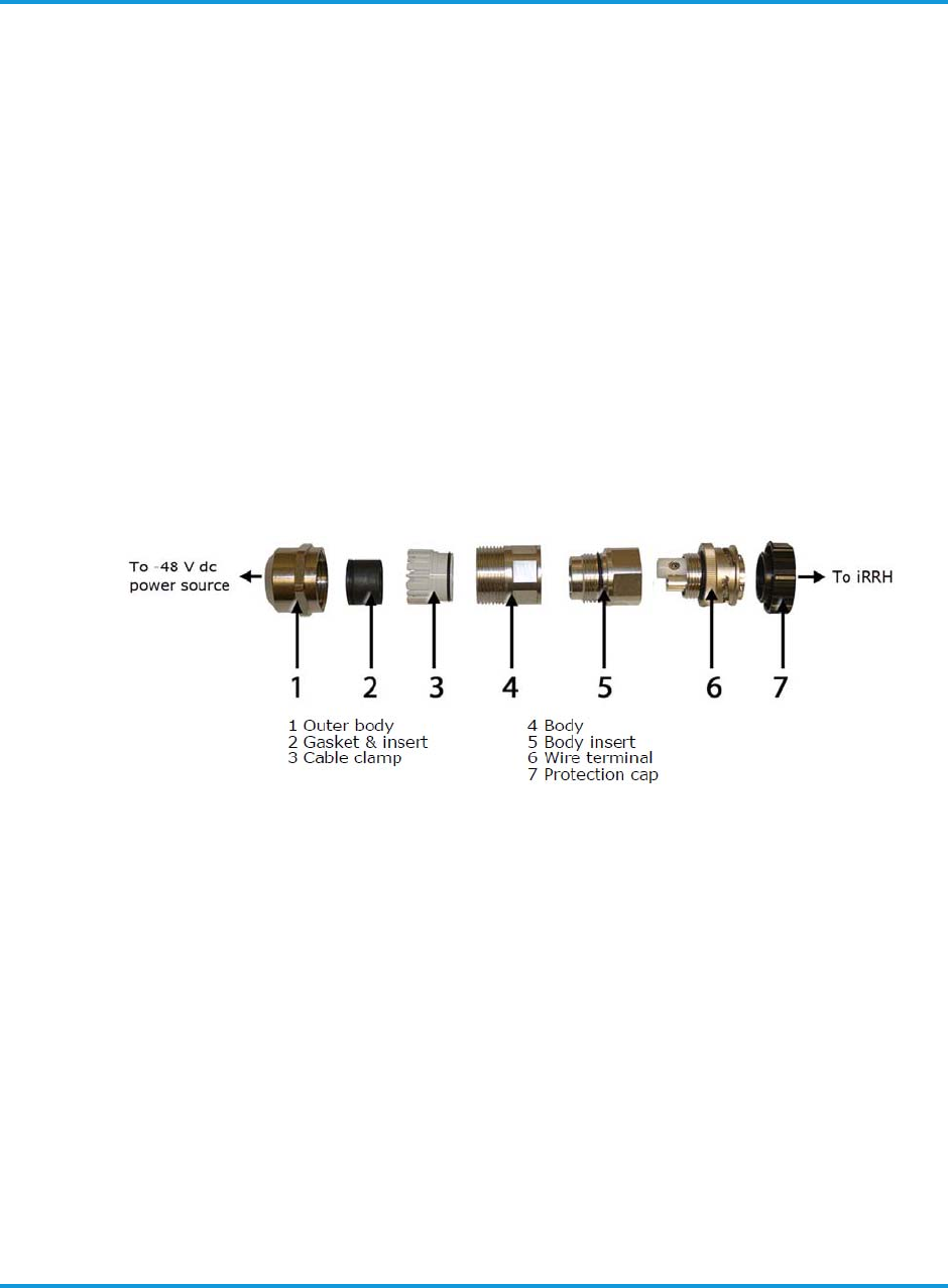
The iRM2249 comes supplied with an unconnectorized Rosenberger plug
(99S73B-199N1) in a kit (Figure 3-8 Rosenberger –48 V DC power plug
(exploded view) on page 3-9). The Installer assembles the cable onto the plug.
Assembly instructions (MA_99A5) are found in the kit with the mating plug.
Figure 3-8 Rosenberger –48 V DC power plug (exploded view)
The power source end of the plug has screw terminals for connection to
Installer-provided 8 AWG power cables. Power cable connection at the source
end of the power cable (an Installer supplied and assembled task) is shown in
Figure 3-9 Cable connection for supplied 2-pin Rosenberger plug on page 3-
10.
Physical description
3-10 iRM2249nn00-1 iRRH Product Description and Installation Guide
Figure 3-9 Cable connection for supplied 2-pin Rosenberger plug
The mating plug is fastened by turning the coupling nut clockwise 1/4 turn by
hand until it 'clicks' into the locked position. To remove the power plug, twist
the coupling nut counter-clockwise 1/4 turn.
Instructions for the connector assembly are included in the box. The Installer
must assemble the cable on site in a length ordered according to the site
requirement. Use the cable HUBER and SUHNER with part number 85013657
or equivalent.
The power cable length should be decided based on the position of the iRRH
and the DC power supply. Ensure the voltage input at the iRRH power supply
connector to be in the range of -40VDC to -58VDC. The maximum length of
the power cable should not exceed 100m to minimize the voltage drop across
the cable. The Rosenberger connector with part number 99S73B-199 or
equivalent is used with the cable. Refer to the Altiostar cable assembly drawing
360-00-0272 for details.
For assembly instructions of the power connector and cable, refer to Assembly
instructions for 2-pin power connector and cable on page A-1.
The following points list the power cable recommendations:
• Cable should be a 8 AWG minimum (to minimize any voltage drop in the
DC feed), round, 2-wire, shielded (recommended) / unshielded /co-axial
cable rated at 600 V minimum, or equivalent.
• The connector can support cables in the range AWG8-AWG16. Hence,
smaller gauge cables could be used for short feed lengths.
• Cable should have Copper or Aluminum wire gauge of approximately
10mm2 with 2 cores.
Physical description
iRM2249nn00-1 iRRH Product Description and Installation Guide 3-11
• Cable should support current per conductor >40A and resistance between
1.83 ohm/Km to 3.08 ohm/Km.
• Cable temperature range: -40degC to +90degC.
• Cable Standard: IEC 60228 class 2.
• Outer cable diameter should be in the range of 7mm to 17mm.
• Cable wires carry -48VDC and RTN.
The following points list the power connector recommendations:
• Rosenberger type power connector (99S73B-199) is always used and
comes pre-fitted to the iRRH from manufacturing.
• EMI shielded connector with a metallic body.
• 2 pins, -48VDC and RTN.
• The connector is designed so that the braided shield engages with the
metallic connector assembly to provide continuous shielding.
• RTN terminal connected to the housing.
• Use common single point grounding.
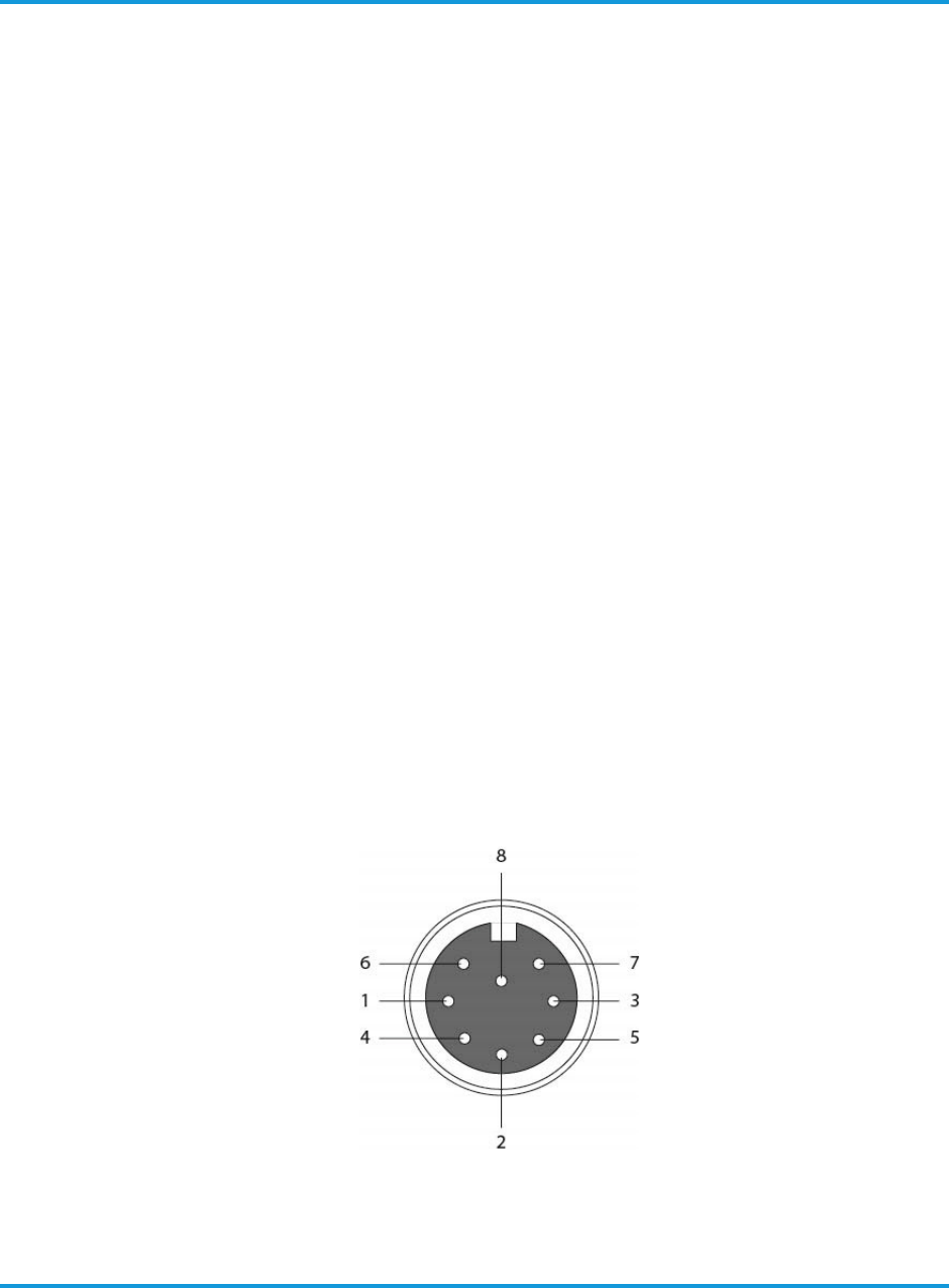
3.2.5 RET connector
The RET (Remote Electrical Tilt) bulkhead connector provides the capability of
electrical antenna control to all antennas connected to the iRM2249. Pin
assignments for the RET standard 8-pin DIN connector is shown in Figure 3-10
RET standard 8-pin DIN connector on page 3-11. The connector is keyed to
prevent mis-mating. The connector is fastened by turning the coupling nut
clockwise until hand tight.
Figure 3-10 RET standard 8-pin DIN connector
1 NC
2 NC
3 RET RS 485 B
4 NC
5 RET RS485 A
6 RET DC+24V
7 RET RETURN
8 NC

Physical description
3-12 iRM2249nn00-1 iRRH Product Description and Installation Guide
The RET cable and connectors is a standardized AISG RET Control Cable
available from many vendors. Installer supplies and installs RET cables in
lengths according to site requirements.
The RET cable can be daisy-chained to other antennas served by the iRM42249
iRRH if the option is provided by the RET motor manufacturer. Antenna RET
control is facilitated within the EMS user interface.
The Installer is responsible for providing and pre-assembly of the standardized
RET cable and connector in a length according to site requirements.
3.2.6 Fronthaul connectors
Two Gigabit Ethernet (GigE) optical SFP fronthaul ports provide connection for
up to two duplex multi-/single-mode optical GigE cables. The GigE ports,
labeled FH1 and FH2, are located on the bottom of the iRM2249 iRRH (see
Figure 3-4 iRM2249 iRRH GPS and fronthaul connectors location on page 3-5).
Connector FH1 is intended for fronthaul support. FH2 is used to daisy-chain
sidehaul support to up to one other iRM2249.
NOTE
Altiostar recommends the use of MM SFP module from Finisar –
PN: FTLF8519P3BTL or SM SFP module from Finisar –
PN: FTLF1318P3BTL for the FH1 and FH2 GigE ports.
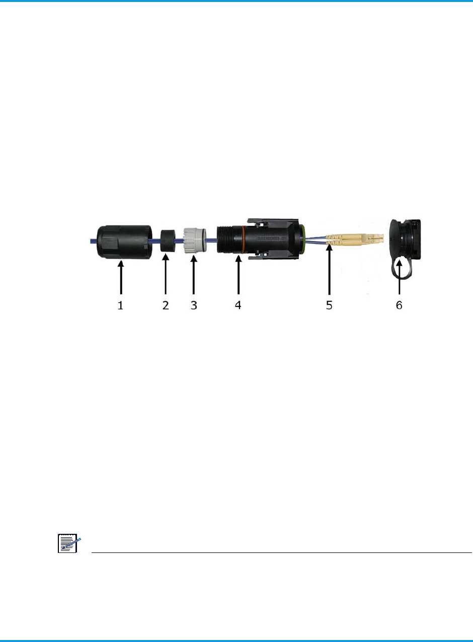
The macro iRRH is shipped with Rosenberger Fiber Enclosure (RFE) flange (PN
98Z405-K00)—a bulkhead connector with captive dust cover—installed. The
mate to the flange is the RFE ‘plug’ (Rosenberger PN 98Z105-S00) which
contain the two duplex optical GigE fiber cables and protects the fiber
connections. One (1) RFE plug is provided with the macro iRRH. They are
UL94-V0 and IP67 compliant at–40° to 158° F (–40° to 70° C).
To assemble the Rosenberger RFE plug, the threaded sealing nut is first routed
onto the fiber cable, followed by installation of a split grommet and clamping
claw onto the fiber itself (see Figure 3-11 Rosenberger RFE fiber-optic
enclosure on page 3-13 for the order of RFE assembly). The fiber cable/split
grommet/clamping claw assembly is then pressed and seated into the plug
body. Approximately 3–5 in (76–127 mm) of fiber cable, including the duplex
fiber plug, should extend beyond the outside after the RFE ‘plug’ assembly is
assembled.
The RFE plug is assembled by screwing the threaded sealing nut clockwise
until it seats into position, hand tight, on the plug body. This completes the
assembly of the RFE plug. The fiber connector is then inserted into the SFP
fiber module, which is recessed in the iRRH fronthaul port, until it ‘clicks’ into
position. Any slack fiber cable is stored inside the RFE plug. The RFE alignment
rails on the RFE plug are engaged now with the bulkhead connector. When
pushed in firmly, it ‘clicks’ into place and is locked onto the bulkhead connector
Physical description
iRM2249nn00-1 iRRH Product Description and Installation Guide 3-13
completing the installation. The RFE cannot be removed because the latch
function has been disabled by the obstruction at the latch pivot when seating
the threaded sealing nut.
To remove the RFE plug from the bulkhead connector, the plug housing must
be turned counter-clockwise until obstruction of the release latches on either
side of the plug body, has been cleared. Finally, pressing on both latches at the
same time and pulling the plug body removes the RFE from the bulkhead
connector.
For assembly instructions of the Rosenberger Fiber Enclosure, refer to
Assembly instructions for Rosenberger Fiber Enclosure on page A-4.
Figure 3-11 Rosenberger RFE fiber-optic enclosure
The dust covers over the FH1 and FH2 flanges should remain in place until the
GigE optical Ethernet cables are connected and on any unused port. The dust
covers are keyed to ensure proper installation. To remove the dust cover, just
pull it off. The dust covers are re-installed in the opposite manner.
The recommended GigE fiber optic cable (x2) is OM1 62.5/125, military fiber
cable, with dual LC/dual LC termination, 10.0 m in length and is provided by
L-Com (part no. FODLCMIL-10, or equivalent).
NOTE
Remove the dust cap only when ready to connect the cable to the iRM2249.
The GigE optical fronthaul cables are supplied and pre-installed at the site by
the Installer. Detailed assembly instructions (Rosenberger PN MA_98A1) are
supplied with each Rosenberger RFE in its packing box.
1 Threaded sealing nut 4 Plug body
2 Split grommet 5 LC-LC duplex fiber/connector
3 Clamping claw 6 Bulkhead connector
Physical description
3-14 iRM2249nn00-1 iRRH Product Description and Installation Guide
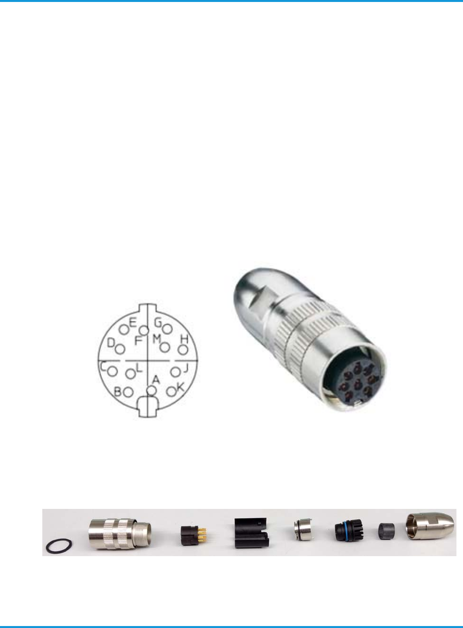
3.2.7 Alarms connector
The ALARMS connector in the iRM2249 iRRH comes pre-fitted with a Lumberg
03 series, 12-pin screw-lock circular DIN male type connector (LUMBERG PN:
0315 12). The ALARMS connector is located on the bottom of the iRM2249
and is used for aggregating alarms from equipment near the macro iRRH.
Alarm cables are assembled with a circular DIN female connector (refer to
Figure A-6 Alarms connector and cable assembly instructions on page A-5) and
then connected to an external alarm connector on the iRM2249 (as per
guidelines given in Connecting the alarms cable on page 6-13). The external
female type connector and alarms cable should be procured by the operator.
Altiostar recommends to use IP68 and ROHS compliant female, 360 degree
shielded connector; one compatible connector is Lumberg with part number
0322 12.
The Lumberg 0322 12 connector and pin assignment is shown in Figure 3-12
Lumberg 0322 12 connector and pin assignment on page 3-14.
Figure 3-12 Lumberg 0322 12 connector and pin assignment
For exploded view of the Lumberg 0322 12 connector, refer to Figure 3-13
Lumberg 0322 12 connector exploded view on page 3-14.
Figure 3-13 Lumberg 0322 12 connector exploded view

Physical description
iRM2249nn00-1 iRRH Product Description and Installation Guide 3-15
The compatible alarms cable must be a 4-pair, 23–24 AWG (0.26–0.20 mm2)
with cable OD 4–8 mm, shielded, ruggedized, oil resistant, and outdoor rated
at –40° to 131° F (–40° to 55° C), or equivalent.
Pin assignments of the pre-fitted connector on the iRRH are shown in Table 3-
3 Lumberg 0315 12 alarm connector details on page 3-15.
The Installer is responsible for supplying the cable and cable pre-assembly,
including defining the wire-color matched to pin assignments for the plug
assembly. The final wire-color pin assignments are recorded into the site log.
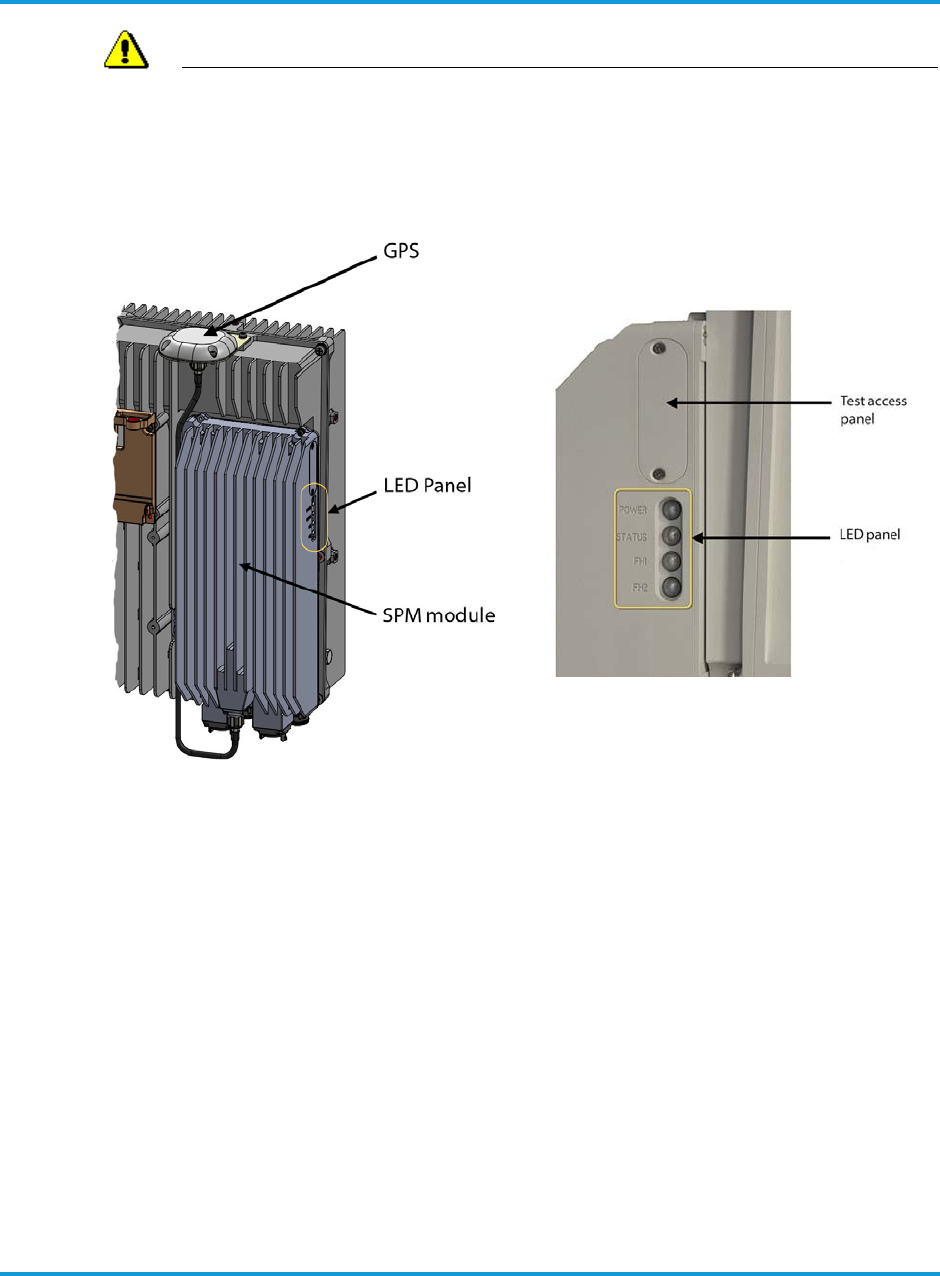
3.2.8 Access panel (factory use only)
An access panel (Figure 3-14 iRM2249 SPM module, Test Access Panel and
LED panel on page 3-16) is located on the SPM module next to the LEDs. This
panel is for factory use only.
Table 3-3 Lumberg 0315 12 alarm connector details
Pin number Pin
assignment Function
1Pin A NA
2Pin B NA
3Pin C NA
4Pin D NA
5Pin E Alarm1-A
6Pin F Alarm1-B
7Pin G Alarm2-A
8Pin H Alarm2-B
9Pin J Alarm3-A
10 Pin K Alarm3-B
11 Pin L Alarm4-A
12 Pin M Alarm4-B
Physical description
3-16 iRM2249nn00-1 iRRH Product Description and Installation Guide
WARNING
DO NOT OPEN THE ACCESS PANEL. The access panel is for factory use
only. Opening the access panel will compromise the integrity of the
weather-tight seal and void the warranty.
Figure 3-14 iRM2249 SPM module, Test Access Panel and LED panel
3.2.9 LED indicators
There are four LED indicators located on the right side of the iRM2249 iRRH as
shown in Figure 3-14 iRM2249 SPM module, Test Access Panel and LED panel
on page 3-16. Each LED can be either off, green, amber or red. The description
and operating characteristics of each LED is described in Table 3-4 LED
indicators description and operating characteristics on page 3-17. The blink
rates for the LEDs are described in Table 3-5 LED blink rates on page 3-17.
Table 3-6 LED indicators boot-up sequence on page 3-18 describes the LED
lighting sequence during boot-up.

Physical description
iRM2249nn00-1 iRRH Product Description and Installation Guide 3-17
Table 3-4 LED indicators description and operating characteristics
Indicator Description Operation
POWER Indicated power ON/OFF status
• OFF when no power is applied to the unit
• Steady GREEN when power to the unit is
normal/in service
• Steady RED when a power fault is present
STATUS Indicates the status of the
iRM2249
• OFF when no power is applied to the unit
• Steady GREEN when GPS or 1588V2 timing
synchronization lock is achieved
• Slow GREEN blink when booting up or
shutting down
• Steady AMBER when minor fault occurs
(hardware or software)
• Steady RED when a critical or major fault
occurs (hardware or software)
FH1
Indicates the status of the
Ethernet fronthaul data Port 1
throughput
• OFF when no power is applied to the unit or
when booting
• Steady GREEN when port has link and
operating at Gigabit Ethernet rate, but there
is no Ethernet activity
• Slow GREEN when port is operating at
Gigabit Ethernet rate and has Ethernet
activity
• Steady AMBER when less than Gigabit
Ethernet mode
• RED when a critical fault occurs
FH2
Indicates the status of the
Ethernet fronthaul data Port 2
throughput
Future use
*Refer to LED callouts in Figure 3-14 iRM2249 SPM module, Test Access Panel and LED panel on
page 3-16.
Table 3-5 LED blink rates
Indicator state Description
Steady OFF LED OFF
Steady ON LED is continuously ON, no interruption
Slow blink LED ON for about 0.5 s and OFF for about 0.5 s

Physical description
3-18 iRM2249nn00-1 iRRH Product Description and Installation Guide
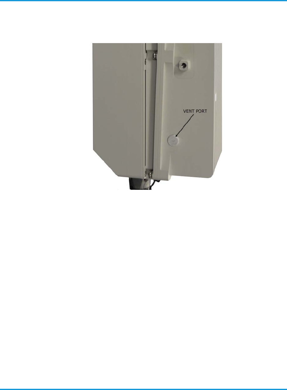
3.2.10 Vent port
A gas permeable vent has been installed on the iRM2249 iRRH to help equalize
air pressure inside the enclosure and prevent contaminants such as water, salt
and dust from getting inside (see Figure 3-15 Vent port on page 3-19). The
vent fitting has a gas-permeable membrane integrated into a screw-in fitting.
It meets the IEC 60529 standard for enclosure ingress protection against
Fast blink Varying blink rate, noticeably faster than a slow blink rate (used only as a
location aid/unit ID)
Table 3-5 LED blink rates (continued)
Indicator state Description
Table 3-6 LED indicators boot-up sequence
Time (mm:ss) Indicator name
POWER STATUS FH1 FH2
—OFF OFF OFF
OFF
00:01 Fast blink OFF OFF OFF
00:02 Steady ON Green OFF OFF OFF
00:03 Steady ON Red OFF OFF OFF
00:04 OFF OFF OFF OFF
00:10 Fast blink OFF OFF OFF
00:11 Steady ON green OFF OFF OFF
00:16 * OFF Slow/Fast flash green OFF
00:60 * Slow flash green Slow/Fast flash green OFF
02:30 Steady ON green Steady ON green Slow/Fast flash green OFF
NOTE: Assumes FH1 is connected and FH2 is not connected. Initial state (—) is power OFF. * means
state remains as previously indicated. GPS lock is achieved at 02:30 as indicated by STATUS LED being
Steady On green.
Physical description
iRM2249nn00-1 iRRH Product Description and Installation Guide 3-19
particulates and liquids. The vent should function maintenance-free over the
lifetime of the iRM2249.
Figure 3-15 Vent port

Physical description
3-20 iRM2249nn00-1 iRRH Product Description and Installation Guide

Installation prerequisites
iRM2249nn00-1 iRRH Product Description and Installation Guide 4-1
4 Installation prerequisites
This section contains information on the documentation, tools, equipment, and
conditions required for performing the installation procedure. The document assumes
that the target audience has reasonable industry experience, is qualified, and has
installed wireless base stations in the past.
4.1 Required tools
A typical telecommunications technician's toolkit is required to complete the
iRM2249 installation. Additional required specialty tools and consumables are
listed in Table 4-1 Required tools on page 4-1.
Table 4-1 Required tools
Required Tools
ESD wrist grounding
strap
Torque screwdriver
and assorted bits
Box cutter Digital voltmeter
Torque wrench, open-
end, 8 mm
Crimp tool (2 to 8
AWG)
Socket set, plus
additional socket
wrench
Wrench, 3/4 in (19
mm)

Installation prerequisites
4-2 iRM2249nn00-1 iRRH Product Description and Installation Guide
Cordless electric
screwdriver Cable tie tool
Nylon bridle sling, 2-
leg, 2 in (5.1 mm)
straps, 6×19 EIPS, or
equivalent
Pulley-minimum
load-bearing
capacity 880 lb (400
kg)
Punch Wire stripper
Rope - minimum
breaking strength
600 lb (272 kg)
Self-amalgamating
waterproofing tape
(e.g., Commscope
Miracle Tape,
Huber+Suhner Fast-
Wrap, RFS CELL-
Tape, EasyWrap®
tape, etc.)
Spirit level Tape measure
Assorted hook & loop
fasteners (for fiber
optic cables) and cable
ties (for all other
applications)
Torque wrench for
7/16 conn, 32 mm,
211 in-lb
(25 Nm)
Table 4-1 Required tools (continued)
Required Tools
Installation prerequisites
iRM2249nn00-1 iRRH Product Description and Installation Guide 4-3
4.2 Required site equipment
This section describes the additional interconnecting equipment required for the
installation of the Altiostar Networks iRM2249. These are essentially cables,
connectors and fixing arrangements. The specification of these items may need to
be customized on site by the Installer (specifically the type and length of cables).
Refer to Table 3-2 iRM2249 iRRH connectors on page 3-6 when ordering and
customizing the following items:
• Grounding cable between the iRRH and the local grounding point. Altiostar
Networks provides the two-hole lug for crimping onto the cable.
• Power cable between the iRRH and local DC supply. Installer must provide
suitable lightning and surge suppression devices on the power line to the unit
(minimum 20 kA-rated device recommended). We recommend one lightning
and surge suppressor be installed close to the iRRH on the tower/pole/wall and
one on the cable entrance just before it enters the facility.
• Optical fiber cables between iRRH and transport network.
Other than lightning and surge suppression devices, Table 4-2 iRM2249 iRRH
Installer-supplied parts list on page 4-4 provides a list of the Installer-supplied
interconnection equipment required to install the iRM2249.
NOTE
Some parts have an order lead-time of up to 10 weeks. It is important that
these items be ordered as soon as possible in the planning phases of the iRRH
installation so that they are available on-site at the time of installation.
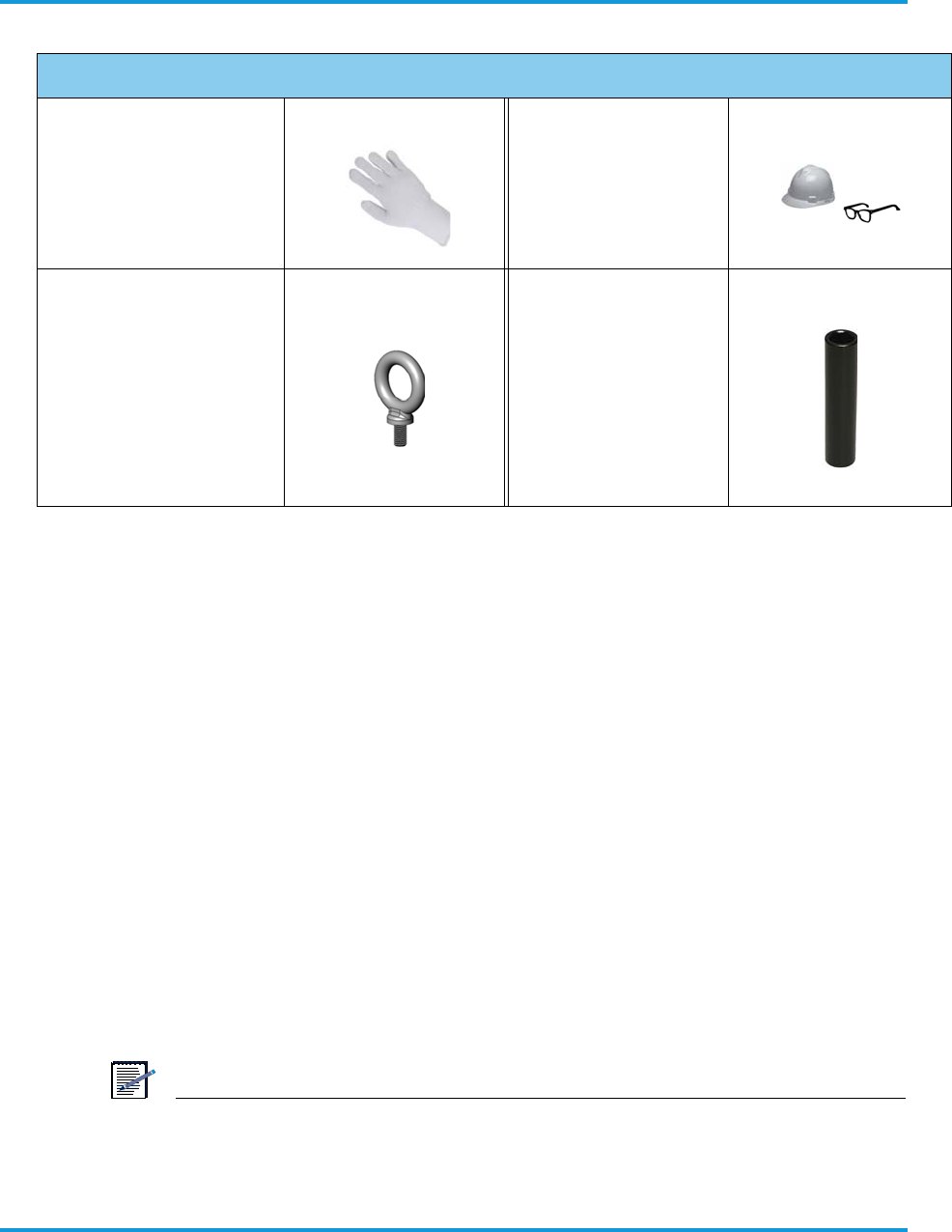
Insulating gloves (for
lifting hot unit)
Hardhat, eye
protection and other
safety apparatus
Eyebolts (McMaster
Model 3040T13, or
equivalent)
M8 ×1.25, 16mm,
quantity 2 (lifting) and
1 (guiding) minimum
1/2-in drive, 3/4 in
(19 mm) extra deep
well sockets, 5 in
(127 mm) min
internal depth.
Quantity 2, for
accessing mounting
bracket M12 bolts.
Table 4-1 Required tools (continued)
Required Tools

Installation prerequisites
4-4 iRM2249nn00-1 iRRH Product Description and Installation Guide
Table 4-2 iRM2249 iRRH Installer-supplied parts list
4.3 Site preparation
It is a critical that the conditions in this section must be fulfilled before starting
work at the site.
4.4 Site pre-installation visit checklist
To verify site conditions required for the installation of the iRRH are known, a pre-
installation visit, attended by the Operator's representative, the Installer,
Altiostar Networks, and other required parties, must be performed. Tasks required
Qty Part Part number Part description
Installer-acquired parts for pre-installation requirements
1
Splitter/
combiner/
amp/cable
As specified per
site requirement
Any splitter/combiner/amp/cable required for
shared remote antenna.
1Power cable
As specified per
site requirement
Power cable, 8 AWG min., shielded, round
cable. Refer to Power connector on page 3-8
(Installer orders to length according to site
requirement.)
1
GigE duplex
multi-/
singlemode
fiberoptic
cable
L-Com (part no.
FODLCMIL-nn, or
equivalent)
GigE duplex multi-/single-mode
fiber-optic cable, OM1 62.5/125,
military fiber cable, with dual LC/
dual LC terminations, length sized to
site requirement (model number
shown is for 10 m cable). For
additional information. Refer to Fronthaul
connectors on page 3-12.
1
AISG RET
control
cable
As specified per
site requirement
AISG RET control cable with 8-pin DIN
connector in required length. Refer to RET
connector on page 3-11.
1 per 4
External
alarms
Alarm cable As specified per
site requirement
4-pair, shielded, outdoor-rated, round alarm
cable. For additional information, Refer to
Alarms connector on page 3-14.
3
(min)
Eyebolt for
lifting
McMaster
3040T13T
(or equiv)
Eyebolt, M8x1.25, 16 mm, SS (third eyebolt to
be used for control line [guide] attachment).

Installation prerequisites
iRM2249nn00-1 iRRH Product Description and Installation Guide 4-5
to be accomplished should include, at a minimum, those listed in Table 4-3 Site
pre-installation visit checklist on page 4-5.
Table 4-3 Site pre-installation visit checklist
Item Site pre-installation visit checklist Check
1Verify Site Installation Plan and installation documentation is available.
2Verify health and safety documentation specified by the Operator and Altiostar Networks
are understood and installation personnel are trained accordingly.
3Know locations of fire equipment, eyewash stations, and evacuation procedures posted
for fire/halon discharge.
4Know locations of first aid and emergency equipment and installation personnel are
familiar with their operation and use.
5Verify site authorizations, clearances, and releases from Operator and local authorities
are complete.
6Verify emergency telephone numbers are posted for fire, police, and ambulance/medical
aid.
7Verify contact information for the Operator or his representative(s), the Installer, and
local authorities are posted.
8Verify installation schedule is approved.
9Wear approved protective equipment such as hard hats, safety glasses, gloves, etc.
when needed.
10 Verify the installation location of the iRRH meets the mounting requirements indicated in
this document.
11
Verify main power supply is properly installed and tested and capable of supplying the
required voltage (–58 –48.0 –40 V DC) and current for proper operation of the
iRRH.
12 Verify –48 V DC power cable to the iRRH is labeled and tested as specified in the Site
Installation Plan.
13 Verify recommended size breakers/fuses for the external power source is properly
installed and capable of protecting the –48 V DC power to the unit.
14 Verify earth ground bonding point, for connection of the grounding cable to the iRRH is
correctly installed, labeled and tested as specified in the Site Installation Plan.
15 Determine a safe method to hoist and secure iRRH into position on selected structure
and enter into Site Installation Plan.
16 Verify proper in-line surge protectors are installed, where required, on power and RET
cables as specified in the Site Installation Plan.
17
Verify that the Operator, Installer, Altiostar Networks and all other affected parties are in
agreement with the equipment installation location, power source, and grounding
location, to meet the installation checklist requirements.

Installation prerequisites
4-6 iRM2249nn00-1 iRRH Product Description and Installation Guide
4.5 Site installation checklist
Verify site conditions required for the installation of the iRRH are known. In
addition, the site must be prepared by the Installer in accordance with the Site
Installation Guide provided by the Operator which must include, at a minimum,
the required tasks in Table 4-4 Site installation checklist on page 4-6.
Table 4-4 Site installation checklist
Item Site installation checklist Check
1 Verify Site Installation Plan and installation documentation is available.
2Verify health and safety documentation specified by the Operator and Altiostar
Networks are understood and installation personnel are trained accordingly.
3Know locations of fire equipment, eyewash stations, and evacuation procedures
posted for fire/halon discharge.
4Know locations of first aid and emergency equipment and installation personnel
are familiar with their operation and use.
5Verify site authorizations, clearances, and releases from Operator and local
authorities are complete.
6Verify emergency telephone numbers are posted for fire, police, and
ambulance/medical aid.
7Verify Operator or his representative(s), the Installer, and local authorities
contact and phone numbers are posted.
8 Verify installation schedule is approved.
9Wear approved protective equipment such as hard hats, safety glasses, gloves,
etc. when needed.
10 Verify pre-installation work specified in the Site Installation Plan is complete.
11 Verify the installation location of the iRRH meets the mounting requirements
indicated in this document.
12 Verify all required tools required for lifting the iRRH onto structure, and for
installation, are available.
13 Verify all ordered hardware, including that not provided as part of the Altiostar
Networks intelligent eNodeB solution, is available and on site.
14
Verify that the Operator or his representative(s), the Installer, Altiostar
Networks, and all other affected parties are in agreement with the
equipment installation location, power source, and grounding location,
to meet the installation checklist requirements.
15
Verify proper in-line surge protectors are installed, where required, on
–48 V DC power and RET cables as specified in the Site Installation
Plan.

Installation prerequisites
iRM2249nn00-1 iRRH Product Description and Installation Guide 4-7
16 Verify recommended size wire is installed in the external power source
supplying –48 V DC power to the unit.
17
Verify custom pre-assembled cables, custom cables, wires and other
material are properly labeled, installed and tested according to system
and site requirements as specified in the Site Installation Plan.
18 Verify earth grounding of the chassis/rack hosting the iRRH is correctly
installed, using the correct size/type wire, and is tested.
19
Verify main power supply is properly installed and tested and capable of
supplying the required voltage (–58 –48.0 –40 V DC), and current
for proper operation of the iRRH.
20
Verify all cables are neatly routed through cable ladders, cable trays
and ducts, are secured with cable ties/wraps, and dressed according to
local practice.
Table 4-4 Site installation checklist (continued)
Item Site installation checklist Check

Installation prerequisites
4-8 iRM2249nn00-1 iRRH Product Description and Installation Guide

Installation overview
iRM2249nn00-1 iRRH Product Description and Installation Guide 5-1
5 Installation overview
This section provides an overview of the installation procedures and instructions for
installing the Altiostar Networks iRM2249 intelligent Remote Radio Head.
All required cabling for grounding, power, fronthaul, RF and optional GPS, are supplied
by the Installer, as provided in the Site Installation Plan, and should already be pre-
installed with drops to the iRRH location, or according to local practice.
5.1 Installation procedures
The following list describes the top-level iRM2249 installation procedures. You can
instantly navigate to any procedure by clicking on the procedure with the mouse.
•Unpacking the shipping container on page 5-1
•Verifying all parts received on page 5-2
•Assembling cables on page 6-1
•Verify Installer-supplied –48 V DC power cable on page 6-1
•Verify Installer-supplied GigE optical cable on page 6-1
•Verify Installer-supplied grounding cable on page 6-2
•Routing pre-assembled power/GigE optical fronthaul/grounding cables on
page 6-3
•Mounting on a pole/mast on page 6-4
•Mounting on a wall on page 6-5
•Hoisting the iRM2249 on elevated structures on page 6-6
•Installing the iRM2249 on the mounting bracket on page 6-7
•Connecting the grounding cable on page 6-10
•Connecting the RET cables on page 6-11
•Connecting the GigE optical fronthaul cables on page 6-12
•Connecting the RF cables on page 6-12
•Connecting the alarms cable on page 6-13
•Connecting the –48 V DC power cable on page 6-13
•Weatherproofing cable connections on page 6-14
•Checking power on page 6-15
5.2 Unpacking the shipping container
The following procedure describes removing the iRRH from the shipping container,
inspecting the contents for damage, and what to do if damage is found.

Installation overview
5-2 iRM2249nn00-1 iRRH Product Description and Installation Guide
Procedure 5-1 To unpack the shipping container
1. Verify no shipping damage to box.
NOTE
It is important to report damage or material shortages to the shipping carrier
while a representative is on site. If concealed damage or material shortages are
found at a later time, contact the shipper to make arrangements for inspection
and claim filing.
2. Remove packing materials.
NOTE
The shipping materials can be recycled. In some regions or countries it is
mandatory that packing materials be recycled or re-purposed. Please dispose of
shipping material accordingly.
3. Remove equipment from packing material and inspect equipment for shipping
damage or missing items.
NOTE
If concealed damage or material shortages are found at a later time, contact the
shipper to make arrangements for inspection and claim filing.
5.3 Verifying all parts received
Verify all parts listed in the accessory list in Table Verify all parts listed in the
accessory list in are received. on page 5-2 are received.
Table 5-1 iRM2249 iRRH parts list
Qty Altiostar part number Part description
1
509-20-0001
509-21-0002
509-22-0002
509-25-0001
509-26-0001
iRM2249, Band 20, 2T2R, 80W, MM SFP
iRM2249, Band 3, 2T2R, 60W, MM SFP
iRM2249, Band 7, 2T2R, 60W, MM SFP
iRM2249, Band 12 Macro, w/GPS
iRM2249, Band 5, Macro, w/GPS
1
340-00-0075
340-00-0074
340-00-0073
340-00-0094
340-00-0102
TOP LVL ASSY, ALDEBARAN, RADIO, 800
TOP LVL ASSY, ALDEBARAN, RADIO, BAND 3, 1800
TOP LVL ASSY, ALDEBARAN, RADIO, 2600
TOP LVL ASSY, ALDEBARAN, RADIO, Band 12 (700MHz)
TOP LVL ASSY, ALDEBARAN, RADIO, Band 5 (850MHz)
1 per Radio
module 350-00-0033 KIT,ACCESSORY, iRRH CHASSIS
1 100-00-0213 Conn, EMI Shielded 2 Way Cable Plug, 99S73B-199N1
2 100-00-0222 Conn, Fiber Enclosure, Fits 4.5-9.0mm Cable, UL94-V0, IP67, -40-70C

Installation overview
iRM2249nn00-1 iRRH Product Description and Installation Guide 5-3
1 350-00-0007 KIT,STANDARD KIT,MOUNT HARDWARE & SCREWS,OUTDOOR
EQUIPMENT
1 402-00-0017
LBL, Part Number and Revision, 44.45mm X 19.05mm, White.Polyesther
4 445-00-0003 NUT,M12-1.75,18-8 STAINLESS STEEL
1 455-00-0022 PKG, RECLOSABLE CLEAR BAG 2x8IN 4 MIL THK
2 460-00-0014 SCREW,M4X0.7,12MM,PHILIPS PAN HEAD,SPLIT/PLAIN
WASHER,SEMS,316 STAINLESS STEEL,PLAIN FINISH
2 460-00-0020 SCW,M12-1.75 x168MM STUD,18-8 STAINLESS STEEL
4 495-00-0001 WSH,PLAIN,M12,OD 24MM MAX,T=2.5MM MAX,18-8 STAINLESS
STEEL
4 495-00-0002 WSH,SPLIT,M12,OD 21.1MM MAX,T=2.5MM MAX 18-8 STAINLESS
STEEL
1 350-00-0009 KIT,ACCESSORY KIT,LUGS & NUTS,RRH
1 402-00-0017 LBL, Part Number and Revision, 44.45mm X 19.05mm, White.
Polyesther
1 440-00-0033 LUG, #6 AWG, 2 HOLE, 10MM BOLT SP, 24MM L, 90 DEG, COPPER,
ELECTRO TIN PL
1 455-00-0023 PKG, RECLOSABLE CLEAR BAG 2x2IN 4 MIL THK
3 460-00-0017 SCREW,M5-0.8 X10MM,PHILIPS PAN HEAD,SPLIT/PLAIN
WASHER,SEMS,316 STAINLESS STEEL,PLAIN FINISH
1 402-00-0017 LBL, Part Number and Revision, 44.45mm X 19.05mm, White.
Polyesther
1 455-00-0024 PKG, RECLOSABLE CLEAR BAG 6x10IN 4 MIL THK
2 per Radio
module 402-00-0033 LBL, PACKAGING BOX, GENERIC
1 per Radio
module 420-00-0030 FABM,PRESSED,AUXILLARY POLE BRACKET,4T4R,RRH,10W-
PATH,2300MHZ
1 per Radio
module 420-00-0109 FABM, CAST MACHINED, UNIVERSAL MOUNT BRACKET,
OUTDOOR EQUIPMENT
1 per Radio
module 456-00-0020 Pkg Set, Aldebaran Chassis and Shield, Skid,Top/Bottom
pads,Corrugated box w/artwork
Table 5-1 iRM2249 iRRH parts list (continued)
Qty Altiostar part number Part description

Installation overview
5-4 iRM2249nn00-1 iRRH Product Description and Installation Guide

Installing the iRM2249
iRM2249nn00-1 iRRH Product Description and Installation Guide 6-1
6 Installing the iRM2249
This section provides the procedure for installing the iRM2249 macro iRRH in remote
locations such as on towers, poles, masts, walls, roofs, or other structures utilizing a
universal mounting assembly.
Instructions for making connections to external interfaces, cabling, grounding and
power are also provided.
6.1 Assembling cables
The Installer will need to order, pre-assemble, and pre-install various cables to the
iRM2249. Refer to Required site equipment on page 4-3.
6.1.1 Verify Installer-supplied –48 V DC power cable
The Installer supplies and pre-assembles the –48VDC power connection cable.
Use an 8 AWG minimum, round, 2-wire shielded cable rated at 600 V
minimum. The power cable length should be decided based on the position of
the iRRH and the DC power supply. Ensure the voltage input at the iRRH power
supply connector to be in the range of -40VDC to -58VDC. The maximum
length of the power cable should not exceed 100m to minimize the voltage
drop across the cable.
The female plug (Rosenberger PN 99S73B-199N1), for assembly of the DC
power cable, is provided with the iRM2249 iRRH. The connection configuration
for the supply side of the power cable is determined by site specific
requirements.
6.1.2 Verify Installer-supplied GigE optical cable
The recommended GigE fiber optic cable is OM1 62.5/125, military fiber cable,
with dual LC/dual LC termination (L-Com PN FODLCMIL-xx, or equivalent,
where xx=length of cable in meters). The Installer is responsible for ordering
this cable in the appropriate length according to site requirements.
One (1) RFE plug (Rosenberger PN 98Z105-S00) is provided with the macro
iRRH. The fiber-optic cable and dual mode fiber connector is housed inside the
RFE plug. The RFE plug is essentially a shroud covering the connected fiber-
optic connector and SFP optical module inside the bulkhead on the bottom of
the iRM2249 to conform to an IP67 standard, completing the weatherproof
seal.
The RFE plug is pushed firmly into the fronthaul port flange on the bottom of
the iRM2249 until it clicks into the locked position.
Installing the iRM2249
6-2 iRM2249nn00-1 iRRH Product Description and Installation Guide
6.1.3 Verify Installer-supplied grounding cable
The grounding cable and ground bonding hardware is supplied by the installer.
The installer pre-assembles the grounding cable prior to routing to the
iRM2249. However, the grounding terminal lug is supplied with the iRM2249.
NOTE
The grounding cable to the iRM2249 should be 3.9 in (10 cm) longer than other
cables to the unit. This will maintain ground connection should the cables be
pulled off when the unit is extended beyond the length of the cables.
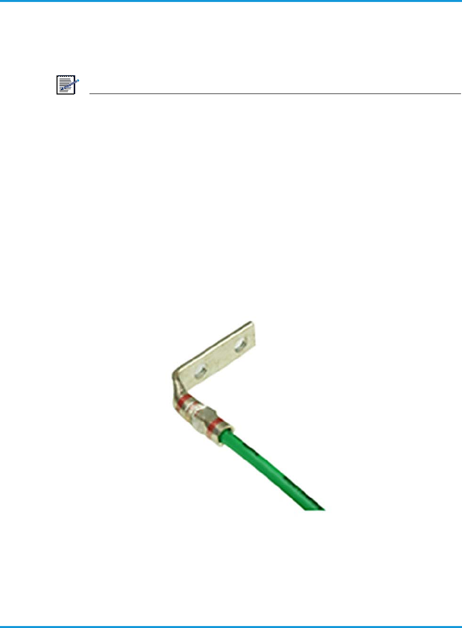
Procedure 6-1 To install ground terminal lug
1. Cut a 6 AWG (4.11 mm) stranded grounding cable the appropriate length for the
iRM2249 installation.
2. Strip away insulation from one end to expose 3/4 in (19 mm) of bare wire.
3. Crimp the dual-lug grounding terminal (supplied) to the cable using the special-
purpose crimp tool specified in a typical telecommunications technician’s toolkit.
Additional required specialty tools and consumables are listed in Table 4-1
Required tools on page 4 - 1. Table 6-1 Grounding terminal lug assembled on
grounding cable on page 6 - 2 shows an assembled cable/lug assembly.
Figure 6-1 Grounding terminal lug assembled on grounding cable
Installing the iRM2249
iRM2249nn00-1 iRRH Product Description and Installation Guide 6-3
6.2 Routing pre-assembled power/GigE optical fronthaul/grounding
cables
This procedures provides instructions for routing the pre-assembled –48 V DC
power cable, the GigE optical fronthaul cable, and the grounding cable to the
iRM2249 mounting location before assembling components.
Procedure 6-2 To route cables
1. Route the cables from the iRM2249 installation location to cable sources as shown
in Figure 6-2 iRM2249 cable routing on page 6-3.
Figure 6-2 iRM2249 cable routing
2. Secure and dress all cables according to local practice.
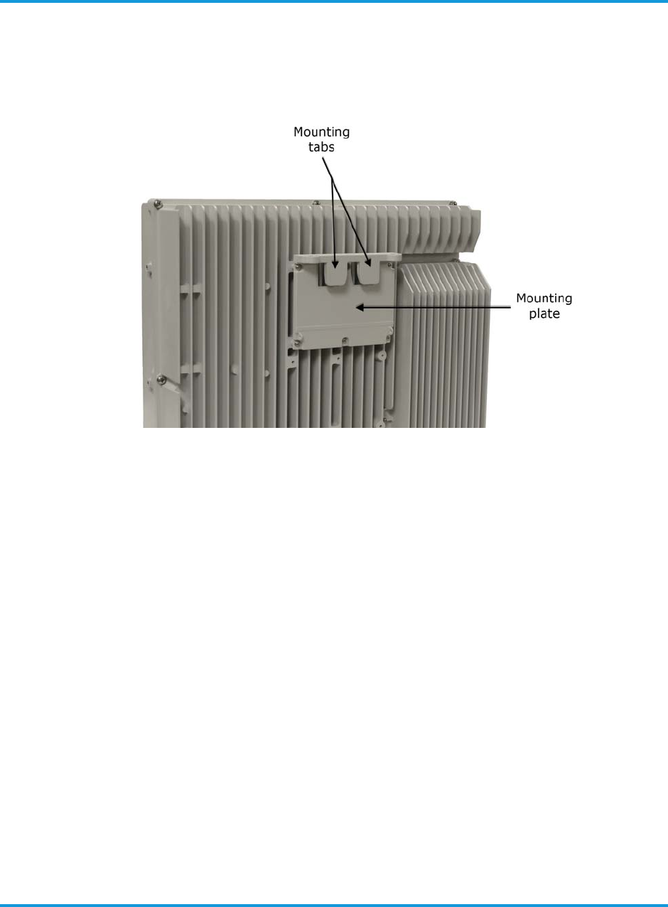
Installing the iRM2249
6-4 iRM2249nn00-1 iRRH Product Description and Installation Guide
6.3 Installing the mounting bracket
The iRM2249 is shipped from the factory with the mounting plate pre-installed on
the chassis as shown in Figure 6-3 iRM2249mounting plate on page 6-4.
Figure 6-3 iRM2249mounting plate
6.3.1 Mounting on a pole/mast
The following procedure provided instructions for mounting the iRM2249 on a
pole/mast using the supplied mounting bracket assembly.
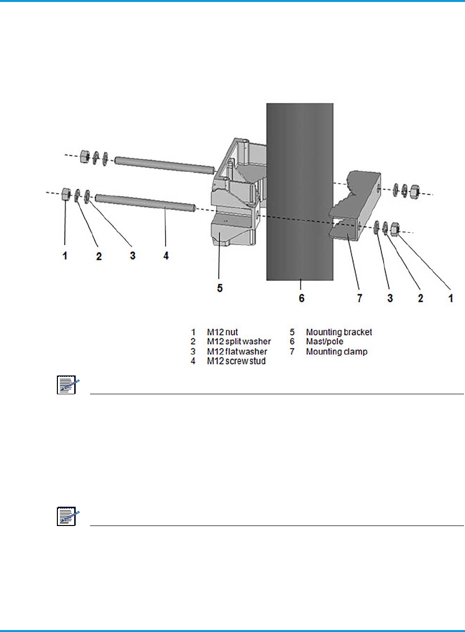
Installing the iRM2249
iRM2249nn00-1 iRRH Product Description and Installation Guide 6-5
Procedure 6-3 To install mounting plate on a pole or mast
1. Install the mounting bracket and mounting clamp onto the pole/mast with
mounting hardware as shown in Figure 6-4 Installing mounting bracket on a pole
on page 6-5.
Figure 6-4 Installing mounting bracket on a pole
NOTE
IMPORTANT! Maintain the parallel orientation of the clamp and bracket while
tightening the nuts. This will require alternating tightening the M12-1.75 nuts on
each screw stud until the final torque, 29.5 ft-lb (40 Nm) is achieved.
6.3.2 Mounting on a wall
The following procedure provides instructions for mounting the iRM2249 to a
wall or other flat, vertical surface.
NOTE
The wall where the iRM2249 is to be mounted must be able to support four
times the weight of the unit. The unit can be mounted at a deviation from
vertical of 3°.
Installing the iRM2249
6-6 iRM2249nn00-1 iRRH Product Description and Installation Guide
NOTE
The mounting clamp is not used when mounting the iRM2249 to a wall or other
flat surface. In addition, the M12 bolts supplied in the hardware kit are not used
for wall-mount applications.
NOTE
The Installer must provide two (2) M12 anchors, designed for outdoor use, that
are compatible with the type structure on which the iRM2249 is to be installed.
Procedure 6-4 To install mounting plate on a wall
1. Determine the location where the mounting bracket is to be installed.
NOTE
The center-to-center distance for drilling holes to install the selected anchor is
5.5 in (140 mm).
2. Using a tape measure and spirit level, mark where the anchor will be installed
using a center punch.
3. Drill the holes where the anchor or fastener will be installed on the wall using a
drill bit sized for the anchor or fastener, and insert anchor or fastener.
4. Install the iRM2249 mounting bracket to the wall using the two (2) selected
fasteners and supplied by the Installer.
5. Tighten the fastener to torque specified by the fastener/anchor manufacturer
using a torque wrench.
6.4 Hoisting the iRM2249 on elevated structures
Hoist line eye bolt screw inserts are located on both sides and on top of the unit.
The recommended hoist line lift points for the iRM2249 using the side screw
inserts is shown in Figure 6-5 Hoist line carabiner attachment points on page 6-7.
Installing the hoist line lift eyebolts in the screw inserts on the top of the unit (not
shown) are also recommended. These are the ONLY recommended points of
attachment when hoisting the iRM2249 into position on elevated structures.
An Installer-supplied 2-leg nylon lift sling is attached to the eye bolts and the
iRM2249 is lifted directly from the packing container to the mounting location.
WARNING
Because of the variation that may exist among mounting
environments, the Installer is solely responsible for determining
an industry-approved, safe method of hoisting the iRM2249 into
position onto elevated structures.
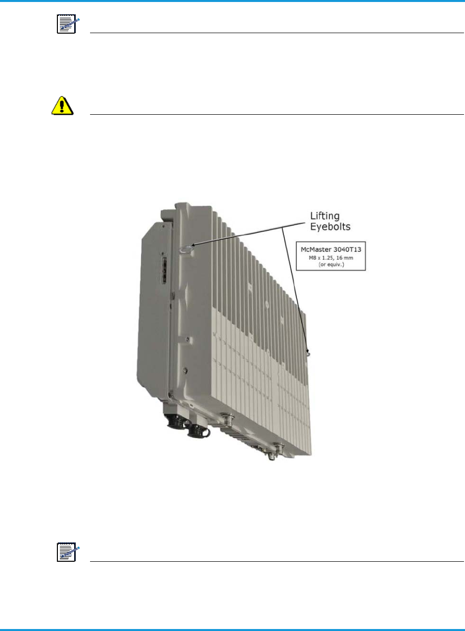
Installing the iRM2249
iRM2249nn00-1 iRRH Product Description and Installation Guide 6-7
NOTE
A tag line, to control sway during the lift, can be attached to either eye bolt, or a
third eyebolt can be installed in one of the unused screw inserts located on the
sides of the unit.
WARNING
Be sure to follow all established local practice and safety
precautions when hoisting the equipment on elevated
structures.
Figure 6-5 Hoist line carabiner attachment points
6.5 Installing the iRM2249 on the mounting bracket
This section provides the procedure for installing the iRM2249 main unit on the
installed mounting bracket.
NOTE
While installing the iRM2249 iRRH, care must be taken to ensure that the unit is
vertically mounted with sufficient gap around the unit to allow for convection
cooling. Also, ensure that the GPS antenna has a clear view of the sky for
maximum signal reception.
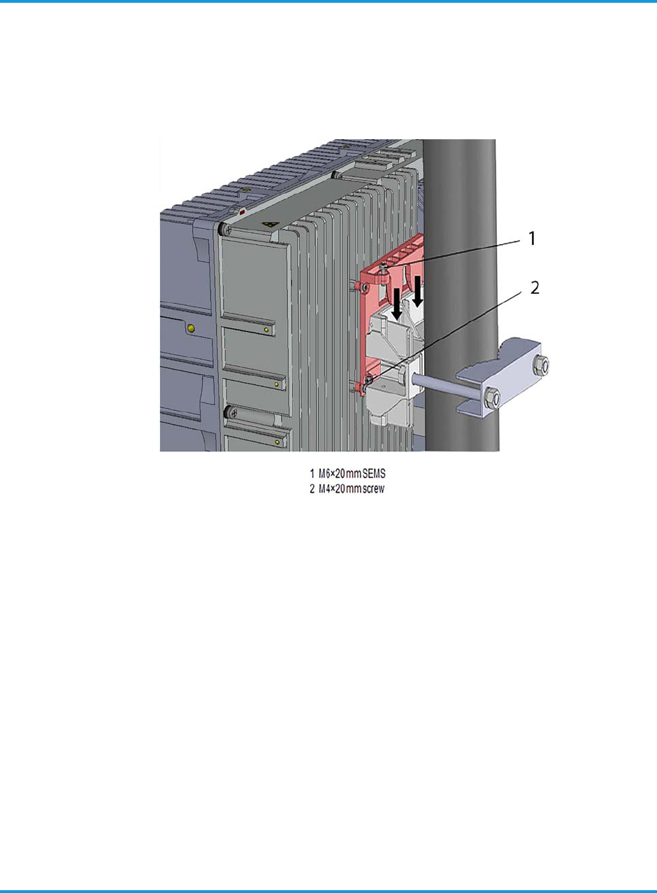
Installing the iRM2249
6-8 iRM2249nn00-1 iRRH Product Description and Installation Guide
Procedure 6-5 To install iRM2249 on the mounting bracket
1. Hang the iRM2249 chassis on the mounting bracket by aligning the mounting plate
tabs on the rear of the chassis to the mounting bracket slots (see Figure 6-6
Aligning mounting plate tabs to mounting bracket on page 6-8).
Figure 6-6 Aligning mounting plate tabs to mounting bracket
2. Lower iRM2249 onto the mounting bracket and align the tapped screw hole on top
of the mounting plate with the tapped screw hole on the mounting bracket.
3. There are two (2) M6 × 20 mm SEMS captive screws on the top of the mounting
plate (See Figure 6-6 Aligning mounting plate tabs to mounting bracket on
page 6-8). Start threading the M6 screws into the mounting bracket screws. Do
NOT fully tighten.
4. Insert two (2) M4 × 20 mm SEMS screws into the screw holes on either side of the
mounting plate.
5. Tighten the M4 screws on the side 13.3 in-lb (1.5 Nm) using a torque wrench.
6. Tighten the M6 screws to 9 in-lb (1 Nm) using a torque wrench.

Installing the iRM2249
iRM2249nn00-1 iRRH Product Description and Installation Guide 6-9
6.5.1 General instructions and clearances upon installing the iRM2249 on the
mounting bracket
Refer to the following points for general instructions and clearances upon
installing the iRM2249 on the mounting bracket:
• The mounting bracket supports mounting on poles between 60mm and
120mm diameter.
• Ensure that the GPS antenna has a clear view of the sky for maximum
signal reception.
• The unit can operate in accordance within stated ambient temperature
range as long as it is mounted correctly (vertically) and air flow across fins
due to natural convection is not impeded. Specific configurations where
this may be an issue can be evaluated and or simulated by Altiostar.
• For mounting clearances on pole or mast refer to Figure 6-7 iRM2249
mounting clearances on pole or mast on page 6-9 and for mounting
clearances on wall refer to Figure 6-8 iRM2249 mounting clearances on
wall on page 6-10.
Figure 6-7 iRM2249 mounting clearances on pole or mast
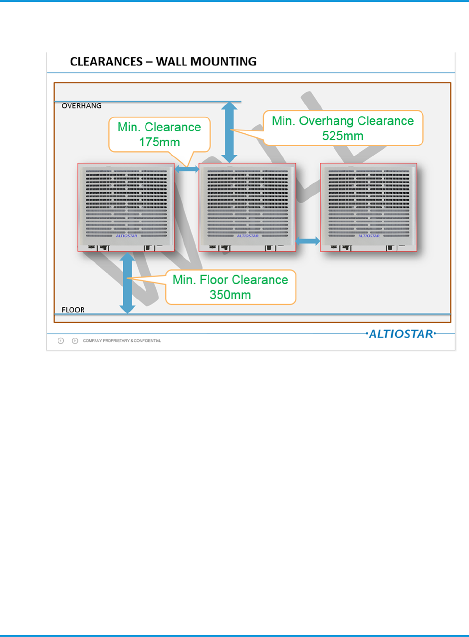
Installing the iRM2249
6-10 iRM2249nn00-1 iRRH Product Description and Installation Guide
Figure 6-8 iRM2249 mounting clearances on wall
6.6 Connecting the grounding cable
This section provides the procedure for properly grounding the iRM2249 to an
earth grounding point. Verify that grounding cable/lug assembly is terminated at
the other end to a tested earth grounding point according to local practice.
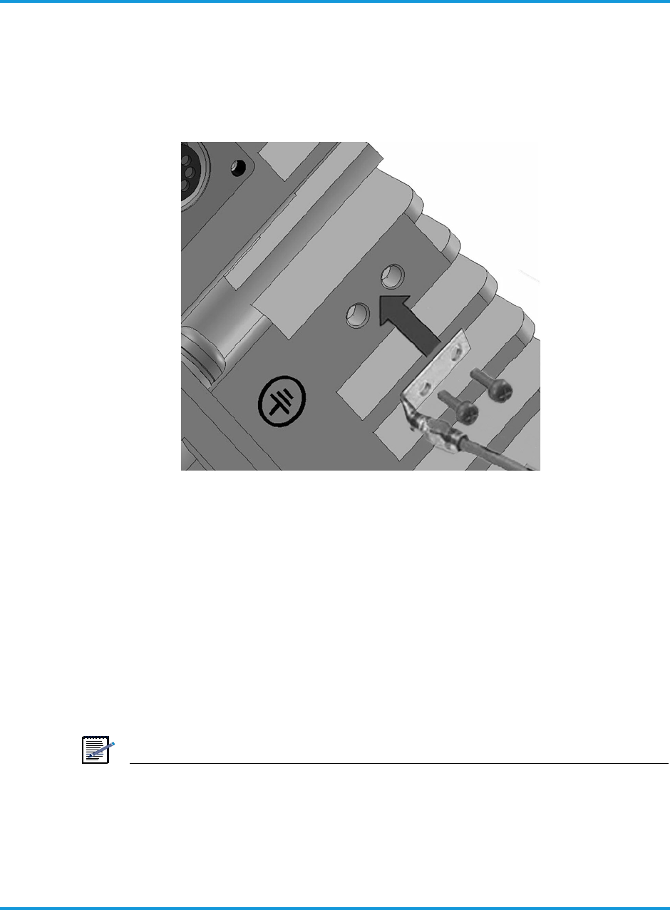
Installing the iRM2249
iRM2249nn00-1 iRRH Product Description and Installation Guide 6-11
Procedure 6-6 To connect grounding cable
1. Fasten the dual-hole grounding lug and cable assembly to the iRM2249 chassis
grounding posts using two (2) M5-0.8 screws and washers (included in the kit).
See Figure 6-9 Connecting the grounding cable on page 6-11.
Figure 6-9 Connecting the grounding cable
2. Tighten the bolts to 2.4 ft-lb (3.2 Nm) using a torque screwdriver.
6.7 Connecting the RET cables
This section provides the procedure for connecting the RET cable to the RET
connector socket.
Procedure 6-7 To connect RET cable
1. Insert RET cable into keyed 8-pin RET socket on iRM2249.
2. Twist the ferrule of the RET connector clockwise until it audibly ‘clicks’ into the
locked position.
NOTE
The RET connection must be waterproofed using a self-fusing tape made for that
purpose. A recommended method of wrapping the connections is provided in
section 6.12.

Installing the iRM2249
6-12 iRM2249nn00-1 iRRH Product Description and Installation Guide
6.8 Connecting the GigE optical fronthaul cables
This section provides the procedure for connecting the GigE optical fronthaul cable
to the FH1 or FH2 SFP connector sockets. A set of detailed assembly instructions
are provided with each Rosenberger Fiber Enclosure. The instructions detail the
assembly of the enclosure over duplex fiber-optic cables.
Procedure 6-8 To connect GigE optical fronthaul cables
1. Remove the captive dust cover of the FH1 fiber optic cable entry port.
2. Remove the four (4) dust plugs on each of the duplex fiber ends and retain for
future use.
3. Insert the duplex into the SFP module recessed inside the FH1 bulkhead
connector until an audible ‘click’ is heard indicting the fiber is locked into the
module.
4. Store any slack of the fiber-optic cable inside the Rosenberger RFE plug to clear if
from getting pinched in the process of connecting the RFE plug to the bulkhead
connector.
5. Align the rails on the side of the Rosenberger RFE plug and push firmly until an
audible ‘click’ is heard indicating the RFE plug is locked into the bulkhead
connector completing the weatherproof seal.
6. If required, repeat step 1 through step 5 for the FH2 fiber optic cable entry port if
two duplex fiber optic cables are used to daisy-chain or sidehaul to another
iRM2249.
NOTE
The fronthaul Ethernet connections must be waterproofed using a self-fusing
tape made for that purpose. Refer to Required tools on page 4-1. Refer to the
recommended taping procedure in Section 6.12. The application of the tape may
vary by Installer local practice.
6.9 Connecting the RF cables
This section provides the procedure for connecting the 4.3-10 connectorized RF
cables to the iRM2249 iRRH.
Procedure 6-9 To connect the RF cables
1. Remove the dust covers from the ANT1 RF connector located on the bottom of the
iRRH and retain for future use.
2. Screw the 4.3-10 RF cable coupling nut onto the ANT1 4.3-10 cable connector.
3. Secure the connection by torquing the coupling nut to 44.25 in-lb (5 Nm).
4. Repeat for ANT2 connector.

Installing the iRM2249
iRM2249nn00-1 iRRH Product Description and Installation Guide 6-13
6.10 Connecting the alarms cable
This section provides the procedure for connecting the alarms cable, terminated at
the macro iRRH with a Lumberg 0322 12 circular 12-contacts female type DIN
connector, to the iRM2249 iRRH.
Procedure 6-10 To connect the alarms cable
1. Remove the captive dust cover from the ALARMS connector located on the side of
the macro iRRH.
2. Screw the DIN connector coupling nut onto the ALARMS connector.
3. Secure the connection by torquing the coupling nut hand tight.
NOTE
The alarms cable must be waterproofed using a self-fusing tape made for that
purpose. Refer to Required tools on page 4-1. Refer to the recommended taping
procedure in Section 6.12. The application of the tape may vary by Installer local
practice.
6.11 Connecting the –48 V DC power cable
This section provides the procedure for connecting the –48 V DC power cable to
the iRM2249 power input connector. Detailed instructions on how to assemble the
power cable to the Rosenberger power connector are provided with the each plug.
Refer to them to install the power connector to the power cable.
NOTE
Power to the –48 V DC power supply cable should be switched off at the breaker
before connecting to the iRM2249 power input connector.
Procedure 6-11 To connect the DC power cable
1. Plug the Rosenberger quick-disconnect power plug into the power input receptacle
labeled POWER located on the bottom of the unit by aligning the two bayonet
lugs into the slots of the coupling nut.
2. Secure the connection by twisting the coupling nut firmly clockwise by hand until
you feel and hear it ‘click’ into the locked position.
NOTE
It is recommended that the –48 V DC power connection be waterproofed using a
self-fusing tape made for that purpose. The application of the tape will vary by
Installer, so local practice will determine how the tape is applied.
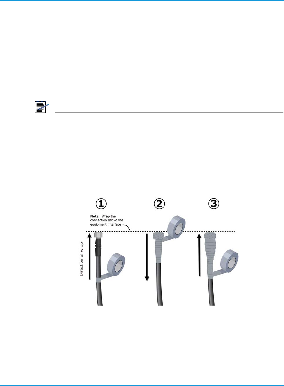
Installing the iRM2249
6-14 iRM2249nn00-1 iRRH Product Description and Installation Guide
6.12 Weatherproofing cable connections
This section provides the procedure for additional weatherproofing of all cable
connections (power, RET, RF, fronthaul, and alarms) to ensure a weather-tight
cable connection is maintained.
Procedure 6-12 To weatherproof cable connections
1. Weatherproof all cable connections by completely wrapping the cable, the
connector on the cable, and the connector threads on the equipment itself with
self-fusing tape (refer to Required tools on page 4-1) as shown in Figure 6-10
Weatherproofing connections using self-fusing tape on page 6-14, or according to
local practice.
NOTE
To ensure a weather-tight connection, be sure to wrap the entire connection
with self-fusing tape. Refer to the recommended taping procedure in Section
6.12.
TIP: It can be hard to remove the self-fusing tape from the connection after it
has weathered over time. To make it easier to remove the self-fusing tape, first
wrap the connection with electrical tape, such as Scotch Super 33+ (or
equivalent) before wrapping the first layer of self-fusing tape.
Figure 6-10 Weatherproofing connections using self-fusing tape

Installing the iRM2249
iRM2249nn00-1 iRRH Product Description and Installation Guide 6-15
6.13 Checking power
This section provides the procedure for verifying power to the iRM2249 is
connected correctly and operating normally.
NOTE
After applying –48 V dc power and verifying that the iRM2249 is functioning
properly, leave power to the unit ON.
Procedure 6-13 To check power to the macro iRRU
1. Switch ON the breaker (or insert the appropriate size and type of fuse) to provide
power to the iRM2249 iRRH.
2. Verify that the iRM2249 powers up as indicated by the LEDs on the side of the
iRM2249 lighting in the boot sequence provided in Table 3-6 LED indicators boot-
up sequence on page 3 - 18.
3. Leave power to the iRM2249 iRRH ON.

Installing the iRM2249
6-16 iRM2249nn00-1 iRRH Product Description and Installation Guide

Terms, Acronyms and Abbreviations
iRM2249nn00-1 iRRH Product Description and Installation Guide 7-1
7 Terms, Acronyms and Abbreviations
Term Description
AWG American Wire Gauge
AWS Advanced Wireless Services
BBU Baseband Unit
BOM Bill of Materials
CBN Common Bonding Network
CFR Code of federal regulations
C-RAN Cloud-Radio Access Network
DIN Digital Input
EIPS Electronics Industry Pallet Specification
EMS Enterprise Management System
EN Engineering Note
FO Fiber Optic
FTTA Fiber-To-The-Antenna
GigE Gigabit Ethernet
GPS Global Positioning System
iBBU intelligent Baseband Unit
IEC International Electrical Code
iRRH intelligent Remote Radio Head
LED Light Emitting Diode
NA Not Applicable
NC No Connection

Terms, Acronyms and Abbreviations
7-2 iRM2249nn00-1 iRRH Product Description and Installation Guide
RET Remote Antenna Tilt
RF Radio Frequency
RFE Rosenberger Fiber Enclosure
RX Receive
SEMS Screw and Washer Assemblies
SS Stainless Steel
TX Transmit
vBBU virtual Baseband Unit
v DC or V dc Voltage direct current
Term Description
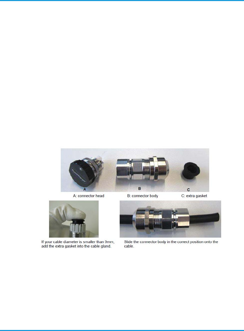
Assembly instructions for 2-pin power connector and cable
iRM2249nn00-1 iRRH Product Description and Installation Guide A-1
Appendix A
Assembly instructions
1 Assembly instructions for 2-pin power connector and
cable
For assembly instructions of the Rosenberger 2-pin power connector, please refer to
Figure A-1 Rosenberger 2-pin power connector and cable on page A-1 through Figure
A-3 Connecting the cable with the connector on page A-3.
Figure A-1 Rosenberger 2-pin power connector and cable
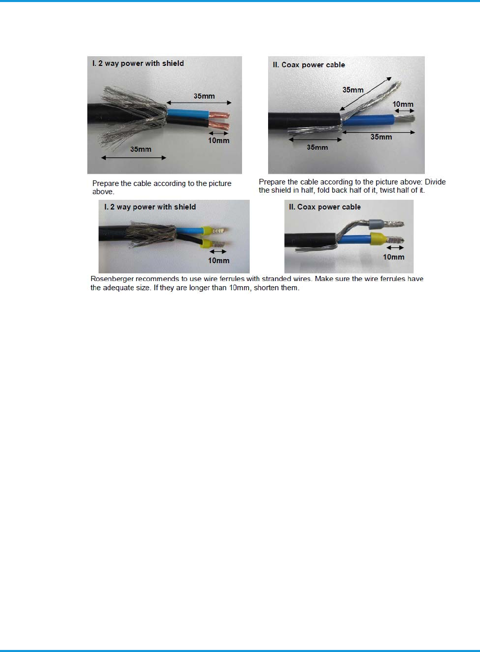
Assembly instructions for 2-pin power connector and cable
A-2 iRM2249nn00-1 iRRH Product Description and Installation Guide
Figure A-2 Preparing the cable
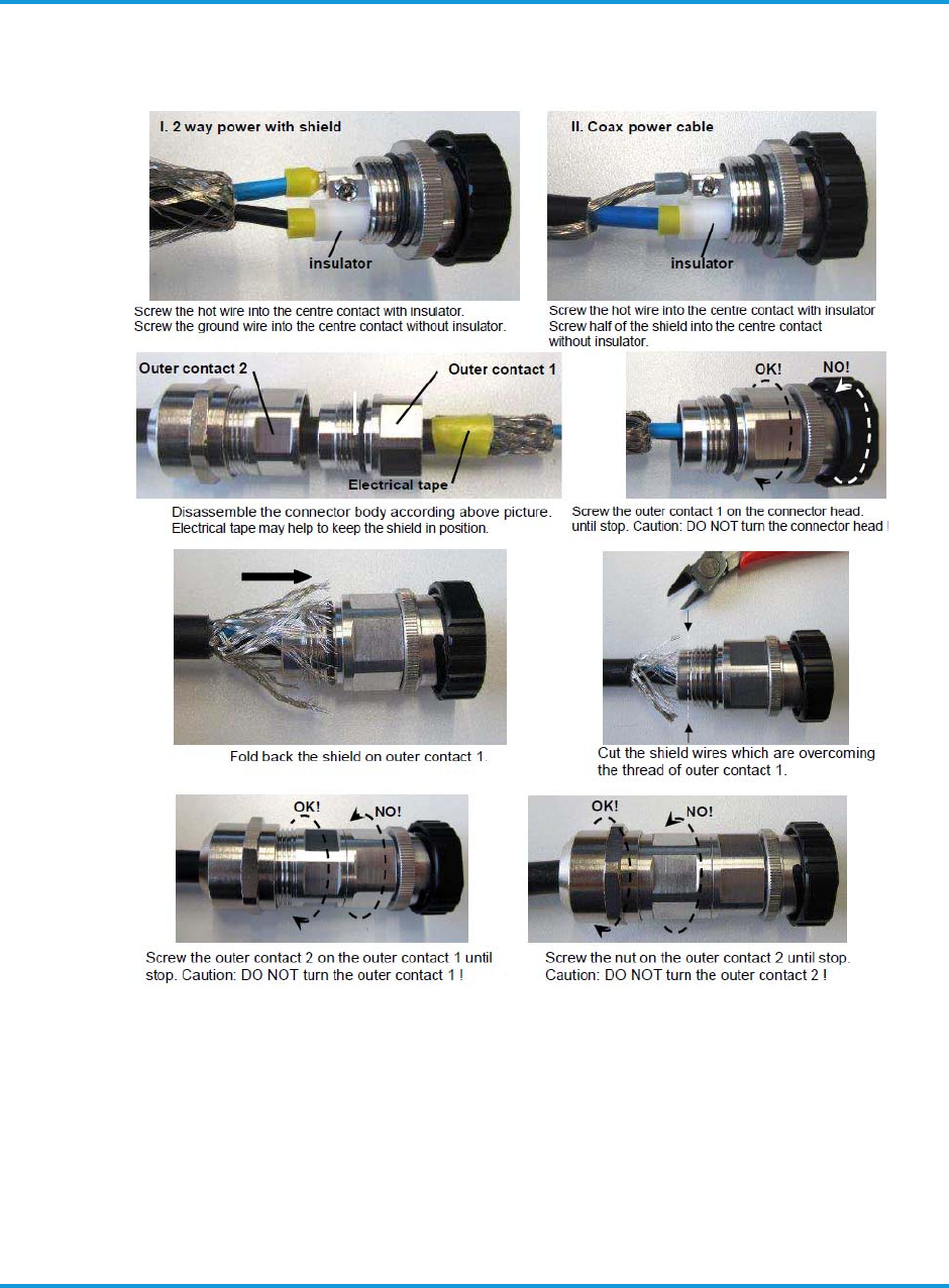
Assembly instructions for 2-pin power connector and cable
iRM2249nn00-1 iRRH Product Description and Installation Guide A-3
Figure A-3 Connecting the cable with the connector

Assembly instructions for Rosenberger Fiber Enclosure
A-4 iRM2249nn00-1 iRRH Product Description and Installation Guide
2 Assembly instructions for Rosenberger Fiber Enclosure
For assembly instructions of the Rosenberger Fiber Enclosure, please refer to Figure
A-4 Rosenberger Fiber Enclosure exploded view on page A-4 and Figure A-5
Rosenberger Fiber Enclosure assembly instructions on page A-4.
Figure A-4 Rosenberger Fiber Enclosure exploded view
Figure A-5 Rosenberger Fiber Enclosure assembly instructions
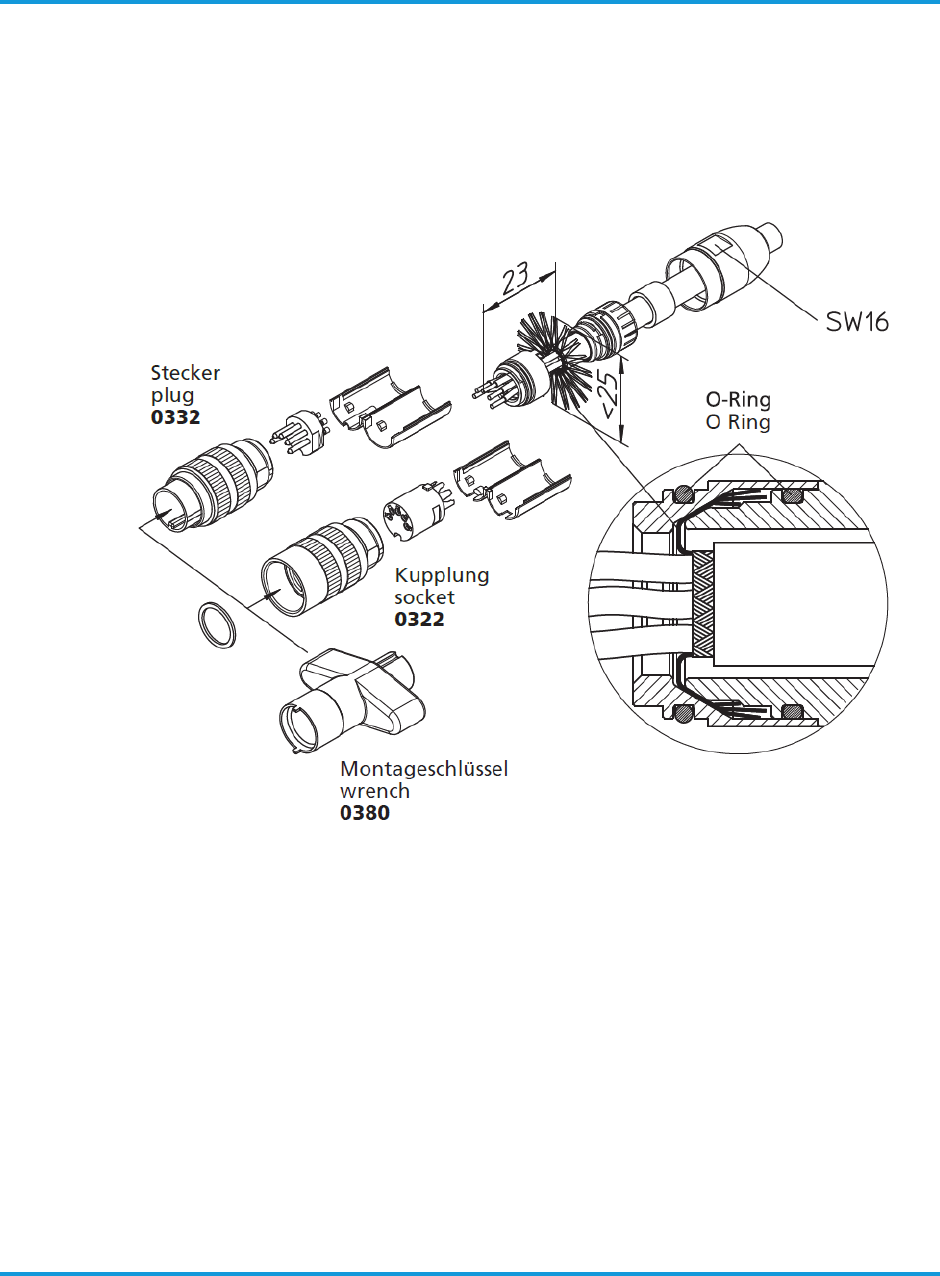
Assembly instructions for circular DIN female connector and cable
iRM2249nn00-1 iRRH Product Description and Installation Guide A-5
3 Assembly instructions for circular DIN female connector
and cable
For assembly instructions of the circular DIN female connector and alarms cable, refer
to Figure A-6 Alarms connector and cable assembly instructions on page A-5.
Figure A-6 Alarms connector and cable assembly instructions
For assembling the Lumberg 0322 12 female connector, the WRENCH (PN: 0380)
shown in Figure A-6 Alarms connector and cable assembly instructions on page A-5,
should be procured by the operator.

Assembly instructions for circular DIN female connector and cable
A-6 iRM2249nn00-1 iRRH Product Description and Installation Guide


iRM2249nn00-1 iRRH Product Description and Installation Guide
Issue 1
240-00-0057
Copyright © 2018 Altiostar Networks, Inc.