Alvarion Technologies AAU-10 WLL System User Manual su2
Alvarion Ltd. WLL System su2
Contents
- 1. 36 pages
- 2. 31 pages
36 pages
Breeze ACCESS
Subscriber Unit
SU-A-D/DV - 2.4-110/220 Series
SU-O-D/DV - 2.4-110/220 Series
Installation
Manual
Revision B.1
August, 1999
Cat. No. 213059

Front Matter Subscriber Unit Installation Guide
II BreezeCOM
© 1999 by BreezeCOM Ltd. All rights reserved.
No part of this publication may be reproduced in any material form without the written permission of
the copyright owner.
Trade Names
BreezeACCESS, BreezeNET, BreezeLINK, BreezeVIEW and WIX are trade names of BreezeCOM Ltd. Other
brand and product names are registered trademarks or trademarks of their respective companies.
Statement of Conditions
The information contained in this manual is subject to change without notice. BreezeCOM shall not be liable for
errors contained herein or for incidental or consequential damages in connection with the furnishing, performance, or
use of this manual or equipment supplied with it.
Warranty
In the following warranty text, “the Company” shall mean:
• BreezeCOM Inc., for products located in the USA.
• BreezeCOM Ltd., for products located outside the USA.
This Breeze ACCESS product is warranted against defects in material and workmanship for a period of one year
from date of purchase. During this warranty period the Company will, at its option, either repair or replace products
that prove to be defective.
For warranty service or repair, the product must be returned to a service facility designated by the Company.
Authorization to return products must be obtained prior to shipment. The buyer shall pay all shipping charges to the
Company and the Company shall pay shipping charges to return the product to the buyer within the USA.
The Company warrants that the firmware designed by it for use with the unit will execute its programming
instructions when properly installed on the unit. The Company does not warrant that the operation of the unit or
firmware will be uninterrupted or error-free.
Limitation of Warranty
The foregoing warranty shall not apply to defects resulting from improper or inadequate maintenance by the buyer,
buyer supplied interfacing, unauthorized modification or misuse, operation outside of the environmental specifications
for the product, or improper site preparation or maintenance. No other warranty is expressed or implied. The
Company specifically disclaims any implied merchantable and fitness warranties for any particular purpose.
Information to User
Any changes or modifications of equipment not expressly approved by the manufacturer could void the user’s
authority to operate the equipment.

Subscriber Unit Installation Guide Front Matter
BreezeCOM III
Safety Considerations
For the following safety considerations, “Instrument” means the Breeze-Access Subscriber Unit
components and its cables.
Caution
To avoid shock, do not perform any servicing unless you are qualified to do so.
Grounding
Before connecting the instrument to the power line, verify that a suitable power cord is being used
(the protective earth terminal of this instrument must be connected to the protective conductor of the
power cord). The mains plug shall only be inserted in a socket outlet provided with a protective earth
contact. If an extension cord (power cable) is used make sure it has a protective conductor
(grounding).
Line Voltage
Before connecting this instrument to the power line, make sure that the voltage of the power source
matches the requirements of the instrument:
• 207-253 VAC for SU-A/O 2.4-220
• 100-120 VAC for SU-A/O 2.4-110
Radio
The instrument transmits radio energy during normal operation. To avoid possible harmful exposure
to this energy, do not stand or work for extended periods of time in front of its antenna. The long-
term characteristics or the possible physiological effects of Radio Frequency Electromagnetic fields
have not been yet fully investigated.
Antenna Installation and Grounding
Be sure that the Outdoor unit, the antenna and the supporting structure are properly installed to
eliminate any physical hazard to either people or property. Verify that the antenna mast is grounded
so as to provide protection against voltage surges and static charges. Make sure that the installation
of the antenna and cable is performed in accordance with all relevant national and local building and
safety codes.
FCC Notice
This equipment has been tested and found to comply with the limits for a Class B digital device,
pursuant to part 15 of the FCC Rules. These limits are designed to provide reasonable protection
against harmful interference in a residential installation. This equipment generates, uses and can

Front Matter Subscriber Unit Installation Guide
IV BreezeCOM
radiate radio frequency energy and, if not installed and used in accordance with the instructions, may
cause harmful interference to radio communications. However, there is no guarantee that
interference will not occur in a particular installation. If this equipment does cause harmful
interference to radio or television reception, which can be determined by turning the equipment off
and on, the user is encouraged to try to correct the interference by one or more of the following
measures:
-Reorient or relocate the receiving antenna.
-Increase the separation between the equipment and receiver.
-Connect the equipment into an outlet on a circuit different from that to which the receiver is
connected.
-Consult the dealer or an experienced radio/TV technician for help.
Changes or modifications to this equipment not expressly approved by the party responsible for
compliance could void the user’s authority to operate the equipment.

Subscriber Unit Installation Guide Table of Contents
BreezeCOM i
TABLE OF CONTENTS
1. System Description......................................................................................................... 2
2. Packing List................................................................................................................... 4
2.1 Other Optional Items Available from BreezeCOM ....................................................... 4
2.2 Other Required Items................................................................................................ 5
3. Installation Guidelines ..................................................................................................... 6
3.1 Installation Overview ................................................................................................ 8
4. Installing the Outdoor Unit - SU-O Series ........................................................................10
4.1 Pole Mounting.........................................................................................................10
4.2 Wall Mounting the Outdoor Unit ...............................................................................11
4.3 Mounting the Antenna..............................................................................................11
5. Installing the Outdoor Unit - SU-A Series ........................................................................12
5.1 Connecting the Baseband, Antenna (SU-O) and Ground Cables...................................12
6. Installing the Indoor Unit................................................................................................13
7. Aligning the Antenna......................................................................................................15
7.1 Aligning the Antenna Using a DVM ...........................................................................16
7.2 Aligning the Antenna Using the Site Survey Menu ......................................................16

Table of Contents Subscriber Unit Installation Guide
ii BreezeCOM
8. Configuring System Parameters ......................................................................................17
8.1 Setup for PC Terminal Emulation Program................................................................18
8.2 Parameters..............................................................................................................18
8.3 IP, Subnet Mask and Default Gateway Address Configuration.....................................19
8.4 ESSID Configuration ...............................................................................................20
8.5 Max. Data Rate Configuration...................................................................................21
8.6 Change Access Rights and Reset Unit........................................................................22
8.7 Voice Port Setup .....................................................................................................22
9. Initial Operation.............................................................................................................23
10. Specifications ..............................................................................................................24
Appendix A. Preparing the Indoor Unit to Outdoor Unit Baseband Cable ...............................27

Subscriber Unit Installation Guide Table of Figures
BreezeCOM iii
Table of Figures
Figure 1. System Diagram.................................................................................................. 3
Figure 2. General Installation Scheme - SU-A Pole Mounting................................................ 9
Figure 3. Pole Mounting Installation...................................................................................11
Figure 4. Outdoor Unit Bottom Connection Panel ...............................................................12
Figure 5. Outdoor Unit (SU-O) Top Connection Panel ........................................................12
Figure 6. Wall Mounting the Indoor Unit ............................................................................13
Figure 7. Indoor Unit Rear Panel.......................................................................................14
Figure 8. Indoor Unit Front Panel......................................................................................15
Figure 9. Site Survey Menu...............................................................................................17
Figure 10. Breeze Access Monitor Main Menu....................................................................19
Figure 11. System Configuration Menu ..............................................................................19
Figure 12. IP and SNMP Parameters .................................................................................20
Figure 13. Wireless LAN Parameters Menu........................................................................21
Figure 14. Outdoor Unit LEDs ..........................................................................................23
Figure 15. Assembling the Indoor-Unit-to-Outdoor Unit Baseband Cable...............................27
Figure 16. Bulgin to 9-Pin D-Type Pin Assignments............................................................28

BreezeCOM 1
About this Manual
This manual contains the following information:
⇒ System Description
⇒ Packing List
⇒ Installation Guidelines
⇒ Installing the Outdoor Unit
⇒ Installing the Indoor Unit
⇒ Setting Basic System Configuration Parameters
⇒ Specifications
⇒ Preparing the Indoor-to-Outdoor Baseband Cable

System Description Subscriber Unit Installation Guide
2BreezeCOM
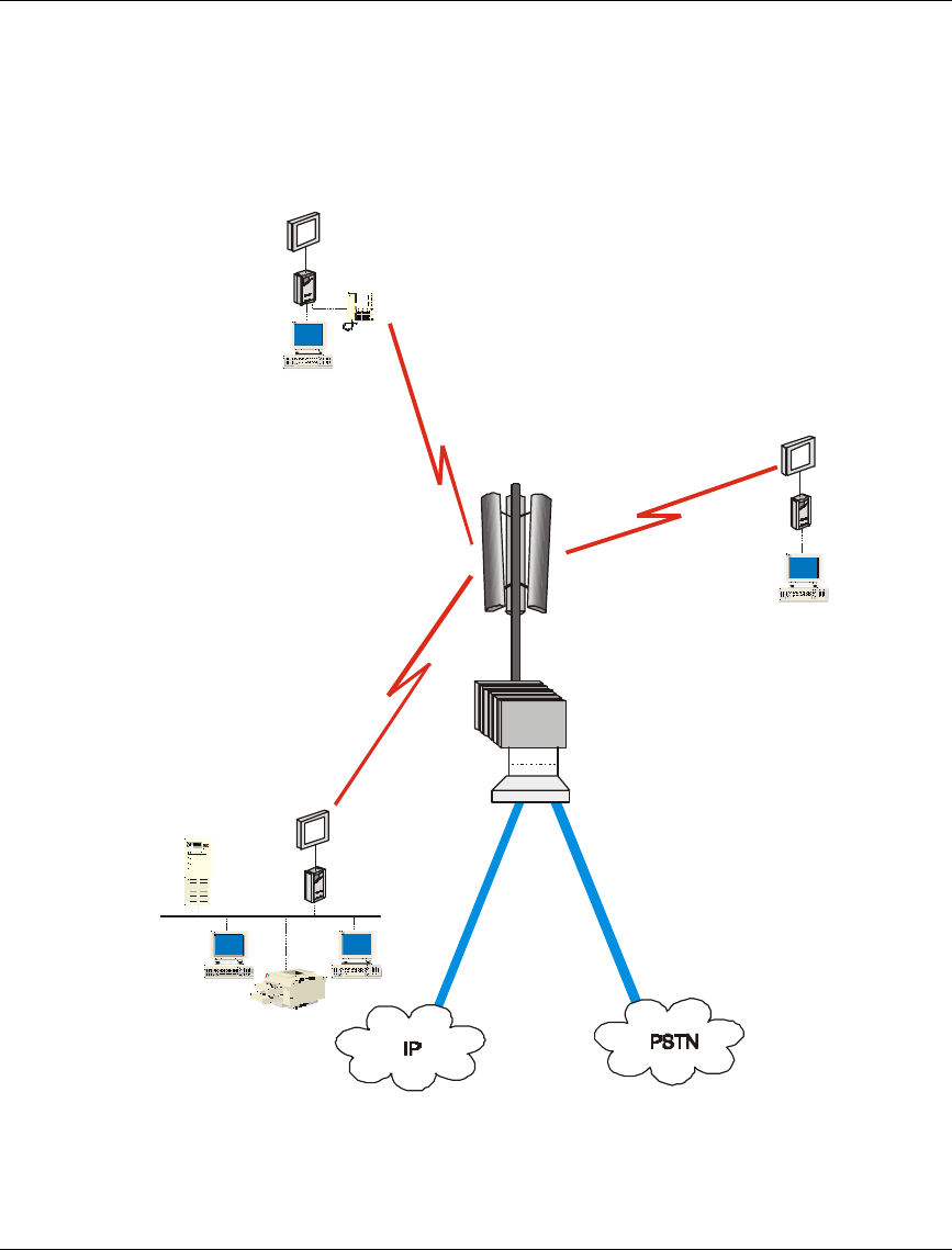
1. System Description
The BreezeACCESS IP Broadband Wireless Local Loop (WLL) system is a high-
performance wireless access system. It allows ISPs and service providers to offer
their subscribers high-speed wireless IP connectivity services. BreezACCESS
employs wireless packet data switching technology, significantly more appropriate
for IP-based services than older switching technology, and supports Voice over IP
(VoIP) based on the H.323 protocol.
The BreezeACCESS 2.4 line of products use Frequency Hopping Spread
Spectrum radios and operate in the 2.4 GHz ISM band allowing for license-free
installation in most countries.
The difference between the SU-A-D/DV series and the SU-O-D/DV series is in the
structure of the Outdoor unit: the Outdoor unit of the SU-A-D/DV line of products
includes an integrated antenna, while the Outdoor unit of the SU-O-D/DV line of
products does not include an antenna.
The Indoor units of both the SU-A-D/DV and the SU-O-D/DV series provide
interfaces to user's equipment. In addition, the Indoor unit provides 48 VDC to the
Outdoor unit.
The SU-A-D/DV and the SU-O-D/DV lines of products, through the Ethernet port,
provide all the functionality required to connect workstation computers and other
Ethernet equipment at the subscriber premises to the network. SU-A-DV and
SU-O-DV lines of products provide the same data functionality, plus a telephone
interfaces supporting regular telephones.
The SU-A/O-D/DV-2.4 110 lines of products operate with main voltage of 110
VAC, while the SU-A/O-D/DV-2.4 220 lines of products operate with main voltage
of 220 VAC.
The SU-A/O-D 2.4-110/220 series includes the following products:
• SU-A/O-1D-2.4-110/220: supports a single Ethernet workstation/PC
• SU-A/O-8D-2.4-110/220: supports up to 8 Ethernet workstations/PCs
• SU-A/O-BD-2.4-110/220: supports a LAN (a bridge functionality)
Subscriber Unit Installation Guide System Description
BreezeCOM 3
The SU-A/O-DV 2.4-110/220 series includes the following product:
• SU-A/O-1D1V-2.4-110/220: supports a single Ethernet workstation and a
regular telephone interface
SU-1D
SU-BD
AU
Router/
Gateway
SU-1D1V
Figure 1. System Diagram

Packing List Subscriber Unit Installation Guide
4BreezeCOM
2. Packing List
• Indoor unit
• Outdoor unit (includes integrated antenna on SU-A models)
• 110/220 VAC Power Cord (open ended)
• Sun-guard (installed on the rear side of the Outdoor unit)
• Telephone cable (for the SU-A/O DV series only)
2.1 Other Optional Items Available from BreezeCOM
• Technician cable
• U-bolts size A kit for pole mounting (up to 2" pole)
• U-bolts size B kit for pole mounting (up to 3" pole)
• Wall mounting kit
• Sun-guard (optional for front side, SU-O only)
• Baseband cable (available in different lengths)
• A set of connectors for the Baseband cable (when not using the cables
available from BreezeCOM. Refer to Appendix A for instructions on how to
build the cable.)

Subscriber Unit Installation Guide Packing List
BreezeCOM 5
2.2 Other Required Items
In addition to the items supplied by BreezeCOM, the following items must be
available for the installation.
• Antenna for SU-O series line of products; refer to the Specifications on
page 24 for information regarding the radio unit
• An RF cable connecting the antenna to the Outdoor unit (SU-O series only)
• Power mains cable termination plug per country of installation
• U-bolts or metal bands for pole mounting (if not using the optional U-bolts
kit available from BreezeCOM)
• Ground cables with an appropriate terminal
• Ethernet cable (straight)

Installation Guidelines Subscriber Unit Installation Guide
6BreezeCOM
3. Installation Guidelines
This manual covers basic installation procedures. All the parameters not mentioned
here can be configured remotely from the Access unit (refer to the Administration
Manual for further information).
Follow the instructions in the appropriate column according to the products that
you have purchased.
SU-O Series SU-A Series
• Select an appropriate location for the
Outdoor unit and the antenna (not supplied
by BreezeCOM). The antenna should be
mounted on a pole and should be installed
where a direct line of sight with the Access
Unit/Base Station antenna can be
established. The antenna should be directed
towards the Access Unit/Base Station and
placed where it shall be convenient to align
it to optimally aim towards the Access
Unit/Base Station.
• The Outdoor unit can be pole- or wall-
mounted. Its location should be selected to
allow easy access to the unit for installation
and testing. The antenna and Outdoor unit
should be installed near each other.
• The Outdoor unit is designed for operation
under outdoors environmental conditions.
However, it is recommended to try to install
it in a place where its exposure to direct
sunlight will be minimal.
• The unit is designed to withstand rain and
humidity. However, it is not designed to
• Select an appropriate location for the
Outdoor unit. The Outdoor unit should be
mounted on a pole and should be installed
where a direct line of sight with the
Access Unit/Base Station antenna can be
established. The front side of the unit
should be directed towards the Access
Unit/Base Station and placed where it
shall be convenient to align it to optimally
aim towards the Access Unit/Base
Station.
• The Outdoor unit can be pole- or wall-
mounted. Its location should be selected
to allow easy access to the unit for
installation and testing.
• The Outdoor unit is designed for
operation under outdoors environmental
conditions. However, it is recommended
to try to install it in a place where its
exposure to direct sunlight will be
minimal.

Subscriber Unit Installation Guide Installation Guidelines
BreezeCOM 7
SU-O Series SU-A Series
withstand immersion in water and it should
not be installed in a place where large
quantities of water can accumulate.
• The maximum length of the Baseband
cable, between the Indoor and the Outdoor
unit, should not exceed 30 meters.
• Select an appropriate location for the Indoor
unit. The Indoor unit should be installed in a
place that is as close as possible to the exit
point of the cable connecting it to the
Outdoor unit. The selection of location of
the Indoor unit should also take into account
the need to connect it to a power outlet and
to the user’s PC (or LAN).
• The unit is designed to withstand rain and
humidity. However, it is not designed to
withstand immersion in water and it
should not be installed in a place where
large quantities of water can accumulate.
• The maximum length of the Baseband
cable, between the Indoor and the
Outdoor unit, should not exceed 30
meters.
• Select an appropriate location for the
Indoor unit. The Indoor unit should be
installed in a place that is as close as
possible to the exit point of the cable
connecting it to the Outdoor unit. The
selection of location of the Indoor unit
should also take into account the need to
connect it to a power outlet and to the
user’s PC (or LAN).
Note: The SU-O Outdoor unit comes with a sun-guard mounted on its rear
side. This accessory can be removed by unscrewing the attaching screws,
and can be installed on the front side if necessary. A second, optional
sun-guard can be ordered for assembly on the front cover. The second
sun-guard is recommended for installations where both the front and the
back of the Outdoor unit may be exposed to direct sunlight. Contact your
BreezeCOM representative for a parts catalog with the accessories that
you can order.

Installation Guidelines Subscriber Unit Installation Guide
8BreezeCOM
3.1 Installation Overview
Note: It is highly recommended to complete configuration of the system
parameters in a lab prior to the installation. Refer to page 17 for
instructions on these settings.
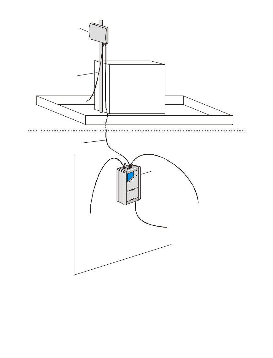
The typical installation scheme is depicted in Figure 2. The installation process
should follow these general steps:
1. Mount the Outdoor unit. If you are installing an SU-O series, mount an
external antenna (not supplied by BreezeCOM). Connect the Outdoor unit to
the antenna (SU-O series only). Connect the Baseband and ground cables to
the Outdoor unit.
2. Mount the Indoor unit. Connect the Baseband cable (from the Outdoor unit).
Connect the Indoor unit to the AC mains via the power cable.
3. Verify optimal antenna positioning.
4. Verify connectivity to the Base Station.
5. Connect the Indoor unit Ethernet connector to the user’s network/PC using an
Ethernet Cable (a straight cable for connecting SU-A/O 1D or SU-A/O 1D1V
to a PC, or for connecting SU-A/O BD or SU-A/O 8D to a hub).
6. Connect the telephone cord to the voice port and the POTS (DV products).
7. Connect an ASCII terminal to the MON port of the Outdoor unit(s) via the
technician cable and configure basic system parameters.
Note: The Indoor unit should be connected to the power source only after the
Outdoor unit have been connected to it.
Subscriber Unit Installation Guide Installation Guidelines
BreezeCOM 9
OUTDOOR
INDOOR
Indoor Unit
To Monitor/DVM
To Mains
To Telephone (DV Series)
To PC/LAN
To Outdoor Unit
Outdoor Unit
Technician cable
Figure 2. General Installation Scheme - SU-A Pole Mounting
Baseband cable

Installing the Outdoor Unit - SU-O Series Subscriber Unit Installation Guide
10 BreezeCOM
4. Installing the Outdoor Unit - SU-O Series
Note: When mounting the Outdoor unit, be sure to mount it with the Antenna
connectors facing upwards.
The Outdoor unit can be mounted in either of the following configurations:
• Pole mounted
• Wall mounted
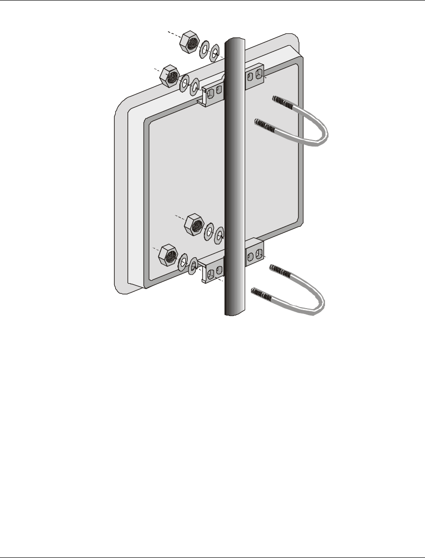
4.1 Pole Mounting
Choose a location where the unit's exposure to direct sunlight is minimal. Avoid
placing it in locations where water might accumulate. If necessary, install the sun-
guard plates on the panels where exposure to sunlight is expected.
The installation holes on the rear side of the Outdoor unit (see Figure 3) can be
used to pole mount the unit using one of the following options:
• U-bolt - size A (inside installation holes, up to 2" pole)
• U-bolt - size B (outside installation holes, up to 3" pole)
• Metal bands
Subscriber Unit Installation Guide Installing the Outdoor Unit - SU-O Series
BreezeCOM 11
Figure 3. Pole Mounting Installation
4.2 Wall Mounting the Outdoor Unit
See the instructions included with the wall mounting kit.
4.3 Mounting the Antenna
Secure brackets to the antenna using screws, lock washers and nuts as appropriate.
Mount the antenna on a pole and secure it using metal bands or U-bolts. Do not
tighten the metal bands or U-bolts, in order to enable rotation of the antenna over
the horizontal plane. The front of the antenna should be directed towards the Base
Station/Access Unit. Use Vertical Polarization.
Installing the Outdoor Unit - SU-A Series Subscriber Unit Installation Guide
12 BreezeCOM
5. Installing the Outdoor Unit - SU-A Series
Note: All SU-A Outdoor units are supplied with a sun-guard assembled on the
rear panel of the unit.
The SU-A Outdoor unit should be installed on a pole to allow optimal alignment.
Use the installation holes (see Figure 3) to pole mount the unit using one of the
following options:
• U-bolt - size A (inside installation holes, up to 2" pole)
• U-bolt - size B (outside installation holes, up to 3" pole)
• Metal bands
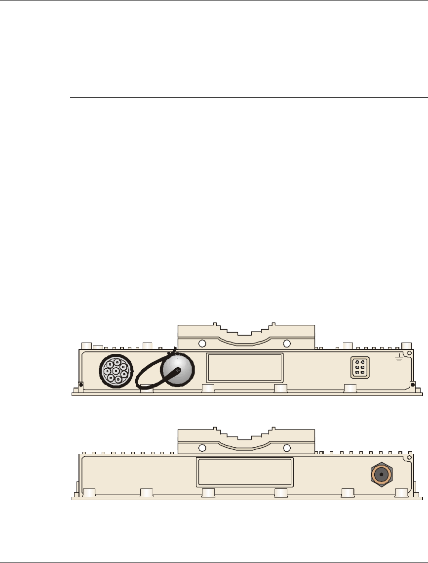
5.1 Connecting the Baseband, Antenna (SU-O) and Ground Cables
The Baseband and Ground cable connectors are located on the bottom panel of the
Outdoor unit, shown in Figure 4. The Antenna connector is located on the top
panel of the SU-O series Outdoor unit, shown in Figure 5.
L
M
H
ETH
WLNK
PWR
INDOOR MON
Figure 4. Outdoor Unit Bottom Connection Panel
ANT. 2
Figure 5. Outdoor Unit (SU-O) Top Connection Panel
Subscriber Unit Installation Guide Installing the Indoor Unit
BreezeCOM 13
1. If you are installing an SU-O series, connect the antenna cable between the
Outdoor unit and the antenna.
2. Connect one end of the ground cable to the Outdoor unit bottom panel and
connect the other end to a good ground connection.
3. Connect the Indoor unit to Outdoor unit Baseband cable, supplied with the
access unit, to the appropriate connector. Appendix A provides instructions on
how to prepare this cable.
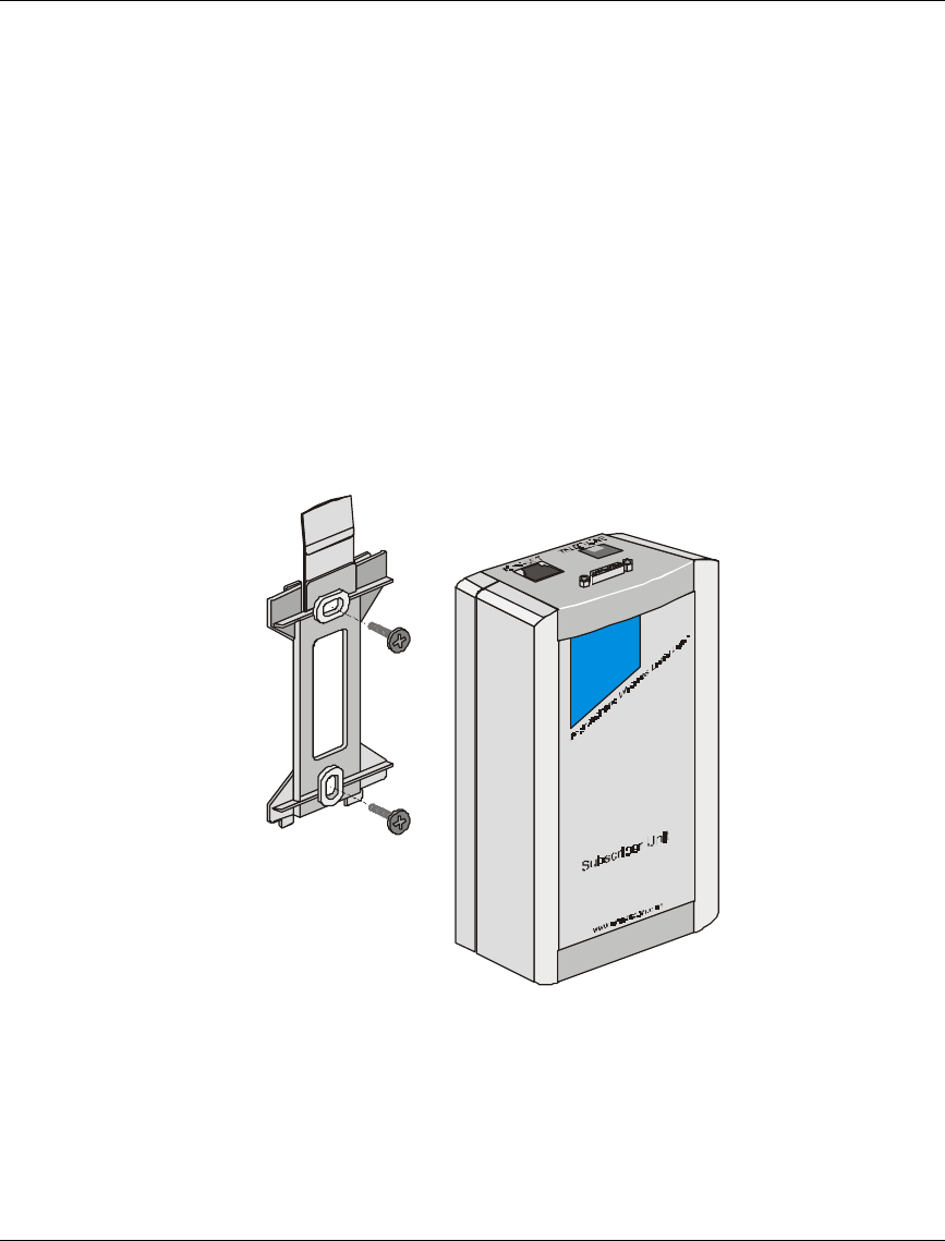
6. Installing the Indoor Unit
1. Remove the wall mounting bracket clipped to the rear of the Indoor unit and
mount the Indoor unit on a wall as shown in Figure 6.
Figure 6. Wall Mounting the Indoor Unit
2. According to specific conditions, route the Outdoor unit to Indoor unit
Baseband cable into the house/office so that it shall conveniently reach the
Indoor unit in such a way as to ensure minimal interference, leaving some
Installing the Indoor Unit Subscriber Unit Installation Guide
14 BreezeCOM
spare. Connect the Baseband cable to the Radio connector, located on the
front panel of the Indoor unit shown in Figure 8.
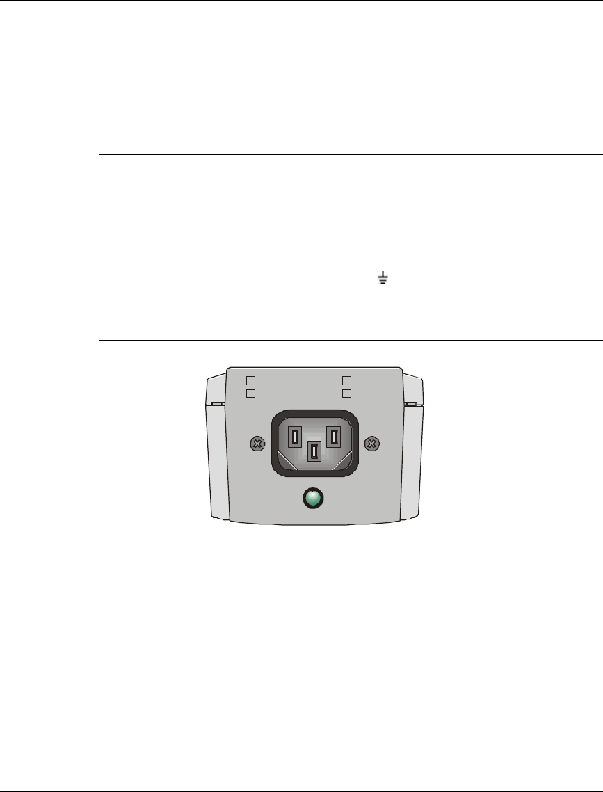
3. Connect the power cord to the unit’s port connector, located on the rear panel
shown in Figure 7. Connect the other end of the power cord to the AC mains.
Note: Prepare the other end of the power cord with a power plug appropriate
to the country in which the unit is being installed. The color codes of the
cable are:
brown phase ~
blue neutral 0
yellow/green grounding
The factory set voltage of the Indoor unit is marked appropriately on the
rear panel of the unit.
POWER
100-120VAC
207-253VAC 250mA
500mA
Figure 7. Indoor Unit Rear Panel
4. Verify that the LED, located on the rear panel, is ON indicating that the 48
VDC is not shorted.
Subscriber Unit Installation Guide Aligning the Antenna
BreezeCOM 15
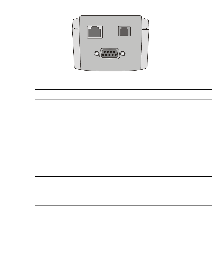
RADIO
10-BASE-T TELEPHONE
Figure 8. Indoor Unit Front Panel
Note: Only units with the DV option have the Telephone port.
5. Connect a PC (SU-A/O 1D or SU-A/O 1D1V) or a hub (SU-A/O 8D or
SU-A/O BD) to the 10-Base T connector, located on the front panel of the
Indoor unit. The cable connection should be straight.
6. Use the telephone cord to connect the Telephone port to the user’s telephone
(units with DV option only).
Note: The length of each of the cables connected to the user's equipment,
together with the length of the Baseband cable, should not exceed 100
meters.
7. Aligning the Antenna
Note: Antenna alignment is possible only after the Access unit you wish to
associate with operates.
To align the antenna, you can either use a DVM or view the Received Signal
Strength Indication (RSSI) on the Monitor.

Aligning the Antenna Subscriber Unit Installation Guide
16 BreezeCOM
7.1 Aligning the Antenna Using a DVM
1. Connect the technician cable to the Monitor port on the bottom panel of the
Outdoor unit.
2. Connect a DVM (Digital Voltmeter) to the two wires in the technician cable.
3. Move the antenna left and/or right until you reach the point of maximum RSSI
reading. RSSI readout range is 1.50 to 3.30 volts (the higher the better). Make
sure that all the time, the front of the antenna faces the general direction of the
Base Station so as not to use the back lobe rather than the front lobe of the
antenna for tuning.
4. For proper operation the RSSI reading should be at least 2 volts. If maximal
reading is lower try to improve it through placing the antenna higher or in a
different location.
Note: The DVM reading might be inaccurate due to possible reception of
energy from other devices transmitting energy in the 2.4GHz ISM band.
When in doubt, verify performance using the Print-Per-Hop Statistics
that is based on measurement of the desired signal only.
7.2 Aligning the Antenna Using the Site Survey Menu
1. To use the Site Survey menu configure the ESSID parameter (refer to
Section 8.4).
2. Connect the terminal to the Outdoor unit using the technician cable.
3. From the main menu type 3 to access the Site Survey menu. Type 3 to access
the Print Per-Hop Statistics selection screen. Type 1 to display RSSI readouts
per frequency. In order to update the screen press Enter twice.

Subscriber Unit Installation Guide Configuring System Parameters
BreezeCOM 17
Site Survey
===========
1 - Traffic Statistics
2 - Wireless Management Statistics
3 - Print Per-Hop Statistics
4 - TCP/IP Statistics
5 - VLAN Statistics
6 - Memory Usage Statistics
7 - Average RSSI Continues Display (SU only !)
8 - MAC Address database
9 - Voice Statistics
A - Call Management Statistics
Figure 9. Site Survey Menu
4. Move the antennas until the maximum received signal strength is attained. As
you align the antennas, you will see that the RSSI (received signal strength
indicator) continually increases until it reaches a certain level after which the
RSSI begins to decrease. This is the maximum attainable RSSI level indicating
optimum receive antenna alignment.
5. For proper operation the RSSI reading should be at least 75 units. When
maximal reading is lower try to improve it through placing the antenna higher
or in a different location.
6. Tighten the U-bolts (or metal band) over the antenna to secure it to the pole.
8. Configuring System Parameters
After completing the installation process for both the Outdoor and Indoor units, as
described in the preceding sections of this manual, proceed with alignment of the
antenna and configuration of the basic system parameters.
For this configuration process, you will need to connect an ASCII terminal with
terminal emulation software (e.g., Procomm or Windows 95 HyperTerminal) to
the MON port of the Outdoor unit(s) via the supplied technician cable.

Configuring System Parameters Subscriber Unit Installation Guide
18 BreezeCOM
8.1 Setup for PC Terminal Emulation Program
Use the following setup for the ASCII terminal connection:
Baud rate 9600
Data bits 8
Stop bits 1
Parity None
Flow Control None
Connector Available Com Port
Note: Optionally, the product can be configured using Telnet over the Ethernet
port, after setting IP address. For further information refer to the
Administration Manual.
8.2 Parameters
The following system parameters must be configured for each specific installation:
• IP Address
• Subnet Mask
• Default Gateway Address
• ESS ID
• Max. Data Rate
At the end of the configuration process access rights setting should be changed to
“Installer”. It is recommended to configure system parameters at the laboratory
prior to the actual installation.
Note: You should select Reset Unit in the Station Control Sub-menu for the
changes to take effect.

Subscriber Unit Installation Guide Configuring System Parameters
BreezeCOM 19
8.3 IP, Subnet Mask and Default Gateway Address Configuration
1. After connecting the ASCII terminal to the Outdoor unit, press Enter to access
the BreezeACCESS Monitor main screen.
BreezeACCESS (SU-A/O)
Official Release Version - 1.3.5
Release Date: Wed Apr 28 16:23:57 1999
BreezeACCESS Monitor
=====================
1 - System Configuration
2 - Advanced Settings
3 - Site Survey
4 - Access Control
BreezeACCESS >>>
Figure 10. Breeze Access Monitor Main Menu
2. Type 1 to access the System Configuration sub-menu.
System Configuration
====================
1 - Station Status
2 - TCP\IP and SNMP Parameters
3 - Wireless LAN Parameters
4 - Bridging
5 - Station Control
BreezeACCESS >>>
Figure 11. System Configuration Menu
3. Type 2 to access the TCP/IP and SNMP Parameters sub-menu.

Configuring System Parameters Subscriber Unit Installation Guide
20 BreezeCOM
IP and SNMP Parameters
======================
1 - IP Address
2 - Subnet Mask
3 - Default Gateway
Address
4 - SNMP Traps
5 - TCP Parameters
S - Display Current Values
Figure 12. IP and SNMP Parameters
4. Type 1 to access the IP Address selection screen. Type in the required IP
Address determined by the system manager. Press Enter to return to the IP
and SNMP Parameters menu.
5. Type 2 to access the Subnet Mask selection screen. Type in the required
Subnet mask.
6. Press Enter to return to IP and SNMP Parameters menu.
7. Type 3 to access the Default Gateway Address selection screen. Type in the
required gateway address. Press Enter to return to IP and SNMP Parameters
menu.
8.4 ESSID Configuration
1. Press Esc to return to the System Configuration menu.
2. Type 3 to access the Wireless LAN Parameters menu.

Subscriber Unit Installation Guide Configuring System Parameters
BreezeCOM 21
Wireless LAN Parameters
=======================
1 - Hopping Sequence (Shift) (AU only)
2 - Hopping Sequence Offset
3 - Hopping Sequence Set
4 - ESS ID
5 - Max. Data Rate
6 - Transmit Diversity
7 - Mobility
8 - Load Sharing
9 - Long Range
A - Prioritized Channels
B - MIR And CIR Parameters
S - Display Current Values
BreezeACCESS >>>
Figure 13. Wireless LAN Parameters Menu
3. Type 4 to access the ESS ID selection screen.
4. Type in the required ESS ID.
8.5 Max. Data Rate Configuration
1. Press any key to return to the Wireless LAN Parameters menu.
2. Type 5 to access the Max. Data Rate selection screen.
a) Select 3 (3Mbps) if the RSSI reading, when using the Site Survey menu, is
higher than 2.5 Volts (93 units).
b) Select 2 (2Mbps) if the RSSI reading, when using the Site Survey menu, is
between 2.2 Volts and 2.5 Volts (83 to 93 units).

Configuring System Parameters Subscriber Unit Installation Guide
22 BreezeCOM
c) Select 1 (1Mbps) if the RSSI reading, when using the Site Survey menu, is
lower than 2.2 Volts (83 units).
8.6 Change Access Rights and Reset Unit
1. After properly configuring all system parameters, the access right should be
changed to USER to prevent users from unauthorized tampering with system
parameters. Press Esc three times to return to the main menu. Type 4 to
access the Access Control menu. Type 1 to access the Change Access Rights
menu. Type 0 to select Installer access rights allowing users only reading the
configured parameters.
2. Press Esc twice to return to main menu. Type 1 to access the System
Configuration menu. Type in 5 to access the Station Control sub-menu. Type
1 to access the Reset Unit sub-menu. Type in 1 to reset the unit so that new
configuration settings are applied.
Note: Should you make any mistake during configuration, or should you
encounter any problem associated with system configuration parameters,
you may configure the unit back to the factory defaults.
Select 2 in the Station Control menu to access the Set Factory Defaults
menu and than Type in 1 to load the default values. Select 1 in the station
control menu to access the Reset Unit, then type 1 so that the unit will be
reset in order for the factory defaults to take effect.
8.7 Voice Port Setup
Note: This setting only applies to DV series units that have a telephone
interface.
The specific configuration sequence varies according to the equipment (gateway
and gatekeeper) that is used by the Service Provider. For further information on
the Voice Port setup refer to the Telephony Application Manual.
Subscriber Unit Installation Guide Initial Operation
BreezeCOM 23
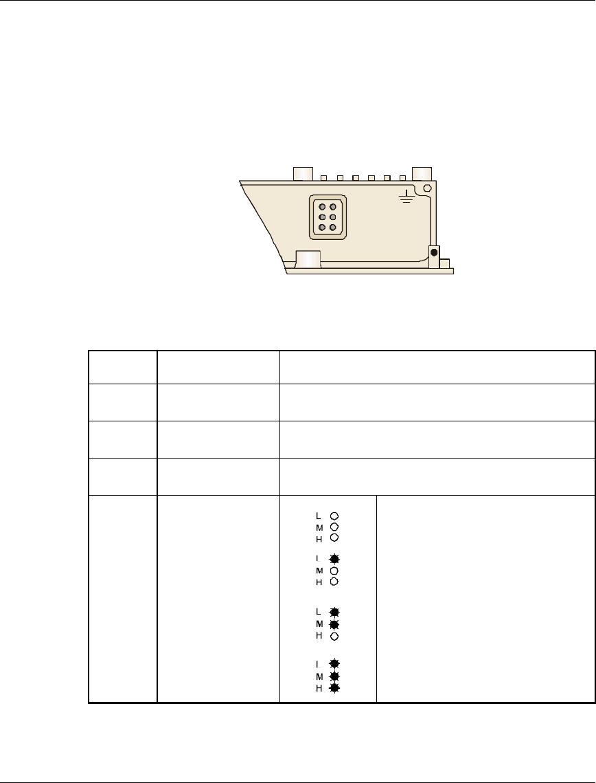
9. Initial Operation
After completing the installation as described above, the system starts operation.
To verify correct operation, view the LED panel located on the bottom panel of
the Outdoor unit, as shown in Figure 14.
L
M
H
ETH
WLNK
PWR
Figure 14. Outdoor Unit LEDs
The following table lists the various LED states.
Name Description Functionality
PWR Power supply On – After successful power up
Off – Power off
WLNK Synchronization Off – No Synchronization
On – Synchronization with Access unit
ETH Ethernet activity Blinking – Reception of data from Ethernet LAN
Off – No reception of data from Ethernet LAN
QLT Quality of
received RF
signal
very low quality reception or not
synchronized with Access Point less than
-81 dBm
low quality reception (usually enabling
1Mbps traffic) from -81 to -77 dBm
medium quality reception (usually enabling
2 Mbps traffic) from -77 to -65 dBm
high quality reception (usually enabling 3
Mbps traffic) greater than -65 dBm
Specifications Subscriber Unit Installation Guide
24 BreezeCOM
10. Specifications
Radio
Frequency 2.4 GHz ISM Band
Operation and Standards FHSS, ETSI, ETS 300 328; FCC Part 15
Operation mode Time Division Duplex
Output Power (SU-O) USA (FCC): 17 dBm, Europe (ETSI): 0dBm
Antenna Gain (SU-A) 16dBi
Transmitted Power (SU-A) FCC: 33dBm EIRP
ETSI: 20dBm EIRP, max.
Sensitivity
(dBm, BER 1E10-6)
1Mbps
2Mbps
3Mbps
-81
-75
-67
Data Rate 3Mbps max
Modulation Multilevel GFSK: 2 (@ 1Mbps), 4 (@ 2Mbps) or 8 (@
3Mbps) FSK
Management
CIR Committed Information rate; Symmetrical/Asymmetrical CIR support
MIR Maximum Information Rate (burst rate) limitations
Class of Service CIR/MIR by customer; Prioritize transport by customer
System
Management SNMP agent, Telnet
Security Authentication based on RC-4
Software Upgradeable (download)
Subscriber Unit Installation Guide Specifications
BreezeCOM 25
Voice Communication (DV series only)
Protocol H.323 Voice over IP compliant
Compression G.723 6.3 Kbps compression, G.729 8Kbps compression, G.711
64Kbps transparent
Echo Cancellation G.165
Interfaces
Outdoor Unit Indoor Unit
RF N Type, male (SU-O)
Ethernet 10Base-T (RJ-45)
Telephone
(DV products) RJ-11 (POTS)
Monitor Mini Sealed connector, 5 pin,
female
Power AC power oulet
Outdoor to Indoor
unit Mini Sealed connector, 8 pin,
male 9-pin D-type, female
Indicators
Outdoor Unit Indoor Unit
Power, Ethernet, Sync, quality Power
Specifications Subscriber Unit Installation Guide
26 BreezeCOM
Electrical
Outdoor Unit Indoor Unit
48 VDC from Indoor Unit 110/220 VAC
Mechanical
Outdoor Unit Indoor Unit
31cm x 31cm x 4.7cm (SU-O)
31cm x 31cm x 9.6cm (SU-A)
15.4cm x 8.4cm x 5.6cm
Environmental
Outdoor Unit Indoor Unit
Operating
Temperature -400C to 500C00C to 400C
Operating Humidity Weather protected 5%-95% non condensing
Subscriber Unit Installation Guide Apeendix A
BreezeCOM 27
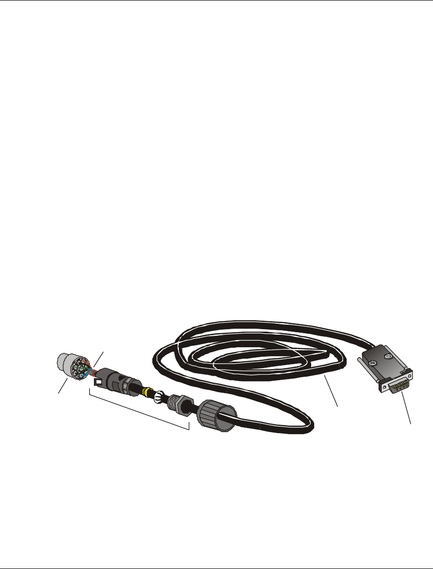
Appendix A. Preparing the Indoor Unit to Outdoor Unit
Baseband Cable
To assist in assembling the Indoor-Unit-to-Outdoor Unit Baseboard cable, use the
following tools.
1. For Bulgin Mini Sealed connector:
• Bulgin Contact Insertion Tool (P/N SA3150)
• Bulgin Crimping Tool (SA 2800)
For further information, refer to Bulgin's Internet site at www.bulgin.co.uk.
2. For D-Type 9-pin connector:
• Amphenol hand crimp tool 17 D 440 SP
• Amphenol contact insertion and removal tool 17 D 438 SP
Flex Mounting Body
BULGIN
PX0800
Contact Carrier
M/F BULGIN
Cat. No. 12735
Desc. Contacts
M/F BULGIN
Cat. No. SA3149
Male
D-Type
9-pin
4x2x24# Cat.5
Patch Cable
For Outdoor Use
Figure 15. Assembling the Indoor-Unit-to-Outdoor Unit Baseband Cable
Appendix A Subscriber Unit Installation Guide
28 BreezeCOM
1
2
3
4
5
6
7
8
9
B
U
L
G
I
N
ETH_TX-
ETH_TX-
ETH_TX+
ETH_TX+
N.C.
DC_0V
DC_0V
DC_-48V
DC_-48V
ETH_RX-
ETH_RX-
ETH_RX+
ETH_RX+
TEL_TIP
TEL_TIP
TEL_RING
TEL_RING
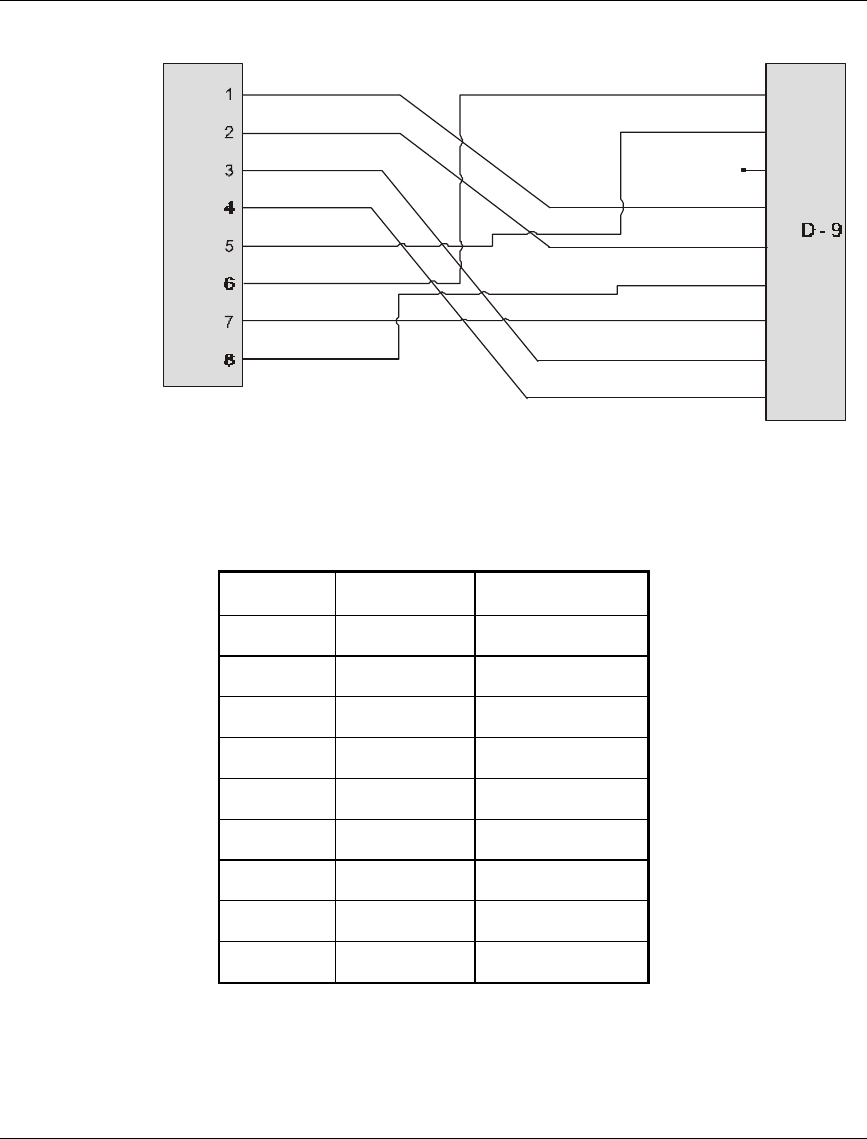
Figure 16. Bulgin to 9-Pin D-Type Pin Assignments
Table 1. Bulgin to 9-Pin D-Type Pin Assignments
D-9 BULGIN Description
1 6 ETH_TX-
2 5 ETH_TX+
3N.C.
4 1 DC_0V
5 2 DC_-48V
6 8 ETH_RX-
7 7 ETH_RX+
8 3 TEL_TIP
9 4 TEL_RING